

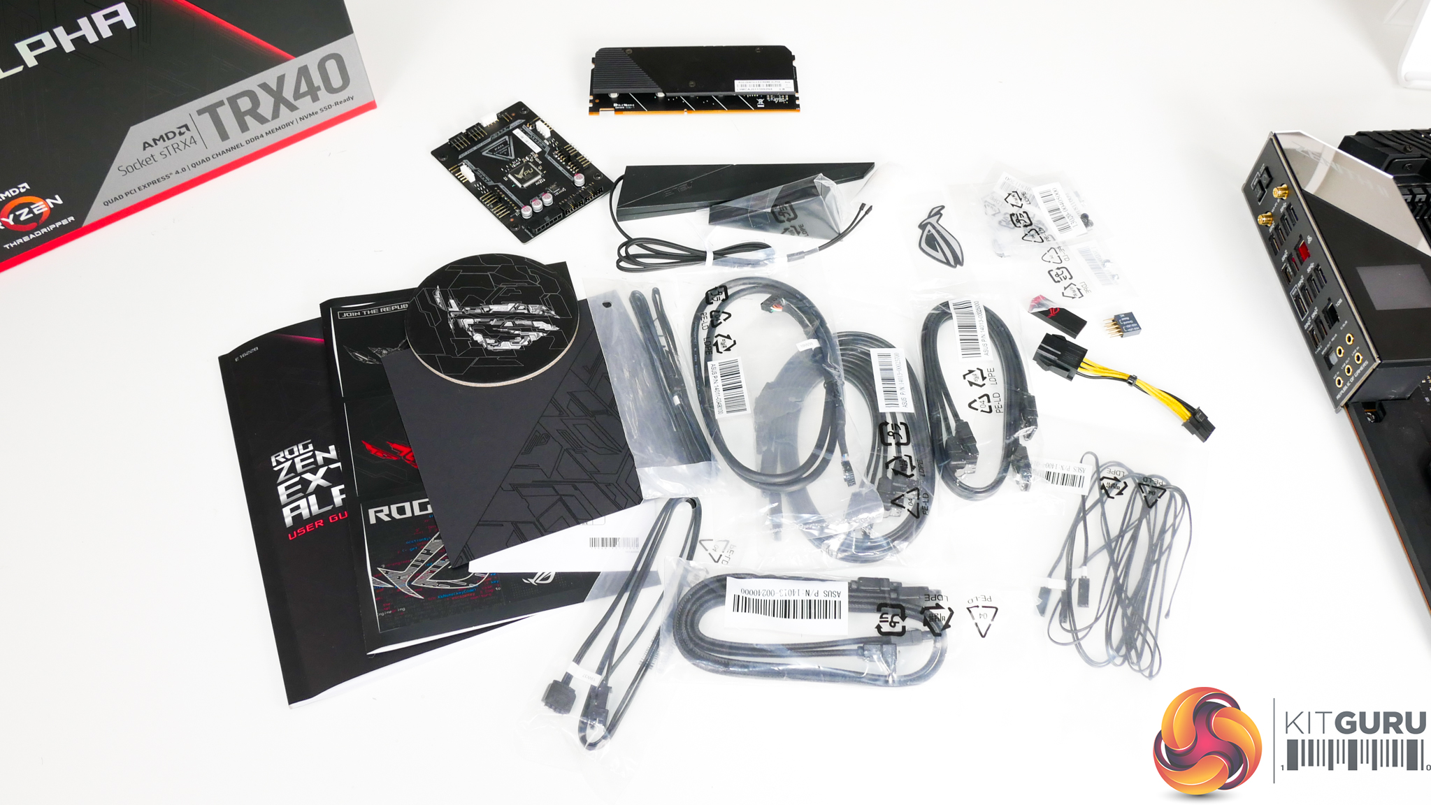
The bundle that ASUS supplies with its flagship TRX40 motherboard is extremely healthy. You get cables, screws, a USB drive, stickers, a coaster, and added-value cards.
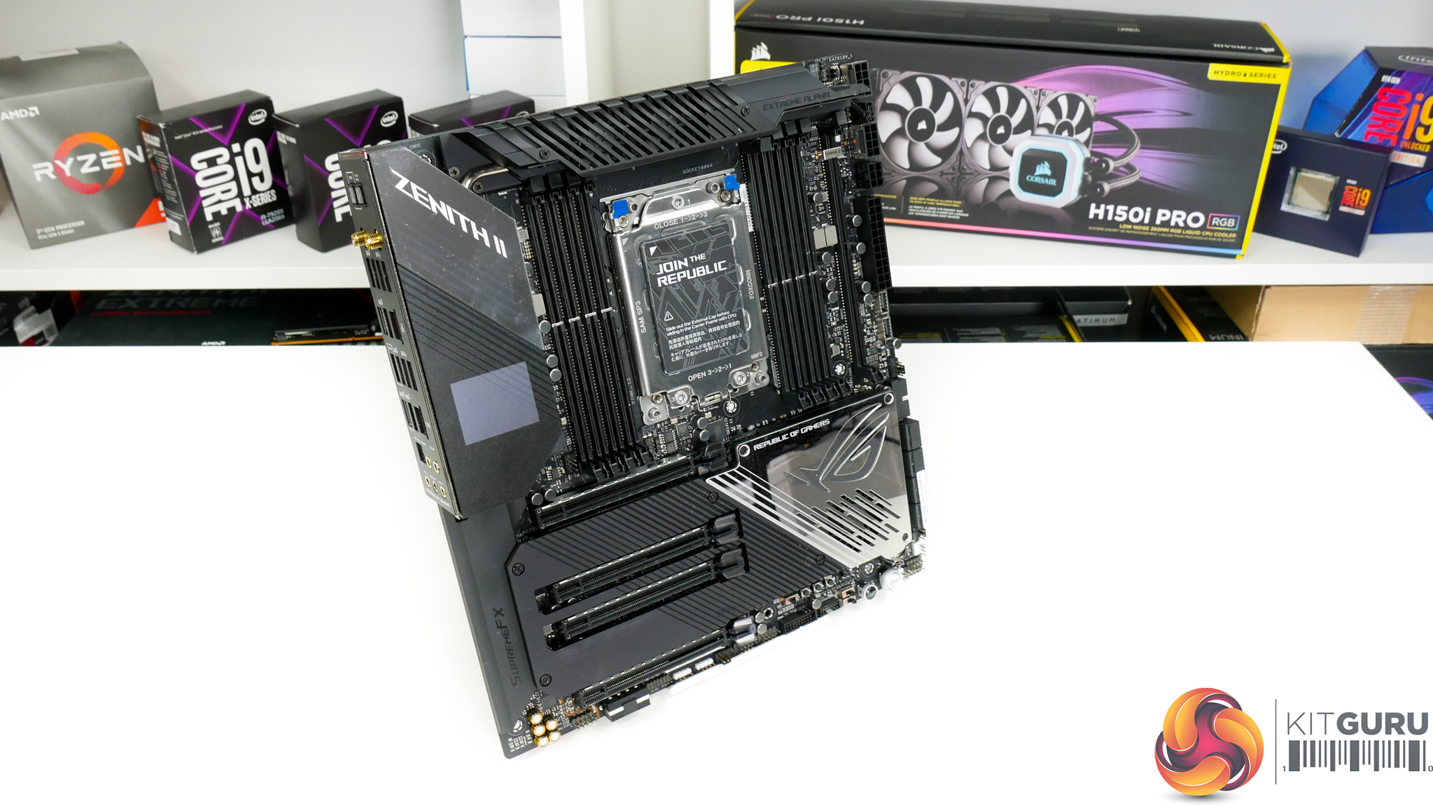
Style wise, we see the typical ROG colour scheme. That is, black and grey for the bulk of the motherboard, with zones of contrast provided by onboard and controllable RGB LED lighting.
In terms of physical size, the Zenith II Extreme Alpha is an Extended ATX motherboard. E-ATX is a challenge for many mid-tower cases but should fit fine in larger chassis. Either way, E-ATX is a far easier solution to manage from a chassis perspective than the XL-ATX form factor we see Gigabyte opt for.
A large shroud covers the bottom half of the motherboard, but it is relatively easy to remove with the board out on a table. The shroud is made from aluminium and features M.2 SSD cooling pads. Adding together all of the heatsink weight provides a motherboard that weighs more than 2kg and feels extremely sturdy.
You also get dual BIOS chips which is a somewhat unusual inclusion for ASUS. I like the redundancy and resiliency perspective of having the backup BIOS, especially for a motherboard of this expense.
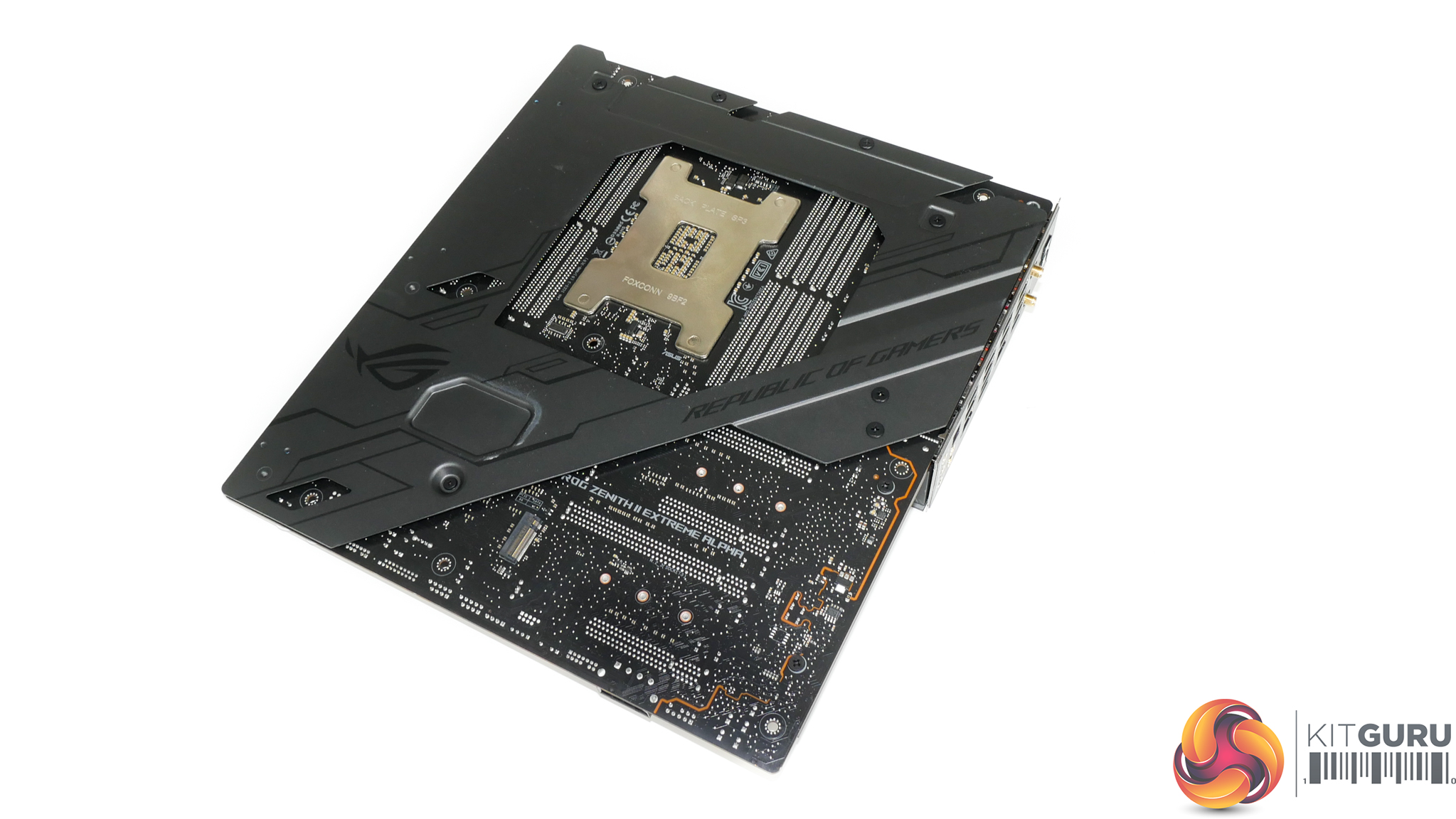
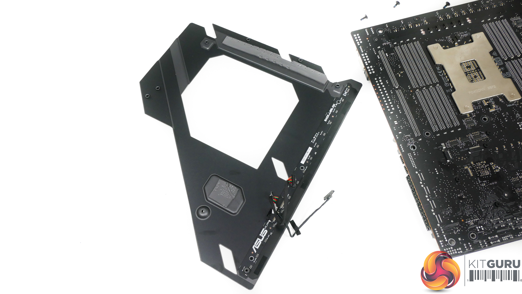
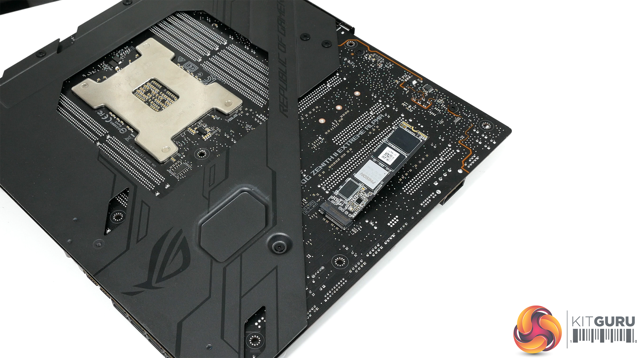
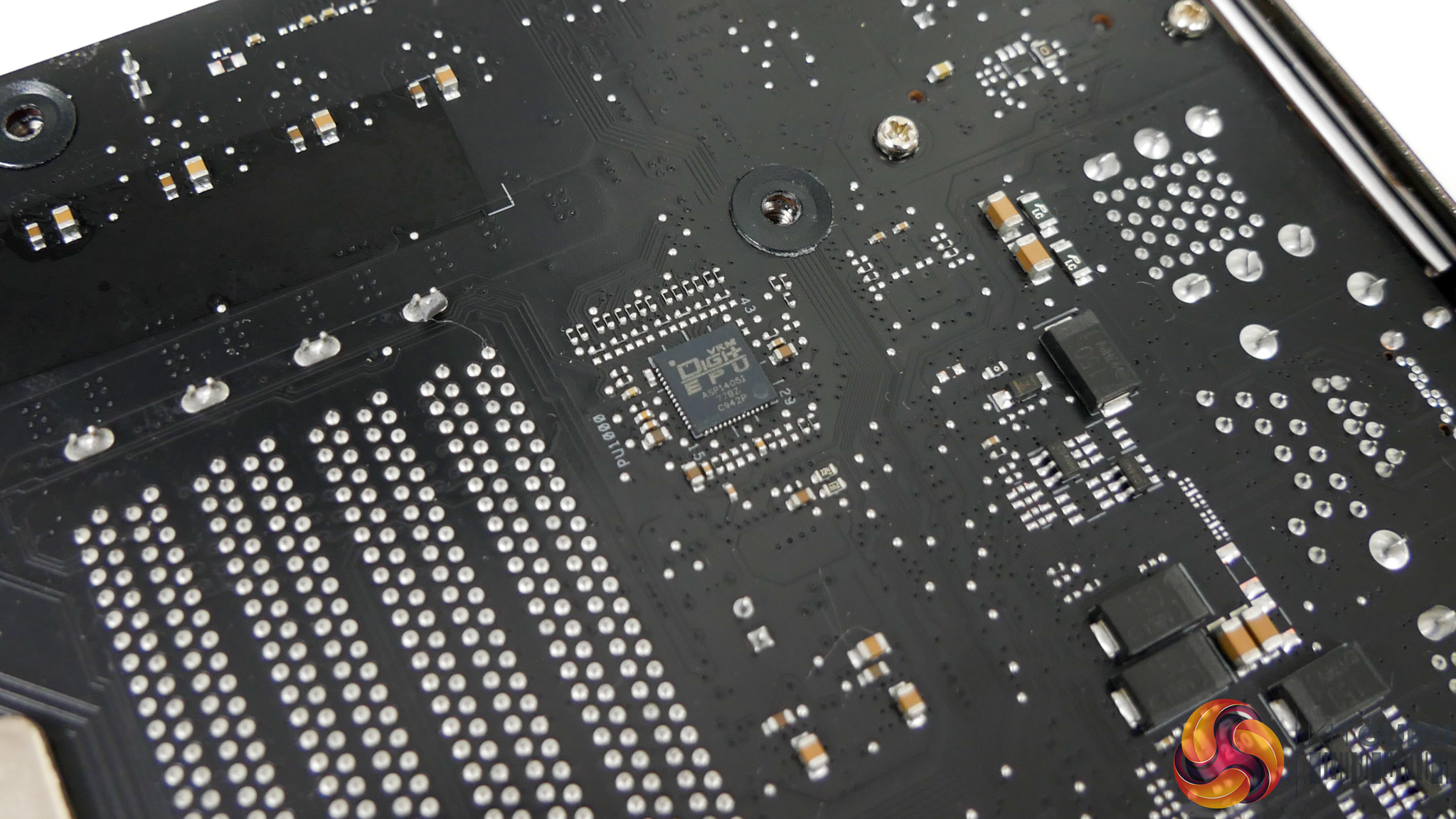
The cold-rolled steel backplate is primarily used for stiffness and rigidity enhancement. It manages both of those tasks very well, and that's important for such a heavy motherboard that could have further weight added via a large CPU cooler.
Direct contact via thermal pads is made with specific locations on the motherboard's PCB rear side. Of note is the large thermal pad mounted directly beneath where the VRM MOSFETs reside. Being steel, thermal conductivity is not going to be ideal from a cooling perspective and you certainly won't match the performance of Gigabyte's aluminium backplate. However, a decent sized lump of metal should do a reasonable job at whipping some heat away from the PCB.
The right-side RGB lighting strip is housed on the backplate and operates via a pair of connector cables.
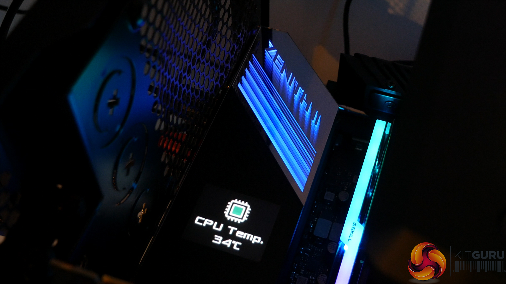
Functionally useful, rather than a simple gimmick, I like ASUS' inclusion of the 1.77″ LiveDash OLED display. You can display things like monitoring information, words, and different colours on the screen. This is important if you want to see how hot your CPU is running during system operation or whether your BIOS update is actually taking place.
The two-digit debug LED has been a long-term favourite of mine. But ASUS' OLED display is a far superior option and is found in a smart location. No doubt it adds noticeable costs to the motherboard, though.
RGB lighting is primarily provided in three main zones: rear IO cover, chipset, and right edge strip. I like the subtly of ASUS' implementation and you get good control capabilities thanks to AURA software. The ‘infinity-style' RGB cover found above the LiveDash OLED display is my particular favourite as I think it looks very appealing when the system is running.
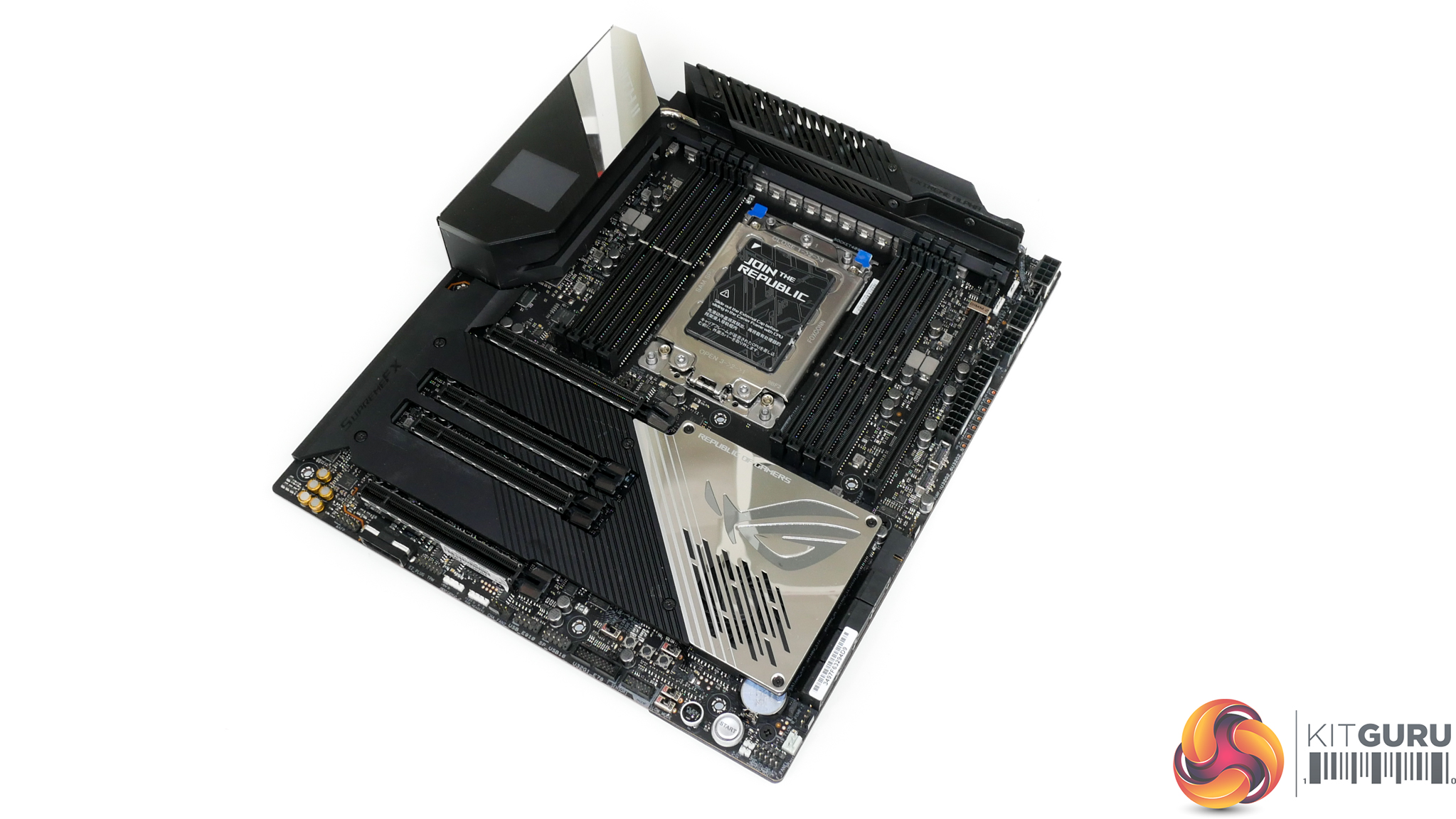
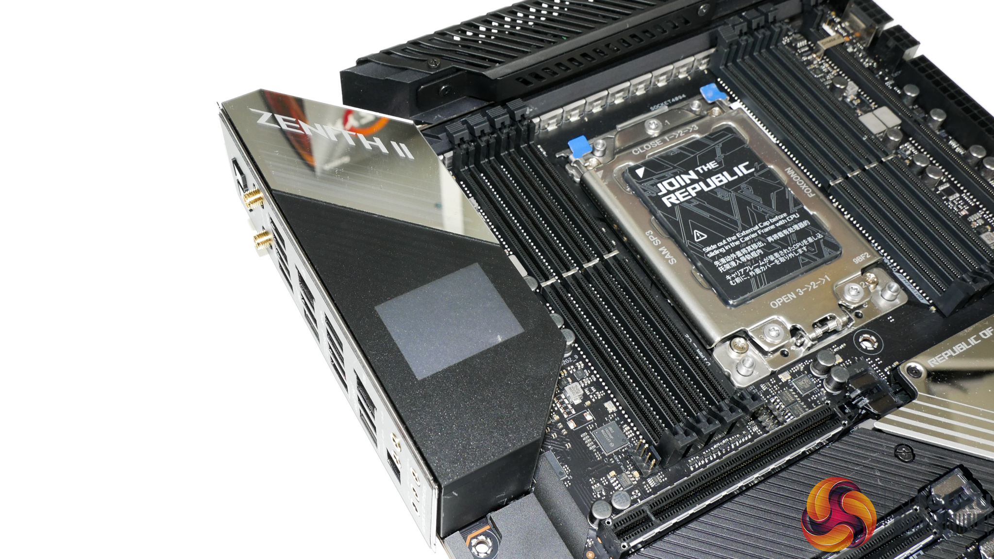
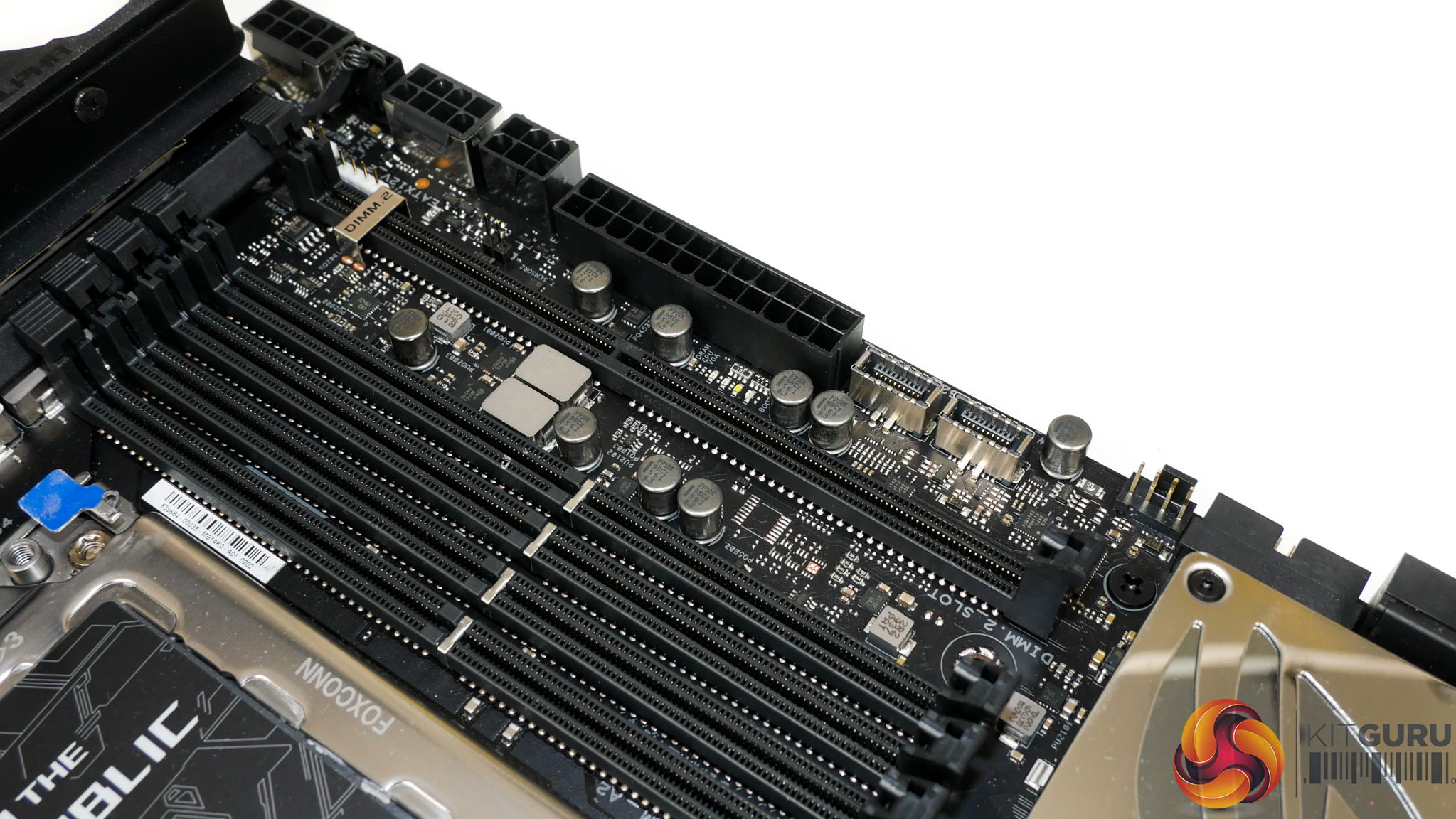
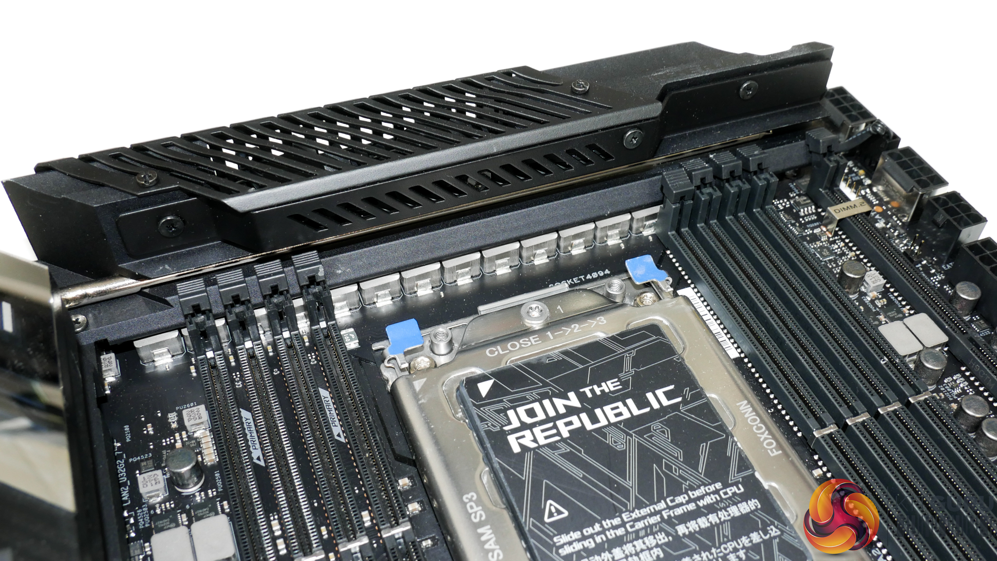
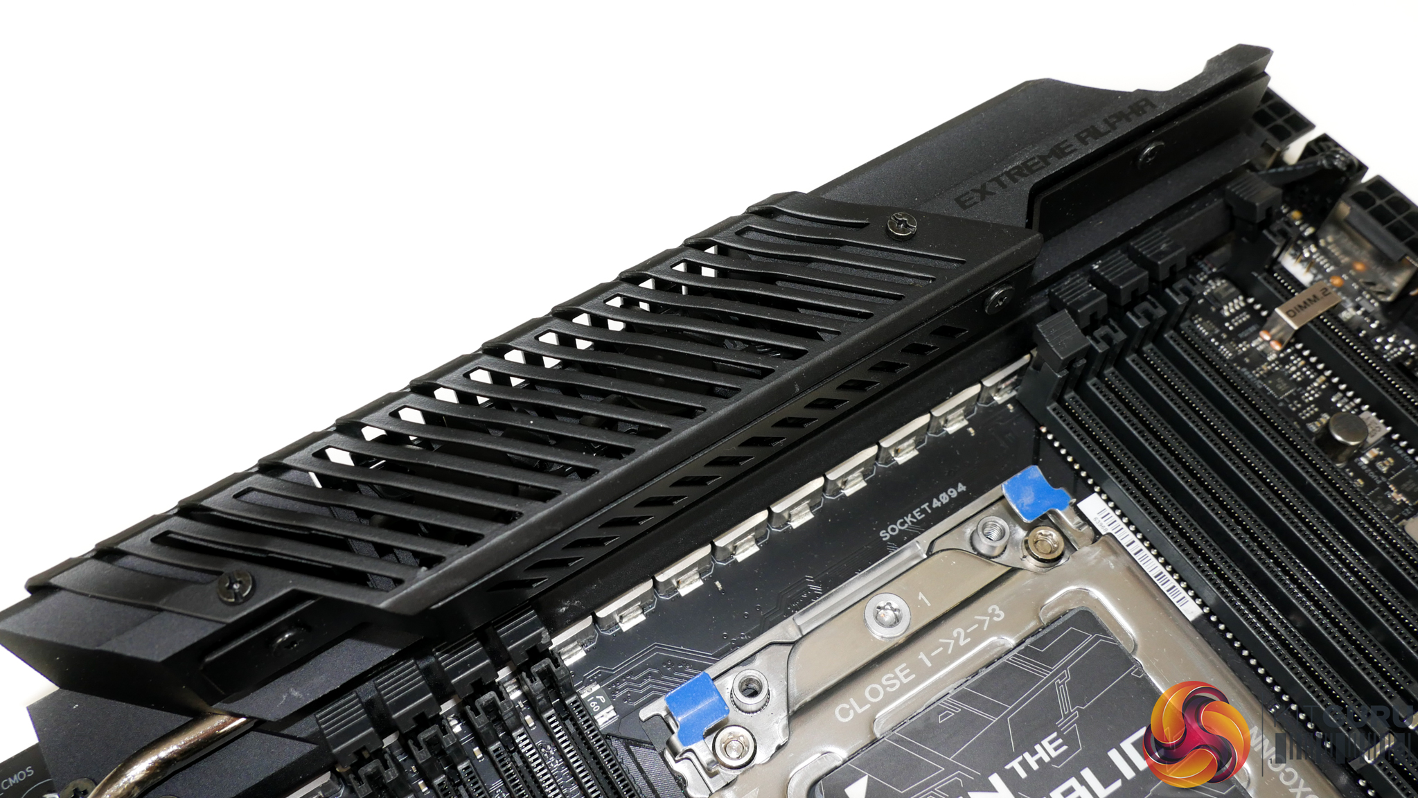
Sat either side of the massive sTRX4 CPU socket is a set of 4-DIMM banks. You get eight DIMM slots in total which allows installation of up to 256GB of DDR4 using standard non-ECC modules. The fastest kits highlighted on ASUS' QVL are DDR4-4600MHz offerings from Corsair and G.SKILL. ECC memory module support is also noted in the QVL.
Positioning of the large VRM heatsink, combined with ASUS' single-latch DIMM slots, makes accessing the removal notch very difficult. ASUS includes a specific screwdriver for the task of popping the module release latch, though this was not included with our sample.
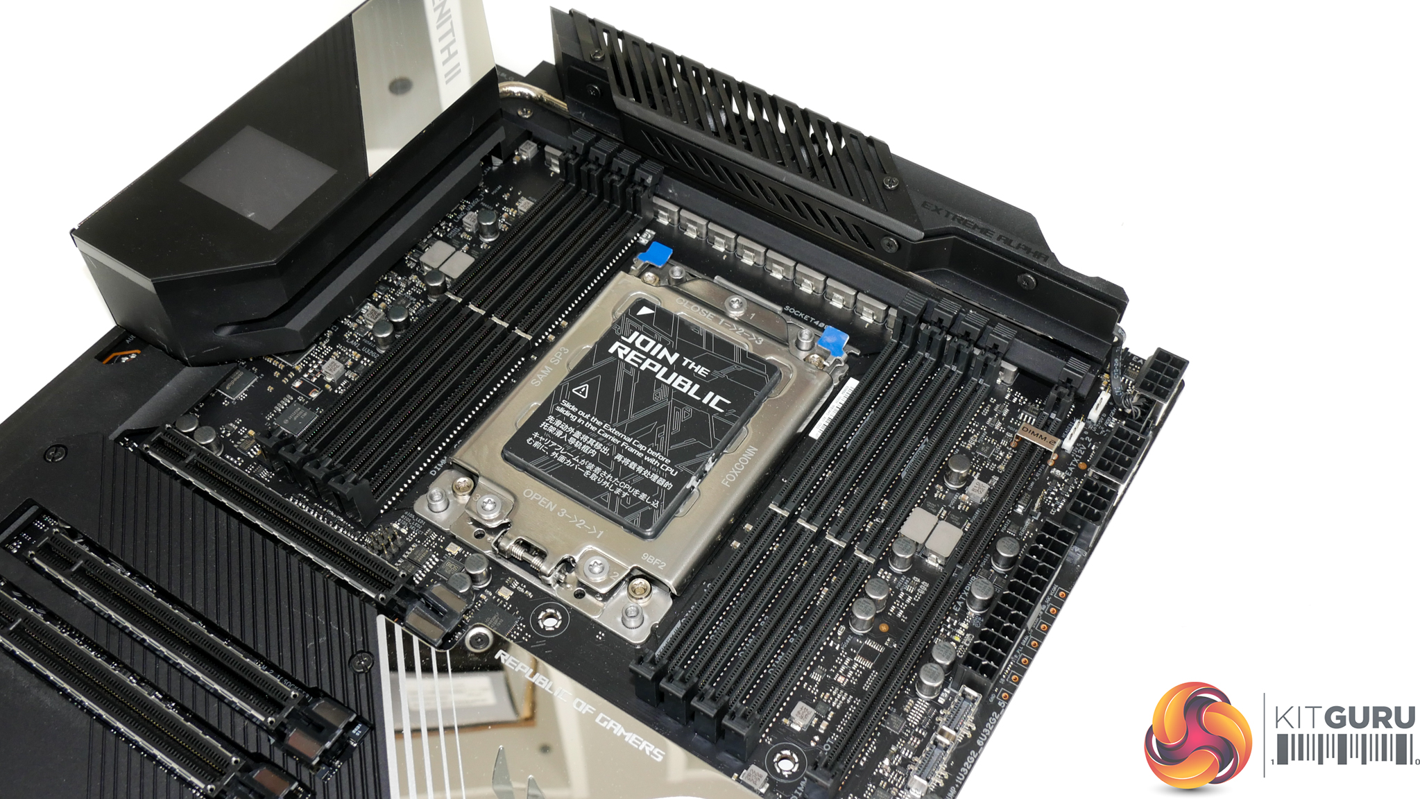
Vertical positioning of the CPU socket and DIMM slots is also likely to cause interference with CPU cooler and graphics card backplates. This is something that you have to watch out for. Thankfully, our Gigabyte Aorus RTX 2080 Ti Xtreme graphics card and Cooler Master Wraith Ripper CPU cooler worked fine together, even if it was a tight squeeze.
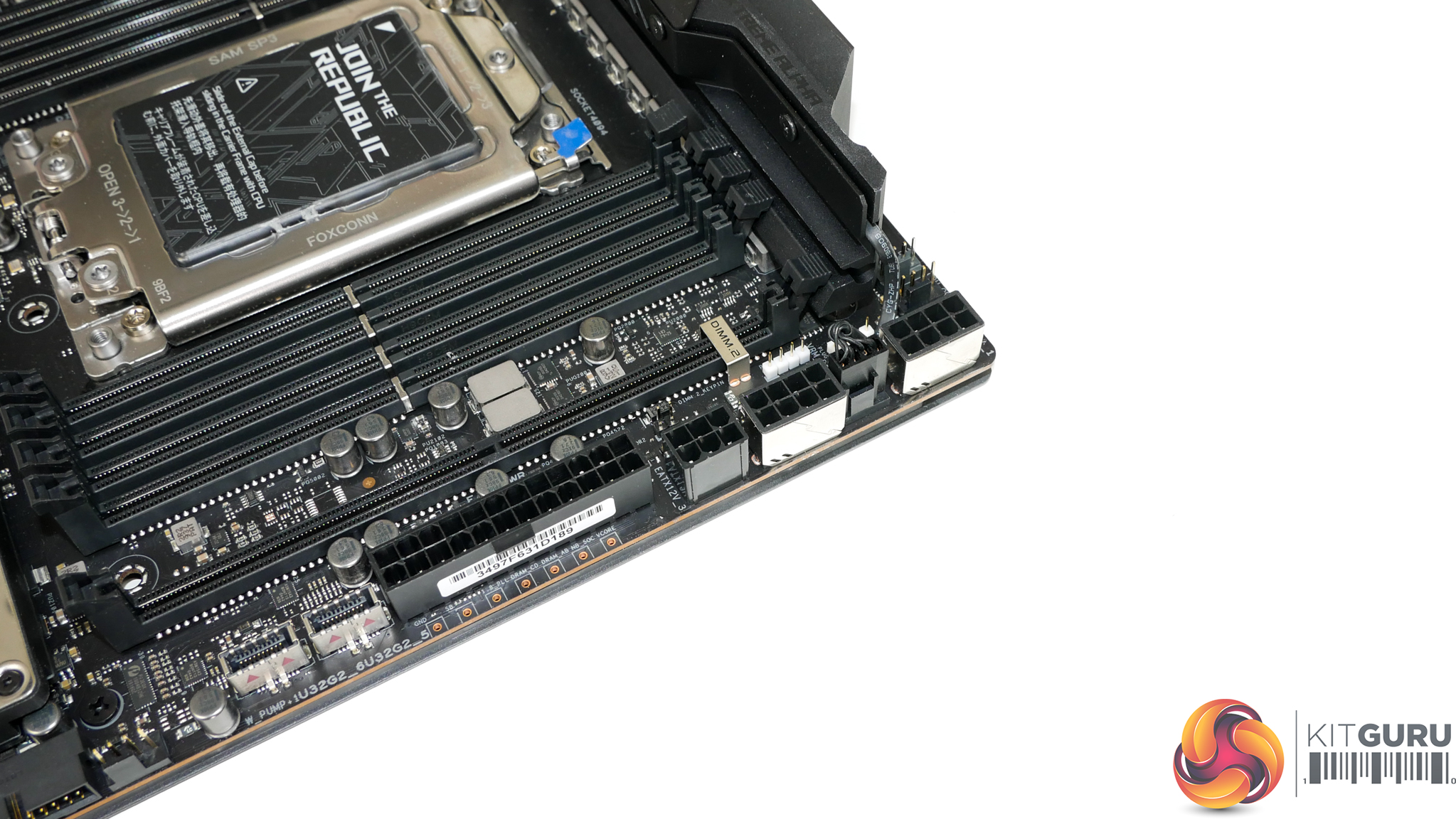
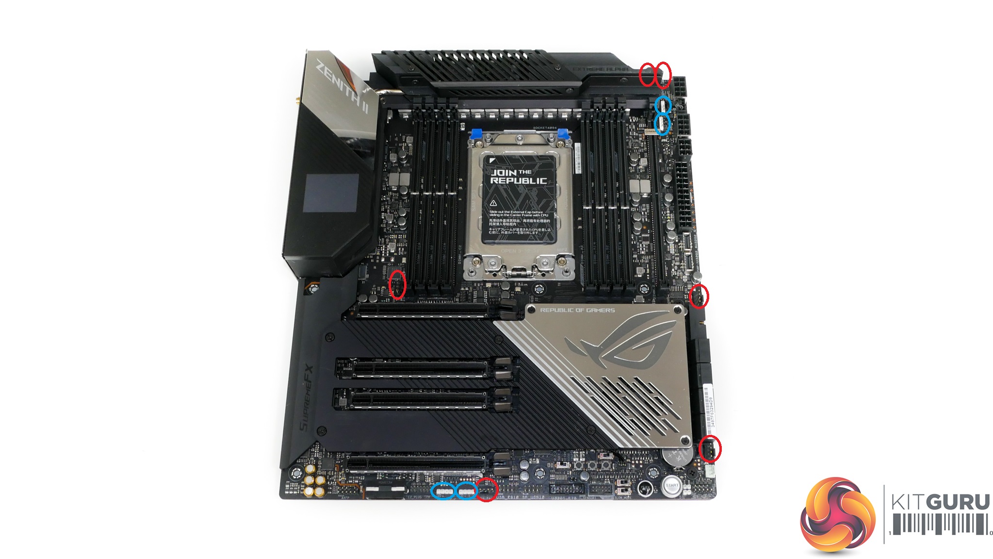
CPU-specific power comes from dual steel-reinforced 8-pin EPS connectors and a single 6-pin PCIe connection. Even enthusiast overclockers pushing a Threadripper CPU hard should not have to worry about power delivery concerns from this motherboard. Positioning of these connectors in the motherboard's top-right corner is a move driven by the VRM cooler hogging most of the PCB's top edge real estate.
ASUS' inclusion of onboard voltage monitoring points is a feature that I love to see and something that I consider a necessity for an elite level overclocking motherboard. You also get a thermal sensor header in the top-right location which allows you to plug in the thermistor cable and monitor nearby components such as memory modules or VRM heatsink surface temperature, for example.
Dual USB 3.2 Gen 2 10Gbps Type-C headers is good to see. Both of these headers run individually without sharing bandwidth, so you should be able to use both simultaneously with minimal transfer rate slowdowns.
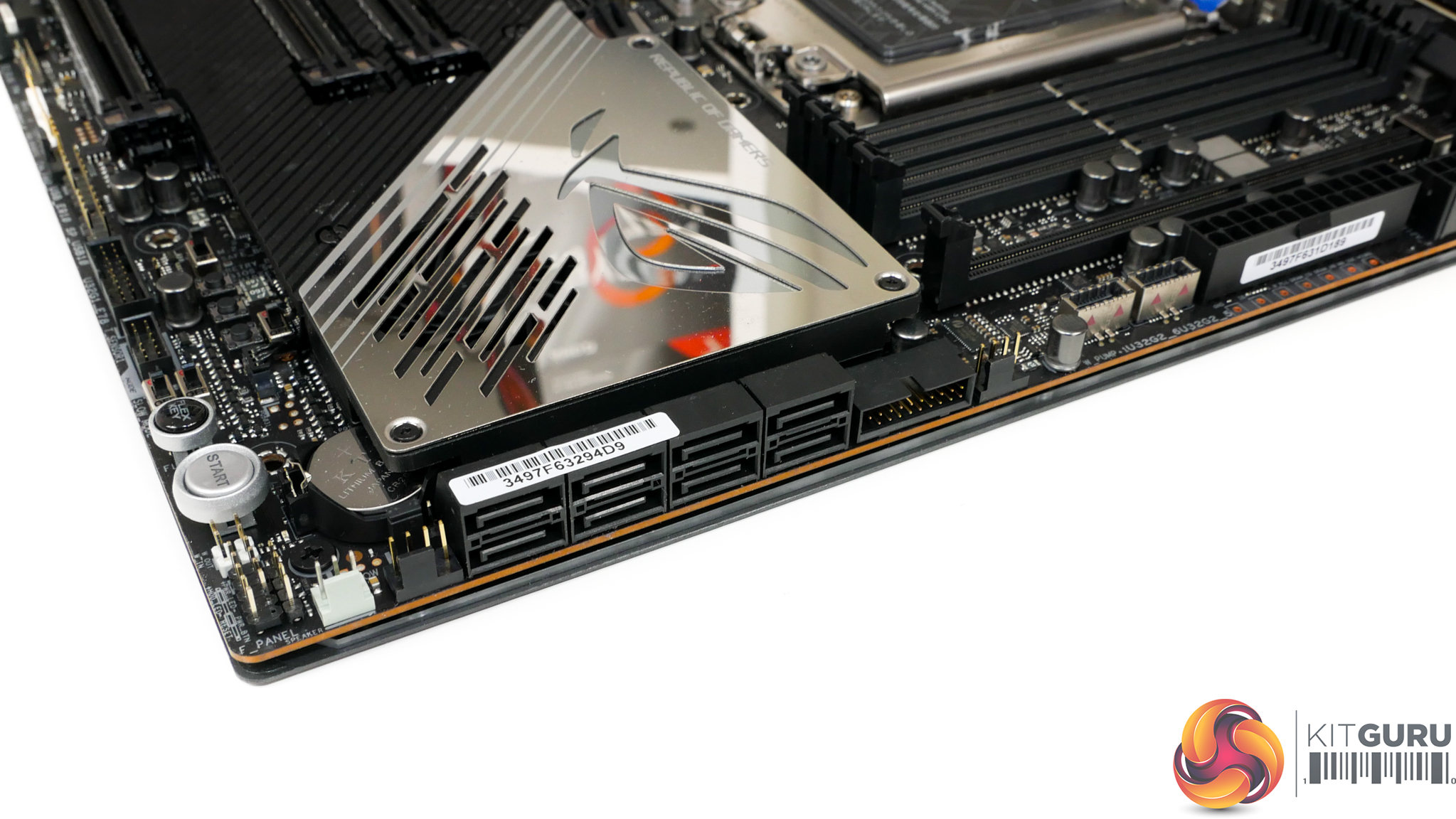
While there are clearly eight SATA 6Gbps ports in total, only four of these run from the TRX40 chipset. The other four are provided by a pair of ASMedia controllers and are therefore bandwidth limited to two PCIe Gen 4.0 lanes by comparison to the TRX40 options. Another caveat is that the four ASMedia-powered ports share bandwidth with the rear M.2 connector and therefore cannot be used whilst an SSD is installed in that location.
One of the board's two USB 3.0 5Gbps headers is located next to the SATA ports. The right-angled orientation is ideal for cable management though you certainly need a wide case to be able to make such a cable run with this E-ATX motherboard. Bandwidth for the ports is shared with the other header's two ports via a single 5Gbps USB 3.0 link to the TRX40 chipset.
As such, you need to be careful of significant slowdowns when transferring files from more than one storage device that is connected to these front panel ports. If in doubt, split drive connections between your front panel ports and the rear IO ports as they run with different bandwidth links.
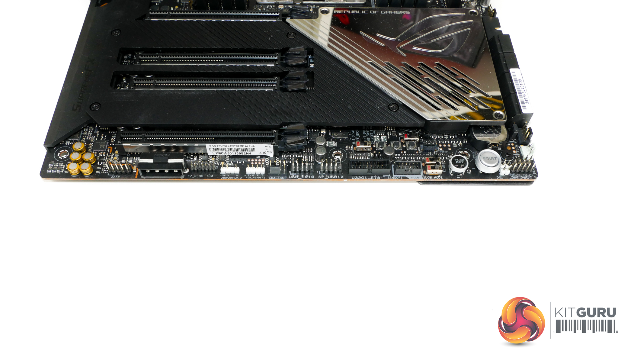
You get the usual set of connectors along the motherboard bottom edge. ASUS also adds a 4-pin downwards facing Molex for supplementary power, in addition to the ASUS NODE connector for the fan extension board.
Switches controlling the system operating mode when pushing hard overclocks are positive additions. This is good as you don’t have to crash and rely on the dual BIOS chips for resiliency. The onboard buttons are in a good location, especially as the alternative area near the DIMM slots is highly likely to be covered by extreme cooling for enthusiast overclockers.
Two USB 2.0 headers are provided, but one of them only supports a single port, which is a bit bizarre but is fine for AIO coolers and the likes. The other header uses a single USB 2.0 chipset link and a hub to split into two connections.
Liquid cooling connectors for things like water flow sensing are found in the bottom right section. One notable omission that may disappoint some potential buyers is the lack of a Thunderbolt 3 AIC internal header.
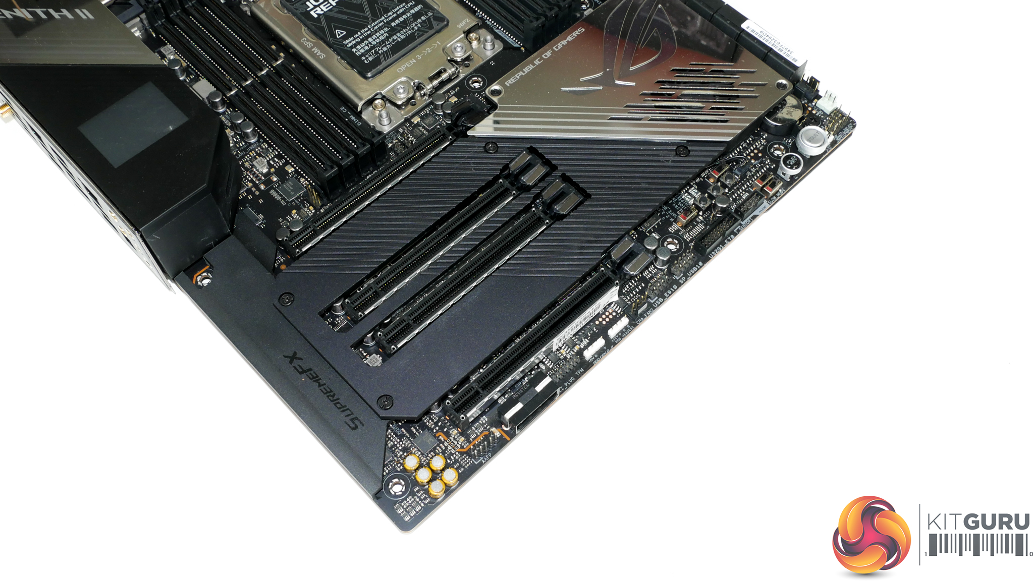
Four full-length PCIe slots are provided with varied bandwidth allocations. From top to bottom, the slots run at x16, x8, x16, x8 with Gen 4 lanes coming from the sTRX4 CPU. I would argue that this slot layout is about as good as one can expect for a motherboard of this calibre without going for the unfavourable XL-ATX form factor.
You can do 3 cards with dual-slot coolers, although at least one will have to run at x8 bandwidth and you need an 8-slot case. With two dual-slot graphics cards, you can do x16/x16 and still have x8/x8 slots available for expansion devices such as the ASUS Hyper M.2 Gen 4 card. You can also do dual triple-slot cards, but this uses or blocks all the expansion slots.
M.2 slot 2 (the one directly above the bottom PCIe slot) shares bandwidth with the bottom PCIe slot. With an M.2 SSD installed, the PCIe slot will be limited to x4 bandwidth. As such, that would limit users to only dual graphics cards capability at reasonable bandwidth (given the slot layout), so watch out for that.

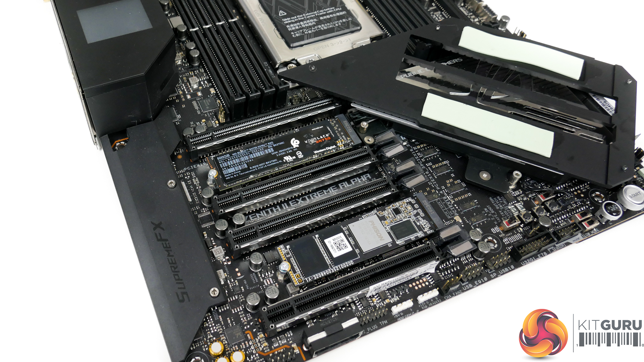
A total of five M.2 connections are available, which is highly impressive and somewhat negates the requirement of an M.2 add-in-card adapter like we see from competing solutions (that steals a valuable expansion slot). Not all of these M.2 slots can be used with SATA SSDs and some also steal bandwidth from other devices, so it is important to pick your installation wisely.
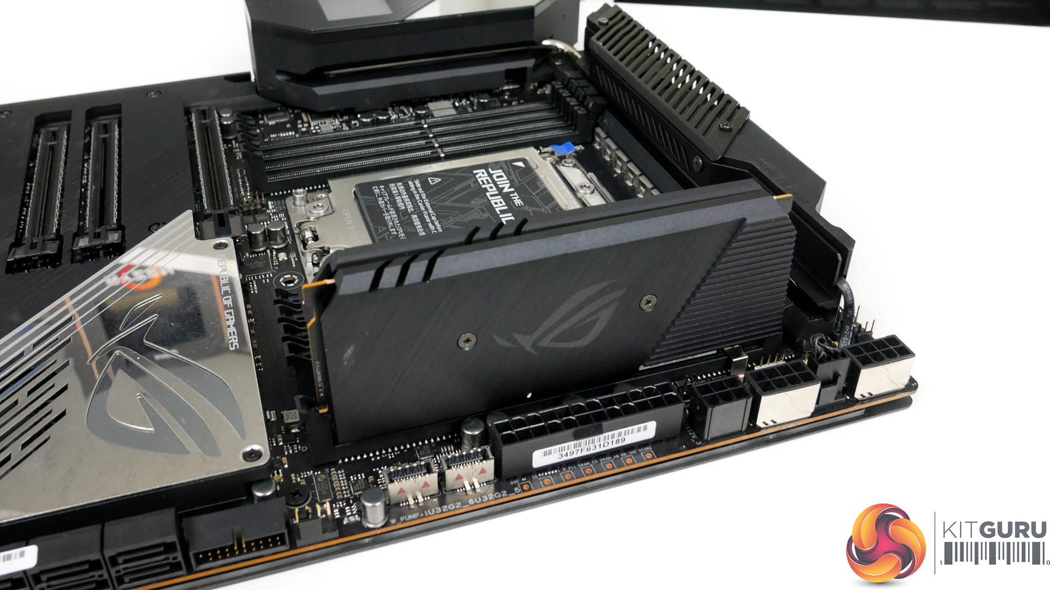
M.2 slot 1 and slot 2 sit beneath the motherboard’s expansion slot area heatsink. They are cooled by thermal pads attached to the sizeable metal plate. Installation with expansion devices already installed will be time consuming as you have to remove the cooling plate.
M.2 slot 1 (upper) and 2 (lower) run at up to PCIe Gen 4 x4 bandwidth from the Threadripper CPU lanes and DO NOT support SATA. Slot 2 shares bandwidth with the lowest PCIe expansion slot, which needs bearing in mind when deciding the best installation approach. Both slots support up to 80mm SSDs.
M.2 slot 3 (rear) sits on the back of the board and runs at up to PCIe Gen 4 x4 from the TRX40 chipset. It steals bandwidth from the 4 ASMedia-powered SATA ports and will render them unusable with a PCIe x4 SSD installed. The rear slot also has limited cooling capability as it does not have a heatsink attachment or good access to airflow, given its rear mounting. An SSD up to 80mm in length can be installed.
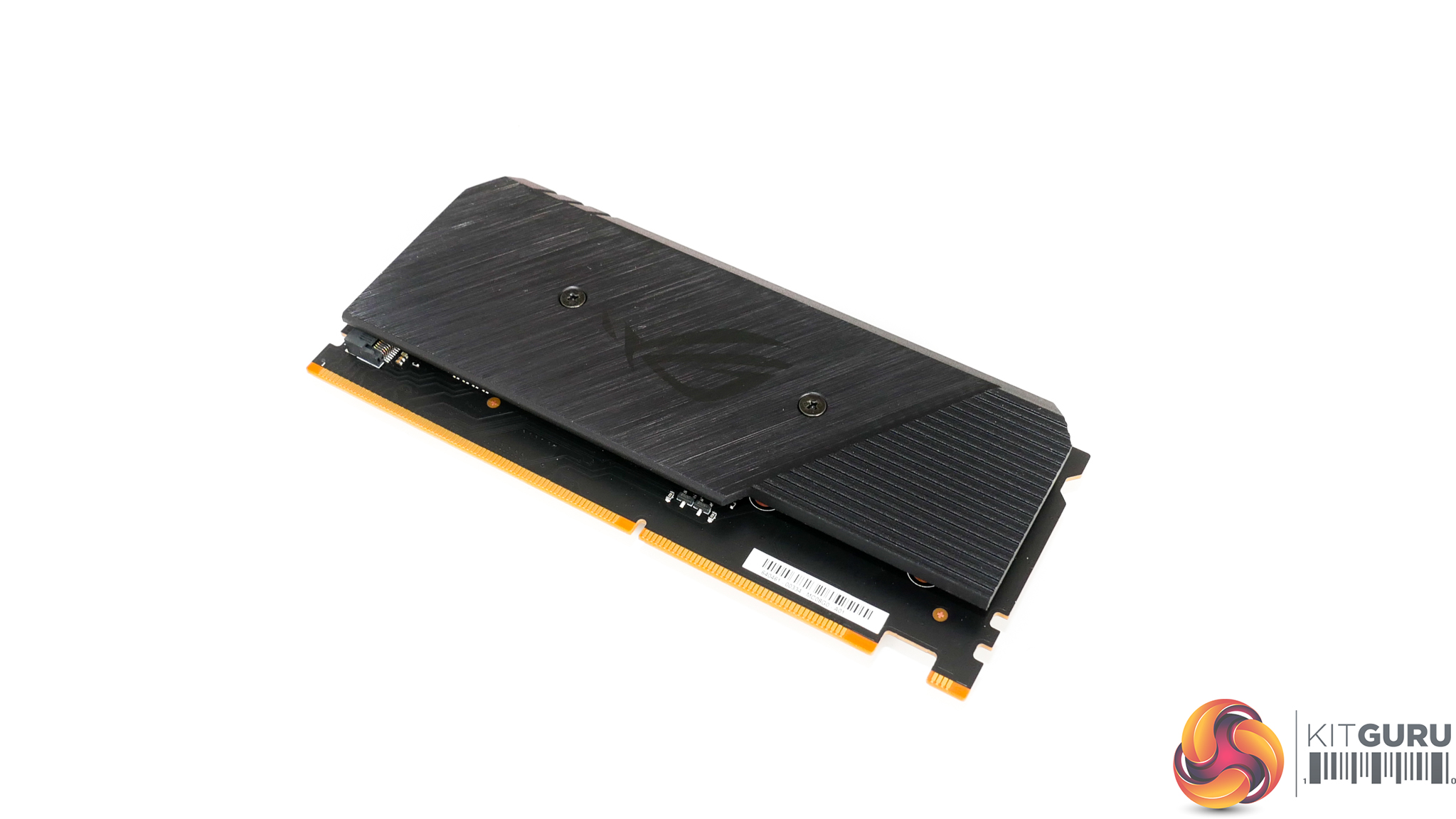
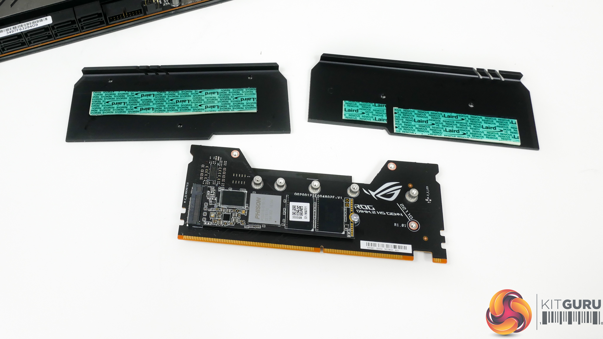
Slots 1 and 2 on the very useful DIMM.2 card support PCIe Gen 4 x4 and SATA 6Gbps connections and are fed by the TRX40 chipset. These connections do not share bandwidth with anything else on the motherboard and can therefore be used without affecting anything else.
I am particularly fond of ASUS' DIMM.2 card as it features a good cooling system thanks to its metal housing and thermal pads. This cooling potential is aided by the install position to the right of the DIMM slots which gives the add-in-card a good amount of airflow in a typical chassis configuration.
The card itself, as well as the SSDs it houses, are easy to install even after a full system build as the slot area is easily accessible and the card is easily removable. SSDs up to 110mm in length can be installed.
With a total of five M.2 connections provided, it takes some decisions as to which slots you should use in your system (unless you fill them all, of course). My personal usage would be as follows.
- Slot 1:
- Install a PCIe SSD in slot 1 first as it is easy to install when first building the system as it does not require expansion card removal as would be the case if the system was already built.
- It has good cooling and does not steal any bandwidth and it is direct CPU-fed lanes.
- Slot 2:
- Use slot 2 next for a PCIe SSD, ONLY if you are happy to run with reduced bandwidth on the bottom PCIe slot.
- It is easiest to be installed during initial system build as you need to remove expansion cards and the M.2 heatsink if your system is already built.
- It has good cooling and does not steal any bandwidth and it is direct CPU-fed lanes.
- Slot 3 (rear):
- Use slot 3 as a backup-type slot or if you have a slower M.2 SSD and will NEVER use the four ASMedia-powered SATA ports.
- It does not have active cooling so is not good for a fast SSD with sustained write operations.
- It is difficult to access the back of the board, so is not good for upgrading with a new SSD in the future when the system has been fully built.
- The slot is fed through the TRX40 chipset, so there is potential for bandwidth limitations when reaching to the CPU for data.
- I personally think that an OS SSD would be OK in this slot as it will not be pummelled with heavy, sustained write operations and you won’t physically access it regularly.
That leaves the DIMM.2 card spare. If you can deal with the bandwidth, cooling, and installation limitations of the board-mounted slots, I would be inclined to leave the DIMM.2 slots free as the install process is very simple for upgrades when a system is fully built. It is incredibly easy to install SSDs in this card and simply pop it into your system without dismantling or removing other components.
I would also use these slots if you need to install more than three SSDs (obviously) or if you do not want to deal with bandwidth sharing limitations that you get from some of the board-mounted connections. There are, however, potential bandwidth limitations if both of the chipset fed SSDs were reaching out to the CPU for data simultaneously, along with other system devices.
Given the beneficial cooling potential of the DIMM.2 card, it is also worth using these connections if you have a hot-running SSD that is regularly hit with heavy, sustained write operations.
Credit to ASUS for giving ample M.2 flexibility without forcing users to sacrifice a physical expansion slot by using an adapter card for multiple SSDs.
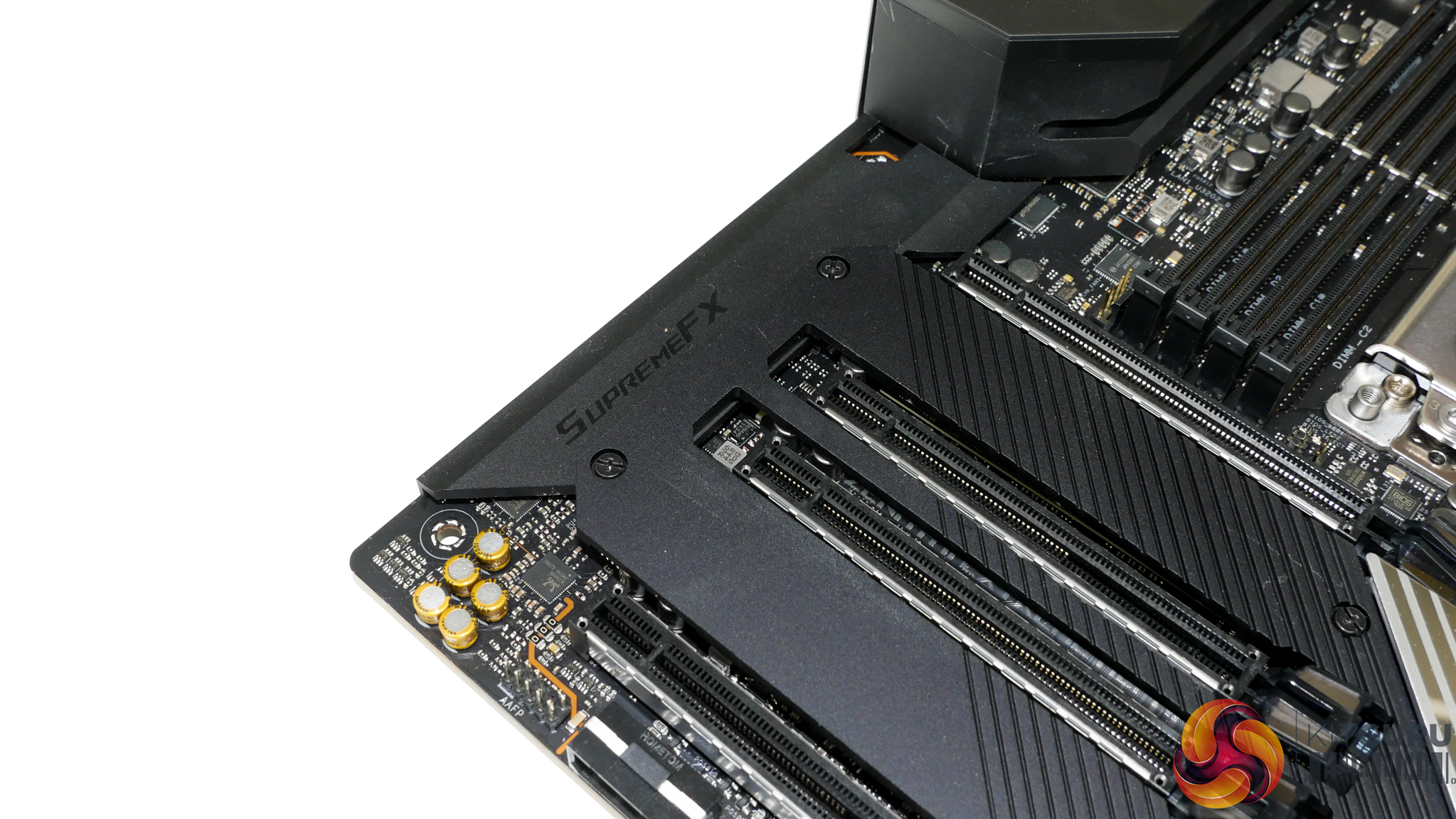
ASUS' SupremeFX audio system is based around the SupremeFX S1220 audio codec and uses the Realtek ALC4050H chipset to convert from the USB 2.0 connection on the chipset. You also get an ESS Sabre 9018Q2C DAC, Nichicon audio capacitors, and dedicated audio tracks.
A cool little feature is the LED illuminated audio jacks on the rear IO.
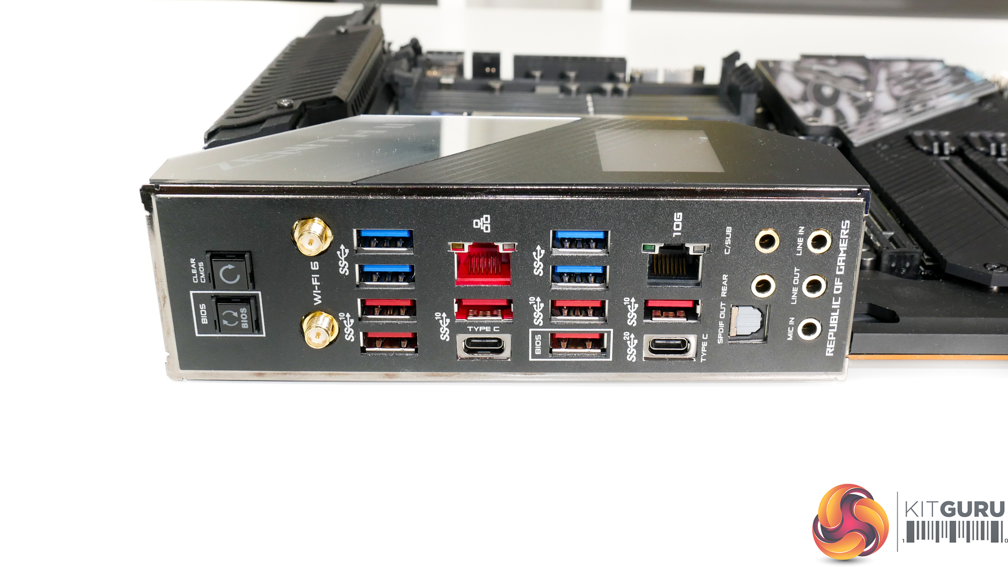
I would go as far as saying that the rear IO is pretty much perfect for a flagship, enthusiast motherboard. Obviously, you get the integrated IO shield and also the IO cover on the front of the board which houses the LiveDash OLED display.
You get ten USB Type-A ports, six of which are 10Gbps, with one of those being allocated BIOS Flashback duties. The 10Gbps run at full speed with four from the CPU and two from the chipset. No hubs or controllers are used. The 5Gbps ports, however, all run from a single 5Gbps link to the TRX40 chipset that is then split out to 4 ports via a hub chipset. This will introduce bandwidth penalties if hitting the ports simultaneously.
You get two Type-C ports, one of which runs at 10Gbps bandwidth from the TRX40 chipset, with the other operating at 20Gbps speeds via a dedicated USB 3.2 Gen 2×2 host controller.
10Gb Ethernet is provided by an Aquantia AQC107 NIC and you get the robust Intel I211AT as an addition. One could argue that the secondary NIC should be faster. I think 10G plus 1G is generally OK, though Gigabyte does opt for dual 10G via an Intel chipset. WiFi is provided by the Intel AX200 chipset and supports BT5.0 as well as WiFi6 with up to 2.4Gbps bandwidth.
Rear IO buttons for BIOS Flashback and Clear CMOS are good to see. They’re positioned far enough away from USB ports to not be pushed accidentally. You get the usual set of audio connections.
Directly on the motherboard, ASUS provides four conventional 4-pin fan headers, two of which are dedicated to CPU fan duties. You also get an additional two 4-pin headers on the right and these are referred to as W_PUMP headers thanks to their higher current output capability. They can be used as conventional fan headers, if you desire.
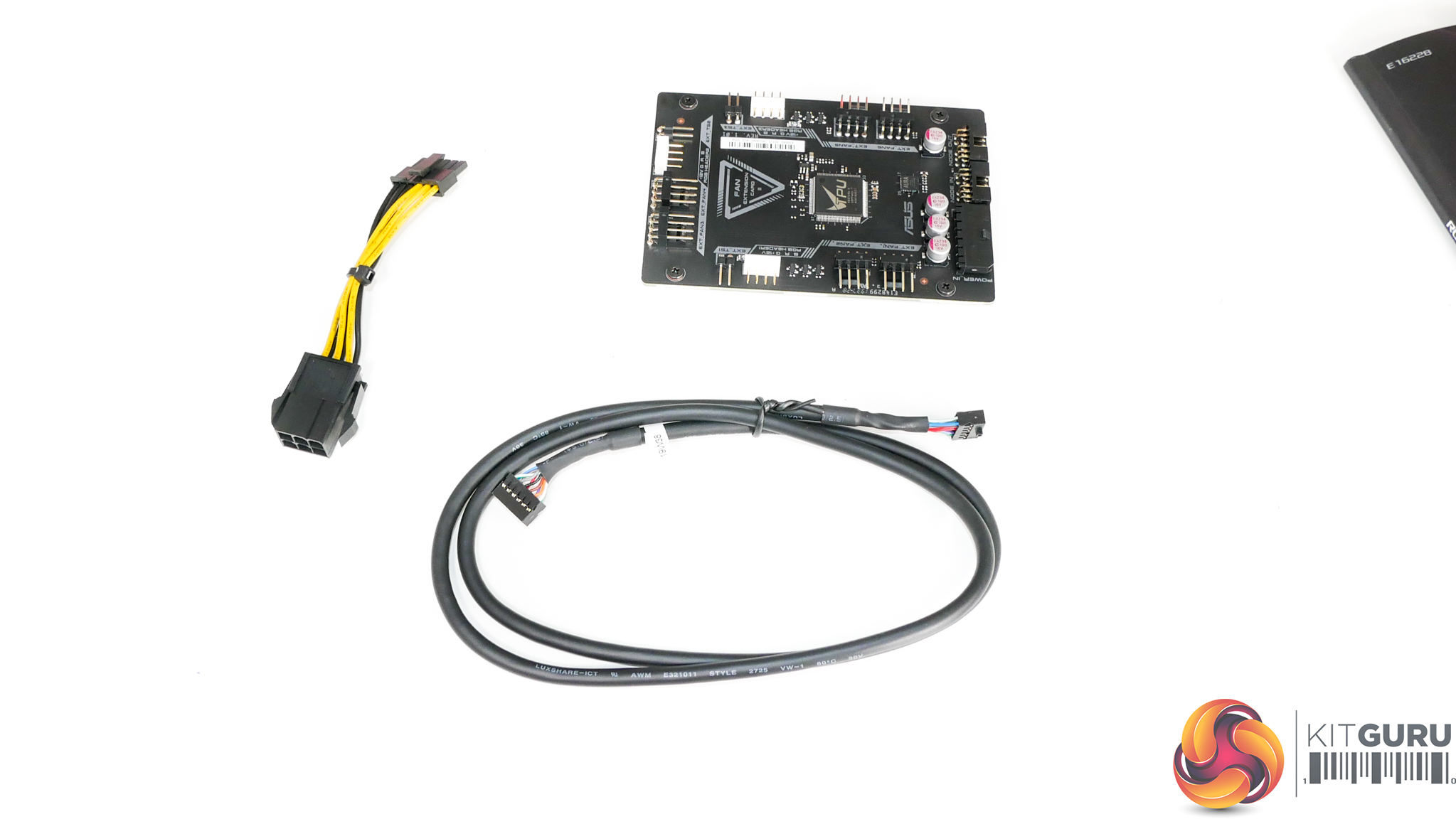
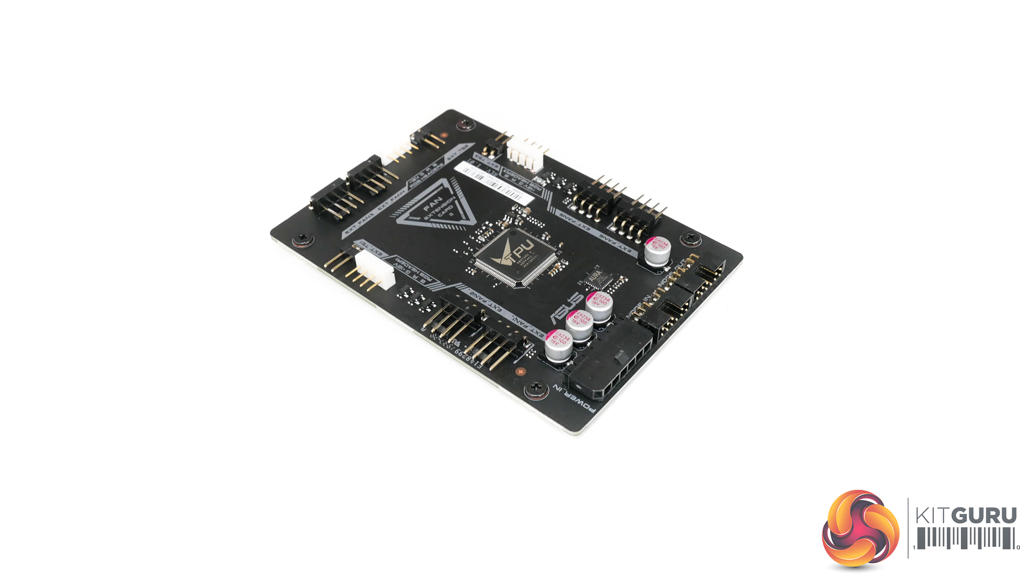
The fan extension card has an additional six 4-pin fan headers, and this makes a total of twelve headers, which is plenty even for a motherboard of this calibre. Also offered on the fan extension card are three more 2-pin thermal sensor headers in addition to the one header onboard (and the further three temperature sensor sources built into the board).
In terms of RGB, you get another three 12V RGB headers on the break-out card to add to the two 12V RGB and two 5V addressable RGB headers onboard.
Board plus add-in-card distribution of the headers is excellent as you can place the fan extension card out of the way and run all cables to it, hidden and out of sight. The card has screws that line up with a 2.5” SSD mount which is very smart from ASUS and makes installation straightforward.
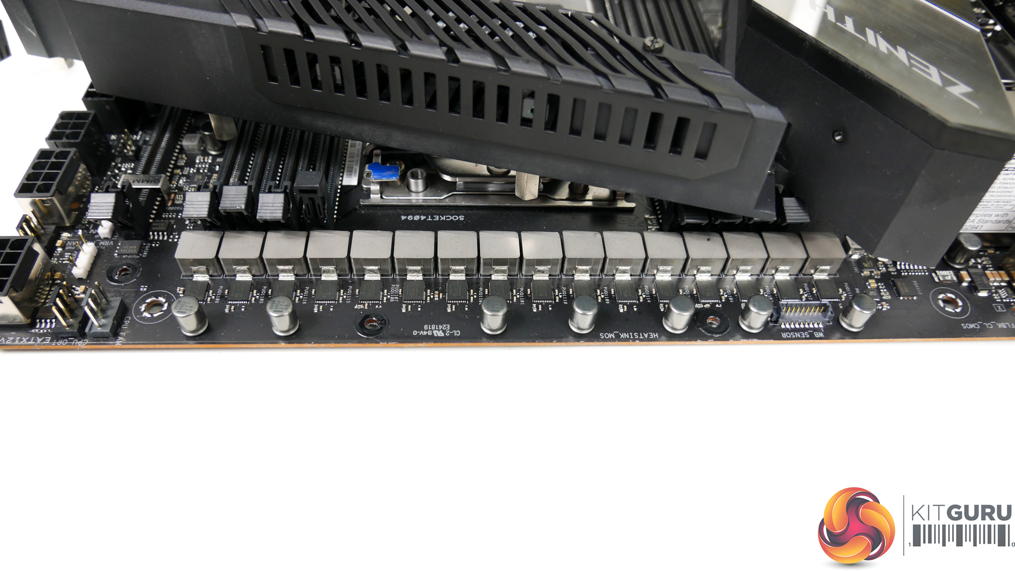
The sixteen-stage power delivery solution is built around the Digi+ ASP1405I PWM controller, which is essentially a rebadged Internal Rectifiers IR35201 which is a well-respected 8-phase solution.
You ‘only’ get eight control phases and ASUS does not use PWM phase doublers, so instead ASUS’ power stage teaming approach is used. Two of the power stages are controlled in parallel by one control signal. This eliminates the latency penalty of adding phase doublers while still giving the full current capacity of a 16-stage solution. The drawback is that you can get limited granularity compared to what more physical control phases would give you.
Gigabyte’s competing solutions, by comparison, use the Infineon 16-phase PWM controller even on the lower-end offerings. This true 16-phase controller used by Gigabyte is, on the face of it, a preferential solution compared to ASUS’ 8 control phases teamed power stage design.
The power delivery solution upgrade is the key difference between the Zenith II Extreme and the newer Alpha model. The former uses 70A power stages and the latter gets 90A treatment.
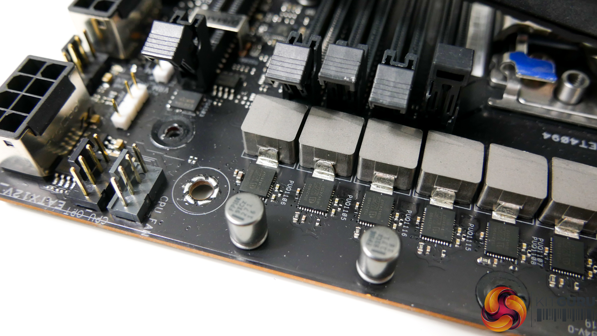
The sixteen power stages that feed a Threadripper processor are Infineon TDA21490 90A units. These are basically the best options on the market or are at least tied with the alternative 90A solutions that we have seen ASRock deploy. ASUS also deploys 10K-rated Japanese capacitors and 45A-rated chokes.
Put simply, the ASUS ROG Zenith II Extreme Alpha and its 16x90A power delivery solution is just about the best on the market for extreme overclockers pushing the current hard.
Gigabyte’s alternative approach with a true 16-phase controller is also extremely strong, but the TRX40 Aorus Xtreme’s 70A power stages cannot match ASUS’ board in terms of raw current capability. ASRock has a sixteen-stage option with 90A units, but these are based around the Intersil design spec and components as opposed to the generally preferred Infineon/International Rectifiers option for ASUS’ board.
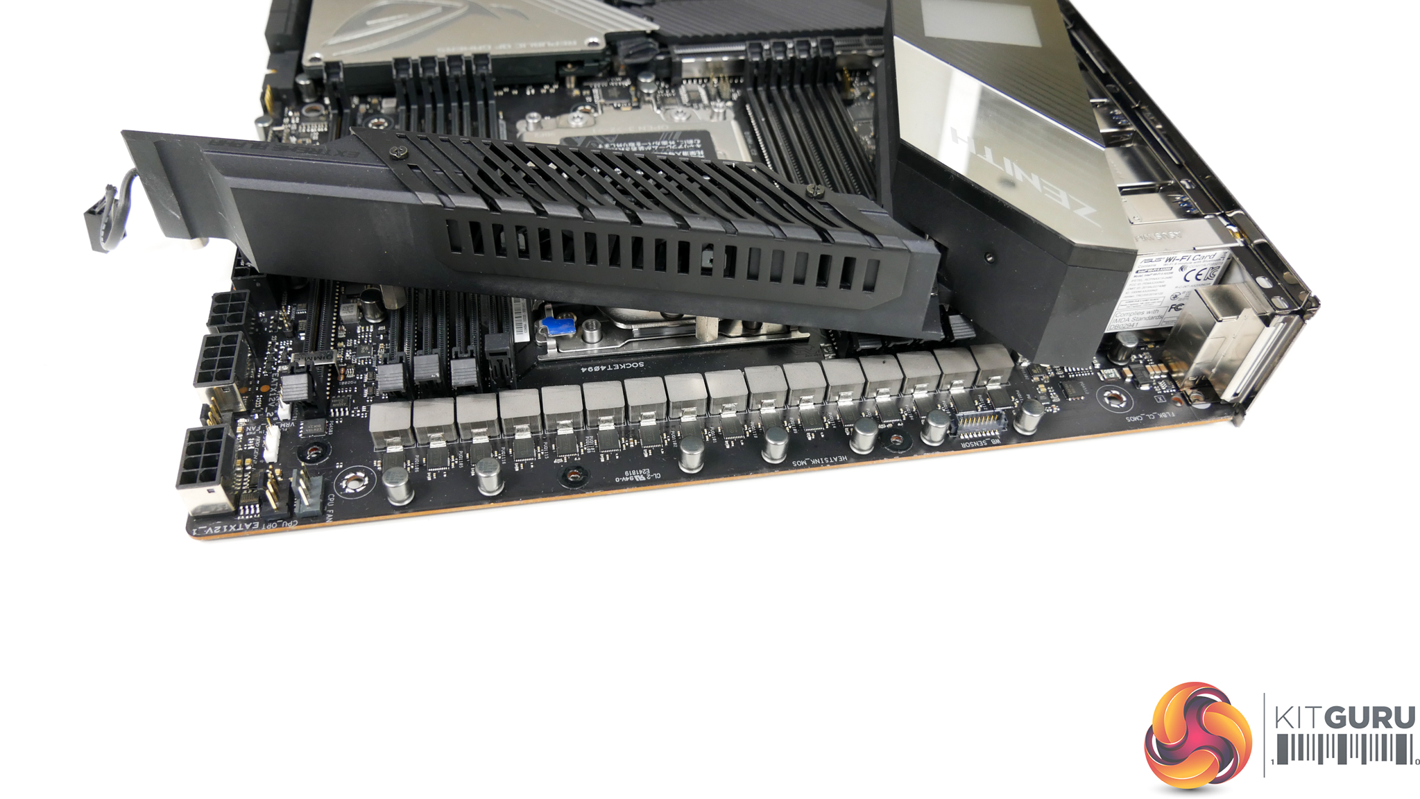
VRM cooling is handled by a sizable block of aluminium that connects via heatpipe to a secondary large slab of aluminium. I would not call the heatsink design particularly efficient as there is minimal attempt to fin the structure to improve surface area. Instead, ASUS is relying upon the thermal conductivity of aluminium and the airflow of the two 30mm fans, if necessary.
Another factor in the heatsink design may be the sheer overkill capacity of the 1440 Amps of theoretical current capability from the CPU VRM. Running at reasonable power delivery levels, these MOSFETs should not need particularly strong cooling. Pushing 500W+ through to the CPU, however, is a different story.
Pushing even high levels of current and power to the CPU will necessitate strong cooling for the power stages. But at that level it is likely that sub-zero cooling is being used, so proximity to chilled LN2 vapor will help with shifting heat away from the MOSFETs (if the heatsink is even retained in place, that is). Speaking of removing the heatsink, EKWB actually offers a Zenith II Extreme (and Alpha) monoblock that covers cooling of an sTRX4 CPU and the motherboard MOSFETs.
According to ASUS, the fans are custom-built Delta Superflo units with high-durability bearings that record a 60,000-hour lifespan (based on statistics for what 90% of the bearings can achieve). These dual 30mm units spin at a maximum fan RPM of around 9400 RPM within the UEFI. At this level, they are extremely loud even over an air CPU cooler. Thankfully, ASUS has good fan speed control in the UEFI. By default, the fans stay idle when VRM temperature is below 60°C.
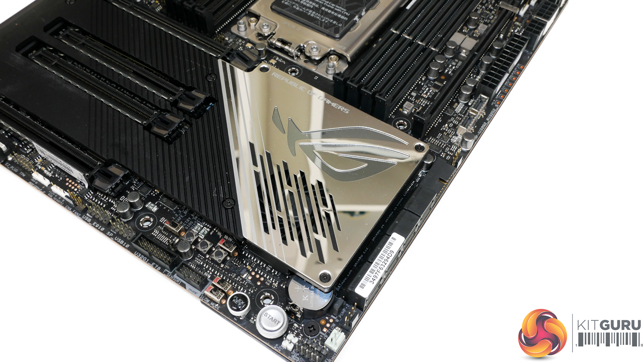
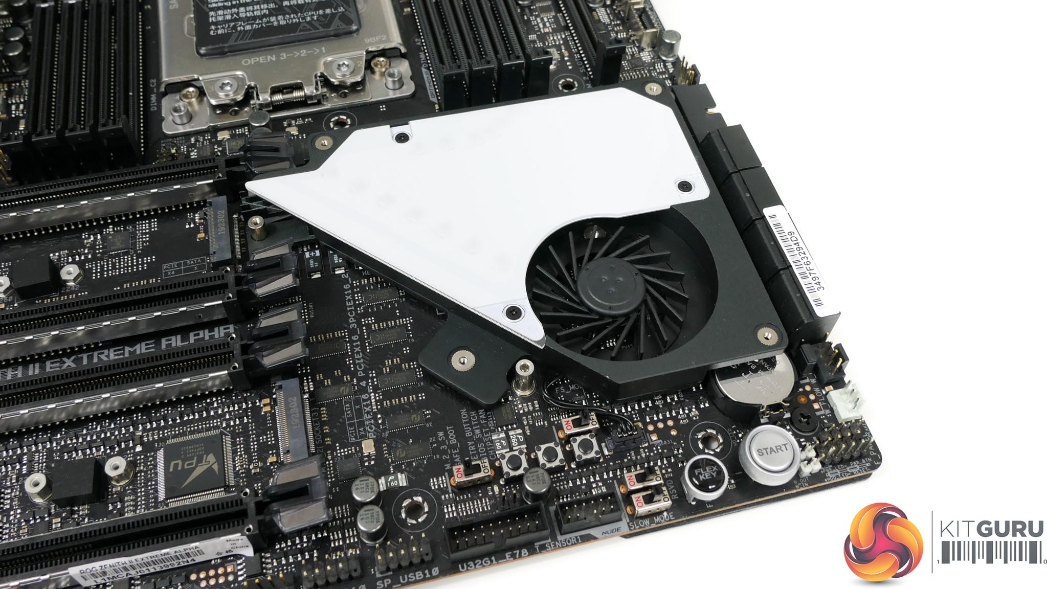
ASUS’ 40mm controllable chipset fan sits atop a metal cooling plate that features ample fins to dissipate heat from the TRX40 silicon. The fan is an open-rotor radial design that needs to force air across the well-sized fin stack in order to dissipate thermal energy effectively. Maximum RPM for the fan is around 4700 RPM within the BIOS. This level is loud but thankfully ASUS has good control options. By default, the fan does not spin at all when chipset temperature is below 55°C.
Incidental airflow for the radial fan is also routed towards the upper M.2 SSD nearby, which is a smart move by ASUS. Equally clever is ASUS’ application of a SoC power delivery component heatsink directly in the airflow path of the chipset fan.
Furthermore, positioning of the chipset fan is preferential as ASUS has made effort to position the blower as far away from a top-slot graphics card as is reasonably possible. This means that the small fan will be able to ingest air from the cool stream driven in by front chassis fans, with a lower amount of interference from the exhaust air exiting a hot graphics card cooler. Of course, that design logic is completely void if a user installs an open venting graphics card in any of the lower slots.