US9808385B2 - Lift-recliner chair - Google Patents

Lift-recliner chair Download PDF

Info

Publication number
US9808385B2
US9808385B2 US14/845,354 US201514845354A US9808385B2 US 9808385 B2 US9808385 B2 US 9808385B2 US 201514845354 A US201514845354 A US 201514845354A US 9808385 B2 US9808385 B2 US 9808385B2
Authority
US
United States
Prior art keywords
section
seat
backrest
chair
movement
Prior art date
Legal status (The legal status is an assumption and is not a legal conclusion. Google has not performed a legal analysis and makes no representation as to the accuracy of the status listed.)
Active, expires
Application number
US14/845,354
Other versions
US20150374566A1 (en
Inventor
Dale Robertson
Current Assignee (The listed assignees may be inaccurate. Google has not performed a legal analysis and makes no representation or warranty as to the accuracy of the list.)
Dewertokin Technology Group Co Ltd
Original Assignee
Integrated Furniture Technologies Ltd
Priority date (The priority date is an assumption and is not a legal conclusion. Google has not performed a legal analysis and makes no representation as to the accuracy of the date listed.)
Filing date
Publication date
Application filed by Integrated Furniture Technologies Ltd filed Critical Integrated Furniture Technologies Ltd
Priority to US14/845,354 priority Critical patent/US9808385B2/en
Assigned to INTEGRATED FURNITURE TECHNOLOGIES LIMITED reassignment INTEGRATED FURNITURE TECHNOLOGIES LIMITED ASSIGNMENT OF ASSIGNORS INTEREST (SEE DOCUMENT FOR DETAILS). Assignors: ROBERTSON, DALE
Priority to US14/972,975 priority patent/US10004334B2/en
Publication of US20150374566A1 publication Critical patent/US20150374566A1/en
Application granted granted Critical
Publication of US9808385B2 publication Critical patent/US9808385B2/en
Assigned to DEWERTOKIN GMBH reassignment DEWERTOKIN GMBH ASSIGNMENT OF ASSIGNORS INTEREST (SEE DOCUMENT FOR DETAILS). Assignors: INTEGRATED FURNITURE TECHNOLOGIES LTD.
Assigned to DEWERTOKIN TECHNOLOGY GROUP CO., LTD. reassignment DEWERTOKIN TECHNOLOGY GROUP CO., LTD. ASSIGNMENT OF ASSIGNORS INTEREST (SEE DOCUMENT FOR DETAILS). Assignors: DEWERTOKIN GMBH
Active legal-status Critical Current
Adjusted expiration legal-status Critical

Links

Images

Classifications

    • AHUMAN NECESSITIES
    • A61MEDICAL OR VETERINARY SCIENCE; HYGIENE
    • A61GTRANSPORT, PERSONAL CONVEYANCES, OR ACCOMMODATION SPECIALLY ADAPTED FOR PATIENTS OR DISABLED PERSONS; OPERATING TABLES OR CHAIRS; CHAIRS FOR DENTISTRY; FUNERAL DEVICES
    • A61G5/00Chairs or personal conveyances specially adapted for patients or disabled persons, e.g. wheelchairs
    • A61G5/10Parts, details or accessories
    • A61G5/14Standing-up or sitting-down aids
    • AHUMAN NECESSITIES
    • A47FURNITURE; DOMESTIC ARTICLES OR APPLIANCES; COFFEE MILLS; SPICE MILLS; SUCTION CLEANERS IN GENERAL
    • A47CCHAIRS; SOFAS; BEDS
    • A47C1/00Chairs adapted for special purposes
    • A47C1/02Reclining or easy chairs
    • A47C1/031Reclining or easy chairs having coupled concurrently adjustable supporting parts
    • A47C1/032Reclining or easy chairs having coupled concurrently adjustable supporting parts the parts being movably-coupled seat and back-rest

Definitions

  • This invention relates to powered lift-recliner chairs, and in particular concerns lift-recliner chairs of the type where the actuator and support arrangement for moving the adjustable parts of the chair is integrated into the structure of the chair.
  • Integrated lift-recliner chairs as disclosed in WO2005/051128 and WO2008/132482 typically comprise a number of relatively moveable sections including a floor standing base section, on angularly adjustable seat section, which is movable between a position in which it lies generally horizontally and a titled or inclined position in which it is raised to assist a user in moving from a seated position to a standing position, and an adjustable backrest section pivotally connected to the seat section.
  • the chair further comprises an adjustable foot rest.
  • the base and seat sections each include a pair of side panels arranged substantially parallel with each other on both sides of the chair to shield the actuator arrangement located in the interior of the chair.
  • the base and seat sections are arranged in a telescopic nesting configuration such that the seat section is telescopically extendable from the base section to raise and lower the chair.
  • each adjustable section is provided with a dedicated powered actuator, usually an electrical linear actuator or jack, for moving that section relative to the other sections of the chair.
  • the base and seat sections include respective actuator mounting brackets between which an actuator is mounted for moving the seat section relative to the base section about its pivot axis.
  • Actuator mounting brackets are also provided on the seat section and the backrest between which a second actuator is mounted for moving the backrest relative to the seat section.
  • the recliner function of the chair is provided by the operation of a dedicated actuator and the lift function is independently provided by a further dedicated actuator.
  • a lift-recliner chair comprising a floor standing base section, movable seat and backrest sections and actuator means for moving the seat and backrest sections, the seat section being pivotally mounted with respect to the base section and the backrest being pivotally mounted with respect to the seat section, characterised in that the said actuator means includes a single actuator for co-ordinated movement of both the seat and backrest sections.
  • a lift-recliner chair comprising a floor standing base section, movable seat and backrest sections and powered actuator means for moving the seat and backrest sections, the seat section being pivotally mounted with respect to the base section and the backrest being pivotally mounted with respect to the seat section, the base and seat sections each having a pair of side panels arranged substantially parallel with respect to each other on both sides of the chair with the actuator means being enclosed in the interior region of the chair between the side panels in all adjustment positions of the chair, the base and seat sections being arranged in a telescopic nesting configuration such that the seat section is telescopically moveable with respect to the base section to raise and lower the chair, characterised in that the said actuator means includes a single actuator for co-ordinated movement of both the seat and backrest sections.
  • the single actuator has a first range of movement for moving the backrest with respect to the seat section to provide the recliner function of the chair and a second range of movement for moving the seat section and backrest with respect to the base to provide the lift function of the chair.
  • the above aspects of the present invention are particularly advantageous as they employs only a single actuator, such as a powered motor or gas strut or spring for both the lift and recline functions of the chair. This reduces the cost of the chair significantly compared with prior art arrangements where two dedicated actuators are provided for the two separate functions of the chair. Thus there is a significant saving in manufacturing costs which affords wider appeal in the marketplace for the aforementioned type of lift-recliner chair.
  • a single actuator such as a powered motor or gas strut or spring for both the lift and recline functions of the chair.
  • the first and second ranges of movement are contiguous. In this way the second range of movement immediately follows the first.
  • movement of the actuator means in the first range exclusively moves the backrest with respect to the seat and base to provide the recliner function
  • movement of the actuator means in the second range exclusively moves the seat and backrest with respect to the base to provide the said lift function.
  • movement of the backrest with respect to the seat section is unfettered in the first range of movement. Movement of the backrest in the second range of movement is preferably prevented by engagement of respective engagement parts of the backrest and seat sections.
  • the engagement parts engage by mutual abutment as the actuator means moves from the first range to the second range, and the engagement parts disengage as the actuator moves from the second range to the first.
  • engagement and disengagement is simply and conveniently effected at the transition between the first and second ranges of the actuator movement.
  • At least one of the side panels of the seat section may include a slot which accommodates an engagement part of the backrest, which engagement part moves freely in the slot through the first range of movement and engages an abutment end of the slot at the transition between the first and second ranges of movement.
  • This provides a simple and compact arrangement for the purpose of providing both the lift and recline functions of the chair.
  • slots are provided in each of the respective seat section side panels for engagement with respective backrest engagement parts. In this way the loads applied to the backrest and seat sections by the actuator means can be readily applied on both sides of the chair.
  • the backrest includes a cross-member which extends between and through the slots, with the ends of the cross-member being accommodated in the respective slots.
  • the ends of the cross-member provide the backrest engagement parts on the sides of the choir.
  • the actuator is a preferably a linear actuator. Actuator loads can be minimised by selective placement of a linear actuator to maximise the turning moment applied to the movable sections of the chair.
  • the actuator is connected at one end to the base and at the other end to the backrest.
  • the actuator thus provides a connection between the base and the backrest.
  • the linear actuator maybe connected to the backrest cross-member. This readily enables actuator load to be applied first to the backrest in its first range of movement and then to the seat section, via engagement of the seat section with the backrest, in the second range of movement.
  • the base section including the respective base side panels, provides an outer frame of the choir and the seat section, including the respective seat side panels, on inner frame.
  • the seat frame nests within and is telescopically extendable from the base.
  • the base section constitutes the inner frame and the seat section the outer frame.
  • the backrest is pivotally connected directly to the side panels of the seat section.
  • the side panels of the seat section are pivotally connected to the base, preferably the side panels of the base, preferably by guide means including at least one guide associated with one of the seat or base and at least follower associated with the other of the seat and the base.
  • guide means including at least one guide associated with one of the seat or base and at least follower associated with the other of the seat and the base.
  • the side panels of the seat section may be pivotally connected to the side panels of the base by means of respective pivot pins, etc as shown in WO2005/051128.
  • FIG. 1 is perspective view from the front of a lift-recliner chair frame according to on embodiment of the present invention, with the chair frame shown in a fully raised position;
  • FIG. 2 is a perspective view from the rear of the chair frame of FIG. 1 with various side panels omitted for illustrative purposes;
  • FIG. 3 is a side view of the chair of FIG. 1 ;
  • FIG. 4 is a side view similar to FIG. 3 with a base section side panel omitted;
  • FIG. 5 is a partial side view of the chair frame, similar to FIG. 3 , with the choir in its fully reclined position;
  • FIG. 6 is a partial side view of the chair frame, similar to FIG. 4 , with the chair in its fully reclined position;
  • FIG. 7 is a perspective view from the front of a lift-recliner chair frame according to another embodiment of the present invention, with the frame shown in a fully raised position, with a side panel omitted for illustrative purposes only.
  • FIG. 8 is a side elevation view of the chair frame of FIG. 7 with all side panels attached;
  • FIG. 9 is side elevation view identical to FIG. 8 but with the base section side panel omitted;
  • FIG. 10 is a side elevation view identical to FIG. 9 with both the seat and base section side panels omitted.
  • FIGS. 1-6 show the structural arrangement and moving parts of a lift-recliner chair arrangement according to an embodiment of the present invention.
  • FIG. 1 is a perspective view of the structural frame 10 of a lift-recliner chair according to an embodiment of the present invention.
  • the frame is constructed principally from board material of the type typically used in the furniture industry, for example MDF or engineering board which is readily machinable on a CNC router or the like.
  • the frame 10 and hence the chair, includes a base support section 12 , a seat support section 14 , and a backrest section 16 .
  • the base section includes a pair of lateral side panels 18 and a rear panel (not shown) extending between the side panels at the rear of the chair.
  • the base section 12 constitutes the floor standing part of the chair and includes a pair of chassis legs in the form of elongate members 20 which extend parallel to each other on the lateral (left and right hand) sides of the chair.
  • the elongate members 20 are attached to the respective side panels 18 at the lower edges 22 thereof and extend outwards perpendicularly therefrom.
  • the chassis legs 20 constitute floor support members to which castors or the like may be attached for contact with the floor on which the chair is positioned.
  • the chassis legs are preferably constructed from the same board material as the rest of the frame 10 .
  • the side panels 18 are connected together at the front and rear of the chair by front and rear cross-members 24 and 26 which extend between the panels in the region of the panel bottom edges 22 , as can best be seen in FIG. 2 .
  • the cross-members 24 and 26 are of tubular metal construction and are provided with perpendicular mounting flanges 27 for attachment to the respective side panels 18 , typically by means of suitable fasteners such as screws or the like.
  • the side panels 18 , rear panel, elongate chassis legs 20 and cross-members define an outer open box like structure for supporting other parts of the chair.
  • the seat section 14 comprises a similar box type structure constructed primarily of board material and comprising a generally rectangular hollow frame 28 and a pair of lateral side panels 30 .
  • the seat frame 28 supports the seat pad (not shown) of the chair in a manner well known to those skilled in the art.
  • the lateral sides of the frame 28 are connected to the respective lateral side panels by suitable fixing means such as screws or the like.
  • the seat section 14 nests with the base section 12 and is pivotally connected thereto by a series of guides and followers in a similar manner to the arrangements disclosed in WO2005/132481, the contents of which are incorporated herein by reference.
  • Arcuate guide slots 32 are provided in the panels 18 and the slots receive a pair of spaced followers in the form of rollers 34 which are rotatably mounted on the adjacent seat section side panels 30 , extending on the outward facing side thereof. The rollers are free to run in the guide slots 32 .
  • the pivot axis of the seat section is defined by the centre of curvature of the concentric slots 32 .
  • the rear edges 36 of the seat section side panels 30 are arcuate and have a centre of curvature coincident with the centre of curvature of the slots 32 so that the rear part of the seat section can move freely, and in close proximity to, the rear panel (not shown) of the base section when the seat section is moved relative to the base section.
  • an end panel (not shown) which may be attached to the rear of the seat section at the rear edges 36 will also have a curvature which follows the curvature of the edges 36 so that the rear of the chair is enclosed by the seat section and base section end panels.
  • the width dimension of the seat section is slightly less than the width dimension of the base section so that the seat section nests within the base section and is extendable thereform when pivoted about its pivot axis to the raised position shown in FIGS. 1 to 4 .
  • the base section may be considered to comprise the outer frame of the chair and the seat section the inner frame of the nesting arrangement.
  • the present invention contemplates embodiments where the seat section forms the outer frame and the base section the inner frame.
  • the side panels 30 are each provided with a single accurate slot 38 positioned in the panel towards the rear edge 36 .
  • the purpose of this slot is significant to the understanding of the illustrated embodiment of the present invention and will be discussed in more detail below in relation to the operation of the backrest 16 and the lifting function of the chair.
  • the backrest 16 is constructed as a knock down type including a removable shaped frame 40 which is attached to connecting parts 42 of a pivot mounting arrangement which pivotally connects the backrest to the seat section at 44 .
  • the removable shaped frame is typical of a removable knock down backrest used in the furniture industry having female connecting parts 46 which receive corresponding male connecting parts or brackets 48 of the pivot mounting arrangement.
  • the pivot mounting arrangement is preferably of metal construction and comprises a tubular cross-member 50 which extends across the width of the chair with its ends disposed in the respective slots 38 .
  • the cross-member is disposed perpendicular to the side panels 30 and is pivotally connected to the respective side panels by a pair of lever arms 52 which extend parallel with the side panels 30 adjacent the interior facing surfaces thereof.
  • the levers are each provided with an upstanding pin which is received in a mounting bore in the side panel at 44 to pivotally connect the backrest to the movable seat section.
  • the connecting brackets 48 are positioned slightly inboard of the levers 52 on the cross-member 50 .
  • the cross-member 50 , lever arms 52 and connecting brackets 48 thus form a rigid structure and are preferably of metal construction joined together by welding.
  • An electrical linear actuator (jack) 53 is connected between the base section cross-member 24 and the backrest section cross-member 50 .
  • the linear actuator is connected at one end to mounting bracket 54 midway along the cross-member 24 and connected at the other end to mounting bracket 56 midway along the cross-member 50 such that extension and retraction of the actuator causes the backrest to be pivoted about its pivot axis and the seat section to be lifted.
  • FIGS. 1 to 4 the chair is fully raised to its lift position.
  • the single linear actuator 53 is at full extension.
  • the ends of the cross-member 50 abut the respective ends of the slots 38 .
  • the seat section is lowered as it moves about its pivot axis until a lower leg part 58 of the side panels contacts the cross-member 26 which prevents further movement of the seat section with respect to the base.
  • Further retraction of the linear actuator effects movement of the backrest about its pivot axis to recline the backrest with respect to the base and seat section to the fully reclined position shown in FIGS. 5 and 6 .
  • the actuator has two ranges of movement, first from a fully retracted condition where the backrest is fully reclined, as shown in FIGS. 5 and 6 , to an intermediate extension position where the backrest is moved to an upright position by movement of the cross-member 50 in the slots 38 , and a second range of movement from the aforementioned intermediate position to a fully extended position which causes the seal section to rotate about its pivot axis due to abutting engagement of the ends of the cross member with the ends of the slots 38 from the intermediate extension position onwards.
  • the linear actuator connected between the cross-member mounting brackets 54 and 56 provides the necessary force and hence motion for moving the backrest with respect to the seat and base sections to provide the recliner function and subsequently to move the backrest and seat section with respect to the base section to provide the lift function.
  • FIGS. 7 to 10 in a second embodiment of the present invention the lift-recliner chair is of the type described in WO2005/051128, the contents of which are incorporated herein by reference.
  • the lift-recliner chair of FIGS. 7 to 10 is substantially the same as that shown in FIGS. 1 to 6 apart from the pivot mounting arrangement between the seat section and the base section of the chair.
  • the seat section is pivotally connected to the base section by pivot pins 60 extending orthogonally from the side panels 30 of the seat section into receiving bores in the respective side panels 18 .
  • the pivot pins 60 define the pivot axis of the seat section and are positioned towards the front edge 62 of the side panels.
  • the pivot axis of the seal section is defined within the area of the side panels 18 , 30 whereas in the pivot arrangement of FIGS. 1 to 6 the pivot axis is not so constrained which allows the finished item of furniture to have a slightly different overall shape such as scalloped arms and a T-section seat cushion, for example, design features that are well known in the furniture industry.
  • FIGS. 7 to 10 the linear actuator 53 is present and connected between the brackets 54 and 56 .
  • the chair frame is shown in its fully raised position with the actuator 53 at full extension as previously described.
  • the side elevation drawings of FIGS. 8, 9 and 10 show the chair frame in progressively more detail with the side panels 18 and 30 progressively removed (omitted from the drawing) to reveal the internal detail of the chair.
  • FIG. 8 is a side view of the chair in its fully raised position with the side panels 18 and 30 in place.
  • FIG. 9 is a similar side view of the choir with the base section side panel 18 omitted for clarity to reveal the internal detail of the chair including the lower part of the actuator 53 attached to the bracket 54 .
  • FIG. 10 is a similar side view but with the seat section side panel 30 also removed showing the whole of the liner actuator 53 in its fully extended position.

Abstract

A lift-recliner chair includes a base section, movable seat and backrest sections and a powered actuator for relative moving the seat and backrest sections. The seat section is pivotally mounted with respect to the base section and the backrest is pivotally mounted with respect to the seat section. The base and seat sections each have a pair of side panels arranged substantially parallel with respect to each other on both sides of the chair with the actuator means enclosed in the interior region of the chair in all adjustment positions of the chair. The base and seat sections are arranged telescopically and moveable respect to the base section. The actuator has a first range of movement for moving the backrest with respect to the seat section and a second range of movement for moving the seat section and backrest with respect to the base.

Description

CROSS REFERENCE TO RELATED APPLICATIONS
This application relates to and is a continuation of U.S. Ser. No. 13/818,678 filed Apr. 29, 2013, the entire contents of which are incorporated by reference, which claims priority from PCT/GB/2011/001329 filed Sep. 9, 2011, the entire contents of which are incorporated herein by reference, which in turn claims priority to GB App. Ser. No. 1015084.5 filed Sep. 9, 2010.
This invention relates to powered lift-recliner chairs, and in particular concerns lift-recliner chairs of the type where the actuator and support arrangement for moving the adjustable parts of the chair is integrated into the structure of the chair.
Integrated lift-recliner chairs as disclosed in WO2005/051128 and WO2008/132482 typically comprise a number of relatively moveable sections including a floor standing base section, on angularly adjustable seat section, which is movable between a position in which it lies generally horizontally and a titled or inclined position in which it is raised to assist a user in moving from a seated position to a standing position, and an adjustable backrest section pivotally connected to the seat section. The chair further comprises an adjustable foot rest. The base and seat sections each include a pair of side panels arranged substantially parallel with each other on both sides of the chair to shield the actuator arrangement located in the interior of the chair. The base and seat sections are arranged in a telescopic nesting configuration such that the seat section is telescopically extendable from the base section to raise and lower the chair. Typically each adjustable section is provided with a dedicated powered actuator, usually an electrical linear actuator or jack, for moving that section relative to the other sections of the chair. In the lift recliner chair disclosed in FIG. 1 of WO2008/132482 the base and seat sections include respective actuator mounting brackets between which an actuator is mounted for moving the seat section relative to the base section about its pivot axis. Actuator mounting brackets are also provided on the seat section and the backrest between which a second actuator is mounted for moving the backrest relative to the seat section. In this arrangement and in the arrangements disclosed in WO2005/051128 the recliner function of the chair is provided by the operation of a dedicated actuator and the lift function is independently provided by a further dedicated actuator.
There is a requirement for an integrated type lift-recliner chair which has a simpler construction and reduced manufacturing costs compared with known designs.
According to an aspect of the present invention there is provided a lift-recliner chair comprising a floor standing base section, movable seat and backrest sections and actuator means for moving the seat and backrest sections, the seat section being pivotally mounted with respect to the base section and the backrest being pivotally mounted with respect to the seat section, characterised in that the said actuator means includes a single actuator for co-ordinated movement of both the seat and backrest sections.
According to another aspect of the invention there is provided a lift-recliner chair comprising a floor standing base section, movable seat and backrest sections and powered actuator means for moving the seat and backrest sections, the seat section being pivotally mounted with respect to the base section and the backrest being pivotally mounted with respect to the seat section, the base and seat sections each having a pair of side panels arranged substantially parallel with respect to each other on both sides of the chair with the actuator means being enclosed in the interior region of the chair between the side panels in all adjustment positions of the chair, the base and seat sections being arranged in a telescopic nesting configuration such that the seat section is telescopically moveable with respect to the base section to raise and lower the chair, characterised in that the said actuator means includes a single actuator for co-ordinated movement of both the seat and backrest sections.
Preferably, the single actuator has a first range of movement for moving the backrest with respect to the seat section to provide the recliner function of the chair and a second range of movement for moving the seat section and backrest with respect to the base to provide the lift function of the chair.
The above aspects of the present invention are particularly advantageous as they employs only a single actuator, such as a powered motor or gas strut or spring for both the lift and recline functions of the chair. This reduces the cost of the chair significantly compared with prior art arrangements where two dedicated actuators are provided for the two separate functions of the chair. Thus there is a significant saving in manufacturing costs which affords wider appeal in the marketplace for the aforementioned type of lift-recliner chair.
Preferably, the first and second ranges of movement are contiguous. In this way the second range of movement immediately follows the first.
In preferred embodiments movement of the actuator means in the first range exclusively moves the backrest with respect to the seat and base to provide the recliner function, and movement of the actuator means in the second range exclusively moves the seat and backrest with respect to the base to provide the said lift function. In this way there is a definite and immediate transition between recline and lift functions when the actuator is energised through its full range of movement, with the actuator acting either exclusively to recline the backrest or exclusively to lilt the seat section.
Preferably, movement of the backrest with respect to the seat section is unfettered in the first range of movement. Movement of the backrest in the second range of movement is preferably prevented by engagement of respective engagement parts of the backrest and seat sections. This provides a simple mechanical arrangement by which the two functions of the lift-recliner chair can be divided.
Preferably, the engagement parts engage by mutual abutment as the actuator means moves from the first range to the second range, and the engagement parts disengage as the actuator moves from the second range to the first. In this way engagement and disengagement is simply and conveniently effected at the transition between the first and second ranges of the actuator movement.
At least one of the side panels of the seat section may include a slot which accommodates an engagement part of the backrest, which engagement part moves freely in the slot through the first range of movement and engages an abutment end of the slot at the transition between the first and second ranges of movement. This provides a simple and compact arrangement for the purpose of providing both the lift and recline functions of the chair. In preferred embodiments slots are provided in each of the respective seat section side panels for engagement with respective backrest engagement parts. In this way the loads applied to the backrest and seat sections by the actuator means can be readily applied on both sides of the chair.
Preferably the backrest includes a cross-member which extends between and through the slots, with the ends of the cross-member being accommodated in the respective slots. In this way the ends of the cross-member provide the backrest engagement parts on the sides of the choir.
The actuator is a preferably a linear actuator. Actuator loads can be minimised by selective placement of a linear actuator to maximise the turning moment applied to the movable sections of the chair.
In preferred embodiments the actuator is connected at one end to the base and at the other end to the backrest. The actuator thus provides a connection between the base and the backrest.
The linear actuator maybe connected to the backrest cross-member. This readily enables actuator load to be applied first to the backrest in its first range of movement and then to the seat section, via engagement of the seat section with the backrest, in the second range of movement.
In preferred embodiments the base section, including the respective base side panels, provides an outer frame of the choir and the seat section, including the respective seat side panels, on inner frame. In this way the seat frame nests within and is telescopically extendable from the base. Aspects of the present invention also contemplate embodiments where the base section constitutes the inner frame and the seat section the outer frame.
Preferably, the backrest is pivotally connected directly to the side panels of the seat section.
The side panels of the seat section are pivotally connected to the base, preferably the side panels of the base, preferably by guide means including at least one guide associated with one of the seat or base and at least follower associated with the other of the seat and the base. In other embodiments the side panels of the seat section may be pivotally connected to the side panels of the base by means of respective pivot pins, etc as shown in WO2005/051128.
Various embodiments of the present invention will now be more particularly described, by way of example only, with reference to the accompanying drawings, in which:
FIG. 1 is perspective view from the front of a lift-recliner chair frame according to on embodiment of the present invention, with the chair frame shown in a fully raised position;
FIG. 2 is a perspective view from the rear of the chair frame of FIG. 1 with various side panels omitted for illustrative purposes;
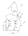
FIG. 3 is a side view of the chair of FIG. 1;
FIG. 4 is a side view similar to FIG. 3 with a base section side panel omitted;
FIG. 5 is a partial side view of the chair frame, similar to FIG. 3, with the choir in its fully reclined position;
FIG. 6 is a partial side view of the chair frame, similar to FIG. 4, with the chair in its fully reclined position;
FIG. 7 is a perspective view from the front of a lift-recliner chair frame according to another embodiment of the present invention, with the frame shown in a fully raised position, with a side panel omitted for illustrative purposes only.
FIG. 8 is a side elevation view of the chair frame of FIG. 7 with all side panels attached;
FIG. 9 is side elevation view identical to FIG. 8 but with the base section side panel omitted;
FIG. 10 is a side elevation view identical to FIG. 9 with both the seat and base section side panels omitted.
In the drawings the same reference numbers are used for same or similar parts.
Referring now to FIGS. 1-6 which show the structural arrangement and moving parts of a lift-recliner chair arrangement according to an embodiment of the present invention.
FIG. 1 is a perspective view of the structural frame 10 of a lift-recliner chair according to an embodiment of the present invention. The frame is constructed principally from board material of the type typically used in the furniture industry, for example MDF or engineering board which is readily machinable on a CNC router or the like.
The frame 10, and hence the chair, includes a base support section 12, a seat support section 14, and a backrest section 16. The base section includes a pair of lateral side panels 18 and a rear panel (not shown) extending between the side panels at the rear of the chair. The base section 12 constitutes the floor standing part of the chair and includes a pair of chassis legs in the form of elongate members 20 which extend parallel to each other on the lateral (left and right hand) sides of the chair. The elongate members 20 are attached to the respective side panels 18 at the lower edges 22 thereof and extend outwards perpendicularly therefrom. The chassis legs 20 constitute floor support members to which castors or the like may be attached for contact with the floor on which the chair is positioned. The chassis legs are preferably constructed from the same board material as the rest of the frame 10.
The side panels 18 are connected together at the front and rear of the chair by front and rear cross-members 24 and 26 which extend between the panels in the region of the panel bottom edges 22, as can best be seen in FIG. 2. The cross-members 24 and 26 are of tubular metal construction and are provided with perpendicular mounting flanges 27 for attachment to the respective side panels 18, typically by means of suitable fasteners such as screws or the like.
The side panels 18, rear panel, elongate chassis legs 20 and cross-members define an outer open box like structure for supporting other parts of the chair.
The seat section 14 comprises a similar box type structure constructed primarily of board material and comprising a generally rectangular hollow frame 28 and a pair of lateral side panels 30. The seat frame 28 supports the seat pad (not shown) of the chair in a manner well known to those skilled in the art. The lateral sides of the frame 28 are connected to the respective lateral side panels by suitable fixing means such as screws or the like.
The seat section 14 nests with the base section 12 and is pivotally connected thereto by a series of guides and followers in a similar manner to the arrangements disclosed in WO2005/132481, the contents of which are incorporated herein by reference. Arcuate guide slots 32 are provided in the panels 18 and the slots receive a pair of spaced followers in the form of rollers 34 which are rotatably mounted on the adjacent seat section side panels 30, extending on the outward facing side thereof. The rollers are free to run in the guide slots 32.
The pivot axis of the seat section is defined by the centre of curvature of the concentric slots 32. The rear edges 36 of the seat section side panels 30 are arcuate and have a centre of curvature coincident with the centre of curvature of the slots 32 so that the rear part of the seat section can move freely, and in close proximity to, the rear panel (not shown) of the base section when the seat section is moved relative to the base section. Similarly, an end panel (not shown) which may be attached to the rear of the seat section at the rear edges 36 will also have a curvature which follows the curvature of the edges 36 so that the rear of the chair is enclosed by the seat section and base section end panels.
It will be understood that the width dimension of the seat section is slightly less than the width dimension of the base section so that the seat section nests within the base section and is extendable thereform when pivoted about its pivot axis to the raised position shown in FIGS. 1 to 4. In this respect the base section may be considered to comprise the outer frame of the chair and the seat section the inner frame of the nesting arrangement. The present invention contemplates embodiments where the seat section forms the outer frame and the base section the inner frame.
The side panels 30 are each provided with a single accurate slot 38 positioned in the panel towards the rear edge 36. The purpose of this slot is significant to the understanding of the illustrated embodiment of the present invention and will be discussed in more detail below in relation to the operation of the backrest 16 and the lifting function of the chair.
The backrest 16 is constructed as a knock down type including a removable shaped frame 40 which is attached to connecting parts 42 of a pivot mounting arrangement which pivotally connects the backrest to the seat section at 44. The removable shaped frame is typical of a removable knock down backrest used in the furniture industry having female connecting parts 46 which receive corresponding male connecting parts or brackets 48 of the pivot mounting arrangement.
The pivot mounting arrangement is preferably of metal construction and comprises a tubular cross-member 50 which extends across the width of the chair with its ends disposed in the respective slots 38. The cross-member is disposed perpendicular to the side panels 30 and is pivotally connected to the respective side panels by a pair of lever arms 52 which extend parallel with the side panels 30 adjacent the interior facing surfaces thereof. The levers are each provided with an upstanding pin which is received in a mounting bore in the side panel at 44 to pivotally connect the backrest to the movable seat section. As can best be seen in the drawing of FIG. 1, the connecting brackets 48 are positioned slightly inboard of the levers 52 on the cross-member 50. The cross-member 50, lever arms 52 and connecting brackets 48 thus form a rigid structure and are preferably of metal construction joined together by welding.
An electrical linear actuator (jack) 53, as shown in the drawings of FIGS. 7 to 10 but omitted from the drawings of FIGS. 1-6, is connected between the base section cross-member 24 and the backrest section cross-member 50. The linear actuator is connected at one end to mounting bracket 54 midway along the cross-member 24 and connected at the other end to mounting bracket 56 midway along the cross-member 50 such that extension and retraction of the actuator causes the backrest to be pivoted about its pivot axis and the seat section to be lifted.
In the drawings of FIGS. 1 to 4 the chair is fully raised to its lift position. In this position the single linear actuator 53 is at full extension. In this position the ends of the cross-member 50 abut the respective ends of the slots 38. As the actuator is retracted the seat section is lowered as it moves about its pivot axis until a lower leg part 58 of the side panels contacts the cross-member 26 which prevents further movement of the seat section with respect to the base. Further retraction of the linear actuator effects movement of the backrest about its pivot axis to recline the backrest with respect to the base and seat section to the fully reclined position shown in FIGS. 5 and 6. In this way it will be understood that the actuator has two ranges of movement, first from a fully retracted condition where the backrest is fully reclined, as shown in FIGS. 5 and 6, to an intermediate extension position where the backrest is moved to an upright position by movement of the cross-member 50 in the slots 38, and a second range of movement from the aforementioned intermediate position to a fully extended position which causes the seal section to rotate about its pivot axis due to abutting engagement of the ends of the cross member with the ends of the slots 38 from the intermediate extension position onwards. Thus, the linear actuator connected between the cross-member mounting brackets 54 and 56 provides the necessary force and hence motion for moving the backrest with respect to the seat and base sections to provide the recliner function and subsequently to move the backrest and seat section with respect to the base section to provide the lift function.
Referring now to the drawings of FIGS. 7 to 10, in a second embodiment of the present invention the lift-recliner chair is of the type described in WO2005/051128, the contents of which are incorporated herein by reference. The lift-recliner chair of FIGS. 7 to 10 is substantially the same as that shown in FIGS. 1 to 6 apart from the pivot mounting arrangement between the seat section and the base section of the chair. In the second embodiment the seat section is pivotally connected to the base section by pivot pins 60 extending orthogonally from the side panels 30 of the seat section into receiving bores in the respective side panels 18. As can be seen in the drawings of FIGS. 7 to 10 the pivot pins 60 define the pivot axis of the seat section and are positioned towards the front edge 62 of the side panels. In this embodiment the pivot axis of the seal section is defined within the area of the side panels 18, 30 whereas in the pivot arrangement of FIGS. 1 to 6 the pivot axis is not so constrained which allows the finished item of furniture to have a slightly different overall shape such as scalloped arms and a T-section seat cushion, for example, design features that are well known in the furniture industry.
In the drawings of FIGS. 7 to 10 the linear actuator 53 is present and connected between the brackets 54 and 56. The chair frame is shown in its fully raised position with the actuator 53 at full extension as previously described. The side elevation drawings of FIGS. 8, 9 and 10 show the chair frame in progressively more detail with the side panels 18 and 30 progressively removed (omitted from the drawing) to reveal the internal detail of the chair. FIG. 8 is a side view of the chair in its fully raised position with the side panels 18 and 30 in place. FIG. 9 is a similar side view of the choir with the base section side panel 18 omitted for clarity to reveal the internal detail of the chair including the lower part of the actuator 53 attached to the bracket 54. FIG. 10 is a similar side view but with the seat section side panel 30 also removed showing the whole of the liner actuator 53 in its fully extended position.

Claims (22)

The invention claimed is:
1. A lift-recliner chair comprising:
a floor standing base section, a movable seat section and a movable backrest section and actuator means for moving the seat and backrest sections;
the seat section being pivotally mounted with respect to the base section and the backrest section being pivotally mounted with respect to the seat section;
wherein said actuator means is a single actuator for operative co-ordinated movement of both the seat and backrest sections, the single actuator being connected at one end to the base section and at the other end to the backrest section;
wherein an operative movement of the backrest section with respect to the seat section is unfettered in a first range of movement and is prevented in a second range of movement by a positive engagement of respective engagement parts of the backrest and seat sections, said engagement parts including at least a first engagement part fixed in relation to the seat section; and
wherein the engagement parts comprise ends of respective slots in the seat section and respective followers on the backrest section, and wherein the single actuator is connected to the backrest section, at least in part, through the respective followers such that the first range of movement comprises movement of the followers in the slots during movement of the backrest section relative to the seat section, and the second range of movement comprises movement of the backrest section and the seat section together relative to the base section when a force from the single actuator is applied to the ends of the slots via the followers.
2. A lift-recliner chair as claimed in claim 1, wherein:
said engagement parts include a second engagement part fixed in relation to the backrest section.
3. A lift-recliner chair as claimed in claim 1, wherein:
the single actuator has said first range of movement operative for moving the backrest section with respect to the seat section to provide a recliner function of the chair and said second range of movement operative for moving the seat section and backrest section with respect to the base section to provide a lift function of the chair.
4. A lift-recliner chair as claimed in claim 3, wherein:
the said first and second ranges of movement are contiguous.
5. A lift-recliner chair as claimed in claim 1, wherein:
a movement of the actuator means in said first range exclusively moves the backrest section with respect to the seat section and base section to provide said recliner function and movement of said actuator means in said second range exclusively moves the seat section and backrest section with respect to the base section to provide said lift function.
6. A lift chair as claimed in claim 1, wherein:
said engagement parts engage by mutual abutment as said actuator means moves from said first range to said second range, and said engagement parts disengage on a reverse transition thereof.
7. A lift-recliner chair as claimed in claim 1, wherein:
at least part of the seat section is provided with a slot which accommodates at least one of the engagement parts of the backrest section, which engagement part moves freely in the slot through the said first range of movement and engages an abutment end of the slot at a transition between said first and second ranges of movement.
8. A lift-recliner chair as claimed in claim 7, wherein:
slots are provided in respective seat section side panels and operative for engagement with respective backrest section engagement parts of the engagement parts.
9. A lift-recliner chair as claimed in claim 8, wherein:
said backrest section includes a cross-member which extends between said slots with the ends of the cross-member being accommodated in the respective slots operative to provide said backrest section engagement parts on both sides of the chair.
10. A lift-recliner chair as claimed in claim 1, wherein:
the said actuator is a linear actuator.
11. A lift-recliner chair as claimed in claim 10, wherein:
said actuator is secured at one end with respect to the said base section and at the other end with respect to the backrest section.
12. A lift-recliner hair as claimed in claim 10, wherein:
the said linear actuator is connected to the said backrest section cross-member.
13. A lift-recliner chair as claimed in claim 1, wherein:
the base and seat sections each have a pair of side panels arranged substantially parallel with respect to each other on both sides of the chair with the actuator means being enclosed in the interior region of the chair between the side panels in all adjustment positions of the chair, the base and seat sections being arranged in a telescopic nesting configuration such that the seat section is telescopically moveable with respect to the base section to raise and lower the chair.
14. A lift-recliner chair as claimed in claim 13, wherein:
said base section, including the respective base section side panels, provides an outer frame of the chair and the seat section, including the respective seat section side panels, an inner frame, such that the seat frame nests within and is telescopically extendable from the base section.
15. A lift-recliner as claimed in claim 13, wherein:
the backrest section is pivotally connected to the side panels of the seat section.
16. A lift-recliner as claimed in claim 13, wherein:
the side panels of the seat section are pivotally connected to the base section proximate said side panels by guide means; and
said guide means including at least one guide associated with one of the seat and the base sections and at least follower associated with the other of the seat and the base sections.
17. A method for operating a lift-recliner chair, comprising the steps of:
providing a floor standing base section, a movable seat section and a movable backrest section and operatively engaging an actuator means for moving the seat and backrest sections;
pivotally mounting the seat section with respect to the base section and pivotally mounting the backrest section with respect to the seat section;
providing in said actuator means a single actuator for operative co-ordinated movement of both the seat and backrest sections, the single actuator being connected at one end to the base section and at the other end to the backrest section; and
operating a movement of said backrest section with respect to the seat section in an unfettered manner through a first range of movement and preventing movement in a second range of movement by an engagement of respective engagement parts of the backrest and seat sections during a use thereof; and
providing said engagement parts with a first engagement part fixed in relation to the seat section; and
wherein the engagement parts comprise ends of respective slots in the seat section and respective followers on the backrest section, and wherein the single actuator is connected to the backrest section, at least in part, through the respective followers such that the first range of movement comprises movement of the followers in the slots during movement of the backrest section relative to the seat section, and the second range of movement comprises movement of the backrest section and the seat section together relative to the base section when a force from the single actuator is applied to the ends of the slots via the followers.
18. A method, as claimed in claim 17, further comprising the step of:
providing said engagement parts with a second engagement part fixed in relation to the backrest section;
the single actuator having said first range of movement operative for moving the backrest section with respect to the seat section to provide a recliner function of the chair and said second range of movement operative for moving the seat section and backrest section with respect to the base section to provide the lift function of the chair; and
the said first and second ranges of movement are contiguous during a use thereof.
19. A method, as claimed in claim 18, comprising the steps of:
providing a pair of side panels on each of the base and seat sections each arranged substantially parallel with respect to each other on both sides of the chair;
enclosing said actuator means in an interior region of the chair between the side panels in all adjustment positions of the chair;
arranging the base and seat sections in a telescopic nesting configuration such that the seat section is telescopically moveable with respect to the base section to raise and lower the chair during said use;
providing an outer frame of said chair with said base section including respective base section side panels;
providing an inner frame of said chair with said seat section including respective seat section side panels, such that the inner frame nests within and is telescopically extendable from the outer frame;
pivotally connecting the backrest section to the side panels of the seat section;
pivotally connecting the side panels of the seat section to the base section proximate said side panels by guide means; and
providing said guide means including at least one guide associated with at least one of said seat and said base sections and at least one follower associated with the other of said seat and said base sections during said use.
20. A lift-recliner chair chair comprising:
a floor standing base section;
a movable seat section;
a backrest section; and
an actuator means for moving the seat and backrest sections,
the seat section being pivotally mounted with respect to the base section;
the backrest section being pivotally mounted with respect to the seat section;
said actuator means being a single actuator for operative co-ordinated movement of both the seat section and the backrest section;
an operative movement of the backrest section with respect to the seat section being unfettered in a first range of movement and being prevented in a second range of movement by a positive engagement of respective engagement parts of the backrest section and the seat section;
at least part of the seat section being provided with a slot accommodating at least one of the engagement parts of the backrest section, said engagement part moving freely in the slot through said first range of movement and engaging an abutment end of the slot at a transition between said first and second ranges of movement.
21. A lift-recliner chair as claimed in claim 20, wherein:
slots are provided in respective seat section aside panels and operative for engagement with respective backrest section engagement parts of the engagement parts.
22. A lift-recliner chair as claimed in claim 20, wherein:
said backrest section includes a cross-member which extends between said slots with the ends of the cross-member being accommodated in the respective slots operative to provide said backrest section engagement parts on both sides of the chair.
US14/845,354 2010-09-09 2015-09-04 Lift-recliner chair Active 2031-09-29 US9808385B2 (en)

Priority Applications (2)

Application Number Priority Date Filing Date Title
US14/845,354 US9808385B2 (en) 2010-09-09 2015-09-04 Lift-recliner chair
US14/972,975 US10004334B2 (en) 2010-09-09 2015-12-17 Lift-recliner chair

Applications Claiming Priority (5)

Application Number Priority Date Filing Date Title
GB1015084.5 2010-09-09
GBGB1015084.5A GB201015084D0 (en) 2010-09-09 2010-09-09 Lift-recliner chair
PCT/GB2011/001329 WO2012032305A1 (en) 2010-09-09 2011-09-09 Lift-recliner chair
US201313818678A 2013-04-29 2013-04-29
US14/845,354 US9808385B2 (en) 2010-09-09 2015-09-04 Lift-recliner chair

Related Parent Applications (2)

Application Number Title Priority Date Filing Date
US13/818,678 Continuation US9155388B2 (en) 2010-09-09 2011-09-09 Lift-recliner chair and method thereof
PCT/GB2011/001329 Continuation WO2012032305A1 (en) 2010-09-09 2011-09-09 Lift-recliner chair

Related Child Applications (1)

Application Number Title Priority Date Filing Date
PCT/GB2014/000385 Continuation-In-Part WO2015044632A2 (en) 2010-09-09 2014-09-29 Lift-recliner chair

Publications (2)

Publication Number Publication Date
US20150374566A1 US20150374566A1 (en) 2015-12-31
US9808385B2 true US9808385B2 (en) 2017-11-07

Family

ID=43064993

Family Applications (2)

Application Number Title Priority Date Filing Date
US13/818,678 Active 2031-10-02 US9155388B2 (en) 2010-09-09 2011-09-09 Lift-recliner chair and method thereof
US14/845,354 Active 2031-09-29 US9808385B2 (en) 2010-09-09 2015-09-04 Lift-recliner chair

Family Applications Before (1)

Application Number Title Priority Date Filing Date
US13/818,678 Active 2031-10-02 US9155388B2 (en) 2010-09-09 2011-09-09 Lift-recliner chair and method thereof

Country Status (5)

Country Link
US (2) US9155388B2 (en)
EP (1) EP2613668B1 (en)
CN (1) CN103298373B (en)
GB (2) GB201015084D0 (en)
WO (1) WO2012032305A1 (en)

Cited By (6)

* Cited by examiner, † Cited by third party
Publication number Priority date Publication date Assignee Title
US10334951B2 (en) 2014-12-11 2019-07-02 Dewertokin Gmbh Adjustable furniture
US10405660B2 (en) 2009-08-18 2019-09-10 Dewertokin Gmbh Adjustable furniture
US20200060906A1 (en) * 2018-08-21 2020-02-27 Pride Mobility Products Corporation Adjustable lift chair frame
US10932584B2 (en) 2015-03-11 2021-03-02 Motus Mechanics Limited Adjustable bed
US11395549B2 (en) 2018-08-09 2022-07-26 Eevolv Ltd Drive mechanism
US11812857B2 (en) 2016-06-13 2023-11-14 Motus Mechanics Limited Adjustable furniture

Families Citing this family (15)

* Cited by examiner, † Cited by third party
Publication number Priority date Publication date Assignee Title
IL207236A (en) * 2010-07-21 2015-08-31 Moran Nadav Self assisting chair
US10004334B2 (en) 2010-09-09 2018-06-26 Integrated Furniture Technologies Limited Lift-recliner chair
GB201317259D0 (en) * 2013-09-30 2013-11-13 Integrated Furniture Technologies Ltd Lift-recliner chair
GB201015084D0 (en) 2010-09-09 2010-10-27 Integrated Furniture Technologies Ltd Lift-recliner chair
US9358167B2 (en) 2013-09-19 2016-06-07 La-Z-Boy Incorporated Furniture member power mechanism with selectable lift movement and zero gravity position
US9010851B2 (en) 2013-09-19 2015-04-21 La-Z-Boy Incorporated Furniture member power mechanism with selectable lift movement and zero gravity position
US9326606B2 (en) 2013-09-19 2016-05-03 La-Z-Boy Incorporated Furniture member power mechanism with zero gravity and rear tilt positions
GB2518394A (en) 2013-09-20 2015-03-25 Sherborne Upholstery Ltd Adjustable bed
US9468295B2 (en) * 2014-04-04 2016-10-18 L & P Property Management Company Zero-wall clearance linkage mechanism for a dual motor lifting recliner
US10045621B1 (en) * 2014-10-20 2018-08-14 James Norbert Welter Eternal chair
US10500112B1 (en) * 2017-06-09 2019-12-10 Wayne Harvey Hanson Dynamic support system for a chair to provide a user multiple supported positions
USD950971S1 (en) 2020-04-07 2022-05-10 Letronics, Inc. Lift chair with swivel and slide feature
CN111870442B (en) * 2020-08-03 2022-08-26 广州大学 A collapsible wheelchair for shifting disability crowd
CN214711596U (en) * 2020-12-31 2021-11-16 张孝兆 Headrest device and seat with same
CN113384407B (en) * 2021-07-31 2022-10-14 重庆理工大学 Wheelchair with auxiliary lifting and standing functions

Citations (42)

* Cited by examiner, † Cited by third party
Publication number Priority date Publication date Assignee Title
US349089A (en) * 1886-09-14 Invalid-lounge
US1414637A (en) 1921-01-04 1922-05-02 Gell Albert Edwin Reclining adjustable chair and seat
US3343871A (en) 1966-03-03 1967-09-26 George H Yates Automatically operated invalid chair
US3873152A (en) 1974-01-09 1975-03-25 John Garas Adjustable orthopedic lounger
GB1497973A (en) 1975-04-30 1978-01-12 Gaffney E Reclining elevator chair
JPS61181562A (en) 1984-11-07 1986-08-14 ジエ−、エム、フオイト、ゲゼルシヤフト、ミツト、ベシユレンクテル、ハフツング Apparatus for coating advancing web material
GB2227932A (en) 1988-12-28 1990-08-15 Ikeda Bussan Co Vehicular seat
US5024486A (en) * 1990-04-03 1991-06-18 Auel Carl C All-purpose rocking, swiveling, reclining, and lifting chair
US5219204A (en) * 1990-10-15 1993-06-15 Bathrick Leeland M Recliner and elevator chair
US5366036A (en) * 1993-01-21 1994-11-22 Perry Dale E Power stand-up and reclining wheelchair
US5466046A (en) 1988-05-20 1995-11-14 La-Z-Boy Chair Co. Linear actuation drive mechanism for power-assisted chairs
US5641201A (en) * 1993-03-02 1997-06-24 American Dream International Universal lift frame for a chair
WO1997027832A1 (en) 1996-02-01 1997-08-07 Robert Nicault Chair with a built-in standing aid device
DE29715343U1 (en) 1997-08-27 1997-11-27 Unimet Zentrallager Nord Gmbh Seating furniture, in particular garden armchairs
US5785384A (en) 1994-10-14 1998-07-28 Handicare Industri A/S Arrangement in an adjustable chair
DE29812763U1 (en) 1998-07-17 1998-09-10 Lusch Gmbh & Co Kg Ferd Armchair changeable in its seating position by a lifting device
US5806920A (en) 1994-11-17 1998-09-15 Blount; Eric D. Fully reclinable elevator lift chair with ottoman
EP0865960A1 (en) 1997-03-21 1998-09-23 Girsberger Holding AG Motor car seat
EP0891730A2 (en) 1997-07-16 1999-01-20 hülsta-werke Hüls GmbH & Co KG Slatted bed base with adjustable parts
US5992931A (en) * 1991-10-11 1999-11-30 La-Z-Boy Incorporated Modular power reclining chair
US6000758A (en) 1996-07-26 1999-12-14 Pride Health Care, Inc. Reclining lift chair
EP1050248A2 (en) 1999-05-06 2000-11-08 Edgtec Power actuated reclining chair with wall-hugger function
US20020125751A1 (en) 2001-02-08 2002-09-12 Bullard Larry I. Lift chair skirt
GB2380399A (en) 2001-04-03 2003-04-09 Graham Taylor Power operated lift reclining chair
US20040155504A1 (en) 2001-01-25 2004-08-12 Hirofumi Tada Reclining device
US20040212236A1 (en) 2001-08-03 2004-10-28 Hale Richard John Adjustable chairs and beds
WO2005051128A1 (en) 2003-10-30 2005-06-09 Robco Designs Ltd Adjustable reclining chair
EP1621173A2 (en) 2004-07-30 2006-02-01 Hill-Rom Services, Inc. Advanced articulation system and mattress support for a bed
WO2006023447A2 (en) 2004-08-16 2006-03-02 Hill-Rom Services, Inc. Chair
GB2418846A (en) 2004-10-07 2006-04-12 Alfred William Arthurs Chair incorporating a mechanism to assist rising
WO2008132482A1 (en) 2007-04-30 2008-11-06 James Walker & Co. Ltd. Hydrodynamic sealing element
DE102007024218A1 (en) 2007-05-11 2008-11-13 Appeltshauser, Georg, Dipl.-Ing. Seating furniture e.g. armchair, has head element adjustable as whole in height relative to seat part, where head element is adjustable by guide along carrier for head element, and guide runs curvedly in adjustment direction of head element
US7455360B2 (en) * 2006-04-21 2008-11-25 L & P Property Management Seating furniture with lift mechanism
GB2450199A (en) 2007-04-26 2008-12-17 Integrated Furniture Technology Reclining chair using arcuate guides and rollers
US7543885B2 (en) * 2004-09-13 2009-06-09 Golden Technologies, Inc. Lift chair and recliner
US7698761B2 (en) * 2008-02-04 2010-04-20 L&P Property Management Company Adjustable bed having four linear actuators
WO2011048384A1 (en) 2009-10-23 2011-04-28 Integrated Furniture Technologies Limited Adjustable furniture
WO2012032305A1 (en) 2010-09-09 2012-03-15 Integrated Furniture Technologies Limited Lift-recliner chair
GB2485424A (en) 2010-11-11 2012-05-16 Craig Price Method of adapting a vehicle having a screenwashing apparatus
WO2015044632A2 (en) * 2013-09-30 2015-04-02 Integrated Furniture Technologies Limited Lift-recliner chair
US9241571B2 (en) * 2009-08-18 2016-01-26 Integrated Furniture Technologies Limited Adjustable furniture
US9358167B2 (en) * 2013-09-19 2016-06-07 La-Z-Boy Incorporated Furniture member power mechanism with selectable lift movement and zero gravity position

Family Cites Families (38)

* Cited by examiner, † Cited by third party
Publication number Priority date Publication date Assignee Title
US638466A (en) 1899-09-30 1899-12-05 J A Kelly & Bros Inc Sofa-bedstead.
US912214A (en) 1908-07-18 1909-02-09 Lloyd W Ward Invalid-bed.
US942354A (en) 1909-06-14 1909-12-07 John G Ryan Head-rest for beds.
US1075154A (en) 1913-02-01 1913-10-07 George H Mansfield Snow-remover.
US1238078A (en) 1916-06-06 1917-08-28 Harvey N Ault Adjustable chair.
US2954072A (en) 1956-07-17 1960-09-27 Fossati Mario Hinged rods mechanism for reclinable armchairs
US3086814A (en) 1959-06-15 1963-04-23 Anton Lorenz Reclining chair of the multiple movement type
DE1404651C3 (en) 1959-09-17 1975-07-24 Fridtjof F. 1000 Berlin Schliephacke Reclining armchair with swiveling leg support
US3202453A (en) 1963-07-09 1965-08-24 Ford Motor Co Retractable seat
US3369767A (en) 1965-09-27 1968-02-20 Greenfield Company Seat belt retractor
EP0107882B1 (en) 1982-10-28 1986-07-23 FLIGHT EQUIPMENT & ENGINEERING LIMITED Vehicle seats
CN86104114A (en) * 1986-11-24 1988-06-08 曹明理 Multi-purpose bionic restored sofa
US5246266A (en) 1990-09-18 1993-09-21 Chairworks Taiwan Limited Chair
GB9425078D0 (en) 1994-12-13 1995-02-08 British Airways Plc A seating unit
US5897462A (en) 1997-04-18 1999-04-27 St. Germain; Robert J. Exercise apparatus
DE19906547B4 (en) 1999-02-17 2004-03-25 Innovint Einrichtungs Gmbh Child seat for mobile use in an aircraft
IT1306152B1 (en) 1999-06-02 2001-05-30 Aviointeriors Spa ARMCHAIR WITH PERFECTED CRADLE MOVEMENT, IN PARTICULAR AIRCRAFT.
US6347420B2 (en) 2000-04-12 2002-02-19 Franklin E. Elliott System for producing anthropometric, adjustable, articulated beds
AU9137401A (en) 2000-11-18 2002-05-23 Moon Ho Choi Safety device for car seat
WO2002076367A2 (en) 2001-03-27 2002-10-03 Hill-Rom Services, Inc. Hospital bed
ATE529293T1 (en) 2001-08-09 2011-11-15 Virgin Atlantic Airways Ltd A SEATING ARRANGEMENT AND A PASSENGER SEAT UNIT FOR AN AIRCRAFT
JP4902070B2 (en) 2001-08-22 2012-03-21 コンビ株式会社 child seat
JP2003310666A (en) 2002-04-23 2003-11-05 Tomi Mino Bed
US6739661B1 (en) 2002-07-15 2004-05-25 David N. Dukes Pivotable reclining child safety car seat
DE102005016943B4 (en) 2005-04-12 2006-11-30 Stanzwerk Wetter Sichelschmidt Gmbh & Co. Kg Ottoman
US20060238007A1 (en) * 2005-04-26 2006-10-26 Lin Chang C Chair with aid in lying back and getting up
EP1951547B1 (en) 2005-11-21 2015-07-08 Nightgear LLC Seating accessory
US7585018B2 (en) 2006-01-10 2009-09-08 La-Z-Boy Incorporated Wall proximity reclining chair with in-line linkage mechanism
US7703851B2 (en) 2006-09-21 2010-04-27 Mazda Motor Corporation Seat device
US7445279B2 (en) 2006-11-13 2008-11-04 L & P Property Management Company Pivot-over-arm reclining mechanism for a seating unit
US7766421B2 (en) 2006-12-21 2010-08-03 L & P Property Management Company Recliner lift chair with power lift and reclining units
GB0704546D0 (en) 2007-03-08 2007-04-18 Contour Premium Aircraft Seati Adjustable seat
KR101544225B1 (en) 2007-05-05 2015-08-12 바스프 에스이 Ionic liquids comprising polyethercarboxylates as anions production and use thereof
US8226162B2 (en) 2009-09-11 2012-07-24 Campbell Corey A Child safety seat
US8308228B2 (en) * 2010-02-11 2012-11-13 L & P Property Management Company Zero-wall clearance linkage mechanism for a lifting recliner
US8403415B2 (en) 2010-08-16 2013-03-26 Be Aerospace, Inc. Aircraft passenger seat recline mechanism
US8534758B2 (en) 2010-09-13 2013-09-17 Tropitone Furniture Co., Inc. Reclinable seating apparatus and method
GB2496597B (en) 2011-11-14 2017-10-04 Bio-Check(Uk) Ltd Cartridge for containing a sample

Patent Citations (49)

* Cited by examiner, † Cited by third party
Publication number Priority date Publication date Assignee Title
US349089A (en) * 1886-09-14 Invalid-lounge
US1414637A (en) 1921-01-04 1922-05-02 Gell Albert Edwin Reclining adjustable chair and seat
US3343871A (en) 1966-03-03 1967-09-26 George H Yates Automatically operated invalid chair
US3873152A (en) 1974-01-09 1975-03-25 John Garas Adjustable orthopedic lounger
GB1497973A (en) 1975-04-30 1978-01-12 Gaffney E Reclining elevator chair
JPS61181562A (en) 1984-11-07 1986-08-14 ジエ−、エム、フオイト、ゲゼルシヤフト、ミツト、ベシユレンクテル、ハフツング Apparatus for coating advancing web material
US5466046A (en) 1988-05-20 1995-11-14 La-Z-Boy Chair Co. Linear actuation drive mechanism for power-assisted chairs
GB2227932A (en) 1988-12-28 1990-08-15 Ikeda Bussan Co Vehicular seat
US5024486A (en) * 1990-04-03 1991-06-18 Auel Carl C All-purpose rocking, swiveling, reclining, and lifting chair
US5219204A (en) * 1990-10-15 1993-06-15 Bathrick Leeland M Recliner and elevator chair
US5992931A (en) * 1991-10-11 1999-11-30 La-Z-Boy Incorporated Modular power reclining chair
US5366036A (en) * 1993-01-21 1994-11-22 Perry Dale E Power stand-up and reclining wheelchair
US5641201A (en) * 1993-03-02 1997-06-24 American Dream International Universal lift frame for a chair
US5785384A (en) 1994-10-14 1998-07-28 Handicare Industri A/S Arrangement in an adjustable chair
US5806920A (en) 1994-11-17 1998-09-15 Blount; Eric D. Fully reclinable elevator lift chair with ottoman
WO1997027832A1 (en) 1996-02-01 1997-08-07 Robert Nicault Chair with a built-in standing aid device
US6000758A (en) 1996-07-26 1999-12-14 Pride Health Care, Inc. Reclining lift chair
EP0865960A1 (en) 1997-03-21 1998-09-23 Girsberger Holding AG Motor car seat
EP0891730A2 (en) 1997-07-16 1999-01-20 hülsta-werke Hüls GmbH & Co KG Slatted bed base with adjustable parts
DE29715343U1 (en) 1997-08-27 1997-11-27 Unimet Zentrallager Nord Gmbh Seating furniture, in particular garden armchairs
DE29812763U1 (en) 1998-07-17 1998-09-10 Lusch Gmbh & Co Kg Ferd Armchair changeable in its seating position by a lifting device
EP1050248A2 (en) 1999-05-06 2000-11-08 Edgtec Power actuated reclining chair with wall-hugger function
US20020063459A1 (en) 1999-05-06 2002-05-30 Edward J. Gaffney Power actuated reclining chair with wall-hugger function
US20040155504A1 (en) 2001-01-25 2004-08-12 Hirofumi Tada Reclining device
US20020125751A1 (en) 2001-02-08 2002-09-12 Bullard Larry I. Lift chair skirt
US6702378B2 (en) * 2001-02-08 2004-03-09 L & P Property Management Company Lift chair skirt
GB2380399A (en) 2001-04-03 2003-04-09 Graham Taylor Power operated lift reclining chair
US20040212236A1 (en) 2001-08-03 2004-10-28 Hale Richard John Adjustable chairs and beds
US7631937B2 (en) * 2003-10-30 2009-12-15 Robco Designs Ltd. Powered furniture
WO2005051128A1 (en) 2003-10-30 2005-06-09 Robco Designs Ltd Adjustable reclining chair
US7699389B2 (en) 2003-10-30 2010-04-20 Roboco Design Ltd. Powered furniture
US7575279B2 (en) 2003-10-30 2009-08-18 Robco Designs Ltd. Adjustable reclining chair
EP1621173A2 (en) 2004-07-30 2006-02-01 Hill-Rom Services, Inc. Advanced articulation system and mattress support for a bed
WO2006023447A2 (en) 2004-08-16 2006-03-02 Hill-Rom Services, Inc. Chair
US7543885B2 (en) * 2004-09-13 2009-06-09 Golden Technologies, Inc. Lift chair and recliner
GB2418846A (en) 2004-10-07 2006-04-12 Alfred William Arthurs Chair incorporating a mechanism to assist rising
US7455360B2 (en) * 2006-04-21 2008-11-25 L & P Property Management Seating furniture with lift mechanism
GB2450199A (en) 2007-04-26 2008-12-17 Integrated Furniture Technology Reclining chair using arcuate guides and rollers
WO2008132482A1 (en) 2007-04-30 2008-11-06 James Walker & Co. Ltd. Hydrodynamic sealing element
DE102007024218A1 (en) 2007-05-11 2008-11-13 Appeltshauser, Georg, Dipl.-Ing. Seating furniture e.g. armchair, has head element adjustable as whole in height relative to seat part, where head element is adjustable by guide along carrier for head element, and guide runs curvedly in adjustment direction of head element
US7698761B2 (en) * 2008-02-04 2010-04-20 L&P Property Management Company Adjustable bed having four linear actuators
US9241571B2 (en) * 2009-08-18 2016-01-26 Integrated Furniture Technologies Limited Adjustable furniture
US20160120315A1 (en) * 2009-08-18 2016-05-05 Integrated Furniture Technologies Limited Adjustable furniture
WO2011048384A1 (en) 2009-10-23 2011-04-28 Integrated Furniture Technologies Limited Adjustable furniture
WO2012032305A1 (en) 2010-09-09 2012-03-15 Integrated Furniture Technologies Limited Lift-recliner chair
GB2485424A (en) 2010-11-11 2012-05-16 Craig Price Method of adapting a vehicle having a screenwashing apparatus
US9358167B2 (en) * 2013-09-19 2016-06-07 La-Z-Boy Incorporated Furniture member power mechanism with selectable lift movement and zero gravity position
WO2015044632A2 (en) * 2013-09-30 2015-04-02 Integrated Furniture Technologies Limited Lift-recliner chair
GB2520812A (en) * 2013-09-30 2015-06-03 Integrated Furniture Technologies Ltd Lift-recliner chair

Non-Patent Citations (7)

* Cited by examiner, † Cited by third party
Title
Combined Search and Examination report for GB 1013879.0, dated Dec. 7, 2010 (6 pages).
International Search Report and Written Opinion for PCT/GB2008/001504 dated Sep. 24, 2008.
International Search Report for PCT/GB2010/001565 dated May 26, 2011, 6 pages.
International Search Report for PCT/GB2010/001961 dated Nov. 2, 2011, 2 pages.
PCT/GB2011/001329 International Search Report dated Feb. 2, 2012, 3 pages-English.
PCT/GB2011/001329 International Search Report dated Feb. 2, 2012, 3 pages—English.
U.S. Appl. No. 13/380,985, filed Feb. 2012, Robertson.

Cited By (8)

* Cited by examiner, † Cited by third party
Publication number Priority date Publication date Assignee Title
US10405660B2 (en) 2009-08-18 2019-09-10 Dewertokin Gmbh Adjustable furniture
US10334951B2 (en) 2014-12-11 2019-07-02 Dewertokin Gmbh Adjustable furniture
US10932584B2 (en) 2015-03-11 2021-03-02 Motus Mechanics Limited Adjustable bed
US11812857B2 (en) 2016-06-13 2023-11-14 Motus Mechanics Limited Adjustable furniture
US11395549B2 (en) 2018-08-09 2022-07-26 Eevolv Ltd Drive mechanism
US20200060906A1 (en) * 2018-08-21 2020-02-27 Pride Mobility Products Corporation Adjustable lift chair frame
US10632031B2 (en) * 2018-08-21 2020-04-28 Pride Mobility Products Corporation Adjustable lift chair frame
US10925787B2 (en) 2018-08-21 2021-02-23 Pride Mobility Products Corporation Adjustable lift chair frame

Also Published As

Publication number Publication date
CN103298373A (en) 2013-09-11
GB201015084D0 (en) 2010-10-27
US20150374566A1 (en) 2015-12-31
GB201115686D0 (en) 2011-10-26
US9155388B2 (en) 2015-10-13
EP2613668A1 (en) 2013-07-17
GB2485434A (en) 2012-05-16
GB2485434B (en) 2013-03-20
EP2613668B1 (en) 2017-12-27
CN103298373B (en) 2018-07-17
US20140035336A1 (en) 2014-02-06
WO2012032305A1 (en) 2012-03-15

Similar Documents

Publication Publication Date Title
US9808385B2 (en) Lift-recliner chair
US10004334B2 (en) Lift-recliner chair
US10334951B2 (en) Adjustable furniture
US7735912B2 (en) Powered furniture
EP3051979B1 (en) Lift-recliner chair
JP3219621U (en) Electric stand-up assist reclining chair
US20230016779A1 (en) Sofa bed with glide system
US5653502A (en) Foldable chair
CN102917620A (en) Convertible furniture item
CN113453585B (en) adjustable chair
US20070252422A1 (en) Seating unit convertible into chaise
US7669922B2 (en) Reclining seating unit with backrest support frame
CN212437950U (en) Linkage type geriatric chair framework structure and geriatric chair
US20050146167A1 (en) Recliner
GB2331007A (en) A reclining chair with a seat back portion not extending backwards when tilted
ITMI991285A1 (en) STRUCTURE FOR SOFA BEDS AND SIMILAR

Legal Events

Date Code Title Description
AS Assignment

Owner name: INTEGRATED FURNITURE TECHNOLOGIES LIMITED, UNITED

Free format text: ASSIGNMENT OF ASSIGNORS INTEREST;ASSIGNOR:ROBERTSON, DALE;REEL/FRAME:036508/0378

Effective date: 20130425

STCF Information on status: patent grant

Free format text: PATENTED CASE

AS Assignment

Owner name: DEWERTOKIN GMBH, GERMANY

Free format text: ASSIGNMENT OF ASSIGNORS INTEREST;ASSIGNOR:INTEGRATED FURNITURE TECHNOLOGIES LTD.;REEL/FRAME:049060/0001

Effective date: 20190311

MAFP Maintenance fee payment

Free format text: PAYMENT OF MAINTENANCE FEE, 4TH YEAR, LARGE ENTITY (ORIGINAL EVENT CODE: M1551); ENTITY STATUS OF PATENT OWNER: LARGE ENTITY

Year of fee payment: 4

AS Assignment

Owner name: DEWERTOKIN TECHNOLOGY GROUP CO., LTD., CHINA

Free format text: ASSIGNMENT OF ASSIGNORS INTEREST;ASSIGNOR:DEWERTOKIN GMBH;REEL/FRAME:056527/0809

Effective date: 20201231