US9804031B2 - Apparatus and method to calculate energy dissipated from an object - Google Patents
Apparatus and method to calculate energy dissipated from an object Download PDFInfo
- Publication number
- US9804031B2 US9804031B2 US14/470,762 US201414470762A US9804031B2 US 9804031 B2 US9804031 B2 US 9804031B2 US 201414470762 A US201414470762 A US 201414470762A US 9804031 B2 US9804031 B2 US 9804031B2
- Authority
- US
- United States
- Prior art keywords
- camera
- value
- thermal radiation
- imaged view
- radiation data
- Prior art date
- Legal status (The legal status is an assumption and is not a legal conclusion. Google has not performed a legal analysis and makes no representation as to the accuracy of the status listed.)
- Active, expires
Links
- 238000000034 method Methods 0.000 title claims abstract description 34
- 230000005855 radiation Effects 0.000 claims abstract description 102
- 230000004044 response Effects 0.000 claims abstract description 9
- 238000012545 processing Methods 0.000 abstract description 142
- 238000004364 calculation method Methods 0.000 description 20
- 230000003750 conditioning effect Effects 0.000 description 15
- 238000009529 body temperature measurement Methods 0.000 description 11
- 238000012546 transfer Methods 0.000 description 11
- 238000005259 measurement Methods 0.000 description 6
- 238000004590 computer program Methods 0.000 description 5
- 230000005055 memory storage Effects 0.000 description 5
- XLYOFNOQVPJJNP-UHFFFAOYSA-N water Substances O XLYOFNOQVPJJNP-UHFFFAOYSA-N 0.000 description 3
- 238000004458 analytical method Methods 0.000 description 2
- 230000001419 dependent effect Effects 0.000 description 2
- 241000272496 Galliformes Species 0.000 description 1
- XMQFTWRPUQYINF-UHFFFAOYSA-N bensulfuron-methyl Chemical compound COC(=O)C1=CC=CC=C1CS(=O)(=O)NC(=O)NC1=NC(OC)=CC(OC)=N1 XMQFTWRPUQYINF-UHFFFAOYSA-N 0.000 description 1
- 238000004422 calculation algorithm Methods 0.000 description 1
- 238000012937 correction Methods 0.000 description 1
- 230000008878 coupling Effects 0.000 description 1
- 238000010168 coupling process Methods 0.000 description 1
- 238000005859 coupling reaction Methods 0.000 description 1
- 238000009429 electrical wiring Methods 0.000 description 1
- 238000005265 energy consumption Methods 0.000 description 1
- 238000005516 engineering process Methods 0.000 description 1
- 238000011156 evaluation Methods 0.000 description 1
- 230000006870 function Effects 0.000 description 1
- 238000003709 image segmentation Methods 0.000 description 1
- 238000003384 imaging method Methods 0.000 description 1
- 239000003550 marker Substances 0.000 description 1
- 239000011159 matrix material Substances 0.000 description 1
- 238000012805 post-processing Methods 0.000 description 1
Images


Classifications
-
- G—PHYSICS
- G01—MEASURING; TESTING
- G01J—MEASUREMENT OF INTENSITY, VELOCITY, SPECTRAL CONTENT, POLARISATION, PHASE OR PULSE CHARACTERISTICS OF INFRARED, VISIBLE OR ULTRAVIOLET LIGHT; COLORIMETRY; RADIATION PYROMETRY
- G01J5/00—Radiation pyrometry, e.g. infrared or optical thermometry
- G01J5/02—Constructional details
- G01J5/025—Interfacing a pyrometer to an external device or network; User interface
-
- G—PHYSICS
- G01—MEASURING; TESTING
- G01J—MEASUREMENT OF INTENSITY, VELOCITY, SPECTRAL CONTENT, POLARISATION, PHASE OR PULSE CHARACTERISTICS OF INFRARED, VISIBLE OR ULTRAVIOLET LIGHT; COLORIMETRY; RADIATION PYROMETRY
- G01J5/00—Radiation pyrometry, e.g. infrared or optical thermometry
- G01J5/02—Constructional details
- G01J5/06—Arrangements for eliminating effects of disturbing radiation; Arrangements for compensating changes in sensitivity
- G01J5/064—Ambient temperature sensor; Housing temperature sensor; Constructional details thereof
-
- G—PHYSICS
- G01—MEASURING; TESTING
- G01J—MEASUREMENT OF INTENSITY, VELOCITY, SPECTRAL CONTENT, POLARISATION, PHASE OR PULSE CHARACTERISTICS OF INFRARED, VISIBLE OR ULTRAVIOLET LIGHT; COLORIMETRY; RADIATION PYROMETRY
- G01J5/00—Radiation pyrometry, e.g. infrared or optical thermometry
- G01J5/10—Radiation pyrometry, e.g. infrared or optical thermometry using electric radiation detectors
-
- G—PHYSICS
- G02—OPTICS
- G02B—OPTICAL ELEMENTS, SYSTEMS OR APPARATUS
- G02B13/00—Optical objectives specially designed for the purposes specified below
- G02B13/14—Optical objectives specially designed for the purposes specified below for use with infrared or ultraviolet radiation
-
- H—ELECTRICITY
- H04—ELECTRIC COMMUNICATION TECHNIQUE
- H04N—PICTORIAL COMMUNICATION, e.g. TELEVISION
- H04N5/00—Details of television systems
- H04N5/30—Transforming light or analogous information into electric information
- H04N5/33—Transforming infrared radiation
-
- G—PHYSICS
- G01—MEASURING; TESTING
- G01J—MEASUREMENT OF INTENSITY, VELOCITY, SPECTRAL CONTENT, POLARISATION, PHASE OR PULSE CHARACTERISTICS OF INFRARED, VISIBLE OR ULTRAVIOLET LIGHT; COLORIMETRY; RADIATION PYROMETRY
- G01J5/00—Radiation pyrometry, e.g. infrared or optical thermometry
- G01J2005/0077—Imaging
-
- G01J2005/0085—
-
- G01J2005/068—
-
- G—PHYSICS
- G01—MEASURING; TESTING
- G01J—MEASUREMENT OF INTENSITY, VELOCITY, SPECTRAL CONTENT, POLARISATION, PHASE OR PULSE CHARACTERISTICS OF INFRARED, VISIBLE OR ULTRAVIOLET LIGHT; COLORIMETRY; RADIATION PYROMETRY
- G01J5/00—Radiation pyrometry, e.g. infrared or optical thermometry
- G01J5/02—Constructional details
- G01J5/0275—Control or determination of height or distance or angle information for sensors or receivers
-
- G—PHYSICS
- G01—MEASURING; TESTING
- G01J—MEASUREMENT OF INTENSITY, VELOCITY, SPECTRAL CONTENT, POLARISATION, PHASE OR PULSE CHARACTERISTICS OF INFRARED, VISIBLE OR ULTRAVIOLET LIGHT; COLORIMETRY; RADIATION PYROMETRY
- G01J5/00—Radiation pyrometry, e.g. infrared or optical thermometry
- G01J5/48—Thermography; Techniques using wholly visual means
- G01J5/485—Temperature profile
-
- G—PHYSICS
- G01—MEASURING; TESTING
- G01S—RADIO DIRECTION-FINDING; RADIO NAVIGATION; DETERMINING DISTANCE OR VELOCITY BY USE OF RADIO WAVES; LOCATING OR PRESENCE-DETECTING BY USE OF THE REFLECTION OR RERADIATION OF RADIO WAVES; ANALOGOUS ARRANGEMENTS USING OTHER WAVES
- G01S17/00—Systems using the reflection or reradiation of electromagnetic waves other than radio waves, e.g. lidar systems
- G01S17/02—Systems using the reflection of electromagnetic waves other than radio waves
- G01S17/06—Systems determining position data of a target
- G01S17/08—Systems determining position data of a target for measuring distance only
-
- G—PHYSICS
- G01—MEASURING; TESTING
- G01S—RADIO DIRECTION-FINDING; RADIO NAVIGATION; DETERMINING DISTANCE OR VELOCITY BY USE OF RADIO WAVES; LOCATING OR PRESENCE-DETECTING BY USE OF THE REFLECTION OR RERADIATION OF RADIO WAVES; ANALOGOUS ARRANGEMENTS USING OTHER WAVES
- G01S17/00—Systems using the reflection or reradiation of electromagnetic waves other than radio waves, e.g. lidar systems
- G01S17/88—Lidar systems specially adapted for specific applications
Definitions
- the present technology relates in general to IR cameras and methods for use in a processing unit of IR cameras, in particular to IR camera and methods for capturing IR radiation data of an imaged view.
- Infrared thermal cameras can be used in a number of different situations, for example, when inspecting or surveying complex electrical systems such as transformers, switchgears etc., or water carrying systems such as heat exchangers, radiators etc. IR cameras are used for capturing and storing thermal radiation data. This thermal radiation data may then be displayed and viewed as thermal images and analyzed in order to, for example, find faulty electrical wirings or couplings, leaking water pipes, etc.
- thermal radiation data and/or the thermal images of the IR camera various procedures and methods are being used in order to properly analyse the thermal radiation data and/or the thermal images of the IR camera, and these are not necessarily particularly intuitive and easily understandable by a user of the IR camera.
- the analysis of the thermal radiation data and/or the thermal images of an IR camera may also be a time-consuming task and may thus preclude a user of an IR camera from making decisions, predictions, and/or recommendations to clients while being on site and performing the IR imaging.
- an IR camera comprises: a thermal radiation capturing arrangement for capturing thermal radiation of an imaged view in response to an input control unit(s) receiving inputs from a user of the IR camera; a processing unit arranged to process the thermal radiation data in order for the thermal radiation data to be displayed by an IR camera display as thermal images; and an IR camera display arranged to display thermal images to a user of the IR camera.
- the processing unit of the IR camera may be further arranged to: determine at least one temperature reference value representing the temperature of the surrounding environment of the imaged view; and calculate at least one output power value indicative of an amount of energy dissipated in a part of the imaged view by using the temperature value of the thermal radiation data corresponding to said part of the imaged view and the at least one determined temperature reference value.
- the exemplary embodiment may increase usability to a user of an IR camera when analysing the thermal images of the IR camera by enabling a calculation of the output power dissipated in an imaged view. This also allows a user of the IR camera to achieve an estimate of the energy properties of an imaged view in a simple and easy manner.
- the processing unit of the IR camera may also be arranged to control the IR camera display to display the at least one calculated output power value to a user of the IR camera in place of the corresponding temperature pixel in the thermal image. This enables the user of the IR camera to monitor the outputted power density of the energy radiating from an imaged view directly in the IR camera display as the object is being imaged by the IR camera.
- the processing unit of the IR camera may also be arranged to determine a first subset of the thermal radiation data as a thermal image object area representing an object in the imaged view for which an output power value is to be determined; and calculate an object output power value indicative of the amount of energy outputted from the object in the imaged view based upon output power values of the determined thermal image object area in the thermal radiation data.
- This may provide increased usability to a user of an IR camera when analysing the thermal images of the IR camera by enabling a calculation of the output power radiating from an object in an imaged view. This also allows a user of the IR camera to achieve an estimate of the energy properties of an imaged object in a simple and easy manner
- the processing unit of the IR camera may also be arranged to control the IR camera display to display the calculated object output power value to a user of the IR camera together with the thermal images. This enables the user of the IR camera to monitor the output power radiating from an object directly in the IR camera display as the object is being imaged by the IR camera.
- the processing unit of the IR camera may also be arranged to receive information comprising current energy price information and time span information. This may be performed by the user of the IR camera using the input control devices.
- an estimated cost of the total energy consumption may be based on the received current energy price information and the outputted energy. This cost estimate may then be displayed by the IR camera display to the user of the IR camera together with the thermal images, such that a fast and efficient energy cost evaluation for the object may be performed immediately on site.
- the processing unit of the IR camera may further be arranged to determine the thermal image object area in the thermal radiation data by receiving information from the input control unit(s) indicating a subset of the thermal radiation data as the thermal image object area.
- This allows a user of the IR camera to manually indicate an area in the displayed IR thermal images of the IR camera display representing the object for which the user of the IR camera desires the output power to be determined; the indicated area will correlate to a particular subset of the thermal radiation data. While this alleviates the need for any thermal image segmentation to be performed automatically by the IR camera, an area representing the object for which the user of the IR camera desires the output power to be determined may also be established using a temperature threshold value. This enables the IR camera to automatically identify a subset of the thermal radiation data as the thermal image object area.
- the processing unit of the IR camera may be arranged to receive information from the input control unit(s) comprising a value of the actual physical surface area of the object in the imaged view facing towards the IR camera, whereby this area value may be used when calculating the object output power value. This alleviates the need for an object area estimation to be performed automatically by the IR camera.
- the processing unit of the IR camera may also be arranged to receive information from a distance determining unit comprised in the IR camera which comprises the distance between the actual physical object captured in the imaged view and the IR camera, determine an object field-of-view of the determined thermal image object area in the thermal radiation data, estimate the actual physical surface area of the object in the imaged view facing towards the IR camera based upon the received distance and the determined object field-of-view, and use this estimation when calculating the object output power value. This enables the IR camera to automatically estimate the actual physical surface area of the object in the imaged view facing towards the IR camera.
- the processing unit of the IR camera may be arranged to receive information from the input control unit(s) comprising a form indicator which is indicative of the shape or form of the actual physical object in the imaged view, and use this form indicator or a corresponding value when calculating the object output power value.
- a form indicator which is indicative of the shape or form of the actual physical object in the imaged view
- This enables the IR camera to use the object output power value calculated using the estimate of the actual physical surface area of the object facing towards the IR camera for estimating a total object output power value for the entire physical object by taking actual physical surface areas of the object not visible in the imaged view into consideration in the power calculation.
- the processing unit of the IR camera may also be arranged to, when the distance comprised in the information from the distance determining unit is a distance map comprising separate distance values for different subsets of the thermal radiation data, estimate the shape or form of the actual physical object in the imaged view using the distance map, and use this estimate when calculating the object output power value. This enables the IR camera to more accurately estimate actual physical surface areas of the object in the imaged view, and consequently estimating an improved total object output power value for the entire physical object viewed.
- the processing unit of the IR camera may furthermore be arranged to determine the at least one temperature reference value by receiving information from the input control unit(s) comprising a temperature value(s) to be used as the at least one temperature reference value. This allows a user of the IR camera to input the at least one temperature reference value into the IR camera manually.
- the processing unit of the IR camera may also be arranged to determine a thermal image reference area in the thermal radiation data that is not part of the determined thermal image object area in the thermal radiation data, calculate a representative temperature value for the thermal image reference area in the thermal radiation data, and using the representative temperature value for the thermal image reference area in the thermal radiation data as the at least one temperature reference value when determining the at least one temperature reference value.
- the processing unit of the IR camera may be arranged to determine the at least one temperature reference value by receiving temperature value(s) from at least one temperature measurement unit(s) comprised in the IR camera.
- the two latter features allows the IR camera to automatically determine the at least one temperature reference value to be used in the power calculations.
- a method for use in a processing unit of an IR camera capturing thermal radiation data of an imaged view may comprise: determining a subset of the thermal radiation data as a thermal image object area representing an object in the imaged view for which an output power value is to be determined; determining at least one temperature reference value representing the temperature of the surrounding environment of the object in the imaged view; and calculating an object output power value indicative of the amount of energy dissipated from the object in the imaged view based upon the determined thermal image object area in the thermal radiation data, and the at least one determined temperature reference value.
- the method may further comprise: controlling the IR camera display to display the calculated object output power value to a user of the IR camera together with the thermal images.
- the method may also comprise: receiving information comprising current energy price information and time span information, calculating a total energy output value for the object in the imaged view based on the time span information and the calculated object output power value, calculating a total energy cost value based on the current energy price information and the total energy output value, and controlling the IR camera display to display total energy cost value to a user of the IR camera together with the thermal images.
- a computer program product for use in an IR camera comprises computer executable instructions that, when run in a processing unit in the IR camera cause the processing unit in the IR camera to: determine a subset of the thermal radiation data captured by the IR camera as a thermal image object area representing an object in the imaged view for which an output power value is to be determined; determine at least one temperature reference value representing the temperature of the surrounding environment of the object in the imaged view; and calculate an object output power value indicative of the amount of energy outputted from the object in the imaged view based upon the determined thermal image object area in the thermal radiation data, and the at least one determined temperature reference value.
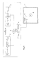
- FIG. 1 shows an IR camera according to an embodiment.
- FIG. 2 shows an exemplary operation of an IR camera according to an embodiment.
- FIG. 3 shows another exemplary operation of an IR camera according to an embodiment.
- FIG. 4 shows further exemplary operation of an IR camera according to an embodiment.
- FIG. 5 is a flowchart illustrating a method according to an exemplary embodiment.
- FIG. 6 is a flowchart illustrating a method according to an exemplary embodiment.
- FIG. 7 is a flowchart illustrating a method according to an exemplary embodiment.
- FIG. 1 shows an IR camera 1 according to an exemplary embodiment.
- the IR camera 1 may capture thermal radiation of an imaged view 2 in response to receiving inputs from a user of the IR camera 1 , and present the thermal radiation in the form of thermal images to a user of the IR camera 1 via an IR camera display 11 .
- the IR camera 1 may comprise a thermal radiation capturing arrangement for capturing thermal radiation comprising at least one lens arrangement 4 , a detector element 5 and a signal conditioning unit 6 .
- the incoming radiation to the IR camera 1 is focused by at least one lens arrangement 4 onto the detector element 5 .
- the detector element 5 may typically be a matrix of detector elements, each of which may detect radiation from a corresponding area, for example, a wall, water pipes, electrical connectors, etc., that is being imaged.
- the detector element 5 may, for example, be a focal plane array (FPA).
- FPA focal plane array
- captured thermal radiation data T x,y may be fed to a signal comprising signal values to a signal conditioning unit 6 .
- the signal conditioning unit 6 may perform conventional signal conditioning, such as, for example, corrections for the inherent offset, gain drift, etc, and convert the signal values into thermal radiation data T x,y comprising temperature values.
- the signal conditioning unit 6 is arranged to output a thermal radiation signal comprising the thermal radiation data T x,y to a processing unit 7 .
- the processing unit 7 is arranged to receive the thermal radiation signal comprising the thermal radiation data T x,y from the signal conditioning unit 6 .
- the processing unit 7 is also arranged to control an IR camera display 11 , for example, a viewfinder, a digital display and/or touch screen provided on the IR camera housing.
- the processing unit 7 is further arranged to process the thermal radiation data T x,y in order for the thermal radiation data T x,y to be displayed by the IR camera display 11 as thermal images.
- the processing unit 7 may output a thermal image signal to the IR camera display 11 .
- the thermal image signal to the IR camera display 11 may also comprise additional information other than the thermal images to be displayed by the IR camera display 11 .
- the thermal, radiation data recorded by the IR camera 1 can thus controlled to be displayed in the IR camera display 11 as thermal images, with or without the additional information, and be presented to a user of the IR camera 1 .
- the operation of the processing unit 7 in the IR camera 1 is described in more detail in the exemplary embodiments presented below with reference to FIGS. 2-5 .
- the signal conditioning unit 6 and the processing unit 7 may be provided as one physical unit, or alternatively as a plurality of logically interconnected units.
- the signal conditioning unit 6 and the processing unit 7 may also comprise processing means or logic for performing the functionality of the IR camera 1 . This functionality may be implemented partly by means of a software or computer program.
- the signal conditioning unit 6 and the processing unit 7 may also comprise storage means or a memory unit for storing such a computer program and processing means or a processing unit, such as a microprocessor, for executing the computer program.
- the storage means may be a readable storage medium, but also a memory storage unit 10 separated from, but connected to the signal conditioning unit 6 and the processing unit 7 .
- the signal conditioning unit 6 or the processing unit 7 performs a certain function or operation it is to be understood that the signal conditioning unit 6 and/or the processing unit 7 may use the processing means or logic to execute a certain part of the program which is stored in the storage means.
- the processing unit 7 may also be connected to and/or arranged to communicate with a distance determining unit 8 arranged to determine the distance between an object 3 in the imaged view 2 and the IR camera 1 and output the measured distance to the processing unit 7 .
- the distance determining unit 8 may, for example, be the at least one lens arrangement 4 using focusing operations to determine the distance to an object 3 , a laser distance measurement unit measuring the distance to the object 3 using laser, or any other type of distance measuring unit.
- the processing unit 7 may also be connected to and/or arranged to communicate with at least one input control unit(s) 12 arranged to receive manual inputs from a user of the IR camera 1 and output the manual inputs to the processing unit 7 .
- the at least one input control unit(s) 12 may, for example, be buttons and/or joysticks, or be incorporated in the IR camera display 11 as a touch screen functionality.
- the processing unit 7 may also be connected to and/or arranged to communicate with at least one temperature measurement unit(s) 13 arranged to measure the surrounding air temperature and/or a surface temperature and output the measured air temperature values and/or surface temperature values to the processing unit 7 .
- the at least one temperature measurement unit(s) 13 may be integrated into the IR camera 1 (as shown in FIG. 1 ), or be comprised in a separate unit arranged to be connected to or communicate with the IR camera 1 from the outside of the IR camera 1 (e.g. by wire or wirelessly).
- the at least one temperature measurement unit(s) 13 may comprise an air temperature measurement unit and/or a surface contact measuring unit.
- the processing unit 7 may also be connected to and/or arranged to communicate with a wind speed measurement unit 15 arranged to measure the wind speed of the air surrounding the object 3 and output measured wind speed values to the processing unit 7 .
- the at least one air temperature measurement unit(s) 13 may be integrated into the IR camera 1 (as shown in FIG. 1 ), or be comprised in a separate unit arranged to be connected to or communicate with the IR camera 1 from the outside of the IR camera 1 (e.g. by wire or wirelessly).
- the operation and use of the distance determining unit 8 , the at least one input control unit(s) 12 , the at least one air temperature measurement unit(s) 13 , and the wind speed measurement unit 15 are described in more detail in the exemplary embodiments presented below with reference to FIGS. 2-5 .
- FIG. 2 shows an exemplary operation of the processing unit 7 in an embodiment of an IR camera 1 .
- the processing unit 7 in the IR camera is arranged to perform calculations of power density values PD x,y in the imaged view 2 indicative of an amount of energy dissipated in the imaged view 2 for temperature values of the thermal radiation data T x,y by using at least one determined temperature reference value.
- the IR camera 1 is able to calculate and/or display the power density distribution of an imaged view 2 .
- the IR camera 1 may increase usability to a user of the IR camera 1 when the user of the IR camera 1 is attempting to analyze the imaged view 2 captured by the IR camera 1 . This further may allow a user of the IR camera 1 to achieve an estimate of the energy properties of the imaged view 2 in a simple and easy manner without having to perform any manual calculations of the same.
- the processing unit 7 may be arranged to perform the calculation of the power dissipated in the imaged view 2 (referred to herein as an output power values or output power density values, PD x,y ) based on calculated values of the energy exchanged through radiation from a surface(s) in the imaged view 2 to its surrounding environment (referred to herein as the radiated power values, PD x,y rad ). This is illustrated by the logical block 21 in FIG. 2 .
- the processing unit 7 may further be arranged to perform the calculation of the output power value PD x,y based on the calculated value of the heat transfer due to natural convection from a surface(s) in the imaged view 2 to its surrounding environment (referred to herein as the convection power value, PD x,y conv ).
- the convection power value PD x,y conv
- the output power value PD x,y may also be calculated by the processing unit 7 as either the radiated power value PD x,y rad or the convection power value, PD x,y conv .
- the processing unit 7 in the IR camera 1 has calculated the output power values PD x,y in accordance with the above, the processing unit 7 may be arranged to control the IR camera display 11 to display the calculated output power values PD x,y to a user of the IR camera 1 in place of the thermal images, e.g. as shown in FIG. 2 .
- the thermal image pixels in a first display area 24 show a first subset of the thermal image radiation data T x,y for which the output power values PD x,y are the same, for example, 28 W/m 2 .
- the IR camera display 11 may be arranged to present the output power values PD x,y in IR camera display 11 in the similar manner as for thermal image, such as, for example, using a colour palette to indicate different output power values PD x,y , and a indication scale 27 , etc. Furthermore, in the IR camera display 11 shown in FIG.
- the thermal image pixels in a second display area 25 show a second subset of the thermal image radiation data T x,y for which the output power values PD x,y are the same, for example, 37 W/m 2
- the thermal image pixels in a third display area 26 show a third subset of the thermal image radiation data T x,y for which the output power values PD x,y are the same, for example, 46 W/m 2 .
- the processing unit 7 may be arranged to control the IR camera display 11 to also display information indicating to the user of the IR camera 1 that this is the case.
- the processing unit 7 may also be arranged to store the output power values PD x,y in the memory storage unit 10 , for example, in order to perform post-processing of the output power values PD x,y .
- the processing unit 7 in the IR camera 1 calculates the output power values PD x,y the parameters T rad,env , T conv,env , h and ⁇ comprised in Eq. 1-4 have to be determined by the processing unit 7 .
- the temperature reference values T rad,env and T conv,env representing the temperature of the surrounding environment of the imaged view 2 may be determined by the processing unit 7 by receiving information from the input control unit(s) 12 comprising at least one temperature value to be used as both or one of the temperature reference values T rad,env and T conv,env .
- the user of the IR camera 1 may thus be arranged to manually enter a temperature value to the processing unit 7 , which may be used by the processing unit 7 as both or one of the temperature reference values T rad,env and T conv,env .
- the processing unit 7 may be arranged to determine either or both of the temperature reference values T rad,env and T conv,env by receiving a temperature measurement value(s) from the temperature measuring unit(s) 13 .
- This alternative will also allow the processing unit 7 of the IR camera 1 to automatically determine either or both of the temperature reference values T rad,env and T conv,env to be used in the calculation of the output power value PD x,y .
- Any one of the alternatives described above may be used by the processing unit 7 in the IR camera 1 in order to determine the temperature reference value T rad,env and/or the temperature reference value T conv.env .
- the IR camera 1 may use a surface temperature measurement unit arranged to detect a surface temperature for determining the temperature reference value T rad,env and a air temperature measurement unit arranged to detect an air temperature for determining the temperature reference value T conv,env .
- the heat transfer coefficient h indicates the amount of natural convection occurring at a surface(s) in the imaged view 2 , and may be determined by the processing unit 7 by receiving information from the input control unit(s) 12 comprising a heat transfer coefficient value.
- the heat transfer coefficient value may be inputted manually by a user of the IR camera 1 .
- the heat transfer coefficient value may be based on information indicating the wind speed of the air surrounding the imaged view 2 received from the wind speed measuring unit 15 .
- the processing unit 7 may determine a corresponding heat transfer coefficient value to be used by the processing unit when calculating the output power values PD x,y .
- the heat transfer coefficient value may also be set to a suitable default value, such as, for example, 1 ⁇ h ⁇ 10 for indoor environments, and 1 ⁇ h ⁇ 100 for outdoor environments.
- the emissivity ⁇ of surface(s) in the imaged view 2 may be determined by the processing unit 7 by receiving information from the input control unit(s) 12 comprising a value of the emissivity of the surface(s).
- the value of the emissivity ⁇ of the surface(s) may be inputted manually by a user of the IR camera 1 .
- FIG. 3 shows another exemplary operation of the processing unit 7 in an embodiment of an IR camera 1 .
- the processing unit 7 in the IR camera 1 is arranged to perform calculations of the power which is outputted from an object 3 in the imaged view 2 .
- the power outputted from the object 3 may also be referred to as the total heat loss of the object 3 as viewed by the IR camera 1 .
- the IR camera 1 may increase usability to a user of the IR camera 1 when the user of the IR camera 1 is attempting to analyze the object 3 by viewing the thermal images of the IR camera 1 . This may allow a user of the IR camera 1 to achieve an estimate of the energy properties of the imaged object 3 in a simple and easy manner without having to perform any manual calculations of the same.
- the processing unit 7 may be arranged to perform the calculation of the power outputted from an object 3 in the imaged view 2 (referred to herein as an object output power value, P TOT obj ) based on a calculated value of the energy exchanged by the object 3 through radiation from its surface to its surrounding environment (referred to herein as the radiated power value, P rad obj ). This is illustrated by the logical block 31 in FIG. 3 .
- the processing unit 7 may further be arranged to perform the calculation of the object output power value P TOT obj based on the calculated value of the heat transfer due to natural convection from the object 3 to its surrounding environment (referred to herein as the convection power value, P conv obj .
- the object output power value P TOT obj is useful since it sums the power outputted from the object 3 through both radiation and convection and may thus achieve a more accurate estimation of a value of the outputted power from the object 3 . It should be noted that the object output power value P TOT obj may also be calculated by the processing unit 7 as either the radiated power value P rad obj or the convection power value, P conv obj .
- the radiated power value P rad obj from the object 3 in the imaged view 2 may be calculated in the logical block 31 by the processing unit 7 according to the following equation, Eq. 6:
- P rad obj ⁇ ⁇ A ⁇ ⁇ ⁇ ⁇ x , y ⁇ ⁇ ( T x , y obj ) 4 - T rad , env 4 ( Eq . ⁇ 6 ) wherein ⁇ is the emissivity of the surface of the object 3 ,
- the convection power value P conv obj from the object 3 in the imaged view 2 may be calculated in the logical block 32 by the processing unit 7 according to the following equation, Eq. 7:
- the object output power value P TOT obj may be calculated by the processing unit 7 according to the following equation, Eq. 8:
- the processing unit 7 in the IR camera 1 may be arranged to control the IR camera display 11 to display the object output power value P TOT obj to a user of the IR camera 1 together with the thermal images, e.g. as shown in FIG. 1 .
- the processing unit 7 may be arranged to control the IR camera display 11 to also display information indicating to the user of the IR camera 1 that this is the case.
- the object output power value P TOT obj indicative of the amount of energy outputted from the object 3 in the imaged view 2 can be said to be based upon output power values PD x,y belonging to the determined thermal image object area 35 in the thermal radiation data T x,y , which may referred to as object output power density values PD x,y obj .
- the object output power density values PD x,y obj can be said to comprise power density values in W/m 2 for temperature values in the thermal radiation data T x,y , which when summed over a defined area, such as, the thermal image object area 35 of the object 3 , results in an object output power value P TOT obj in W.
- the parameters T x,y obj , or PD x,y obj , and A comprised in Eq. 5-9 have to be determined by the processing unit 7 .
- the parameters T rad,env , T conv,env , h and ⁇ may be determined by the processing unit 7 in the same manner as described in the previous embodiment described in relation to FIG. 2 .
- the first subset T x,y obj of the thermal radiation data T x,y corresponds to a thermal image object area 35 in the thermal images displayed on the display unit 11 .
- the thermal image object area 35 represents the object 3 in the imaged view 2 for which an output power value P TOT obj is to be determined.
- the thermal image object area 35 may be determined by the processing unit 7 by receiving information from the input control unit(s) 12 indicating a particular area in the thermal images displayed on the display unit 11 as the thermal image object area 35 . By receiving the information indicating a particular area as the thermal image object area 35 , the processing unit 7 may identify the first subset T x,y obj of the thermal radiation data T x,y corresponding to the indicated thermal image object area 35 .
- the user of the IR camera 1 may, using the input control unit(s) 12 , place a digital marker or indicator around the particular area in the thermal images to be indicated as the thermal image object area 35 in the thermal images.
- the thermal image object area 35 and the corresponding first subset T x,y obj of the thermal radiation data T x,y may be determined by the processing unit 7 by using a temperature threshold value.
- the temperature threshold value will directly indicate a first subset T x,y obj of the thermal radiation data T x,y as the thermal image object area 35 .
- the temperature threshold value may be a user-settable threshold value or a default threshold value.
- the user of the IR camera 1 may set the temperature threshold value to be used in determining the thermal image object area 35 and the corresponding first subset T x,y obj of the thermal radiation data T x,y , by using the input control unit(s) 12 .
- the same procedures may be used in order to determine the object output power density values PD x,y obj from which the object output power value P TOT obj may be calculated as well.
- the temperature reference values T rad,env and T conv,env representing the temperature of the surrounding environment of the object 3 in the imaged view 2 may be determined by the processing unit 7 in the same mariner as described in the previous embodiment described in relation to FIG. 2 .
- the processing unit 7 may here be arranged to determine a second subset T x,y ref of the thermal radiation data T x,y as a thermal image reference area 36 (shown in FIG. 3 ).
- the thermal image reference area 36 may be determined by the processing unit 7 as the part of the thermal radiation data T x,y that is not a part of the determined thermal image object area 35 in the thermal radiation data T x,y , i.e.
- the processing unit 7 may determine either or both of the temperature reference values T rad,env and T conv,env as the representative temperature value obtained for the thermal image reference area 36 in the thermal radiation data T x,y .
- the representative temperature value of the thermal image reference area 36 may, for example, be calculated by the processing unit 7 as median or mean value of the thermal radiation data T x,y in the determined thermal image reference area 36 . This alternative allows the processing unit 7 of the IR camera 1 to automatically determine either or both of the temperature reference values T rad,env and T conv,env to be used in the calculation of the object output power value P TOT obj .
- the surface area parameter A represents the actual surface area of the object 3 facing towards and being perceived by 2D-camera view of the IR camera 1 in the imaged view 2 .
- the surface area parameter A may be determined by the processing unit 7 by receiving information from the input control unit(s) 12 comprising a value of the actual physical surface area of the object 3 .
- the user of the IR camera 1 may thus be arranged to manually enter an area value to the processing unit 7 corresponding to the surface of the object 3 , which may be used by the processing unit 7 as a value of the surface area parameter A.
- the value of the surface area parameter A may also be set to a suitable default value.
- the processing unit 7 may be arranged to receive information from the distance determining unit 8 comprised in the IR camera 1 , wherein the information comprises a distance d between the actual physical object 3 in the imaged view 2 and the IR camera 1 . Further, the processing unit 7 may be arranged to determine an object field-of-view o fov 14 of the determined thermal image object area 35 in the thermal radiation data T x,y .
- An object field-of-view o fov 14 of a determined thermal image object area 35 in the thermal radiation data T x,y may be determined by the processing unit 7 by, for example, from the first subset T x,y obj of the thermal radiation data T x,y determined as the thermal image object area 35 , determine how much of the total field-of-view 2 of the IR camera 1 , i.e.
- the processing unit 7 may calculate an estimate of the actual physical surface area of the object 3 in the imaged view 2 facing towards and being perceived by 2D-camera view of the IR camera 1 , i.e.
- the surface area parameter A based upon the received distance d to the object 3 and the determined object field-of-view o fov 14 .
- this may be performed by the processing unit 7 by using the area a x,y pix for each thermal image pixel in the object field-of-view o fov 14 of the determined thermal image object area 35 according to the following equation, Eq. 10-11:
- a x , y pix ( 2 ⁇ d ⁇ tan ⁇ ( o fov pix / 2 ) ) 2 ( Eq . ⁇ 10 )
- A ⁇ x , y ⁇ ⁇ a x , y pix ( Eq . ⁇ 11 )
- the field-of-view for each pixel o fov pix in the object field-of-view o fov 14 of the determined thermal image object area 35 may, for example, by dividing the total field-of-view of the IR camera 1 by the resolution of the detector element 5 in the IR camera 1 .
- the processing unit 7 may be arranged to receive information from the input control unit(s) 12 which comprises a form indicator ⁇ ind .
- the form indicator ⁇ ind may be indicative of the shape or form of the actual physical object 3 in the imaged view 2 .
- the form indicator ⁇ ind may be used to describe and represent the actual shape, form and/or orientation of the surface of the object 3 facing and being perceived by 2D-camera view of the IR camera 1 .
- the form indicator ⁇ ind may be used to describe and represent the 3D-shape or form of the object 3 in the imaged view 2 .
- the form indicator ⁇ ind or a corresponding value stored for the particular form indicator in the memory storage unit 10 or in the processing unit 7 , may be used by the processing unit 7 when calculating the object output power value P TOT obj . For example, this may be performed by the processing unit 7 by modifying Eq.11 according to the following equation, Eq. 12:
- the form indicator ⁇ ind may be used to adapt the surface area parameter according to the actual 3D shape and form of the object 3 in the imaged view 2 .
- the form indicator ⁇ ind may be manually inputted by the user of the IR camera 1 through the input control unit(s) 12 .
- the user of the IR camera 1 may also be presented in the display unit 11 with a range of alternative object views from which the user of the IR camera 1 may select the most suitable alternative using the input control unit(s) 12 , whereby the form indicator ⁇ ind associated with the selected object view may be used by the processing unit 7 when calculating the object output power value P TOT obj .
- the alternative object views may, for example, be images describing different geometric fowls and/or the angle from which the object 3 having a particular geometric form is viewed by the IR camera 1 .
- the processing unit 7 may be arranged to estimate the shape or form of the actual physical object 3 in the imaged view 2 using this distance map.
- the distance map comprise separate distance values for different subsets of the thermal radiation data T x,y , for example, one distance value for each captured temperature value by the detector element 5 .
- the processing unit 7 may determine the distances to each temperature value in the first subset T x,y obj of the thermal radiation data T x,y corresponding to the thermal image object area 35 .
- the processing unit 7 is thus able to achieve a 3D-representation of the object 3 in the imaged view 2 and may use the 3D-representation of the object 3 when calculating the object output power value P TOT obj .
- This may, for example, be performed by the processing unit 7 by determining a suitable form indicator ⁇ ind to be used in dependence of the 3D-representation of the object 3 , or by comprising an area estimation algorithm which may estimate the surface area of the object 3 using the 3D-representation of the object 3 . This may be performed for the surface of the object 3 facing and being perceived by 2D-camera view of the IR camera 1 .
- the processing unit 7 may be arranged to incorporate the 3D-representation of the object 3 in Eq. 8 by having the area a x,y pix for each thermal image pixel in the object field-of-view o fov 14 of the determined thermal image object area 35 included in calculation of the object output power value P TOT obj according to the following equation, Eq. 13:
- P TOT obj ⁇ ⁇ ⁇ ⁇ ⁇ x , y ⁇ ⁇ a x , y ⁇ ( ( T x , y obj ) 4 - T rad , env 4 ) + h ⁇ ⁇ x , y ⁇ ⁇ a x , y ⁇ ( T x , y obj - T conv , env ) ( Eq . ⁇ 13 ) wherein a x,y pix is dependent upon its corresponding value d in the distance map.
- the processing unit 7 may be arranged to combine the use of a form indicator ⁇ ind according to the previous alternative (for example, to determine an object output power value P TOT obj for the entire object 3 , that is, not only for the surface of the object 3 facing and being perceived by 2D-camera view of the IR camera 1 ) with a form indicator f ⁇ ind , or 3D representation, according to the latter alternative (for example, to determine the surface of the object 3 facing and being perceived by 2D-camera view of the IR camera 1 ) when calculating the object output power value P TOT obj .
- FIG. 4 shows an exemplary operation of the processing unit 7 in another embodiment of an IR camera 1 .
- the processing unit 7 according to this embodiment is identical to the processing unit 7 according the previous embodiment, except that the processing unit 7 further comprises the functionality of the logical block 41 .
- the processing unit 7 in the IR camera 1 may be arranged to receive information comprising the current energy price information c meas and/or a time span information t meas from the input control unit(s) 12 .
- the current energy price information c meas and/or a time span information t meas may be inputted manually by a user of the IR camera 1 .
- the current energy price info nation c meas is a value that relates the object output power value P TOT obj accumulated over time to an actual energy cost for having the object 3 emitting that amount of energy during that time.
- the time span information t meas may be obtained by having the processing unit 7 start a time span measurement when a user of the IR camera 1 indicates to the processing unit 7 using the input control unit(s) 12 that the object output power calculation according to the above should begin and stop the time span measurement when the user of the IR camera 1 indicates to the processing unit 7 using the input control unit(s) 12 that the object output power calculation according to the above should stop.
- the time span information t meas may also be provided to the processing unit 7 after the object output power calculation by the processing unit 7 has been performed over a particular time period, whereby the time span information t meas may indicate a subset of that particular time period.
- the time span information t meas may be used by the processing unit 7 for calculating a total energy output value E TOT obj for the object 3 in the imaged view 2 .
- the total energy cost value C may also be calculated using Eq.15.
- the processing unit 7 may then control the IR camera display 11 to display the total energy cost value (as shown in FIG. 4 ) and/or the total energy output value E TOT obj to a user of the IR camera 1 together with the thermal images.
- the displayed total energy cost value (as shown in FIG. 4 ) and/or total energy output value E TOT obj may also be displayed in the display unit 11 a running value that is continuously updated for an time span that has begun, but not been stopped yet.
- the displayed total energy cost value (as shown in FIG. 4 ) and/or total energy output value E TOT obj may also be displayed in the display unit 11 in a separate indicator window 42 . This enables a simple and clear identification of the total energy cost value (as shown in FIG. 4 ) and/or total energy output value E TOT obj by the user of the IR camera 1 .
- FIG. 5 is a flowchart illustrating a method to be used in a processing unit 7 in an exemplary embodiment of an IR camera 1 .
- the processing unit 7 may determine at least one temperature reference value.
- the at least one temperature reference value may represent the temperature of the surrounding environment of an imaged view in the IR camera.
- the processing unit 7 may calculate at least one output power value using the temperature value of the thermal radiation data corresponding to a part of the imaged view and the at least one determined temperature reference value.
- the at least one output power value being indicative of an amount of energy dissipated in that part of the imaged view.
- the method described in reference to FIG. 5 may further include the step of controlling an IR camera display to display the at least one calculated output power value to a user of the IR camera in place of the corresponding temperature pixel in the thermal image.
- FIG. 6 is a flowchart illustrating a method to be used in a processing unit 7 , as described with respect to FIG. 3 , in an exemplary embodiment of an IR camera 1 .
- Step S 61 is identical to step S 51 described above.
- the processing unit 7 may determine a thermal image object area in the thermal radiation data. This may be performed by determining a first subset of the thermal radiation data as a thermal image object area representing an object in the imaged view for which an output power value is to be determined.
- the processing unit 7 may calculate an object output power value.
- This may be performed by calculating an object output power value indicative of the amount of energy outputted from the object in the imaged view based upon output power values of the determined thermal image object area in the thermal radiation data.
- the method described in reference to FIG. 6 may further include the step of controlling the IR camera display to display the calculated object output power value to a user of the IR camera together with the thermal images.
- FIG. 7 is a flowchart illustrating a method according to an exemplary embodiment. Step S 71 -S 73 is identical to the steps S 61 -S 63 according to the above.
- the processing unit 7 may receive a time span and current energy price information.
- the processing unit 7 may calculate a total energy cost value. This may be performed by calculating a total energy output value for the object in the imaged view based on the time span information and the calculated object output power value, and by then calculating a total energy cost value based on the current energy price information and the calculated total energy output value.
- the method according to FIG. 5 may further include the step of controlling the IR camera display to display total energy cost value and/or the total energy output value to a user of the IR camera together with the thermal images.
Abstract
An IR camera includes: a thermal radiation capturing arrangement for capturing thermal radiation of an imaged view in response to input control unit(s) receiving user inputs from a user of the IR camera; a processing unit arranged to process the thermal radiation data in order for the thermal radiation data to be displayed by an IR camera display as thermal images; and an IR camera display arranged to display thermal images to a user of the IR camera. The processing unit is further arranged to determine at least one temperature reference value representing the temperature of the surrounding environment of the imaged view; and calculate at least one output power value indicative of an amount of energy dissipated in a part of the imaged view by using the temperature value of the thermal radiation data corresponding to said part of the imaged view and the at least one determined temperature reference value.
Description
This patent application is a continuation of U.S. patent application Ser. No. 13/774,870 filed Feb. 22, 2013, which is a continuation of U.S. patent application Ser. No. 12/569,847 filed Sep. 29, 2009, all of which are incorporated herein by reference in their entirety.
The present technology relates in general to IR cameras and methods for use in a processing unit of IR cameras, in particular to IR camera and methods for capturing IR radiation data of an imaged view.
Infrared (IR) thermal cameras can be used in a number of different situations, for example, when inspecting or surveying complex electrical systems such as transformers, switchgears etc., or water carrying systems such as heat exchangers, radiators etc. IR cameras are used for capturing and storing thermal radiation data. This thermal radiation data may then be displayed and viewed as thermal images and analyzed in order to, for example, find faulty electrical wirings or couplings, leaking water pipes, etc.
However, various procedures and methods are being used in order to properly analyse the thermal radiation data and/or the thermal images of the IR camera, and these are not necessarily particularly intuitive and easily understandable by a user of the IR camera. The analysis of the thermal radiation data and/or the thermal images of an IR camera may also be a time-consuming task and may thus preclude a user of an IR camera from making decisions, predictions, and/or recommendations to clients while being on site and performing the IR imaging.
Accordingly, there is a need to provide an IR camera with increased usability when analysing thermal images.
In order to solve the above-mentioned and other problems, in an exemplary embodiment, an IR camera comprises: a thermal radiation capturing arrangement for capturing thermal radiation of an imaged view in response to an input control unit(s) receiving inputs from a user of the IR camera; a processing unit arranged to process the thermal radiation data in order for the thermal radiation data to be displayed by an IR camera display as thermal images; and an IR camera display arranged to display thermal images to a user of the IR camera. The processing unit of the IR camera may be further arranged to: determine at least one temperature reference value representing the temperature of the surrounding environment of the imaged view; and calculate at least one output power value indicative of an amount of energy dissipated in a part of the imaged view by using the temperature value of the thermal radiation data corresponding to said part of the imaged view and the at least one determined temperature reference value.
The exemplary embodiment may increase usability to a user of an IR camera when analysing the thermal images of the IR camera by enabling a calculation of the output power dissipated in an imaged view. This also allows a user of the IR camera to achieve an estimate of the energy properties of an imaged view in a simple and easy manner.
The processing unit of the IR camera may also be arranged to control the IR camera display to display the at least one calculated output power value to a user of the IR camera in place of the corresponding temperature pixel in the thermal image. This enables the user of the IR camera to monitor the outputted power density of the energy radiating from an imaged view directly in the IR camera display as the object is being imaged by the IR camera.
The processing unit of the IR camera may also be arranged to determine a first subset of the thermal radiation data as a thermal image object area representing an object in the imaged view for which an output power value is to be determined; and calculate an object output power value indicative of the amount of energy outputted from the object in the imaged view based upon output power values of the determined thermal image object area in the thermal radiation data. This may provide increased usability to a user of an IR camera when analysing the thermal images of the IR camera by enabling a calculation of the output power radiating from an object in an imaged view. This also allows a user of the IR camera to achieve an estimate of the energy properties of an imaged object in a simple and easy manner
The processing unit of the IR camera may also be arranged to control the IR camera display to display the calculated object output power value to a user of the IR camera together with the thermal images. This enables the user of the IR camera to monitor the output power radiating from an object directly in the IR camera display as the object is being imaged by the IR camera. The processing unit of the IR camera may also be arranged to receive information comprising current energy price information and time span information. This may be performed by the user of the IR camera using the input control devices. By being further arranged to calculate the energy outputted by the object in the imaged view based on this time span information and the object output power value, an estimated cost of the total energy consumption may be based on the received current energy price information and the outputted energy. This cost estimate may then be displayed by the IR camera display to the user of the IR camera together with the thermal images, such that a fast and efficient energy cost evaluation for the object may be performed immediately on site.
The processing unit of the IR camera may further be arranged to determine the thermal image object area in the thermal radiation data by receiving information from the input control unit(s) indicating a subset of the thermal radiation data as the thermal image object area. This allows a user of the IR camera to manually indicate an area in the displayed IR thermal images of the IR camera display representing the object for which the user of the IR camera desires the output power to be determined; the indicated area will correlate to a particular subset of the thermal radiation data. While this alleviates the need for any thermal image segmentation to be performed automatically by the IR camera, an area representing the object for which the user of the IR camera desires the output power to be determined may also be established using a temperature threshold value. This enables the IR camera to automatically identify a subset of the thermal radiation data as the thermal image object area.
Furthermore, the processing unit of the IR camera may be arranged to receive information from the input control unit(s) comprising a value of the actual physical surface area of the object in the imaged view facing towards the IR camera, whereby this area value may be used when calculating the object output power value. This alleviates the need for an object area estimation to be performed automatically by the IR camera. The processing unit of the IR camera may also be arranged to receive information from a distance determining unit comprised in the IR camera which comprises the distance between the actual physical object captured in the imaged view and the IR camera, determine an object field-of-view of the determined thermal image object area in the thermal radiation data, estimate the actual physical surface area of the object in the imaged view facing towards the IR camera based upon the received distance and the determined object field-of-view, and use this estimation when calculating the object output power value. This enables the IR camera to automatically estimate the actual physical surface area of the object in the imaged view facing towards the IR camera.
Additionally, the processing unit of the IR camera may be arranged to receive information from the input control unit(s) comprising a form indicator which is indicative of the shape or form of the actual physical object in the imaged view, and use this form indicator or a corresponding value when calculating the object output power value. This enables the IR camera to use the object output power value calculated using the estimate of the actual physical surface area of the object facing towards the IR camera for estimating a total object output power value for the entire physical object by taking actual physical surface areas of the object not visible in the imaged view into consideration in the power calculation. The processing unit of the IR camera may also be arranged to, when the distance comprised in the information from the distance determining unit is a distance map comprising separate distance values for different subsets of the thermal radiation data, estimate the shape or form of the actual physical object in the imaged view using the distance map, and use this estimate when calculating the object output power value. This enables the IR camera to more accurately estimate actual physical surface areas of the object in the imaged view, and consequently estimating an improved total object output power value for the entire physical object viewed.
The processing unit of the IR camera may furthermore be arranged to determine the at least one temperature reference value by receiving information from the input control unit(s) comprising a temperature value(s) to be used as the at least one temperature reference value. This allows a user of the IR camera to input the at least one temperature reference value into the IR camera manually. The processing unit of the IR camera may also be arranged to determine a thermal image reference area in the thermal radiation data that is not part of the determined thermal image object area in the thermal radiation data, calculate a representative temperature value for the thermal image reference area in the thermal radiation data, and using the representative temperature value for the thermal image reference area in the thermal radiation data as the at least one temperature reference value when determining the at least one temperature reference value. Alternatively, the processing unit of the IR camera may be arranged to determine the at least one temperature reference value by receiving temperature value(s) from at least one temperature measurement unit(s) comprised in the IR camera. The two latter features allows the IR camera to automatically determine the at least one temperature reference value to be used in the power calculations.
According to another exemplary embodiment, a method for use in a processing unit of an IR camera capturing thermal radiation data of an imaged view is provided. The method may comprise: determining a subset of the thermal radiation data as a thermal image object area representing an object in the imaged view for which an output power value is to be determined; determining at least one temperature reference value representing the temperature of the surrounding environment of the object in the imaged view; and calculating an object output power value indicative of the amount of energy dissipated from the object in the imaged view based upon the determined thermal image object area in the thermal radiation data, and the at least one determined temperature reference value.
The method may further comprise: controlling the IR camera display to display the calculated object output power value to a user of the IR camera together with the thermal images. Alternatively, the method may also comprise: receiving information comprising current energy price information and time span information, calculating a total energy output value for the object in the imaged view based on the time span information and the calculated object output power value, calculating a total energy cost value based on the current energy price information and the total energy output value, and controlling the IR camera display to display total energy cost value to a user of the IR camera together with the thermal images.
According to yet another exemplary embodiment, a computer program product for use in an IR camera is provided, which comprises computer executable instructions that, when run in a processing unit in the IR camera cause the processing unit in the IR camera to: determine a subset of the thermal radiation data captured by the IR camera as a thermal image object area representing an object in the imaged view for which an output power value is to be determined; determine at least one temperature reference value representing the temperature of the surrounding environment of the object in the imaged view; and calculate an object output power value indicative of the amount of energy outputted from the object in the imaged view based upon the determined thermal image object area in the thermal radiation data, and the at least one determined temperature reference value.
Further embodiments of the IR camera, the method, and the computer program product are set forth in the dependent claims and the rest of the specification.
From the detector element 5, captured thermal radiation data Tx,y may be fed to a signal comprising signal values to a signal conditioning unit 6. The signal conditioning unit 6 may perform conventional signal conditioning, such as, for example, corrections for the inherent offset, gain drift, etc, and convert the signal values into thermal radiation data Tx,y comprising temperature values. The signal conditioning unit 6 is arranged to output a thermal radiation signal comprising the thermal radiation data Tx,y to a processing unit 7.
The processing unit 7 is arranged to receive the thermal radiation signal comprising the thermal radiation data Tx,y from the signal conditioning unit 6. The processing unit 7 is also arranged to control an IR camera display 11, for example, a viewfinder, a digital display and/or touch screen provided on the IR camera housing. The processing unit 7 is further arranged to process the thermal radiation data Tx,y in order for the thermal radiation data Tx,y to be displayed by the IR camera display 11 as thermal images. The processing unit 7 may output a thermal image signal to the IR camera display 11. The thermal image signal to the IR camera display 11 may also comprise additional information other than the thermal images to be displayed by the IR camera display 11. The thermal, radiation data recorded by the IR camera 1 can thus controlled to be displayed in the IR camera display 11 as thermal images, with or without the additional information, and be presented to a user of the IR camera 1. The operation of the processing unit 7 in the IR camera 1 is described in more detail in the exemplary embodiments presented below with reference to FIGS. 2-5 .
It should be noted that the signal conditioning unit 6 and the processing unit 7 may be provided as one physical unit, or alternatively as a plurality of logically interconnected units. The signal conditioning unit 6 and the processing unit 7 may also comprise processing means or logic for performing the functionality of the IR camera 1. This functionality may be implemented partly by means of a software or computer program. The signal conditioning unit 6 and the processing unit 7 may also comprise storage means or a memory unit for storing such a computer program and processing means or a processing unit, such as a microprocessor, for executing the computer program. The storage means may be a readable storage medium, but also a memory storage unit 10 separated from, but connected to the signal conditioning unit 6 and the processing unit 7. When, in the following, it is described that the IR camera 1, the signal conditioning unit 6 or the processing unit 7 performs a certain function or operation it is to be understood that the signal conditioning unit 6 and/or the processing unit 7 may use the processing means or logic to execute a certain part of the program which is stored in the storage means.
The processing unit 7 may also be connected to and/or arranged to communicate with a distance determining unit 8 arranged to determine the distance between an object 3 in the imaged view 2 and the IR camera 1 and output the measured distance to the processing unit 7. The distance determining unit 8 may, for example, be the at least one lens arrangement 4 using focusing operations to determine the distance to an object 3, a laser distance measurement unit measuring the distance to the object 3 using laser, or any other type of distance measuring unit. The processing unit 7 may also be connected to and/or arranged to communicate with at least one input control unit(s) 12 arranged to receive manual inputs from a user of the IR camera 1 and output the manual inputs to the processing unit 7. The at least one input control unit(s) 12 may, for example, be buttons and/or joysticks, or be incorporated in the IR camera display 11 as a touch screen functionality. The processing unit 7 may also be connected to and/or arranged to communicate with at least one temperature measurement unit(s) 13 arranged to measure the surrounding air temperature and/or a surface temperature and output the measured air temperature values and/or surface temperature values to the processing unit 7. The at least one temperature measurement unit(s) 13 may be integrated into the IR camera 1 (as shown in FIG. 1 ), or be comprised in a separate unit arranged to be connected to or communicate with the IR camera 1 from the outside of the IR camera 1 (e.g. by wire or wirelessly). The at least one temperature measurement unit(s) 13 may comprise an air temperature measurement unit and/or a surface contact measuring unit. The processing unit 7 may also be connected to and/or arranged to communicate with a wind speed measurement unit 15 arranged to measure the wind speed of the air surrounding the object 3 and output measured wind speed values to the processing unit 7. The at least one air temperature measurement unit(s) 13 may be integrated into the IR camera 1 (as shown in FIG. 1 ), or be comprised in a separate unit arranged to be connected to or communicate with the IR camera 1 from the outside of the IR camera 1 (e.g. by wire or wirelessly). The operation and use of the distance determining unit 8, the at least one input control unit(s) 12, the at least one air temperature measurement unit(s) 13, and the wind speed measurement unit 15 are described in more detail in the exemplary embodiments presented below with reference to FIGS. 2-5 .
By having the processing unit 7 in the IR camera 1 arranged to perform calculations of the power density values PDx,y, the IR camera 1 is able to calculate and/or display the power density distribution of an imaged view 2. Thus, the IR camera 1 may increase usability to a user of the IR camera 1 when the user of the IR camera 1 is attempting to analyze the imaged view 2 captured by the IR camera 1. This further may allow a user of the IR camera 1 to achieve an estimate of the energy properties of the imaged view 2 in a simple and easy manner without having to perform any manual calculations of the same.
The processing unit 7 may be arranged to perform the calculation of the power dissipated in the imaged view 2 (referred to herein as an output power values or output power density values, PDx,y) based on calculated values of the energy exchanged through radiation from a surface(s) in the imaged view 2 to its surrounding environment (referred to herein as the radiated power values, PDx,y rad). This is illustrated by the logical block 21 in FIG. 2 . The processing unit 7 may further be arranged to perform the calculation of the output power value PDx,y based on the calculated value of the heat transfer due to natural convection from a surface(s) in the imaged view 2 to its surrounding environment (referred to herein as the convection power value, PDx,y conv). This is illustrated by the logical block 22 in FIG. 2 . As is illustrated by the logical block 23, the output power values PDx,y may be calculated by the processing unit 7 according to the following equation, Eq.1:
PD x,y =PD x,y rad +PD x,y conv (Eq.1)
PD x,y =PD x,y rad +PD x,y conv (Eq.1)
Although the output power value PDx,y according to Eq. 1 is useful since it sums the power outputted in the imaged view 2 through both radiation and convection and thus may achieve a more accurate estimation of a value indicative of the outputted power in the imaged view, it should be noted that the output power value PDx,y may also be calculated by the processing unit 7 as either the radiated power value PDx,y rad or the convection power value, PDx,y conv.
The radiated power values PDx,y rad in the imaged view 2 may be calculated in the logical block 21 by the processing unit 7 according to the following equation, Eq.2:
PD x,y rad=ε·σ·((T x,y)4 −T rad,env 4) (Eq. 2)
wherein ε is the emissivity of the surface(s) in the imagedview 2,
PD x,y rad=ε·σ·((T x,y)4 −T rad,env 4) (Eq. 2)
wherein ε is the emissivity of the surface(s) in the imaged
-
- σ is the Stefan-Boltzmann constant, 5.67·10−8 W/m2K4,
- Tx,y is the temperature values at positions (x, y) in the thermal radiation data received from the
detector element 5 and thesignal conditioning unit 6, - Trad,env is a temperature reference value representing the temperature of the surrounding environment of the imaged
view 2.
The convection power values PDx,y conv in the imaged view 2 may be calculated in the logical block 22 by the processing unit 7 according to the following equation, Eq.3:
PD x,y conv =h·(T x,y −T conv,env) (Eq. 3)
wherein h is a heat transfer coefficient [W/m2K],
PD x,y conv =h·(T x,y −T conv,env) (Eq. 3)
wherein h is a heat transfer coefficient [W/m2K],
-
- Tconv,env is a temperature reference value representing the temperature of the surrounding environment of the imaged
view 2.
- Tconv,env is a temperature reference value representing the temperature of the surrounding environment of the imaged
Thus, combining Eq.1-3, the output power values PDx,y for each of the temperature values of the thermal radiation data Tx,y may be calculated by the processing unit 7 according to the following equation, Eq. 4:
PD x,y =PD x,y rad +PD x,y conv=ε·σ·((T x,y)4 −T rad,env 4)+h·(T x,y −T conv,env) (Eq. 4)
PD x,y =PD x,y rad +PD x,y conv=ε·σ·((T x,y)4 −T rad,env 4)+h·(T x,y −T conv,env) (Eq. 4)
As the processing unit 7 in the IR camera 1 has calculated the output power values PDx,y in accordance with the above, the processing unit 7 may be arranged to control the IR camera display 11 to display the calculated output power values PDx,y to a user of the IR camera 1 in place of the thermal images, e.g. as shown in FIG. 2 . In the IR camera display 11 shown in FIG. 2 , the thermal image pixels in a first display area 24 show a first subset of the thermal image radiation data Tx,y for which the output power values PDx,y are the same, for example, 28 W/m2. The IR camera display 11 may be arranged to present the output power values PDx,y in IR camera display 11 in the similar manner as for thermal image, such as, for example, using a colour palette to indicate different output power values PDx,y, and a indication scale 27, etc. Furthermore, in the IR camera display 11 shown in FIG. 2 , the thermal image pixels in a second display area 25 show a second subset of the thermal image radiation data Tx,y for which the output power values PDx,y are the same, for example, 37 W/m2, and the thermal image pixels in a third display area 26 show a third subset of the thermal image radiation data Tx,y for which the output power values PDx,y are the same, for example, 46 W/m2. If the output power values PDx,y are calculated by the processing unit 7 as either the radiated power values PDx,y rad or the convection power values PDx,y conv, the processing unit 7 may be arranged to control the IR camera display 11 to also display information indicating to the user of the IR camera 1 that this is the case. The processing unit 7 may also be arranged to store the output power values PDx,y in the memory storage unit 10, for example, in order to perform post-processing of the output power values PDx,y.
However, in order for the processing unit 7 in the IR camera 1 to calculate the output power values PDx,y the parameters Trad,env, Tconv,env, h and ε comprised in Eq. 1-4 have to be determined by the processing unit 7.
The temperature reference values Trad,env and Tconv,env representing the temperature of the surrounding environment of the imaged view 2 may be determined by the processing unit 7 by receiving information from the input control unit(s) 12 comprising at least one temperature value to be used as both or one of the temperature reference values Trad,env and Tconv,env. The user of the IR camera 1 may thus be arranged to manually enter a temperature value to the processing unit 7, which may be used by the processing unit 7 as both or one of the temperature reference values Trad,env and Tconv,env. Alternatively, the processing unit 7 may be arranged to determine either or both of the temperature reference values Trad,env and Tconv,env by receiving a temperature measurement value(s) from the temperature measuring unit(s) 13. This alternative will also allow the processing unit 7 of the IR camera 1 to automatically determine either or both of the temperature reference values Trad,env and Tconv,env to be used in the calculation of the output power value PDx,y. Any one of the alternatives described above may be used by the processing unit 7 in the IR camera 1 in order to determine the temperature reference value Trad,env and/or the temperature reference value Tconv.env. Alternatively, the IR camera 1 may use a surface temperature measurement unit arranged to detect a surface temperature for determining the temperature reference value Trad,env and a air temperature measurement unit arranged to detect an air temperature for determining the temperature reference value Tconv,env.
The heat transfer coefficient h indicates the amount of natural convection occurring at a surface(s) in the imaged view 2, and may be determined by the processing unit 7 by receiving information from the input control unit(s) 12 comprising a heat transfer coefficient value. The heat transfer coefficient value may be inputted manually by a user of the IR camera 1. Alternatively, the heat transfer coefficient value may be based on information indicating the wind speed of the air surrounding the imaged view 2 received from the wind speed measuring unit 15. For a particular wind speed, the processing unit 7 may determine a corresponding heat transfer coefficient value to be used by the processing unit when calculating the output power values PDx,y. This may be performed by the processing unit 7 or the memory storage unit 10 comprising a list associating wind speeds with corresponding heat transfer coefficient values. The heat transfer coefficient value may also be set to a suitable default value, such as, for example, 1≦h≦10 for indoor environments, and 1≦h≦100 for outdoor environments.
The emissivity ε of surface(s) in the imaged view 2 may be determined by the processing unit 7 by receiving information from the input control unit(s) 12 comprising a value of the emissivity of the surface(s). The value of the emissivity ε of the surface(s) may be inputted manually by a user of the IR camera 1. The value of the emissivity ε may also be set to a suitable default value, for example, ε=1.
By having the processing unit 7 in the IR camera 1 arranged to perform calculations of the power which is outputted from an object 3 in the imaged view 2, the IR camera 1 may increase usability to a user of the IR camera 1 when the user of the IR camera 1 is attempting to analyze the object 3 by viewing the thermal images of the IR camera 1. This may allow a user of the IR camera 1 to achieve an estimate of the energy properties of the imaged object 3 in a simple and easy manner without having to perform any manual calculations of the same.
The processing unit 7 may be arranged to perform the calculation of the power outputted from an object 3 in the imaged view 2 (referred to herein as an object output power value, PTOT obj) based on a calculated value of the energy exchanged by the object 3 through radiation from its surface to its surrounding environment (referred to herein as the radiated power value, Prad obj). This is illustrated by the logical block 31 in FIG. 3 . The processing unit 7 may further be arranged to perform the calculation of the object output power value PTOT obj based on the calculated value of the heat transfer due to natural convection from the object 3 to its surrounding environment (referred to herein as the convection power value, Pconv obj. This is illustrated by the logical block 32 in FIG. 3 . As is illustrated by the logical block 33 and as shown in FIG. 3 (e.g., in a display window 34 in IR camera display 11), the object output power value PTOT obj may be calculated by the processing unit 7 according to the following equation, Eq.5:
P TOT obj =P rad obj +P conv obj (Eq.5)
P TOT obj =P rad obj +P conv obj (Eq.5)
Although the object output power value PTOT obj according to Eq. 1 is useful since it sums the power outputted from the object 3 through both radiation and convection and may thus achieve a more accurate estimation of a value of the outputted power from the object 3. It should be noted that the object output power value PTOT obj may also be calculated by the processing unit 7 as either the radiated power value Prad obj or the convection power value, Pconv obj.
The radiated power value Prad obj from the object 3 in the imaged view 2 may be calculated in the logical block 31 by the processing unit 7 according to the following equation, Eq. 6:
wherein ε is the emissivity of the surface of the
-
- A is the surface area of the
object 3 facing towards and being perceived by 2D-camera view of the IR camera 1, - σ is the Stefan-Boltzmann constant, 5.67·10−8 W/m2K4,
- Tx,y obj is a first subset of the thermal radiation data Tx,y received from the
detector element 5 and thesignal conditioning unit 6 which has been determined by theprocessing unit 7 to represent theobject 3 in the imaged view 2 (herein referred to as the thermal image object area 35) for which an object output power value PTOT obj is to be determined, - Trad,env is a temperature reference value representing the temperature of the surrounding environment of the
object 3 in the imagedview 2.
- A is the surface area of the
The convection power value Pconv obj from the object 3 in the imaged view 2 may be calculated in the logical block 32 by the processing unit 7 according to the following equation, Eq. 7:
wherein h is a heat transfer coefficient [W/m2 K],
-
- Tconv,env is a temperature reference value representing the temperature of the surrounding environment of the
object 3 in the imagedview 2.
- Tconv,env is a temperature reference value representing the temperature of the surrounding environment of the
Thus, combining Eq.1-3, the object output power value PTOT obj may be calculated by the processing unit 7 according to the following equation, Eq. 8:
As the processing unit 7 in the IR camera 1 has calculated the object output power value PTOT obj in accordance with the above, the processing unit 7 may be arranged to control the IR camera display 11 to display the object output power value PTOT obj to a user of the IR camera 1 together with the thermal images, e.g. as shown in FIG. 1 . If the object output power value PTOT obj is calculated by the processing unit 7 as either the radiated power value Prad obj or the convection power value, Pconv obj, the processing unit 7 may be arranged to control the IR camera display 11 to also display information indicating to the user of the IR camera 1 that this is the case.
As can be seen from Eq. 1-4 in the previous embodiment described in reference to FIG. 2 and Eq. 9 below, the object output power value PTOT obj indicative of the amount of energy outputted from the object 3 in the imaged view 2 can be said to be based upon output power values PDx,y belonging to the determined thermal image object area 35 in the thermal radiation data Tx,y, which may referred to as object output power density values PDx,y obj. The object output power density values PDx,y obj can be said to comprise power density values in W/m2 for temperature values in the thermal radiation data Tx,y, which when summed over a defined area, such as, the thermal image object area 35 of the object 3, results in an object output power value PTOT obj in W.
However, in order for the processing unit 7 in the IR camera 1 to calculate the object output power value PTOT obj the parameters Tx,y obj, or PDx,y obj, and A comprised in Eq. 5-9 have to be determined by the processing unit 7. The parameters Trad,env, Tconv,env, h and ε may be determined by the processing unit 7 in the same manner as described in the previous embodiment described in relation to FIG. 2 .
The first subset Tx,y obj of the thermal radiation data Tx,y corresponds to a thermal image object area 35 in the thermal images displayed on the display unit 11. The thermal image object area 35 represents the object 3 in the imaged view 2 for which an output power value PTOT obj is to be determined. The thermal image object area 35 may be determined by the processing unit 7 by receiving information from the input control unit(s) 12 indicating a particular area in the thermal images displayed on the display unit 11 as the thermal image object area 35. By receiving the information indicating a particular area as the thermal image object area 35, the processing unit 7 may identify the first subset Tx,y obj of the thermal radiation data Tx,y corresponding to the indicated thermal image object area 35. For example, the user of the IR camera 1 may, using the input control unit(s) 12, place a digital marker or indicator around the particular area in the thermal images to be indicated as the thermal image object area 35 in the thermal images. Alternatively, the thermal image object area 35 and the corresponding first subset Tx,y obj of the thermal radiation data Tx,y may be determined by the processing unit 7 by using a temperature threshold value. The temperature threshold value will directly indicate a first subset Tx,y obj of the thermal radiation data Tx,y as the thermal image object area 35. The temperature threshold value may be a user-settable threshold value or a default threshold value. The user of the IR camera 1 may set the temperature threshold value to be used in determining the thermal image object area 35 and the corresponding first subset Tx,y obj of the thermal radiation data Tx,y, by using the input control unit(s) 12. The same procedures may be used in order to determine the object output power density values PDx,y obj from which the object output power value PTOT obj may be calculated as well.
The temperature reference values Trad,env and Tconv,env representing the temperature of the surrounding environment of the object 3 in the imaged view 2 may be determined by the processing unit 7 in the same mariner as described in the previous embodiment described in relation to FIG. 2 . However, alternatively the processing unit 7 may here be arranged to determine a second subset Tx,y ref of the thermal radiation data Tx,y as a thermal image reference area 36 (shown in FIG. 3 ). The thermal image reference area 36 may be determined by the processing unit 7 as the part of the thermal radiation data Tx,y that is not a part of the determined thermal image object area 35 in the thermal radiation data Tx,y, i.e. the first subset Tx,y obj of the thermal radiation data Tx,y. By calculating an temperature value representative for the determined thermal image reference area 36 in the thermal radiation data Tx,y, the processing unit 7 may determine either or both of the temperature reference values Trad,env and Tconv,env as the representative temperature value obtained for the thermal image reference area 36 in the thermal radiation data Tx,y. The representative temperature value of the thermal image reference area 36 may, for example, be calculated by the processing unit 7 as median or mean value of the thermal radiation data Tx,y in the determined thermal image reference area 36. This alternative allows the processing unit 7 of the IR camera 1 to automatically determine either or both of the temperature reference values Trad,env and Tconv,env to be used in the calculation of the object output power value PTOT obj.
The surface area parameter A represents the actual surface area of the object 3 facing towards and being perceived by 2D-camera view of the IR camera 1 in the imaged view 2. The surface area parameter A may be determined by the processing unit 7 by receiving information from the input control unit(s) 12 comprising a value of the actual physical surface area of the object 3. The user of the IR camera 1 may thus be arranged to manually enter an area value to the processing unit 7 corresponding to the surface of the object 3, which may be used by the processing unit 7 as a value of the surface area parameter A. The value of the surface area parameter A may also be set to a suitable default value.
Alternatively, the processing unit 7 may be arranged to receive information from the distance determining unit 8 comprised in the IR camera 1, wherein the information comprises a distance d between the actual physical object 3 in the imaged view 2 and the IR camera 1. Further, the processing unit 7 may be arranged to determine an object field-of-view o fov 14 of the determined thermal image object area 35 in the thermal radiation data Tx,y. An object field-of-view o fov 14 of a determined thermal image object area 35 in the thermal radiation data Tx,y may be determined by the processing unit 7 by, for example, from the first subset Tx,y obj of the thermal radiation data Tx,y determined as the thermal image object area 35, determine how much of the total field-of-view 2 of the IR camera 1, i.e. the entire thermal radiation data is occupied by the thermal image object area 35 and then, since the total field-of-view of the IR camera 1 is determined by the type of components incorporated in the IR camera 1 and hence may be known by the processing unit 7, estimate the object field-of-view o fov 14 based upon how much of the total field-of-view of the IR camera 1 is occupied by the thermal image object area 35. Once the distance d to the object 3 has been received and the object field-of-view o fov 14 has been determined, the processing unit 7 may calculate an estimate of the actual physical surface area of the object 3 in the imaged view 2 facing towards and being perceived by 2D-camera view of the IR camera 1, i.e. the surface area parameter A , based upon the received distance d to the object 3 and the determined object field-of-view o fov 14. For example, this may be performed by the processing unit 7 by using the area ax,y pix for each thermal image pixel in the object field-of-view o fov 14 of the determined thermal image object area 35 according to the following equation, Eq. 10-11:
The field-of-view for each pixel ofov pix in the object field-of-view o fov 14 of the determined thermal image object area 35 may, for example, by dividing the total field-of-view of the IR camera 1 by the resolution of the detector element 5 in the IR camera 1.
According to another alternative, the processing unit 7 may be arranged to receive information from the input control unit(s) 12 which comprises a form indicator ƒind. The form indicator ƒind may be indicative of the shape or form of the actual physical object 3 in the imaged view 2. The form indicator ƒind may be used to describe and represent the actual shape, form and/or orientation of the surface of the object 3 facing and being perceived by 2D-camera view of the IR camera 1. Furthermore, if the object 3 in the imaged view 2 can be assumed to emit energy homogenously in every direction and the object output power value PTOT obj is to be determined for the entire object 3, that is, not only for the surface of the object 3 facing and being perceived by 2D-camera view of the IR camera 1, the form indicator ƒind may be used to describe and represent the 3D-shape or form of the object 3 in the imaged view 2. The form indicator ƒind, or a corresponding value stored for the particular form indicator in the memory storage unit 10 or in the processing unit 7, may be used by the processing unit 7 when calculating the object output power value PTOT obj. For example, this may be performed by the processing unit 7 by modifying Eq.11 according to the following equation, Eq. 12:
Thus, the form indicator ƒind may be used to adapt the surface area parameter according to the actual 3D shape and form of the object 3 in the imaged view 2.
The form indicator ƒind may be manually inputted by the user of the IR camera 1 through the input control unit(s) 12. However, the user of the IR camera 1 may also be presented in the display unit 11 with a range of alternative object views from which the user of the IR camera 1 may select the most suitable alternative using the input control unit(s) 12, whereby the form indicator ƒind associated with the selected object view may be used by the processing unit 7 when calculating the object output power value PTOT obj. The alternative object views may, for example, be images describing different geometric fowls and/or the angle from which the object 3 having a particular geometric form is viewed by the IR camera 1.
According to yet another alternative, if the distance d comprised in information received from the distance determining unit 8 is a distance map, the processing unit 7 may be arranged to estimate the shape or form of the actual physical object 3 in the imaged view 2 using this distance map. The distance map comprise separate distance values for different subsets of the thermal radiation data Tx,y, for example, one distance value for each captured temperature value by the detector element 5. By receiving the distance map from the distance determining unit 8, the processing unit 7 may determine the distances to each temperature value in the first subset Tx,y obj of the thermal radiation data Tx,y corresponding to the thermal image object area 35. The processing unit 7 is thus able to achieve a 3D-representation of the object 3 in the imaged view 2 and may use the 3D-representation of the object 3 when calculating the object output power value PTOT obj. This may, for example, be performed by the processing unit 7 by determining a suitable form indicator ƒind to be used in dependence of the 3D-representation of the object 3, or by comprising an area estimation algorithm which may estimate the surface area of the object 3 using the 3D-representation of the object 3. This may be performed for the surface of the object 3 facing and being perceived by 2D-camera view of the IR camera 1. For example, the processing unit 7 may be arranged to incorporate the 3D-representation of the object 3 in Eq. 8 by having the area ax,y pix for each thermal image pixel in the object field-of-view o fov 14 of the determined thermal image object area 35 included in calculation of the object output power value PTOT obj according to the following equation, Eq. 13:
wherein ax,y pix is dependent upon its corresponding value d in the distance map.
The processing unit 7 may be arranged to combine the use of a form indicator ƒind according to the previous alternative (for example, to determine an object output power value PTOT obj for the entire object 3, that is, not only for the surface of the object 3 facing and being perceived by 2D-camera view of the IR camera 1) with a form indicator fƒind, or 3D representation, according to the latter alternative (for example, to determine the surface of the object 3 facing and being perceived by 2D-camera view of the IR camera 1) when calculating the object output power value PTOT obj.
E TOT obj=∫t
Alternatively, the processing unit 7 may calculate a total energy output value ETOT obj for the object 3 in the imaged view 2 based on the time span information tmeas=Δt and the calculated object output power value PTOT obj according to the following equation, Eq. 15:
E TOT obj =P TOT obj ·Δt (Eq. 15)
wherein PTOT obj is assumed to be constant over time.
E TOT obj =P TOT obj ·Δt (Eq. 15)
wherein PTOT obj is assumed to be constant over time.
The processing unit 7 may calculate a total energy cost value C based on the current energy price information cmeas and the total energy output value ETOT obj according to the following equation, Eq. 16:
C=c meas ·E TOT obj =c meas·∫t1 =0 t 2 =t meas P TOT obj(t)dt (Eq. 16)
C=c meas ·E TOT obj =c meas·∫t
The total energy cost value C may also be calculated using Eq.15.
The processing unit 7 may then control the IR camera display 11 to display the total energy cost value (as shown in FIG. 4 ) and/or the total energy output value ETOT obj to a user of the IR camera 1 together with the thermal images. The displayed total energy cost value (as shown in FIG. 4 ) and/or total energy output value ETOT obj may also be displayed in the display unit 11 a running value that is continuously updated for an time span that has begun, but not been stopped yet. The displayed total energy cost value (as shown in FIG. 4 ) and/or total energy output value ETOT obj may also be displayed in the display unit 11 in a separate indicator window 42. This enables a simple and clear identification of the total energy cost value (as shown in FIG. 4 ) and/or total energy output value ETOT obj by the user of the IR camera 1.
In step S74, the processing unit 7 may receive a time span and current energy price information. In step S75, the processing unit 7 may calculate a total energy cost value. This may be performed by calculating a total energy output value for the object in the imaged view based on the time span information and the calculated object output power value, and by then calculating a total energy cost value based on the current energy price information and the calculated total energy output value. The method according to FIG. 5 may further include the step of controlling the IR camera display to display total energy cost value and/or the total energy output value to a user of the IR camera together with the thermal images.
The description is not intended to be taken in a limiting sense, but is made merely for the purpose of describing the general principles of several optional embodiments. The scope of the invention should only be ascertained with reference to the issued claims.
Claims (20)
1. An apparatus comprising:
a thermal radiation capturing arrangement configured to capture thermal radiation data of an imaged view;
one or more input control units configured to receive manual inputs from a user of the apparatus and further to output the manual inputs as user input information; and
a processor configured to:
receive the thermal radiation data from the thermal radiation capturing arrangement,
receive the user input information from at least one of the one or more input control units,
determine a radiated temperature reference value and a convection temperature reference value representing temperatures of an environment surrounding an object in the imaged view, and
calculate an object power value indicative of an amount of energy dissipated from the object in the imaged view based on at least:
a radiation power value based on at least the radiated temperature reference value and a portion of the thermal radiation data corresponding to the object, and
a convection power value based on at least the convection temperature reference value and the portion of the thermal radiation data corresponding to the object.
2. The apparatus of claim 1 , wherein:
the processor is further configured to generate a thermal image of the imaged view using the thermal radiation data and the calculated object power value, the thermal image comprising one or more pixels representing the calculated object power value according to a color palette; and
the apparatus comprises a display configured to present the thennal image for viewing by the user.
3. The apparatus of claim 1 , wherein:
the user input information comprises energy price information and time span information; and
the processor is further configured to calculate a total energy cost estimate for the object in the imaged view based on the calculated object power value, the energy price information, and the time span information.
4. The apparatus of claim 1 , wherein the object power value is calculated in response to at least part of the user information.
5. The apparatus of claim 4 , wherein:
the at least part of the user input information comprises an indication of an area in the imaged view representing the object; and
the processor is configured to identify the portion of the thermal radiation data corresponding to the object in the imaged view to calculate the object power value, in response to the indication of the area representing the object.
6. The apparatus of claim 4 , wherein:
the at least part of the user input information comprises a temperature threshold value; and
the processor is configured to identify the portion of the thermal radiation data corresponding to the object in the imaged view to calculate the object power value, in response to the temperature threshold value.
7. The apparatus of claim 6 , wherein the identified portion of the thermal radiation data has a temperature value equal to or above the temperature threshold value.
8. The apparatus of claim 4 , wherein
the at least part of the user input information comprises a form indicator that is indicative of the shape or form of the object in the imaged view.
9. The apparatus of claim 4 , wherein
the at least part of the user input information comprises an emissivity value that is indicative of the emissivity of a surface of the object in the imaged view.
10. The apparatus of claim 1 , further comprising a distance determining unit configured to determine distance information representing a distance from the apparatus to the object in the imaged view, wherein the processor is further configured to:
determine an object field-of-view associated with the object represented by the portion of the thermal radiation data;
estimate an actual physical surface area of the object in the imaged view facing towards the apparatus based upon the distance information and the determined object field-of-view; and
calculate the object power value using the estimation of the actual physical surface area of the object.
11. The apparatus of claim 1 , wherein
the user input information comprises a user temperature reference value; and
the processor is configured to determine the radiated temperature reference value and/or the convection temperature reference value based on the user temperature reference value.
12. A method of calculating an amount of energy dissipated from an object in an imaged view, the method comprising:
capturing thermal radiation data of the imaged view using an infrared (IR) camera;
receiving, at one or more input control units of the IR camera, manual inputs from a user as user input information;
determining a radiated temperature reference value and a convection temperature reference value representing temperatures of an environment surrounding an object in the imaged view; and
calculating an object power value indicative of the amount of energy dissipated from the object in the imaged view based on at least:
a radiation power value based on at least the radiated temperature reference value and a portion of the thermal radiation data corresponding to the object, and
a convection power value based on at least the convection temperature reference value and the portion of the thermal radiation data corresponding to the object.
13. The method of claim 12 , further comprising:
generating a thermal image of the imaged view using the thermal radiation data and the calculated object power value, the thermal image comprising one or more pixels representing the calculated output power value according to a color palette; and
displaying the generated thermal image for viewing by the user.
14. The method of claim 12 , wherein:
the user input information comprises energy price information and time span information; and
the method further comprises calculating a total energy cost estimate for the object in the imaged view based on the calculated object power value, the energy price information, and the time span information.
15. The method of claim 12 , wherein the object power value is calculated in response to at least part of the user information.
16. The method of claim 15 , wherein:
the at least part of the user input information comprises an indication of an area in the imaged view representing the object; and
the calculating of the object power value comprises identifying the portion of the thermal radiation data corresponding to the object in the imaged view, in response to the indication of the area representing the object.
17. The method of claim 15 , wherein:
the at least part of the user input information comprises a temperature threshold value;
the calculating of the object power value comprises identifying the portion of the thermal radiation data corresponding to the object in the imaged view, in response to the temperature threshold value; and
the identified portion of the thermal radiation data has a temperature value equal to or above the temperature threshold value.
18. The method of claim 15 , wherein
the at least part of the user input information comprises a form indicator that is indicative of the shape or form of the object in the imaged view.
19. The method of claim 15 , wherein
the at least part of the user input information comprises an emissivity value that is indicative of the emissivity of a surface of the object in the imaged view.
20. The method of claim 12 , wherein:
the user input information comprises a user temperature reference value; and
the determining the radiated temperature reference value or the convection temperature reference value is based on the user temperature reference value.
Priority Applications (1)
| Application Number | Priority Date | Filing Date | Title |
|---|---|---|---|
| US14/470,762 US9804031B2 (en) | 2009-09-29 | 2014-08-27 | Apparatus and method to calculate energy dissipated from an object |
Applications Claiming Priority (3)
| Application Number | Priority Date | Filing Date | Title |
|---|---|---|---|
| US12/569,847 US8384783B2 (en) | 2009-09-29 | 2009-09-29 | Infrared camera and method for calculating output power value indicative of an amount of energy dissipated in an image view |
| US13/774,870 US8823803B2 (en) | 2009-09-29 | 2013-02-22 | Apparatus and method to calculate energy dissipated from an object |
| US14/470,762 US9804031B2 (en) | 2009-09-29 | 2014-08-27 | Apparatus and method to calculate energy dissipated from an object |
Related Parent Applications (1)
| Application Number | Title | Priority Date | Filing Date |
|---|---|---|---|
| US13/774,870 Continuation US8823803B2 (en) | 2009-09-29 | 2013-02-22 | Apparatus and method to calculate energy dissipated from an object |
Publications (2)
| Publication Number | Publication Date |
|---|---|
| US20150049783A1 US20150049783A1 (en) | 2015-02-19 |
| US9804031B2 true US9804031B2 (en) | 2017-10-31 |
Family
ID=43447112
Family Applications (3)
| Application Number | Title | Priority Date | Filing Date |
|---|---|---|---|
| US12/569,847 Active 2031-07-18 US8384783B2 (en) | 2009-09-29 | 2009-09-29 | Infrared camera and method for calculating output power value indicative of an amount of energy dissipated in an image view |
| US13/774,870 Active US8823803B2 (en) | 2009-09-29 | 2013-02-22 | Apparatus and method to calculate energy dissipated from an object |
| US14/470,762 Active 2031-04-04 US9804031B2 (en) | 2009-09-29 | 2014-08-27 | Apparatus and method to calculate energy dissipated from an object |
Family Applications Before (2)
| Application Number | Title | Priority Date | Filing Date |
|---|---|---|---|
| US12/569,847 Active 2031-07-18 US8384783B2 (en) | 2009-09-29 | 2009-09-29 | Infrared camera and method for calculating output power value indicative of an amount of energy dissipated in an image view |
| US13/774,870 Active US8823803B2 (en) | 2009-09-29 | 2013-02-22 | Apparatus and method to calculate energy dissipated from an object |
Country Status (2)
| Country | Link |
|---|---|
| US (3) | US8384783B2 (en) |
| EP (1) | EP2315433B1 (en) |
Families Citing this family (17)
| Publication number | Priority date | Publication date | Assignee | Title |
|---|---|---|---|---|
| US8384783B2 (en) * | 2009-09-29 | 2013-02-26 | Flir Systems Ab | Infrared camera and method for calculating output power value indicative of an amount of energy dissipated in an image view |
| WO2012101275A1 (en) | 2011-01-28 | 2012-08-02 | Flir Systems Ab | Dynamic annotation in user information system of ir camera |
| US10965889B2 (en) * | 2011-06-20 | 2021-03-30 | Fluke Corporation | Thermal imager that analyzes temperature measurement calculation accuracy |
| KR101709282B1 (en) * | 2011-11-15 | 2017-02-24 | 삼성전자주식회사 | Image sensor, operation method therof,and apparatuses including the same |
| CN103912311A (en) * | 2014-03-11 | 2014-07-09 | 北京华安奥特科技有限公司 | Mine infrared aqueous detecting and water inrush warning method |
| USD862559S1 (en) | 2015-04-28 | 2019-10-08 | Flir Systems Ab | Camera module |
| US10819919B2 (en) | 2017-06-05 | 2020-10-27 | Adasky, Ltd. | Shutterless far infrared (FIR) camera for automotive safety and driving systems |
| US10511793B2 (en) | 2017-06-05 | 2019-12-17 | Adasky, Ltd. | Techniques for correcting fixed pattern noise in shutterless FIR cameras |
| US11012594B2 (en) | 2017-06-05 | 2021-05-18 | Adasky, Ltd. | Techniques for correcting oversaturated pixels in shutterless FIR cameras |
| US10929955B2 (en) | 2017-06-05 | 2021-02-23 | Adasky, Ltd. | Scene-based nonuniformity correction using a convolutional recurrent neural network |
| US10699386B2 (en) | 2017-06-05 | 2020-06-30 | Adasky, Ltd. | Techniques for scene-based nonuniformity correction in shutterless FIR cameras |
| CN107449983A (en) * | 2017-08-10 | 2017-12-08 | 王联喜 | A kind of transformer synthesis device for detecting temperature of infrared view identification |
| US10282957B1 (en) * | 2017-12-06 | 2019-05-07 | The Boeing Company | Overheat detection systems and methods |
| EP3786598A1 (en) * | 2019-08-30 | 2021-03-03 | ABB Schweiz AG | System for monitoring a switchgear |
| CN110987198B (en) * | 2019-10-31 | 2021-03-26 | 北京空间机电研究所 | Space remote sensing infrared detector focal plane temperature precision measurement system |
| TWI779367B (en) * | 2020-10-15 | 2022-10-01 | 鉭騏實業有限公司 | A compensation differential thermal imaging and testing device and method thereof |
| CN112525359B (en) * | 2020-11-24 | 2021-11-30 | 深圳市高巨创新科技开发有限公司 | Infrared temperature measurement correction method based on infrared image and terminal |
Citations (24)
| Publication number | Priority date | Publication date | Assignee | Title |
|---|---|---|---|---|
| US4343182A (en) * | 1980-07-14 | 1982-08-10 | Exergen Corporation | Radiation heat loss detector |
| US4896281A (en) * | 1985-05-31 | 1990-01-23 | The Dow Chemical Company | Method for heat loss survey |
| US4906105A (en) * | 1985-11-20 | 1990-03-06 | United Biscuits (Uk) Limited | Measurement of thermal conditions |
| JPH06235675A (en) | 1993-02-09 | 1994-08-23 | Hitachi Building Syst Eng & Service Co Ltd | Water leak detecting method for floor heater |
| US5734466A (en) | 1995-09-27 | 1998-03-31 | The United States Of America As Represented By The Secretary Of The Air Force | Alignment, code and power test of airborne laser designators |
| US5823682A (en) * | 1996-02-14 | 1998-10-20 | Fortech Hts Gmbh | Thermoelectric sensor |
| US6353223B1 (en) | 1998-09-10 | 2002-03-05 | Mitsubishi Denki Kabushiki Kaisha | Infrared camera |
| US6367969B1 (en) | 1999-07-21 | 2002-04-09 | General Electric Company | Synthetic reference thermal imaging method |
| US6606115B1 (en) | 1998-04-18 | 2003-08-12 | Flir Systems Boston | Method and apparatus for monitoring the thermal characteristics of an image |
| US20040003914A1 (en) | 2002-07-02 | 2004-01-08 | Carrier Corporation | Leak detection with thermal imaging |
| US20050205773A1 (en) | 2004-03-22 | 2005-09-22 | Fauci Mark A | Integrated black body and lens cap assembly and methods for calibration of infrared cameras using same |
| US20060039114A1 (en) * | 2004-08-17 | 2006-02-23 | International Business Machines Corporation | Method and system for measuring temperature and power distributions of a device in a package |
| US7084405B1 (en) * | 2003-07-25 | 2006-08-01 | The United States Of America As Represented By The Secretary Of The Air Force | Semiconductor generation of dynamic infrared images |
| US20060219920A1 (en) | 2005-04-05 | 2006-10-05 | Jonas Wijk | IR Camera |
| US20060289772A1 (en) | 2004-12-03 | 2006-12-28 | Johnson Kirk R | Visible light and IR combined image camera with a laser pointer |
| US20070087311A1 (en) * | 2005-10-19 | 2007-04-19 | Garvey Raymond E Iii | Apparatus and Method for Infrared Imaging With Performance Algorithm |
| US20070152153A1 (en) * | 2004-10-15 | 2007-07-05 | Millennium Engineering And Integration Company | Compact emissivity and temperature measuring infrared detector |
| US20080149861A1 (en) * | 2006-12-22 | 2008-06-26 | Wilcken Stephen K | Low-temperature adjustable blackbody apparatus |
| US20080156991A1 (en) | 2005-03-21 | 2008-07-03 | Qing Hu | Real-time, continuous-wave terahertz imaging using a microbolometer focal-plane array |
| US20080197284A1 (en) | 2007-02-16 | 2008-08-21 | Ford Global Technologies, Llc | Method and system for detecting objects using far infrared images |
| US20080210872A1 (en) * | 2003-08-11 | 2008-09-04 | Opgal Ltd. | Radiometry Using an Uncooled Microbolometer Detector |
| US20090245322A1 (en) * | 2007-05-04 | 2009-10-01 | Massachusetts Institute Of Technology (Mit) | Optical characterization of photonic integrated circuits |
| US8136984B1 (en) | 2009-04-20 | 2012-03-20 | Fluke Corporation | Portable IR thermometer having thermal imaging capability |
| US8384783B2 (en) * | 2009-09-29 | 2013-02-26 | Flir Systems Ab | Infrared camera and method for calculating output power value indicative of an amount of energy dissipated in an image view |
-
2009
- 2009-09-29 US US12/569,847 patent/US8384783B2/en active Active
-
2010
- 2010-09-28 EP EP10180860A patent/EP2315433B1/en active Active
-
2013
- 2013-02-22 US US13/774,870 patent/US8823803B2/en active Active
-
2014
- 2014-08-27 US US14/470,762 patent/US9804031B2/en active Active
Patent Citations (24)
| Publication number | Priority date | Publication date | Assignee | Title |
|---|---|---|---|---|
| US4343182A (en) * | 1980-07-14 | 1982-08-10 | Exergen Corporation | Radiation heat loss detector |
| US4896281A (en) * | 1985-05-31 | 1990-01-23 | The Dow Chemical Company | Method for heat loss survey |
| US4906105A (en) * | 1985-11-20 | 1990-03-06 | United Biscuits (Uk) Limited | Measurement of thermal conditions |
| JPH06235675A (en) | 1993-02-09 | 1994-08-23 | Hitachi Building Syst Eng & Service Co Ltd | Water leak detecting method for floor heater |
| US5734466A (en) | 1995-09-27 | 1998-03-31 | The United States Of America As Represented By The Secretary Of The Air Force | Alignment, code and power test of airborne laser designators |
| US5823682A (en) * | 1996-02-14 | 1998-10-20 | Fortech Hts Gmbh | Thermoelectric sensor |
| US6606115B1 (en) | 1998-04-18 | 2003-08-12 | Flir Systems Boston | Method and apparatus for monitoring the thermal characteristics of an image |
| US6353223B1 (en) | 1998-09-10 | 2002-03-05 | Mitsubishi Denki Kabushiki Kaisha | Infrared camera |
| US6367969B1 (en) | 1999-07-21 | 2002-04-09 | General Electric Company | Synthetic reference thermal imaging method |
| US20040003914A1 (en) | 2002-07-02 | 2004-01-08 | Carrier Corporation | Leak detection with thermal imaging |
| US7084405B1 (en) * | 2003-07-25 | 2006-08-01 | The United States Of America As Represented By The Secretary Of The Air Force | Semiconductor generation of dynamic infrared images |
| US20080210872A1 (en) * | 2003-08-11 | 2008-09-04 | Opgal Ltd. | Radiometry Using an Uncooled Microbolometer Detector |
| US20050205773A1 (en) | 2004-03-22 | 2005-09-22 | Fauci Mark A | Integrated black body and lens cap assembly and methods for calibration of infrared cameras using same |
| US20060039114A1 (en) * | 2004-08-17 | 2006-02-23 | International Business Machines Corporation | Method and system for measuring temperature and power distributions of a device in a package |
| US20070152153A1 (en) * | 2004-10-15 | 2007-07-05 | Millennium Engineering And Integration Company | Compact emissivity and temperature measuring infrared detector |
| US20060289772A1 (en) | 2004-12-03 | 2006-12-28 | Johnson Kirk R | Visible light and IR combined image camera with a laser pointer |
| US20080156991A1 (en) | 2005-03-21 | 2008-07-03 | Qing Hu | Real-time, continuous-wave terahertz imaging using a microbolometer focal-plane array |
| US20060219920A1 (en) | 2005-04-05 | 2006-10-05 | Jonas Wijk | IR Camera |
| US20070087311A1 (en) * | 2005-10-19 | 2007-04-19 | Garvey Raymond E Iii | Apparatus and Method for Infrared Imaging With Performance Algorithm |
| US20080149861A1 (en) * | 2006-12-22 | 2008-06-26 | Wilcken Stephen K | Low-temperature adjustable blackbody apparatus |
| US20080197284A1 (en) | 2007-02-16 | 2008-08-21 | Ford Global Technologies, Llc | Method and system for detecting objects using far infrared images |
| US20090245322A1 (en) * | 2007-05-04 | 2009-10-01 | Massachusetts Institute Of Technology (Mit) | Optical characterization of photonic integrated circuits |
| US8136984B1 (en) | 2009-04-20 | 2012-03-20 | Fluke Corporation | Portable IR thermometer having thermal imaging capability |
| US8384783B2 (en) * | 2009-09-29 | 2013-02-26 | Flir Systems Ab | Infrared camera and method for calculating output power value indicative of an amount of energy dissipated in an image view |
Also Published As
| Publication number | Publication date |
|---|---|
| US20150049783A1 (en) | 2015-02-19 |
| EP2315433B1 (en) | 2013-04-03 |
| US20110074959A1 (en) | 2011-03-31 |
| US8384783B2 (en) | 2013-02-26 |
| US20130162836A1 (en) | 2013-06-27 |
| US8823803B2 (en) | 2014-09-02 |
| EP2315433A1 (en) | 2011-04-27 |
Similar Documents
| Publication | Publication Date | Title |
|---|---|---|
| US9804031B2 (en) | Apparatus and method to calculate energy dissipated from an object | |
| US10116885B2 (en) | Systems and approaches for repeated thermal imaging determinations | |
| JP5097765B2 (en) | Measuring method, measuring program and measuring device | |
| US20080265162A1 (en) | Method for displaying a thermal image in a IR camera and an IR camera | |
| US10965889B2 (en) | Thermal imager that analyzes temperature measurement calculation accuracy | |
| CN102221410B (en) | For the method for the temperature measuring based on IR radiation and the temperature measurement equipment based on IR radiation | |
| US20120320189A1 (en) | Thermal imager that analyzes temperature measurement calculation accuracy | |
| US9191583B2 (en) | Method for displaying a thermal image in an IR camera, and an IR camera | |
| US8818079B2 (en) | 3D radiometry | |
| EP2530442A1 (en) | Methods and apparatus for thermographic measurements. | |
| EP2608531A2 (en) | Thermal imaging camera for infrared rephotography | |
| US10816404B2 (en) | Method for determining a temperature without contact, and infrared measuring system | |
| JP2010169590A (en) | Thermal deformation measurement method and apparatus | |
| CN109313080B (en) | Method for the contactless determination of temperature and infrared measuring system | |
| GB2459918A (en) | Thermal imaging | |
| US20220011164A1 (en) | Apparatus for hot spot sensing | |
| US20140334519A1 (en) | System and method for temperature monitoring in a room | |
| US20170264882A1 (en) | System and method of generating a temperature map | |
| CN113834571A (en) | Target temperature measurement method, device and temperature measurement system | |
| Kettelgerdes et al. | Correlating intrinsic parameters and sharpness for condition monitoring of automotive imaging sensors | |
| US20220398764A1 (en) | Spatial temperature estimation system, warm/cold sensation estimation system, spatial temperature estimation method, warm/cold sensation estimation method, and program | |
| US20190154510A1 (en) | Method for Determining a Temperature without Contact and Infrared Measuring System | |
| Dziarki et al. | Selection of the size of field of view in thermal imaging observations of small areas | |
| US11105689B2 (en) | Temperature and heat map system | |
| EP3210055B1 (en) | Handheld infrared imaging device to detect underlying structures |
Legal Events
| Date | Code | Title | Description |
|---|---|---|---|
| AS | Assignment |
Owner name: FLIR SYSTEMS AB, SWEDEN Free format text: ASSIGNMENT OF ASSIGNORS INTEREST;ASSIGNORS:STRANDEMAR, KATRIN;JONSSON, HENRIK;HAMRELIUS, TORBJORN;AND OTHERS;SIGNING DATES FROM 20130520 TO 20130524;REEL/FRAME:033631/0101 |
|
| STCF | Information on status: patent grant |
Free format text: PATENTED CASE |
|
| MAFP | Maintenance fee payment |
Free format text: PAYMENT OF MAINTENANCE FEE, 4TH YEAR, LARGE ENTITY (ORIGINAL EVENT CODE: M1551); ENTITY STATUS OF PATENT OWNER: LARGE ENTITY Year of fee payment: 4 |