US9489948B1 - Sound source localization using multiple microphone arrays - Google Patents
Sound source localization using multiple microphone arrays Download PDFInfo
- Publication number
- US9489948B1 US9489948B1 US14/658,001 US201514658001A US9489948B1 US 9489948 B1 US9489948 B1 US 9489948B1 US 201514658001 A US201514658001 A US 201514658001A US 9489948 B1 US9489948 B1 US 9489948B1
- Authority
- US
- United States
- Prior art keywords
- microphones
- microphone
- sound source
- recited
- processors
- Prior art date
- Legal status (The legal status is an assumption and is not a legal conclusion. Google has not performed a legal analysis and makes no representation as to the accuracy of the status listed.)
- Active
Links
Images


Classifications
-
- H—ELECTRICITY
- H04—ELECTRIC COMMUNICATION TECHNIQUE
- H04R—LOUDSPEAKERS, MICROPHONES, GRAMOPHONE PICK-UPS OR LIKE ACOUSTIC ELECTROMECHANICAL TRANSDUCERS; DEAF-AID SETS; PUBLIC ADDRESS SYSTEMS
- H04R3/00—Circuits for transducers, loudspeakers or microphones
- H04R3/005—Circuits for transducers, loudspeakers or microphones for combining the signals of two or more microphones
-
- G—PHYSICS
- G10—MUSICAL INSTRUMENTS; ACOUSTICS
- G10L—SPEECH ANALYSIS OR SYNTHESIS; SPEECH RECOGNITION; SPEECH OR VOICE PROCESSING; SPEECH OR AUDIO CODING OR DECODING
- G10L15/00—Speech recognition
- G10L15/28—Constructional details of speech recognition systems
-
- G—PHYSICS
- G10—MUSICAL INSTRUMENTS; ACOUSTICS
- G10L—SPEECH ANALYSIS OR SYNTHESIS; SPEECH RECOGNITION; SPEECH OR VOICE PROCESSING; SPEECH OR AUDIO CODING OR DECODING
- G10L25/00—Speech or voice analysis techniques not restricted to a single one of groups G10L15/00 - G10L21/00
- G10L25/78—Detection of presence or absence of voice signals
-
- H—ELECTRICITY
- H04—ELECTRIC COMMUNICATION TECHNIQUE
- H04R—LOUDSPEAKERS, MICROPHONES, GRAMOPHONE PICK-UPS OR LIKE ACOUSTIC ELECTROMECHANICAL TRANSDUCERS; DEAF-AID SETS; PUBLIC ADDRESS SYSTEMS
- H04R1/00—Details of transducers, loudspeakers or microphones
- H04R1/08—Mouthpieces; Microphones; Attachments therefor
-
- H—ELECTRICITY
- H04—ELECTRIC COMMUNICATION TECHNIQUE
- H04R—LOUDSPEAKERS, MICROPHONES, GRAMOPHONE PICK-UPS OR LIKE ACOUSTIC ELECTROMECHANICAL TRANSDUCERS; DEAF-AID SETS; PUBLIC ADDRESS SYSTEMS
- H04R2227/00—Details of public address [PA] systems covered by H04R27/00 but not provided for in any of its subgroups
- H04R2227/003—Digital PA systems using, e.g. LAN or internet
-
- H—ELECTRICITY
- H04—ELECTRIC COMMUNICATION TECHNIQUE
- H04R—LOUDSPEAKERS, MICROPHONES, GRAMOPHONE PICK-UPS OR LIKE ACOUSTIC ELECTROMECHANICAL TRANSDUCERS; DEAF-AID SETS; PUBLIC ADDRESS SYSTEMS
- H04R2420/00—Details of connection covered by H04R, not provided for in its groups
- H04R2420/03—Connection circuits to selectively connect loudspeakers or headphones to amplifiers
-
- H—ELECTRICITY
- H04—ELECTRIC COMMUNICATION TECHNIQUE
- H04R—LOUDSPEAKERS, MICROPHONES, GRAMOPHONE PICK-UPS OR LIKE ACOUSTIC ELECTROMECHANICAL TRANSDUCERS; DEAF-AID SETS; PUBLIC ADDRESS SYSTEMS
- H04R2430/00—Signal processing covered by H04R, not provided for in its groups
- H04R2430/20—Processing of the output signals of the acoustic transducers of an array for obtaining a desired directivity characteristic
- H04R2430/21—Direction finding using differential microphone array [DMA]
-
- H—ELECTRICITY
- H04—ELECTRIC COMMUNICATION TECHNIQUE
- H04R—LOUDSPEAKERS, MICROPHONES, GRAMOPHONE PICK-UPS OR LIKE ACOUSTIC ELECTROMECHANICAL TRANSDUCERS; DEAF-AID SETS; PUBLIC ADDRESS SYSTEMS
- H04R27/00—Public address systems
Definitions
- Accurate determination of a position of a sound within a space may be used in many applications. These applications may include augmented reality environments which allow users and other real-world objects to interact with virtual or computer-generated objects and information.
- FIG. 1 shows an illustrative scene within an augmented reality environment which includes an augmented reality functional node and an associated computing device with multiple microphone arrays and a localization module.
- FIG. 2 shows an illustrative augmented reality functional node.
- FIG. 3 shows an overhead view of two microphone arrays.
- FIG. 4 shows a side view of the microphone arrays of FIG. 3 .
- FIG. 5 illustrates various microphone array configurations incorporating a first and a second array.
- FIG. 6 illustrates a dynamically addressable microphone array configured to form at least two microphone arrays.
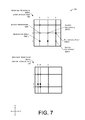
- FIG. 7 illustrates a moveable microphone array, configured to displace microphones to different spatial positions to form two or more microphone arrays.
- FIG. 8 is an illustrative process of determining a location of a sound source using two microphone arrays.
- FIG. 9 is an illustrative process of using a dynamically addressable microphone array and selecting two subsets of microphones therein to determine a location of a sound source.
- FIG. 10 is an illustrative process of setting a threshold distance for determining which of two or more arrays to use.
- Sound source localization is the process of determining from where in a particular space a sound originates, such as by determining a bearing and a distance relative to an origin.
- Sound sources include user speech, audible gestures, audio signaling devices, musical instruments, audio playback devices, mechanical systems, and so forth.
- the sound sources may include frequencies generally audible to the humans' ears or inaudible to the humans' ears, such as ultrasound.
- Localization is used in a variety of applications including quality control, equipment maintenance, user input in augmented reality environments, and so forth.
- Knowledge of a spatial position of a sound source may be used in a variety of ways including to identify a user or object, adjusted projected images in an augmented reality environment, select beam patterns to improve signal recovery, and so forth.
- Traditional systems have used a single array of microphones to localize a source of the sound.
- single arrays suffer from the disadvantage of introducing uncertainty or error in bearing and distance measurements depending upon factors such as the distance of the object from the origin. For example, a single large array may provide localization with a suitable level of accuracy when the sound source is distant from the array, but may provide erroneous results when the sound source is close to the array.
- Each microphone array contains a plurality of microphones configured to generate signal data in response to sound.
- the microphones in the array may be distributed in regular or irregular linear, planar, or three-dimensional arrangements.
- techniques for using data from the microphones in these arrays to localize the sound source may be selected based on a specified threshold. In some implementations this threshold may comprise a distance. For example, sound sources beyond a threshold distance value are localized using data from a large array while sound sources under the threshold distance are localized using data from a small array.
- the threshold may be determined by comparing localization results based on data from the different arrays with location information gathered using other sensors.
- the system may then be configured to use the array which provides more accurate results for a particular set of conditions, such as distance and bearing to the sound source.
- a spatial position of the sound source may be determined in the physical environment by various techniques including structured light, image capture, manual entry, and so forth.
- Structured light may involve projection of a pattern onto objects within a scene and may determine position based upon sensing the interaction of the objects with the pattern using an imaging device.
- the pattern may be regular, random, pseudo-random, and so forth.
- a structured light system may determine a user's face is at particular coordinates within in the room.
- a spatial position of the sound source may be identified in a planar manner, such as with reference to an azimuth, or in a three-dimensional manner, such as with reference to an azimuth and an elevation.
- the signal source may be localized with reference to a particular set of coordinates, such as azimuth, elevation, and distance from a known reference point, such as a defined pole or origin of the system.
- FIG. 1 shows an illustrative augmented reality environment 100 with an augmented reality functional node (ARFN) 102 having an associated computing device.
- ARFN augmented reality functional node
- additional ARFNs 102 ( 1 ), 102 ( 2 ), . . . , 102 (N) may be used.
- the ARFN 102 may be positioned in the physical environment, such as in the corners or center of the ceiling, on a tabletop, on a floor stand, and so forth. When active, one such ARFN 102 may generate an augmented reality environment incorporating some or all of the items in the scene such as real-world objects.
- a plurality of microphone arrays 104 may couple to a computing device 110 containing a processor 112 via an input/output interface 114 .
- Each of the microphone arrays 104 comprise a plurality of microphones. In some implementations one or more microphones may be shared between arrays. The microphones may be distributed in regular or irregular pattern. The pattern may be linear, planar, or three-dimensional. Microphones within the array may have different sensitivities, frequency responses, patterns, and so forth. Various microphone arrays are discussed in more detail below with regards to FIGS. 3-7 . The use of the microphone arrays and localization techniques as described herein with regards to augmented reality are for illustrative purposes only, and are not to be construed as a limitation.
- the ARFN 102 may incorporate or couple to input/output devices 106 .
- These input/output devices include projectors, cameras, microphones, other ARFNs 102 , other computing devices 110 , and so forth.
- the coupling between the computing device 110 and the input/output devices 106 may be via wire, fiber optic cable, or wireless connection.
- the network interface 108 is configured to couple the computing device 110 to a network such as a local area network, wide area network, wireless wide area network, and so forth.
- the network interface 108 may be used to transfer data between the computing device 110 and other devices such as other computing devices 110 , and cloud resources via the internet. For example, data from the microphone arrays 104 may be sent to a cloud resource such as a server for processing.
- the processor 112 may comprise one or more processors configured to execute instructions.
- the instructions may be stored in computer-readable storage media (“CRSM”) 116 , or in other memory accessible to the processor 112 such as in the cloud via the network interface 108 .
- CRSM computer-readable storage media
- the CRSM may be any available physical media accessible by a computing device to implement the instructions stored thereon.
- CRSM may include, but is not limited to, random access memory (“RAM”), read-only memory (“ROM”), electrically erasable programmable read-only memory (“EEPROM”), flash memory or other memory technology, compact disk read-only memory (“CD-ROM”), digital versatile disks (“DVD”) or other optical disk storage, magnetic cassettes, magnetic tape, magnetic disk storage or other magnetic storage devices, or any other medium which can be used to store the desired information and which can be accessed by a computing device.
- RAM random access memory
- ROM read-only memory
- EEPROM electrically erasable programmable read-only memory
- CD-ROM compact disk read-only memory
- DVD digital versatile disks
- An operating system module 118 is configured to manage hardware and services within and coupled to the computing device 110 for the benefit of other modules.
- An augmented reality module 120 is configured to maintain the augmented reality environment.
- a localization module 122 is configured to determine a location or direction of a sound source relative to the microphone arrays 104 based on data from the microphones in the arrays.
- the localization module 122 may use a variety of techniques including trilateration, time-difference-of-arrival, and so forth.
- Various time-difference-of-arrival techniques may be utilized. These include the VMRL technique described by Jean-Marc Valin, Francois Michaud, Jean Rouat, Dominic Letourneau as well as the linear intersection estimator also known as the BAS technique by Michael S. Brandstein, John E. Adcock, and Harvey F. Silverman.
- An array selection module 124 may be used by the localization module 122 to select which of the microphone arrays 104 to use data from in the localization process.
- the array selection module 124 may be configured to use one array rather than another based at least in part on a distance to the object. This implementation is discussed below in more detail with regards to FIG. 8 .
- the localization module 122 may utilize, at least in part, data including structured light, ranging data, and so forth as acquired via the input/output device 106 to determine a location of the sound source.
- data including structured light, ranging data, and so forth as acquired via the input/output device 106 to determine a location of the sound source.
- a structured light projector and camera may be used to determine the physical location of the user's head, from which sound signals may emanate.
- the signal data from the microphone arrays 104 and/or other input devices in the augmented reality environment may be stored in a signal datastore 128 .
- data acquired from the different microphone arrays 104 may be stored for later processing.
- Modules may be stored in the CRSM of the ARFN 102 , storage devices accessible on the local network, or cloud storage accessible the network interface 108 .
- the localization module 122 may be stored and executed within a cloud resource using data acquired by the microphone arrays 104 .
- FIG. 2 shows an illustrative schematic 200 of one example of a portion of an augmented reality functional node 102 and selected components including input/output devices 106 .
- the ARFN 102 is configured to scan at least a portion of a scene 202 and the objects therein.
- the ARFN 102 may also be configured to provide augmented reality output, such as images, sounds, and so forth.
- a chassis 204 holds the components of at least a portion of the ARFN 102 .
- a projector 206 that generates and projects images into the scene 202 . These images may be visible light images perceptible to the user, visible light images imperceptible to the user, images with non-visible light, or a combination thereof.
- This projector 206 may be implemented with any number of technologies capable of generating an image and projecting that image onto a surface within the environment. Suitable technologies include a digital micromirror device (DMD), liquid crystal on silicon display (LCOS), liquid crystal display, 3LCD, and so forth.
- the projector 206 has a projector field of view 208 which describes a particular solid angle.
- the projector field of view 208 may vary according to changes in the configuration of the projector. For example, the projector field of view 208 may narrow upon application of an optical zoom to the projector. In some implementations, a plurality of projectors 206 may be used.
- a camera 210 may also be disposed within the chassis 204 .
- the camera 210 is configured to image the scene in visible light wavelengths, non-visible light wavelengths, or both.
- the camera 210 has a camera field of view 212 which describes a particular solid angle.
- the camera field of view 212 may vary according to changes in the configuration of the camera 210 . For example, an optical zoom of the camera may narrow the camera field of view 212 .
- a plurality of cameras 210 may be used.
- the chassis 204 may be mounted with a fixed orientation, or be coupled via an actuator to a fixture such that the chassis 204 may move.
- Actuators may include piezoelectric actuators, motors, linear actuators, and other devices configured to displace or move the chassis 204 or components therein such as the projector 206 and/or the camera 210 .
- the actuator may comprise a pan motor 214 , tilt motor 216 , a roll motor 218 , and so forth.
- the pan motor 214 is configured to rotate the chassis 204 in a yawing motion changing the azimuth.
- the tilt motor 216 is configured to change the pitch of the chassis 204 changing the elevation.
- the roll motor 218 is configured to rotate the chassis 204 in a rolling motion. By panning, tilting, and/or rolling the chassis 204 , different views of the scene may be acquired.
- One or more microphones 220 may be disposed within the chassis 204 , or elsewhere within the scene such in the microphone arrays 104 .
- the microphone array 104 may include the one or more microphones 220 within the chassis 204 .
- These microphones 220 may be used to acquire input from the user, for echolocation, location determination of a sound, or to otherwise aid in the characterization of and receipt of input from the scene.
- the user may make a particular noise, such as a tap on a wall or snap of the fingers in a particular location, which are pre-designated as inputs.
- the user may alternatively use voice commands.
- One or more speakers 222 may also be present to provide for audible output.
- the speakers 222 may be used to provide output from a text-to-speech module or to playback pre-recorded audio.
- a transducer 224 may be present within the ARFN 102 , or elsewhere within the environment, and configured to detect and/or generate inaudible signals, such as infrasound or ultrasound. These inaudible signals may be used to provide for signaling between accessory devices and the ARFN 102 .
- a ranging system 226 may also be provided in the ARFN 102 .
- the ranging system 226 may be configured to provide distance, location, or distance and location information from the ARFN 102 to a scanned object or set of objects.
- the ranging system 226 may comprise radar, light detection and ranging (LIDAR), ultrasonic ranging, stereoscopic ranging, and so forth.
- the ranging system 226 may also provide direction information in some implementations.
- the transducer 224 , the microphones 220 , the speaker 222 , or a combination thereof may be configured to use echolocation or echo-ranging to determine distance and spatial characteristics.
- the ranging system 226 may comprise an acoustic transducer and the microphones 220 may be configured to detect a signal generated by the acoustic transducer.
- a set of ultrasonic transducers may be disposed such that each projects ultrasonic sound into a particular sector of the room.
- the microphones 220 may be configured to receive the ultrasonic signals, or dedicated ultrasonic microphones may be used. Given the known location of the microphones relative to one another, active sonar ranging and positioning may be provided.
- the computing device 110 is shown within the chassis 204 . However, in other implementations all or a portion of the computing device 110 may be disposed in another location and coupled to the ARFN 102 . This coupling may occur via wire, fiber optic cable, wirelessly, or a combination thereof. Furthermore, additional resources external to the ARFN 102 may be accessed, such as resources in another ARFN 102 accessible via the network interface 108 and a local area network, cloud resources accessible via a wide area network connection, or a combination thereof.
- the known projector/camera linear offset “O” may also be used to calculate distances, dimensioning, and otherwise aid in the characterization of objects within the scene 202 .
- the relative angle and size of the projector field of view 208 and camera field of view 212 may vary. Also, the angle of the projector 206 and the camera 210 relative to the chassis 204 may vary.
- the components of the ARFN 102 may be distributed in one or more locations within the environment 100 .
- the microphones 220 and the speakers 222 may be distributed throughout the scene.
- the projector 206 and the camera 210 may also be located in separate chassis 204 .
- the ARFN 102 may also include discrete portable signaling devices used by users to issue command attention inputs. For example, these may be acoustic clickers (audible or ultrasonic), electronic signaling devices such as infrared emitters, radio transmitters, and so forth.
- FIG. 3 shows an overhead view 300 of one implementation of the microphone arrays 104 in an augmented reality functional node 102 .
- a shared microphone 302 which is used in a first microphone array 104 ( 1 ) and a second microphone array 104 ( 2 ) is coupled to a support structure 304 .
- shared microphones are indicated with a solid white fill.
- the support structure 304 describes a cross with two linear members disposed perpendicular to one another each having length of D1 and D2 and an orthogonal member as shown in FIG. 4 below.
- the support structure 304 aids in maintaining a known pre-determined distance between the microphones 220 which may then be used in the localization of the sound signal.
- Microphones 220 ( 1 )-(M) are distributed along the support structure 304 , and may be designated into two or more arrays.
- the first microphone array 104 ( 1 ) shown here extends around a perimeter of the support structure at the ends of the linear members and includes the shared microphone 302 at the intersection of the linear members.
- the second microphone array 104 ( 2 ) comprises the shared microphone 302 and four microphones 220 disposed between the shared microphone 302 and the microphones of the first array 104 ( 1 ).
- the distribution of the microphones 220 within each of the arrays 104 may be symmetrical or asymmetrical. It is understood that the number and placement of the microphones 220 as well as the shape of the support structure 304 may vary.
- the support structure may describe a triangular, circular, or other geometric shape.
- an asymmetrical support structure shape, distribution of microphones, or both may be used.
- the first microphone array 104 ( 1 ) encompasses a first area while the second microphone array 104 ( 2 ) encompasses a second area which is smaller than the first area. These areas may be adjacent, overlap, or be exclusive of one another.
- a pole or origin 306 is a designated point among the arrays 104 from which a bearing and distance of the sound source is determined.
- the origin 306 may be coincident with a microphone, portion of the support structure 304 , or a point in space.
- a first zone 308 may be designated extending outwards from a threshold distance 310 , relative to the origin 306 .
- a second zone 312 extends from the origin 306 to the threshold distance 310 .
- the second zone 312 is depicted here as being circular. However, in other implementations the second zone 312 may be other symmetric or asymmetric shapes.
- a sound source 314 is shown here within the first zone 308 , at a distance 318 from the origin 306 which is outside the threshold distance 310 .
- the sound source 316 is shown producing emitted sound 316 , which is detected by the microphones 220 in the arrays 104 .
- the sound source may comprise a person talking, an acoustic signaling device, and so forth.
- the first microphone array 104 ( 1 ) may be selected by the array selection module 124 .
- Data from the first microphone array 104 ( 1 ) then provides data for the localization module 122 to determine the spatial location of the sound source 314 .
- the second microphone array 104 ( 2 ) may be selected by the array selection module 124 . As above, once selected, the second microphone array 104 ( 2 ) provides data for the localization module 122 to determine the spatial location of the sound source 314 .
- one or more characteristics such as frequency response, sensitivity, and so forth may vary between the microphones 220 in the first microphone array 104 ( 1 ) and those in the second microphone array 104 ( 2 ).
- the first microphone array 104 ( 1 ) may be configured to be more sensitive to sounds below 1 kHz while the second microphone array 104 ( 2 ) may be configured be more sensitive to sounds above 3 kHz.
- the support structure 304 may comprise part of the structure of a room.
- the microphones 220 may be mounted to the walls, ceilings, floor, and so forth within the room.
- the microphones 220 may be emplaced, and their position relative to one another determined through other sensing means, such as via the ranging system 226 , structured light scan, manual entry, and so forth.
- the microphones 220 may be placed at various locations within the room and their precise position relative to one another determined by the ranging system 226 using an optical range finder configured to detect an optical tag disposed upon each.
- a third microphone array may encompass an area larger than the first microphone array 104 ( 1 ). Or in another implementation the third microphone array may be smaller than the second microphone array 104 ( 2 ).
- FIG. 4 shows a side view 400 of the microphone arrays of FIG. 3 .
- the microphone arrays 104 may be configured with the microphones 220 disposed in a three-dimensional arrangement.
- a portion of the support structure 304 is configured to be orthogonal to the other members of the support structure 304 .
- the support structure 304 extends a distance D3 from the chassis 204 .
- the localization module 122 is able to more precisely locate the sound source 314 in space.
- the first zone 308 may be designated extending from the threshold distance 310 from the origin 306 outwards.
- the second zone 312 extends from the origin 306 to the threshold distance 310 .
- the second zone 312 as depicted here and in FIG. 3 describes a hemispherical volume. However, in other implementations the second zone 312 may be other symmetric or asymmetric shapes.
- the microphones 220 and microphone arrays 104 are configured to operate in a non-aqueous and gaseous medium having a density of less than about 100 kilograms per cubic meter.
- the microphone arrays 104 are configured to acquire audio signals in a standard atmosphere.
- FIG. 5 illustrates various microphone array configurations 500 incorporating a first and a second array. While the following configurations depict microphones arranged in rectilinear arrays, it is understood that other configurations are possible.
- the array may describe regular or irregular polygons having three or more sides.
- the polygons described by the first and second microphone arrays need not be the same.
- the first microphone array 104 ( 1 ) may describe a nonagon while the second microphone array 104 ( 2 ) may describe a hexagon.
- a center-nested configuration is depicted.
- the second microphone array 104 ( 2 ) is positioned within the center of the first microphone array 104 ( 1 ).
- an offset nested configuration 504 is depicted where the second microphone array 104 ( 2 ) is disposed at a position other than the center, but within a perimeter described by the first microphone array 104 ( 1 ).
- at least one microphone 302 is shared between the first microphone array 104 ( 1 ) and the second microphone array 104 ( 2 ). Sharing one or more microphones between arrays may provide several benefits including reducing costs by reducing overall microphone count, simplifying processing by providing a set of signals used by both arrays with common timing (as they originated at the same microphone), and so forth.
- an offset external configuration 506 may be used.
- the second microphone array 104 ( 2 ) is disposed such that at least a portion of the microphones in the second microphone array 104 ( 2 ) are at least partly outside of the perimeter formed by the first microphone array 104 .
- the second microphone array 104 ( 2 ) may be configured with a different set of microphones 220 , such that no microphone is shared between the arrays.
- the first microphone array 104 ( 1 ) and the second microphone array 104 ( 2 ) may also partially overlap one another in some implementations.
- At least a portion of the first microphone array 104 ( 1 ), the second microphone array 104 ( 2 ), or both may be configured to physically move.
- outlying microphones 508 which are disposed outside of the perimeter of the first microphone array 104 ( 1 ) may be configured to move between the position shown which is outside the perimeter and a position inside the perimeter.
- the configuration may switch between the offset external configuration 506 and one of the other configurations such as the offset nested configuration 504 .
- FIG. 6 illustrates a dynamically addressable microphone 600 array configured to form at least two microphone arrays.
- the dynamically addressable microphone array 600 is depicted here as a grid, but in other implementations other arrangements may be used, such as a hexagonal arrangement, or non-periodic arrangement such as a Penrose tiling.
- the grid is intentionally irregular such that squares within the grid are non-uniform.
- a regular grid having substantially the same grid spacing may be used.
- the microphones 220 within the dynamically addressable microphone array 600 are configured such that data from each microphone may be acquired and analyzed discretely. By varying which of the microphones acquire data (such as by turning them on or off), or by varying what data from particular microphones is analyzed, microphone arrays of different sizes and shapes may be formed. These different sizes and shapes may be selected to improve localization performance.
- the dynamically addressable microphone array 600 is described in terms of column headings A, B, C, D, and E and row headings of 1, 2, 3, 4, and 5. Microphones may be distributed at the intersections of the rows and columns, and the placement of that microphone described in relation to those headings. For example, microphone A1 is located at an upper-left-most corner while microphone E5 is at a lower-right-most corner.
- Inactive microphones 604 are depicted herein with light stippling. Inactive microphones 604 may be inactive from an operational or analytical point of view. For example, operationally inactive microphones may be deactivated such that they are not gathering data. Analytically inactive microphones may gather data, but the data acquired may be disregarded or discarded.
- a first dynamic configuration 606 is depicted, in which two microphone arrays have been defined within the dynamically addressable microphone array 600 .
- the first microphone array 104 ( 1 ) comprises four active microphones at A2, C2, A5, and C5.
- microphones active in the first microphone array 104 ( 1 ) are denoted with a crosshatch pattern.
- the second microphone array 104 ( 1 ) comprises four active microphones at A3, B3, A4, and B4. This configuration effectively forms a variation of the offset nested configuration 504 in which shared microphones are not used.
- the array selection module 124 may change the configuration of the arrays within the dynamically addressable microphone array 600 . This change may occur in response to localization data generated by the localization module 122 , changes in the position of the sound source 314 , presence of noise sources within the environment, and so forth.
- a second dynamic configuration 608 is depicted, such as may occur when the array selection module 124 determines another configuration is called for. For example, consider where the array 600 encompasses a large room and the sound source 314 such as a user has walked across the room to a location about in the center of the room. The first microphone array 104 ( 1 ) has been dynamically adjusted to activate microphones A2, A5, D2, and D5. Likewise, the second microphone array 104 ( 2 ) has been dynamically adjusted to activate microphones D1, E1, E2, and share microphone 302 which is present at location D2 with the first array 104 ( 1 ). This configuration is a variation of the offset external configuration 506 described above. By using this configuration, or other dynamic configurations of the available microphones, the localization module 122 is able to locate the sound source 314 within the environment.
- FIG. 7 illustrates a moveable microphone array 700 , configured to physically displace at least a portion of the microphones therein to different physical locations.
- This movement may include movement in one, two, or three dimensions. Movement may be accomplished with electric motors, pneumatic or hydraulic actuators, magnetic fields, and so forth.
- the movement may be at least partly in response to the localization module 122 or other modules in the system.
- the localization module 122 may move microphones in the moveable array 700 at least partly in response to the user moving from one position in the room to another, or to try and reduce interference from a noise source such as an operational air conditioning unit.
- a first arrangement 702 depicts the moveable microphone array 700 where seven of nine microphones are active at first positions.
- the general microphone configuration is a variation of an offset nested configuration 504 in which two microphones 302 ( 1 ) and 302 ( 2 ) are shared.
- the first microphone array 104 ( 1 ) comprises microphones A1, C1, A3, and shared microphones 302 ( 1 ) at C3 and 302 ( 2 ) in a center of the array at B2.
- the second microphone array 104 ( 2 ) comprises the shared microphones 302 ( 1 ) at C3 and 302 ( 2 ) at B2 as well as microphones at C2 and B3.
- the microphones are physically displaced, resulting in a second arrangement 704 of the moveable microphone array.
- the rows and columns have been displaced such that the microphones form a physically smaller first microphone array 104 ( 1 ) and second microphone array 104 ( 2 ).
- the arrangement of which microphones are active has also changed in that C3 is no longer shared.
- the second microphone array 104 ( 2 ) has been shifted from a bottom right of the array 700 to a bottom left of the array.
- the devices and techniques of the dynamically addressable microphone array 600 and the moveable microphone array 700 may be combined.
- the processes described in this disclosure may be implemented by the architectures described herein, or by other architectures. These processes are illustrated as a collection of blocks in a logical flow graph. Some of the blocks represent operations that can be implemented in hardware, software, or a combination thereof. In the context of software, the blocks represent computer-executable instructions stored on one or more computer-readable storage media that, when executed by one or more processors, perform the recited operations. Generally, computer-executable instructions include routines, programs, objects, components, data structures, and the like that perform particular functions or implement particular abstract data types. The order in which the operations are described is not intended to be construed as a limitation, and any number of the described blocks can be combined in any order or in parallel to implement the processes. It is understood that the following processes may be implemented on other architectures as well.
- FIG. 8 is an illustrative process 800 of determining a location of a sound source using two or more microphone arrays.
- a first signal data of a signal source acquired at a first microphone array is retrieved.
- a first distance to the signal source relative to a pre-determined point is determined. In some implementations a bearing, or a distance and a bearing may be determined.
- other thresholds may be used, such as bearing, distance and bearing, and so forth.
- This threshold may be statically set or determined dynamically.
- the localization module 122 may be configured to determine a possible location of the signal source using a depth sensor and set the threshold distance based at least in part upon a correspondence of the possible location to the first location or second location. In this way, the system may be calibrated to select the array which generates location data which most accurately reflects the true position of the sound source 314 , at least as determined by the depth sensor.
- the depth sensor may comprise structured light emitted by a projector. This is discussed in more depth below with regards to FIG. 10 .
- a threshold value using one or more attributes other than distance may be used. These attributes may include a determined spatial location of the sound source, a distance of the sound source from a pre-determined point, or a signal-to-noise-ratio of a signal in the data. For example, a sound source in a particular region of a room may use a particular microphone array, regardless of distance.
- the process proceeds to 808 .
- a first location of the source based at least in part on the first signal data is determined.
- second signal data of the signal source acquired at a second microphone array is retrieved.
- This second microphone array comprises a physical configuration of microphones which differs at least in part from the first microphone array.
- the first microphone array and second microphone array are configured such that they intersect at one or more microphones but are non-identical overall.
- a location of the source relative to the microphone array is determined based at least in part on the second signal data is determined.
- the first signal data and the second signal data may be acquired at substantially the same time.
- FIG. 9 is an illustrative process 900 of using the dynamically addressable microphone array 600 or the moveable microphone array 700 .
- the microphones configured to acquire data from the sound source are individually addressable. For example, four or more microphones, or the data therefrom, out of an array of twenty-five may be configured in the first dynamic configuration 606 to form the first microphone array 104 ( 1 ) as shown in FIG. 6 , while other microphones form the second microphone array 104 ( 2 ).
- three or more microphones may be used, from which two or more arrays may be configured.
- microphones may be coupled with direction-selective surfaces, allowing localization of a sound with two microphones.
- three microphones may comprise the first and second array, where the first and the second array each comprise two microphones having direction-selective surfaces.
- Each microphone array thus comprises a plurality of individual microphones which are a subset of the available microphones.
- designated microphone arrays having different physical arrangements, counts of microphones, and so forth may be selected.
- the data acquired by these two or more subsets of microphones is used to determine a location of a sound source.
- data is acquired from a sound source at a plurality of microphones.
- a plurality of microphones For example, the dynamic microphone array 600 or moveable microphone array 700 .
- a first subset of the plurality of microphones is designated as a first microphone array.
- the first microphone array 104 ( 1 ) of the first dynamic configuration 606 of FIG. 6 is designated as a first microphone array.
- a second, different subset of the plurality of microphones is designated as a second microphone array.
- the first subset and second subset are configured such that the subsets include at least one common microphone. Stated another way, the first and second subsets intersect with one or more microphones but are non-identical.
- the second dynamic configuration 608 comprises the first subset of the first microphone array 104 ( 1 ) and the second subset of the second microphone array 104 ( 2 ) which intersect at the shared microphone 302 .
- the first subset of microphones and the second subset of microphones are configured such that the second subset comprises microphones physically disposed in a spatial arrangement encompassing an area less than the first subset.
- the spatial arrangements and encompassing areas may be immediately adjacent, overlap in some implementations, or may be discrete from one another.
- at least a portion of the second subset may be disposed within the second subset.
- the first dynamic configuration 606 of FIG. 6 The first subset and the second subset together may use less than all of the plurality of microphones. Thus, there may be some inactive microphones 604 .
- a first location of the sound source is determined based on data from the first subset.
- the localization module 122 may use a variety of techniques including trilateration, time-difference-of-arrival, and so forth to determine the location.
- Various time-difference-of-arrival techniques may be utilized. These include the VMRL technique described by Jean-Marc Valin, Francois Michaud, Jean Rouat, Dominic Letourneau as well as the linear intersection estimator also known as the BAS technique by Michael S. Brandstein, John E. Adcock, and Harvey F. Silverman.
- a second location of the sound source is determined based on data from the second subset of the plurality of microphones.
- the determined location having a lowest error is selected. The lowest error may be determined based on uncertainty in the acquired data, comparison with other sensor data such as from an imaging system, pre-defined constraints such as known room dimensions, and so forth.
- the determined location may be used by other modules, such as the augmented reality module 120 to process the sound signal as an input, for tracking, and so forth.
- the designation of the subsets may occur prior to data acquisition. For example, the subsets may be designated, and data from the microphones in the subsets stored or processed while data from microphones not in the subsets is discarded or not acquired.
- FIG. 10 is an illustrative process 1000 of setting a threshold distance for determining which of two or more arrays to use.
- the threshold distance 310 may be configured such that one of a plurality of microphone arrays or subsets of microphones provide accurate data for use by the localization module 122 to determine the position of the sound source 314 .
- a first location of a sound source using data from a first microphone array is determined.
- a second location of a sound source is determined using data from a second microphone array having at least a portion of a physical configuration of microphones different from the first microphone array.
- a possible location of the sound source is determined using one or more sensors other than the microphones.
- images acquired by the camera 210 within the ARFN 102 chassis 204 may be used in conjunction with position information from the pan motor 214 , tilt motor 216 , and roll motor 218 to provide a possible location.
- a LIDAR scanner may locate the user's face in the room which may be designated as a sound source for speech.
- a threshold distance for selection of the first microphone array or the second microphone array is set based at least in part upon correspondence of the first and second locations to the possible location. For example, consider where the first location is (203, 127, 51), the second location is (191, 135, 70), and the possible location is (196, 125, 53). The first location is closest to the possible location, and thus is deemed to correspond most closely to the possible location. This correspondence may be based on a magnitude of a distance vector, error analysis, and so forth.
Abstract
Description
Claims (20)
Priority Applications (2)
| Application Number | Priority Date | Filing Date | Title |
|---|---|---|---|
| US14/658,001 US9489948B1 (en) | 2011-11-28 | 2015-03-13 | Sound source localization using multiple microphone arrays |
| US16/017,908 US10966022B1 (en) | 2011-11-28 | 2018-06-25 | Sound source localization using multiple microphone arrays |
Applications Claiming Priority (2)
| Application Number | Priority Date | Filing Date | Title |
|---|---|---|---|
| US13/305,189 US8983089B1 (en) | 2011-11-28 | 2011-11-28 | Sound source localization using multiple microphone arrays |
| US14/658,001 US9489948B1 (en) | 2011-11-28 | 2015-03-13 | Sound source localization using multiple microphone arrays |
Related Parent Applications (1)
| Application Number | Title | Priority Date | Filing Date |
|---|---|---|---|
| US13/305,189 Continuation US8983089B1 (en) | 2011-11-28 | 2011-11-28 | Sound source localization using multiple microphone arrays |
Related Child Applications (1)
| Application Number | Title | Priority Date | Filing Date |
|---|---|---|---|
| US201615344350A Continuation | 2011-11-28 | 2016-11-04 |
Publications (1)
| Publication Number | Publication Date |
|---|---|
| US9489948B1 true US9489948B1 (en) | 2016-11-08 |
Family
ID=52632309
Family Applications (3)
| Application Number | Title | Priority Date | Filing Date |
|---|---|---|---|
| US13/305,189 Expired - Fee Related US8983089B1 (en) | 2011-11-28 | 2011-11-28 | Sound source localization using multiple microphone arrays |
| US14/658,001 Active US9489948B1 (en) | 2011-11-28 | 2015-03-13 | Sound source localization using multiple microphone arrays |
| US16/017,908 Active US10966022B1 (en) | 2011-11-28 | 2018-06-25 | Sound source localization using multiple microphone arrays |
Family Applications Before (1)
| Application Number | Title | Priority Date | Filing Date |
|---|---|---|---|
| US13/305,189 Expired - Fee Related US8983089B1 (en) | 2011-11-28 | 2011-11-28 | Sound source localization using multiple microphone arrays |
Family Applications After (1)
| Application Number | Title | Priority Date | Filing Date |
|---|---|---|---|
| US16/017,908 Active US10966022B1 (en) | 2011-11-28 | 2018-06-25 | Sound source localization using multiple microphone arrays |
Country Status (1)
| Country | Link |
|---|---|
| US (3) | US8983089B1 (en) |
Cited By (121)
| Publication number | Priority date | Publication date | Assignee | Title |
|---|---|---|---|---|
| US9648422B2 (en) | 2012-06-28 | 2017-05-09 | Sonos, Inc. | Concurrent multi-loudspeaker calibration with a single measurement |
| US9668049B2 (en) | 2012-06-28 | 2017-05-30 | Sonos, Inc. | Playback device calibration user interfaces |
| US9690271B2 (en) | 2012-06-28 | 2017-06-27 | Sonos, Inc. | Speaker calibration |
| US9693164B1 (en) | 2016-08-05 | 2017-06-27 | Sonos, Inc. | Determining direction of networked microphone device relative to audio playback device |
| US9693165B2 (en) | 2015-09-17 | 2017-06-27 | Sonos, Inc. | Validation of audio calibration using multi-dimensional motion check |
| US9690539B2 (en) | 2012-06-28 | 2017-06-27 | Sonos, Inc. | Speaker calibration user interface |
| US9706323B2 (en) | 2014-09-09 | 2017-07-11 | Sonos, Inc. | Playback device calibration |
| US9736572B2 (en) | 2012-08-31 | 2017-08-15 | Sonos, Inc. | Playback based on received sound waves |
| US9743208B2 (en) | 2014-03-17 | 2017-08-22 | Sonos, Inc. | Playback device configuration based on proximity detection |
| US9743204B1 (en) | 2016-09-30 | 2017-08-22 | Sonos, Inc. | Multi-orientation playback device microphones |
| US9743207B1 (en) | 2016-01-18 | 2017-08-22 | Sonos, Inc. | Calibration using multiple recording devices |
| US9749763B2 (en) | 2014-09-09 | 2017-08-29 | Sonos, Inc. | Playback device calibration |
| US9763018B1 (en) | 2016-04-12 | 2017-09-12 | Sonos, Inc. | Calibration of audio playback devices |
| US9772817B2 (en) | 2016-02-22 | 2017-09-26 | Sonos, Inc. | Room-corrected voice detection |
| US9781533B2 (en) | 2015-07-28 | 2017-10-03 | Sonos, Inc. | Calibration error conditions |
| US9794720B1 (en) | 2016-09-22 | 2017-10-17 | Sonos, Inc. | Acoustic position measurement |
| US9794710B1 (en) | 2016-07-15 | 2017-10-17 | Sonos, Inc. | Spatial audio correction |
| US9811314B2 (en) | 2016-02-22 | 2017-11-07 | Sonos, Inc. | Metadata exchange involving a networked playback system and a networked microphone system |
| US9860662B2 (en) | 2016-04-01 | 2018-01-02 | Sonos, Inc. | Updating playback device configuration information based on calibration data |
| US9860670B1 (en) | 2016-07-15 | 2018-01-02 | Sonos, Inc. | Spectral correction using spatial calibration |
| US9864574B2 (en) | 2016-04-01 | 2018-01-09 | Sonos, Inc. | Playback device calibration based on representation spectral characteristics |
| US9872119B2 (en) | 2014-03-17 | 2018-01-16 | Sonos, Inc. | Audio settings of multiple speakers in a playback device |
| US9883142B1 (en) | 2017-03-21 | 2018-01-30 | Cisco Technology, Inc. | Automated collaboration system |
| US9891881B2 (en) | 2014-09-09 | 2018-02-13 | Sonos, Inc. | Audio processing algorithm database |
| US9930470B2 (en) | 2011-12-29 | 2018-03-27 | Sonos, Inc. | Sound field calibration using listener localization |
| US9942678B1 (en) | 2016-09-27 | 2018-04-10 | Sonos, Inc. | Audio playback settings for voice interaction |
| US9947316B2 (en) | 2016-02-22 | 2018-04-17 | Sonos, Inc. | Voice control of a media playback system |
| US9952825B2 (en) | 2014-09-09 | 2018-04-24 | Sonos, Inc. | Audio processing algorithms |
| US9965247B2 (en) | 2016-02-22 | 2018-05-08 | Sonos, Inc. | Voice controlled media playback system based on user profile |
| US9978390B2 (en) | 2016-06-09 | 2018-05-22 | Sonos, Inc. | Dynamic player selection for audio signal processing |
| US10003899B2 (en) | 2016-01-25 | 2018-06-19 | Sonos, Inc. | Calibration with particular locations |
| US10051366B1 (en) | 2017-09-28 | 2018-08-14 | Sonos, Inc. | Three-dimensional beam forming with a microphone array |
| US10095470B2 (en) | 2016-02-22 | 2018-10-09 | Sonos, Inc. | Audio response playback |
| US10097939B2 (en) | 2016-02-22 | 2018-10-09 | Sonos, Inc. | Compensation for speaker nonlinearities |
| US10115400B2 (en) | 2016-08-05 | 2018-10-30 | Sonos, Inc. | Multiple voice services |
| US10127006B2 (en) | 2014-09-09 | 2018-11-13 | Sonos, Inc. | Facilitating calibration of an audio playback device |
| US10134399B2 (en) | 2016-07-15 | 2018-11-20 | Sonos, Inc. | Contextualization of voice inputs |
| US10152969B2 (en) | 2016-07-15 | 2018-12-11 | Sonos, Inc. | Voice detection by multiple devices |
| US10181323B2 (en) | 2016-10-19 | 2019-01-15 | Sonos, Inc. | Arbitration-based voice recognition |
| US10264030B2 (en) | 2016-02-22 | 2019-04-16 | Sonos, Inc. | Networked microphone device control |
| US10284983B2 (en) | 2015-04-24 | 2019-05-07 | Sonos, Inc. | Playback device calibration user interfaces |
| US10291999B1 (en) | 2018-03-29 | 2019-05-14 | Cae Inc. | Method and system for validating a position of a microphone |
| US10299061B1 (en) | 2018-08-28 | 2019-05-21 | Sonos, Inc. | Playback device calibration |
| US10367948B2 (en) | 2017-01-13 | 2019-07-30 | Shure Acquisition Holdings, Inc. | Post-mixing acoustic echo cancellation systems and methods |
| US10372406B2 (en) | 2016-07-22 | 2019-08-06 | Sonos, Inc. | Calibration interface |
| US20190268695A1 (en) * | 2017-06-12 | 2019-08-29 | Ryo Tanaka | Method for accurately calculating the direction of arrival of sound at a microphone array |
| US10445057B2 (en) | 2017-09-08 | 2019-10-15 | Sonos, Inc. | Dynamic computation of system response volume |
| US10446165B2 (en) | 2017-09-27 | 2019-10-15 | Sonos, Inc. | Robust short-time fourier transform acoustic echo cancellation during audio playback |
| US10459684B2 (en) | 2016-08-05 | 2019-10-29 | Sonos, Inc. | Calibration of a playback device based on an estimated frequency response |
| US10466962B2 (en) | 2017-09-29 | 2019-11-05 | Sonos, Inc. | Media playback system with voice assistance |
| USD865723S1 (en) | 2015-04-30 | 2019-11-05 | Shure Acquisition Holdings, Inc | Array microphone assembly |
| US10475449B2 (en) | 2017-08-07 | 2019-11-12 | Sonos, Inc. | Wake-word detection suppression |
| US10482868B2 (en) | 2017-09-28 | 2019-11-19 | Sonos, Inc. | Multi-channel acoustic echo cancellation |
| US10573321B1 (en) | 2018-09-25 | 2020-02-25 | Sonos, Inc. | Voice detection optimization based on selected voice assistant service |
| US10585639B2 (en) | 2015-09-17 | 2020-03-10 | Sonos, Inc. | Facilitating calibration of an audio playback device |
| US10587430B1 (en) | 2018-09-14 | 2020-03-10 | Sonos, Inc. | Networked devices, systems, and methods for associating playback devices based on sound codes |
| US10586540B1 (en) | 2019-06-12 | 2020-03-10 | Sonos, Inc. | Network microphone device with command keyword conditioning |
| US10602268B1 (en) | 2018-12-20 | 2020-03-24 | Sonos, Inc. | Optimization of network microphone devices using noise classification |
| US10621981B2 (en) | 2017-09-28 | 2020-04-14 | Sonos, Inc. | Tone interference cancellation |
| CN111182387A (en) * | 2019-12-03 | 2020-05-19 | 广东小天才科技有限公司 | Learning interaction method and intelligent sound box |
| US10664224B2 (en) | 2015-04-24 | 2020-05-26 | Sonos, Inc. | Speaker calibration user interface |
| US10674260B1 (en) | 2018-11-20 | 2020-06-02 | Microsoft Technology Licensing, Llc | Smart speaker system with microphone room calibration |
| US10681460B2 (en) | 2018-06-28 | 2020-06-09 | Sonos, Inc. | Systems and methods for associating playback devices with voice assistant services |
| US10692518B2 (en) | 2018-09-29 | 2020-06-23 | Sonos, Inc. | Linear filtering for noise-suppressed speech detection via multiple network microphone devices |
| US10734965B1 (en) | 2019-08-12 | 2020-08-04 | Sonos, Inc. | Audio calibration of a portable playback device |
| US10797667B2 (en) | 2018-08-28 | 2020-10-06 | Sonos, Inc. | Audio notifications |
| US10818290B2 (en) | 2017-12-11 | 2020-10-27 | Sonos, Inc. | Home graph |
| US10847178B2 (en) | 2018-05-18 | 2020-11-24 | Sonos, Inc. | Linear filtering for noise-suppressed speech detection |
| US10867604B2 (en) | 2019-02-08 | 2020-12-15 | Sonos, Inc. | Devices, systems, and methods for distributed voice processing |
| US10871943B1 (en) | 2019-07-31 | 2020-12-22 | Sonos, Inc. | Noise classification for event detection |
| US10878811B2 (en) | 2018-09-14 | 2020-12-29 | Sonos, Inc. | Networked devices, systems, and methods for intelligently deactivating wake-word engines |
| US10880650B2 (en) | 2017-12-10 | 2020-12-29 | Sonos, Inc. | Network microphone devices with automatic do not disturb actuation capabilities |
| US10959029B2 (en) | 2018-05-25 | 2021-03-23 | Sonos, Inc. | Determining and adapting to changes in microphone performance of playback devices |
| US10979806B1 (en) | 2018-05-03 | 2021-04-13 | Apple Inc. | Audio system having audio and ranging components |
| US11024331B2 (en) | 2018-09-21 | 2021-06-01 | Sonos, Inc. | Voice detection optimization using sound metadata |
| US11076035B2 (en) | 2018-08-28 | 2021-07-27 | Sonos, Inc. | Do not disturb feature for audio notifications |
| US11100923B2 (en) | 2018-09-28 | 2021-08-24 | Sonos, Inc. | Systems and methods for selective wake word detection using neural network models |
| US11106423B2 (en) | 2016-01-25 | 2021-08-31 | Sonos, Inc. | Evaluating calibration of a playback device |
| US11120794B2 (en) | 2019-05-03 | 2021-09-14 | Sonos, Inc. | Voice assistant persistence across multiple network microphone devices |
| US11132989B2 (en) | 2018-12-13 | 2021-09-28 | Sonos, Inc. | Networked microphone devices, systems, and methods of localized arbitration |
| US11138975B2 (en) | 2019-07-31 | 2021-10-05 | Sonos, Inc. | Locally distributed keyword detection |
| US11138969B2 (en) | 2019-07-31 | 2021-10-05 | Sonos, Inc. | Locally distributed keyword detection |
| US11175880B2 (en) | 2018-05-10 | 2021-11-16 | Sonos, Inc. | Systems and methods for voice-assisted media content selection |
| US11183181B2 (en) | 2017-03-27 | 2021-11-23 | Sonos, Inc. | Systems and methods of multiple voice services |
| US11183183B2 (en) | 2018-12-07 | 2021-11-23 | Sonos, Inc. | Systems and methods of operating media playback systems having multiple voice assistant services |
| US11189286B2 (en) | 2019-10-22 | 2021-11-30 | Sonos, Inc. | VAS toggle based on device orientation |
| US11200894B2 (en) | 2019-06-12 | 2021-12-14 | Sonos, Inc. | Network microphone device with command keyword eventing |
| US11200900B2 (en) | 2019-12-20 | 2021-12-14 | Sonos, Inc. | Offline voice control |
| US11200889B2 (en) | 2018-11-15 | 2021-12-14 | Sonos, Inc. | Dilated convolutions and gating for efficient keyword spotting |
| US11206484B2 (en) | 2018-08-28 | 2021-12-21 | Sonos, Inc. | Passive speaker authentication |
| US20210400415A1 (en) * | 2017-09-29 | 2021-12-23 | Apple Inc. | 3d audio rendering using volumetric audio rendering and scripted audio level-of-detail |
| USD944776S1 (en) | 2020-05-05 | 2022-03-01 | Shure Acquisition Holdings, Inc. | Audio device |
| US11297426B2 (en) | 2019-08-23 | 2022-04-05 | Shure Acquisition Holdings, Inc. | One-dimensional array microphone with improved directivity |
| US11297423B2 (en) | 2018-06-15 | 2022-04-05 | Shure Acquisition Holdings, Inc. | Endfire linear array microphone |
| US11302347B2 (en) | 2019-05-31 | 2022-04-12 | Shure Acquisition Holdings, Inc. | Low latency automixer integrated with voice and noise activity detection |
| US11303981B2 (en) | 2019-03-21 | 2022-04-12 | Shure Acquisition Holdings, Inc. | Housings and associated design features for ceiling array microphones |
| US11308962B2 (en) | 2020-05-20 | 2022-04-19 | Sonos, Inc. | Input detection windowing |
| US11308958B2 (en) | 2020-02-07 | 2022-04-19 | Sonos, Inc. | Localized wakeword verification |
| US11310596B2 (en) | 2018-09-20 | 2022-04-19 | Shure Acquisition Holdings, Inc. | Adjustable lobe shape for array microphones |
| US11315556B2 (en) | 2019-02-08 | 2022-04-26 | Sonos, Inc. | Devices, systems, and methods for distributed voice processing by transmitting sound data associated with a wake word to an appropriate device for identification |
| US11343614B2 (en) | 2018-01-31 | 2022-05-24 | Sonos, Inc. | Device designation of playback and network microphone device arrangements |
| US11350229B2 (en) | 2018-03-29 | 2022-05-31 | Cae Inc. | Method and system for determining a position of a microphone |
| US11361756B2 (en) | 2019-06-12 | 2022-06-14 | Sonos, Inc. | Conditional wake word eventing based on environment |
| US11388512B2 (en) | 2018-02-22 | 2022-07-12 | Nomono As | Positioning sound sources |
| US11438691B2 (en) | 2019-03-21 | 2022-09-06 | Shure Acquisition Holdings, Inc. | Auto focus, auto focus within regions, and auto placement of beamformed microphone lobes with inhibition functionality |
| US11445294B2 (en) | 2019-05-23 | 2022-09-13 | Shure Acquisition Holdings, Inc. | Steerable speaker array, system, and method for the same |
| US11482224B2 (en) | 2020-05-20 | 2022-10-25 | Sonos, Inc. | Command keywords with input detection windowing |
| US11494158B2 (en) | 2018-05-31 | 2022-11-08 | Shure Acquisition Holdings, Inc. | Augmented reality microphone pick-up pattern visualization |
| US11496830B2 (en) | 2019-09-24 | 2022-11-08 | Samsung Electronics Co., Ltd. | Methods and systems for recording mixed audio signal and reproducing directional audio |
| US11523212B2 (en) | 2018-06-01 | 2022-12-06 | Shure Acquisition Holdings, Inc. | Pattern-forming microphone array |
| US11551700B2 (en) | 2021-01-25 | 2023-01-10 | Sonos, Inc. | Systems and methods for power-efficient keyword detection |
| US11552611B2 (en) | 2020-02-07 | 2023-01-10 | Shure Acquisition Holdings, Inc. | System and method for automatic adjustment of reference gain |
| US11556307B2 (en) | 2020-01-31 | 2023-01-17 | Sonos, Inc. | Local voice data processing |
| US11558693B2 (en) | 2019-03-21 | 2023-01-17 | Shure Acquisition Holdings, Inc. | Auto focus, auto focus within regions, and auto placement of beamformed microphone lobes with inhibition and voice activity detection functionality |
| US11562740B2 (en) | 2020-01-07 | 2023-01-24 | Sonos, Inc. | Voice verification for media playback |
| US11678109B2 (en) | 2015-04-30 | 2023-06-13 | Shure Acquisition Holdings, Inc. | Offset cartridge microphones |
| US11698771B2 (en) | 2020-08-25 | 2023-07-11 | Sonos, Inc. | Vocal guidance engines for playback devices |
| US11706562B2 (en) | 2020-05-29 | 2023-07-18 | Shure Acquisition Holdings, Inc. | Transducer steering and configuration systems and methods using a local positioning system |
| US11727919B2 (en) | 2020-05-20 | 2023-08-15 | Sonos, Inc. | Memory allocation for keyword spotting engines |
| US11785380B2 (en) | 2021-01-28 | 2023-10-10 | Shure Acquisition Holdings, Inc. | Hybrid audio beamforming system |
| US11899519B2 (en) | 2018-10-23 | 2024-02-13 | Sonos, Inc. | Multiple stage network microphone device with reduced power consumption and processing load |
Families Citing this family (25)
| Publication number | Priority date | Publication date | Assignee | Title |
|---|---|---|---|---|
| US10045321B2 (en) | 2010-12-30 | 2018-08-07 | Staton Techiya, Llc | Information processing using a population of data acquisition devices |
| US11452153B2 (en) * | 2012-05-01 | 2022-09-20 | Lisnr, Inc. | Pairing and gateway connection using sonic tones |
| KR102317364B1 (en) * | 2012-05-01 | 2021-10-25 | 엘아이에스엔알, 인크. | Systems and methods for content delivery and management |
| US9560446B1 (en) * | 2012-06-27 | 2017-01-31 | Amazon Technologies, Inc. | Sound source locator with distributed microphone array |
| US10750132B2 (en) * | 2013-03-14 | 2020-08-18 | Pelco, Inc. | System and method for audio source localization using multiple audio sensors |
| JP6149818B2 (en) * | 2014-07-18 | 2017-06-21 | 沖電気工業株式会社 | Sound collecting / reproducing system, sound collecting / reproducing apparatus, sound collecting / reproducing method, sound collecting / reproducing program, sound collecting system and reproducing system |
| CN107005256B (en) | 2014-10-15 | 2021-02-09 | 灵思耳有限公司 | Inaudible signaling tones |
| US10009676B2 (en) * | 2014-11-03 | 2018-06-26 | Storz Endoskop Produktions Gmbh | Voice control system with multiple microphone arrays |
| US11233582B2 (en) | 2016-03-25 | 2022-01-25 | Lisnr, Inc. | Local tone generation |
| US9959342B2 (en) * | 2016-06-28 | 2018-05-01 | Microsoft Technology Licensing, Llc | Audio augmented reality system |
| EP3343348A1 (en) | 2016-12-30 | 2018-07-04 | Nokia Technologies Oy | An apparatus and associated methods |
| JP7051876B6 (en) | 2017-01-27 | 2023-08-18 | シュアー アクイジッション ホールディングス インコーポレイテッド | Array microphone module and system |
| US10104484B1 (en) * | 2017-03-02 | 2018-10-16 | Steven Kenneth Bradford | System and method for geolocating emitted acoustic signals from a source entity |
| US11189295B2 (en) | 2017-09-28 | 2021-11-30 | Lisnr, Inc. | High bandwidth sonic tone generation |
| US10826623B2 (en) | 2017-12-19 | 2020-11-03 | Lisnr, Inc. | Phase shift keyed signaling tone |
| CN108132457A (en) * | 2017-12-22 | 2018-06-08 | 景晖 | The voice arrival bearing method of estimation and device of a kind of determining position |
| US10741037B2 (en) * | 2018-05-16 | 2020-08-11 | Avaya Inc. | Method and system for detecting inaudible sounds |
| US10540960B1 (en) * | 2018-09-05 | 2020-01-21 | International Business Machines Corporation | Intelligent command filtering using cones of authentication in an internet of things (IoT) computing environment |
| US11109133B2 (en) | 2018-09-21 | 2021-08-31 | Shure Acquisition Holdings, Inc. | Array microphone module and system |
| CN111383650A (en) * | 2018-12-28 | 2020-07-07 | 深圳市优必选科技有限公司 | Robot and audio data processing method thereof |
| US11257242B2 (en) * | 2018-12-31 | 2022-02-22 | Wipro Limited | Method and device for determining operation of an autonomous device |
| CN110716178A (en) * | 2019-09-17 | 2020-01-21 | 苏宁智能终端有限公司 | Full sound field oriented sound source positioning method and device |
| CN111544030B (en) * | 2020-05-20 | 2023-06-20 | 京东方科技集团股份有限公司 | Stethoscope, diagnostic device and diagnostic method |
| US11856147B2 (en) | 2022-01-04 | 2023-12-26 | International Business Machines Corporation | Method to protect private audio communications |
| CN115015838B (en) * | 2022-08-04 | 2022-12-09 | 荣耀终端有限公司 | Positioning method and sound source positioning system |
Citations (9)
| Publication number | Priority date | Publication date | Assignee | Title |
|---|---|---|---|---|
| US20040175006A1 (en) * | 2003-03-06 | 2004-09-09 | Samsung Electronics Co., Ltd. | Microphone array, method and apparatus for forming constant directivity beams using the same, and method and apparatus for estimating acoustic source direction using the same |
| US7418392B1 (en) | 2003-09-25 | 2008-08-26 | Sensory, Inc. | System and method for controlling the operation of a device by voice commands |
| US7720683B1 (en) | 2003-06-13 | 2010-05-18 | Sensory, Inc. | Method and apparatus of specifying and performing speech recognition operations |
| US20110002469A1 (en) | 2008-03-03 | 2011-01-06 | Nokia Corporation | Apparatus for Capturing and Rendering a Plurality of Audio Channels |
| WO2011088053A2 (en) | 2010-01-18 | 2011-07-21 | Apple Inc. | Intelligent automated assistant |
| US20120076316A1 (en) | 2010-09-24 | 2012-03-29 | Manli Zhu | Microphone Array System |
| US8155331B2 (en) * | 2006-05-10 | 2012-04-10 | Honda Motor Co., Ltd. | Sound source tracking system, method and robot |
| US20120223885A1 (en) | 2011-03-02 | 2012-09-06 | Microsoft Corporation | Immersive display experience |
| US8510110B2 (en) * | 2006-06-22 | 2013-08-13 | Microsoft Corporation | Identification of people using multiple types of input |
Family Cites Families (9)
| Publication number | Priority date | Publication date | Assignee | Title |
|---|---|---|---|---|
| US7970151B2 (en) * | 2004-10-15 | 2011-06-28 | Lifesize Communications, Inc. | Hybrid beamforming |
| US7995768B2 (en) * | 2005-01-27 | 2011-08-09 | Yamaha Corporation | Sound reinforcement system |
| ATE410346T1 (en) * | 2006-08-04 | 2008-10-15 | Harman Becker Automotive Sys | METHOD AND SYSTEM FOR PROCESSING VOICE COMMANDS IN A VEHICLE ENVIRONMENT |
| US8767975B2 (en) | 2007-06-21 | 2014-07-01 | Bose Corporation | Sound discrimination method and apparatus |
| CN101874404B (en) | 2007-09-24 | 2013-09-18 | 高通股份有限公司 | Enhanced interface for voice and video communications |
| DE102008029352A1 (en) * | 2008-06-20 | 2009-12-31 | Fraunhofer-Gesellschaft zur Förderung der angewandten Forschung e.V. | Apparatus, method and computer program for locating a sound source |
| US9226069B2 (en) | 2010-10-29 | 2015-12-29 | Qualcomm Incorporated | Transitioning multiple microphones from a first mode to a second mode |
| US9615172B2 (en) * | 2012-10-04 | 2017-04-04 | Siemens Aktiengesellschaft | Broadband sensor location selection using convex optimization in very large scale arrays |
| US9491033B1 (en) * | 2013-04-22 | 2016-11-08 | Amazon Technologies, Inc. | Automatic content transfer |
-
2011
- 2011-11-28 US US13/305,189 patent/US8983089B1/en not_active Expired - Fee Related
-
2015
- 2015-03-13 US US14/658,001 patent/US9489948B1/en active Active
-
2018
- 2018-06-25 US US16/017,908 patent/US10966022B1/en active Active
Patent Citations (10)
| Publication number | Priority date | Publication date | Assignee | Title |
|---|---|---|---|---|
| US20040175006A1 (en) * | 2003-03-06 | 2004-09-09 | Samsung Electronics Co., Ltd. | Microphone array, method and apparatus for forming constant directivity beams using the same, and method and apparatus for estimating acoustic source direction using the same |
| US7720683B1 (en) | 2003-06-13 | 2010-05-18 | Sensory, Inc. | Method and apparatus of specifying and performing speech recognition operations |
| US7418392B1 (en) | 2003-09-25 | 2008-08-26 | Sensory, Inc. | System and method for controlling the operation of a device by voice commands |
| US7774204B2 (en) | 2003-09-25 | 2010-08-10 | Sensory, Inc. | System and method for controlling the operation of a device by voice commands |
| US8155331B2 (en) * | 2006-05-10 | 2012-04-10 | Honda Motor Co., Ltd. | Sound source tracking system, method and robot |
| US8510110B2 (en) * | 2006-06-22 | 2013-08-13 | Microsoft Corporation | Identification of people using multiple types of input |
| US20110002469A1 (en) | 2008-03-03 | 2011-01-06 | Nokia Corporation | Apparatus for Capturing and Rendering a Plurality of Audio Channels |
| WO2011088053A2 (en) | 2010-01-18 | 2011-07-21 | Apple Inc. | Intelligent automated assistant |
| US20120076316A1 (en) | 2010-09-24 | 2012-03-29 | Manli Zhu | Microphone Array System |
| US20120223885A1 (en) | 2011-03-02 | 2012-09-06 | Microsoft Corporation | Immersive display experience |
Non-Patent Citations (2)
| Title |
|---|
| Office Action for U.S. Appl. No. 13/305,189, mailed on May 9, 2014, Wai C. Chu, "Sound Source Localization Using Multiple Microphone Arrays", 16 pages. |
| Pinhanez, "The Everywhere Displays Projector: A Device to Create Ubiquitous Graphical Interfaces", IBM Thomas Watson Research Center, Ubicomp 2001, Sep. 30-Oct. 2, 2001, 18 pages. |
Cited By (342)
| Publication number | Priority date | Publication date | Assignee | Title |
|---|---|---|---|---|
| US11849299B2 (en) | 2011-12-29 | 2023-12-19 | Sonos, Inc. | Media playback based on sensor data |
| US10455347B2 (en) | 2011-12-29 | 2019-10-22 | Sonos, Inc. | Playback based on number of listeners |
| US10334386B2 (en) | 2011-12-29 | 2019-06-25 | Sonos, Inc. | Playback based on wireless signal |
| US11910181B2 (en) | 2011-12-29 | 2024-02-20 | Sonos, Inc | Media playback based on sensor data |
| US10945089B2 (en) | 2011-12-29 | 2021-03-09 | Sonos, Inc. | Playback based on user settings |
| US10986460B2 (en) | 2011-12-29 | 2021-04-20 | Sonos, Inc. | Grouping based on acoustic signals |
| US11122382B2 (en) | 2011-12-29 | 2021-09-14 | Sonos, Inc. | Playback based on acoustic signals |
| US11153706B1 (en) | 2011-12-29 | 2021-10-19 | Sonos, Inc. | Playback based on acoustic signals |
| US11197117B2 (en) | 2011-12-29 | 2021-12-07 | Sonos, Inc. | Media playback based on sensor data |
| US11290838B2 (en) | 2011-12-29 | 2022-03-29 | Sonos, Inc. | Playback based on user presence detection |
| US11528578B2 (en) | 2011-12-29 | 2022-12-13 | Sonos, Inc. | Media playback based on sensor data |
| US11889290B2 (en) | 2011-12-29 | 2024-01-30 | Sonos, Inc. | Media playback based on sensor data |
| US9930470B2 (en) | 2011-12-29 | 2018-03-27 | Sonos, Inc. | Sound field calibration using listener localization |
| US11825289B2 (en) | 2011-12-29 | 2023-11-21 | Sonos, Inc. | Media playback based on sensor data |
| US11825290B2 (en) | 2011-12-29 | 2023-11-21 | Sonos, Inc. | Media playback based on sensor data |
| US9820045B2 (en) | 2012-06-28 | 2017-11-14 | Sonos, Inc. | Playback calibration |
| US10791405B2 (en) | 2012-06-28 | 2020-09-29 | Sonos, Inc. | Calibration indicator |
| US10412516B2 (en) | 2012-06-28 | 2019-09-10 | Sonos, Inc. | Calibration of playback devices |
| US9699555B2 (en) | 2012-06-28 | 2017-07-04 | Sonos, Inc. | Calibration of multiple playback devices |
| US9788113B2 (en) | 2012-06-28 | 2017-10-10 | Sonos, Inc. | Calibration state variable |
| US9668049B2 (en) | 2012-06-28 | 2017-05-30 | Sonos, Inc. | Playback device calibration user interfaces |
| US9749744B2 (en) | 2012-06-28 | 2017-08-29 | Sonos, Inc. | Playback device calibration |
| US9690271B2 (en) | 2012-06-28 | 2017-06-27 | Sonos, Inc. | Speaker calibration |
| US10045139B2 (en) | 2012-06-28 | 2018-08-07 | Sonos, Inc. | Calibration state variable |
| US11800305B2 (en) | 2012-06-28 | 2023-10-24 | Sonos, Inc. | Calibration interface |
| US9736584B2 (en) | 2012-06-28 | 2017-08-15 | Sonos, Inc. | Hybrid test tone for space-averaged room audio calibration using a moving microphone |
| US10296282B2 (en) | 2012-06-28 | 2019-05-21 | Sonos, Inc. | Speaker calibration user interface |
| US10045138B2 (en) | 2012-06-28 | 2018-08-07 | Sonos, Inc. | Hybrid test tone for space-averaged room audio calibration using a moving microphone |
| US10674293B2 (en) | 2012-06-28 | 2020-06-02 | Sonos, Inc. | Concurrent multi-driver calibration |
| US11064306B2 (en) | 2012-06-28 | 2021-07-13 | Sonos, Inc. | Calibration state variable |
| US10284984B2 (en) | 2012-06-28 | 2019-05-07 | Sonos, Inc. | Calibration state variable |
| US11368803B2 (en) | 2012-06-28 | 2022-06-21 | Sonos, Inc. | Calibration of playback device(s) |
| US10129674B2 (en) | 2012-06-28 | 2018-11-13 | Sonos, Inc. | Concurrent multi-loudspeaker calibration |
| US9913057B2 (en) | 2012-06-28 | 2018-03-06 | Sonos, Inc. | Concurrent multi-loudspeaker calibration with a single measurement |
| US11516606B2 (en) | 2012-06-28 | 2022-11-29 | Sonos, Inc. | Calibration interface |
| US9690539B2 (en) | 2012-06-28 | 2017-06-27 | Sonos, Inc. | Speaker calibration user interface |
| US11516608B2 (en) | 2012-06-28 | 2022-11-29 | Sonos, Inc. | Calibration state variable |
| US9961463B2 (en) | 2012-06-28 | 2018-05-01 | Sonos, Inc. | Calibration indicator |
| US9648422B2 (en) | 2012-06-28 | 2017-05-09 | Sonos, Inc. | Concurrent multi-loudspeaker calibration with a single measurement |
| US9736572B2 (en) | 2012-08-31 | 2017-08-15 | Sonos, Inc. | Playback based on received sound waves |
| US9743208B2 (en) | 2014-03-17 | 2017-08-22 | Sonos, Inc. | Playback device configuration based on proximity detection |
| US11540073B2 (en) | 2014-03-17 | 2022-12-27 | Sonos, Inc. | Playback device self-calibration |
| US10863295B2 (en) | 2014-03-17 | 2020-12-08 | Sonos, Inc. | Indoor/outdoor playback device calibration |
| US10129675B2 (en) | 2014-03-17 | 2018-11-13 | Sonos, Inc. | Audio settings of multiple speakers in a playback device |
| US10791407B2 (en) | 2014-03-17 | 2020-09-29 | Sonon, Inc. | Playback device configuration |
| US9872119B2 (en) | 2014-03-17 | 2018-01-16 | Sonos, Inc. | Audio settings of multiple speakers in a playback device |
| US11696081B2 (en) | 2014-03-17 | 2023-07-04 | Sonos, Inc. | Audio settings based on environment |
| US10299055B2 (en) | 2014-03-17 | 2019-05-21 | Sonos, Inc. | Restoration of playback device configuration |
| US10511924B2 (en) | 2014-03-17 | 2019-12-17 | Sonos, Inc. | Playback device with multiple sensors |
| US10412517B2 (en) | 2014-03-17 | 2019-09-10 | Sonos, Inc. | Calibration of playback device to target curve |
| US10051399B2 (en) | 2014-03-17 | 2018-08-14 | Sonos, Inc. | Playback device configuration according to distortion threshold |
| US9936318B2 (en) | 2014-09-09 | 2018-04-03 | Sonos, Inc. | Playback device calibration |
| US9910634B2 (en) | 2014-09-09 | 2018-03-06 | Sonos, Inc. | Microphone calibration |
| US9781532B2 (en) | 2014-09-09 | 2017-10-03 | Sonos, Inc. | Playback device calibration |
| US9706323B2 (en) | 2014-09-09 | 2017-07-11 | Sonos, Inc. | Playback device calibration |
| US9749763B2 (en) | 2014-09-09 | 2017-08-29 | Sonos, Inc. | Playback device calibration |
| US10599386B2 (en) | 2014-09-09 | 2020-03-24 | Sonos, Inc. | Audio processing algorithms |
| US10701501B2 (en) | 2014-09-09 | 2020-06-30 | Sonos, Inc. | Playback device calibration |
| US11625219B2 (en) | 2014-09-09 | 2023-04-11 | Sonos, Inc. | Audio processing algorithms |
| US11029917B2 (en) | 2014-09-09 | 2021-06-08 | Sonos, Inc. | Audio processing algorithms |
| US10127006B2 (en) | 2014-09-09 | 2018-11-13 | Sonos, Inc. | Facilitating calibration of an audio playback device |
| US10127008B2 (en) | 2014-09-09 | 2018-11-13 | Sonos, Inc. | Audio processing algorithm database |
| US10271150B2 (en) | 2014-09-09 | 2019-04-23 | Sonos, Inc. | Playback device calibration |
| US9891881B2 (en) | 2014-09-09 | 2018-02-13 | Sonos, Inc. | Audio processing algorithm database |
| US9952825B2 (en) | 2014-09-09 | 2018-04-24 | Sonos, Inc. | Audio processing algorithms |
| US10154359B2 (en) | 2014-09-09 | 2018-12-11 | Sonos, Inc. | Playback device calibration |
| US10284983B2 (en) | 2015-04-24 | 2019-05-07 | Sonos, Inc. | Playback device calibration user interfaces |
| US10664224B2 (en) | 2015-04-24 | 2020-05-26 | Sonos, Inc. | Speaker calibration user interface |
| USD865723S1 (en) | 2015-04-30 | 2019-11-05 | Shure Acquisition Holdings, Inc | Array microphone assembly |
| US11832053B2 (en) | 2015-04-30 | 2023-11-28 | Shure Acquisition Holdings, Inc. | Array microphone system and method of assembling the same |
| USD940116S1 (en) | 2015-04-30 | 2022-01-04 | Shure Acquisition Holdings, Inc. | Array microphone assembly |
| US11678109B2 (en) | 2015-04-30 | 2023-06-13 | Shure Acquisition Holdings, Inc. | Offset cartridge microphones |
| US11310592B2 (en) | 2015-04-30 | 2022-04-19 | Shure Acquisition Holdings, Inc. | Array microphone system and method of assembling the same |
| US9781533B2 (en) | 2015-07-28 | 2017-10-03 | Sonos, Inc. | Calibration error conditions |
| US10462592B2 (en) | 2015-07-28 | 2019-10-29 | Sonos, Inc. | Calibration error conditions |
| US10129679B2 (en) | 2015-07-28 | 2018-11-13 | Sonos, Inc. | Calibration error conditions |
| US9693165B2 (en) | 2015-09-17 | 2017-06-27 | Sonos, Inc. | Validation of audio calibration using multi-dimensional motion check |
| US9992597B2 (en) | 2015-09-17 | 2018-06-05 | Sonos, Inc. | Validation of audio calibration using multi-dimensional motion check |
| US11099808B2 (en) | 2015-09-17 | 2021-08-24 | Sonos, Inc. | Facilitating calibration of an audio playback device |
| US11197112B2 (en) | 2015-09-17 | 2021-12-07 | Sonos, Inc. | Validation of audio calibration using multi-dimensional motion check |
| US10419864B2 (en) | 2015-09-17 | 2019-09-17 | Sonos, Inc. | Validation of audio calibration using multi-dimensional motion check |
| US10585639B2 (en) | 2015-09-17 | 2020-03-10 | Sonos, Inc. | Facilitating calibration of an audio playback device |
| US11706579B2 (en) | 2015-09-17 | 2023-07-18 | Sonos, Inc. | Validation of audio calibration using multi-dimensional motion check |
| US11803350B2 (en) | 2015-09-17 | 2023-10-31 | Sonos, Inc. | Facilitating calibration of an audio playback device |
| US10841719B2 (en) | 2016-01-18 | 2020-11-17 | Sonos, Inc. | Calibration using multiple recording devices |
| US11432089B2 (en) | 2016-01-18 | 2022-08-30 | Sonos, Inc. | Calibration using multiple recording devices |
| US10405117B2 (en) | 2016-01-18 | 2019-09-03 | Sonos, Inc. | Calibration using multiple recording devices |
| US9743207B1 (en) | 2016-01-18 | 2017-08-22 | Sonos, Inc. | Calibration using multiple recording devices |
| US10063983B2 (en) | 2016-01-18 | 2018-08-28 | Sonos, Inc. | Calibration using multiple recording devices |
| US11800306B2 (en) | 2016-01-18 | 2023-10-24 | Sonos, Inc. | Calibration using multiple recording devices |
| US11006232B2 (en) | 2016-01-25 | 2021-05-11 | Sonos, Inc. | Calibration based on audio content |
| US11516612B2 (en) | 2016-01-25 | 2022-11-29 | Sonos, Inc. | Calibration based on audio content |
| US11106423B2 (en) | 2016-01-25 | 2021-08-31 | Sonos, Inc. | Evaluating calibration of a playback device |
| US11184726B2 (en) | 2016-01-25 | 2021-11-23 | Sonos, Inc. | Calibration using listener locations |
| US10735879B2 (en) | 2016-01-25 | 2020-08-04 | Sonos, Inc. | Calibration based on grouping |
| US10390161B2 (en) | 2016-01-25 | 2019-08-20 | Sonos, Inc. | Calibration based on audio content type |
| US10003899B2 (en) | 2016-01-25 | 2018-06-19 | Sonos, Inc. | Calibration with particular locations |
| US9965247B2 (en) | 2016-02-22 | 2018-05-08 | Sonos, Inc. | Voice controlled media playback system based on user profile |
| US11137979B2 (en) | 2016-02-22 | 2021-10-05 | Sonos, Inc. | Metadata exchange involving a networked playback system and a networked microphone system |
| US11006214B2 (en) | 2016-02-22 | 2021-05-11 | Sonos, Inc. | Default playback device designation |
| US9772817B2 (en) | 2016-02-22 | 2017-09-26 | Sonos, Inc. | Room-corrected voice detection |
| US10365889B2 (en) | 2016-02-22 | 2019-07-30 | Sonos, Inc. | Metadata exchange involving a networked playback system and a networked microphone system |
| US11832068B2 (en) | 2016-02-22 | 2023-11-28 | Sonos, Inc. | Music service selection |
| US10142754B2 (en) | 2016-02-22 | 2018-11-27 | Sonos, Inc. | Sensor on moving component of transducer |
| US9811314B2 (en) | 2016-02-22 | 2017-11-07 | Sonos, Inc. | Metadata exchange involving a networked playback system and a networked microphone system |
| US9820039B2 (en) | 2016-02-22 | 2017-11-14 | Sonos, Inc. | Default playback devices |
| US9826306B2 (en) | 2016-02-22 | 2017-11-21 | Sonos, Inc. | Default playback device designation |
| US10499146B2 (en) | 2016-02-22 | 2019-12-03 | Sonos, Inc. | Voice control of a media playback system |
| US10509626B2 (en) | 2016-02-22 | 2019-12-17 | Sonos, Inc | Handling of loss of pairing between networked devices |
| US11405430B2 (en) | 2016-02-22 | 2022-08-02 | Sonos, Inc. | Networked microphone device control |
| US11750969B2 (en) | 2016-02-22 | 2023-09-05 | Sonos, Inc. | Default playback device designation |
| US10971139B2 (en) | 2016-02-22 | 2021-04-06 | Sonos, Inc. | Voice control of a media playback system |
| US10555077B2 (en) | 2016-02-22 | 2020-02-04 | Sonos, Inc. | Music service selection |
| US10970035B2 (en) | 2016-02-22 | 2021-04-06 | Sonos, Inc. | Audio response playback |
| US11736860B2 (en) | 2016-02-22 | 2023-08-22 | Sonos, Inc. | Voice control of a media playback system |
| US11726742B2 (en) | 2016-02-22 | 2023-08-15 | Sonos, Inc. | Handling of loss of pairing between networked devices |
| US10097939B2 (en) | 2016-02-22 | 2018-10-09 | Sonos, Inc. | Compensation for speaker nonlinearities |
| US10097919B2 (en) | 2016-02-22 | 2018-10-09 | Sonos, Inc. | Music service selection |
| US11184704B2 (en) | 2016-02-22 | 2021-11-23 | Sonos, Inc. | Music service selection |
| US10095470B2 (en) | 2016-02-22 | 2018-10-09 | Sonos, Inc. | Audio response playback |
| US11556306B2 (en) | 2016-02-22 | 2023-01-17 | Sonos, Inc. | Voice controlled media playback system |
| US11212612B2 (en) | 2016-02-22 | 2021-12-28 | Sonos, Inc. | Voice control of a media playback system |
| US10847143B2 (en) | 2016-02-22 | 2020-11-24 | Sonos, Inc. | Voice control of a media playback system |
| US10212512B2 (en) | 2016-02-22 | 2019-02-19 | Sonos, Inc. | Default playback devices |
| US9947316B2 (en) | 2016-02-22 | 2018-04-17 | Sonos, Inc. | Voice control of a media playback system |
| US11513763B2 (en) | 2016-02-22 | 2022-11-29 | Sonos, Inc. | Audio response playback |
| US11514898B2 (en) | 2016-02-22 | 2022-11-29 | Sonos, Inc. | Voice control of a media playback system |
| US11863593B2 (en) | 2016-02-22 | 2024-01-02 | Sonos, Inc. | Networked microphone device control |
| US10225651B2 (en) | 2016-02-22 | 2019-03-05 | Sonos, Inc. | Default playback device designation |
| US10264030B2 (en) | 2016-02-22 | 2019-04-16 | Sonos, Inc. | Networked microphone device control |
| US10764679B2 (en) | 2016-02-22 | 2020-09-01 | Sonos, Inc. | Voice control of a media playback system |
| US10740065B2 (en) | 2016-02-22 | 2020-08-11 | Sonos, Inc. | Voice controlled media playback system |
| US10743101B2 (en) | 2016-02-22 | 2020-08-11 | Sonos, Inc. | Content mixing |
| US10409549B2 (en) | 2016-02-22 | 2019-09-10 | Sonos, Inc. | Audio response playback |
| US11042355B2 (en) | 2016-02-22 | 2021-06-22 | Sonos, Inc. | Handling of loss of pairing between networked devices |
| US9860662B2 (en) | 2016-04-01 | 2018-01-02 | Sonos, Inc. | Updating playback device configuration information based on calibration data |
| US10884698B2 (en) | 2016-04-01 | 2021-01-05 | Sonos, Inc. | Playback device calibration based on representative spectral characteristics |
| US10880664B2 (en) | 2016-04-01 | 2020-12-29 | Sonos, Inc. | Updating playback device configuration information based on calibration data |
| US10402154B2 (en) | 2016-04-01 | 2019-09-03 | Sonos, Inc. | Playback device calibration based on representative spectral characteristics |
| US11212629B2 (en) | 2016-04-01 | 2021-12-28 | Sonos, Inc. | Updating playback device configuration information based on calibration data |
| US9864574B2 (en) | 2016-04-01 | 2018-01-09 | Sonos, Inc. | Playback device calibration based on representation spectral characteristics |
| US11736877B2 (en) | 2016-04-01 | 2023-08-22 | Sonos, Inc. | Updating playback device configuration information based on calibration data |
| US10405116B2 (en) | 2016-04-01 | 2019-09-03 | Sonos, Inc. | Updating playback device configuration information based on calibration data |
| US11379179B2 (en) | 2016-04-01 | 2022-07-05 | Sonos, Inc. | Playback device calibration based on representative spectral characteristics |
| US10750304B2 (en) | 2016-04-12 | 2020-08-18 | Sonos, Inc. | Calibration of audio playback devices |
| US10299054B2 (en) | 2016-04-12 | 2019-05-21 | Sonos, Inc. | Calibration of audio playback devices |
| US10045142B2 (en) | 2016-04-12 | 2018-08-07 | Sonos, Inc. | Calibration of audio playback devices |
| US11218827B2 (en) | 2016-04-12 | 2022-01-04 | Sonos, Inc. | Calibration of audio playback devices |
| US9763018B1 (en) | 2016-04-12 | 2017-09-12 | Sonos, Inc. | Calibration of audio playback devices |
| US11889276B2 (en) | 2016-04-12 | 2024-01-30 | Sonos, Inc. | Calibration of audio playback devices |
| US11133018B2 (en) | 2016-06-09 | 2021-09-28 | Sonos, Inc. | Dynamic player selection for audio signal processing |
| US10714115B2 (en) | 2016-06-09 | 2020-07-14 | Sonos, Inc. | Dynamic player selection for audio signal processing |
| US9978390B2 (en) | 2016-06-09 | 2018-05-22 | Sonos, Inc. | Dynamic player selection for audio signal processing |
| US11545169B2 (en) | 2016-06-09 | 2023-01-03 | Sonos, Inc. | Dynamic player selection for audio signal processing |
| US10332537B2 (en) | 2016-06-09 | 2019-06-25 | Sonos, Inc. | Dynamic player selection for audio signal processing |
| US10699711B2 (en) | 2016-07-15 | 2020-06-30 | Sonos, Inc. | Voice detection by multiple devices |
| US11736878B2 (en) | 2016-07-15 | 2023-08-22 | Sonos, Inc. | Spatial audio correction |
| US11184969B2 (en) | 2016-07-15 | 2021-11-23 | Sonos, Inc. | Contextualization of voice inputs |
| US10593331B2 (en) | 2016-07-15 | 2020-03-17 | Sonos, Inc. | Contextualization of voice inputs |
| US9860670B1 (en) | 2016-07-15 | 2018-01-02 | Sonos, Inc. | Spectral correction using spatial calibration |
| US11337017B2 (en) | 2016-07-15 | 2022-05-17 | Sonos, Inc. | Spatial audio correction |
| US10134399B2 (en) | 2016-07-15 | 2018-11-20 | Sonos, Inc. | Contextualization of voice inputs |
| US9794710B1 (en) | 2016-07-15 | 2017-10-17 | Sonos, Inc. | Spatial audio correction |
| US10297256B2 (en) | 2016-07-15 | 2019-05-21 | Sonos, Inc. | Voice detection by multiple devices |
| US10448194B2 (en) | 2016-07-15 | 2019-10-15 | Sonos, Inc. | Spectral correction using spatial calibration |
| US10152969B2 (en) | 2016-07-15 | 2018-12-11 | Sonos, Inc. | Voice detection by multiple devices |
| US10129678B2 (en) | 2016-07-15 | 2018-11-13 | Sonos, Inc. | Spatial audio correction |
| US10750303B2 (en) | 2016-07-15 | 2020-08-18 | Sonos, Inc. | Spatial audio correction |
| US11664023B2 (en) | 2016-07-15 | 2023-05-30 | Sonos, Inc. | Voice detection by multiple devices |
| US10372406B2 (en) | 2016-07-22 | 2019-08-06 | Sonos, Inc. | Calibration interface |
| US11237792B2 (en) | 2016-07-22 | 2022-02-01 | Sonos, Inc. | Calibration assistance |
| US11531514B2 (en) | 2016-07-22 | 2022-12-20 | Sonos, Inc. | Calibration assistance |
| US10853022B2 (en) | 2016-07-22 | 2020-12-01 | Sonos, Inc. | Calibration interface |
| US10847164B2 (en) | 2016-08-05 | 2020-11-24 | Sonos, Inc. | Playback device supporting concurrent voice assistants |
| US10853027B2 (en) | 2016-08-05 | 2020-12-01 | Sonos, Inc. | Calibration of a playback device based on an estimated frequency response |
| US10459684B2 (en) | 2016-08-05 | 2019-10-29 | Sonos, Inc. | Calibration of a playback device based on an estimated frequency response |
| US10354658B2 (en) | 2016-08-05 | 2019-07-16 | Sonos, Inc. | Voice control of playback device using voice assistant service(s) |
| US10021503B2 (en) | 2016-08-05 | 2018-07-10 | Sonos, Inc. | Determining direction of networked microphone device relative to audio playback device |
| US10565998B2 (en) | 2016-08-05 | 2020-02-18 | Sonos, Inc. | Playback device supporting concurrent voice assistant services |
| US11531520B2 (en) | 2016-08-05 | 2022-12-20 | Sonos, Inc. | Playback device supporting concurrent voice assistants |
| US10565999B2 (en) | 2016-08-05 | 2020-02-18 | Sonos, Inc. | Playback device supporting concurrent voice assistant services |
| US9693164B1 (en) | 2016-08-05 | 2017-06-27 | Sonos, Inc. | Determining direction of networked microphone device relative to audio playback device |
| US10115400B2 (en) | 2016-08-05 | 2018-10-30 | Sonos, Inc. | Multiple voice services |
| US11698770B2 (en) | 2016-08-05 | 2023-07-11 | Sonos, Inc. | Calibration of a playback device based on an estimated frequency response |
| US9794720B1 (en) | 2016-09-22 | 2017-10-17 | Sonos, Inc. | Acoustic position measurement |
| US10034116B2 (en) | 2016-09-22 | 2018-07-24 | Sonos, Inc. | Acoustic position measurement |
| US9942678B1 (en) | 2016-09-27 | 2018-04-10 | Sonos, Inc. | Audio playback settings for voice interaction |
| US10582322B2 (en) | 2016-09-27 | 2020-03-03 | Sonos, Inc. | Audio playback settings for voice interaction |
| US11641559B2 (en) | 2016-09-27 | 2023-05-02 | Sonos, Inc. | Audio playback settings for voice interaction |
| US10873819B2 (en) | 2016-09-30 | 2020-12-22 | Sonos, Inc. | Orientation-based playback device microphone selection |
| US10117037B2 (en) | 2016-09-30 | 2018-10-30 | Sonos, Inc. | Orientation-based playback device microphone selection |
| US9743204B1 (en) | 2016-09-30 | 2017-08-22 | Sonos, Inc. | Multi-orientation playback device microphones |
| US11516610B2 (en) | 2016-09-30 | 2022-11-29 | Sonos, Inc. | Orientation-based playback device microphone selection |
| US10075793B2 (en) | 2016-09-30 | 2018-09-11 | Sonos, Inc. | Multi-orientation playback device microphones |
| US10313812B2 (en) | 2016-09-30 | 2019-06-04 | Sonos, Inc. | Orientation-based playback device microphone selection |
| US10614807B2 (en) | 2016-10-19 | 2020-04-07 | Sonos, Inc. | Arbitration-based voice recognition |
| US11308961B2 (en) | 2016-10-19 | 2022-04-19 | Sonos, Inc. | Arbitration-based voice recognition |
| US11727933B2 (en) | 2016-10-19 | 2023-08-15 | Sonos, Inc. | Arbitration-based voice recognition |
| US10181323B2 (en) | 2016-10-19 | 2019-01-15 | Sonos, Inc. | Arbitration-based voice recognition |
| US11477327B2 (en) | 2017-01-13 | 2022-10-18 | Shure Acquisition Holdings, Inc. | Post-mixing acoustic echo cancellation systems and methods |
| US10367948B2 (en) | 2017-01-13 | 2019-07-30 | Shure Acquisition Holdings, Inc. | Post-mixing acoustic echo cancellation systems and methods |
| US9883142B1 (en) | 2017-03-21 | 2018-01-30 | Cisco Technology, Inc. | Automated collaboration system |
| US11183181B2 (en) | 2017-03-27 | 2021-11-23 | Sonos, Inc. | Systems and methods of multiple voice services |
| US20190268695A1 (en) * | 2017-06-12 | 2019-08-29 | Ryo Tanaka | Method for accurately calculating the direction of arrival of sound at a microphone array |
| US10524049B2 (en) * | 2017-06-12 | 2019-12-31 | Yamaha-UC | Method for accurately calculating the direction of arrival of sound at a microphone array |
| US11900937B2 (en) | 2017-08-07 | 2024-02-13 | Sonos, Inc. | Wake-word detection suppression |
| US11380322B2 (en) | 2017-08-07 | 2022-07-05 | Sonos, Inc. | Wake-word detection suppression |
| US10475449B2 (en) | 2017-08-07 | 2019-11-12 | Sonos, Inc. | Wake-word detection suppression |
| US10445057B2 (en) | 2017-09-08 | 2019-10-15 | Sonos, Inc. | Dynamic computation of system response volume |
| US11080005B2 (en) | 2017-09-08 | 2021-08-03 | Sonos, Inc. | Dynamic computation of system response volume |
| US11500611B2 (en) | 2017-09-08 | 2022-11-15 | Sonos, Inc. | Dynamic computation of system response volume |
| US10446165B2 (en) | 2017-09-27 | 2019-10-15 | Sonos, Inc. | Robust short-time fourier transform acoustic echo cancellation during audio playback |
| US11017789B2 (en) | 2017-09-27 | 2021-05-25 | Sonos, Inc. | Robust Short-Time Fourier Transform acoustic echo cancellation during audio playback |
| US11646045B2 (en) | 2017-09-27 | 2023-05-09 | Sonos, Inc. | Robust short-time fourier transform acoustic echo cancellation during audio playback |
| US10482868B2 (en) | 2017-09-28 | 2019-11-19 | Sonos, Inc. | Multi-channel acoustic echo cancellation |
| US10891932B2 (en) | 2017-09-28 | 2021-01-12 | Sonos, Inc. | Multi-channel acoustic echo cancellation |
| US11538451B2 (en) | 2017-09-28 | 2022-12-27 | Sonos, Inc. | Multi-channel acoustic echo cancellation |
| US10051366B1 (en) | 2017-09-28 | 2018-08-14 | Sonos, Inc. | Three-dimensional beam forming with a microphone array |
| US10511904B2 (en) | 2017-09-28 | 2019-12-17 | Sonos, Inc. | Three-dimensional beam forming with a microphone array |
| US10880644B1 (en) | 2017-09-28 | 2020-12-29 | Sonos, Inc. | Three-dimensional beam forming with a microphone array |
| US11302326B2 (en) | 2017-09-28 | 2022-04-12 | Sonos, Inc. | Tone interference cancellation |
| US11769505B2 (en) | 2017-09-28 | 2023-09-26 | Sonos, Inc. | Echo of tone interferance cancellation using two acoustic echo cancellers |
| US10621981B2 (en) | 2017-09-28 | 2020-04-14 | Sonos, Inc. | Tone interference cancellation |
| US10466962B2 (en) | 2017-09-29 | 2019-11-05 | Sonos, Inc. | Media playback system with voice assistance |
| US10606555B1 (en) | 2017-09-29 | 2020-03-31 | Sonos, Inc. | Media playback system with concurrent voice assistance |
| US11893308B2 (en) | 2017-09-29 | 2024-02-06 | Sonos, Inc. | Media playback system with concurrent voice assistance |
| US11175888B2 (en) | 2017-09-29 | 2021-11-16 | Sonos, Inc. | Media playback system with concurrent voice assistance |
| US11288039B2 (en) | 2017-09-29 | 2022-03-29 | Sonos, Inc. | Media playback system with concurrent voice assistance |
| US11950084B2 (en) * | 2017-09-29 | 2024-04-02 | Apple Inc. | 3D audio rendering using volumetric audio rendering and scripted audio level-of-detail |
| US20210400415A1 (en) * | 2017-09-29 | 2021-12-23 | Apple Inc. | 3d audio rendering using volumetric audio rendering and scripted audio level-of-detail |
| US10880650B2 (en) | 2017-12-10 | 2020-12-29 | Sonos, Inc. | Network microphone devices with automatic do not disturb actuation capabilities |
| US11451908B2 (en) | 2017-12-10 | 2022-09-20 | Sonos, Inc. | Network microphone devices with automatic do not disturb actuation capabilities |
| US10818290B2 (en) | 2017-12-11 | 2020-10-27 | Sonos, Inc. | Home graph |
| US11676590B2 (en) | 2017-12-11 | 2023-06-13 | Sonos, Inc. | Home graph |
| US11689858B2 (en) | 2018-01-31 | 2023-06-27 | Sonos, Inc. | Device designation of playback and network microphone device arrangements |
| US11343614B2 (en) | 2018-01-31 | 2022-05-24 | Sonos, Inc. | Device designation of playback and network microphone device arrangements |
| US11388512B2 (en) | 2018-02-22 | 2022-07-12 | Nomono As | Positioning sound sources |
| US10291999B1 (en) | 2018-03-29 | 2019-05-14 | Cae Inc. | Method and system for validating a position of a microphone |
| US11350229B2 (en) | 2018-03-29 | 2022-05-31 | Cae Inc. | Method and system for determining a position of a microphone |
| US10979806B1 (en) | 2018-05-03 | 2021-04-13 | Apple Inc. | Audio system having audio and ranging components |
| US11797263B2 (en) | 2018-05-10 | 2023-10-24 | Sonos, Inc. | Systems and methods for voice-assisted media content selection |
| US11175880B2 (en) | 2018-05-10 | 2021-11-16 | Sonos, Inc. | Systems and methods for voice-assisted media content selection |
| US10847178B2 (en) | 2018-05-18 | 2020-11-24 | Sonos, Inc. | Linear filtering for noise-suppressed speech detection |
| US11715489B2 (en) | 2018-05-18 | 2023-08-01 | Sonos, Inc. | Linear filtering for noise-suppressed speech detection |
| US10959029B2 (en) | 2018-05-25 | 2021-03-23 | Sonos, Inc. | Determining and adapting to changes in microphone performance of playback devices |
| US11792590B2 (en) | 2018-05-25 | 2023-10-17 | Sonos, Inc. | Determining and adapting to changes in microphone performance of playback devices |
| US11494158B2 (en) | 2018-05-31 | 2022-11-08 | Shure Acquisition Holdings, Inc. | Augmented reality microphone pick-up pattern visualization |
| US11800281B2 (en) | 2018-06-01 | 2023-10-24 | Shure Acquisition Holdings, Inc. | Pattern-forming microphone array |
| US11523212B2 (en) | 2018-06-01 | 2022-12-06 | Shure Acquisition Holdings, Inc. | Pattern-forming microphone array |
| US11770650B2 (en) | 2018-06-15 | 2023-09-26 | Shure Acquisition Holdings, Inc. | Endfire linear array microphone |
| US11297423B2 (en) | 2018-06-15 | 2022-04-05 | Shure Acquisition Holdings, Inc. | Endfire linear array microphone |
| US10681460B2 (en) | 2018-06-28 | 2020-06-09 | Sonos, Inc. | Systems and methods for associating playback devices with voice assistant services |
| US11696074B2 (en) | 2018-06-28 | 2023-07-04 | Sonos, Inc. | Systems and methods for associating playback devices with voice assistant services |
| US11197096B2 (en) | 2018-06-28 | 2021-12-07 | Sonos, Inc. | Systems and methods for associating playback devices with voice assistant services |
| US11076035B2 (en) | 2018-08-28 | 2021-07-27 | Sonos, Inc. | Do not disturb feature for audio notifications |
| US10582326B1 (en) | 2018-08-28 | 2020-03-03 | Sonos, Inc. | Playback device calibration |
| US11350233B2 (en) | 2018-08-28 | 2022-05-31 | Sonos, Inc. | Playback device calibration |
| US10797667B2 (en) | 2018-08-28 | 2020-10-06 | Sonos, Inc. | Audio notifications |
| US11563842B2 (en) | 2018-08-28 | 2023-01-24 | Sonos, Inc. | Do not disturb feature for audio notifications |
| US11206484B2 (en) | 2018-08-28 | 2021-12-21 | Sonos, Inc. | Passive speaker authentication |
| US11877139B2 (en) | 2018-08-28 | 2024-01-16 | Sonos, Inc. | Playback device calibration |
| US10848892B2 (en) | 2018-08-28 | 2020-11-24 | Sonos, Inc. | Playback device calibration |
| US11482978B2 (en) | 2018-08-28 | 2022-10-25 | Sonos, Inc. | Audio notifications |
| US10299061B1 (en) | 2018-08-28 | 2019-05-21 | Sonos, Inc. | Playback device calibration |
| US11778259B2 (en) | 2018-09-14 | 2023-10-03 | Sonos, Inc. | Networked devices, systems and methods for associating playback devices based on sound codes |
| US11432030B2 (en) | 2018-09-14 | 2022-08-30 | Sonos, Inc. | Networked devices, systems, and methods for associating playback devices based on sound codes |
| US10587430B1 (en) | 2018-09-14 | 2020-03-10 | Sonos, Inc. | Networked devices, systems, and methods for associating playback devices based on sound codes |
| US10878811B2 (en) | 2018-09-14 | 2020-12-29 | Sonos, Inc. | Networked devices, systems, and methods for intelligently deactivating wake-word engines |
| US11551690B2 (en) | 2018-09-14 | 2023-01-10 | Sonos, Inc. | Networked devices, systems, and methods for intelligently deactivating wake-word engines |
| US11310596B2 (en) | 2018-09-20 | 2022-04-19 | Shure Acquisition Holdings, Inc. | Adjustable lobe shape for array microphones |
| US11024331B2 (en) | 2018-09-21 | 2021-06-01 | Sonos, Inc. | Voice detection optimization using sound metadata |
| US11790937B2 (en) | 2018-09-21 | 2023-10-17 | Sonos, Inc. | Voice detection optimization using sound metadata |
| US10811015B2 (en) | 2018-09-25 | 2020-10-20 | Sonos, Inc. | Voice detection optimization based on selected voice assistant service |
| US11727936B2 (en) | 2018-09-25 | 2023-08-15 | Sonos, Inc. | Voice detection optimization based on selected voice assistant service |
| US10573321B1 (en) | 2018-09-25 | 2020-02-25 | Sonos, Inc. | Voice detection optimization based on selected voice assistant service |
| US11031014B2 (en) | 2018-09-25 | 2021-06-08 | Sonos, Inc. | Voice detection optimization based on selected voice assistant service |
| US11100923B2 (en) | 2018-09-28 | 2021-08-24 | Sonos, Inc. | Systems and methods for selective wake word detection using neural network models |
| US11790911B2 (en) | 2018-09-28 | 2023-10-17 | Sonos, Inc. | Systems and methods for selective wake word detection using neural network models |
| US11501795B2 (en) | 2018-09-29 | 2022-11-15 | Sonos, Inc. | Linear filtering for noise-suppressed speech detection via multiple network microphone devices |
| US10692518B2 (en) | 2018-09-29 | 2020-06-23 | Sonos, Inc. | Linear filtering for noise-suppressed speech detection via multiple network microphone devices |
| US11899519B2 (en) | 2018-10-23 | 2024-02-13 | Sonos, Inc. | Multiple stage network microphone device with reduced power consumption and processing load |
| US11741948B2 (en) | 2018-11-15 | 2023-08-29 | Sonos Vox France Sas | Dilated convolutions and gating for efficient keyword spotting |
| US11200889B2 (en) | 2018-11-15 | 2021-12-14 | Sonos, Inc. | Dilated convolutions and gating for efficient keyword spotting |
| US10674260B1 (en) | 2018-11-20 | 2020-06-02 | Microsoft Technology Licensing, Llc | Smart speaker system with microphone room calibration |
| US11557294B2 (en) | 2018-12-07 | 2023-01-17 | Sonos, Inc. | Systems and methods of operating media playback systems having multiple voice assistant services |
| US11183183B2 (en) | 2018-12-07 | 2021-11-23 | Sonos, Inc. | Systems and methods of operating media playback systems having multiple voice assistant services |
| US11132989B2 (en) | 2018-12-13 | 2021-09-28 | Sonos, Inc. | Networked microphone devices, systems, and methods of localized arbitration |
| US11538460B2 (en) | 2018-12-13 | 2022-12-27 | Sonos, Inc. | Networked microphone devices, systems, and methods of localized arbitration |
| US11159880B2 (en) | 2018-12-20 | 2021-10-26 | Sonos, Inc. | Optimization of network microphone devices using noise classification |
| US11540047B2 (en) | 2018-12-20 | 2022-12-27 | Sonos, Inc. | Optimization of network microphone devices using noise classification |
| US10602268B1 (en) | 2018-12-20 | 2020-03-24 | Sonos, Inc. | Optimization of network microphone devices using noise classification |
| US10867604B2 (en) | 2019-02-08 | 2020-12-15 | Sonos, Inc. | Devices, systems, and methods for distributed voice processing |
| US11646023B2 (en) | 2019-02-08 | 2023-05-09 | Sonos, Inc. | Devices, systems, and methods for distributed voice processing |
| US11315556B2 (en) | 2019-02-08 | 2022-04-26 | Sonos, Inc. | Devices, systems, and methods for distributed voice processing by transmitting sound data associated with a wake word to an appropriate device for identification |
| US11438691B2 (en) | 2019-03-21 | 2022-09-06 | Shure Acquisition Holdings, Inc. | Auto focus, auto focus within regions, and auto placement of beamformed microphone lobes with inhibition functionality |
| US11303981B2 (en) | 2019-03-21 | 2022-04-12 | Shure Acquisition Holdings, Inc. | Housings and associated design features for ceiling array microphones |
| US11558693B2 (en) | 2019-03-21 | 2023-01-17 | Shure Acquisition Holdings, Inc. | Auto focus, auto focus within regions, and auto placement of beamformed microphone lobes with inhibition and voice activity detection functionality |
| US11778368B2 (en) | 2019-03-21 | 2023-10-03 | Shure Acquisition Holdings, Inc. | Auto focus, auto focus within regions, and auto placement of beamformed microphone lobes with inhibition functionality |
| US11798553B2 (en) | 2019-05-03 | 2023-10-24 | Sonos, Inc. | Voice assistant persistence across multiple network microphone devices |
| US11120794B2 (en) | 2019-05-03 | 2021-09-14 | Sonos, Inc. | Voice assistant persistence across multiple network microphone devices |
| US11800280B2 (en) | 2019-05-23 | 2023-10-24 | Shure Acquisition Holdings, Inc. | Steerable speaker array, system and method for the same |
| US11445294B2 (en) | 2019-05-23 | 2022-09-13 | Shure Acquisition Holdings, Inc. | Steerable speaker array, system, and method for the same |
| US11302347B2 (en) | 2019-05-31 | 2022-04-12 | Shure Acquisition Holdings, Inc. | Low latency automixer integrated with voice and noise activity detection |
| US11688418B2 (en) | 2019-05-31 | 2023-06-27 | Shure Acquisition Holdings, Inc. | Low latency automixer integrated with voice and noise activity detection |
| US11361756B2 (en) | 2019-06-12 | 2022-06-14 | Sonos, Inc. | Conditional wake word eventing based on environment |
| US11501773B2 (en) | 2019-06-12 | 2022-11-15 | Sonos, Inc. | Network microphone device with command keyword conditioning |
| US11854547B2 (en) | 2019-06-12 | 2023-12-26 | Sonos, Inc. | Network microphone device with command keyword eventing |
| US11200894B2 (en) | 2019-06-12 | 2021-12-14 | Sonos, Inc. | Network microphone device with command keyword eventing |
| US10586540B1 (en) | 2019-06-12 | 2020-03-10 | Sonos, Inc. | Network microphone device with command keyword conditioning |
| US11551669B2 (en) | 2019-07-31 | 2023-01-10 | Sonos, Inc. | Locally distributed keyword detection |
| US10871943B1 (en) | 2019-07-31 | 2020-12-22 | Sonos, Inc. | Noise classification for event detection |
| US11354092B2 (en) | 2019-07-31 | 2022-06-07 | Sonos, Inc. | Noise classification for event detection |
| US11138975B2 (en) | 2019-07-31 | 2021-10-05 | Sonos, Inc. | Locally distributed keyword detection |
| US11138969B2 (en) | 2019-07-31 | 2021-10-05 | Sonos, Inc. | Locally distributed keyword detection |
| US11714600B2 (en) | 2019-07-31 | 2023-08-01 | Sonos, Inc. | Noise classification for event detection |
| US11710487B2 (en) | 2019-07-31 | 2023-07-25 | Sonos, Inc. | Locally distributed keyword detection |
| US11728780B2 (en) | 2019-08-12 | 2023-08-15 | Sonos, Inc. | Audio calibration of a portable playback device |
| US11374547B2 (en) | 2019-08-12 | 2022-06-28 | Sonos, Inc. | Audio calibration of a portable playback device |
| US10734965B1 (en) | 2019-08-12 | 2020-08-04 | Sonos, Inc. | Audio calibration of a portable playback device |
| US11297426B2 (en) | 2019-08-23 | 2022-04-05 | Shure Acquisition Holdings, Inc. | One-dimensional array microphone with improved directivity |
| US11750972B2 (en) | 2019-08-23 | 2023-09-05 | Shure Acquisition Holdings, Inc. | One-dimensional array microphone with improved directivity |
| US11496830B2 (en) | 2019-09-24 | 2022-11-08 | Samsung Electronics Co., Ltd. | Methods and systems for recording mixed audio signal and reproducing directional audio |
| US11862161B2 (en) | 2019-10-22 | 2024-01-02 | Sonos, Inc. | VAS toggle based on device orientation |
| US11189286B2 (en) | 2019-10-22 | 2021-11-30 | Sonos, Inc. | VAS toggle based on device orientation |
| CN111182387A (en) * | 2019-12-03 | 2020-05-19 | 广东小天才科技有限公司 | Learning interaction method and intelligent sound box |
| CN111182387B (en) * | 2019-12-03 | 2021-08-20 | 广东小天才科技有限公司 | Learning interaction method and intelligent sound box |
| US11869503B2 (en) | 2019-12-20 | 2024-01-09 | Sonos, Inc. | Offline voice control |
| US11200900B2 (en) | 2019-12-20 | 2021-12-14 | Sonos, Inc. | Offline voice control |
| US11562740B2 (en) | 2020-01-07 | 2023-01-24 | Sonos, Inc. | Voice verification for media playback |
| US11556307B2 (en) | 2020-01-31 | 2023-01-17 | Sonos, Inc. | Local voice data processing |
| US11961519B2 (en) | 2020-02-07 | 2024-04-16 | Sonos, Inc. | Localized wakeword verification |
| US11308958B2 (en) | 2020-02-07 | 2022-04-19 | Sonos, Inc. | Localized wakeword verification |
| US11552611B2 (en) | 2020-02-07 | 2023-01-10 | Shure Acquisition Holdings, Inc. | System and method for automatic adjustment of reference gain |
| USD944776S1 (en) | 2020-05-05 | 2022-03-01 | Shure Acquisition Holdings, Inc. | Audio device |
| US11727919B2 (en) | 2020-05-20 | 2023-08-15 | Sonos, Inc. | Memory allocation for keyword spotting engines |
| US11694689B2 (en) | 2020-05-20 | 2023-07-04 | Sonos, Inc. | Input detection windowing |
| US11482224B2 (en) | 2020-05-20 | 2022-10-25 | Sonos, Inc. | Command keywords with input detection windowing |
| US11308962B2 (en) | 2020-05-20 | 2022-04-19 | Sonos, Inc. | Input detection windowing |
| US11706562B2 (en) | 2020-05-29 | 2023-07-18 | Shure Acquisition Holdings, Inc. | Transducer steering and configuration systems and methods using a local positioning system |
| US11698771B2 (en) | 2020-08-25 | 2023-07-11 | Sonos, Inc. | Vocal guidance engines for playback devices |
| US11551700B2 (en) | 2021-01-25 | 2023-01-10 | Sonos, Inc. | Systems and methods for power-efficient keyword detection |
| US11785380B2 (en) | 2021-01-28 | 2023-10-10 | Shure Acquisition Holdings, Inc. | Hybrid audio beamforming system |
Also Published As
| Publication number | Publication date |
|---|---|
| US10966022B1 (en) | 2021-03-30 |
| US8983089B1 (en) | 2015-03-17 |
Similar Documents
| Publication | Publication Date | Title |
|---|---|---|
| US10966022B1 (en) | Sound source localization using multiple microphone arrays | |
| US9973848B2 (en) | Signal-enhancing beamforming in an augmented reality environment | |
| US11490069B2 (en) | Multi-dimensional data capture of an environment using plural devices | |
| US11317201B1 (en) | Analyzing audio signals for device selection | |
| US10262230B1 (en) | Object detection and identification | |
| US9900694B1 (en) | Speaker array for sound imaging | |
| US9137511B1 (en) | 3D modeling with depth camera and surface normals | |
| US9129223B1 (en) | Sound localization with artificial neural network | |
| US9753119B1 (en) | Audio and depth based sound source localization | |
| US8933974B1 (en) | Dynamic accommodation of display medium tilt | |
| US9201499B1 (en) | Object tracking in a 3-dimensional environment | |
| JP6330200B2 (en) | SOUND SOURCE POSITION ESTIMATION DEVICE, MOBILE BODY, AND MOBILE BODY CONTROL METHOD | |
| US9069065B1 (en) | Audio source localization | |
| CN112313524A (en) | Localization of sound sources in a given acoustic environment | |
| US10921446B2 (en) | Collaborative mapping of a space using ultrasonic sonar | |
| US9607207B1 (en) | Plane-fitting edge detection | |
| US9160904B1 (en) | Gantry observation feedback controller | |
| Even et al. | Creation of radiated sound intensity maps using multi-modal measurements onboard an autonomous mobile platform | |
| Legg | Microphone phased array 3D beamforming and deconvolution | |
| US9441951B1 (en) | Documenting test room configurations | |
| Sarkar | Audio recovery and acoustic source localization through laser distance sensors |
Legal Events
| Date | Code | Title | Description |
|---|---|---|---|
| AS | Assignment |
Owner name: RAWLES LLC, DELAWARE Free format text: ASSIGNMENT OF ASSIGNORS INTEREST;ASSIGNORS:CHU, WAI C.;CRUMP, EDWARD DIETZ;SIGNING DATES FROM 20120103 TO 20120115;REEL/FRAME:037372/0444 Owner name: AMAZON TECHNOLOGIES, INC., WASHINGTON Free format text: ASSIGNMENT OF ASSIGNORS INTEREST;ASSIGNOR:RAWLES LLC;REEL/FRAME:037360/0166 Effective date: 20151106 |
|
| STCF | Information on status: patent grant |
Free format text: PATENTED CASE |
|
| MAFP | Maintenance fee payment |
Free format text: PAYMENT OF MAINTENANCE FEE, 4TH YEAR, LARGE ENTITY (ORIGINAL EVENT CODE: M1551); ENTITY STATUS OF PATENT OWNER: LARGE ENTITY Year of fee payment: 4 |