US9436859B2 - Ad hoc localization using a movable reader and movable id tags - Google Patents
Ad hoc localization using a movable reader and movable id tags Download PDFInfo
- Publication number
- US9436859B2 US9436859B2 US14/500,096 US201414500096A US9436859B2 US 9436859 B2 US9436859 B2 US 9436859B2 US 201414500096 A US201414500096 A US 201414500096A US 9436859 B2 US9436859 B2 US 9436859B2
- Authority
- US
- United States
- Prior art keywords
- tag
- reader
- movable reader
- movable
- localization
- Prior art date
- Legal status (The legal status is an assumption and is not a legal conclusion. Google has not performed a legal analysis and makes no representation as to the accuracy of the status listed.)
- Active, expires
Links
- 230000004807 localization Effects 0.000 title claims abstract description 79
- 238000000034 method Methods 0.000 claims abstract description 142
- 230000008569 process Effects 0.000 claims description 70
- 238000004891 communication Methods 0.000 claims description 21
- 238000012795 verification Methods 0.000 claims description 9
- 238000010586 diagram Methods 0.000 description 16
- 238000001514 detection method Methods 0.000 description 14
- 238000012545 processing Methods 0.000 description 10
- 238000005516 engineering process Methods 0.000 description 9
- 230000000153 supplemental effect Effects 0.000 description 9
- 230000006870 function Effects 0.000 description 7
- 238000004364 calculation method Methods 0.000 description 5
- 230000008901 benefit Effects 0.000 description 3
- 230000007423 decrease Effects 0.000 description 3
- 230000004044 response Effects 0.000 description 3
- 238000012358 sourcing Methods 0.000 description 3
- 238000010200 validation analysis Methods 0.000 description 3
- 241001465754 Metazoa Species 0.000 description 2
- 238000013461 design Methods 0.000 description 2
- 230000007613 environmental effect Effects 0.000 description 2
- 239000000463 material Substances 0.000 description 2
- 238000012986 modification Methods 0.000 description 2
- 230000004048 modification Effects 0.000 description 2
- XUIMIQQOPSSXEZ-UHFFFAOYSA-N Silicon Chemical compound [Si] XUIMIQQOPSSXEZ-UHFFFAOYSA-N 0.000 description 1
- 230000032683 aging Effects 0.000 description 1
- 230000005540 biological transmission Effects 0.000 description 1
- 238000004590 computer program Methods 0.000 description 1
- 238000011156 evaluation Methods 0.000 description 1
- 230000003203 everyday effect Effects 0.000 description 1
- 230000006872 improvement Effects 0.000 description 1
- 230000010354 integration Effects 0.000 description 1
- 238000005259 measurement Methods 0.000 description 1
- 238000005192 partition Methods 0.000 description 1
- 230000000737 periodic effect Effects 0.000 description 1
- 230000035945 sensitivity Effects 0.000 description 1
- 229910052710 silicon Inorganic materials 0.000 description 1
- 239000010703 silicon Substances 0.000 description 1
- 238000000638 solvent extraction Methods 0.000 description 1
- 239000013589 supplement Substances 0.000 description 1
- 238000002366 time-of-flight method Methods 0.000 description 1
Images


Classifications
-
- G—PHYSICS
- G06—COMPUTING; CALCULATING OR COUNTING
- G06K—GRAPHICAL DATA READING; PRESENTATION OF DATA; RECORD CARRIERS; HANDLING RECORD CARRIERS
- G06K7/00—Methods or arrangements for sensing record carriers, e.g. for reading patterns
- G06K7/10—Methods or arrangements for sensing record carriers, e.g. for reading patterns by electromagnetic radiation, e.g. optical sensing; by corpuscular radiation
- G06K7/10009—Methods or arrangements for sensing record carriers, e.g. for reading patterns by electromagnetic radiation, e.g. optical sensing; by corpuscular radiation sensing by radiation using wavelengths larger than 0.1 mm, e.g. radio-waves or microwaves
- G06K7/10366—Methods or arrangements for sensing record carriers, e.g. for reading patterns by electromagnetic radiation, e.g. optical sensing; by corpuscular radiation sensing by radiation using wavelengths larger than 0.1 mm, e.g. radio-waves or microwaves the interrogation device being adapted for miscellaneous applications
-
- G—PHYSICS
- G01—MEASURING; TESTING
- G01S—RADIO DIRECTION-FINDING; RADIO NAVIGATION; DETERMINING DISTANCE OR VELOCITY BY USE OF RADIO WAVES; LOCATING OR PRESENCE-DETECTING BY USE OF THE REFLECTION OR RERADIATION OF RADIO WAVES; ANALOGOUS ARRANGEMENTS USING OTHER WAVES
- G01S1/00—Beacons or beacon systems transmitting signals having a characteristic or characteristics capable of being detected by non-directional receivers and defining directions, positions, or position lines fixed relatively to the beacon transmitters; Receivers co-operating therewith
- G01S1/70—Beacons or beacon systems transmitting signals having a characteristic or characteristics capable of being detected by non-directional receivers and defining directions, positions, or position lines fixed relatively to the beacon transmitters; Receivers co-operating therewith using electromagnetic waves other than radio waves
-
- G—PHYSICS
- G01—MEASURING; TESTING
- G01S—RADIO DIRECTION-FINDING; RADIO NAVIGATION; DETERMINING DISTANCE OR VELOCITY BY USE OF RADIO WAVES; LOCATING OR PRESENCE-DETECTING BY USE OF THE REFLECTION OR RERADIATION OF RADIO WAVES; ANALOGOUS ARRANGEMENTS USING OTHER WAVES
- G01S11/00—Systems for determining distance or velocity not using reflection or reradiation
- G01S11/02—Systems for determining distance or velocity not using reflection or reradiation using radio waves
-
- G—PHYSICS
- G01—MEASURING; TESTING
- G01S—RADIO DIRECTION-FINDING; RADIO NAVIGATION; DETERMINING DISTANCE OR VELOCITY BY USE OF RADIO WAVES; LOCATING OR PRESENCE-DETECTING BY USE OF THE REFLECTION OR RERADIATION OF RADIO WAVES; ANALOGOUS ARRANGEMENTS USING OTHER WAVES
- G01S13/00—Systems using the reflection or reradiation of radio waves, e.g. radar systems; Analogous systems using reflection or reradiation of waves whose nature or wavelength is irrelevant or unspecified
- G01S13/74—Systems using reradiation of radio waves, e.g. secondary radar systems; Analogous systems
- G01S13/75—Systems using reradiation of radio waves, e.g. secondary radar systems; Analogous systems using transponders powered from received waves, e.g. using passive transponders, or using passive reflectors
-
- G—PHYSICS
- G06—COMPUTING; CALCULATING OR COUNTING
- G06K—GRAPHICAL DATA READING; PRESENTATION OF DATA; RECORD CARRIERS; HANDLING RECORD CARRIERS
- G06K7/00—Methods or arrangements for sensing record carriers, e.g. for reading patterns
- G06K7/10—Methods or arrangements for sensing record carriers, e.g. for reading patterns by electromagnetic radiation, e.g. optical sensing; by corpuscular radiation
- G06K7/10009—Methods or arrangements for sensing record carriers, e.g. for reading patterns by electromagnetic radiation, e.g. optical sensing; by corpuscular radiation sensing by radiation using wavelengths larger than 0.1 mm, e.g. radio-waves or microwaves
- G06K7/10297—Methods or arrangements for sensing record carriers, e.g. for reading patterns by electromagnetic radiation, e.g. optical sensing; by corpuscular radiation sensing by radiation using wavelengths larger than 0.1 mm, e.g. radio-waves or microwaves arrangements for handling protocols designed for non-contact record carriers such as RFIDs NFCs, e.g. ISO/IEC 14443 and 18092
-
- G—PHYSICS
- G08—SIGNALLING
- G08B—SIGNALLING OR CALLING SYSTEMS; ORDER TELEGRAPHS; ALARM SYSTEMS
- G08B13/00—Burglar, theft or intruder alarms
- G08B13/22—Electrical actuation
- G08B13/24—Electrical actuation by interference with electromagnetic field distribution
- G08B13/2402—Electronic Article Surveillance [EAS], i.e. systems using tags for detecting removal of a tagged item from a secure area, e.g. tags for detecting shoplifting
- G08B13/2451—Specific applications combined with EAS
- G08B13/2462—Asset location systems combined with EAS
-
- G—PHYSICS
- G01—MEASURING; TESTING
- G01S—RADIO DIRECTION-FINDING; RADIO NAVIGATION; DETERMINING DISTANCE OR VELOCITY BY USE OF RADIO WAVES; LOCATING OR PRESENCE-DETECTING BY USE OF THE REFLECTION OR RERADIATION OF RADIO WAVES; ANALOGOUS ARRANGEMENTS USING OTHER WAVES
- G01S2201/00—Indexing scheme relating to beacons or beacon systems transmitting signals capable of being detected by non-directional receivers and defining directions, positions, or position lines fixed relatively to the beacon transmitters
- G01S2201/01—Indexing scheme relating to beacons or beacon systems transmitting signals capable of being detected by non-directional receivers and defining directions, positions, or position lines fixed relatively to the beacon transmitters adapted for specific applications or environments
-
- G—PHYSICS
- G08—SIGNALLING
- G08B—SIGNALLING OR CALLING SYSTEMS; ORDER TELEGRAPHS; ALARM SYSTEMS
- G08B21/00—Alarms responsive to a single specified undesired or abnormal condition and not otherwise provided for
- G08B21/02—Alarms for ensuring the safety of persons
- G08B21/0202—Child monitoring systems using a transmitter-receiver system carried by the parent and the child
- G08B21/0275—Electronic Article Surveillance [EAS] tag technology used for parent or child unit, e.g. same transmission technology, magnetic tag, RF tag, RFID
Definitions
- the present disclosure relates in general to systems and methodologies for automatically detecting and locating objects. More specifically, the present disclosure relates to systems and methodologies for automatically detecting the location of movable identification (ID) tags during ad hoc, normal course movement of an ID reader attached to a relatively small computing device.
- ID movable identification
- Small mobile computing systems enable the continued integration of computer system functionality into everyday life.
- small mobile computing systems such as miniaturized computers, input devices, sensors, detectors, image displays, wireless communication devices as well as image and audio processors, can be integrated into a device that can be worn by a user.
- Such small and potentially wearable computing devices potentially provide mobile and lightweight solutions to communicating and interacting with the objects in one's environment.
- objects may include virtually anything in the subject environment.
- such objects may include shoes, clothing, appliances, televisions, garage door openers, alarm systems, indoor or outdoor lighting systems, and the like.
- RFID Radio frequency ID
- a typical RFID system uses an RFID reader to store and remotely retrieve location data from relatively inexpensive passive RFID tags attached to the object.
- constraints impact the ability to implement a contemporary object ID system in a small computing device. These constraints are imposed by requirements of the ID system, the small computing system and the desired operating environment. Such constraints potentially restrict the flexibility and ease of use for small and potentially wearable computing devices, which preferably have the capability to function effectively in a relatively unstructured and less controlled environment, such as a home or an office.
- Embodiments are directed to a method of identifying an identification (ID) tag.
- the method includes using a movable reader to determine a presence of an ID tag, an absence of the ID tag and that the ID tag has moved.
- the method further includes using the movable reader to determine a localization probability score of the ID tag, and, based on the localization probability score, adjust the movable reader's determination of the presence of the ID tag.
- Embodiments are further directed to an object ID system having a moveable reader.
- the movable reader is configured to define, adjust and track a first trigger zone of a first ID tag by determining a presence of the first ID tag within the first trigger zone.
- the movable reader is further configured to define, adjust and track a first miss zone of the first ID tag by determining an absence of the first ID tag from the first miss zone.
- the movable reader is further configured to determine a first localization probability score of the first ID tag.
- the first localization probability score represents a likelihood that the movable reader will, while at a first current location, determine the presence of the first ID tag.
- Embodiments are further directed to an object ID system having a first movable reader, a second movable reader and a communications network.
- the first movable reader is configured to define, adjust and track a first trigger zone of a first ID tag by determining a presence of the first ID tag within the first trigger zone.
- the second movable reader is configured to define, adjust and track the first trigger zone of the first ID tag by determining the presence of the first ID tag within the first trigger zone.
- the communications network connects the first movable reader and the second movable reader.
- the first movable reader is further configured to access and utilize, through the network, stored data of the second movable reader to define, adjust and track the first trigger zone of the first ID tag.
- FIG. 1 depicts a block diagram illustrating an example of an object identification system in accordance with one or more embodiments
- FIG. 2 depicts a block diagram illustrating an example of an RFID system in accordance with one or more embodiments
- FIG. 3 depicts an example of the host computer functionality shown in FIG. 2 in accordance with one or more embodiments
- FIG. 4 depicts a diagram illustrating another example of an RFID system in accordance with one or more embodiments
- FIG. 5 depicts an example of a lookup table format in accordance with one or more embodiments
- FIG. 6 depicts a flow diagram illustrating a methodology in accordance with one or more embodiments
- FIG. 7A depicts a diagram illustrating an example of how portions of the methodology shown in FIG. 6 may be implemented in accordance with one or more embodiments;
- FIG. 7B depicts a diagram further illustrating an example of how portions of the methodology shown in FIG. 6 may be implemented in accordance with one or more embodiments;
- FIG. 7C depicts a diagram further illustrating an example of how portions of the methodology shown FIG. 6 may be implemented in accordance with one or more embodiments;
- FIG. 7D depicts a diagram further illustrating an example of how portions of the methodology shown FIG. 6 may be implemented in accordance with one or more embodiments;
- FIG. 8A depicts a diagram further illustrating an example of how portions of the methodology shown in FIG. 6 may be implemented in accordance with one or more embodiments.
- FIG. 8B depicts a diagram further illustrating an example of how portions of the methodology shown in FIG. 6 may be implemented in accordance with one or more embodiments.
- RFID Radio frequency ID
- RFID is one example of an automatic ID system that uses an RFID reader to store and remotely retrieve location data from relatively inexpensive passive RFID tags attached to the object.
- trilateration is a localization methodology that can be used to track objects in a well controlled environment.
- Implementing a typical trilateration methodology within a wearable computing device requires the user to either carefully place the wearable computing device and its associated reader in four (4) positions sequentially for each object, or provide the wearable computing device with four (4) RFID antennas.
- ID systems of a wearable computing device identify, locate and track ID tags during the ad hoc, unstructured movements of the person wearing the wearable computing device, preferably without human awareness, and without the wearer having to purposely assisting the detection. Additionally, if data is to be gathered during ad hoc, unstructured movements of a person wearing the wearable computing device, the time between individual readings from a given ID tag might be several hours or even days. During this time, the object (e.g., a handbag, or a pair of shoes) could be moved. Thus, to maintain accuracy, continuous detection and tracking of existing ID tags, as well as the discovery of new ID tags, are necessary.
- the present disclosure provides systems and methodologies for detecting the location of movable ID tags during ad hoc, normal course movements of an ID reader incorporated in a relatively small and potentially wearable computing device.
- the present disclosure provides systems and methodologies for detecting objects and their locations as a user is walking around a room randomly without purposely positioning the ID reader.
- the present disclosure includes an object identification (ID) system having at least one movable reader configured to define, adjust and track a trigger zone of an ID tag.
- the trigger zone is a three dimensional (3D) region in which the ID tag might be located.
- the movable reader defines the trigger zone by searching for and determining, during ad hoc movement of the movable reader, a presence of the ID tag using received signal strength indicator (RSSI) or time of flight techniques wherein a single detection identifies a distance between the ID reader and the ID tag but no direction.
- RSSI received signal strength indicator
- the ID reader is the center of the trigger zone sphere, and the distance from the ID reader to the ID tag defines the radius of the trigger zone sphere.
- the ID reader now knows that the ID tag is located somewhere on the trigger zone sphere, and the ID tag is marked as “semi-detected.” This distance will be the current maximum distance from Reader to the ID tag. Each time this ID Reader detects the ID tag, the maximum distance from Reader to the ID tag is adjusted. As this maximum distance changes, the radius of the previously defined trigger zone sphere will also be adjusted dynamically.
- the movable reader is further configured to define, adjust and track a plurality of individual miss zones for an ID tag.
- Each individual miss zone is a three dimensional (3D) region in which the tag was not located.
- the movable reader defines each individual miss zone by searching for and determining, during ad hoc movement of the movable reader, an absence of the ID.
- the ID reader is the center of the individual miss zone sphere, and the maximum detection distance between the ID reader and the ID tag defines the radius of the individual miss zone sphere.
- the ID reader now knows that, for at least the current reading, the ID tag was not located somewhere on the individual miss zone sphere.
- the plurality of individual miss zone spheres for a given ID tag are tracked such that a total miss zone of the ID tag consists of the totality of the accumulated individual miss zone spheres.
- the disclosed object ID system utilizes at least one reader that processes ID tag readings one at a time over a relatively long period of time.
- the movable reader is further configured to determine and track a localization probability score based on proximity of the moveable reader to the trigger zone and the miss zone of a given ID tag.
- the localization probability score represents the likelihood that a movable reader in a particular location will determine the presence of a given ID tag.
- the movable reader is further configured to adjust the system resources that are devoted to searching for the presence of an ID tag based on that tag's probability score.
- system resources are directed away from searching for ID tags each having a low probability score (e.g., below a chosen threshold) and directed toward ID tags each having a higher probability score (e.g., above a chosen threshold).
- the probability scores are also used to partition search resources among the ID tags having higher localization probability scores, thereby prioritizing the localization of ID tags having the highest localization probability scores.
- the moveable reader continues to use a trilateration process to define, adjust and track a trigger zone of a semi-detected ID tag until the results indicate that a probable location of the ID tag has been determined. Because the ID tag may have been moved during the trilateration process, there is a possibility that the initial determination that the tag has been located could be wrong. Hence, the trilateration results are labeled as a “potential” localization, and the trilateration process is supplemented with a directional read process.
- a directional read is an accurate method of identifying an object's location, but it typically takes up significant system resources and requires time to complete.
- the accumulated data for the potentially located ID tag is drawn upon to focus and streamline the directional read process so it consumes far fewer resources and requires much less time to complete than a full directional read process.
- the ID tag location is now marked as “verified.” If the streamlined directional read process is unsuccessful, the tag location is returned to an undetermined status.
- the directional read process could be applied to each of the probable locations as the final reads for the trilateration process.
- the present disclosure further includes a methodology for processing a situation in which an ID tag moves after its location has been verified.
- the object ID system periodically checks to see if the verified ID tag is in the same location. If a periodic update of a previously verified ID tag location indicates that the ID tag has been moved, the system places the ID tag in a line for subsequent searching. If, as part of the subsequent searching process, the same ID tag is semi-detected again, the system draws on existing information for that ID tag to streamline subsequent processing. If there is overlap between the immediately preceding trigger zone and the current trigger zone, the system moves processing to the above-described verification/directional read process. If there is no overlap between the immediately preceding trigger zone and the current trigger zone, the system moves processing to the above-described semi-detected/trilateration process.
- the present disclosure further includes connecting the above-described movable reader to other, selected movable readers in a local network.
- a local network For example, in a single household application, two or more members of the household may have individual ID readers that are each gathering data about the same ID tags in the same environment. Via the local network, individual readers can exchange stored information about ID tags.
- each movable ID reader on the network can draw on the information accumulated in other movable readers on the same network when performing the above-described localization probability calculations, semi-detection process, potential localization process and verification process, thereby working both individually and jointly to identify, locate and track ID tags.
- Such a network can increase the validation frequency of object location for the object ID system, which is a concept similar to crowd sourcing.
- FIG. 1 illustrates an exemplary object identification (ID) system 100 capable of using one or more embodiments of the present disclosure.
- ID system 100 includes a reader/interrogator 102 , an ID tag 106 , a communications path 110 and a host computer 112 , configured and arranged as shown. Signals 120 , 122 are transmitted between reader 102 and ID tag 106 to identify, locate and track ID tag 106 , which may be attached to a variety of items (not shown) such as people, assets or animals, for purposes of identifying, locating and/or tracking the items.
- ID system 100 may be implemented using a wide variety of technologies without departing from the teachings of the present disclosure. Accordingly, embodiments of the present disclosure are capable of being implemented in conjunction with any type of object ID technology now known or later developed.
- FIG. 2 illustrates an exemplary object ID system that utilizes RFID technology.
- an RFID system 200 includes an RFID reader 202 , RFID reader antenna coil 204 , RFID tag 206 , RFID tag antenna coil 208 , a communications path 110 and a host computer 112 , configured and arranged as shown.
- RFID system 200 uses radio frequency signals to identify, locate and track RFID tag 206 , which may be attached to a variety of items (not shown) such as people, assets or animals, for purposes of identifying, locating and/or tracking the items.
- RFID tag 206 may be composed of antenna coil 208 and a silicon chip (not shown) that includes basic modulation circuitry and non-volatile memory (not shown).
- RFID tag 206 may be energized by a time-varying electromagnetic radio frequency (RF) wave that is transmitted by RFID reader 202 .
- This RF energizing signal 220 is often referred to as the carrier signal.
- RF field of energizing signal 220 passes through RFID tag antenna coil 208 , there is an AC voltage generated across antenna coil 208 .
- This voltage is rectified to a DC voltage for RFID tag 206 operation.
- RFID tag 206 becomes functional when the DC voltage reaches a certain level.
- Information stored in RFID tag 206 is transmitted back to RFID reader 202 via a modulated backscatter signal 222 .
- Backscatter modulation refers to a communication method used by a passive RFID tags to send data to back to an RFID reader using the RFID reader's energizing carrier signal.
- RFID reader 202 receives information stored in RFID tag 206 and uses the received information to identify, locate and or track RFID tag 206 and its associated item.
- the read range (communication distance between reader and tag) is typically limited to within relatively close proximity distances.
- Typical RFID tag read ranges vary with a variety of design parameters such as frequency, RF power level, the RFID reader's receiving sensitivity, size of the RFID reader antenna, data rate, communications protocol, etc.
- the current maximum distance from the Reader to the ID tag is a way to track the known functioning range. If the same Reader is within the maximum distance from the Reader to the ID tag, the ID tag is guaranteed to be detectable by the Reader if there are no obstacles in between.
- Host computer 112 provides computer processing power to support the various RFID data calculations that must be performed in order to identify, locate and/or track RFID tag 206 and its associated item. Depending on the size and/or configuration of RFID reader 202 , the functionality in host computer 112 may be integrated within RFID reader 202 , or provided separately as shown in FIGS. 1 and 2 . Communications channel 110 between RFID reader 202 and host computer 112 may be wired or wireless or a combination of both.
- the processes that are most relevant to the present disclosure include trilateration processes, directional read processes and collision resolution processes.
- RFID Tags Positioning Principles and Localization Techniques, by Mathieu Bouet and Andri L. dos Santos; Accurate Localization of RFID Tags Using Phase Difference, by Cory Hekimian-Williams, Brandon Grant, Xiuwen Liu, Zhenghao Zhang, and Piyush Kumar, Department of Computer Science, Florida State University, Tallahassee, Fla.; published U.S. patent application US20080042847A1, bearing U.S. application Ser. No. 11/502,773, published Feb. 21, 2008, entitled Method For Reading RFID Tags Using Directional Antennas; and published U.S. patent application US20070241904A1, bearing U.S. application Ser. No. 11/727,777, published Oct. 18, 2007, entitled RFID Tag Distance Measuring System and Reader.
- the entire disclosure of each of the above-identified publications is incorporated by reference herein, in its entirety.
- FIG. 3 illustrates at 112 A a more detailed example of host computer 112 (shown FIGS. 1 and 2 ).
- Host computer 112 A includes an exemplary computing device (“computer”) 302 , a network 314 , which connects computer 302 to additional systems (not depicted) and may include one or more wide area networks (WANs) and/or local area networks (LANs) such as the internet, intranet(s), and/or wireless communication network(s).
- WANs wide area networks
- LANs local area networks
- Exemplary host computer 112 A further includes processor cores 304 , main memory (“memory”) 310 , and input/output component(s) 312 , which are in communication via bus 303 .
- Processor cores 304 include cache memory (“cache”) 306 and controls 308 .
- Cache 306 may include multiple cache levels (not depicted) that are on or off-chip from processor 304 .
- Memory 310 may include various data stored therein, e.g., instructions, software, routines, etc., which, e.g., may be transferred to/from cache 306 by controls 308 for execution by processor 304 .
- Input/output component(s) 312 may include one or more components that facilitate local and/or remote input/output operations to/from host computer 112 A, such as modems, network adapters, etc. (not depicted). Although a single host computer system 112 A is shown for ease of illustration, the functionality of host computer 112 A, along with the various processes described herein, may be implemented across a plurality of computers. Additionally, as previously noted, the entire functionality of host computer 112 A may be integrated into RFID reader 202 (shown in FIG. 2 ) and/or ID reader 102 (shown in FIG. 1 ) instead of provided in a separate device.
- FIG. 4 depicts a diagram illustrating another example of an RFID system 200 A in accordance with one or more embodiments.
- RFID system 200 A includes an RFID reader 202 A, an RFID reader 202 B, an RFID reader 202 C, an RFID tag 206 A, an RFID tag 206 B, an RFID reader 202 C, and a network communication system, configured and arranged as shown.
- RFID system 200 A allows communication between RFID readers 202 A, 202 B, 202 C via communications network 314 .
- RFID system 200 A has application, for example, in a single household implementation wherein two or more members of the household may have individual RFID readers that are each gathering data about the same ID tags in the same environment.
- each movable RFID reader on network 314 can draw on the information accumulated in other movable readers on network 314 when performing the disclosed localization probability calculations, semi-detection process, potential localization process and verification process, thereby working both individually and jointly to identify, locate and track ID tags.
- Such a network can increase the validation frequency of object location for the object ID system, which is a concept similar to crowd sourcing. Additional details of how RFID systems 200 , 200 A and ID system 100 operate are described and illustrated in more detail later in this disclosure.
- FIG. 5 depicts an example of a lookup table 500 in accordance with one or more embodiments.
- Lookup table 500 accumulates data gathered via the previously described object ID systems, 100 , 200 , 200 A shown in FIGS. 1, 2 and 4 .
- the format and content of lookup table 500 is an example, and many formats and options are available without departing from the scope of the present disclosure.
- Lookup table 500 includes data relevant to the various processes performed by the object ID systems 100 , 200 , 200 A, such as the ID tag, reader location, distance from reader to ID tag, maximum range in which the reader detected a tag, ID read misses, ID successful reads, localization probability scores, localization priority scores and other reader and tag related data.
- Lookup table 500 may be stored in and accessed through host computer 112 , 112 A (shown in FIGS. 1, 2 and 3 ), the functionality of which may be stand-alone or integrated within ID readers 102 , 202 , 202 A, 202 B, 202 C (shown in FIGS. 1, 2 and 4 ).
- FIG. 6 is a flow diagram illustrating an object identification methodology 600 in accordance with one or more embodiments.
- methodology may be implemented by the various object ID systems 100 , 200 , 200 A (shown in FIGS. 1, 2 and 4 .
- FIGS. 1, 2 and 4 show object ID systems 100 , 200 , 200 A
- methodology 600 is intended to convey features of the present disclosure and not necessarily the details of a particular method of detecting and localizing ID tags. The present disclosure applies broadly to many different types of object ID systems. Accordingly, the detection and localization operations in methodology 600 are described generally.
- a movable reader transmits search communications based on search parameters.
- the search parameters may be based on a wide variety of tag related data that has been gathered by the movable reader and stored in a lookup table for later access.
- the search parameters preferably include at least a localization probability score, a localization priority determination (based on a comparison of the priority scores) and a current location of the movable reader. Additionally, the search parameters may incorporate a “false-negative” methodology that would be used to compensate for blocked or otherwise weakened ID tag signals that result in a miss zone reading when in fact the ID tag is within the reader's detection range.
- Such a false-negative methodology may include periodically selecting certain ID tags based on selection criteria (e.g., a statistically determined likelihood of having a false-negative, the age of miss zone readings, etc.) and placing the potentially “false-negative” ID tags in the search queue for a reconfirmation of the selected miss zone readings.
- selection criteria e.g., a statistically determined likelihood of having a false-negative, the age of miss zone readings, etc.
- the search parameters may utilize the above-described selection criteria based on the age of miss zone readings to periodically discard miss zone data that is not reconfirmed after a predetermined number of attempts.
- Moveable reader generally processes tags by placing the tags in a queue and processing them one at a time, stretching over a potentially long period of time.
- Block 604 allocates resources by using the above-described search parameters.
- the search parameters could be used to determine the tags that are placed in the queue because they are most likely to be found.
- the search parameters could also be used to determine the tags that should be placed in the queue for a “false-negative” and/or aging evaluation.
- the selected search parameters are used to prioritize the tags from the highest localization probability scores to the lowest.
- block 604 could proceed under two scenarios. Under one scenario, a prioritized list of tags to search for has been assembled. Under a second scenario, a general search is made to detect anything in the surrounding region.
- block 604 will based on using the reader's current location to determine a list of ID tags that could be detected by the reader from its current location.
- the list of ID tags is sorted based on the probability of success.
- a general search is performed to identify any new ID tags not previously detected by the system.
- the general search could be performed on a predetermined schedule, for example, once a day.
- the ID reader might identify “known” tags, in which case the known ID tags are processed the same as under scenario one.
- Methodology 600 then moves to decision block 606 to determine if, in response to the search transmission at block 604 , a tag is detected. If the response to decision block 606 is no, methodology 600 moves to block 608 to calculate/update information in the lookup table as needed, including specifically updating/calculating probability scores. Methodology 600 then moves to block 610 and adjusts the search parameters based on the actions taken at block 608 . Because the tag was not detected at decision block 606 , methodology 600 at block 612 further defines, adjusts and/or tracks the relevant miss zones. Additional details about the definition, adjustment and tracking of both miss zones and trigger zones are provided later in this disclosure in connection with the descriptions of FIGS. 7A to 8B . Methodology 600 then returns to the input to block 604 and the next prioritized, high probability score tag is processed. If the response to decision block 606 is yes, the reader has detected the tag within its read range, and methodology 600 proceeds to decision block 614 .
- Decision block 614 determines via a lookup table whether the tag is new to the system or has been previously processed. If the answer to the inquiry at decision block 614 is the latter, methodology 600 determines that the tag is not new to the system and moves to decision block 616 to determine if the previously processed tag was previously located. If the answer at decision block 616 is no, methodology 600 determines that although the identified tag is not new to the system, it has not been previously located, which means it is “semi-detected” as previously described. Methodology 600 then proceeds to connector B, which routes methodology 600 back as an input to block 620 for further processing as a semi-detected tag (described in more detail later).
- methodology 600 determines that the identified tag has been previously located, which means the tag is currently in a “verified” status as previously described. Methodology 600 then proceeds to decision block 618 to determine if there is overlap between the current and previous trigger zones of the tag. If the answer at decision block 618 is yes, methodology 600 determines that there is overlap between the current and previous trigger zones of the tag, which means that the tag is still close to its previous location, so methodology 600 then proceeds to connector A, which routes methodology 600 back as an input to decision block 628 for further processing as a “potentially localized” tag (described in more detail later).
- methodology 600 determines that there is no overlap between the current and previous trigger zones of the tag, which means that the tag is no longer close to its previous location, so methodology 600 then proceeds to connector B, which routes methodology 600 back as an input to block 620 for further processing as a “semi-detected” tag (described in more detail later).
- methodology 600 determines that the tag is new to the system and moves to block 620 for further processing as a semi-detected tag.
- Block 620 calculates and updates information in the lookup table as needed, including specifically updating/calculating probability scores.
- Methodology 600 then moves to block 624 to further define, adjust and/or track the relevant trigger zones. It is again noted that additional details about the definition, adjustment and tracking of both miss zones and trigger zones are provided later in this disclosure in connection with the descriptions of FIGS. 7A to 8B .
- Methodology 600 then proceeds to decision block 626 to determine whether the tag is now in a “potentially localized” status. If the answer to the inquiry at decision block 626 is no, methodology 600 returns to the input to block 604 to process the next tag. If the answer to the inquiry at decision block 626 is yes, methodology 600 proceeds to decision block 628 to determine whether the potentially localized tag can be “verified.” As previously noted, because the tag may have been moved during the semi-detection process, there is a possibility that the initial determination that the tag has been located could be wrong. Hence, this initial determination is labeled as a “potential” localization, and the initial determination is supplemented with another localization process, such as a directional read process.
- another localization process such as a directional read process.
- a directional read is an accurate method of identifying an object's location, but it typically takes up significant system resources and requires time to complete.
- the accumulated data for the potentially localized tag is drawn upon to focus and streamline the directional read process so it consumes far fewer resources and requires much less time to complete that a full directional read process.
- methodology 600 proceeds to block 630 to update the relevant tag data in the lookup table. From block 630 , methodology 600 returns to block 604 to process the next tag. If the streamlined supplemental localization process at decision block 628 is not successful, the tag is returned to a “semi-detected” status and methodology 600 returns to block 604 to process the next tag.
- the present disclosure utilizes a primary localization process to narrow down the trigger zone until there is a potential localization of the tag.
- the primary localization actions in methodology 600 are represented by block 624 and decision block 626 .
- a supplemental localization process is then applied to the narrowed trigger zone to either verify that the potential localization is correct or determine that the potential localization is wrong.
- the supplemental localization actions in methodology 600 are represented by decision block 628 and block 630 .
- the efficiency of the supplemental localization process is improved and focused by the data gathered through the primary localization process.
- the primary localization process is a trilateration process
- the supplemental localization process is a directional read process.
- the primary localization process could be a directional read process
- the supplemental localization process could be a trilateration process.
- trilateration is the process of determining absolute or relative locations of points by measurement of distances, using the geometry of circles, spheres or triangles.
- trilateration has practical applications in surveying and navigation, including global positioning systems (GPS).
- GPS global positioning systems
- two-dimensional geometry it is known that if a point lies on two circles, then the circle centers and the two radii provide sufficient information to narrow the possible locations down to two. Additional circle centers and radii may be used to iteratively narrow the possibilities down to one unique location.
- Directional read processes search for a tag by looking in a particular direction for the tag, then stepping through an incremental scan until the scan region is covered.
- the scan increments are typically small. For example, a directional read scan might begin its search at 0.0 degrees, then move to 0.1 degrees, then move to 0.2 degrees, and continue until the entire scan region is covered. In a three-dimensional geometry, the directional read will scan the three-dimensional surrounding incrementally.
- FIGS. 7A-7D additional details of processes for determining the location of a semi-detected object will now be provided.
- the illustrated examples are an application of a trilateration process to locate an object.
- the illustrated examples are shown in two-dimensional (2D) space.
- 2D two-dimensional
- 3D three-dimensional
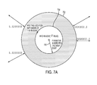
- FIG. 7A illustrates an RFID reader using a trilateration process to make a first read in which it detects an RFID tag within the reader's detection range. More specifically, RFID reader can determine a distance from the RFID reader to the detected tag, but does not yet know in which direction the RFID tag is located.
- the RFID reader is in a particular location, and directional arrow 700 represents a distance from the RFID reader to the RFID tag.
- circle 702 represents the RFID reader's detection range
- circle 704 represents a perimeter where the RFID tag might exist.
- the RFID tag is at the location shown on circle 704 , but the RFID reader does not yet have enough reads to know this location.
- the perimeter of circle 702 is the initial trigger zone of the RFID tag.
- the RFID reader's location may be determined using a wide variety of localization technologies, including GPS, Wi-Fi, cell tower signals and others.
- FIG. 7A also illustrates how probability scores may be determined and utilized.
- the trigger zone is defined, adjusted and tracked using probability and given a score.
- the region inside circle 704 is given a probability score of one (1).
- the probability score decreases. This decrease is shown by the four directional arrows marked by probability numbers that decrease (0.9 to 0.8 to 0.6 to 0.3 . . . 0.0) as one moves in any direction away from the center of circle 704 .
- the RFID reader has now moved to another location and makes a subsequent read. As shown, the RFID tag is in the same location, which is now outside the RFID reader's range, so the RFID tag is not detected.
- the RFID reader marks the region defined by directional arrow 708 and circle 706 as a region where the RFID tag does not exist. Thus, circle 706 defines a miss zone for the RFID tag.
- the RFID reader has now moved to another location and makes a subsequent read.
- the RFID tag is in the same location, which is now again within RFID reader's range, so the RFID tag is detected.
- the directional arrow 710 represents a distance from the current location of the RFID reader to the RFID tag.
- circle 712 represents another perimeter where the RFID tag might exist.
- the RFID tag is in fact at the location shown at one intersection of circle 712 with circle 704 , but the RFID reader does not yet have enough reads to know this location.
- the trigger zone has now evolved from the perimeter of circle 702 as shown in FIG. 7A to the circles 714 , 716 as shown in FIG. 7D .
- Circle 714 centers on one intersection between circles 712 and 704
- circle 716 centers on the other intersection between circles 712 and 704 .
- a radius 720 of circle 714 is preferably the maximum known detectable distance between the RFID reader and the RFID tag.
- a radius 722 of circle 716 is preferably the maximum known detectable distance between the RFID reader and the RFID tag.
- the RFID reader attached to a small and potentially wearable computing device continues to move around, ad hoc, and take additional reads. Using the trilateration process, with each additional read either the RFID tag is detected or it is not. If the RFID tag is not detected, additional miss zone data are determined, added to the list of previous miss zones and tracked. If the RFID tag is detected, additional trigger zone data is accumulated and the trigger zone, through additional trilateration iterations is continuously narrowed until the trilateration process converges to a potential localization.
- RFID tag may be moved at some point after its first read.
- RFID tag was at one location at 2:00 a.m., and then subsequently moved to a second location at 4:00 p.m.
- RFID reader makes an initial reading from a first location at 9:00 a.m., a second reading from a second location at 2:00 p.m., and a third reading from a third location at 5:00 p.m. Between the second and third RFID reader readings, RFID tag moved to its second location.
- the RFID reader At the third RFID reading at 5:00 p.m., the RFID reader reaches a potential localization conclusion that the RFID tag is currently at its 2:00 a.m. location, which is wrong. As shown in FIG. 8A , performing additional trilateration reads still might not resolve the problem.
- the present disclosure applies a targeted directional read process to supplement and verify the potential localization shown in FIG. 8A .
- the present disclosure utilizes a supplemental localization process applied to the narrowed trigger zone to either verify that the potential localization is correct, or determine that the potential localization is wrong.
- the supplemental localization actions in methodology 600 are represented by decision block 628 and block 630 .
- Directional read processes search for a tag by looking in a particular direction for the tag, then stepping through an incremental scan until the scan region is covered. The scan increments are typically small. For example, a directional read scan might begin its search at 0.0 degrees, then move to 0.1 degrees, then move to 0.2 degrees, and continue until the entire scan region is covered.
- technical benefits of the present disclosure include systems and methodologies for localizing movable ID tags during ad hoc, normal course movement of an ID reader attached to a relatively small and potentially wearable computing device.
- the present disclosure localizes objects attached to ID tags while a user is walking around an area (e.g., rooms of home) in the normal course without purposely positioning the ID reader.
- the disclosed object ID system utilizes a single reader that processes ID tag readings one at a time over a relatively long period of time. Even under such constraints, the disclosed systems and methodologies can localize ID tag that are moved either during localization or after localization has been verified.
- the present disclosure further provides a communications network through which multiple movable readers on the network can draw on the information accumulated in other movable readers on the same network when performing the above-described localization probability calculations, semi-detection process, potential localization process and verification process, thereby working both individually and jointly to identify, locate and track ID tags.
- a communications network through which multiple movable readers on the network can draw on the information accumulated in other movable readers on the same network when performing the above-described localization probability calculations, semi-detection process, potential localization process and verification process, thereby working both individually and jointly to identify, locate and track ID tags.
- Such a network can increase the validation frequency of object location for the object ID system, which is a concept similar to crowd sourcing.
- each block in the flowchart or block diagrams may represent a module, segment, or portion of instructions, which comprises one or more executable instructions for implementing the specified logical function(s).
- the functions noted in the block may occur out of the order noted in the figures.
- two blocks shown in succession may, in fact, be executed substantially concurrently, or the blocks may sometimes be executed in the reverse order, depending upon the functionality involved.
Abstract
Description
Claims (19)
Priority Applications (1)
| Application Number | Priority Date | Filing Date | Title |
|---|---|---|---|
| US14/500,096 US9436859B2 (en) | 2014-09-29 | 2014-09-29 | Ad hoc localization using a movable reader and movable id tags |
Applications Claiming Priority (1)
| Application Number | Priority Date | Filing Date | Title |
|---|---|---|---|
| US14/500,096 US9436859B2 (en) | 2014-09-29 | 2014-09-29 | Ad hoc localization using a movable reader and movable id tags |
Publications (2)
| Publication Number | Publication Date |
|---|---|
| US20160092708A1 US20160092708A1 (en) | 2016-03-31 |
| US9436859B2 true US9436859B2 (en) | 2016-09-06 |
Family
ID=55584774
Family Applications (1)
| Application Number | Title | Priority Date | Filing Date |
|---|---|---|---|
| US14/500,096 Active 2034-11-22 US9436859B2 (en) | 2014-09-29 | 2014-09-29 | Ad hoc localization using a movable reader and movable id tags |
Country Status (1)
| Country | Link |
|---|---|
| US (1) | US9436859B2 (en) |
Families Citing this family (6)
| Publication number | Priority date | Publication date | Assignee | Title |
|---|---|---|---|---|
| WO2018222824A1 (en) * | 2017-05-31 | 2018-12-06 | Hexagon Technology Center Gmbh | Method and apparatus for determining the location of a static object |
| DE102017209318A1 (en) * | 2017-06-01 | 2018-12-06 | Robert Bosch Gmbh | Method and device for localizing an object |
| US11120233B2 (en) * | 2018-04-09 | 2021-09-14 | Nec Corporation | Signature-based RFID localization |
| CN109388991B (en) * | 2018-09-21 | 2021-06-18 | 昆明理工大学 | Method for identifying RFID (radio frequency identification) tag by single reader by taking tail code continuous identification quantity as index |
| GB201919132D0 (en) * | 2019-12-23 | 2020-02-05 | E Track Ltd | Asset control system |
| DE102022202875A1 (en) * | 2022-03-24 | 2023-09-28 | Zf Friedrichshafen Ag | Recording of equipment of an emergency vehicle |
Citations (15)
| Publication number | Priority date | Publication date | Assignee | Title |
|---|---|---|---|---|
| US7044373B1 (en) * | 1998-08-14 | 2006-05-16 | 3M Innovative Properties Company | Radio frequency identification systems applications |
| US7260369B2 (en) * | 2005-08-03 | 2007-08-21 | Kamilo Feher | Location finder, tracker, communication and remote control system |
| US20070241904A1 (en) | 2006-03-28 | 2007-10-18 | Tomohiro Ozaki | RFID tag distance measuring system and reader |
| US20080042847A1 (en) * | 2006-08-14 | 2008-02-21 | Allen Hollister | Method for reading RFID tags using directional antennas |
| US7528721B2 (en) * | 2006-08-14 | 2009-05-05 | Eduard Levin | Identification and location of RF tagged articles |
| US7639138B2 (en) * | 2007-02-12 | 2009-12-29 | At&T Intellectual Property I, L.P. | Methods and apparatus to visualize locations of radio frequency identification (RFID) tagged items |
| US7782194B2 (en) * | 2007-03-25 | 2010-08-24 | Media Cart Holdings, Inc. | Cart coordinator/deployment manager |
| EP2395488A1 (en) | 2004-05-07 | 2011-12-14 | Sensormatic Electronics, LLC | Method of assigning and deducing the location of articles detected by multiple RFID antennae |
| WO2012044524A1 (en) | 2010-09-28 | 2012-04-05 | Symbol Technologies, Inc. | Method and reader device for identifying a location of a radio frequency identification (rfid) tag |
| US20130069985A1 (en) | 2011-09-21 | 2013-03-21 | Google Inc. | Wearable Computer with Superimposed Controls and Instructions for External Device |
| US8477013B2 (en) * | 2006-08-31 | 2013-07-02 | Sanjay Sarma | Method and system for performing mobile RFID asset detection and tracking |
| US20140074667A1 (en) * | 2012-09-11 | 2014-03-13 | Michael D. Smith | System and Method for Inventory Control of Mobile Assets |
| US8758102B2 (en) * | 2008-03-25 | 2014-06-24 | Wms Gaming, Inc. | Generating casino floor maps |
| US9020687B2 (en) * | 2005-04-12 | 2015-04-28 | Ehud Mendelson | System and method of obtaining and using a vehicle identifier for providing information to an end user |
| US9235823B2 (en) * | 2012-11-05 | 2016-01-12 | Bernsten International, Inc. | Underground asset management system |
-
2014
- 2014-09-29 US US14/500,096 patent/US9436859B2/en active Active
Patent Citations (15)
| Publication number | Priority date | Publication date | Assignee | Title |
|---|---|---|---|---|
| US7044373B1 (en) * | 1998-08-14 | 2006-05-16 | 3M Innovative Properties Company | Radio frequency identification systems applications |
| EP2395488A1 (en) | 2004-05-07 | 2011-12-14 | Sensormatic Electronics, LLC | Method of assigning and deducing the location of articles detected by multiple RFID antennae |
| US9020687B2 (en) * | 2005-04-12 | 2015-04-28 | Ehud Mendelson | System and method of obtaining and using a vehicle identifier for providing information to an end user |
| US7260369B2 (en) * | 2005-08-03 | 2007-08-21 | Kamilo Feher | Location finder, tracker, communication and remote control system |
| US20070241904A1 (en) | 2006-03-28 | 2007-10-18 | Tomohiro Ozaki | RFID tag distance measuring system and reader |
| US20080042847A1 (en) * | 2006-08-14 | 2008-02-21 | Allen Hollister | Method for reading RFID tags using directional antennas |
| US7528721B2 (en) * | 2006-08-14 | 2009-05-05 | Eduard Levin | Identification and location of RF tagged articles |
| US8477013B2 (en) * | 2006-08-31 | 2013-07-02 | Sanjay Sarma | Method and system for performing mobile RFID asset detection and tracking |
| US7639138B2 (en) * | 2007-02-12 | 2009-12-29 | At&T Intellectual Property I, L.P. | Methods and apparatus to visualize locations of radio frequency identification (RFID) tagged items |
| US7782194B2 (en) * | 2007-03-25 | 2010-08-24 | Media Cart Holdings, Inc. | Cart coordinator/deployment manager |
| US8758102B2 (en) * | 2008-03-25 | 2014-06-24 | Wms Gaming, Inc. | Generating casino floor maps |
| WO2012044524A1 (en) | 2010-09-28 | 2012-04-05 | Symbol Technologies, Inc. | Method and reader device for identifying a location of a radio frequency identification (rfid) tag |
| US20130069985A1 (en) | 2011-09-21 | 2013-03-21 | Google Inc. | Wearable Computer with Superimposed Controls and Instructions for External Device |
| US20140074667A1 (en) * | 2012-09-11 | 2014-03-13 | Michael D. Smith | System and Method for Inventory Control of Mobile Assets |
| US9235823B2 (en) * | 2012-11-05 | 2016-01-12 | Bernsten International, Inc. | Underground asset management system |
Non-Patent Citations (3)
| Title |
|---|
| A. Norman, et al., "Consumer Acceptance of RFID-Enabled Services in Validating Halal Status," IEEE, ISCIT 2009, pp. 911-915. |
| Cory Hekimian-Williams, et al., "Accurate Localization of RFID Tags Using Phase Difference", IEEE RFID 2010, Apr. 2010, pp. 89-96. |
| M. Bouet, et al., "RFID Tags: Positioning Principles and Localization Techniques," WD '08. 1st IFIP Wireless Days, IEEE, Nov. 24-27, 2008, pp. 1-5. |
Also Published As
| Publication number | Publication date |
|---|---|
| US20160092708A1 (en) | 2016-03-31 |
Similar Documents
| Publication | Publication Date | Title |
|---|---|---|
| US9436859B2 (en) | Ad hoc localization using a movable reader and movable id tags | |
| Brena et al. | Evolution of indoor positioning technologies: A survey | |
| He et al. | Wi-Fi fingerprint-based indoor positioning: Recent advances and comparisons | |
| Stojanović et al. | Indoor localization and tracking: Methods, technologies and research challenges | |
| Taneja et al. | Analysis of three indoor localization technologies for supporting operations and maintenance field tasks | |
| CN106461786B (en) | Indoor global positioning system | |
| US20150119086A1 (en) | Simultaneous localization and mapping systems and methods | |
| JP5299289B2 (en) | POSITION DETECTION DEVICE, POSITION DETECTION METHOD, AND POSITION DETECTION PROGRAM | |
| US9226114B2 (en) | Method and system of incorporating passive-based proximity data for position determination | |
| Scholz et al. | Resource-aware on-line RFID localization using proximity data | |
| KR20150061587A (en) | Method and system for automatically generating location signatures for positioning using inertial sensors | |
| Lee et al. | A location tracking system using ble beacon exploiting a double-gaussian filter | |
| JP5950330B2 (en) | LOCATION DEVICE, LOCATION SYSTEM, LOCATION METHOD, AND PROGRAM | |
| US10997474B2 (en) | Apparatus and method for person detection, tracking, and identification utilizing wireless signals and images | |
| Ali et al. | Systematic review of dynamic multi-object identification and localization: Techniques and technologies | |
| Jain et al. | A study on Indoor navigation techniques using smartphones | |
| KR20150130258A (en) | System and method fot locating wireless nodes | |
| Mostafa et al. | A survey of indoor localization systems in multi-floor environments | |
| Hu et al. | Could or could not of Grid-Loc: Grid BLE structure for indoor localisation system using machine learning | |
| De Schepper et al. | Dynamic BLE-based fingerprinting for location-aware smart homes | |
| CA3065025C (en) | Method and system of mobile device sequencing for localization | |
| Samu et al. | Survey on indoor localization: Evaluation performance of bluetooth low energy and fingerprinting based indoor localization system | |
| Werner et al. | Basic positioning techniques | |
| Chan et al. | Leveled indoor localization algorithms based on passive RFID | |
| Lin et al. | Accurate indoor navigation system using human-item spatial relation |
Legal Events
| Date | Code | Title | Description |
|---|---|---|---|
| AS | Assignment |
Owner name: INTERNATIONAL BUSINESS MACHINES CORPORATION, NEW Y Free format text: ASSIGNMENT OF ASSIGNORS INTEREST;ASSIGNORS:BURNS, ZACHARY A.;CHAN, YUK L.;CHOI, KIN K.;AND OTHERS;SIGNING DATES FROM 20140926 TO 20140929;REEL/FRAME:033841/0415 |
|
| AS | Assignment |
Owner name: GLOBALFOUNDRIES U.S. 2 LLC, NEW YORK Free format text: ASSIGNMENT OF ASSIGNORS INTEREST;ASSIGNOR:INTERNATIONAL BUSINESS MACHINES CORPORATION;REEL/FRAME:036550/0001 Effective date: 20150629 |
|
| AS | Assignment |
Owner name: GLOBALFOUNDRIES INC., CAYMAN ISLANDS Free format text: ASSIGNMENT OF ASSIGNORS INTEREST;ASSIGNORS:GLOBALFOUNDRIES U.S. 2 LLC;GLOBALFOUNDRIES U.S. INC.;REEL/FRAME:036779/0001 Effective date: 20150910 |
|
| FEPP | Fee payment procedure |
Free format text: PAYOR NUMBER ASSIGNED (ORIGINAL EVENT CODE: ASPN); ENTITY STATUS OF PATENT OWNER: LARGE ENTITY |
|
| STCF | Information on status: patent grant |
Free format text: PATENTED CASE |
|
| AS | Assignment |
Owner name: WILMINGTON TRUST, NATIONAL ASSOCIATION, DELAWARE Free format text: SECURITY AGREEMENT;ASSIGNOR:GLOBALFOUNDRIES INC.;REEL/FRAME:049490/0001 Effective date: 20181127 |
|
| MAFP | Maintenance fee payment |
Free format text: PAYMENT OF MAINTENANCE FEE, 4TH YEAR, LARGE ENTITY (ORIGINAL EVENT CODE: M1551); ENTITY STATUS OF PATENT OWNER: LARGE ENTITY Year of fee payment: 4 |
|
| AS | Assignment |
Owner name: GLOBALFOUNDRIES U.S. INC., CALIFORNIA Free format text: ASSIGNMENT OF ASSIGNORS INTEREST;ASSIGNOR:GLOBALFOUNDRIES INC.;REEL/FRAME:054633/0001 Effective date: 20201022 |
|
| AS | Assignment |
Owner name: GLOBALFOUNDRIES INC., CAYMAN ISLANDS Free format text: RELEASE BY SECURED PARTY;ASSIGNOR:WILMINGTON TRUST, NATIONAL ASSOCIATION;REEL/FRAME:054636/0001 Effective date: 20201117 |
|
| AS | Assignment |
Owner name: GLOBALFOUNDRIES U.S. INC., NEW YORK Free format text: RELEASE BY SECURED PARTY;ASSIGNOR:WILMINGTON TRUST, NATIONAL ASSOCIATION;REEL/FRAME:056987/0001 Effective date: 20201117 |
|
| MAFP | Maintenance fee payment |
Free format text: PAYMENT OF MAINTENANCE FEE, 8TH YEAR, LARGE ENTITY (ORIGINAL EVENT CODE: M1552); ENTITY STATUS OF PATENT OWNER: LARGE ENTITY Year of fee payment: 8 |