US9413463B2 - Apparatus and method for efficient two-way optical communication where transmitter may interfere with receiver - Google Patents
Apparatus and method for efficient two-way optical communication where transmitter may interfere with receiver Download PDFInfo
- Publication number
- US9413463B2 US9413463B2 US14/474,926 US201414474926A US9413463B2 US 9413463 B2 US9413463 B2 US 9413463B2 US 201414474926 A US201414474926 A US 201414474926A US 9413463 B2 US9413463 B2 US 9413463B2
- Authority
- US
- United States
- Prior art keywords
- optical
- transmit
- light pipe
- optical signal
- recited
- Prior art date
- Legal status (The legal status is an assumption and is not a legal conclusion. Google has not performed a legal analysis and makes no representation as to the accuracy of the status listed.)
- Active
Links
- 230000003287 optical effect Effects 0.000 title claims abstract description 140
- 238000004891 communication Methods 0.000 title claims abstract description 30
- 238000000034 method Methods 0.000 title claims description 27
- 238000005286 illumination Methods 0.000 claims description 19
- 238000005070 sampling Methods 0.000 claims description 15
- 230000004888 barrier function Effects 0.000 claims description 5
- 238000002329 infrared spectrum Methods 0.000 claims description 4
- 238000002211 ultraviolet spectrum Methods 0.000 claims description 4
- 238000001429 visible spectrum Methods 0.000 claims description 4
- 230000005540 biological transmission Effects 0.000 description 25
- 230000006870 function Effects 0.000 description 19
- 238000010586 diagram Methods 0.000 description 12
- 230000015654 memory Effects 0.000 description 11
- 239000000463 material Substances 0.000 description 6
- 230000008901 benefit Effects 0.000 description 5
- 230000007246 mechanism Effects 0.000 description 5
- 230000002688 persistence Effects 0.000 description 5
- 238000012545 processing Methods 0.000 description 5
- 230000000694 effects Effects 0.000 description 4
- 238000004519 manufacturing process Methods 0.000 description 4
- 239000002537 cosmetic Substances 0.000 description 3
- 238000011156 evaluation Methods 0.000 description 3
- 238000002955 isolation Methods 0.000 description 3
- 239000004033 plastic Substances 0.000 description 3
- 238000013459 approach Methods 0.000 description 2
- 230000004397 blinking Effects 0.000 description 2
- 238000013461 design Methods 0.000 description 2
- 238000011161 development Methods 0.000 description 2
- 230000000873 masking effect Effects 0.000 description 2
- 238000012986 modification Methods 0.000 description 2
- 230000004048 modification Effects 0.000 description 2
- 230000008569 process Effects 0.000 description 2
- 238000000926 separation method Methods 0.000 description 2
- 239000007787 solid Substances 0.000 description 2
- 241000282412 Homo Species 0.000 description 1
- 230000009471 action Effects 0.000 description 1
- 230000004075 alteration Effects 0.000 description 1
- 238000004883 computer application Methods 0.000 description 1
- 238000004590 computer program Methods 0.000 description 1
- 230000003247 decreasing effect Effects 0.000 description 1
- 239000006185 dispersion Substances 0.000 description 1
- 239000011152 fibreglass Substances 0.000 description 1
- 238000001914 filtration Methods 0.000 description 1
- 230000004927 fusion Effects 0.000 description 1
- 230000036039 immunity Effects 0.000 description 1
- 230000002452 interceptive effect Effects 0.000 description 1
- 238000012423 maintenance Methods 0.000 description 1
- 239000002184 metal Substances 0.000 description 1
- 238000010295 mobile communication Methods 0.000 description 1
- 239000013307 optical fiber Substances 0.000 description 1
- 239000003973 paint Substances 0.000 description 1
- 230000004044 response Effects 0.000 description 1
- 239000004065 semiconductor Substances 0.000 description 1
- 229910052710 silicon Inorganic materials 0.000 description 1
- 239000010703 silicon Substances 0.000 description 1
- 238000001228 spectrum Methods 0.000 description 1
- 239000000126 substance Substances 0.000 description 1
- 238000006467 substitution reaction Methods 0.000 description 1
Images


Classifications
-
- H—ELECTRICITY
- H04—ELECTRIC COMMUNICATION TECHNIQUE
- H04B—TRANSMISSION
- H04B10/00—Transmission systems employing electromagnetic waves other than radio-waves, e.g. infrared, visible or ultraviolet light, or employing corpuscular radiation, e.g. quantum communication
- H04B10/40—Transceivers
-
- H—ELECTRICITY
- H04—ELECTRIC COMMUNICATION TECHNIQUE
- H04B—TRANSMISSION
- H04B10/00—Transmission systems employing electromagnetic waves other than radio-waves, e.g. infrared, visible or ultraviolet light, or employing corpuscular radiation, e.g. quantum communication
- H04B10/11—Arrangements specific to free-space transmission, i.e. transmission through air or vacuum
- H04B10/114—Indoor or close-range type systems
- H04B10/1143—Bidirectional transmission
-
- H—ELECTRICITY
- H04—ELECTRIC COMMUNICATION TECHNIQUE
- H04B—TRANSMISSION
- H04B10/00—Transmission systems employing electromagnetic waves other than radio-waves, e.g. infrared, visible or ultraviolet light, or employing corpuscular radiation, e.g. quantum communication
- H04B10/11—Arrangements specific to free-space transmission, i.e. transmission through air or vacuum
- H04B10/114—Indoor or close-range type systems
- H04B10/116—Visible light communication
-
- H04B10/2504—
-
- H—ELECTRICITY
- H04—ELECTRIC COMMUNICATION TECHNIQUE
- H04B—TRANSMISSION
- H04B10/00—Transmission systems employing electromagnetic waves other than radio-waves, e.g. infrared, visible or ultraviolet light, or employing corpuscular radiation, e.g. quantum communication
- H04B10/25—Arrangements specific to fibre transmission
- H04B10/2507—Arrangements specific to fibre transmission for the reduction or elimination of distortion or dispersion
-
- H—ELECTRICITY
- H04—ELECTRIC COMMUNICATION TECHNIQUE
- H04B—TRANSMISSION
- H04B10/00—Transmission systems employing electromagnetic waves other than radio-waves, e.g. infrared, visible or ultraviolet light, or employing corpuscular radiation, e.g. quantum communication
- H04B10/25—Arrangements specific to fibre transmission
- H04B10/2589—Bidirectional transmission
- H04B10/25891—Transmission components
-
- H—ELECTRICITY
- H04—ELECTRIC COMMUNICATION TECHNIQUE
- H04B—TRANSMISSION
- H04B10/00—Transmission systems employing electromagnetic waves other than radio-waves, e.g. infrared, visible or ultraviolet light, or employing corpuscular radiation, e.g. quantum communication
- H04B10/50—Transmitters
- H04B10/501—Structural aspects
- H04B10/502—LED transmitters
Definitions
- This invention relates in general to the field of electronic devices, and more particularly to an apparatus and method that provides for efficient two-way optical communication where an optical transmitter may interfere with a corresponding optical receiver.
- LEDs light emitting diodes
- light pipes also referred to as “light tunnels” or “light tubes”
- light pipes have been developed to enable the light from one or more LEDs mounted on a circuit board in a device to be transported efficiently to an area of a display where the light is required, thus eliminating a significant amount of hand labor that would otherwise be required to fabricate a product.
- light pipes are generally manufactured from plastic materials that transport light via a reflective lining, or transparent solids that transport the light by total internal reflection. As such, the pipes, according to configuration, are snapped into place on a circuit board, and the board is mounted behind a panel or display.
- light pipes are used to receive light transmitted from outside of the given device and to route the light to light sensors internal to the given device.
- Such an application can be as simple as sensing ambient light in order to control brightness of a display, or it may be more complex, such as receiving an optical commissioning data stream from another device in order to configure the given device for operation.
- transmit circuits and receive circuits be of such disparate optical wavelengths that transmissions from the transmit circuits are essentially undetectable by the receive circuits. But this approach is not very practical in consumer devices that employ inexpensive optical sensors (e.g., photodiodes) that sense over a broad optical spectrum.
- an apparatus provides for two-way optical communication.
- the apparatus includes a transmit element, a receive element, and a transceive processor.
- the transmit element is coupled to a light pipe, and is configured to transmit a first optical signal through the light pipe.
- the receive element is also coupled to the light pipe, and is configured to receive a second optical signal through the light pipe.
- the transceive processor is coupled to the transmit and receive elements, and is configured to direct the transmit element to pause and then resume transmitting the first optical signal during first intervals, and is configured to direct the receive element to sample for the second optical signal during one or more second intervals within each of the first intervals, where the each of the first intervals is less than a first value and the first intervals occur at a duty cycle no greater than a second value, and where the first and second values are controlled by the transceive processor such that a user perceives the first optical signal as having a constant state for a third interval.
- the apparatus has a light pipe, a transmit element, a receive element, and a transceive processor.
- the light pipe is configured to transport illumination from optical signals between ends of the light pipe.
- the transmit element is coupled to a first one or the ends, and is configured to transmit a first optical signal through the light pipe to a second one of the ends.
- the receive element is coupled to the light pipe, and is configured to receive a second optical signal transported through the light pipe from the second one of the ends.
- the transceive processor is coupled to the transmit and receive elements, and is configured to direct the transmit element to pause and then resume transmitting the first optical signal during first intervals, and is configured to direct the receive element to sample for the second optical signal during one or more second intervals within each of the first intervals, where the each of the first intervals is less than a first value and the first intervals occur at a duty cycle no greater than a second value, and where the first and second values are controlled by the transceive processor such that a user perceives the first optical signal as having a constant state for a third interval.
- Another aspect of the present invention comprehends a method for providing two-way optical communication in a shared light pipe.
- the method includes: via a transmit element, transmitting a first optical signal through the shared light pipe; pausing and then resuming the transmitting during first intervals, where each of the first intervals is less than a first value and the first intervals occur at a duty cycle no greater than a second value, and where the first and second values are controlled by a transceive processor such that a user perceives the first optical signal as having a constant state for a third interval; and via a receive element, receiving a second optical signal through the shared light pipe during one or more second intervals within each of the first intervals.
- FIG. 1 is a diagram illustrating a frontal view of an electronic device according to the present invention
- FIG. 2 is a cutaway view of an embodiment the electronic device of FIG. 1 taken along axis A-A;
- FIG. 3 is a cutaway view of an alternative embodiment the electronic device of FIG. 1 taken along axis A-A;
- FIG. 4 is a timing diagram showing an optical communication multiplexing technique according to the present invention.
- FIG. 5 is a flow diagram illustrating a method according to the present invention for full duplex optical communication via a shared light pipe.
- Integrated Circuit A set of electronic circuits fabricated on a small piece of semiconductor material, typically silicon.
- An IC is also referred to as a chip, a microchip, or a die.
- CPU Central Processing Unit
- the electronic circuits i.e., “hardware” that execute the instructions of a computer program (also known as a “computer application” or “application”) by performing operations on data that include arithmetic operations, logical operations, and input/output operations.
- a computer program also known as a “computer application” or “application”
- Microprocessor An electronic device that functions as a CPU on a single integrated circuit.
- a microprocessor receives digital data as input, processes the data according to instructions fetched from a memory (either on-die or off-die), and generates results of operations prescribed by the instructions as output.
- a general purpose microprocessor may be employed in a desktop, mobile, or tablet computer, and is employed for uses such as computation, text editing, multimedia display, and Internet browsing.
- a microprocessor may also be disposed in an embedded system to control a wide variety of devices including appliances, mobile telephones, smart phones, and industrial control devices.
- FIG. 1 a diagram is presented illustrating a frontal view of an electronic device 100 according to the present invention.
- a device 100 may be found in virtually every household and business configured as a personal item (e.g., an appliance, an entertainment device, a cell phone, or tablet computer) or as a device disposed in a transportation vehicle (e.g., automobile, train, airplane, ship, etc.) in which it is required to provide for full duplex optical communication with a user, another device, or a user and another device, where the electromagnetic frequency range for optical communication may include the visible, ultraviolet, and infrared spectrums.
- a personal item e.g., an appliance, an entertainment device, a cell phone, or tablet computer
- a transportation vehicle e.g., automobile, train, airplane, ship, etc.
- the electromagnetic frequency range for optical communication may include the visible, ultraviolet, and infrared spectrums.
- the device 100 may include a housing 102 for enclosing electromechanical components (not shown) therein.
- a desirable configuration for providing optical communication via the device 100 may include use of a light pipe 101 that projects through a correspondingly shaped interstice in the housing 102 .
- the light pipe 101 may be covered by a translucent lens or cover (not shown) to provide for filtering, shading, dispersion, etc.
- the information transmitted optically via the light pipe may be merely illumination to provide an optically suitable environment for performing other activities.
- the information transmitted may be indication of the state of the device 100 (e.g., on, off, powering up, message waiting, etc.) or may comprise optically encoded data that is transmitted to a user or to another device (e.g., configuration information, commissioning information, control commands and responses, etc.).
- the device 100 may comprise a plurality of light pipes 101 of various optical frequencies in accordance with functions of the device 100 , however, for simplicity sake within the present application, illustration of a single light pipe 101 will suffice.
- the light pipe 101 may be rigid or flexible, as is appreciated by those in the art, and may comprise smooth hollow structures, generally fabricated from plastic materials, that contain light with a reflective lining, or transparent solids that contain the light by total internal reflection.
- Light pipes such as the pipe 101 of FIG. 1 , are commonly used in an electronic device 100 to direct illumination from light sources (e.g., light emitting diodes (LEDs)) mounted on a circuit board to indicators and/or backlit controls (e.g., buttons, switches, dials, etc.).
- Light pipes 101 facilitate cost-effective fabrication of the device 100 by enabling all light sources to be mounted on a single circuit board, where light from each of the light sources may be directed up and away from the board to where illumination is required.
- Light pipes 101 may be purchased in a variety of configurations that may include tens of light pipes 101 fabricated together in a single module.
- a light pipe 101 is for reception of optically transmitted data.
- light is directed from outside of the housing 102 through the light pipe 101 to optical reception circuits (e.g., photodiodes, phototransistors, etc.) (not shown) disposed within the housing 102 .
- the optical reception circuits may be employed to sense ambient optical conditions around the device 100 , or they may be employed to receive optically encoded information (e.g., commissioning data, maintenance data, control data, etc.) that is transmitted by another device.
- the cost of an electronic device 100 that employs light pipes 101 may be markedly less than other forms of manufacture since costly hand labor is not generally required to mount multiple light sources on a single circuit board along with a single rigid light tube that is employed to transport the multiple light sources to a display that is removed from the circuit board by several inches.
- the constraints that illumination/state conditions be visibly recognizable to a user may preclude use of the light pipe 101 for two-way communications because the light source is required to be continuously on or it must be on for relatively long periods of time (e.g., 500 milliseconds) from a communications perspective.
- This limitation is thus disadvantageous for many types of emerging consumer devices.
- Another limitation associated with use of a shared light pipe 101 arises as a result of unintended interference resulting from transmitted light reflections into a receiving sensor that shares the light pipe 101 with a transmitting element.
- the present invention overcomes the above noted limitations, and others, by providing a shared light pipe mechanism that allows for full duplex optical communication under conditions in which it is required to provide constant illumination and/or visibly recognizable state indication.
- a shared light pipe 101 may be employed to transmit a constant illumination or visibly recognizable state indication, as perceived by the human eye, while simultaneously allowing for windows of receptive optical sampling during reception periods less than a human flicker fusion threshold.
- the present inventors have determined that these reception periods should be roughly no greater than 40 milliseconds and should occur at an approximately 10 percent duty cycle.
- one or more reception periods of roughly no greater than 40 milliseconds may be scheduled at a maximum of an approximately 10 percent duty cycle. For example, if the device 100 has a transmission period of 500 milliseconds, according to the present invention, five 10-millisecond reception periods may be opened every 100 milliseconds.
- optical communication may occur between two devices or two devices and a user.
- the present invention lends itself well to consumer electronics devices that include a light pipe 101 comprising an optical transmitter (i.e., a light source such as, but not limited to, an LED) and optical receiver (i.e., a light sensor such as, but not limited to, a photodiode, photoresistor, or phototransistor) that are located in proximity such that the optical properties of a corresponding light pipe cause a reflection of the transmitter's data into the receiver.
- an optical transmitter i.e., a light source such as, but not limited to, an LED
- optical receiver i.e., a light sensor such as, but not limited to, a photodiode, photoresistor, or phototransistor
- the device 100 may include a housing 202 having a light pipe 201 of the well known Y configuration that is disposed through a corresponding interstice in the housing 202 .
- the light pipe 201 may be configured as is described above having an internal reflective surface 205 that allows for transmission of light from an optical transmitter 212 to outside of the housing 202 and for reception of light from outside the housing 202 into an optical receiver 214 .
- the device 100 may further include an optical barrier 204 embodied as black tape or paint as shown in FIG. 2 to optically isolate transmit and receive paths within the light pipe 201 by minimizing unintended reflections from the transmitter 212 into the receiver 214 .
- the device 100 may further comprise a transceive processor 211 that is coupled to the transmitter 212 via bus 213 and to the receiver 214 via bus 215 .
- the transmitter 212 may be disposed as a light source such as, but not limited to, an LED that receives a voltage or current via bus 213 and responsively emits light in a wavelength within the optical frequency range as noted above.
- the receiver 214 may be disposed as a light sensor such as, but not limited to, a photodiode or phototransistor that receives light via the light pipe 201 and that converts the light into a corresponding voltage or current, which is provided to the transceive processor 211 via bus 215 .
- the transmitter 212 is employed generally for communication with a human eye (not shown) that exploits the persistence of vision effect.
- the transceive processor 211 directs the transmitter 212 via bus 213 to turn off for one or more reception periods that are imperceptible to the eye, as is described above, and during the one or more reception periods the transceive processor 211 samples the output of the receiver 214 via bus 215 . Accordingly, incoming optical data may be sampled while still providing for a perceived constant illumination or visibly recognizable state indication.
- the present inventors note that the perceived constant illumination/state indication may also be employed as part of a modulated transmission from the device 100 to the human eye.
- a 500 millisecond transmission interval time followed by a 500 millisecond period when the transmitter 212 is off may be used to indicate a status message to a the human eye.
- the receiver 215 may be sampled by the transceive processor 211 during the 500 millisecond period when the transmitter 212 is off, and also during the 500 millisecond transmission period, but during the 500 millisecond transmission period, one or more reception periods as described above are controlled by the transceive processor 211 to continue to allow for sampling of incoming optical data.
- the transceive processor 211 may schedule 1-millisecond reception periods every 10 milliseconds during transmission intervals, though the present inventors note that desired values for the reception interval and duty cycle may be established via programming in closed loop fashion, or they may be fixed based on the characteristics of the transmitter 212 , the receiver 214 , and intended functions of the device 100 .
- the device 100 may be employed to transmit and receive optical data to/from a corresponding optical device (not shown) rather than to the human eye, where the bit rate of the transmitted data is substantially higher than the bit rate of the data transmitted by the corresponding optical device. Accordingly, while scheduling reception periods as described above within the device 100 for sampling of the receiver 214 during transmission intervals, the corresponding optical device may sample for data that is transmitted by the device 100 without unacceptable sampling errors since the bit rate of data transmitted by the device 100 is substantially higher. In one embodiment, the transmitted bit rate of the device 100 is at least 10 times that of the corresponding optical device.
- reception intervals and associated duty cycles may be dynamically changed by the transceive processor 211 according to ambient light level of the environment around the device 100 .
- an analog light intensity reading may also be taken by components within the receiver 214 .
- the device 100 may sense ambient light level of the surrounding environment and, as a result of changing ambient light level, the transceive processor 211 may employ the analog intensity value to adjust the reception intervals and duty cycles as a function of the surrounding environment, thus enabling the device 100 to decrease/increase perceived brightness of the transmitted light and achieve a balanced cosmetic appearance to users in both direct sunlight and darkened rooms.
- reception intervals and duty cycles may be employed to mask undesirable mechanical structures within the device 100 along with cast shadows of metallic, fiberglass, and/or plastic internal components within the device 100 , which would otherwise be particularly noticeable when the device 100 is utilized in a dark room.
- the present inventors also note that adjusting the reception intervals and duty cycles not only provides cosmetic and aesthetic benefits, but also energy savings, and ambient optical noise immunity when required.
- the transceive processor 211 is configured to perform the functions and operations as discussed above.
- the transceive processor 211 comprises logic, circuits, devices, or microcode (i.e., micro instructions or native instructions), or a combination of logic, circuits, devices, or microcode, or equivalent elements that are employed to execute the functions and operations according to the present invention as noted.
- the elements employed to accomplish these operations and functions within the transceive processor 211 may be shared with other circuits, microcode, etc., that are employed to perform other functions and/or operations within the transceive processor 211 .
- microcode is a term employed to refer to a plurality of micro instructions.
- a micro instruction (also referred to as a native instruction) is an instruction at the level that a unit executes.
- micro instructions are directly executed by a reduced instruction set computer (RISC) microprocessor.
- RISC reduced instruction set computer
- CISC complex instruction set computer
- complex instructions are translated into associated micro instructions, and the associated micro instructions are directly executed by a unit or units within the CISC microprocessor.
- the transceive processor 211 may comprise a microprocessor or other central processing unit (CPU) that executes one or more application programs disposed in a memory (not shown) to perform the transmission and reception functions described above.
- the memory may be either internal or external to the CPU.
- the transceive processor 211 may further comprise additional electronic circuits (e.g., digital-to-analog converters, analog-to-digital converters) configured to couple the microprocessor/CPU to the transmitter 212 and receiver 214 via respective busses 213 , 215 .
- FIG. 3 a diagram 300 is presented of a cutaway view of an alternative embodiment the electronic device 100 of FIG. 1 taken along axis A-A.
- the device 100 may include a housing 302 having a light pipe 301 that is disposed through a corresponding interstice in the housing 302 .
- the light pipe 301 may be configured as is described above having an internal reflective surface 305 that allows for transmission/reception of light from/to an optical transceiver 321 that may be employed to transmit and receive optical signals.
- the device 100 may further comprise a transceive processor 311 that is coupled to the transceiver 321 .
- the transceiver 321 may comprise a combined light source and light sensor, as these elements are described with reference to FIG. 2 , disposed in relative proximity to the light pipe 301 .
- the transceiver 321 may comprise a separate light source and light sensor, with no optical barrier in between them.
- the source and sensor share the same internal reflective surface 305 within the light pipe 301 rather than being configured as a Y.
- optical transmit and receive elements within the transceiver 321 function substantially as like elements are described above with reference to FIG. 2 , except that the transmit and receive elements within the transceiver 321 share the same reflective surface 305 within the pipe. Consequently, it is impractical to employ masking material to minimize unintended reflections from transmit element to receive element.
- the technique according to the present invention employs the persistence of vision effect, two-way communication is enabled at the device 100 to a user and from another device, or between the device 100 and another device, as is described above.
- the transceive processor 311 directs the transmit element within the transceiver 321 to turn off for one or more reception periods that are imperceptible to the eye, as is described above, and during the one or more reception periods the transceive processor 321 samples the output of the receive element within the transceiver 321 . Accordingly, incoming optical data may be sampled while still providing for a perceived constant illumination or visibly recognizable state indication. In addition, the perceived constant illumination/state indication may also be employed as part of a modulated transmission from the device 100 to the human eye.
- a 500 millisecond transmission interval time followed by a 500 millisecond period when the transmit element is off may be used to indicate a status message to a the human eye.
- the receive element may be sampled by the transceive processor 321 during the 500 millisecond period when the transmit element is off, and also during the 500 millisecond transmission period, but during the 500 millisecond transmission period, one or more reception periods as described above are controlled by the transceive processor 311 to continue to allow for sampling of incoming optical data.
- the transceive processor 311 may schedule 1-millisecond reception periods every 10 milliseconds during transmission intervals, though the present inventors note that desired values for the reception interval and duty cycle may be established via programming in closed loop fashion, or they may be fixed based on the characteristics of the transceiver 321 , and intended functions of the device 100 .
- the device 100 may be employed to transmit and receive optical data to/from a corresponding optical device (not shown) rather than to the human eye, where the bit rate of the transmitted data is substantially higher than the bit rate of the data transmitted by the corresponding optical device. Accordingly, while scheduling reception periods as described above within the device 100 for sampling of the receiver element during transmission intervals, the corresponding optical device may sample for data that is transmitted by the device 100 without unacceptable sampling errors since the bit rate of data transmitted by the device 100 is substantially higher. In one embodiment, the transmitted bit rate of the device 100 is at least 10 times that of the corresponding optical device.
- reception intervals and associated duty cycles may be dynamically changed by the transceive processor 311 according to ambient light level of the environment around the device 100 .
- an analog light intensity reading may also be taken by components within the transceiver 321 .
- the device 100 may sense ambient light level of the surrounding environment and, as a result of changing ambient light level, the transceive processor 311 may employ the analog intensity value to adjust the reception intervals and duty cycles as a function of the surrounding environment, thus enabling the device 100 to decrease/increase perceived brightness of the transmitted light and achieve a balanced cosmetic appearance to users in both direct sunlight and darkened rooms.
- the transceive processor 311 is configured to perform the functions and operations as discussed above.
- the transceive processor 311 comprises logic, circuits, devices, or microcode (i.e., micro instructions or native instructions), or a combination of logic, circuits, devices, or microcode, or equivalent elements that are employed to execute the functions and operations according to the present invention as noted.
- the elements employed to accomplish these operations and functions within the transceive processor 311 may be shared with other circuits, microcode, etc., that are employed to perform other functions and/or operations within the transceive processor 311 .
- microcode is a term employed to refer to a plurality of micro instructions.
- a micro instruction (also referred to as a native instruction) is an instruction at the level that a unit executes.
- micro instructions are directly executed by a reduced instruction set computer (RISC) microprocessor.
- RISC reduced instruction set computer
- CISC complex instruction set computer
- complex instructions are translated into associated micro instructions, and the associated micro instructions are directly executed by a unit or units within the CISC microprocessor.
- the transceive processor 311 may comprise a microprocessor or other central processing unit (CPU) that executes one or more application programs disposed in a memory (not shown) to perform the transmission and reception functions described above.
- the memory may be either internal or external to the CPU.
- the transceive processor 311 may further comprise additional electronic circuits (e.g., digital-to-analog converters, analog-to-digital converters) configured to couple the microprocessor/CPU to the transceiver 321 .
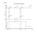
- FIG. 4 a timing diagram 400 is presented showing an optical communication multiplexing technique according to the present invention.
- the diagram 400 depicts a transmit signal 401 , such as may be provided by the transceive processor 211 , 311 of FIGS. 2-3 to direct the transmitter 212 or transmit element within the transceiver 321 to transmit light into the light pipe 201 , 301 .
- the diagram 400 also shows a receive signal 403 , such as may be provided by the transceive processor 211 , to direct the receiver 214 or receive element within the transceiver 321 to sample light received into the light pipe 201 , 301 from another device.
- the diagram 400 further includes an incoming optical signal 405 , such as may be transmitted by another device into the light pipe 201 , 301 .
- the diagram 400 depicts a scenario where the light source of the device 100 is to be perceived by the user as being illuminated, that is, a scenario where the transmission interval is greater than the time depicted in the diagram 400 .
- the transceive processor 211 , 311 controls the states of the transmit and receive signals 401 , 403 according to configuration of the reception intervals and duty cycles within the transceive processor 211 , 311 .
- Reception periods 402 , 404 occur between times T 1 and T 2 , and between times T 3 and T 4 , where the transmit signal is in an off state and the receive signal is in an open state.
- the present inventors note that the period that the transmit signal 401 is in an off state indicates the reception interval and the period between off states of the transmit signal 401 indicates the duty cycle.
- the receive signal 403 is shown in an open period 404 approximately equal to the period when the transmit signal 401 is off, the present invention allows for a plurality of open periods 404 within the reception interval 402 to provide for sampling of the incoming signal 405 .
- a flow diagram 500 is presented illustrating a method according to the present invention for full duplex optical communication via a shared light pipe, such as the light pipe 201 , 301 of FIGS. 2-3 .
- Flow begins at block 501 , where a device 100 according to the present invention is operating to communicate illumination or state condition to a user. Flow then proceeds to decision block 502 .
- an evaluation is made to determine if a transmitter within the device 100 is required to be perceived by the user as being on. If not, then flow proceeds to block 503 . If so, then flow proceeds to block 504 .
- one or more receive windows are allowed to be opened to sample for incoming optical data received by the light pipe 201 , 301 . Flow then proceeds to decision block 502 .
- a receive window if open, is closed, and the transmitter is set to an on state to provide light through the light pipe 201 , 301 . Flow then proceeds to block 505 .
- a transmitter on state timer is initiated.
- the on state timer is approximately 90 percent of the duty cycle corresponding to a reception interval for the device 100 . Flow then proceeds to decision block 506 .
- an evaluation is made to determine if the on state timer has timed out. If not, then flow proceeds to decision block 506 .
- the transmitter remains in an on state and no receive sampling is allowed.
- the transmitter is set to an off state, ceasing illumination, and one or more receive windows may be opened according to device function in order to sample incoming optical signals. Flow then proceeds to block 508 .
- a transmitter off state timer is initiated.
- the value of the off state timer defines the reception interval for the device 100 , and the value of the off state timer divided by the sum of the off state and on state timers determines the duty cycle for the device. Flow then proceeds to block 509 .
- incoming light is sampled from the light pipe 201 , 301 during one or more receive windows that occur during the reception interval defined by the off state timer. During the one or more receive windows, the incoming light may be sampled one or more times. Flow then proceeds to decision block 510 .
- an evaluation is made to determine if the off state timer has timed out, thus ending the reception interval. If not, then flow proceeds to block 509 . If so, then flow proceeds to block 502 .
- the method continues until such time as the device 100 is placed in an inoperative state or turned off.
- the transceive processor 211 , 311 may be configured such that high bit rate data may be transmitted during the periods outside of when receive sampling windows are open ( 404 in FIG. 4 ) at a rate imperceptible to the human eye such that the light source is perceived to be either on or off for these periods, as is appropriate for indicated function.
- the device 100 transmits optical data at a bit rate that is substantially faster than the bit rate which it samples during the reception intervals.
- a data encoding scheme may be employed to allow for transmit waveforms from the device 100 where short duration transmitter off periods are not construed by a receiving device as being off, that is, interpreted as a logical zero.
- the device 100 may transmit optical data at a bit rate that is substantially slower than the receiving device's bit rate which is sampled by the device 100 .
- the software implemented aspects of the invention are typically encoded on some form of program storage medium or implemented over some type of transmission medium.
- the program storage medium may be electronic (e.g., read only memory, flash read only memory, electrically programmable read only memory), random access memory magnetic (e.g., a floppy disk or a hard drive) or optical (e.g., a compact disk read only memory, or “CD ROM”), and may be read only or random access.
- the transmission medium may be metal traces, twisted wire pairs, coaxial cable, optical fiber, or some other suitable transmission medium known to the art. The invention is not limited by these aspects of any given implementation.
Abstract
Description
| SERIAL | FILING | |
| NUMBER | DATE | TITLE |
| 61/872,330 | Aug. 30, 2013 | APPARATUS AND METHOD FOR |
| (RVLV.0107) | EFFICIENT TWO-WAY OPTICAL | |
| COMMUNICATION WHERE | ||
| TRANSMITTER MAY INTERFERE | ||
| WITH RECEIVER | ||
| 61/918,716 | Dec. 20, 2013 | APPARATUS AND METHOD FOR |
| (RVLV.0109) | EFFICIENT TWO-WAY OPTICAL | |
| COMMUNICATION WHERE | ||
| TRANSMITTER MAY INTERFERE | ||
| WITH RECEIVER | ||
Claims (21)
Priority Applications (2)
| Application Number | Priority Date | Filing Date | Title |
|---|---|---|---|
| US14/474,926 US9413463B2 (en) | 2013-08-30 | 2014-09-02 | Apparatus and method for efficient two-way optical communication where transmitter may interfere with receiver |
| US15/231,541 US9712244B2 (en) | 2013-08-30 | 2016-08-08 | Apparatus and method for efficient two-way optical communication where transmitter may interfere with receiver |
Applications Claiming Priority (3)
| Application Number | Priority Date | Filing Date | Title |
|---|---|---|---|
| US201361872330P | 2013-08-30 | 2013-08-30 | |
| US201361918716P | 2013-12-20 | 2013-12-20 | |
| US14/474,926 US9413463B2 (en) | 2013-08-30 | 2014-09-02 | Apparatus and method for efficient two-way optical communication where transmitter may interfere with receiver |
Related Child Applications (1)
| Application Number | Title | Priority Date | Filing Date |
|---|---|---|---|
| US15/231,541 Continuation US9712244B2 (en) | 2013-08-30 | 2016-08-08 | Apparatus and method for efficient two-way optical communication where transmitter may interfere with receiver |
Publications (2)
| Publication Number | Publication Date |
|---|---|
| US20150063821A1 US20150063821A1 (en) | 2015-03-05 |
| US9413463B2 true US9413463B2 (en) | 2016-08-09 |
Family
ID=52583427
Family Applications (2)
| Application Number | Title | Priority Date | Filing Date |
|---|---|---|---|
| US14/474,926 Active US9413463B2 (en) | 2013-08-30 | 2014-09-02 | Apparatus and method for efficient two-way optical communication where transmitter may interfere with receiver |
| US15/231,541 Active US9712244B2 (en) | 2013-08-30 | 2016-08-08 | Apparatus and method for efficient two-way optical communication where transmitter may interfere with receiver |
Family Applications After (1)
| Application Number | Title | Priority Date | Filing Date |
|---|---|---|---|
| US15/231,541 Active US9712244B2 (en) | 2013-08-30 | 2016-08-08 | Apparatus and method for efficient two-way optical communication where transmitter may interfere with receiver |
Country Status (1)
| Country | Link |
|---|---|
| US (2) | US9413463B2 (en) |
Families Citing this family (11)
| Publication number | Priority date | Publication date | Assignee | Title |
|---|---|---|---|---|
| US7833527B2 (en) | 2006-10-02 | 2010-11-16 | Amgen Inc. | Methods of treating psoriasis using IL-17 Receptor A antibodies |
| TW201117824A (en) | 2009-10-12 | 2011-06-01 | Amgen Inc | Use of IL-17 receptor a antigen binding proteins |
| WO2013016220A1 (en) | 2011-07-22 | 2013-01-31 | Amgen Inc. | Il-17 receptor a is required for il-17c biology |
| US9496955B2 (en) * | 2013-09-19 | 2016-11-15 | eocys, LLC | Devices and methods to produce and receive an encoded light signature |
| KR20160130248A (en) | 2014-03-31 | 2016-11-10 | 키린-암젠, 인코포레이티드 | Methods of treating nail and scalp psoriasis |
| US10282978B2 (en) | 2015-10-28 | 2019-05-07 | Abl Ip Holding, Llc | Visible light programming of daylight sensors and other lighting control devices |
| US9591212B1 (en) | 2015-10-30 | 2017-03-07 | Essential Products, Inc. | System and method for reducing the number of ports associated with a mobile device |
| US9762712B2 (en) * | 2015-10-30 | 2017-09-12 | Essential Products, Inc. | System and method for reducing the number of ports associated with a mobile device |
| EP3948750A4 (en) * | 2018-02-06 | 2022-11-16 | Wickersham, Jill Anne | Systems and methods for real-time item identification and sourcing |
| WO2020162935A1 (en) * | 2019-02-06 | 2020-08-13 | Wickersham Jill Anne | Systems and methods for real-time item identification and sourcing |
| US11364456B2 (en) | 2019-03-01 | 2022-06-21 | Brita Lp | Container assembly |
Citations (57)
| Publication number | Priority date | Publication date | Assignee | Title |
|---|---|---|---|---|
| US20020016639A1 (en) | 1996-10-01 | 2002-02-07 | Intelihome, Inc., Texas Corporation | Method and apparatus for improved building automation |
| US20030061284A1 (en) | 2001-09-26 | 2003-03-27 | Angelo Mandarino | Methods, systems and computer program products for conducting a virtual product presentation |
| US20030169728A1 (en) | 2002-03-11 | 2003-09-11 | Samsung Electronics Co., Ltd. | Apparatus for controlling devices in a sub-network of a home-network and a method thereof |
| US20060174102A1 (en) | 2005-01-28 | 2006-08-03 | Control4 Corporation | Method and apparatus for device detection and multi-mode security in a control network |
| US20060259183A1 (en) | 2003-11-04 | 2006-11-16 | Universal Electronics Inc. | System and methods for home appliance identification and control in a networked environment |
| US20080037444A1 (en) | 2006-08-08 | 2008-02-14 | Marvell Semiconductor, Inc. | Ad-hoc simple configuration |
| US7352930B2 (en) | 2005-07-25 | 2008-04-01 | Research In Motion Limited | Shared light pipe for a message indicator and light sensor |
| US20080089300A1 (en) | 2006-09-18 | 2008-04-17 | Marvell International Ltd. | Establishment of ad-hoc networks between multiple devices |
| US20080122606A1 (en) * | 2006-04-17 | 2008-05-29 | James Roy Bradley | System and Method for Vehicular Communications |
| US20080219672A1 (en) * | 2007-03-09 | 2008-09-11 | John Tam | Integrated infrared receiver and emitter for multiple functionalities |
| US20090080896A1 (en) | 2007-09-25 | 2009-03-26 | Pereira Luis R | Commissioning tool, commissioning system and method of commissioning a number of wireless nodes |
| US20090244097A1 (en) | 2008-03-25 | 2009-10-01 | Leonardo William Estevez | System and Method for Providing Augmented Reality |
| US20100141153A1 (en) | 2006-03-28 | 2010-06-10 | Recker Michael V | Wireless lighting devices and applications |
| US20100192212A1 (en) | 2009-01-28 | 2010-07-29 | Gregory G. Raleigh | Automated device provisioning and activation |
| US7830258B2 (en) | 2005-08-19 | 2010-11-09 | Adasa, Inc. | Systems, methods, and devices for converting and commissioning wireless sensors |
| US20100283584A1 (en) | 2005-08-19 | 2010-11-11 | Mcallister Clarke William | Systems, Methods, and Devices for Commissioning Wireless Sensors. |
| US20110107364A1 (en) | 2009-10-30 | 2011-05-05 | Lajoie Michael L | Methods and apparatus for packetized content delivery over a content delivery network |
| US20110121654A1 (en) | 2006-03-28 | 2011-05-26 | Recker Michael V | Remote switch sensing in lighting devices |
| US20110172844A1 (en) | 2010-01-08 | 2011-07-14 | Daintree Networks, Pty. Ltd. | Wireless System Commissioning |
| US20110199004A1 (en) | 2010-02-18 | 2011-08-18 | Redwood Systems, Inc. | Commissioning lighting systems |
| US20110202151A1 (en) | 2010-02-18 | 2011-08-18 | Redwood Systems, Inc. | Integration of computing device and lighting system |
| US8049434B2 (en) | 2005-09-07 | 2011-11-01 | Koninklijke Philips Electronics N.V. | Lighting commissioning device and method |
| US20120011567A1 (en) | 2008-11-24 | 2012-01-12 | Gary Cronk | Apparatus and methods for content delivery and message exchange across multiple content delivery networks |
| US8096695B2 (en) | 2009-05-08 | 2012-01-17 | Avago Technologies Ecbu Ip (Singapore) Pte. Ltd. | Light guide for ambient light sensor in a portable electronic device |
| US20120049765A1 (en) | 2010-08-31 | 2012-03-01 | Sun Lu | Chandelier lamp system |
| US20120082062A1 (en) | 2009-06-10 | 2012-04-05 | Koninklijke Philips Electronics N.V. | Advanced commissioning of wireless network systems |
| US20120216296A1 (en) | 2010-09-28 | 2012-08-23 | Adam Kidron | Shared content access platform apparatuses, methods and systems |
| US8279158B2 (en) | 2005-02-28 | 2012-10-02 | Research In Motion Limited | Dual-function light guide for LCD backlight |
| US20130026947A1 (en) | 2011-06-30 | 2013-01-31 | Lutron Electronics Co., Inc. | Method Of Programming A Load Control Device Using A Smart Phone |
| US8370370B2 (en) | 2007-10-15 | 2013-02-05 | International Business Machines Corporation | Bridging real-world web applications and 3D virtual worlds |
| US20130041516A1 (en) | 2011-08-12 | 2013-02-14 | Rocky Research | Intelligent microgrid controller |
| US8406819B2 (en) | 2005-03-01 | 2013-03-26 | Kyocera Corporation | Systems and methods for visual alerting mechanisms on a mobile communication device |
| US20130076491A1 (en) | 2011-09-23 | 2013-03-28 | Nx B.V. | System and method for commissioning devices |
| US8409001B2 (en) | 2008-10-27 | 2013-04-02 | Industrial Technology Research Institute | Computer system and controlling method thereof |
| US20130086665A1 (en) | 2011-09-30 | 2013-04-04 | Time Warner Cable Inc. | SYSTEM AND METHOD FOR CLONING A Wi-Fi ACCESS POINT |
| US8471500B2 (en) | 2010-06-30 | 2013-06-25 | Research In Motion Limited | Electronic device and method of illumination |
| US8508465B2 (en) | 2009-11-05 | 2013-08-13 | Research In Motion Limited | Multiple orientation mobile electronic handheld device and method of ambient light sensing and backlight adjustment implemented therein |
| US8519844B2 (en) | 2010-07-30 | 2013-08-27 | Gravity Jack, Inc. | Augmented reality and location determination methods and apparatus |
| US20130236183A1 (en) * | 2012-03-06 | 2013-09-12 | Industrial Technology Research Institute | Visible light communication transceiver and system |
| US20130268357A1 (en) | 2011-09-15 | 2013-10-10 | Stephan HEATH | Methods and/or systems for an online and/or mobile privacy and/or security encryption technologies used in cloud computing with the combination of data mining and/or encryption of user's personal data and/or location data for marketing of internet posted promotions, social messaging or offers using multiple devices, browsers, operating systems, networks, fiber optic communications, multichannel platforms |
| US20130276140A1 (en) | 2006-07-20 | 2013-10-17 | Dan Coffing | Transaction system for business and social networking |
| US8576276B2 (en) | 2010-11-18 | 2013-11-05 | Microsoft Corporation | Head-mounted display device which provides surround video |
| US8606645B1 (en) | 2012-02-02 | 2013-12-10 | SeeMore Interactive, Inc. | Method, medium, and system for an augmented reality retail application |
| US8613070B1 (en) | 2012-10-12 | 2013-12-17 | Citrix Systems, Inc. | Single sign-on access in an orchestration framework for connected devices |
| US20130340050A1 (en) | 2008-11-26 | 2013-12-19 | David A. Harrison | Zero configuration communications between a sandboxed program and a networked service |
| US20140007222A1 (en) | 2011-10-11 | 2014-01-02 | Zenprise, Inc. | Secure execution of enterprise applications on mobile devices |
| US20140068705A1 (en) | 2012-08-31 | 2014-03-06 | Benjamin A. Chambers | Method for cloud-based access control policy management |
| US20140068789A1 (en) | 2012-09-04 | 2014-03-06 | Tivo Inc. | Wireless Media Streaming System |
| US8688392B2 (en) | 2010-06-04 | 2014-04-01 | Apple Inc. | System and method for testing a light sensor of a portable electronic device |
| US20140137188A1 (en) | 2012-11-14 | 2014-05-15 | Domanicom Corporation | Devices, systems, and methods for simultaneously delivering personalized/ targeted services and advertisements to end users |
| US20140157370A1 (en) | 2012-05-22 | 2014-06-05 | Hasso-Plattner-Institu für Softwaresystemtechnik GmbH | Transparent Control of Access Invoking Real-time Analysis of the Query History |
| US20140173692A1 (en) | 2012-12-15 | 2014-06-19 | Sudharshan Srinivasan | Bring your own device system using a mobile accessory device |
| US20140189808A1 (en) | 2012-12-28 | 2014-07-03 | Lookout, Inc. | Multi-factor authentication and comprehensive login system for client-server networks |
| US20140245411A1 (en) | 2013-02-22 | 2014-08-28 | Nokia Corporation | Method and apparatus for providing account-less access via an account connector platform |
| US20140245461A1 (en) | 2013-02-28 | 2014-08-28 | Edward Kenneth O'Neill | Techniques for in-app user data authorization |
| US8823795B1 (en) | 2013-07-26 | 2014-09-02 | SkyBell Technologies, Inc. | Doorbell communication systems and methods |
| US20140282877A1 (en) | 2013-03-13 | 2014-09-18 | Lookout, Inc. | System and method for changing security behavior of a device based on proximity to another device |
Family Cites Families (4)
| Publication number | Priority date | Publication date | Assignee | Title |
|---|---|---|---|---|
| US8156500B2 (en) | 2005-07-01 | 2012-04-10 | Microsoft Corporation | Real-time self tuning of planned actions in a distributed environment |
| US8116679B2 (en) | 2008-09-15 | 2012-02-14 | Sony Ericsson Mobile Communications Ab | WLAN connection facilitated via near field communication |
| WO2015020975A1 (en) | 2013-08-05 | 2015-02-12 | Ameer Sami | System and method for automating electrical devices at a building structure |
| US9420331B2 (en) | 2014-07-07 | 2016-08-16 | Google Inc. | Method and system for categorizing detected motion events |
-
2014
- 2014-09-02 US US14/474,926 patent/US9413463B2/en active Active
-
2016
- 2016-08-08 US US15/231,541 patent/US9712244B2/en active Active
Patent Citations (60)
| Publication number | Priority date | Publication date | Assignee | Title |
|---|---|---|---|---|
| US20020016639A1 (en) | 1996-10-01 | 2002-02-07 | Intelihome, Inc., Texas Corporation | Method and apparatus for improved building automation |
| US20030061284A1 (en) | 2001-09-26 | 2003-03-27 | Angelo Mandarino | Methods, systems and computer program products for conducting a virtual product presentation |
| US20030169728A1 (en) | 2002-03-11 | 2003-09-11 | Samsung Electronics Co., Ltd. | Apparatus for controlling devices in a sub-network of a home-network and a method thereof |
| US20060259183A1 (en) | 2003-11-04 | 2006-11-16 | Universal Electronics Inc. | System and methods for home appliance identification and control in a networked environment |
| US20060174102A1 (en) | 2005-01-28 | 2006-08-03 | Control4 Corporation | Method and apparatus for device detection and multi-mode security in a control network |
| US8279158B2 (en) | 2005-02-28 | 2012-10-02 | Research In Motion Limited | Dual-function light guide for LCD backlight |
| US8406819B2 (en) | 2005-03-01 | 2013-03-26 | Kyocera Corporation | Systems and methods for visual alerting mechanisms on a mobile communication device |
| US7352930B2 (en) | 2005-07-25 | 2008-04-01 | Research In Motion Limited | Shared light pipe for a message indicator and light sensor |
| US20100283584A1 (en) | 2005-08-19 | 2010-11-11 | Mcallister Clarke William | Systems, Methods, and Devices for Commissioning Wireless Sensors. |
| US7830258B2 (en) | 2005-08-19 | 2010-11-09 | Adasa, Inc. | Systems, methods, and devices for converting and commissioning wireless sensors |
| US8228198B2 (en) | 2005-08-19 | 2012-07-24 | Adasa Inc. | Systems, methods, and devices for commissioning wireless sensors |
| US8049434B2 (en) | 2005-09-07 | 2011-11-01 | Koninklijke Philips Electronics N.V. | Lighting commissioning device and method |
| US20100141153A1 (en) | 2006-03-28 | 2010-06-10 | Recker Michael V | Wireless lighting devices and applications |
| US20110121654A1 (en) | 2006-03-28 | 2011-05-26 | Recker Michael V | Remote switch sensing in lighting devices |
| US20080122606A1 (en) * | 2006-04-17 | 2008-05-29 | James Roy Bradley | System and Method for Vehicular Communications |
| US20130276140A1 (en) | 2006-07-20 | 2013-10-17 | Dan Coffing | Transaction system for business and social networking |
| US20080037444A1 (en) | 2006-08-08 | 2008-02-14 | Marvell Semiconductor, Inc. | Ad-hoc simple configuration |
| US20080089300A1 (en) | 2006-09-18 | 2008-04-17 | Marvell International Ltd. | Establishment of ad-hoc networks between multiple devices |
| US20080219672A1 (en) * | 2007-03-09 | 2008-09-11 | John Tam | Integrated infrared receiver and emitter for multiple functionalities |
| US7953327B2 (en) | 2007-09-25 | 2011-05-31 | Eaton Corporation | Commissioning tool, commissioning system and method of commissioning a number of wireless nodes |
| US20090080896A1 (en) | 2007-09-25 | 2009-03-26 | Pereira Luis R | Commissioning tool, commissioning system and method of commissioning a number of wireless nodes |
| US8370370B2 (en) | 2007-10-15 | 2013-02-05 | International Business Machines Corporation | Bridging real-world web applications and 3D virtual worlds |
| US20090244097A1 (en) | 2008-03-25 | 2009-10-01 | Leonardo William Estevez | System and Method for Providing Augmented Reality |
| US8409001B2 (en) | 2008-10-27 | 2013-04-02 | Industrial Technology Research Institute | Computer system and controlling method thereof |
| US20120011567A1 (en) | 2008-11-24 | 2012-01-12 | Gary Cronk | Apparatus and methods for content delivery and message exchange across multiple content delivery networks |
| US20130340050A1 (en) | 2008-11-26 | 2013-12-19 | David A. Harrison | Zero configuration communications between a sandboxed program and a networked service |
| US20100192212A1 (en) | 2009-01-28 | 2010-07-29 | Gregory G. Raleigh | Automated device provisioning and activation |
| US8096695B2 (en) | 2009-05-08 | 2012-01-17 | Avago Technologies Ecbu Ip (Singapore) Pte. Ltd. | Light guide for ambient light sensor in a portable electronic device |
| US20120082062A1 (en) | 2009-06-10 | 2012-04-05 | Koninklijke Philips Electronics N.V. | Advanced commissioning of wireless network systems |
| US20110107364A1 (en) | 2009-10-30 | 2011-05-05 | Lajoie Michael L | Methods and apparatus for packetized content delivery over a content delivery network |
| US8508465B2 (en) | 2009-11-05 | 2013-08-13 | Research In Motion Limited | Multiple orientation mobile electronic handheld device and method of ambient light sensing and backlight adjustment implemented therein |
| US8265674B2 (en) | 2010-01-08 | 2012-09-11 | Daintree Networks, Pty. Ltd. | Wireless system commissioning |
| US20110172844A1 (en) | 2010-01-08 | 2011-07-14 | Daintree Networks, Pty. Ltd. | Wireless System Commissioning |
| US20110199004A1 (en) | 2010-02-18 | 2011-08-18 | Redwood Systems, Inc. | Commissioning lighting systems |
| US20110202151A1 (en) | 2010-02-18 | 2011-08-18 | Redwood Systems, Inc. | Integration of computing device and lighting system |
| US8688392B2 (en) | 2010-06-04 | 2014-04-01 | Apple Inc. | System and method for testing a light sensor of a portable electronic device |
| US8471500B2 (en) | 2010-06-30 | 2013-06-25 | Research In Motion Limited | Electronic device and method of illumination |
| US8519844B2 (en) | 2010-07-30 | 2013-08-27 | Gravity Jack, Inc. | Augmented reality and location determination methods and apparatus |
| US20120049765A1 (en) | 2010-08-31 | 2012-03-01 | Sun Lu | Chandelier lamp system |
| US20120216296A1 (en) | 2010-09-28 | 2012-08-23 | Adam Kidron | Shared content access platform apparatuses, methods and systems |
| US8576276B2 (en) | 2010-11-18 | 2013-11-05 | Microsoft Corporation | Head-mounted display device which provides surround video |
| US20130026947A1 (en) | 2011-06-30 | 2013-01-31 | Lutron Electronics Co., Inc. | Method Of Programming A Load Control Device Using A Smart Phone |
| US20130041516A1 (en) | 2011-08-12 | 2013-02-14 | Rocky Research | Intelligent microgrid controller |
| US20130268357A1 (en) | 2011-09-15 | 2013-10-10 | Stephan HEATH | Methods and/or systems for an online and/or mobile privacy and/or security encryption technologies used in cloud computing with the combination of data mining and/or encryption of user's personal data and/or location data for marketing of internet posted promotions, social messaging or offers using multiple devices, browsers, operating systems, networks, fiber optic communications, multichannel platforms |
| US20130076491A1 (en) | 2011-09-23 | 2013-03-28 | Nx B.V. | System and method for commissioning devices |
| US20130086665A1 (en) | 2011-09-30 | 2013-04-04 | Time Warner Cable Inc. | SYSTEM AND METHOD FOR CLONING A Wi-Fi ACCESS POINT |
| US20140007222A1 (en) | 2011-10-11 | 2014-01-02 | Zenprise, Inc. | Secure execution of enterprise applications on mobile devices |
| US8606645B1 (en) | 2012-02-02 | 2013-12-10 | SeeMore Interactive, Inc. | Method, medium, and system for an augmented reality retail application |
| US20130236183A1 (en) * | 2012-03-06 | 2013-09-12 | Industrial Technology Research Institute | Visible light communication transceiver and system |
| US20140157370A1 (en) | 2012-05-22 | 2014-06-05 | Hasso-Plattner-Institu für Softwaresystemtechnik GmbH | Transparent Control of Access Invoking Real-time Analysis of the Query History |
| US20140068705A1 (en) | 2012-08-31 | 2014-03-06 | Benjamin A. Chambers | Method for cloud-based access control policy management |
| US20140068789A1 (en) | 2012-09-04 | 2014-03-06 | Tivo Inc. | Wireless Media Streaming System |
| US8613070B1 (en) | 2012-10-12 | 2013-12-17 | Citrix Systems, Inc. | Single sign-on access in an orchestration framework for connected devices |
| US20140137188A1 (en) | 2012-11-14 | 2014-05-15 | Domanicom Corporation | Devices, systems, and methods for simultaneously delivering personalized/ targeted services and advertisements to end users |
| US20140173692A1 (en) | 2012-12-15 | 2014-06-19 | Sudharshan Srinivasan | Bring your own device system using a mobile accessory device |
| US20140189808A1 (en) | 2012-12-28 | 2014-07-03 | Lookout, Inc. | Multi-factor authentication and comprehensive login system for client-server networks |
| US20140245411A1 (en) | 2013-02-22 | 2014-08-28 | Nokia Corporation | Method and apparatus for providing account-less access via an account connector platform |
| US20140245461A1 (en) | 2013-02-28 | 2014-08-28 | Edward Kenneth O'Neill | Techniques for in-app user data authorization |
| US20140282877A1 (en) | 2013-03-13 | 2014-09-18 | Lookout, Inc. | System and method for changing security behavior of a device based on proximity to another device |
| US8823795B1 (en) | 2013-07-26 | 2014-09-02 | SkyBell Technologies, Inc. | Doorbell communication systems and methods |
Non-Patent Citations (3)
| Title |
|---|
| Detailed Technical Specification of Security for Heterogeneous Access, May 31, 2002, 161 pgs, www.isrc.rhul.ac.uk/shaman/docs/d09v1.pdf. |
| Google Inc., International Search Report and Written Opinion, PCT/US2015/053291, Feb. 5, 2016, 18 pgs. |
| Google Inc., International Search Report and Written Opinion, PCT/US2015/060405, Feb. 25, 2016, 9 pgs. |
Also Published As
| Publication number | Publication date |
|---|---|
| US20150063821A1 (en) | 2015-03-05 |
| US9712244B2 (en) | 2017-07-18 |
| US20160352430A1 (en) | 2016-12-01 |
Similar Documents
| Publication | Publication Date | Title |
|---|---|---|
| US9712244B2 (en) | Apparatus and method for efficient two-way optical communication where transmitter may interfere with receiver | |
| US20170199576A1 (en) | Interactive Mirror | |
| US8076628B2 (en) | Ambient light sensor with reduced sensitivity to noise from infrared sources | |
| EP3732389B1 (en) | Smart-home device light rings with tapered transmissive sections for uniform output | |
| US10727943B2 (en) | Embedding data into light | |
| US20100240418A1 (en) | Automated light control system | |
| KR102318822B1 (en) | Indicator and electronic device having it | |
| US20160098922A1 (en) | Apparatus for transmitting and receiving light signal using optical waveguide | |
| WO2017024439A1 (en) | Fingerprint image sensor and method for optical wireless communications using the same | |
| JP6080369B2 (en) | Device identification device and remote control system | |
| CN109031327A (en) | Range sensor and distance sensing module | |
| US20150116650A1 (en) | Smart polarizing glasses | |
| CN113050784A (en) | Detecting occlusion of a user-facing camera | |
| Alsayaydeh et al. | Homes appliances control using bluetooth | |
| WO2015174117A1 (en) | Light-detecting device | |
| US20170094757A1 (en) | Display Device, Light Converting Device And Display System | |
| CN107066918A (en) | By the method and its device that detect the operation of environment photocontrol electronic installation | |
| TWI625705B (en) | Photoelectric module, motion sensing device and driving method thereof | |
| US10299360B2 (en) | Smart lighting system with ultra-low standby consumption | |
| CN211352499U (en) | Brightness self-adaptive adjusting device of LED lamp | |
| EP3067719B1 (en) | Application-based power consumption optimization for sensing devices | |
| WO2016079379A1 (en) | Apparatus and method for sensing light | |
| Anwar et al. | Energy saver VLC using off-the-shelf devices: An experimental study | |
| KR20210003446A (en) | Home wireless power control system base on the block | |
| JP5993900B2 (en) | Sensing unit, sensing system and function control system |
Legal Events
| Date | Code | Title | Description |
|---|---|---|---|
| AS | Assignment |
Owner name: REVOLV INC., COLORADO Free format text: ASSIGNMENT OF ASSIGNORS INTEREST;ASSIGNORS:MATHEWS, JEFFREY P.;TAYLOR, LEE R.;BRUNEAU, JONATHAN S.;SIGNING DATES FROM 20140901 TO 20140908;REEL/FRAME:033733/0881 |
|
| AS | Assignment |
Owner name: NEST LABS, INC., CALIFORNIA Free format text: ASSIGNMENT OF ASSIGNORS INTEREST;ASSIGNOR:REVOLV INC.;REEL/FRAME:034254/0874 Effective date: 20141120 |
|
| AS | Assignment |
Owner name: GOOGLE INC., CALIFORNIA Free format text: ASSIGNMENT OF ASSIGNORS INTEREST;ASSIGNOR:NEST LABS, INC.;REEL/FRAME:034266/0374 Effective date: 20141120 |
|
| STCF | Information on status: patent grant |
Free format text: PATENTED CASE |
|
| CC | Certificate of correction | ||
| AS | Assignment |
Owner name: GOOGLE LLC, CALIFORNIA Free format text: CHANGE OF NAME;ASSIGNOR:GOOGLE INC.;REEL/FRAME:044566/0657 Effective date: 20170929 |
|
| MAFP | Maintenance fee payment |
Free format text: PAYMENT OF MAINTENANCE FEE, 4TH YEAR, LARGE ENTITY (ORIGINAL EVENT CODE: M1551); ENTITY STATUS OF PATENT OWNER: LARGE ENTITY Year of fee payment: 4 |
|
| MAFP | Maintenance fee payment |
Free format text: PAYMENT OF MAINTENANCE FEE, 8TH YEAR, LARGE ENTITY (ORIGINAL EVENT CODE: M1552); ENTITY STATUS OF PATENT OWNER: LARGE ENTITY Year of fee payment: 8 |