US9313477B2 - Three-dimensional video processing apparatus and three-dimensional video processing method - Google Patents
Three-dimensional video processing apparatus and three-dimensional video processing method Download PDFInfo
- Publication number
- US9313477B2 US9313477B2 US13/889,900 US201313889900A US9313477B2 US 9313477 B2 US9313477 B2 US 9313477B2 US 201313889900 A US201313889900 A US 201313889900A US 9313477 B2 US9313477 B2 US 9313477B2
- Authority
- US
- United States
- Prior art keywords
- area
- video
- evaluation value
- enlargement
- processing unit
- Prior art date
- Legal status (The legal status is an assumption and is not a legal conclusion. Google has not performed a legal analysis and makes no representation as to the accuracy of the status listed.)
- Active, expires
Links
- 238000012545 processing Methods 0.000 title claims abstract description 195
- 238000003672 processing method Methods 0.000 title claims description 4
- 238000011156 evaluation Methods 0.000 claims description 86
- 238000004364 calculation method Methods 0.000 claims description 26
- 238000000034 method Methods 0.000 claims description 15
- 230000003247 decreasing effect Effects 0.000 claims description 6
- 230000007423 decrease Effects 0.000 claims description 5
- 239000004973 liquid crystal related substance Substances 0.000 description 25
- 230000003287 optical effect Effects 0.000 description 19
- 238000004590 computer program Methods 0.000 description 17
- 239000000470 constituent Substances 0.000 description 10
- 238000010586 diagram Methods 0.000 description 9
- 230000006870 function Effects 0.000 description 5
- 230000000694 effects Effects 0.000 description 4
- 238000012937 correction Methods 0.000 description 3
- 238000012986 modification Methods 0.000 description 2
- 230000004048 modification Effects 0.000 description 2
- 239000004065 semiconductor Substances 0.000 description 2
- 230000035945 sensitivity Effects 0.000 description 2
- 101000582320 Homo sapiens Neurogenic differentiation factor 6 Proteins 0.000 description 1
- 102100030589 Neurogenic differentiation factor 6 Human genes 0.000 description 1
- 230000005540 biological transmission Effects 0.000 description 1
- 238000004891 communication Methods 0.000 description 1
- 230000007547 defect Effects 0.000 description 1
- 230000010354 integration Effects 0.000 description 1
- 239000000463 material Substances 0.000 description 1
- 230000002093 peripheral effect Effects 0.000 description 1
- 239000003381 stabilizer Substances 0.000 description 1
- 238000012546 transfer Methods 0.000 description 1
Images


Classifications
-
- H—ELECTRICITY
- H04—ELECTRIC COMMUNICATION TECHNIQUE
- H04N—PICTORIAL COMMUNICATION, e.g. TELEVISION
- H04N13/00—Stereoscopic video systems; Multi-view video systems; Details thereof
- H04N13/30—Image reproducers
-
- H04N13/04—
-
- H04N13/0022—
-
- H04N13/0497—
-
- H—ELECTRICITY
- H04—ELECTRIC COMMUNICATION TECHNIQUE
- H04N—PICTORIAL COMMUNICATION, e.g. TELEVISION
- H04N13/00—Stereoscopic video systems; Multi-view video systems; Details thereof
- H04N13/10—Processing, recording or transmission of stereoscopic or multi-view image signals
- H04N13/106—Processing image signals
- H04N13/128—Adjusting depth or disparity
-
- H—ELECTRICITY
- H04—ELECTRIC COMMUNICATION TECHNIQUE
- H04N—PICTORIAL COMMUNICATION, e.g. TELEVISION
- H04N13/00—Stereoscopic video systems; Multi-view video systems; Details thereof
- H04N13/30—Image reproducers
- H04N13/398—Synchronisation thereof; Control thereof
-
- H—ELECTRICITY
- H04—ELECTRIC COMMUNICATION TECHNIQUE
- H04N—PICTORIAL COMMUNICATION, e.g. TELEVISION
- H04N23/00—Cameras or camera modules comprising electronic image sensors; Control thereof
- H04N23/60—Control of cameras or camera modules
- H04N23/63—Control of cameras or camera modules by using electronic viewfinders
- H04N23/631—Graphical user interfaces [GUI] specially adapted for controlling image capture or setting capture parameters
-
- H—ELECTRICITY
- H04—ELECTRIC COMMUNICATION TECHNIQUE
- H04N—PICTORIAL COMMUNICATION, e.g. TELEVISION
- H04N23/00—Cameras or camera modules comprising electronic image sensors; Control thereof
- H04N23/60—Control of cameras or camera modules
- H04N23/63—Control of cameras or camera modules by using electronic viewfinders
- H04N23/633—Control of cameras or camera modules by using electronic viewfinders for displaying additional information relating to control or operation of the camera
- H04N23/635—Region indicators; Field of view indicators
-
- H04N5/232—
Definitions
- One or more exemplary embodiments disclosed herein relate generally to three-dimensional video processing apparatuses and three-dimensional video processing methods for displaying 3D video for three-dimensional viewing.
- a 3D display apparatus provides a three-dimensional view by causing a shift of a display position of a left-eye video and a display position of a right-eye video on the 3D display apparatus in a parallel direction.
- a left-eye video is shown to the left eye, while a right-eye video is shown to the right eye. If this shift (hereinafter referred to as a disparity amount) is over an appropriate range, the viewer cannot view the three-dimensional video normally. Accordingly, when generating a 3D video, the 3D display apparatus generates a left-eye video and a right-eye video in a manner that the disparity amount converges in a predetermined range.
- Patent Literature (PTL) 1 discloses a method for allowing a viewer to continuously view the three-dimensional video normally, by changing a magnification according to the disparity amount in the enlargement area.
- One non-limiting and exemplary embodiment provides an apparatus which enlarges an area including a position desired to be enlarged, in a manner that the enlarged area can be viewed three-dimensionally without changing the magnification.
- the techniques disclosed here feature a three-dimensional video processing apparatus that performs processing for enlarging a part of 3D video for three-dimensional viewing displayed on a display screen by a predetermined magnification on the display screen, the apparatus including: a video obtaining unit configured to obtain the 3D video; a position obtaining unit configured to obtain a position of a first area which is an area included in the part of the 3D video; a disparity obtaining unit configured to obtain disparity amounts of the 3D video per processing unit obtained by dividing the 3D video by a predetermined number of pixels; a determination unit configured to determine a size, on the display screen, of an enlargement area based on a size of the display screen and the predetermined magnification, the enlargement area being included in the part of the 3D video; and
- an area selection unit configured to select, as the enlargement area, at least one of a plurality of second areas that includes processing units each having a disparity amount within a predetermined range, the second areas being included in the part of the 3D video, and each including the first area and having a size determined by the determination unit.
- the three-dimensional video processing apparatus can enlarge a video area that a viewer desires to enlarge while maintaining a magnification and limiting a disparity within a predetermined range.
- FIG. 1 is a block diagram showing a configuration of a digital camera according to Embodiment 1.
- FIG. 2 is a block diagram showing a detailed configuration of a controller according to Embodiment 1.
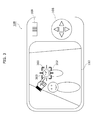
- FIG. 3 is a schematic diagram showing how to designate an enlargement area using the digital camera according to Embodiment 1.
- FIG. 4 illustrates an image size of the enlargement area.
- FIG. 5 illustrates an enlargement candidate area
- FIG. 6 is a flowchart showing an enlargement operation performed by the controller according to Embodiment 1.
- FIG. 7 illustrates how an area selection unit selects the enlargement area.
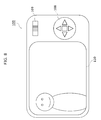
- FIG. 8 illustrates a liquid crystal monitor on which an enlarged video is displayed.
- FIG. 9 is a block diagram showing a detailed configuration of a controller according to Embodiment 2.
- FIG. 10 is a flowchart showing an enlargement operation performed by the controller according to Embodiment 2.
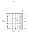
- FIG. 11 is a schematic diagram of the enlargement candidate area, for illustrating a calculation order of an evaluation value.
- FIG. 12 is a flowchart showing another example of the enlargement operation performed by the controller according to Embodiment 2.
- FIG. 13A shows an example of application of the three-dimensional video processing apparatus.
- FIG. 13B shows another example of application of the three-dimensional video processing apparatus.
- FIG. 14 shows yet another example of application of the three-dimensional video processing apparatus.
- Embodiment 1 is described below with reference to FIGS. 1 to 8 .
- a digital camera is taken as an example.
- FIG. 1 is a block diagram showing the configuration of the digital camera according to Embodiment 1.
- a digital camera 100 includes an optical system 101 , a CCD image sensor 102 , a video processing unit 103 , a memory 104 , a controller 105 , a card slot 106 , a memory card 107 , an operation member 108 , a zoom lever 109 , a liquid crystal monitor 110 , and an internal memory 111 .
- the optical system 101 forms a subject image of a first viewpoint that corresponds to one of the left eye image and the right eye image included in the 3D video. Furthermore, the optical system 101 forms a subject image of a second viewpoint that corresponds to the other one of the left eye image and the right eye image, which is different from the first viewpoint. Specifically, the optical system 101 includes two optical systems: a first optical system and a second optical system.
- the optical system 101 may be a single optical system, and may form subject images at different viewpoints depending on movement of the user to another capturing position. Specifically, the optical system 101 may be anything as long as the optical system 101 can form two subject images which are different from each other and for use in a 3D video. It is to be noted that the optical system 101 includes a zoom lens (not shown), an optical image stabilizer (OIS) (not shown), and a focus lens (not shown).
- OIS optical image stabilizer
- focus lens not shown
- the CCD image sensor 102 captures a subject image formed by the optical system 101 , to generate a video signal.
- the CCD image sensor 102 When a subject image of the first viewpoint is inputted from the optical system 101 , the CCD image sensor 102 generates a first viewpoint signal that is a video signal corresponding to the subject image of the first viewpoint.
- the CCD image sensor 102 when a subject image of the second viewpoint is inputted from the optical system 101 , the CCD image sensor 102 generates a second viewpoint signal that is a video signal corresponding to the subject image of the second viewpoint.
- the first viewpoint signal and the second viewpoint signal is referred to as a 3D video signal for three-dimensional viewing, or simply a video signal.
- the CCD image sensor 102 performs various operations such as exposure, transfer, electronic shutter, and the like.
- the video processing unit 103 performs various processing on the video signal generated by the CCD image sensor 102 , to generate image data to be displayed on the liquid crystal monitor 110 . Furthermore, the video processing unit 103 generates a video signal to be stored again in the memory card 107 , to the video signal generated by the CCD image sensor 102 . For example, the video processing unit 103 performs, on the video signal generated by the CCD image sensor 102 , various video processing such as gamma correction, white balance correction, defect correction, and the like, to generate a video signal to be stored again in the memory card 107 .
- various video processing such as gamma correction, white balance correction, defect correction, and the like
- the video processing unit 103 calculates a disparity amount per processing unit of the image of the first viewpoint signal and the second viewpoint signal which are obtained by the optical system 101 and the CCD image sensor 102 , by comparing a processing unit of one image with the corresponding processing unit of the other image. Then, the video processing unit 103 calculates a disparity histogram based on a frequency of occurrence of each disparity amount. Moreover, the video processing unit 103 compares the calculated histogram and a preset histogram pattern, to determine a capturing parameter for obtaining a predetermined three-dimensional effect.
- a processing unit in the video processing unit 103 is a pixel unit when the 3D video is divided by 4 ⁇ 4 pixel units. It is to be noted that the above processing unit may be a unit of arbitrary number of pixels, such as 8 ⁇ 8 pixel units, 16 ⁇ 16 pixel units, and so on. Furthermore, the disparity amount may be represented by any value as long as the value indicates a shift in the left and right direction between a processing unit of one image and the corresponding processing unit of the other image.
- the video processing unit 103 can calculate the disparity amount of the processing unit by selecting any one of an average value, a median value, and one, of the disparity amounts.
- the video processing unit 103 uses block matching when detecting a disparity amount.
- the block matching is processing to search out from a second viewpoint signal a block similar to, for example, 4 ⁇ 4 pixels block in the first viewpoint signal.
- the video processing unit 103 can be implemented with a digital signal processor (DSP), a microcomputer, or the like.
- DSP digital signal processor
- the disparity amount is a signed amount.
- the disparity amount is defined as a minus disparity amount, while when the video is displayed in a front side of the display screen of the liquid crystal monitor 110 , that is when the video is projecting toward the user, the disparity amount is signed with plus.
- the memory 104 serves as a work memory for the video processing unit 103 and the controller 105 .
- the following is accumulated temporarily in the memory 104 : the video signal processed by the video processing unit 103 ; or the image data inputted from the CCD image sensor 102 that is the data before being processed by the video processing unit 103 .
- a capturing condition of the optical system 101 and the CCD image sensor 102 at capturing is also accumulated temporarily in the memory 104 .
- a capturing condition stands for a subject distance, angle of view information, ISO sensitivity, shutter speed, exposure value, F value, inter-lens distance, time of capture, OIS shift amount, and the like.
- the memory 104 can be implemented using, for example, a dynamic random access memory (DRAM), a ferroelectric memory, or the like.
- DRAM dynamic random access memory
- ferroelectric memory or the like.
- controller 105 three-dimensional video processing apparatus.
- the controller 105 is a control means that controls the entire digital camera 100 .
- the controller 105 can be implemented using a semiconductor device or the like.
- the controller 105 may be implemented using only hardware, or by combining hardware and software.
- the controller 105 can also be implemented using a microcomputer or the like.
- FIG. 2 is a block diagram showing a detailed configuration of the controller 105 according to Embodiment 1.
- the controller 105 includes a video obtaining unit 201 , a disparity obtaining unit 202 , a determination unit 203 , an area selection unit 204 , and a position obtaining unit 205 .
- the image obtaining unit 201 obtains a video signal (3D video) stored in the memory 104 .
- the disparity obtaining unit 202 obtains a disparity amount per processing unit of the 3D video calculated by the video processing unit 103 .
- the determination unit 203 determines a size, on the display screen, of an enlargement area that is a part of the 3D video, based on a size of the display screen of the liquid crystal monitor 110 and a zoom magnification (predetermined magnification) inputted by the user from the zoom lever. Specifically, for example, the determination unit 203 determines, as the size of the enlargement area, the size obtained by dividing a length of each side of the display screen of the liquid crystal monitor 110 by a predetermined magnification.
- the position obtaining unit 205 obtains a position of a first area (hereinafter also referred to as enlargement instruction position), in the 3D video, that is the area the user desires to enlarge.
- the position of a first area is inputted by the user through the operation member 108 .
- the area selection unit 204 selects a part of the 3D video as the enlargement area, and outputs the video on which the enlargement processing is performed to the liquid crystal monitor 110 . How to select the enlargement area is described later.
- the memory card 107 can be attached and detached to the card slot 106 .
- the card slot 106 is mechanically and electrically connected to the memory card 107 .
- the memory card 107 internally includes a flash memory or a ferroelectric memory, and is a recording media in which data can be stored.
- the operation member 108 is a member that accepts an operation input to the digital camera 100 by the user, and is provided with a directional button and an enter button, for example.
- the directional button is a member through which the user operates an instruction cursor for designating a position on the image displayed on the liquid crystal monitor 110 .
- the enter button is a member through which the user determines the position indicated by the instruction cursor operated through the directional button.
- the zoom lever 109 is a member that accepts an instruction from the user to change the zoom magnification in the optical system 101 .
- the liquid crystal monitor 110 is a display device capable of displaying, on the display screen, a first viewpoint signal and a second viewpoint signal in a 2D or 3D manner.
- the above-mentioned first viewpoint signal and the second viewpoint signal are a video signal generated by the CCD image sensor 102 or video signals read from the memory card 107 .
- the liquid crystal monitor 110 is capable of displaying various setting information of the digital camera 100 .
- the liquid crystal monitor 110 is capable of displaying the exposure value, F value, shutter speed, ISO sensitivity, and the like, which are the capturing condition at capturing.
- the liquid crystal monitor 110 selects and displays one of the first viewpoint signal and the second viewpoint signal. Also, the liquid crystal monitor 110 may display the first viewpoint signal and the second viewpoint signal by splitting the screen into right and left or top and bottom. Also, the liquid crystal monitor 110 may display the first viewpoint signal and the second viewpoint signal alternately by each line. Specifically, the liquid crystal monitor 110 has a function to display a 2D video based on the first viewpoint signal and the second viewpoint signal when 2D displaying the video signal.
- the liquid crystal monitor 110 may display the first viewpoint signal and the second viewpoint signal using the frame sequential scheme, or by overlaying the first viewpoint signal and the second viewpoint signal.
- the internal memory 111 a control program and the like for controlling the entire digital camera 100 are stored.
- the internal memory 111 can be implemented using a flash memory, ferroelectric memory, or the like.
- the following describes enlargement operation for a video signal performed by the digital camera 100 .
- FIG. 3 shows a specific configuration of the digital camera 100 .
- the digital camera 100 includes a zoom lever 109 , an operation member 108 , and a liquid crystal monitor 110 , at the back. Specifically, the user can check a video displayed on the liquid crystal monitor 110 while capturing the video.
- the user designates an enlargement instruction position 300 to be displayed on the liquid crystal monitor 110 , using the operation member 108 of the digital camera 100 . Specifically, the user operates the operation member 108 to move the instruction cursor 302 . The user moves the instruction cursor 302 to a position of the first area 303 that the user desires to enlarge, and then presses the enter button of the operation member 108 . The position of the instruction cursor 302 at the time when the button is pressed is the enlargement instruction position 300 .
- the enlargement instruction position 300 may be designated through a touch operation, when the liquid crystal monitor 110 of the digital camera 100 has a touch sensor. In this case, the position where the touch operation is performed by the user on the display screen is the enlargement instruction position 300 .
- an enlargement candidate area that includes an area to be a candidate for the enlargement area.
- FIG. 4 illustrates an image size of the enlargement area.
- the enlargement candidate area is an area in which, when an arbitrary area having a size of the image size 301 is selected in the enlargement candidate area, the first area 303 is certainly included in the selected area.
- the first area is an area having a size of x5 pixels ⁇ y5 pixels as shown in FIG. 4 .
- FIG. 5 illustrates an enlargement candidate area
- the area selection unit 204 sets the enlargement candidate area 310 .
- the enlargement candidate area 310 is a search area in which the area selection unit 204 searches for a second area that can be the enlargement area.
- the second area certainly includes the first area 303 .
- the second area is an area: within the 3D video; including the first area 303 ; and having the size determined by the determination unit 203 within the 3D video.
- the area selection unit 204 sets, as the enlargement candidate area 310 , an area in a square shape and having tops at (x1 ⁇ x2/2, y1 ⁇ y2/2), (x1+x2/2, y1 ⁇ y2/2), (x1+x2/2, y1+y2/2), and (x1 ⁇ x2/2, y1+y2/2).
- FIG. 6 shows a flowchart of the enlargement operation performed by the controller 105 .
- the position obtaining unit 205 obtains an enlargement instruction position 300 (S 101 in FIG. 6 ).
- the enlargement instruction position 300 is designated by an operation by the user which has been described.
- the area selection unit 204 determines an enlargement candidate area 310 based on the image size 301 and the size of the first area 303 (S 102 in FIG. 6 ).
- the disparity obtaining unit 202 obtains a disparity amount of each of all of the processing units within the enlargement candidate area 310 (S 103 in FIG. 6 ).
- the area selection unit 204 selects, as the enlargement area, at least one of the second areas in which each of all of the included processing units have a disparity amount within a predetermined range, out of the selectable second areas within the enlargement candidate area 310 (S 104 in FIG. 6 ).
- FIG. 7 illustrates how the area selection unit 204 selects the enlargement area.
- the enlargement candidate area includes a plurality of second areas which the area selection unit 204 can select.
- the area selection unit 204 can select second areas 304 a through 304 e , and so on.
- the selection unit 204 selects the second area as an area that the user can view the area three-dimensionally appropriately after enlargement, that is, as the enlargement area.
- the area selection unit 204 selects the second area 304 e as the enlargement area 305 .
- the predetermined range is set at a range that allows the user to view the enlarged video three-dimensionally appropriately.
- the predetermined range may be set at a range in which the disparity amount of the enlarged video is between the upper limit and the lower limit of the disparity amount specified by 3DC Safety Guidelines.
- the area selection unit 204 and the video processing unit 103 generate an enlarged video that is a video obtained by enlarging the enlargement area, and display (output) the enlarged video on (to) the liquid crystal monitor 110 (S 105 in FIG. 6 ) as shown in FIG. 8 .
- the three-dimensional video processing apparatus is applied to the controller 105 of the digital camera 100 .
- the controller 105 includes a video obtaining unit 201 , a disparity obtaining unit 202 , a determination unit 203 , an area selection unit 204 , and a position obtaining unit 205 .
- the area that the user desires to enlarge is the first area.
- the area selection unit 204 selects, as the enlargement area, at least one specific second area that has disparity amounts within a predetermined range.
- the second areas are included in the part of the 3D video, and each includes the first area and has a size determined by the determination unit 203 .
- the area selection unit 204 can: enlarge the enlargement area including the area that the user desires to enlarge out of the 3D video while maintaining the predetermined magnification; and further make the enlarged video a video that the user can view three-dimensionally, appropriately and safely.
- the area selection unit 204 may select, as the enlargement area 305 , at least one of the second areas that includes processing units having a smallest disparity amount distribution.
- the user can view a safer enlarged video.
- the area selection unit 204 may select, as the enlargement area 305 , at least one of the second areas that has a least difference between an average value of disparity amounts of the processing units included in the first area and an average value of disparity amounts of the processing units included in the second area.
- the area selection unit 204 selects, as the enlargement area, at least one of the second areas that has disparity amounts close to the disparity amounts included in the first area 303 .
- the first area 303 is the area the user desires to enlarge. This makes the disparity amounts of the first area 303 and the disparity amounts of the peripheral area close. Therefore, the user can view the enlarged video three-dimensionally, naturally and effectively.
- the area selection unit 204 may select, as the enlargement area 305 , at least one of the second areas that is positioned closest to a position of the first area 303 on the display screen.
- the distance from the position of the first area 303 to the position of the second area is obtained using, for example, Euclidean distance from the enlargement instruction position 300 to the processing unit corresponding to the center position of the second area.
- the distance from the position of the first area 303 to the position of second area may be obtained using chessboard distance or city block distance.
- the first area 303 desired to be enlarged is displayed around the center of the enlarged video, which makes it even easier for the user to view the first area 303 .
- the disparity amount obtained by the disparity obtaining unit 202 may be obtained from a disparity map, based on the video obtained from the CCD image sensor 102 .
- the disparity map is generated in real time by the video processing unit 103 .
- the disparity amount obtained by the disparity obtaining unit 202 may be obtained from meta information of the three-dimensional video saved in the memory card 107 .
- the disparity amount obtained by the disparity obtaining unit 202 may not be the disparity amount per processing unit. It is sufficient if a judgment can be made on whether or not the maximum disparity (a disparity of a portion where the user perceives the video at the backmost and a disparity of a portion where the user perceives the video at the frontmost) of the second area is within a predetermined range.
- the aspect ratio of the enlargement area 305 is the same as the aspect ratio of the video before enlargement.
- Embodiment 2 The following describes Embodiment 2 with reference to FIGS. 9 to 12 .
- description is provided on an example in which the area selection unit uses an evaluation value to select an enlargement area.
- Embodiment 2 The entire configuration of a digital camera according to Embodiment 2 is the same as the configuration described with reference to FIGS. 1 and 3 .
- FIG. 9 is a block diagram showing a detailed configuration of the controller 105 according to Embodiment 2.
- the controller 105 includes an evaluation value calculation unit 206 , in addition to the constituent elements described in Embodiment 1.
- the evaluation value calculation unit 206 calculates an evaluation value C per processing unit.
- the evaluation value C of a processing unit is represented by a sum of: a first evaluation value representing an absolute value of a relative disparity amount of the processing unit obtained with reference to the disparity amount of a processing unit corresponding to the enlargement instruction position 300 ; and a second evaluation value representing a distance from the enlargement instruction position 300 to the processing unit.
- the evaluation value C decreases as the processing unit has a less difference from the disparity amount of the processing unit corresponding to the enlargement instruction position 300 .
- the evaluation value C decreases as the distance from the processing unit to the enlargement instruction position 300 is shorter.
- FIG. 10 shows a flowchart of the enlargement operation performed by the controller 105 according to Embodiment 2.
- the position obtaining unit 205 obtains an enlargement instruction position 300 (S 201 in FIG. 10 ).
- the position obtaining unit 202 obtains a disparity amount at the enlargement instruction position 300 (S 202 in FIG. 10 ). Specifically, the position obtaining unit 202 obtains a disparity amount of a processing unit corresponding to the enlargement instruction position 300 (hereinafter also referred to as a first processing unit).
- the area selection unit 204 determines an enlargement candidate area 310 based on the image size 301 and the size of the first area 303 (S 203 in FIG. 10 ).
- a vertical length ZH (length in x axis direction in FIG. 4 ) and a horizontal length ZW (length in y axis direction in FIG. 4 ) of the enlargement candidate area 310 are represented by Equation 1 below using, for example, a vertical length H and a horizontal length W of the liquid crystal monitor 110 and a predetermined magnification M.
- the center position of the enlargement candidate area 310 is the enlargement instruction position 300 .
- the evaluation value calculation unit 206 performs operation of S 204 through S 206 on all of the processing units within the enlargement candidate area 310 , to calculate the evaluation value for each processing unit.
- the evaluation value C calculated by the evaluation value calculation unit 206 is given by Expression 2 below, for example.
- ⁇ and ⁇ are arbitrary constants.
- [Math 2] C ⁇
- D is a relative disparity amount obtained with reference to the disparity amount of the first processing unit, and can be obtained by the following: [disparity amount of the processing unit] ⁇ [disparity amount of the enlargement instruction position].
- first evaluation value is a value that decreases as the disparity amount D of the processing unit is smaller.
- F is a distance from the enlargement instruction position 300 to the processing unit.
- ⁇ F second evaluation value
- the distance F is Euclidean distance on the image, however, the distance F may be, for example, chessboard distance on the image, or city block distance on the image.
- the evaluation value calculation unit 206 first obtains a disparity amount D of each processing unit through the disparity obtaining unit 202 (S 204 in FIG. 10 ), and obtains a distance F to each processing unit based on the video signal which the video obtaining unit 201 has obtained (S 205 in FIG. 10 ).
- the evaluation value calculation unit 206 calculates an evaluation value C of each processing unit from the disparity amount D and the distance F obtained, based on Equation 2 (S 206 in FIG. 10 ).
- the area selection unit 204 selects, as the enlargement area 305 , at least one of the second areas having the smallest sum of the evaluation value C out of all of the processing units included in the second area, out of the selectable second areas in the enlargement candidate area 310 (S 207 in FIG. 10 ).
- the enlargement area 305 selected by the area selection unit 204 can be given by Expression 3 below, for example.
- the area selection unit 204 selects, as the enlargement area 305 , at least one of the second areas that includes processing units having a smallest sum of the evaluation values C. Specifically, a second area is less likely to be selected as the enlargement area 305 , as the second area includes more processing units each having a great disparity amount D. Also, a second area is less likely to be selected as the enlargement area 305 as the second area is positioned farther from the enlargement instruction position 300 .
- the area selection unit 204 and the video processing unit 103 generate an enlarged video that is a video obtained by enlarging the enlargement area 305 based on the enlargement area 305 , and displays (outputs) the enlarged video on (to) the liquid crystal monitor 110 (S 208 in FIG. 10 ).
- the evaluation value C calculated by the evaluation value calculation unit 206 is given by Expression 4 below, for example.
- ⁇ and ⁇ , and T are arbitrary constants.
- the evaluation value C becomes a large value irrespective of the distance F.
- the enlargement area 305 selected by the area selection unit 204 can be given by Expression 5 below, for example.
- S is an arbitrary constant.
- the evaluation value calculation unit 206 assigns a label “1” to the processing unit.
- the label “1” indicates that the processing unit is to be hidden. It is to be noted that when the evaluation value C of the processing unit is less than the predetermined threshold S, a label “0”, that is preset, is assigned to the processing unit.
- the above predetermined threshold is a threshold which is set preliminarily, but may also be user-changeable.
- a digital camera 100 can be provided in which whether the processing unit having a great disparity amount D is to be shown or hidden can be set according to the three-dimensional viewing capability of the user.
- the evaluation value calculation unit 206 does not have to calculate an evaluation value C for each of the all of the processing units included in the enlargement candidate area 310 .
- FIG. 11 is a schematic diagram of the enlargement candidate area 310 which illustrates calculation order for the evaluation value C.
- FIG. 12 shows a flowchart showing another example of the enlargement operation performed by the controller 105 according to Embodiment 2.
- the evaluation value calculation unit 206 calculates the evaluation value C of each processing unit starting from a first processing unit 300 a , as the center, and expanding the search range to the periphery, one adjacent processing unit at a time.
- the first processing unit 300 a is the processing unit corresponding to the designated enlargement instruction position 300 .
- the evaluation value C is calculated for eight processing units each having a chessboard distance 1 on the image from the first processing unit 300 a , in the order of clockwise rotation direction starting from the processing unit 300 b positioned immediately below the first processing unit 300 a.
- the evaluation value C is calculated for 16 processing units each having a chessboard distance 2 on the image from the first processing unit 300 a , in the order of clockwise rotation direction starting from the processing unit 300 c .
- the number “0” or “1” assigned to each processing unit in FIG. 11 is a label indicating whether the above processing unit is the processing unit to be shown or the processing unit to be hidden.
- evaluation value calculation shown in S 209 , S 204 through S 206 , S 210 , and S 211 in FIG. 12 is performed on each processing unit.
- the evaluation value calculation unit 206 determines, for each processing unit, whether or not the processing unit is linked from the enlargement instruction position 300 (first processing unit 300 a ) (S 209 in FIG. 12 ).
- “linked” means that the processing unit is linked to the first processing unit 300 a via one or more processing units having the evaluation value C less than the predetermined threshold S (the processing units assigned 0 in FIG. 11 ).
- the processing unit when it is possible to arrive, from a processing unit, at the first processing unit 300 a by tracking the adjacent processing units each having the evaluation value C less than the predetermined threshold S (when there is a path of processing units to the first processing unit), the processing unit can be said to be linked to the first processing unit.
- the “adjacent processing unit” stands only for the processing unit adjacent to a processing unit in the top, bottom, right, and left directions, the “adjacent processing unit” may also include a processing unit adjacent in the diagonal direction.
- calculation of evaluation value C is performed (S 204 through S 206 in FIG. 12 ), and determination is made on whether or not the evaluation value C of the processing unit is greater than or equal to the threshold S (S 210 in FIG. 12 ).
- a label “1” is assigned to the processing unit.
- the label “1” indicates that the processing unit is to be hidden.
- the processing unit 300 c is the processing unit assigned the label “1”.
- a label “1” is assigned to the processing unit.
- the label “1” indicates that the processing unit is to be hidden (S 211 in FIG. 12 ).
- the processing unit 300 c is the processing unit assigned the label “1”.
- a label “0”, that is preset, is assigned to the processing unit.
- the label of the processing unit 300 b is “0”.
- calculation of evaluation value C (S 204 through S 206 , S 210 , and S 211 in FIG. 12 ) is not performed.
- the evaluation value C is not calculated for the processing units 300 d through 300 h.
- the area selection unit 204 selects, as the enlargement area 305 , at least one of the second areas having the smallest sum of the evaluation value C out of all of the processing units included in the second area, out of the selectable second areas in the area in which the evaluation value is calculated within the enlargement candidate area 310 (S 207 in FIG. 10 ).
- the area selection unit 204 and the video processing unit 103 generate an enlarged video that is a video obtained by enlarging the enlargement area 305 , and display on (output to) the liquid crystal monitor 110 the enlarged video (S 208 in FIG. 12 ).
- the controller 105 (three-dimensional video processing apparatus) further includes the evaluation value calculation unit 206 , and the area selection unit 204 selects the enlargement area based on the evaluation value C calculated by the evaluation value calculation unit 206 .
- the evaluation value C is a sum of a first evaluation value ⁇
- the area selection unit 204 can select the enlargement area 305 with taking both of the disparity amount D and the distance F into consideration.
- the evaluation value C is not limited to those described in Embodiment 2.
- ⁇ may be 0. Even when ⁇ is 0, the area selection unit 204 can enlarge the enlargement area by a predetermined magnification, as a video which the user can view three-dimensionally, appropriately and safely.
- the disparity amount D may be an absolute disparity amount.
- the evaluation value calculation unit 206 in Embodiment 2 calculates the evaluation value of each of the processing units which are linked to the first processing unit 300 a via the processing unit having the evaluation value C less than the predetermined threshold S.
- the evaluation value C calculation processing can be omitted for the areas that cannot be a candidate for the enlargement area, which can reduce costs for evaluation value calculation and the load placed by the evaluation value calculation.
- Embodiments 1 and 2 are examples of the technique disclosed in the present application.
- the technique in the present disclosure is not limited to the above, and may be applied to embodiments obtained by modifying, replacing, adding, and omitting the above embodiments as appropriate. It is also possible to combine each of the constituent elements described in Embodiment 1 and Embodiment 2 above to make a new embodiment.
- Embodiment 1 and Embodiment 2 an example is described in which the three-dimensional video processing apparatus according to the present disclosure is applied to a digital camera as shown in FIG. 13A .
- the three-dimensional video processing apparatus is applicable also to a digital video camera as shown in FIG. 13B .
- the three-dimensional video processing apparatus is applicable to a TV 700 shown FIG. 14 .
- the three-dimensional video processing apparatus performs video enlargement processing on the video obtained from TV broadcasting, a Blu-ray player 710 , or a set-top box 720 shown in FIG. 14 .
- the three-dimensional video processing apparatus is also applicable to the Blu-ray player 710 .
- the three-dimensional video processing apparatus can perform video enlargement processing for a video obtained from any kind of inserted recording medium, such as a Blu-ray disc, digital versatile disc (DVD), hard disc drive (HDD), or the like.
- the three-dimensional video processing apparatus is also applicable to a set-top box 720 .
- the three-dimensional video processing apparatus can perform the video enlargement processing.
- each of the aforementioned apparatuses can be implemented with a computer system including a microprocessor, a ROM, a RAM, a hard disk unit, a display unit, a keyboard, a mouse, and the like.
- a computer program is stored in the RAM or hard disk unit.
- the respective apparatuses achieve their functions through the microprocessor's operation according to the computer program.
- the computer program is configured by combining a plurality of instruction codes indicating instructions for the computer, in order to achieve predetermined functions.
- a part or all of the constituent elements included in each of the apparatuses above may include a single System Large Scale Integration (LSI).
- the System LSI is a super multifunctional LSI manufactured by integrating plural constituent elements on a single chip, and is specifically a computer system including a microprocessor, a ROM, a RAM, and so on.
- the ROM has a computer program stored. As the microprocessor loads a computer program from the ROM to the RAM and operates arithmetic operation or the like according to the loaded computer program, the system LSI performs its functions.
- each of the respective apparatuses may be configured as an IC card which can be attached and detached from the respective apparatuses or as a stand-alone module.
- the IC card or the module may be a computer system including the microprocessor, ROM, RAM, and the like.
- the IC card or the module may also include the aforementioned super-multi-function LSI.
- the IC card or the module achieves its function through the microprocessor's operation according to the computer program.
- the IC card or the module may have tamper resistant.
- the present disclosure may be implemented with the method described above.
- the present disclosure may also be implemented with a computer program which implements such a method with a computer or a digital signal formed of a computer program.
- the present invention may also be implemented with a computer-readable recording medium, for example, a flexible disk, a hard disk, a CD-ROM, an MO, a DVD, a DVD-ROM, a DVD-RAM, a Blu-ray Disc (BD), a semiconductor memory, or the like, on which such a computer program or digital signal is recorded.
- a computer-readable recording medium for example, a flexible disk, a hard disk, a CD-ROM, an MO, a DVD, a DVD-ROM, a DVD-RAM, a Blu-ray Disc (BD), a semiconductor memory, or the like, on which such a computer program or digital signal is recorded.
- the present invention may also be implemented with the digital signal recorded on these recording media.
- the present invention may also be realized by the transmission of the aforementioned computer program or digital signal via a telecommunication line, a wireless or wired communication line, a network represented by the Internet, a data broadcast and so forth.
- the present invention may also be a computer system including a microprocessor and a memory, in which the memory stores the aforementioned computer program and the microprocessor operates according to the computer program.
- constituent elements seen in the Drawings and Specification may include not only constituent elements necessary for solving the problem but also some constituent elements which are not necessary for solving the problem in order to exemplify the above technique. Therefore, even when some unnecessary constituent elements are seen in the attached Drawings or Specification, it should not be acknowledged immediately that the unnecessary constituent elements are necessary.
- the three-dimensional video processing apparatus and the three-dimensional video processing method according to one or more exemplary embodiments disclosed herein are capable of enlarging a three-dimensional video by a predetermined magnification which allows a user to view the video safely, and are useful as a digital camera, a display, and the like for displaying a three-dimensional video.
Abstract
Description
- [PTL 1] Japanese Patent No. 4442190
[Math 2]
C=α·|D|+β·
Claims (8)
Applications Claiming Priority (3)
| Application Number | Priority Date | Filing Date | Title |
|---|---|---|---|
| JP2011204088 | 2011-09-20 | ||
| JP2011-204088 | 2011-09-20 | ||
| PCT/JP2012/005253 WO2013042311A1 (en) | 2011-09-20 | 2012-08-22 | Stereoscopic video processing device and stereoscopic video processing method |
Related Parent Applications (1)
| Application Number | Title | Priority Date | Filing Date |
|---|---|---|---|
| PCT/JP2012/005253 Continuation WO2013042311A1 (en) | 2011-09-20 | 2012-08-22 | Stereoscopic video processing device and stereoscopic video processing method |
Publications (2)
| Publication Number | Publication Date |
|---|---|
| US20130242065A1 US20130242065A1 (en) | 2013-09-19 |
| US9313477B2 true US9313477B2 (en) | 2016-04-12 |
Family
ID=47914105
Family Applications (1)
| Application Number | Title | Priority Date | Filing Date |
|---|---|---|---|
| US13/889,900 Active 2033-09-03 US9313477B2 (en) | 2011-09-20 | 2013-05-08 | Three-dimensional video processing apparatus and three-dimensional video processing method |
Country Status (3)
| Country | Link |
|---|---|
| US (1) | US9313477B2 (en) |
| JP (1) | JP5281720B1 (en) |
| WO (1) | WO2013042311A1 (en) |
Families Citing this family (1)
| Publication number | Priority date | Publication date | Assignee | Title |
|---|---|---|---|---|
| US9538081B1 (en) | 2013-03-14 | 2017-01-03 | Amazon Technologies, Inc. | Depth-based image stabilization |
Citations (30)
| Publication number | Priority date | Publication date | Assignee | Title |
|---|---|---|---|---|
| JPH08317429A (en) | 1995-05-23 | 1996-11-29 | Matsushita Electric Ind Co Ltd | Stereoscopic electronic zoom device and stereoscopic picture quality controller |
| US5786847A (en) * | 1995-06-09 | 1998-07-28 | Canon Kabushiki Kaisha | Apparatus for adjusting the convergence in a stereoscopic image system |
| US6512892B1 (en) | 1999-09-15 | 2003-01-28 | Sharp Kabushiki Kaisha | 3D camera |
| JP3568195B2 (en) | 1999-09-15 | 2004-09-22 | シャープ株式会社 | 3D image generation method |
| JP2004349736A (en) | 2003-05-08 | 2004-12-09 | Sharp Corp | Apparatus and program for stereoscopic image processing, and recording medium recorded the program |
| JP2005073013A (en) | 2003-08-26 | 2005-03-17 | Sharp Corp | Device and method for stereo image display, program for making computer execute the method, and recording medium recording the program |
| JP2005128897A (en) | 2003-10-24 | 2005-05-19 | Sony Corp | Stereoscopic image processor |
| JP2005130313A (en) | 2003-10-24 | 2005-05-19 | Sony Corp | Stereoscopic vision image processing device |
| US20060192776A1 (en) * | 2003-04-17 | 2006-08-31 | Toshio Nomura | 3-Dimensional image creation device, 3-dimensional image reproduction device, 3-dimensional image processing device, 3-dimensional image processing program, and recording medium containing the program |
| JP4442190B2 (en) | 2003-10-24 | 2010-03-31 | ソニー株式会社 | Stereoscopic image processing device |
| US20100201789A1 (en) * | 2009-01-05 | 2010-08-12 | Fujifilm Corporation | Three-dimensional display device and digital zoom correction method |
| JP2010213084A (en) | 2009-03-11 | 2010-09-24 | Fujifilm Corp | Imaging apparatus, image correction method, and image correction program |
| US20110018969A1 (en) * | 2009-07-21 | 2011-01-27 | Fujifilm Corporation | Image reproducing apparatus and image reproducing method |
| US20110019989A1 (en) | 2009-07-24 | 2011-01-27 | Koichi Tanaka | Imaging device and imaging method |
| US20110175907A1 (en) * | 2010-01-18 | 2011-07-21 | Sony Corporation | Image processing apparatus, image processing method, and program |
| JP2011176699A (en) | 2010-02-25 | 2011-09-08 | Casio Computer Co Ltd | Imaging apparatus, display method, and, program |
| US20110292178A1 (en) * | 2010-05-28 | 2011-12-01 | Qualcomm Incorporated | Three-dimensional image processing |
| US20110304714A1 (en) * | 2010-06-14 | 2011-12-15 | Nintendo Co., Ltd. | Storage medium storing display control program for providing stereoscopic display desired by user with simpler operation, display control device, display control method, and display control system |
| US20120011464A1 (en) * | 2010-07-07 | 2012-01-12 | Sony Corporation | Display control device, display control method, and program |
| US20120019527A1 (en) * | 2010-07-26 | 2012-01-26 | Olympus Imaging Corp. | Display apparatus, display method, and computer-readable recording medium |
| US20120098938A1 (en) * | 2010-10-25 | 2012-04-26 | Jin Elaine W | Stereoscopic imaging systems with convergence control for reducing conflicts between accomodation and convergence |
| US20120108328A1 (en) * | 2010-01-14 | 2012-05-03 | Nintendo Co., Ltd. | Handheld information processing apparatus and handheld game apparatus |
| US20120133645A1 (en) * | 2010-11-26 | 2012-05-31 | Hayang Jung | Mobile terminal and operation control method thereof |
| US20130009949A1 (en) * | 2011-07-05 | 2013-01-10 | Texas Instruments Incorporated | Method, system and computer program product for re-convergence of a stereoscopic image |
| US20130038699A1 (en) * | 2010-03-29 | 2013-02-14 | Fujifilm Corporation | Stereoscopic imaging device, image reproducing device, and editing software |
| US20130083174A1 (en) * | 2010-05-31 | 2013-04-04 | Fujifilm Corporation | Stereoscopic image control apparatus, and method and program for controlling operation of same |
| US20130088573A1 (en) * | 2011-05-27 | 2013-04-11 | Warner Bros. | Methods for controlling scene, camera and viewing parameters for altering perception of 3d imagery |
| US20130100253A1 (en) * | 2010-06-30 | 2013-04-25 | Fujifilm Corporation | Image processing device, imaging capturing device, and method for processing image |
| US20130169633A1 (en) * | 2010-09-15 | 2013-07-04 | Sharp Kabushiki Kaisha | Stereoscopic image generation device, stereoscopic image display device, stereoscopic image adjustment method, program for causing computer to execute stereoscopic image adjustment method, and recording medium on which the program is recorded |
| US20150163475A1 (en) * | 2009-09-09 | 2015-06-11 | Mattel, Inc. | Method and system for disparity adjustment during stereoscopic zoom |
-
2012
- 2012-08-22 JP JP2012555627A patent/JP5281720B1/en not_active Expired - Fee Related
- 2012-08-22 WO PCT/JP2012/005253 patent/WO2013042311A1/en active Application Filing
-
2013
- 2013-05-08 US US13/889,900 patent/US9313477B2/en active Active
Patent Citations (39)
| Publication number | Priority date | Publication date | Assignee | Title |
|---|---|---|---|---|
| JPH08317429A (en) | 1995-05-23 | 1996-11-29 | Matsushita Electric Ind Co Ltd | Stereoscopic electronic zoom device and stereoscopic picture quality controller |
| US5786847A (en) * | 1995-06-09 | 1998-07-28 | Canon Kabushiki Kaisha | Apparatus for adjusting the convergence in a stereoscopic image system |
| US6512892B1 (en) | 1999-09-15 | 2003-01-28 | Sharp Kabushiki Kaisha | 3D camera |
| JP3568195B2 (en) | 1999-09-15 | 2004-09-22 | シャープ株式会社 | 3D image generation method |
| US6798406B1 (en) | 1999-09-15 | 2004-09-28 | Sharp Kabushiki Kaisha | Stereo images with comfortable perceived depth |
| US20060192776A1 (en) * | 2003-04-17 | 2006-08-31 | Toshio Nomura | 3-Dimensional image creation device, 3-dimensional image reproduction device, 3-dimensional image processing device, 3-dimensional image processing program, and recording medium containing the program |
| US7889196B2 (en) | 2003-04-17 | 2011-02-15 | Sharp Kabushiki Kaisha | 3-dimensional image creating apparatus, 3-dimensional image reproducing apparatus, 3-dimensional image processing apparatus, 3-dimensional image processing program and recording medium recorded with the program |
| US20100039499A1 (en) | 2003-04-17 | 2010-02-18 | Toshio Nomura | 3-dimensional image creating apparatus, 3-dimensional image reproducing apparatus, 3-dimensional image processing apparatus, 3-dimensional image processing program and recording medium recorded with the program |
| US7636088B2 (en) | 2003-04-17 | 2009-12-22 | Sharp Kabushiki Kaisha | 3-Dimensional image creation device, 3-dimensional image reproduction device, 3-dimensional image processing device, 3-dimensional image processing program, and recording medium containing the program |
| JP2004349736A (en) | 2003-05-08 | 2004-12-09 | Sharp Corp | Apparatus and program for stereoscopic image processing, and recording medium recorded the program |
| JP2005073013A (en) | 2003-08-26 | 2005-03-17 | Sharp Corp | Device and method for stereo image display, program for making computer execute the method, and recording medium recording the program |
| JP2005130313A (en) | 2003-10-24 | 2005-05-19 | Sony Corp | Stereoscopic vision image processing device |
| JP2005128897A (en) | 2003-10-24 | 2005-05-19 | Sony Corp | Stereoscopic image processor |
| JP4442190B2 (en) | 2003-10-24 | 2010-03-31 | ソニー株式会社 | Stereoscopic image processing device |
| US20100201789A1 (en) * | 2009-01-05 | 2010-08-12 | Fujifilm Corporation | Three-dimensional display device and digital zoom correction method |
| JP2010213084A (en) | 2009-03-11 | 2010-09-24 | Fujifilm Corp | Imaging apparatus, image correction method, and image correction program |
| US8379113B2 (en) | 2009-03-11 | 2013-02-19 | Fujifilm Corporation | Imaging apparatus, image correction method, and computer-readable recording medium |
| US20110292227A1 (en) | 2009-03-11 | 2011-12-01 | Michitaka Nakazawa | Imaging apparatus, image correction method, and computer-readable recording medium |
| US20110018969A1 (en) * | 2009-07-21 | 2011-01-27 | Fujifilm Corporation | Image reproducing apparatus and image reproducing method |
| JP2011029700A (en) | 2009-07-21 | 2011-02-10 | Fujifilm Corp | Image reproducing apparatus and method |
| JP2011029905A (en) | 2009-07-24 | 2011-02-10 | Fujifilm Corp | Imaging device, method and program |
| US8135270B2 (en) | 2009-07-24 | 2012-03-13 | Fujifilm Corporation | Imaging device and imaging method |
| US20110019989A1 (en) | 2009-07-24 | 2011-01-27 | Koichi Tanaka | Imaging device and imaging method |
| US20150163475A1 (en) * | 2009-09-09 | 2015-06-11 | Mattel, Inc. | Method and system for disparity adjustment during stereoscopic zoom |
| US20120108328A1 (en) * | 2010-01-14 | 2012-05-03 | Nintendo Co., Ltd. | Handheld information processing apparatus and handheld game apparatus |
| US20110175907A1 (en) * | 2010-01-18 | 2011-07-21 | Sony Corporation | Image processing apparatus, image processing method, and program |
| JP2011176699A (en) | 2010-02-25 | 2011-09-08 | Casio Computer Co Ltd | Imaging apparatus, display method, and, program |
| US20130038699A1 (en) * | 2010-03-29 | 2013-02-14 | Fujifilm Corporation | Stereoscopic imaging device, image reproducing device, and editing software |
| US20110292178A1 (en) * | 2010-05-28 | 2011-12-01 | Qualcomm Incorporated | Three-dimensional image processing |
| US20130083174A1 (en) * | 2010-05-31 | 2013-04-04 | Fujifilm Corporation | Stereoscopic image control apparatus, and method and program for controlling operation of same |
| US20110304714A1 (en) * | 2010-06-14 | 2011-12-15 | Nintendo Co., Ltd. | Storage medium storing display control program for providing stereoscopic display desired by user with simpler operation, display control device, display control method, and display control system |
| US20130100253A1 (en) * | 2010-06-30 | 2013-04-25 | Fujifilm Corporation | Image processing device, imaging capturing device, and method for processing image |
| US20120011464A1 (en) * | 2010-07-07 | 2012-01-12 | Sony Corporation | Display control device, display control method, and program |
| US20120019527A1 (en) * | 2010-07-26 | 2012-01-26 | Olympus Imaging Corp. | Display apparatus, display method, and computer-readable recording medium |
| US20130169633A1 (en) * | 2010-09-15 | 2013-07-04 | Sharp Kabushiki Kaisha | Stereoscopic image generation device, stereoscopic image display device, stereoscopic image adjustment method, program for causing computer to execute stereoscopic image adjustment method, and recording medium on which the program is recorded |
| US20120098938A1 (en) * | 2010-10-25 | 2012-04-26 | Jin Elaine W | Stereoscopic imaging systems with convergence control for reducing conflicts between accomodation and convergence |
| US20120133645A1 (en) * | 2010-11-26 | 2012-05-31 | Hayang Jung | Mobile terminal and operation control method thereof |
| US20130088573A1 (en) * | 2011-05-27 | 2013-04-11 | Warner Bros. | Methods for controlling scene, camera and viewing parameters for altering perception of 3d imagery |
| US20130009949A1 (en) * | 2011-07-05 | 2013-01-10 | Texas Instruments Incorporated | Method, system and computer program product for re-convergence of a stereoscopic image |
Non-Patent Citations (1)
| Title |
|---|
| International Search Report issued in International Patent Application No. PCT/JP2012/005253 mailed on Nov. 20, 2012. |
Also Published As
| Publication number | Publication date |
|---|---|
| JP5281720B1 (en) | 2013-09-04 |
| JPWO2013042311A1 (en) | 2015-03-26 |
| WO2013042311A1 (en) | 2013-03-28 |
| US20130242065A1 (en) | 2013-09-19 |
Similar Documents
| Publication | Publication Date | Title |
|---|---|---|
| US9779539B2 (en) | Image processing apparatus and image processing method | |
| CN103039066B (en) | Imaging device, image processing apparatus and image processing method | |
| US20120026165A1 (en) | Image Processing Apparatus and Method, and Program | |
| US20110187834A1 (en) | Recording device and recording method, image processing device and image processing method, and program | |
| JP5526233B2 (en) | Stereoscopic image photographing apparatus and control method thereof | |
| US20130071013A1 (en) | Video processing device, video processing method, program | |
| US20130069864A1 (en) | Display apparatus, display method, and program | |
| US20130083174A1 (en) | Stereoscopic image control apparatus, and method and program for controlling operation of same | |
| JP2008262333A (en) | Road surface discrimination device and road surface discrimination method | |
| US20160353079A1 (en) | Image processing apparatus, image processing method, and storage medium | |
| US20150292871A1 (en) | Image processing apparatus and image processing method | |
| US10438402B2 (en) | Image processing apparatus, image processing system, image processing method, and storage medium | |
| US20130027520A1 (en) | 3d image recording device and 3d image signal processing device | |
| US11184545B2 (en) | Display control apparatus, imaging apparatus, control method for display apparatus, and non-transitory computer readable medium | |
| US8849012B2 (en) | Image processing apparatus and method and computer readable medium having a program for processing stereoscopic image | |
| US9313477B2 (en) | Three-dimensional video processing apparatus and three-dimensional video processing method | |
| US20140168394A1 (en) | Image processing device, stereoscopic image display, and image processing method | |
| WO2012120880A1 (en) | 3d image output device and 3d image output method | |
| US20170289493A1 (en) | Projection apparatus, image processing apparatus, and image processing method | |
| JP2023033355A (en) | Image processing device and control method therefor | |
| US20130106850A1 (en) | Representative image decision apparatus, image compression apparatus, and methods and programs for controlling operation of same | |
| JP4960442B2 (en) | UPSHOT DETECTING DEVICE AND METHOD, ELECTRONIC DEVICE, AND COMPUTER PROGRAM | |
| US20170034423A1 (en) | Image capturing apparatus | |
| WO2018189961A1 (en) | Image processing device, terminal device, and image processing program | |
| US9076215B2 (en) | Arithmetic processing device |
Legal Events
| Date | Code | Title | Description |
|---|---|---|---|
| AS | Assignment |
Owner name: PANASONIC CORPORATION, JAPAN Free format text: ASSIGNMENT OF ASSIGNORS INTEREST;ASSIGNORS:KOYAMA, TAKAYOSHI;TSUDA, KENJIRO;OKIMOTO, YOSHIYUKI;REEL/FRAME:032046/0366 Effective date: 20130403 |
|
| AS | Assignment |
Owner name: PANASONIC INTELLECTUAL PROPERTY MANAGEMENT CO., LTD., JAPAN Free format text: ASSIGNMENT OF ASSIGNORS INTEREST;ASSIGNOR:PANASONIC CORPORATION;REEL/FRAME:034194/0143 Effective date: 20141110 Owner name: PANASONIC INTELLECTUAL PROPERTY MANAGEMENT CO., LT Free format text: ASSIGNMENT OF ASSIGNORS INTEREST;ASSIGNOR:PANASONIC CORPORATION;REEL/FRAME:034194/0143 Effective date: 20141110 |
|
| STCF | Information on status: patent grant |
Free format text: PATENTED CASE |
|
| MAFP | Maintenance fee payment |
Free format text: PAYMENT OF MAINTENANCE FEE, 4TH YEAR, LARGE ENTITY (ORIGINAL EVENT CODE: M1551); ENTITY STATUS OF PATENT OWNER: LARGE ENTITY Year of fee payment: 4 |
|
| AS | Assignment |
Owner name: PANASONIC INTELLECTUAL PROPERTY MANAGEMENT CO., LTD., JAPAN Free format text: CORRECTIVE ASSIGNMENT TO CORRECT THE ERRONEOUSLY FILED APPLICATION NUMBERS 13/384239, 13/498734, 14/116681 AND 14/301144 PREVIOUSLY RECORDED ON REEL 034194 FRAME 0143. ASSIGNOR(S) HEREBY CONFIRMS THE ASSIGNMENT;ASSIGNOR:PANASONIC CORPORATION;REEL/FRAME:056788/0362 Effective date: 20141110 |
|
| FEPP | Fee payment procedure |
Free format text: MAINTENANCE FEE REMINDER MAILED (ORIGINAL EVENT CODE: REM.); ENTITY STATUS OF PATENT OWNER: LARGE ENTITY |