US9148579B1 - Fusion night vision system - Google Patents
Fusion night vision system Download PDFInfo
- Publication number
- US9148579B1 US9148579B1 US13/828,816 US201313828816A US9148579B1 US 9148579 B1 US9148579 B1 US 9148579B1 US 201313828816 A US201313828816 A US 201313828816A US 9148579 B1 US9148579 B1 US 9148579B1
- Authority
- US
- United States
- Prior art keywords
- image
- night vision
- vision system
- optical element
- output
- Prior art date
- Legal status (The legal status is an assumption and is not a legal conclusion. Google has not performed a legal analysis and makes no representation as to the accuracy of the status listed.)
- Active, expires
Links
- 230000004297 night vision Effects 0.000 title claims abstract description 34
- 230000004927 fusion Effects 0.000 title claims abstract description 23
- 230000003287 optical effect Effects 0.000 claims abstract description 23
- 238000012545 processing Methods 0.000 claims description 7
- 229910000530 Gallium indium arsenide Inorganic materials 0.000 claims description 3
- 239000000203 mixture Substances 0.000 description 13
- 238000010586 diagram Methods 0.000 description 6
- 238000005286 illumination Methods 0.000 description 6
- 230000008901 benefit Effects 0.000 description 4
- 230000005855 radiation Effects 0.000 description 4
- 238000000034 method Methods 0.000 description 3
- 239000000779 smoke Substances 0.000 description 3
- 238000001228 spectrum Methods 0.000 description 3
- 239000000835 fiber Substances 0.000 description 2
- 230000008569 process Effects 0.000 description 2
- 239000004576 sand Substances 0.000 description 2
- 239000000853 adhesive Substances 0.000 description 1
- 230000001070 adhesive effect Effects 0.000 description 1
- 230000002411 adverse Effects 0.000 description 1
- 238000003491 array Methods 0.000 description 1
- 230000002238 attenuated effect Effects 0.000 description 1
- 235000019994 cava Nutrition 0.000 description 1
- 230000008859 change Effects 0.000 description 1
- 238000004891 communication Methods 0.000 description 1
- 238000012937 correction Methods 0.000 description 1
- 239000000428 dust Substances 0.000 description 1
- 238000003708 edge detection Methods 0.000 description 1
- 238000005516 engineering process Methods 0.000 description 1
- 230000004438 eyesight Effects 0.000 description 1
- 230000006870 function Effects 0.000 description 1
- 239000011521 glass Substances 0.000 description 1
- 238000003384 imaging method Methods 0.000 description 1
- 238000002329 infrared spectrum Methods 0.000 description 1
- 239000004973 liquid crystal related substance Substances 0.000 description 1
- 230000007246 mechanism Effects 0.000 description 1
- 238000012986 modification Methods 0.000 description 1
- 230000004048 modification Effects 0.000 description 1
- 229920001296 polysiloxane Polymers 0.000 description 1
- 230000035945 sensitivity Effects 0.000 description 1
- 238000007493 shaping process Methods 0.000 description 1
- 238000001931 thermography Methods 0.000 description 1
Images


Classifications
-
- H—ELECTRICITY
- H04—ELECTRIC COMMUNICATION TECHNIQUE
- H04N—PICTORIAL COMMUNICATION, e.g. TELEVISION
- H04N23/00—Cameras or camera modules comprising electronic image sensors; Control thereof
- H04N23/70—Circuitry for compensating brightness variation in the scene
-
- H04N5/235—
-
- G—PHYSICS
- G01—MEASURING; TESTING
- G01J—MEASUREMENT OF INTENSITY, VELOCITY, SPECTRAL CONTENT, POLARISATION, PHASE OR PULSE CHARACTERISTICS OF INFRARED, VISIBLE OR ULTRAVIOLET LIGHT; COLORIMETRY; RADIATION PYROMETRY
- G01J5/00—Radiation pyrometry, e.g. infrared or optical thermometry
- G01J5/02—Constructional details
- G01J5/025—Interfacing a pyrometer to an external device or network; User interface
-
- G—PHYSICS
- G01—MEASURING; TESTING
- G01J—MEASUREMENT OF INTENSITY, VELOCITY, SPECTRAL CONTENT, POLARISATION, PHASE OR PULSE CHARACTERISTICS OF INFRARED, VISIBLE OR ULTRAVIOLET LIGHT; COLORIMETRY; RADIATION PYROMETRY
- G01J5/00—Radiation pyrometry, e.g. infrared or optical thermometry
- G01J5/02—Constructional details
- G01J5/0265—Handheld, portable
-
- G—PHYSICS
- G01—MEASURING; TESTING
- G01J—MEASUREMENT OF INTENSITY, VELOCITY, SPECTRAL CONTENT, POLARISATION, PHASE OR PULSE CHARACTERISTICS OF INFRARED, VISIBLE OR ULTRAVIOLET LIGHT; COLORIMETRY; RADIATION PYROMETRY
- G01J5/00—Radiation pyrometry, e.g. infrared or optical thermometry
- G01J5/02—Constructional details
- G01J5/0275—Control or determination of height or distance or angle information for sensors or receivers
-
- G—PHYSICS
- G01—MEASURING; TESTING
- G01J—MEASUREMENT OF INTENSITY, VELOCITY, SPECTRAL CONTENT, POLARISATION, PHASE OR PULSE CHARACTERISTICS OF INFRARED, VISIBLE OR ULTRAVIOLET LIGHT; COLORIMETRY; RADIATION PYROMETRY
- G01J5/00—Radiation pyrometry, e.g. infrared or optical thermometry
- G01J5/02—Constructional details
- G01J5/08—Optical arrangements
- G01J5/0859—Sighting arrangements, e.g. cameras
-
- G—PHYSICS
- G02—OPTICS
- G02B—OPTICAL ELEMENTS, SYSTEMS OR APPARATUS
- G02B23/00—Telescopes, e.g. binoculars; Periscopes; Instruments for viewing the inside of hollow bodies; Viewfinders; Optical aiming or sighting devices
- G02B23/12—Telescopes, e.g. binoculars; Periscopes; Instruments for viewing the inside of hollow bodies; Viewfinders; Optical aiming or sighting devices with means for image conversion or intensification
- G02B23/125—Telescopes, e.g. binoculars; Periscopes; Instruments for viewing the inside of hollow bodies; Viewfinders; Optical aiming or sighting devices with means for image conversion or intensification head-mounted
-
- G—PHYSICS
- G02—OPTICS
- G02B—OPTICAL ELEMENTS, SYSTEMS OR APPARATUS
- G02B27/00—Optical systems or apparatus not provided for by any of the groups G02B1/00 - G02B26/00, G02B30/00
- G02B27/01—Head-up displays
- G02B27/017—Head mounted
-
- G—PHYSICS
- G02—OPTICS
- G02B—OPTICAL ELEMENTS, SYSTEMS OR APPARATUS
- G02B27/00—Optical systems or apparatus not provided for by any of the groups G02B1/00 - G02B26/00, G02B30/00
- G02B27/01—Head-up displays
- G02B27/017—Head mounted
- G02B27/0172—Head mounted characterised by optical features
-
- H—ELECTRICITY
- H04—ELECTRIC COMMUNICATION TECHNIQUE
- H04N—PICTORIAL COMMUNICATION, e.g. TELEVISION
- H04N23/00—Cameras or camera modules comprising electronic image sensors; Control thereof
- H04N23/10—Cameras or camera modules comprising electronic image sensors; Control thereof for generating image signals from different wavelengths
- H04N23/11—Cameras or camera modules comprising electronic image sensors; Control thereof for generating image signals from different wavelengths for generating image signals from visible and infrared light wavelengths
-
- G—PHYSICS
- G01—MEASURING; TESTING
- G01J—MEASUREMENT OF INTENSITY, VELOCITY, SPECTRAL CONTENT, POLARISATION, PHASE OR PULSE CHARACTERISTICS OF INFRARED, VISIBLE OR ULTRAVIOLET LIGHT; COLORIMETRY; RADIATION PYROMETRY
- G01J5/00—Radiation pyrometry, e.g. infrared or optical thermometry
- G01J2005/0077—Imaging
-
- G—PHYSICS
- G02—OPTICS
- G02B—OPTICAL ELEMENTS, SYSTEMS OR APPARATUS
- G02B27/00—Optical systems or apparatus not provided for by any of the groups G02B1/00 - G02B26/00, G02B30/00
- G02B27/01—Head-up displays
- G02B27/0101—Head-up displays characterised by optical features
- G02B2027/0118—Head-up displays characterised by optical features comprising devices for improving the contrast of the display / brillance control visibility
-
- G—PHYSICS
- G02—OPTICS
- G02B—OPTICAL ELEMENTS, SYSTEMS OR APPARATUS
- G02B27/00—Optical systems or apparatus not provided for by any of the groups G02B1/00 - G02B26/00, G02B30/00
- G02B27/01—Head-up displays
- G02B27/0101—Head-up displays characterised by optical features
- G02B2027/0129—Head-up displays characterised by optical features comprising devices for correcting parallax
-
- G—PHYSICS
- G02—OPTICS
- G02B—OPTICAL ELEMENTS, SYSTEMS OR APPARATUS
- G02B27/00—Optical systems or apparatus not provided for by any of the groups G02B1/00 - G02B26/00, G02B30/00
- G02B27/01—Head-up displays
- G02B27/0101—Head-up displays characterised by optical features
- G02B2027/0132—Head-up displays characterised by optical features comprising binocular systems
-
- G—PHYSICS
- G02—OPTICS
- G02B—OPTICAL ELEMENTS, SYSTEMS OR APPARATUS
- G02B27/00—Optical systems or apparatus not provided for by any of the groups G02B1/00 - G02B26/00, G02B30/00
- G02B27/01—Head-up displays
- G02B27/0101—Head-up displays characterised by optical features
- G02B2027/0138—Head-up displays characterised by optical features comprising image capture systems, e.g. camera
-
- G—PHYSICS
- G02—OPTICS
- G02B—OPTICAL ELEMENTS, SYSTEMS OR APPARATUS
- G02B27/00—Optical systems or apparatus not provided for by any of the groups G02B1/00 - G02B26/00, G02B30/00
- G02B27/01—Head-up displays
- G02B27/0101—Head-up displays characterised by optical features
- G02B2027/014—Head-up displays characterised by optical features comprising information/image processing systems
-
- H—ELECTRICITY
- H04—ELECTRIC COMMUNICATION TECHNIQUE
- H04N—PICTORIAL COMMUNICATION, e.g. TELEVISION
- H04N5/00—Details of television systems
- H04N5/30—Transforming light or analogous information into electric information
- H04N5/33—Transforming infrared radiation
-
- H04N5/332—
Definitions
- the invention is generally related to night vision devices and, more particularly, to systems and methods for improving the performance and viewability of images through a fusion night vision device.
- Night vision systems include image intensification, thermal imaging, and fusion monoculars, binoculars, and goggles, whether hand-held, weapon mounted, or helmet mounted.
- Standard night vision systems are typically equipped with one or more image intensifier tubes to allow an operator to see visible wavelengths of radiation (approximately 400 nm to approximately 900 nm). They work by collecting the tiny amounts of light, including the lower portion of the infrared light spectrum, that are present but may be imperceptible to our eyes, and amplifying it to the point that an operator can easily observe the image. These devices have been used by soldier and law enforcement personnel to see in low light conditions, for example at night or in caves and darkened buildings.
- Infrared thermal sensors allow an operator to see people and objects because they emit thermal energy. These devices operate by capturing the upper portion of the infrared light spectrum, which is emitted as heat by objects instead of simply reflected as light. Hotter objects, such as warm bodies, emit more of this wavelength than cooler objects like trees or buildings. Since the primary source of infrared radiation is heat or thermal radiation, any object that has a temperature radiates in the infrared spectrum.
- One advantage of infrared sensors is that they are less attenuated by smoke and dust and a drawback is that they typically do not have sufficient resolution and sensitivity to provide acceptable imagery of the scene and cannot be used to read road signs.
- Fusion systems have been developed that combine image intensification with thermal image sensing.
- the image intensification information and the infrared information is optically combined to provide a fused image that provides benefits over just image intensification or just thermal sensing. Whereas typical night vision devices with image intensification can only see visible wavelengths of radiation, the fused system provides additional information by providing heat information to the operator.
- a fusion night vision system including a housing, an image intensifier for processing information in a first range of wavelengths, the image intensifier having a first curved output image surface, an image detector for processing information in a second range of wavelengths, a display for displaying processed information from the image detector, an image combiner for combining the output from the image intensifier with the output of the image detector, and an optical element aligned with the display and an input to the image combiner, the optical element having a generally flat input surface and a curved output surface.
- FIG. 1 is a ray trace of a portion of an optically fused night vision system.
- FIG. 2 is a ray trace of a portion of an optically fused night vision system consistent with the current disclosure.
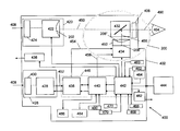
- FIG. 3 is a block diagram of an optically fused night vision monocular.
- FIG. 4 is a block diagram of an optically fused night vision binocular.
- FIG. 5 is a block diagram detailing interconnections between blocks shown in the optically fused night vision monocular of FIG. 3 .
- FIG. 3 is a block diagram of a first optically fused night vision system configured as a monocular 400 ;
- FIG. 4 is a block diagram of a second optically fused night vision system configured as a binocular 400 ′;
- FIG. 5 is a block diagram detailing interconnections between blocks shown in the optically fused night vision monocular of FIG. 3 consistent with the current disclosure.
- the system electronics and optics may be housed in a housing 402 , which can be mounted to a military helmet.
- An operator 404 looking through an eyepiece 406 within the housing 402 may be able to see a fused image 490 of a target 408 .
- Enclosed at least partially within the housing 402 may be an image intensifier (I 2 ) tube 422 , an infrared (IR) image detector 428 , for example a focal plane array (FPA), a combiner optics 432 , a display 434 , an illumination LED 436 , an analog circuit card assembly 438 , a digital circuit card assembly 440 , and a power circuit card assembly 442 .
- Suitable I 2 tubes 422 may be Generation HI tubes and are available from L-3 Communication Corporation and ITT.
- the focal plane array may be a U7000J from DRS.
- Other image detectors including near infrared electron bombarded active pixel sensors and short wave InGaAs arrays operating in other wavelengths, may be used without departing from this disclosure. Image detectors operating in the same wavelength may be used together.
- Information from the I 2 tube 422 and the IR image detector 428 may be fused together for viewing by an operator through the one or more eyepieces 406 .
- the eyepiece(s) 406 have one or more ocular lenses for magnifying and/or focusing the fused image.
- the I 2 tube 422 may be configured to process information in a first range of wavelengths (the visible portion of the electromagnetic spectrum from 400 nm to 900 nm) and the IR image detector 428 may be configured to process information in a second range of wavelengths (7,000 nm-14,000 nm).
- the I 2 tube 422 may have an objective focus 424 and the IR image detector 428 may have an objective focus 426 .
- the analog circuit card assembly 438 , the digital circuit card assembly 440 , and the power circuit card assembly 442 may be combined on a single flexible circuit assembly 446 .
- the display 434 may be a yellow monochrome organic light emitting diode (OLED) microdisplay available from eMagin Corp. as part no. EMA-100116.
- OLED organic light emitting diode
- the fusion night vision system 400 , 400 ′ may be powered by a separate and removably disconnectable battery pack 444 .
- Scene information 450 from the image intensifier tube 422 may be directed into optics 432 , for example a partially reflective beam combiner and information 452 from the image detector 428 may be directed into the system electronics on the analog circuit card assembly 438 .
- An analog video out signal 454 from the analog circuit card assembly 438 may be inputted into the display 434 .
- a serial bus 458 coupled to the digital circuit card assembly 440 may control the size, resolution, and offset of the display 434 .
- An output 456 from the display 434 may be directed through a first optical element 108 (see FIG. 1 ), for example a lens having a curved input and curved output surface, towards the image combiner 432 and then the fused image 490 is directed towards the operator 404 .
- the first optical element 108 may be aligned with the display 492 .
- a second optical element 106 may be disposed between an output image plane 202 of the image intensifier tube 422 and the image combiner 432 .
- an optical element 208 for example a glass or fiber optic bundle may be disposed between the display 434 and the image combiner 432 .
- the optical element 208 may be aligned with the display 492 and then coupled to the display with an adhesive.
- the optical element 208 may be have a generally flat input surface 208 ′ and a curved output surface 208 ′′.
- the curved output surface 208 ′′ may have a concave shape that cooperates with the curved output image plane 202 of the image intensifier tube 422 to improve viewability of the fused image as the eyepiece 406 is moved relative to the optic 432 .
- the output surface 208 ′′ may have a radius of curvature similar to the output surface 202 of the image intensifier tube 422 .
- the eyepiece 406 may be moved relative to the optic 432 in fusion night vision system 400 , 400 ′ to provide diopter adjustment to accommodate vision corrections unique to each user without compromising precision registration between the two images (from the display 434 and the output of the image intensifier tube 422 ). If both the image from the image intensifier tube and the image detector are to be affected identically by diopter adjustment, they must have identical effective focal length and identical distortion curves.
- the system can achieve similarly shaped image planes and improve viewability of the fused image as diopter adjustments are made.
- the fiber bundle is shown with a flat display and an image intensifier tube having a curved output image plane, the bundle can be used with any system having two or more image planes having differing physical geometries.
- the bundle may be used even if the two image planes do not need to be the exact same shape, rather it can be used with any image plane that needs to be modified from its original geometry. No additional ( 106 and 108 ) optical elements may be required in this embodiment.
- the optical element may be used in a system with an image intensifier and a display for displaying received digital information, for example digital map or target location information, instead of scene information from a detector and the combined image is the digital information overlayed on the scene information.
- received digital information for example digital map or target location information
- the fusion night vision system 400 , 400 ′ may have a plurality of user actuatable actuators including illumination LED actuator 460 , power on/off actuator 462 , stand-by actuator 464 , increase perceived mix of thermal to I 2 information actuator 466 , increase perceived mix of I 2 to thermal information actuator 468 , brightness down actuator 470 , brightness up actuator 472 , and thermal mode select actuator 480 .
- the actuators may employ a silicone overlay over tactile dome switches.
- the overlay may be coupled to the housing 402 to seal out moisture and particulates and the dome switches may be coupled to a processor.
- the increase perceived mix of thermal to I 2 information actuator 466 and the increase perceived mix of I 2 to thermal information actuator 468 may be fixed together and rotatable about a pivot.
- Rotation of the combined actuator in a first rotational direction increases the perceived mix of information in the eyepiece from the I 2 channel and rotation of the actuator in a second rotational direction increases the perceived mix of information in the eyepiece from the thermal channel.
- the increase or decrease in the perceived mix of information in the eyepiece from the I 2 channel can be changed continuously (ramp) or in discrete steps by the processor.
- the illumination LED actuator 460 may turn illumination LED 436 on and off.
- a single actuation of the illumination LED actuator 460 may turn the illuminating LED 436 on as long as the actuator 460 is actuated and a double tap (two actuations within a short period of time, for example 500 msec, may cause the illuminating LED 436 to latch on.
- a subsequent actuation of illumination LED actuator 460 may turn the illuminating LED 436 off.
- Stand-by actuator 464 may switch the system 400 to a lower power usage state without turning the system 400 , 400 ′ off.
- the thermal mode select actuator 480 allows the user to reverse the polarity of the image i.e.
- the fusion night vision systems 400 , 400 ′ may also have a low battery signal generator 482 .
- the low battery signal generator 482 may generate a visible or an audible signal to the operator to signal that the batteries in the battery pack 444 are low. Alternatively, the low battery signal may be displayed in the display 434 .
- the fusion night vision systems 400 , 400 ′ may also have a programming port 484 and a digital data port 486 for transferring data. Alternatively, the system 400 may utilize scroll actuators as discussed in relation to FIG. 3 .
- the fusion night vision systems 400 , 400 ′ may be called upon by the operator 404 to view the target 408 in a variety of adverse conditions, for example in very low light conditions, through smoke or heavy fog, and sand storms. In each of these conditions the operator may wish to rely more heavily on the image intensifier 422 than the image detector 428 and in other conditions the user may wish to rely more heavily on the image detector 428 than the image intensifier 422 .
- the increase perceived mix of thermal to I 2 information actuator 466 and the increase perceived mix of I 2 to thermal information I 2 image actuator 468 may be actuated to adjust the perceived mix of information from the image intensifier 422 and the image detector 428 viewable through the eyepiece(s) 406 , while generally maintaining the brightness of the display 434 .
- the viewable image contains generally 100% image intensification information
- the viewable image contains generally 100% thermal information
- the power circuit card assembly 442 controls the mix of I 2 and thermal information to the eyepiece 406 .
- the actuators 466 , 468 may be coupled to a microcontroller on the power circuit card assembly 442 that controls the gain of the I 2 tube 428 and the contrast and brightness of the thermal image presented in display 434 .
- the microcontroller may control a digital potentiometer coupled to the gain control input of the I 2 tube.
- the increase or decrease may be ramped or stepped.
- the increase perceived mix of IR to I 2 information actuator 466 and the increase perceived mix of I 2 to IR information actuator 468 may be positioned on opposite ends of a rocker mechanism to prevent simultaneous actuation.
- Certain embodiments of the invention can be implemented in hardware, software, firmware, or a combination thereof.
- the filter circuit and/or the threshold comparator and clamp circuit are/is implemented in software or firmware that is stored in a memory and that is executable by a suitable instruction execution system.
- the circuits can be implemented with any or a combination of the following technologies, which are well known in the art: a discrete logic circuit(s) having logic gates for implementing logic functions upon data signals, an application specific integrated circuit (ASIC) having appropriate combinational logic gates, a programmable gate array(s) (PGA), a field programmable gate array (FPGA), etc.
- the display 434 may be a miniature flat panel display, more particularly; it may be a monochrome organic light emitting diode (OLED) microdisplay or a liquid crystal display (LCD).
- the focal plane array and imaging electronics may be a micro bolometer imager currently available from L-3 or DRS.
- Other detectors capable of processing scene information including a digital image intensification tube, a near infrared electron bombarded active pixel sensor, a short wave InGaAs array, a charged couple device, and a CMOS detector, may be used without departing from the invention.
Abstract
Description
Claims (10)
Priority Applications (1)
| Application Number | Priority Date | Filing Date | Title |
|---|---|---|---|
| US13/828,816 US9148579B1 (en) | 2005-07-01 | 2013-03-14 | Fusion night vision system |
Applications Claiming Priority (3)
| Application Number | Priority Date | Filing Date | Title |
|---|---|---|---|
| US11/173,234 US7307793B2 (en) | 2004-07-02 | 2005-07-01 | Fusion night vision system |
| US11/928,328 US7864432B2 (en) | 2005-07-01 | 2007-10-30 | Fusion night vision system |
| US13/828,816 US9148579B1 (en) | 2005-07-01 | 2013-03-14 | Fusion night vision system |
Publications (1)
| Publication Number | Publication Date |
|---|---|
| US9148579B1 true US9148579B1 (en) | 2015-09-29 |
Family
ID=40381746
Family Applications (4)
| Application Number | Title | Priority Date | Filing Date |
|---|---|---|---|
| US11/173,234 Active 2025-11-27 US7307793B2 (en) | 2004-07-02 | 2005-07-01 | Fusion night vision system |
| US11/928,328 Active 2026-07-14 US7864432B2 (en) | 2005-07-01 | 2007-10-30 | Fusion night vision system |
| US12/952,955 Abandoned US20110089325A1 (en) | 2005-07-01 | 2010-11-23 | Fusion night vision system |
| US13/828,816 Active 2033-09-16 US9148579B1 (en) | 2005-07-01 | 2013-03-14 | Fusion night vision system |
Family Applications Before (3)
| Application Number | Title | Priority Date | Filing Date |
|---|---|---|---|
| US11/173,234 Active 2025-11-27 US7307793B2 (en) | 2004-07-02 | 2005-07-01 | Fusion night vision system |
| US11/928,328 Active 2026-07-14 US7864432B2 (en) | 2005-07-01 | 2007-10-30 | Fusion night vision system |
| US12/952,955 Abandoned US20110089325A1 (en) | 2005-07-01 | 2010-11-23 | Fusion night vision system |
Country Status (1)
| Country | Link |
|---|---|
| US (4) | US7307793B2 (en) |
Cited By (9)
| Publication number | Priority date | Publication date | Assignee | Title |
|---|---|---|---|---|
| RU188216U1 (en) * | 2019-01-17 | 2019-04-03 | Акционерное общество "Московский завод "САПФИР" | Active Pulse Television Night Vision |
| RU197393U1 (en) * | 2020-01-22 | 2020-04-23 | Акционерное общество "Московский завод "САПФИР" | Vehicle night driving device |
| RU199901U1 (en) * | 2020-06-23 | 2020-09-25 | Акционерное общество "Московский завод "САПФИР" | Active pulse television night vision device for underwater surveillance |
| RU200925U1 (en) * | 2020-08-13 | 2020-11-19 | Акционерное общество "Московский завод "САПФИР" | Three-channel pulsed laser illuminator |
| RU204472U1 (en) * | 2021-02-17 | 2021-05-26 | Акционерное общество "Московский завод "САПФИР" | Active pulse television night vision device with variable magnification |
| US11346938B2 (en) | 2019-03-15 | 2022-05-31 | Msa Technology, Llc | Safety device for providing output to an individual associated with a hazardous environment |
| RU211343U1 (en) * | 2022-01-17 | 2022-06-01 | Акционерное общество "Московский завод "САПФИР" | Active-pulse television night vision device based on a pulsed solid-state laser |
| WO2022123576A1 (en) * | 2020-12-09 | 2022-06-16 | Elbit Systems Ltd. | An eyepiece for night vision devices capable of injecting a synthetic image with a single optical correction mechanism |
| US11493771B2 (en) | 2019-10-04 | 2022-11-08 | Rockwell Collins, Inc. | NVIS compatible head-up display combiner alignment detector |
Families Citing this family (149)
| Publication number | Priority date | Publication date | Assignee | Title |
|---|---|---|---|---|
| US7427758B2 (en) | 2003-05-28 | 2008-09-23 | Opto-Knowledge Systems, Inc. | Cryogenically cooled adjustable apertures for infra-red cameras |
| US7307793B2 (en) * | 2004-07-02 | 2007-12-11 | Insight Technology, Inc. | Fusion night vision system |
| EP1831657B1 (en) * | 2004-12-03 | 2018-12-05 | Fluke Corporation | Method for a visible light and ir combined image camera |
| US7535002B2 (en) * | 2004-12-03 | 2009-05-19 | Fluke Corporation | Camera with visible light and infrared image blending |
| US8531562B2 (en) | 2004-12-03 | 2013-09-10 | Fluke Corporation | Visible light and IR combined image camera with a laser pointer |
| US7492962B2 (en) * | 2005-08-25 | 2009-02-17 | Delphi Technologies, Inc. | System or method for enhancing an image |
| US20070228259A1 (en) * | 2005-10-20 | 2007-10-04 | Hohenberger Roger T | System and method for fusing an image |
| US7634157B1 (en) | 2006-03-23 | 2009-12-15 | Flir Systems, Inc. | Infrared and near-infrared camera hyperframing |
| US7606484B1 (en) * | 2006-03-23 | 2009-10-20 | Flir Systems, Inc. | Infrared and near-infrared camera hyperframing |
| US7805020B2 (en) * | 2006-07-25 | 2010-09-28 | Itt Manufacturing Enterprises, Inc. | Motion compensated image registration for overlaid/fused video |
| US7887234B2 (en) * | 2006-10-20 | 2011-02-15 | Siemens Corporation | Maximum blade surface temperature estimation for advanced stationary gas turbines in near-infrared (with reflection) |
| US8189938B2 (en) * | 2007-01-10 | 2012-05-29 | L-3 Insight Technology Incorporated | Enhanced infrared imaging system |
| US8072469B2 (en) * | 2007-04-03 | 2011-12-06 | L-3 Communications Insight Technology Incorporated | Fusion night vision system with parallax correction |
| US8164813B1 (en) | 2007-06-16 | 2012-04-24 | Opto-Knowledge Systems, Inc. | Non-circular continuous variable aperture or shutter for infrared cameras |
| US7809258B2 (en) * | 2007-07-06 | 2010-10-05 | Flir Systems Ab | Camera and method for use with camera |
| US9557140B2 (en) * | 2008-01-24 | 2017-01-31 | Aimpoint Ab | Sight |
| US8970677B2 (en) * | 2008-02-19 | 2015-03-03 | Bae Systems Information And Electronic Systems Integration Inc. | Focus actuated vergence |
| US8314716B2 (en) * | 2008-03-27 | 2012-11-20 | Siemens Industry, Inc. | Use of OLED technology in HVAC sensors |
| US8687844B2 (en) | 2008-06-13 | 2014-04-01 | Raytheon Company | Visual detection system for identifying objects within region of interest |
| US9426389B1 (en) | 2008-06-14 | 2016-08-23 | Vectronix Inc. | Second imaging device adaptable for use with first imaging device and method for using same |
| US20100001187A1 (en) * | 2008-07-02 | 2010-01-07 | Rex Systems, Inc. | Headwear-mountable situational awareness unit |
| US7924312B2 (en) * | 2008-08-22 | 2011-04-12 | Fluke Corporation | Infrared and visible-light image registration |
| US9952664B2 (en) | 2014-01-21 | 2018-04-24 | Osterhout Group, Inc. | Eye imaging in head worn computing |
| US9400390B2 (en) | 2014-01-24 | 2016-07-26 | Osterhout Group, Inc. | Peripheral lighting for head worn computing |
| US9715112B2 (en) | 2014-01-21 | 2017-07-25 | Osterhout Group, Inc. | Suppression of stray light in head worn computing |
| US9229233B2 (en) | 2014-02-11 | 2016-01-05 | Osterhout Group, Inc. | Micro Doppler presentations in head worn computing |
| US9298007B2 (en) | 2014-01-21 | 2016-03-29 | Osterhout Group, Inc. | Eye imaging in head worn computing |
| US20150205111A1 (en) | 2014-01-21 | 2015-07-23 | Osterhout Group, Inc. | Optical configurations for head worn computing |
| US9965681B2 (en) | 2008-12-16 | 2018-05-08 | Osterhout Group, Inc. | Eye imaging in head worn computing |
| EP2374038A1 (en) * | 2008-12-19 | 2011-10-12 | BAE Systems PLC | Display system |
| US8336777B1 (en) * | 2008-12-22 | 2012-12-25 | Pantuso Francis P | Covert aiming and imaging devices |
| US9442019B2 (en) * | 2008-12-26 | 2016-09-13 | Fluke Corporation | Infrared imaging probe |
| DE102009009360B4 (en) * | 2009-02-18 | 2012-01-19 | Dräger Safety AG & Co. KGaA | Thermal camera |
| US8749635B2 (en) * | 2009-06-03 | 2014-06-10 | Flir Systems, Inc. | Infrared camera systems and methods for dual sensor applications |
| US10044946B2 (en) | 2009-06-03 | 2018-08-07 | Flir Systems Ab | Facilitating analysis and interpretation of associated visible light and infrared (IR) image information |
| US9843743B2 (en) * | 2009-06-03 | 2017-12-12 | Flir Systems, Inc. | Infant monitoring systems and methods using thermal imaging |
| US9335536B2 (en) * | 2011-06-20 | 2016-05-10 | Yoachim C. Russ | Visual target acquisition scope system |
| AU2011285873B2 (en) | 2010-08-04 | 2015-07-09 | Trijicon, Inc. | Optical Sight |
| US8836793B1 (en) | 2010-08-13 | 2014-09-16 | Opto-Knowledge Systems, Inc. | True color night vision (TCNV) fusion |
| US8767053B2 (en) * | 2010-08-26 | 2014-07-01 | Stmicroelectronics, Inc. | Method and apparatus for viewing stereoscopic video material simultaneously with multiple participants |
| US8743206B2 (en) * | 2010-08-31 | 2014-06-03 | Exelis, Inc. | Indicator systems in beam combiner assemblies |
| US9069172B1 (en) | 2010-09-15 | 2015-06-30 | Roland Morley | Multi-mode sight |
| US20120098971A1 (en) * | 2010-10-22 | 2012-04-26 | Flir Systems, Inc. | Infrared binocular system with dual diopter adjustment |
| US9618746B2 (en) | 2010-11-19 | 2017-04-11 | SA Photonics, Inc. | High resolution wide field of view digital night vision system |
| US8736967B1 (en) | 2010-11-19 | 2014-05-27 | SA Photonics, Inc. | Anamorphic eyepiece |
| US8755597B1 (en) * | 2011-02-24 | 2014-06-17 | Exelis, Inc. | Smart fusion of visible and infrared image data |
| IN2012DE00668A (en) | 2011-03-09 | 2015-08-21 | Bae Systems Information & Electronic Systems Integration Inc | |
| US8860800B2 (en) | 2011-03-31 | 2014-10-14 | Flir Systems, Inc. | Boresight alignment station |
| US9509924B2 (en) * | 2011-06-10 | 2016-11-29 | Flir Systems, Inc. | Wearable apparatus with integrated infrared imaging module |
| US8981295B2 (en) | 2011-07-18 | 2015-03-17 | Kenneth JAMISON | Night vision device with display of ancillary environmental information |
| US9204062B2 (en) | 2011-08-24 | 2015-12-01 | Fluke Corporation | Thermal imaging camera with range detection |
| US20130240733A1 (en) * | 2011-08-25 | 2013-09-19 | Bae Systems Information And Electronic Systems Integration Inc. | Modular multi-use thermal imaging system |
| KR101709282B1 (en) * | 2011-11-15 | 2017-02-24 | 삼성전자주식회사 | Image sensor, operation method therof,and apparatuses including the same |
| EP2634747A1 (en) * | 2012-02-29 | 2013-09-04 | Flir Systems AB | A method and system for projecting a visible representation of infrared radiation |
| US8824828B1 (en) | 2012-03-28 | 2014-09-02 | Exelis, Inc. | Thermal V-curve for fusion image declutter |
| US10782097B2 (en) * | 2012-04-11 | 2020-09-22 | Christopher J. Hall | Automated fire control device |
| US9389425B2 (en) | 2012-04-18 | 2016-07-12 | Kopin Corporation | Viewer with display overlay |
| US9323061B2 (en) | 2012-04-18 | 2016-04-26 | Kopin Corporation | Viewer with display overlay |
| US9373277B2 (en) | 2012-06-21 | 2016-06-21 | Bae Systems Information And Electronic Systems Integration Inc. | Extending dynamic range of a display |
| MA20150368A1 (en) * | 2012-07-17 | 2015-10-30 | Aselsan Elektronik Sanayi Ve Ticaret Anonim Sirketi | Thermal camera |
| US9407817B2 (en) * | 2012-08-07 | 2016-08-02 | Manufacturing Techniques, Inc. | Imager device for fusing an image from multiple sources |
| US8860831B1 (en) * | 2013-02-21 | 2014-10-14 | Exelis, Inc. | Brightness tracking light sensor |
| US9443335B2 (en) * | 2013-09-18 | 2016-09-13 | Blackberry Limited | Using narrow field of view monochrome camera for producing a zoomed image |
| CN104601913B (en) * | 2013-10-30 | 2017-11-03 | 北京莫高丝路文化发展有限公司 | Ball curtain multi-channel edge fusion method |
| US11103122B2 (en) | 2014-07-15 | 2021-08-31 | Mentor Acquisition One, Llc | Content presentation in head worn computing |
| US9746686B2 (en) | 2014-05-19 | 2017-08-29 | Osterhout Group, Inc. | Content position calibration in head worn computing |
| US9594246B2 (en) | 2014-01-21 | 2017-03-14 | Osterhout Group, Inc. | See-through computer display systems |
| US9829707B2 (en) | 2014-08-12 | 2017-11-28 | Osterhout Group, Inc. | Measuring content brightness in head worn computing |
| US20150228119A1 (en) | 2014-02-11 | 2015-08-13 | Osterhout Group, Inc. | Spatial location presentation in head worn computing |
| US11227294B2 (en) | 2014-04-03 | 2022-01-18 | Mentor Acquisition One, Llc | Sight information collection in head worn computing |
| US10254856B2 (en) | 2014-01-17 | 2019-04-09 | Osterhout Group, Inc. | External user interface for head worn computing |
| US10191279B2 (en) | 2014-03-17 | 2019-01-29 | Osterhout Group, Inc. | Eye imaging in head worn computing |
| US9841599B2 (en) | 2014-06-05 | 2017-12-12 | Osterhout Group, Inc. | Optical configurations for head-worn see-through displays |
| US9299194B2 (en) | 2014-02-14 | 2016-03-29 | Osterhout Group, Inc. | Secure sharing in head worn computing |
| US20160019715A1 (en) | 2014-07-15 | 2016-01-21 | Osterhout Group, Inc. | Content presentation in head worn computing |
| US9529195B2 (en) | 2014-01-21 | 2016-12-27 | Osterhout Group, Inc. | See-through computer display systems |
| US10649220B2 (en) | 2014-06-09 | 2020-05-12 | Mentor Acquisition One, Llc | Content presentation in head worn computing |
| US9939934B2 (en) | 2014-01-17 | 2018-04-10 | Osterhout Group, Inc. | External user interface for head worn computing |
| US9575321B2 (en) | 2014-06-09 | 2017-02-21 | Osterhout Group, Inc. | Content presentation in head worn computing |
| US10684687B2 (en) | 2014-12-03 | 2020-06-16 | Mentor Acquisition One, Llc | See-through computer display systems |
| US20150277118A1 (en) | 2014-03-28 | 2015-10-01 | Osterhout Group, Inc. | Sensor dependent content position in head worn computing |
| US9810906B2 (en) | 2014-06-17 | 2017-11-07 | Osterhout Group, Inc. | External user interface for head worn computing |
| US9671613B2 (en) | 2014-09-26 | 2017-06-06 | Osterhout Group, Inc. | See-through computer display systems |
| US9448409B2 (en) | 2014-11-26 | 2016-09-20 | Osterhout Group, Inc. | See-through computer display systems |
| US9651784B2 (en) | 2014-01-21 | 2017-05-16 | Osterhout Group, Inc. | See-through computer display systems |
| US11487110B2 (en) | 2014-01-21 | 2022-11-01 | Mentor Acquisition One, Llc | Eye imaging in head worn computing |
| US20150205135A1 (en) | 2014-01-21 | 2015-07-23 | Osterhout Group, Inc. | See-through computer display systems |
| US9766463B2 (en) | 2014-01-21 | 2017-09-19 | Osterhout Group, Inc. | See-through computer display systems |
| US9523856B2 (en) | 2014-01-21 | 2016-12-20 | Osterhout Group, Inc. | See-through computer display systems |
| US9753288B2 (en) | 2014-01-21 | 2017-09-05 | Osterhout Group, Inc. | See-through computer display systems |
| US9538915B2 (en) | 2014-01-21 | 2017-01-10 | Osterhout Group, Inc. | Eye imaging in head worn computing |
| US9836122B2 (en) | 2014-01-21 | 2017-12-05 | Osterhout Group, Inc. | Eye glint imaging in see-through computer display systems |
| US11737666B2 (en) | 2014-01-21 | 2023-08-29 | Mentor Acquisition One, Llc | Eye imaging in head worn computing |
| US9494800B2 (en) | 2014-01-21 | 2016-11-15 | Osterhout Group, Inc. | See-through computer display systems |
| US9811159B2 (en) | 2014-01-21 | 2017-11-07 | Osterhout Group, Inc. | Eye imaging in head worn computing |
| US11892644B2 (en) | 2014-01-21 | 2024-02-06 | Mentor Acquisition One, Llc | See-through computer display systems |
| US11669163B2 (en) | 2014-01-21 | 2023-06-06 | Mentor Acquisition One, Llc | Eye glint imaging in see-through computer display systems |
| US9846308B2 (en) | 2014-01-24 | 2017-12-19 | Osterhout Group, Inc. | Haptic systems for head-worn computers |
| US9401540B2 (en) | 2014-02-11 | 2016-07-26 | Osterhout Group, Inc. | Spatial location presentation in head worn computing |
| US20150241963A1 (en) | 2014-02-11 | 2015-08-27 | Osterhout Group, Inc. | Eye imaging in head worn computing |
| US9852545B2 (en) | 2014-02-11 | 2017-12-26 | Osterhout Group, Inc. | Spatial location presentation in head worn computing |
| US20160187651A1 (en) | 2014-03-28 | 2016-06-30 | Osterhout Group, Inc. | Safety for a vehicle operator with an hmd |
| WO2015157058A1 (en) * | 2014-04-07 | 2015-10-15 | Bae Systems Information & Electronic Systems Integration Inc. | Contrast based image fusion |
| US10015474B2 (en) | 2014-04-22 | 2018-07-03 | Fluke Corporation | Methods for end-user parallax adjustment |
| US9423842B2 (en) | 2014-09-18 | 2016-08-23 | Osterhout Group, Inc. | Thermal management for head-worn computer |
| US10853589B2 (en) | 2014-04-25 | 2020-12-01 | Mentor Acquisition One, Llc | Language translation with head-worn computing |
| US9672210B2 (en) | 2014-04-25 | 2017-06-06 | Osterhout Group, Inc. | Language translation with head-worn computing |
| US9651787B2 (en) | 2014-04-25 | 2017-05-16 | Osterhout Group, Inc. | Speaker assembly for headworn computer |
| EP3143468B1 (en) * | 2014-05-12 | 2019-04-10 | Gulfstream Aerospace Corporation | Advanced aircraft vision system utilizing multi-sensor gain scheduling |
| EP3146379A4 (en) | 2014-05-23 | 2018-01-24 | Nuviz, Inc. | Helmet mounted display |
| US10663740B2 (en) | 2014-06-09 | 2020-05-26 | Mentor Acquisition One, Llc | Content presentation in head worn computing |
| US20160033336A1 (en) * | 2014-07-30 | 2016-02-04 | Milwaukee Electric Tool Corporation | Thermal detection systems, methods, and devices |
| CN104299231B (en) * | 2014-09-26 | 2017-04-19 | 北京环境特性研究所 | Method and system for registering images of multiple sensors in real time |
| US9684172B2 (en) | 2014-12-03 | 2017-06-20 | Osterhout Group, Inc. | Head worn computer display systems |
| USD743963S1 (en) | 2014-12-22 | 2015-11-24 | Osterhout Group, Inc. | Air mouse |
| USD751552S1 (en) | 2014-12-31 | 2016-03-15 | Osterhout Group, Inc. | Computer glasses |
| USD753114S1 (en) | 2015-01-05 | 2016-04-05 | Osterhout Group, Inc. | Air mouse |
| US20160239985A1 (en) | 2015-02-17 | 2016-08-18 | Osterhout Group, Inc. | See-through computer display systems |
| US9651786B1 (en) | 2015-05-05 | 2017-05-16 | SA Photonics, Inc. | Systems and methods for augmented reality devices with light security |
| GB2570602B (en) * | 2015-06-18 | 2020-02-12 | Qioptiq Ltd | Parallax correction device and method in blended optical system for use over a range of temperatures |
| US10432840B2 (en) * | 2015-10-08 | 2019-10-01 | L-3 Communication-Insight Technology Division | Fusion night vision system |
| US10591728B2 (en) | 2016-03-02 | 2020-03-17 | Mentor Acquisition One, Llc | Optical systems for head-worn computers |
| US10667981B2 (en) | 2016-02-29 | 2020-06-02 | Mentor Acquisition One, Llc | Reading assistance system for visually impaired |
| US10079983B2 (en) | 2016-03-01 | 2018-09-18 | Fluke Corporation | Compact camera |
| EP3516448B1 (en) | 2016-09-22 | 2022-08-24 | Lightforce USA, Inc., D/B/A/ Nightforce Optics | Optical targeting information projection system for weapon system aiming scopes and related systems |
| CN106630688B (en) * | 2016-11-15 | 2019-07-05 | 福耀玻璃工业集团股份有限公司 | It being capable of electrically heated new line display laminated glass |
| MX2019009307A (en) | 2017-02-06 | 2020-01-20 | Sheltered Wings Inc D/B/A Vortex Optics | Viewing optic with an integrated display system. |
| GB2601644B (en) | 2017-04-28 | 2023-02-08 | FLIR Belgium BVBA | Video and image chart fusion systems and methods |
| US10126099B1 (en) | 2017-05-11 | 2018-11-13 | Steiner Eoptics, Inc. | Thermal reflex sight |
| US11378801B1 (en) | 2017-05-25 | 2022-07-05 | Vision Products, Llc | Wide field of view night vision system |
| TWI634348B (en) * | 2017-07-26 | 2018-09-01 | 英屬維京群島商宇博先進股份有限公司 | Wearable device with thermal imaging function |
| US11675180B2 (en) | 2018-01-12 | 2023-06-13 | Sheltered Wings, Inc. | Viewing optic with an integrated display system |
| CN112543858A (en) | 2018-04-20 | 2021-03-23 | 夏尔特银斯公司D.B.A.涡流光学 | Viewing optic with direct active reticle collimation |
| JP7210199B2 (en) * | 2018-09-20 | 2023-01-23 | キヤノン株式会社 | IMAGING DEVICE, CONTROL METHOD, COMPUTER PROGRAM, AND STORAGE MEDIUM |
| JP2022517661A (en) | 2019-01-18 | 2022-03-09 | シェルタード ウィングス インコーポレイテッド | Observation optics with bullet counter system |
| FR3097658B1 (en) * | 2019-06-20 | 2022-07-08 | Photonis France | VISION DEVICE OFFERING NIGHT VISION AND DIRECT VISION OF A SURROUNDING SCENE |
| DE102020100929A1 (en) | 2020-01-16 | 2021-07-22 | Vhf Elektronik Gmbh | Thermal imaging or processing methods |
| US11204649B2 (en) | 2020-01-30 | 2021-12-21 | SA Photonics, Inc. | Head-mounted display with user-operated control |
| US10848705B1 (en) * | 2020-02-20 | 2020-11-24 | New Pocket Device Corp. | Night-viewing device |
| US11402273B2 (en) * | 2020-03-27 | 2022-08-02 | Ecb Consulting Llc | Systems and approaches for improving accuracy of temperature measurements using thermal imaging |
| CN111766697B (en) * | 2020-09-03 | 2020-12-01 | 北京中星时代科技有限公司 | Fusion type telescope based on infrared and shimmer formation of image |
| US11516385B2 (en) * | 2020-12-09 | 2022-11-29 | Microsoft Technology Licensing, Llc | Dynamic quality proxy plural camera image blending |
| DE102021107156B3 (en) | 2021-02-02 | 2022-05-12 | Vhf Elektronik Gmbh | Aiming and/or observation device with image overlay |
| EP4143521A1 (en) * | 2021-02-02 | 2023-03-08 | Vected Gmbh | Aiming and/or monitoring device with image superimposition |
| FR3119671B1 (en) | 2021-02-10 | 2023-12-08 | Bertin Technologies Sa | Observation system and method |
| CN113432839B (en) * | 2021-06-09 | 2022-09-16 | 北方夜视技术股份有限公司 | System and method for comprehensively testing image quality of low-light-level image intensifier |
| DE102022200901B3 (en) | 2022-01-27 | 2023-05-25 | Carl Zeiss Ag | Electro-optical observation device |
| GB2616061A (en) * | 2022-02-28 | 2023-08-30 | Uab Yukon Advanced Optics Worldwide | Observation device |
| CN116993729B (en) * | 2023-09-26 | 2024-03-29 | 南京铂航电子科技有限公司 | Night vision device imaging system and method based on second harmonic |
Citations (5)
| Publication number | Priority date | Publication date | Assignee | Title |
|---|---|---|---|---|
| US4653879A (en) * | 1985-03-01 | 1987-03-31 | Fjw Industries, Inc. | Compact see-through night vision goggles |
| US4961626A (en) * | 1989-02-21 | 1990-10-09 | United Techologies Corporation | Direct incorporation of night vision in a helmet mounted display |
| US6259088B1 (en) * | 1999-06-24 | 2001-07-10 | The United States Of America As Represented By The Secretary Of The Army | Image intensifier tube with curved components |
| US20040042086A1 (en) * | 2002-06-05 | 2004-03-04 | Litton Systems, Inc. | Enhanced night vision goggle assembly |
| US20070235634A1 (en) * | 2004-07-02 | 2007-10-11 | Ottney Joseph C | Fusion night vision system |
Family Cites Families (36)
| Publication number | Priority date | Publication date | Assignee | Title |
|---|---|---|---|---|
| US4002405A (en) * | 1975-04-03 | 1977-01-11 | Curt Stahl | Variable speed control for zooming |
| USD248860S (en) | 1976-03-11 | 1978-08-08 | International Telephone & Telegraph Corporation | Night vision pocketscope |
| EP0066402B1 (en) | 1981-05-29 | 1985-09-11 | Gec Avionics Limited | Night vision goggles |
| US4707595A (en) | 1985-01-30 | 1987-11-17 | Meyers Brad E | Invisible light beam projector and night vision system |
| US4720871A (en) * | 1986-06-13 | 1988-01-19 | Hughes Aircraft Company | Digital image convolution processor method and apparatus |
| US4751571A (en) | 1987-07-29 | 1988-06-14 | General Electric Company | Composite visible/thermal-infrared imaging apparatus |
| AU2905489A (en) | 1987-10-27 | 1989-05-23 | Night Vision Partnership | Compact see-through night vision goggles |
| US4915487A (en) | 1989-02-01 | 1990-04-10 | Systems Research Laboratories | Heads up display for night vision goggle |
| US4991183A (en) | 1990-03-02 | 1991-02-05 | Meyers Brad E | Target illuminators and systems employing same |
| US5035472A (en) | 1990-06-20 | 1991-07-30 | The United States Of America As Represented By The Secretary Of The Army | Integrated multispectral man portable weapon sight |
| US5229598A (en) | 1992-01-29 | 1993-07-20 | Night Vision General Partnership | Night vision goggles having enlarged field of view and interchangeable optics |
| US5254852A (en) | 1992-05-28 | 1993-10-19 | Night Vision General Partnership | Helmet-mounted night vision system and secondary imager |
| US5270545A (en) | 1992-11-30 | 1993-12-14 | Itt Corporation | External compass module for night vision devices |
| US5416315A (en) | 1994-01-24 | 1995-05-16 | Night Vision General Partnership | Visor-mounted night vision visor |
| US6219250B1 (en) | 1996-04-03 | 2001-04-17 | Itt Manufacturing Enterprises | Night vision binoculars |
| US6061182A (en) | 1996-11-21 | 2000-05-09 | Vectop Ltd. | Combiner for superimposing a display image on to an image of an external scene |
| US6075644A (en) | 1996-12-20 | 2000-06-13 | Night Vision General Partnership | Panoramic night vision goggles |
| US5844723A (en) * | 1997-04-11 | 1998-12-01 | Blue Sky Research | Laser diode assembly including a carrier-mounted crossed pair of cylindrical microlenses |
| US6081094A (en) | 1997-07-17 | 2000-06-27 | Itt Manufacturing Enterprises, Inc. | Clip-on power source for an aviator's night vision imaging system |
| US6456497B1 (en) | 1998-03-12 | 2002-09-24 | Itt Manufacturing Enterprises, Inc. | Night vision binoculars |
| US5943174A (en) | 1998-06-16 | 1999-08-24 | Itt Manufacturing Enterprises, Inc. | Night vision monocular device |
| US6288386B1 (en) | 1998-10-28 | 2001-09-11 | Itt Manufacturing Enterprises Inc. | Circuit having a flexible printed circuit board for electronically controlling a night vision device and night vision device including the same |
| US6232602B1 (en) | 1999-03-05 | 2001-05-15 | Flir Systems, Inc. | Enhanced vision system sensitive to infrared radiation |
| US6088165A (en) | 1999-04-28 | 2000-07-11 | Itt Manufacturing Enterprises | Enhanced night vision device |
| US7053928B1 (en) | 2000-03-20 | 2006-05-30 | Litton Systems, Inc. | Method and system for combining multi-spectral images of a scene |
| US6911652B2 (en) | 2000-03-22 | 2005-06-28 | Jonathan A. Walkenstein | Low light imaging device |
| US7345277B2 (en) * | 2000-08-09 | 2008-03-18 | Evan Zhang | Image intensifier and LWIR fusion/combination system |
| US6646799B1 (en) | 2000-08-30 | 2003-11-11 | Science Applications International Corporation | System and method for combining multiple energy bands to improve scene viewing |
| US6462894B1 (en) | 2001-02-16 | 2002-10-08 | Insight Technology, Inc. | Monocular mounting for four-tube panoramic night vision goggle having multi-function adjustment control |
| US6493137B1 (en) | 2001-02-16 | 2002-12-10 | Insight Technology, Inc. | Monocular mounting for multi-channel panoramic night vision goggle having a hot shoe connector |
| US6469828B2 (en) | 2001-02-16 | 2002-10-22 | Insight Technology, Inc. | Panoramic night vision goggle having multi-channel monocular assemblies with a modified eyepiece |
| US6462867B2 (en) | 2001-02-16 | 2002-10-08 | Insight Technology, Inc. | Monocular mounting for multi-channel panoramic night vision goggle having an angled mounting shoe |
| US6687053B1 (en) | 2001-09-27 | 2004-02-03 | Itt Manufacturing Enterprises, Inc. | Binocular device and method utilizing monocular devices |
| US6560029B1 (en) | 2001-12-21 | 2003-05-06 | Itt Manufacturing Enterprises, Inc. | Video enhanced night vision goggle |
| US6662370B1 (en) | 2002-01-11 | 2003-12-16 | Itt Manufacturing Enterprises, Inc. | Night vision device helmet mount |
| US6798578B1 (en) | 2002-06-06 | 2004-09-28 | Litton Systems, Inc. | Integrated display image intensifier assembly |
-
2005
- 2005-07-01 US US11/173,234 patent/US7307793B2/en active Active
-
2007
- 2007-10-30 US US11/928,328 patent/US7864432B2/en active Active
-
2010
- 2010-11-23 US US12/952,955 patent/US20110089325A1/en not_active Abandoned
-
2013
- 2013-03-14 US US13/828,816 patent/US9148579B1/en active Active
Patent Citations (5)
| Publication number | Priority date | Publication date | Assignee | Title |
|---|---|---|---|---|
| US4653879A (en) * | 1985-03-01 | 1987-03-31 | Fjw Industries, Inc. | Compact see-through night vision goggles |
| US4961626A (en) * | 1989-02-21 | 1990-10-09 | United Techologies Corporation | Direct incorporation of night vision in a helmet mounted display |
| US6259088B1 (en) * | 1999-06-24 | 2001-07-10 | The United States Of America As Represented By The Secretary Of The Army | Image intensifier tube with curved components |
| US20040042086A1 (en) * | 2002-06-05 | 2004-03-04 | Litton Systems, Inc. | Enhanced night vision goggle assembly |
| US20070235634A1 (en) * | 2004-07-02 | 2007-10-11 | Ottney Joseph C | Fusion night vision system |
Cited By (10)
| Publication number | Priority date | Publication date | Assignee | Title |
|---|---|---|---|---|
| RU188216U1 (en) * | 2019-01-17 | 2019-04-03 | Акционерное общество "Московский завод "САПФИР" | Active Pulse Television Night Vision |
| US11346938B2 (en) | 2019-03-15 | 2022-05-31 | Msa Technology, Llc | Safety device for providing output to an individual associated with a hazardous environment |
| US11493771B2 (en) | 2019-10-04 | 2022-11-08 | Rockwell Collins, Inc. | NVIS compatible head-up display combiner alignment detector |
| RU197393U1 (en) * | 2020-01-22 | 2020-04-23 | Акционерное общество "Московский завод "САПФИР" | Vehicle night driving device |
| RU199901U1 (en) * | 2020-06-23 | 2020-09-25 | Акционерное общество "Московский завод "САПФИР" | Active pulse television night vision device for underwater surveillance |
| RU200925U1 (en) * | 2020-08-13 | 2020-11-19 | Акционерное общество "Московский завод "САПФИР" | Three-channel pulsed laser illuminator |
| WO2022123576A1 (en) * | 2020-12-09 | 2022-06-16 | Elbit Systems Ltd. | An eyepiece for night vision devices capable of injecting a synthetic image with a single optical correction mechanism |
| IL279343A (en) * | 2020-12-09 | 2022-07-01 | Elbit Systems Ltd | An eyepiece for night vision devices capable of injecting a synthetic image with a single optical correction mechanism |
| RU204472U1 (en) * | 2021-02-17 | 2021-05-26 | Акционерное общество "Московский завод "САПФИР" | Active pulse television night vision device with variable magnification |
| RU211343U1 (en) * | 2022-01-17 | 2022-06-01 | Акционерное общество "Московский завод "САПФИР" | Active-pulse television night vision device based on a pulsed solid-state laser |
Also Published As
| Publication number | Publication date |
|---|---|
| US20090051760A1 (en) | 2009-02-26 |
| US7307793B2 (en) | 2007-12-11 |
| US7864432B2 (en) | 2011-01-04 |
| US20070235634A1 (en) | 2007-10-11 |
| US20110089325A1 (en) | 2011-04-21 |
Similar Documents
| Publication | Publication Date | Title |
|---|---|---|
| US9148579B1 (en) | Fusion night vision system | |
| US7158296B1 (en) | Vision system with eye dominance forced to fusion channel | |
| US7345277B2 (en) | Image intensifier and LWIR fusion/combination system | |
| US7541581B2 (en) | Clip-on infrared imager | |
| US7746551B2 (en) | Vision system with eye dominance forced to fusion channel | |
| US6476391B1 (en) | Infrared imaging system for advanced rescue vision system | |
| US20070228259A1 (en) | System and method for fusing an image | |
| US7813037B2 (en) | Day/night-vision device | |
| US11206341B2 (en) | Fusion night vision system | |
| EP3401631B1 (en) | Thermal reflex sight | |
| US20190018238A1 (en) | Multi-wavelength head up display systems and methods | |
| US8368023B2 (en) | Optical bypass device | |
| US7459684B2 (en) | Long-wavelength infra-red night vision goggles | |
| US9191585B2 (en) | Modular night-vision system with fused optical sensors | |
| US11550139B2 (en) | Night-vision optical device with automatic infrared-cut function | |
| US9426389B1 (en) | Second imaging device adaptable for use with first imaging device and method for using same | |
| TWI660197B (en) | Magnifying optical device | |
| GB2538256A (en) | Optical data insertion device | |
| Zhou | Synthesized night vision goggle | |
| JPH08503789A (en) | Optical visual device |
Legal Events
| Date | Code | Title | Description |
|---|---|---|---|
| AS | Assignment |
Owner name: L-3 COMMUNICATIONS CORPORATION, WARRIOR SYSTEMS DI Free format text: ASSIGNMENT OF ASSIGNORS INTEREST;ASSIGNOR:SCHWARTZ, SHELDON;REEL/FRAME:030003/0173 Effective date: 20130314 |
|
| STCF | Information on status: patent grant |
Free format text: PATENTED CASE |
|
| MAFP | Maintenance fee payment |
Free format text: PAYMENT OF MAINTENANCE FEE, 4TH YEAR, LARGE ENTITY (ORIGINAL EVENT CODE: M1551); ENTITY STATUS OF PATENT OWNER: LARGE ENTITY Year of fee payment: 4 |
|
| MAFP | Maintenance fee payment |
Free format text: PAYMENT OF MAINTENANCE FEE, 8TH YEAR, LARGE ENTITY (ORIGINAL EVENT CODE: M1552); ENTITY STATUS OF PATENT OWNER: LARGE ENTITY Year of fee payment: 8 |