US8854470B2 - Vision-based augmented reality system using invisible marker - Google Patents
Vision-based augmented reality system using invisible marker Download PDFInfo
- Publication number
- US8854470B2 US8854470B2 US14/187,110 US201414187110A US8854470B2 US 8854470 B2 US8854470 B2 US 8854470B2 US 201414187110 A US201414187110 A US 201414187110A US 8854470 B2 US8854470 B2 US 8854470B2
- Authority
- US
- United States
- Prior art keywords
- ray camera
- infrared
- image
- visible
- ray
- Prior art date
- Legal status (The legal status is an assumption and is not a legal conclusion. Google has not performed a legal analysis and makes no representation as to the accuracy of the status listed.)
- Expired - Fee Related
Links
Images


Classifications
-
- G—PHYSICS
- G06—COMPUTING; CALCULATING OR COUNTING
- G06T—IMAGE DATA PROCESSING OR GENERATION, IN GENERAL
- G06T15/00—3D [Three Dimensional] image rendering
-
- G—PHYSICS
- G06—COMPUTING; CALCULATING OR COUNTING
- G06T—IMAGE DATA PROCESSING OR GENERATION, IN GENERAL
- G06T19/00—Manipulating 3D models or images for computer graphics
- G06T19/006—Mixed reality
-
- G—PHYSICS
- G06—COMPUTING; CALCULATING OR COUNTING
- G06T—IMAGE DATA PROCESSING OR GENERATION, IN GENERAL
- G06T17/00—Three dimensional [3D] modelling, e.g. data description of 3D objects
-
- G—PHYSICS
- G06—COMPUTING; CALCULATING OR COUNTING
- G06T—IMAGE DATA PROCESSING OR GENERATION, IN GENERAL
- G06T5/00—Image enhancement or restoration
- G06T5/50—Image enhancement or restoration by the use of more than one image, e.g. averaging, subtraction
-
- G—PHYSICS
- G06—COMPUTING; CALCULATING OR COUNTING
- G06T—IMAGE DATA PROCESSING OR GENERATION, IN GENERAL
- G06T7/00—Image analysis
- G06T7/20—Analysis of motion
-
- G—PHYSICS
- G06—COMPUTING; CALCULATING OR COUNTING
- G06T—IMAGE DATA PROCESSING OR GENERATION, IN GENERAL
- G06T7/00—Image analysis
- G06T7/70—Determining position or orientation of objects or cameras
- G06T7/73—Determining position or orientation of objects or cameras using feature-based methods
-
- H—ELECTRICITY
- H04—ELECTRIC COMMUNICATION TECHNIQUE
- H04N—PICTORIAL COMMUNICATION, e.g. TELEVISION
- H04N5/00—Details of television systems
- H04N5/30—Transforming light or analogous information into electric information
- H04N5/33—Transforming infrared radiation
-
- G—PHYSICS
- G06—COMPUTING; CALCULATING OR COUNTING
- G06T—IMAGE DATA PROCESSING OR GENERATION, IN GENERAL
- G06T2207/00—Indexing scheme for image analysis or image enhancement
- G06T2207/10—Image acquisition modality
- G06T2207/10016—Video; Image sequence
-
- G—PHYSICS
- G06—COMPUTING; CALCULATING OR COUNTING
- G06T—IMAGE DATA PROCESSING OR GENERATION, IN GENERAL
- G06T2207/00—Indexing scheme for image analysis or image enhancement
- G06T2207/10—Image acquisition modality
- G06T2207/10048—Infrared image
Definitions
- the present invention relates to an augmented reality system for real-time matching a virtual computer graphic (CG) image with a real image, and more particularly to a vision-based augmented reality system using an invisible marker, which indicates an invisible marker on a target object to be tracked, and rapidly and correctly tracks the target object by detecting the invisible marker, such that it rapidly implements correct augmented reality, obviates problems generated when a visible marker is used, and is applicable to a variety of application fields.
- CG virtual computer graphic
- the augmented reality is indicative of a user interface technique capable of correctly matching a virtual image generated by a computer with a real image viewed by a user.
- the above-mentioned augmented reality can provide a user with a higher reality and higher recognition accuracy.
- a method for correctly estimating the movement of a camera or a target object is of importance.
- a method for implementing the above-mentioned augmented reality generally includes the following first and second methods.
- the first method uses characteristics collected by objects existing in the real world, and is considered to be an ultimate purpose of the augmented reality field. However, if the number of characteristics collected by objects is a small number or an environment condition such as an illumination condition is unstable, performance is greatly deteriorated.
- the second method uses known markers, and is more stable than the above-mentioned first method. In this case, it is indicative of an object artificially inserted in the real world to correctly estimate the movement of a camera or a target object, such that it may hide other objects or may be unpleasant to the eye. Due to the above-mentioned problems, the augmented reality technologies using the known marker have limited application.
- the vision-based augmented reality system will hereinafter be described with reference to FIG. 1 .
- FIG. 1 is a conventional vision-based augmented reality system.
- the conventional vision-based augmented reality system includes a camera 11 for capturing a target object (TO) on which a visible marker (VM) is indicated; an image processor 12 for monitoring a position and attitude of the marker upon receiving a mark image indicated on the TO from the camera 11 , tracking a position and pose of the TO, and rendering a virtual image to a TO image such that it generates a new image; and an output unit 13 for displaying the image received from the image processor 12 on a screen.
- TO target object
- VM visible marker
- the above-mentioned augmented reality system uses the visible marker so that it correctly and rapidly implements the augmented reality.
- the marker is an artificial addition not present in the real world, such that the above-mentioned augmented reality system has a disadvantage in that the marker hides a desired target object or is unpleasant to the eye.
- the number of application fields of the above-mentioned augmented reality system using the visible marker is very limited.
- the present invention has been made in view of the above problems, and it is an object of the present invention to provide a vision-based augmented reality system using an invisible marker, which indicates an invisible marker on a target object to be tracked, and rapidly and correctly tracks the target object by detecting the invisible marker, such that it rapidly implements correct augmented reality, obviates problems generated when a visible marker is used, and is applicable to a variety of application fields.
- a vision-based augmented reality system using an invisible marker comprising: a target object (TO) including an infrared marker (IM) drawn by an invisible infrared light-emitting material; a visible-ray camera for capturing an image of the TO; an infrared-ray camera for capturing an image of the IM included in the TO image; an optical axis converter for transmitting a visible ray received from the TO to the visible-ray camera, transmitting an infrared ray received from the TO to the infrared-ray camera, and allowing the infrared-ray camera and the visible-ray camera to have the same viewing point; an image processing system for receiving the infrared marker image from the infrared-ray camera, receiving the TO image from the visible-ray camera, separating the infrared marker image and the TO image from each other, real-time monitoring a position and pose of the IM associated with the infrared-ray camera, real
- the above-mentioned vision-based augmented reality system using the invisible marker indicates an invisible marker on a target object to be tracked, and rapidly and correctly tracks the target object by detecting the invisible marker. Therefore, the vision-based augmented reality system rapidly implements correct augmented reality, obviates problems generated when a visible marker is used, and is applicable to a variety of application fields.
- FIG. 1 is a block diagram illustrating a conventional vision-based augmented reality system
- FIG. 2 is a block diagram illustrating a vision-based augmented reality system according to the present invention
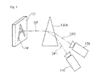
- FIG. 3 is a conceptual diagram illustrating a method for employing a prism acting as an optical axis converter according to the present invention
- FIG. 4 is a flow chart illustrating an image processing system according to the present invention.
- FIGS. 5 a and 5 b are exemplary images captured by a visible-ray camera or an infrared camera according to the present invention.
- FIG. 6 is an implementation example of the augmented reality according to the present invention.
- FIG. 2 is a block diagram illustrating a vision-based augmented reality system according to the present invention.
- the vision-based augmented reality system includes a Target Object (TO) to be tracked, a visible-ray camera 110 , an infrared-ray camera 120 , an optical axis converter, an image processing system 140 , and an output unit 150 .
- TO Target Object
- the TO includes an infrared marker (IM) designated by an invisible infrared light-emitting material.
- IM infrared marker
- the IM is adopted to correctly track the TO.
- an invisible infrared mark is adopted not to intrude upon the user's view.
- infrared light-emitting ink may be used as the infrared light-emitting material.
- the visible-ray camera 110 captures an image of the TO.
- the visible-ray camera 110 may include a color compensation filter for passing visible-ray light.
- the infrared-ray camera 120 captures an image of an infrared marker (IM) included in the TO.
- the infrared-ray camera 120 may include an infrared pass filter for passing infrared-ray light.
- the visible-ray beam and the infrared-ray light can be separated from each other, such that the degree of separation between the infrared ray and the visible ray can be increased.
- the optical axis converter transmits a visible ray received from the TO to the visible-ray camera 110 , and transmits an infrared ray received from the TO to the infrared-ray camera 120 , such that a viewing point of the infrared-ray camera 120 is equal to that of the visible-ray camera 110 .
- the above-mentioned condition where the infrared-ray camera 120 and the visible-ray camera 110 have the same viewing point means that the infrared-ray camera 120 and the visible-ray camera 110 capture the same scene in the same direction at the same location.
- the viewing point of the infrared-ray camera 120 is equal to that of the visible-ray camera 110 by means of the above-mentioned optical axis converter, such that the infrared-ray camera 120 and the visible-ray camera 110 can capture the same scene at the same distance and viewing point.
- the image processing system 140 receives an infrared marker image from the infrared-ray camera 120 , receives the TO image from the visible-ray camera 110 , separates the infrared marker image and the TO image from each other, real-time monitors the position and pose of the infrared marker (IM) associated with the infrared-ray camera 120 , real-time tracks the position and pose of the TO, and renders a prepared virtual image to the TO image, such that it generates a new image.
- IM infrared marker
- the rendering means that a three-dimensional CG color or effect is applied to individual planes of a real object drawn on a screen, resulting in an increased reality of the real object displayed on a screen.
- the output unit 150 displays the image received from the image processing system 140 on a screen.
- a general monitor a Head Mounted Display (HMD), stereoscopic glasses such as CrystalEyes, and an optical see-through HMD, etc.
- HMD Head Mounted Display
- stereoscopic glasses such as CrystalEyes
- optical see-through HMD etc.
- the optical axis converter is adapted to allow the viewing point of the infrared-ray camera 120 to coincide with that of the visible-ray camera 110 , and can be implemented with a cold mirror 130 or a prism 130 A.
- the optical axis converter is implemented with a cold mirror 130 , it is arranged between the visible-ray camera 110 and the infrared-ray camera 120 , transmits the infrared ray generated from the TO to the infrared-ray camera 120 , reflects the visible ray generated from the TO on the visible-ray camera 110 , and thereby allows the viewing point of the infrared-ray camera 120 to coincide with that of the visible-ray camera 110 .
- FIG. 3 is a conceptual diagram illustrating a method for employing a prism acting as an optical axis converter according to the present invention.
- the optical axis converter if the optical axis converter is implemented with a prism 130 A, it refracts a visible ray generated from the TO in the direction of the visible-ray camera 110 , and refracts an infrared ray generated from the TO in the direction of the infrared-ray camera 120 , such that the viewing point of the infrared-ray camera 120 coincides with that of the visible-ray camera 110 .
- FIG. 4 is a flow chart illustrating an image processing system according to the present invention.
- the optical axis converter transmits a visible ray (OP 1 ) from among a plurality of OPs received from the TO to the visible-ray camera 110 , and transmits an infrared ray (OP 2 ) from among a plurality of OPs received from the TO to the infrared-ray camera 120 , such that the viewing point of the infrared-ray camera 120 is equal to that of the visible-ray camera 110 .
- the infrared-ray camera 120 and the visible-ray camera 110 can capture the same scene at the same distance and viewing point.
- the visible-ray camera 110 captures an image of the TO including the IM drawn by an infrared light-emitting material, and outputs the captured TO image to the image processing system 140 .
- the infrared-ray camera 120 captures an image of the IM included in the TO, and outputs the captured IM image to the image processing system 140 .
- FIG. 5 a is an exemplary image captured by the visible-ray camera
- FIG. 5 b is an exemplary image captured by the infrared-ray camera.
- FIGS. 5 a and 5 b are images captured by the visible-ray camera and the infrared-ray camera at the same time point, respectively.
- FIG. 5 a is an image captured by the visible-ray camera 110
- FIG. 5 b is an image captured by the infrared-ray camera 120 .
- the IM denoted by “A” can be captured by the infrared-ray camera 120 .
- the image processing system 140 acquires the TO image from the visible-ray camera 110 , acquires the IM image from the infrared-ray camera 120 at step S 41 .
- the image processing system 140 compares coordinates of the acquired IM image with those of a prepared reference marker, such that it can real-time calculate the position and pose of the IM at step S 42 .
- the image processing system 140 monitors the position and pose of the IM, such that it can real-time track the position and pose of the TO at step S 43 .
- the image processing system renders a prepared virtual image to the TO image to generate a new image at step S 44 , outputs the new image at step S 45 , and repeats an output control procedure of the output unit 150 until the entire program is terminated at step S 46 .
- the image is transmitted from the image processing system 140 to the output unit 150 , resulting in augmented reality implementation.
- FIG. 6 is an implementation example of the augmented reality according to the present invention.
- the position of the IM is tracked by the infrared-ray camera 120 such that the pose of the TO is calculated.
- a prepared kettle image is rendered to the image captured by the visible-ray camera 110 , such that a new image in which the augmented Reality (AR) is implemented is shown in FIG. 6 .
- AR augmented Reality
- the present invention can correctly and rapidly track a TO using a marker made of invisible ink (i.e., an infrared light-emitting material), such that it can correctly and rapidly implement the augmented reality.
- the present invention monitors the marker using the infrared-ray camera, and renders a virtual image to an image captured by the visible-ray camera using the monitored result, resulting in augmented reality implementation.
- the viewing points of the visible-ray and infrared-ray cameras coincide with each other by a cold mirror or a prism, such that the same augmented reality can be implemented by monitoring an invisible marker on the assumption that only the visible-ray image is considered.
- the present invention is applicable to all application fields requiring the augmented reality technology.
- a vision-based augmented reality system using an invisible marker indicates an invisible marker on a target object to be tracked, and rapidly and correctly tracks the target object by detecting the invisible marker, such that it rapidly implements correct augmented reality, obviates problems generated when a visible marker is used, and is applicable to a variety of application fields.
Abstract
Description
Claims (20)
Priority Applications (2)
| Application Number | Priority Date | Filing Date | Title |
|---|---|---|---|
| US14/187,110 US8854470B2 (en) | 2004-07-30 | 2014-02-21 | Vision-based augmented reality system using invisible marker |
| US14/479,141 US20150062167A1 (en) | 2004-07-30 | 2014-09-05 | Vision-based augmented reality system using invisible marker |
Applications Claiming Priority (5)
| Application Number | Priority Date | Filing Date | Title |
|---|---|---|---|
| KR1020040060388A KR100542370B1 (en) | 2004-07-30 | 2004-07-30 | Vision-based augmented reality system using invisible marker |
| PCT/KR2005/000991 WO2006011706A1 (en) | 2004-07-30 | 2005-04-07 | Vision-based augmented reality system using invisible marker |
| US65871907A | 2007-01-29 | 2007-01-29 | |
| US201213602057A | 2012-08-31 | 2012-08-31 | |
| US14/187,110 US8854470B2 (en) | 2004-07-30 | 2014-02-21 | Vision-based augmented reality system using invisible marker |
Related Parent Applications (1)
| Application Number | Title | Priority Date | Filing Date |
|---|---|---|---|
| US201213602057A Continuation | 2004-07-30 | 2012-08-31 |
Related Child Applications (1)
| Application Number | Title | Priority Date | Filing Date |
|---|---|---|---|
| US14/479,141 Continuation US20150062167A1 (en) | 2004-07-30 | 2014-09-05 | Vision-based augmented reality system using invisible marker |
Publications (2)
| Publication Number | Publication Date |
|---|---|
| US20140232749A1 US20140232749A1 (en) | 2014-08-21 |
| US8854470B2 true US8854470B2 (en) | 2014-10-07 |
Family
ID=35786424
Family Applications (4)
| Application Number | Title | Priority Date | Filing Date |
|---|---|---|---|
| US13/602,057 Expired - Fee Related USRE45031E1 (en) | 2004-07-30 | 2005-04-07 | Vision-based augmented reality system using invisible marker |
| US11/658,719 Ceased US7808524B2 (en) | 2004-07-30 | 2005-04-07 | Vision-based augmented reality system using invisible marker |
| US14/187,110 Expired - Fee Related US8854470B2 (en) | 2004-07-30 | 2014-02-21 | Vision-based augmented reality system using invisible marker |
| US14/479,141 Abandoned US20150062167A1 (en) | 2004-07-30 | 2014-09-05 | Vision-based augmented reality system using invisible marker |
Family Applications Before (2)
| Application Number | Title | Priority Date | Filing Date |
|---|---|---|---|
| US13/602,057 Expired - Fee Related USRE45031E1 (en) | 2004-07-30 | 2005-04-07 | Vision-based augmented reality system using invisible marker |
| US11/658,719 Ceased US7808524B2 (en) | 2004-07-30 | 2005-04-07 | Vision-based augmented reality system using invisible marker |
Family Applications After (1)
| Application Number | Title | Priority Date | Filing Date |
|---|---|---|---|
| US14/479,141 Abandoned US20150062167A1 (en) | 2004-07-30 | 2014-09-05 | Vision-based augmented reality system using invisible marker |
Country Status (5)
| Country | Link |
|---|---|
| US (4) | USRE45031E1 (en) |
| JP (1) | JP4374585B2 (en) |
| KR (1) | KR100542370B1 (en) |
| DE (1) | DE112005001825T5 (en) |
| WO (1) | WO2006011706A1 (en) |
Cited By (2)
| Publication number | Priority date | Publication date | Assignee | Title |
|---|---|---|---|---|
| US10057511B2 (en) | 2016-05-11 | 2018-08-21 | International Business Machines Corporation | Framing enhanced reality overlays using invisible light emitters |
| US11798236B2 (en) | 2020-02-28 | 2023-10-24 | Mark Strachan | Augmented reality system and method |
Families Citing this family (93)
| Publication number | Priority date | Publication date | Assignee | Title |
|---|---|---|---|---|
| KR100542370B1 (en) * | 2004-07-30 | 2006-01-11 | 한양대학교 산학협력단 | Vision-based augmented reality system using invisible marker |
| KR100834905B1 (en) | 2006-12-08 | 2008-06-03 | 한국전자통신연구원 | Marker recognition apparatus using marker pattern recognition and attitude estimation and method thereof |
| KR100927009B1 (en) * | 2008-02-04 | 2009-11-16 | 광주과학기술원 | Haptic interaction method and system in augmented reality |
| JP2009237878A (en) * | 2008-03-27 | 2009-10-15 | Dainippon Printing Co Ltd | Composite image generating system, overlaying condition determining method, image processing apparatus, and image processing program |
| KR100952853B1 (en) | 2008-10-17 | 2010-04-13 | 포항공과대학교 산학협력단 | Multitude of infrared rays image system and method |
| US20110065496A1 (en) * | 2009-09-11 | 2011-03-17 | Wms Gaming, Inc. | Augmented reality mechanism for wagering game systems |
| KR100959649B1 (en) * | 2009-11-16 | 2010-05-26 | (주)휴먼아이티솔루션 | Adaptive user interface system and method |
| KR100951681B1 (en) * | 2009-11-16 | 2010-04-07 | (주)휴먼아이티솔루션 | User interface system and method using infrared camera |
| KR101082285B1 (en) * | 2010-01-29 | 2011-11-09 | 주식회사 팬택 | Terminal and method for providing augmented reality |
| JP5681850B2 (en) * | 2010-03-09 | 2015-03-11 | レノボ・イノベーションズ・リミテッド(香港) | A portable terminal using a head-mounted display as an external display device |
| KR101090081B1 (en) | 2010-03-16 | 2011-12-07 | 주식회사 시공테크 | System for providing of augmented reality and method thereof |
| US9158777B2 (en) | 2010-03-30 | 2015-10-13 | Gravity Jack, Inc. | Augmented reality methods and apparatus |
| US20110310260A1 (en) * | 2010-06-18 | 2011-12-22 | Minx, Inc. | Augmented Reality |
| JP5646263B2 (en) * | 2010-09-27 | 2014-12-24 | 任天堂株式会社 | Image processing program, image processing apparatus, image processing system, and image processing method |
| US9632315B2 (en) | 2010-10-21 | 2017-04-25 | Lockheed Martin Corporation | Head-mounted display apparatus employing one or more fresnel lenses |
| US10359545B2 (en) | 2010-10-21 | 2019-07-23 | Lockheed Martin Corporation | Fresnel lens with reduced draft facet visibility |
| KR101274334B1 (en) * | 2011-04-08 | 2013-06-13 | 순천대학교 산학협력단 | Augmented reallity system based on vision |
| KR101274301B1 (en) | 2011-05-03 | 2013-06-13 | 순천대학교 산학협력단 | Augmented reality system using the restoration of the image of infrared led area |
| US8686871B2 (en) | 2011-05-13 | 2014-04-01 | General Electric Company | Monitoring system and methods for monitoring machines with same |
| KR101236644B1 (en) | 2011-06-08 | 2013-03-25 | 에스알시 주식회사 | Method of using Infrared marker based on augmented reality for providing Marker information with real-time changing and producing multiple markers |
| US9524436B2 (en) * | 2011-12-06 | 2016-12-20 | Microsoft Technology Licensing, Llc | Augmented reality camera registration |
| US9223138B2 (en) | 2011-12-23 | 2015-12-29 | Microsoft Technology Licensing, Llc | Pixel opacity for augmented reality |
| US8917453B2 (en) | 2011-12-23 | 2014-12-23 | Microsoft Corporation | Reflective array waveguide |
| US8638498B2 (en) | 2012-01-04 | 2014-01-28 | David D. Bohn | Eyebox adjustment for interpupillary distance |
| US9606586B2 (en) | 2012-01-23 | 2017-03-28 | Microsoft Technology Licensing, Llc | Heat transfer device |
| US8810600B2 (en) | 2012-01-23 | 2014-08-19 | Microsoft Corporation | Wearable display device calibration |
| KR101315433B1 (en) | 2012-02-01 | 2013-10-07 | 에스알시 주식회사 | Augmented reality system using the morse code |
| US9779643B2 (en) | 2012-02-15 | 2017-10-03 | Microsoft Technology Licensing, Llc | Imaging structure emitter configurations |
| US9368546B2 (en) | 2012-02-15 | 2016-06-14 | Microsoft Technology Licensing, Llc | Imaging structure with embedded light sources |
| US9297996B2 (en) | 2012-02-15 | 2016-03-29 | Microsoft Technology Licensing, Llc | Laser illumination scanning |
| US9726887B2 (en) | 2012-02-15 | 2017-08-08 | Microsoft Technology Licensing, Llc | Imaging structure color conversion |
| GB201204129D0 (en) * | 2012-03-08 | 2012-04-25 | Supponor Oy | Apparatus and method for image content detection and image content replacement system |
| US9578318B2 (en) | 2012-03-14 | 2017-02-21 | Microsoft Technology Licensing, Llc | Imaging structure emitter calibration |
| US11068049B2 (en) | 2012-03-23 | 2021-07-20 | Microsoft Technology Licensing, Llc | Light guide display and field of view |
| US9558590B2 (en) | 2012-03-28 | 2017-01-31 | Microsoft Technology Licensing, Llc | Augmented reality light guide display |
| US10191515B2 (en) | 2012-03-28 | 2019-01-29 | Microsoft Technology Licensing, Llc | Mobile device light guide display |
| US9717981B2 (en) | 2012-04-05 | 2017-08-01 | Microsoft Technology Licensing, Llc | Augmented reality and physical games |
| US10502876B2 (en) | 2012-05-22 | 2019-12-10 | Microsoft Technology Licensing, Llc | Waveguide optics focus elements |
| US8989535B2 (en) | 2012-06-04 | 2015-03-24 | Microsoft Technology Licensing, Llc | Multiple waveguide imaging structure |
| KR101904718B1 (en) * | 2012-08-27 | 2018-10-05 | 삼성전자주식회사 | Apparatus and method for capturing color images and depth images |
| KR20140045653A (en) * | 2012-10-09 | 2014-04-17 | 국립암센터 | Recognition appartus for noncontact marker, apparatus and method for image registration based on noncontact marker |
| US10192358B2 (en) | 2012-12-20 | 2019-01-29 | Microsoft Technology Licensing, Llc | Auto-stereoscopic augmented reality display |
| US20140270477A1 (en) * | 2013-03-14 | 2014-09-18 | Jonathan Coon | Systems and methods for displaying a three-dimensional model from a photogrammetric scan |
| US9846965B2 (en) * | 2013-03-15 | 2017-12-19 | Disney Enterprises, Inc. | Augmented reality device with predefined object data |
| CN103473746B (en) * | 2013-09-16 | 2016-02-24 | 浙江工业大学 | The real-time removing method of calibration plate in augmented reality |
| DE102014206625A1 (en) * | 2014-04-07 | 2015-10-08 | Bayerische Motoren Werke Aktiengesellschaft | Positioning of an HMD in the vehicle |
| US9304235B2 (en) | 2014-07-30 | 2016-04-05 | Microsoft Technology Licensing, Llc | Microfabrication |
| US10592080B2 (en) | 2014-07-31 | 2020-03-17 | Microsoft Technology Licensing, Llc | Assisted presentation of application windows |
| US10254942B2 (en) | 2014-07-31 | 2019-04-09 | Microsoft Technology Licensing, Llc | Adaptive sizing and positioning of application windows |
| US10678412B2 (en) | 2014-07-31 | 2020-06-09 | Microsoft Technology Licensing, Llc | Dynamic joint dividers for application windows |
| DE102014217962B4 (en) | 2014-09-09 | 2024-03-21 | Bayerische Motoren Werke Aktiengesellschaft | Positioning data glasses in the vehicle |
| DE102014217961A1 (en) * | 2014-09-09 | 2016-03-10 | Bayerische Motoren Werke Aktiengesellschaft | Determining the pose of an HMD |
| WO2016061447A1 (en) | 2014-10-17 | 2016-04-21 | Lockheed Martin Corporation | Head-wearable ultra-wide field of view display device |
| US10915161B2 (en) | 2014-12-11 | 2021-02-09 | Intel Corporation | Facilitating dynamic non-visual markers for augmented reality on computing devices |
| US9372347B1 (en) | 2015-02-09 | 2016-06-21 | Microsoft Technology Licensing, Llc | Display system |
| US11086216B2 (en) | 2015-02-09 | 2021-08-10 | Microsoft Technology Licensing, Llc | Generating electronic components |
| US10018844B2 (en) | 2015-02-09 | 2018-07-10 | Microsoft Technology Licensing, Llc | Wearable image display system |
| US10317677B2 (en) | 2015-02-09 | 2019-06-11 | Microsoft Technology Licensing, Llc | Display system |
| US9429692B1 (en) | 2015-02-09 | 2016-08-30 | Microsoft Technology Licensing, Llc | Optical components |
| US9423360B1 (en) | 2015-02-09 | 2016-08-23 | Microsoft Technology Licensing, Llc | Optical components |
| US9513480B2 (en) | 2015-02-09 | 2016-12-06 | Microsoft Technology Licensing, Llc | Waveguide |
| US9827209B2 (en) | 2015-02-09 | 2017-11-28 | Microsoft Technology Licensing, Llc | Display system |
| US9535253B2 (en) | 2015-02-09 | 2017-01-03 | Microsoft Technology Licensing, Llc | Display system |
| WO2016141054A1 (en) | 2015-03-02 | 2016-09-09 | Lockheed Martin Corporation | Wearable display system |
| CN104867372B (en) * | 2015-05-29 | 2017-04-19 | 马宏 | Quick-dry character copying device with heat source |
| US10754156B2 (en) | 2015-10-20 | 2020-08-25 | Lockheed Martin Corporation | Multiple-eye, single-display, ultrawide-field-of-view optical see-through augmented reality system |
| US9916664B2 (en) * | 2016-02-09 | 2018-03-13 | Daqri, Llc | Multi-spectrum segmentation for computer vision |
| US10071306B2 (en) | 2016-03-25 | 2018-09-11 | Zero Latency PTY LTD | System and method for determining orientation using tracking cameras and inertial measurements |
| US10486061B2 (en) | 2016-03-25 | 2019-11-26 | Zero Latency Pty Ltd. | Interference damping for continuous game play |
| US10717001B2 (en) | 2016-03-25 | 2020-07-21 | Zero Latency PTY LTD | System and method for saving tracked data in the game server for replay, review and training |
| US10421012B2 (en) | 2016-03-25 | 2019-09-24 | Zero Latency PTY LTD | System and method for tracking using multiple slave servers and a master server |
| US9916496B2 (en) | 2016-03-25 | 2018-03-13 | Zero Latency PTY LTD | Systems and methods for operating a virtual reality environment using colored marker lights attached to game objects |
| US9995936B1 (en) * | 2016-04-29 | 2018-06-12 | Lockheed Martin Corporation | Augmented reality systems having a virtual image overlaying an infrared portion of a live scene |
| KR101860881B1 (en) * | 2016-04-29 | 2018-05-24 | (주)넥스리얼 | Monitoring target classification and selective people counting system using infrared marker and video image analysis technology |
| CN106056604B (en) * | 2016-05-27 | 2018-08-24 | 浙江工业大学 | A kind of Automatic Hollowing method of augmented reality mark |
| CN106097260B (en) * | 2016-06-01 | 2018-10-23 | 浙江工业大学 | A kind of structure-preserving augmented reality mark hidden method based on hollow-out mark |
| US10751609B2 (en) | 2016-08-12 | 2020-08-25 | Zero Latency PTY LTD | Mapping arena movements into a 3-D virtual world |
| US10074205B2 (en) | 2016-08-30 | 2018-09-11 | Intel Corporation | Machine creation of program with frame analysis method and apparatus |
| CN106408667B (en) * | 2016-08-30 | 2019-03-05 | 西安小光子网络科技有限公司 | Customization practical method based on optical label |
| CN107798692A (en) * | 2016-08-31 | 2018-03-13 | 郑州动量科技有限公司 | A kind of ball image-recognizing method and its system |
| KR101807824B1 (en) * | 2016-11-16 | 2017-12-11 | 부경대학교 산학협력단 | Augmented Reality System Using IR Absorbing Text Document and Method for Implementing the same |
| CN110291565B (en) * | 2016-12-13 | 2023-06-30 | 奇跃公司 | Augmented reality display system |
| IL250869B (en) * | 2017-03-01 | 2021-06-30 | Eyeway Vision Ltd | Display system with video see-through |
| US20190057180A1 (en) * | 2017-08-18 | 2019-02-21 | International Business Machines Corporation | System and method for design optimization using augmented reality |
| KR101962543B1 (en) | 2017-08-31 | 2019-03-26 | 광운대학교 산학협력단 | System and method for generating augmented reality based on marker detection |
| KR101997770B1 (en) * | 2017-12-06 | 2019-07-08 | 한국광기술원 | Apparatus and Method for Making Augmented Reality Image |
| US11166845B2 (en) | 2018-04-03 | 2021-11-09 | Alcon Inc. | Ultrasonic vitreous cutting tip |
| US11354815B2 (en) * | 2018-05-23 | 2022-06-07 | Samsung Electronics Co., Ltd. | Marker-based augmented reality system and method |
| US11353951B2 (en) | 2018-06-08 | 2022-06-07 | Hewlett-Packard Development Company, L.P. | Computing input devices with sensors concealed in articles of clothing |
| CN108819607A (en) * | 2018-08-09 | 2018-11-16 | 陈东生 | A kind of novel pattern plotting method |
| CN111340746A (en) * | 2020-05-19 | 2020-06-26 | 深圳应急者安全技术有限公司 | Fire fighting method and fire fighting system based on Internet of things |
| US20230386143A1 (en) * | 2022-05-25 | 2023-11-30 | Adobe Inc. | System and methods for providing invisible augmented reality markers |
| KR102520445B1 (en) * | 2022-08-18 | 2023-04-11 | 주식회사 에스오씨 | Apparatus and method for real-time streaming display of mapping content linked to a single printed photo image |
Citations (4)
| Publication number | Priority date | Publication date | Assignee | Title |
|---|---|---|---|---|
| US4608599A (en) | 1983-07-28 | 1986-08-26 | Matsushita Electric Industrial Co., Ltd. | Infrared image pickup image |
| US6433760B1 (en) | 1999-01-14 | 2002-08-13 | University Of Central Florida | Head mounted display with eyetracking capability |
| US20030227542A1 (en) * | 2001-12-20 | 2003-12-11 | Xiang Zhang | Single-computer real-time stereo augmented reality system |
| US20050285038A1 (en) | 2002-05-22 | 2005-12-29 | Beth Israel Deaconess Medical Center | Device for wavelength-selective imaging |
Family Cites Families (18)
| Publication number | Priority date | Publication date | Assignee | Title |
|---|---|---|---|---|
| JPH07325934A (en) | 1992-07-10 | 1995-12-12 | Walt Disney Co:The | Method and equipment for provision of graphics enhanced to virtual world |
| JP3506161B2 (en) | 1995-08-30 | 2004-03-15 | 株式会社エフ・エフ・シー | Agricultural and fishery product appearance inspection device |
| US5742263A (en) | 1995-12-18 | 1998-04-21 | Telxon Corporation | Head tracking system for a head mounted display system |
| US6099930A (en) * | 1996-12-17 | 2000-08-08 | Isotag Technology, Inc. | Methods for marking digital compact discs as a means to determine its authenticity |
| US6625299B1 (en) * | 1998-04-08 | 2003-09-23 | Jeffrey Meisner | Augmented reality technology |
| JP2000102036A (en) | 1998-09-22 | 2000-04-07 | Mr System Kenkyusho:Kk | Composite actual feeling presentation system, composite actual feeling presentation method, man-machine interface device and man-machine interface method |
| JP4168518B2 (en) | 1999-03-09 | 2008-10-22 | コニカミノルタホールディングス株式会社 | Image processing system |
| US6612494B1 (en) * | 1999-09-30 | 2003-09-02 | Crossoff Incorporated | Product authentication system |
| JP4282216B2 (en) | 2000-09-19 | 2009-06-17 | オリンパス株式会社 | 3D position and orientation sensing device |
| US6919867B2 (en) | 2001-03-29 | 2005-07-19 | Siemens Corporate Research, Inc. | Method and apparatus for augmented reality visualization |
| US7215322B2 (en) * | 2001-05-31 | 2007-05-08 | Siemens Corporate Research, Inc. | Input devices for augmented reality applications |
| JP2003036434A (en) | 2001-07-23 | 2003-02-07 | Nagano Kogaku Kenkyusho:Kk | Optical system for portable individual authenticating device |
| US20030179308A1 (en) * | 2002-03-19 | 2003-09-25 | Lucia Zamorano | Augmented tracking using video, computed data and/or sensing technologies |
| WO2003091697A2 (en) * | 2002-04-26 | 2003-11-06 | Bartlett Support Services, Inc. | Crane mounted cargo container inspection apparatus and method |
| US7190331B2 (en) * | 2002-06-06 | 2007-03-13 | Siemens Corporate Research, Inc. | System and method for measuring the registration accuracy of an augmented reality system |
| KR100507780B1 (en) | 2002-12-20 | 2005-08-17 | 한국전자통신연구원 | Apparatus and method for high-speed marker-free motion capture |
| US20050054910A1 (en) * | 2003-07-14 | 2005-03-10 | Sunnybrook And Women's College Health Sciences Centre | Optical image-based position tracking for magnetic resonance imaging applications |
| KR100542370B1 (en) * | 2004-07-30 | 2006-01-11 | 한양대학교 산학협력단 | Vision-based augmented reality system using invisible marker |
-
2004
- 2004-07-30 KR KR1020040060388A patent/KR100542370B1/en active IP Right Grant
-
2005
- 2005-04-07 DE DE112005001825T patent/DE112005001825T5/en not_active Ceased
- 2005-04-07 JP JP2007523460A patent/JP4374585B2/en not_active Expired - Fee Related
- 2005-04-07 WO PCT/KR2005/000991 patent/WO2006011706A1/en active Application Filing
- 2005-04-07 US US13/602,057 patent/USRE45031E1/en not_active Expired - Fee Related
- 2005-04-07 US US11/658,719 patent/US7808524B2/en not_active Ceased
-
2014
- 2014-02-21 US US14/187,110 patent/US8854470B2/en not_active Expired - Fee Related
- 2014-09-05 US US14/479,141 patent/US20150062167A1/en not_active Abandoned
Patent Citations (4)
| Publication number | Priority date | Publication date | Assignee | Title |
|---|---|---|---|---|
| US4608599A (en) | 1983-07-28 | 1986-08-26 | Matsushita Electric Industrial Co., Ltd. | Infrared image pickup image |
| US6433760B1 (en) | 1999-01-14 | 2002-08-13 | University Of Central Florida | Head mounted display with eyetracking capability |
| US20030227542A1 (en) * | 2001-12-20 | 2003-12-11 | Xiang Zhang | Single-computer real-time stereo augmented reality system |
| US20050285038A1 (en) | 2002-05-22 | 2005-12-29 | Beth Israel Deaconess Medical Center | Device for wavelength-selective imaging |
Non-Patent Citations (1)
| Title |
|---|
| Non-Final Office Action dated Aug. 6, 2013, in U.S. Appl. No. 13/602,057. |
Cited By (5)
| Publication number | Priority date | Publication date | Assignee | Title |
|---|---|---|---|---|
| US10057511B2 (en) | 2016-05-11 | 2018-08-21 | International Business Machines Corporation | Framing enhanced reality overlays using invisible light emitters |
| US10594955B2 (en) | 2016-05-11 | 2020-03-17 | International Business Machines Corporation | Framing enhanced reality overlays using invisible light emitters |
| US11032493B2 (en) | 2016-05-11 | 2021-06-08 | International Business Machines Corporation | Framing enhanced reality overlays using invisible light emitters |
| US11184562B2 (en) | 2016-05-11 | 2021-11-23 | International Business Machines Corporation | Framing enhanced reality overlays using invisible light emitters |
| US11798236B2 (en) | 2020-02-28 | 2023-10-24 | Mark Strachan | Augmented reality system and method |
Also Published As
| Publication number | Publication date |
|---|---|
| US20090190003A1 (en) | 2009-07-30 |
| US7808524B2 (en) | 2010-10-05 |
| JP2008508591A (en) | 2008-03-21 |
| US20140232749A1 (en) | 2014-08-21 |
| USRE45031E1 (en) | 2014-07-22 |
| KR100542370B1 (en) | 2006-01-11 |
| WO2006011706A1 (en) | 2006-02-02 |
| JP4374585B2 (en) | 2009-12-02 |
| US20150062167A1 (en) | 2015-03-05 |
| DE112005001825T5 (en) | 2007-05-24 |
Similar Documents
| Publication | Publication Date | Title |
|---|---|---|
| US8854470B2 (en) | Vision-based augmented reality system using invisible marker | |
| EP1433335B1 (en) | 3d video conferencing system | |
| US9460340B2 (en) | Self-initiated change of appearance for subjects in video and images | |
| US7817104B2 (en) | Augmented reality apparatus and method | |
| US9891435B2 (en) | Apparatus, systems and methods for providing motion tracking using a personal viewing device | |
| CN110647239A (en) | Gesture-based projection and manipulation of virtual content in an artificial reality environment | |
| JP2019516261A (en) | Head-mounted display for virtual reality and mixed reality with inside-out position, user body and environment tracking | |
| US8780178B2 (en) | Device and method for displaying three-dimensional images using head tracking | |
| WO2016095057A1 (en) | Peripheral tracking for an augmented reality head mounted device | |
| KR20170031733A (en) | Technologies for adjusting a perspective of a captured image for display | |
| JP3372926B2 (en) | Head mounted display device and head mounted display system | |
| US20200320720A1 (en) | Dynamic object tracking | |
| US20230239457A1 (en) | System and method for corrected video-see-through for head mounted displays | |
| JP2019125215A (en) | Information processing apparatus, information processing method, and recording medium | |
| KR100917100B1 (en) | Apparatus for displaying three-dimensional image and method for controlling location of display in the apparatus | |
| CN111881807A (en) | VR conference control system and method based on face modeling and expression tracking | |
| JP2015184986A (en) | Compound sense of reality sharing device | |
| TWI460683B (en) | The way to track the immediate movement of the head | |
| JP2000182058A (en) | Three-dimensional motion input method and three- dimensional motion input system | |
| TWI823740B (en) | Active interactive navigation system and active interactive navigation method | |
| US20230379594A1 (en) | Image blending | |
| US20230120092A1 (en) | Information processing device and information processing method | |
| CN115834858A (en) | Display method and device, head-mounted display equipment and storage medium | |
| CN112558768A (en) | Function interface proportion control method and system and AR glasses thereof | |
| Kwon et al. | Research on gaze-based interaction to 3D display system |
Legal Events
| Date | Code | Title | Description |
|---|---|---|---|
| AS | Assignment |
Owner name: INDUSTRY-UNIVERSITY COOPERATION FOUNDATION HANYANG Free format text: ASSIGNMENT OF ASSIGNORS INTEREST;ASSIGNORS:PARK, JONG-IL;PARK, HAN-HOON;REEL/FRAME:033682/0854 Effective date: 20140225 |
|
| STCF | Information on status: patent grant |
Free format text: PATENTED CASE |
|
| FEPP | Fee payment procedure |
Free format text: PAYOR NUMBER ASSIGNED (ORIGINAL EVENT CODE: ASPN); ENTITY STATUS OF PATENT OWNER: SMALL ENTITY |
|
| MAFP | Maintenance fee payment |
Free format text: PAYMENT OF MAINTENANCE FEE, 4TH YR, SMALL ENTITY (ORIGINAL EVENT CODE: M2551) Year of fee payment: 4 |
|
| FEPP | Fee payment procedure |
Free format text: MAINTENANCE FEE REMINDER MAILED (ORIGINAL EVENT CODE: REM.); ENTITY STATUS OF PATENT OWNER: SMALL ENTITY |
|
| LAPS | Lapse for failure to pay maintenance fees |
Free format text: PATENT EXPIRED FOR FAILURE TO PAY MAINTENANCE FEES (ORIGINAL EVENT CODE: EXP.); ENTITY STATUS OF PATENT OWNER: SMALL ENTITY |
|
| STCH | Information on status: patent discontinuation |
Free format text: PATENT EXPIRED DUE TO NONPAYMENT OF MAINTENANCE FEES UNDER 37 CFR 1.362 |
|
| FP | Lapsed due to failure to pay maintenance fee |
Effective date: 20221007 |