US8599245B2 - Image processing apparatus, camera, and image processing method - Google Patents
Image processing apparatus, camera, and image processing method Download PDFInfo
- Publication number
- US8599245B2 US8599245B2 US12/893,799 US89379910A US8599245B2 US 8599245 B2 US8599245 B2 US 8599245B2 US 89379910 A US89379910 A US 89379910A US 8599245 B2 US8599245 B2 US 8599245B2
- Authority
- US
- United States
- Prior art keywords
- face
- image
- faces
- positions
- stereoscopic
- Prior art date
- Legal status (The legal status is an assumption and is not a legal conclusion. Google has not performed a legal analysis and makes no representation as to the accuracy of the status listed.)
- Expired - Fee Related, expires
Links
Images


Classifications
-
- G—PHYSICS
- G06—COMPUTING; CALCULATING OR COUNTING
- G06V—IMAGE OR VIDEO RECOGNITION OR UNDERSTANDING
- G06V40/00—Recognition of biometric, human-related or animal-related patterns in image or video data
- G06V40/10—Human or animal bodies, e.g. vehicle occupants or pedestrians; Body parts, e.g. hands
- G06V40/16—Human faces, e.g. facial parts, sketches or expressions
- G06V40/172—Classification, e.g. identification
- G06V40/173—Classification, e.g. identification face re-identification, e.g. recognising unknown faces across different face tracks
-
- G—PHYSICS
- G06—COMPUTING; CALCULATING OR COUNTING
- G06T—IMAGE DATA PROCESSING OR GENERATION, IN GENERAL
- G06T7/00—Image analysis
- G06T7/50—Depth or shape recovery
- G06T7/55—Depth or shape recovery from multiple images
- G06T7/571—Depth or shape recovery from multiple images from focus
-
- G—PHYSICS
- G06—COMPUTING; CALCULATING OR COUNTING
- G06T—IMAGE DATA PROCESSING OR GENERATION, IN GENERAL
- G06T7/00—Image analysis
- G06T7/50—Depth or shape recovery
- G06T7/55—Depth or shape recovery from multiple images
- G06T7/593—Depth or shape recovery from multiple images from stereo images
-
- H—ELECTRICITY
- H04—ELECTRIC COMMUNICATION TECHNIQUE
- H04N—PICTORIAL COMMUNICATION, e.g. TELEVISION
- H04N13/00—Stereoscopic video systems; Multi-view video systems; Details thereof
- H04N13/10—Processing, recording or transmission of stereoscopic or multi-view image signals
- H04N13/106—Processing image signals
- H04N13/122—Improving the 3D impression of stereoscopic images by modifying image signal contents, e.g. by filtering or adding monoscopic depth cues
-
- G—PHYSICS
- G06—COMPUTING; CALCULATING OR COUNTING
- G06T—IMAGE DATA PROCESSING OR GENERATION, IN GENERAL
- G06T2207/00—Indexing scheme for image analysis or image enhancement
- G06T2207/10—Image acquisition modality
- G06T2207/10004—Still image; Photographic image
- G06T2207/10012—Stereo images
Definitions
- the presently disclosed subject matter relates to an image processing apparatus, a camera and an image processing method which can prevent disturbance of stereoscopic effect of an observer having stereoscopic vision and in addition allow suppression of visual weariness when a plurality of face frames detected are displayed along with a plurality of faces photographed.
- Three-dimensional (3D) digital cameras have been provided for users, which photograph a subject from a plurality of viewpoints to generate a stereoscopic image.
- the stereoscopic image is composed of, for example, two images captured from two respective viewpoints. When the two captured images are each observed by different eyes of the observer, the observer can perceive a subject image with depth feeling.
- Japanese Patent Application Laid-Open No. 2008-252713 discloses a configuration which displays a plurality of face regions detected in a scene where a plurality of faces are photographed.
- the plurality of face regions are classified into two or more groups based on the size or the position of the face regions, and photographic control (focusing control, automatic exposure control, and auto white balancing) is performed with reference to a group specified by the user's operation from among the plurality of groups.
- photographic control focusing control, automatic exposure control, and auto white balancing
- 2008-131405 discloses a configuration in which a color of a face frame, the type and thickness of the line of the face frame (face frame line), the transparency and the blinking state of the face frame, and the luminance or color in the inner side of the face frame are set different for each face according to the face detection state.
- Japanese Patent Application Laid-Open No. 2007-274207 discloses a configuration in which the contrasting density, the hue, the line-segment display percentage or the width of a face frame line are changed according to an evaluated value indicating the naturalness of the face.
- an in-focus face (primary subject) in the image is clearly displayed.
- a face (secondary subject) which is located at a distance different from that of the primary subject and not falls into the focal depth is displayed in a blurred manner.
- face detection can also be executed for the blurred face. That is, when a face frame is displayed for all the faces detected in the image, the face frame itself is clearly displayed irrespective of whether the face is in focus or not.
- a face frame is displayed at the position of a face detected; in the case of a face displayed in a blurred manner, also, the face frame around the face is clearly displayed.
- a readily viewable face frame is also clearly displayed for a face distant from the in-focus position, thus being not in-focus. That is, blurredness is different between the face and its face frame being at the same distance; thus confusion occurs in the observer, disturbing stereoscopic vision of the subject. Furthermore, the observer also tries to focus the eyes on the blurred face to clearly view the blurred face as well as the face frame; but it cannot be practically done. Consequently, weariness occurs.
- Japanese Patent Application Laid-Open No. 2008-252713 the configuration is disclosed in which an operation of classifying a plurality of face regions into groups and then specifying one group is performed by the user, so that the convenience is raised for the user.
- neither disclosure nor suggestion is given for a configuration preventing disturbance of stereoscopic effect of the observer having stereoscopic vision of a stereoscopic image and in addition allowing suppression of visual weariness.
- Japanese Patent Application Laid-Open Nos. 2008-131405 and 2007-274207 the configuration is disclosed which switches face frames according to the face detection state.
- neither disclosure nor suggestion is given for a configuration which can prevent interference with stereoscopic effect for an observer stereoscopically viewing a stereoscopic image and can suppress visual weariness.
- An object thereof is to provide an image processing apparatus, a camera and an image processing method which can prevent interfere stereoscopic effect for an observer stereoscopically viewing a stereoscopic image and can suppress visual weariness even when a plurality of detected frames are displayed along with a plurality of faces photographed.
- an image processing apparatus including: an image input device which receives a stereoscopic photographed image composed of a plurality of photographed images respectively captured with a plurality of image pickup devices; a face detecting device which detects faces from each of the photographed images; a face position identifying device which identifies positions of the detected faces in each of the photographed images; an in-focus position identifying device which identifies in-focus positions in each of the photographed images; a distance information acquiring device which acquires distance information on the positions of the faces based on the positions of the faces, a relative distance between the plurality of image pickup devices, and photographing directions of each of the image pickup devices; a focusing state identifying device which identifies focusing states in the positions of the faces based on the in-focus positions and the distance information on the positions of the faces; a face frame generating device which generates face frames indicating the positions of the faces, the face frames blurred according to the focusing states of the positions of the faces; and a stereoscopic
- the distance information acquiring device acquires distance information on the positions of the faces based on the positions of the faces and on the length of a baseline and an angle of convergence of the plurality of image pickup devices.
- the positions of the faces detected in each of the photographed images are identified, and the in-focus positions in each of the photographed images are identified, and distance information on the positions of the faces is acquired based on the positions of the faces, the relative distance between the plurality of image pickup devices and the photographing directions of each of the image pickup devices.
- the focusing states in the positions of the faces are identified based on the in-focus positions and the distance information on the positions of the faces.
- a stereoscopic display image is generated from the generated face frames and the stereoscopic photographed image.
- the focusing states are identified based on the in-focus positions and the distance information on the position of the face.
- the focusing state identifying device identifies whether each of the positions of the faces is in focus state or out of focus state, and when it is identified that a position of a face is out of focus state, the face frame generating device changes a face frame of the face to a blurred state, compared to when the position of the face is in focus state.
- the focusing state identifying device identifies defocus amounts in respective positions of the faces as the focusing states, and the face frame generating device changes blurring amounts of each of the face frames according to the defocus amounts.
- the distance information acquiring device detects as parallax amounts of the faces, differences of the positions of the faces between the plurality of photographed images and determines distance information on the positions of the faces at least based on the parallax amounts.
- parallax amounts of the faces are detected from the plurality of photographed images, and the parallax amounts of the faces are used.
- extra hardware is not needed, and the focusing states in the positions of the faces can also be readily and quickly identified.
- the face frame generating device generates stereoscopic face frames indicating the positions of the faces in a manner allowing stereoscopic vision, the stereoscopic face frames blurred according to the focusing states in the positions of the faces.
- the image display device can further include an image display device which displays the display image.
- the presently disclosed subject matter provides a camera which includes the image processing apparatus.
- the photographer can properly perceive the face detection state by use of the face frames, and can also feel stereoscopic effect satisfactorily with visual weariness reduced.
- the presently disclosed subject matter provides an image processing method including: an image input step of receiving a stereoscopic photographed image composed of a plurality of photographed images respectively captured with a plurality of image pickup devices; a face detecting step of detecting faces from each of the photographed images; a face position identifying step of identifying positions of the detected faces in each of the photographed images; an in-focus position identifying step of identifying in-focus positions in each of the photographed images; a distance information acquiring step of acquiring distance information on the positions of the faces based on the positions of the faces, a relative distance between the plurality of image pickup devices, and photographing directions of each of the image pickup devices; a focusing state identifying step of identifying focusing states in the positions of the faces based on the in-focus positions and the distance information on the positions of the faces; a face frame generating step of generating face frames indicating the positions of the faces, the face frames blurred according to the focusing states of the positions of the faces; and a stereoscopic display image generating step of generating
- FIG. 1 is a block diagram illustrating the whole configuration of an exemplary image processing apparatus according to the presently disclosed subject matter
- FIG. 2 is an explanatory diagram for illustrating a relationship between subject distance and parallax amount
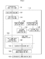
- FIG. 3 is a block diagram illustrating an example of the main part of the image processing apparatus
- FIG. 4 is a flowchart illustrating a procedure of a first embodiment of image processing
- FIG. 5 is an explanatory diagram illustrating an exemplary photographing scene
- FIG. 6 is an explanatory diagram for illustrating basic information of a face frame
- FIG. 7 is an explanatory diagram for illustrating calculation of a face parallax amount
- FIG. 8 is a flowchart illustrating a procedure of a second embodiment of image processing
- FIG. 9A is a diagram illustrating an exemplary display image when the face frame are not blurred
- FIG. 9B is a diagram illustrating an exemplary display image when the face frame are blurred
- FIG. 10 is a block diagram illustrating the whole configuration of a 3D digital camera to which the presently disclosed subject matter is applied.
- FIG. 1 is a block diagram illustrating the whole configuration of an exemplary image processing apparatus according to the presently disclosed subject matter.
- an image processing apparatus 100 includes a stereoscopic image input unit 101 , a signal processing unit 102 , a stereoscopic image display unit 103 , an image recording unit 104 , an operating unit 105 , a storage unit 106 and a CPU (Central Processing Unit) 110 .
- a stereoscopic image input unit 101 a signal processing unit 102 , a stereoscopic image display unit 103 , an image recording unit 104 , an operating unit 105 , a storage unit 106 and a CPU (Central Processing Unit) 110 .
- CPU Central Processing Unit
- the stereoscopic image input unit 101 is an input device used to input a stereoscopic image (otherwise referred to as a “stereoscopic photographed image”).
- the stereoscopic image is composed of a plurality of photographed images (a plurality of planar images) obtained respectively by photographing a subject from a plurality of viewpoints.
- the stereoscopic image is not particularly limited to a real viewpoint image obtained by practically photographing a subject from a plurality of viewpoints, but may be a virtual viewpoint image obtained by virtually photographing a subject from a plurality of virtual viewpoints, that is, an image obtained by applying an image processing to the real viewpoint image.
- the stereoscopic image is not particularly limited to a stereoscopic image composed of a plurality of planar images, but may be a stereoscopic image composed by adding depth information to a planar image of one viewpoint generated from a plurality of planar images.
- the depth information indicates, for example, a parallax amount between each point (each pixel) in the image, or information corresponding to the parallax amount.
- the input device constituting the stereoscopic image input unit 101 is not particularly limited to a case where a stereoscopic image is directly inputted by use of a plurality of image pickup devices each including a photographic lens and an image pickup element, but may be a recording medium interface which reads a stereoscopic image from a recording medium such as a memory card, or may be a network interface which receives a stereoscopic image via a network.
- the signal processing unit 102 applies various types of signal processings to a stereoscopic image.
- the stereoscopic image display unit 103 is a display device which displays a stereoscopic image in a manner allowing stereoscopic vision.
- a 3D (three dimensional) liquid crystal display device using light direction control system is used, for example.
- the direction of backlight illuminating the rear surface of the liquid crystal display device is regulated to a right-eye direction and left-eye direction of the observer. Accordingly, a left photographed image is provided to the left eye of the observer, and a right photographed image is provided to the right eye.
- a stereoscopic vision display device using a parallax barrier system may also be used. In the parallax barrier system, an image is given to the observer through slits vertically carved.
- a stereoscopic vision display device provided with a lenticular lens including a group of hog-backed lenses may be used.
- stereoscopic vision may be given by making the observer wear image separation glasses.
- the display device is not particularly limited to the liquid crystal display devices; an organic EL display device (organic light emitting display device) may be used.
- the image recording unit 104 is a device by which a stereoscopic image is recorded on a recording medium such as a memory card.
- the operating unit 105 is an input device through which the user inputs a command.
- the operating unit 105 is constituted of key switches, for example.
- the operating unit 105 may include a pointing device or a touch panel sensor.
- the storage unit 106 including a nonvolatile memory, stores various types of information.
- the CPU (Central Processing Unit) 110 controls according to programs the units of the image processing apparatus 100 .
- subject distance is used to indicate not only a distance to an in-focus object (primary subject) but also a distance to an out-of-focus object (secondary subject).
- the radius x of circle of confusion of the photographic lens is calculated using formula 1.
- the aperture value of the photographic lens is F
- the radius x of circle of confusion (rear blurring amount) at a light spot displaced by d from the focal point is expressed by formula 2.
- x df 2 /2 ⁇ F ( a ⁇ f )( a+d ) ⁇ [Formula 2]
- the blurring amount increases in proportion to the second power of focal distance f, and is inversely proportional to aperture value F, and decreases substantially in proportion to the second power of in-focus surface distance.
- the difference of distance from the in-focus surface is proportional to d/(a+d) in a case of rear focus, and is proportional to d/(a ⁇ d) in a case of front focus.
- focal distance f and aperture value F the blurring amount of each face image can be calculated based on a difference between distance (primary subject distance) to an in-focus face and distance (secondary subject distance) to an out-of-focus face.
- each of a left image pickup device 11 L and a right image pickup device 11 R includes a photographic lens having a zoom lens, focus lens and aperture, and an image pickup element such as a CCD sensor.
- an image pickup element such as a CCD sensor.
- the focal distance of the photographic lens of the image pickup devices 11 L and 11 R, the convergence angle ⁇ c (angle between the optical axes (photographing directions) of the image pickup devices 11 L and 11 R), and the baseline length SB (distance (relative distance between the image pickup devices) between the optical axes of the image pickup devices 11 L and 11 R)) are fixed.
- planar images 92 L and 92 R contain subject images 93 L and 93 R projected by the same subject 91 , respectively.
- a stereoscopic image 94 is reproduced.
- An observer 95 views the stereoscopic image 94 on the monitor with both eyes 96 L and 96 R. As a result, it seems to the observer 95 that a virtual image 97 of the subject 91 “moves to the front side.” Referring to Portion 1 of FIG. 2 , the subject 91 is positioned closer than a cross point 99 of the optical axes; thus, the virtual image 97 appears to move to the front side. However, when the subject is positioned more distant than the cross point 99 , the virtual image 97 appears to move to the rear side.
- the parallax amount AP difference of position between the pixel 98 L and pixel 98 R
- a “forward movement” amount AD of the virtual image 97 of the observer 95 becomes also larger.
- the parallax amount AP becomes larger, and a “backward movement” amount of the virtual image of the observer 95 becomes also larger.
- the subject distance S can be associated with the parallax amount AP over a range around the cross point 99 .
- the subject distance S can be associated uniquely with the parallax amount AP.
- the subject distance S may be calculated based also on the variable parameter.
- Focusing state identification by a focusing state identifying unit 114 of FIG. 1 will be described.
- a defocus amount of face position is determined using a difference (parallax amount) between a face position (face coordinate) in the left photographed image and a face position (face coordinate) in the right photographed image.
- face images are detected in the left photographed image and the right photographed image.
- the position of the detected face image in the photographed images is identified for each of the detected face images.
- the parallax amount of the face images is detected for each face image.
- distance information for example, distance between the photographic lens and the face
- distance information on the face position is identified at least based on the parallax amount of the face image, the relative distance between the plurality of image pickup devices, and the photographing directions of the image pickup devices.
- the blurring amount (defocus amount) of an out-of-focus face image is identified based on distance information on the position (in-focus position) of an in-focus object (for example, face), on distance information on the position of the out-of-focus face, and on the focal distance and the aperture value.
- the presently disclosed subject matter can also be applied to a case in which distance information on face position is determined without using a parallax amount.
- distance information on face position is directly acquired.
- a distance image is also acquired using a distance image sensor.
- the blurring amount of an out-of-focus face image is identified based on distance information on an in-focus position, distance information on the position of the out-of-focus face, and the focal distance and the aperture value.
- the defocus amount of a face image is directly identified.
- a pixel for phase difference detection is arranged along with an ordinary pixel for photography, and the defocus amount of a face image is determined based on an output signal of the pixel for phase difference detection.
- the third and fourth aspects require extra hardware; on the other hand, the first and second aspects are advantageous in that extra hardware is not needed. Further, the first aspect is also advantageous in that information on the position of a face frame acquired by the ordinary face detecting processing can be used as information on face position, and thus the blurring amount of the face can be readily and quickly acquired.
- FIG. 3 is a block diagram illustrating an example of the main part of the image processing apparatus 100 illustrated in FIG. 1 .
- a CPU 110 includes a face detecting unit 122 , a face position identifying unit 124 , a parallax amount detecting unit 142 , a distance information acquiring unit 144 , an in-focus position identifying unit 146 , a focusing state identifying unit 148 , a face frame generating unit 160 and a stereoscopic display image generating unit 180 .
- the face detecting unit 122 detects a face image (the abbreviation “face” being also used below) in each photographed image constituting the stereoscopic image.
- face image detection may be performed by a well-known technique, and an explanation thereof is omitted here.
- the face position identifying unit 124 identifies the position of the face image detected by the face detecting unit 122 in each photographed image constituting the stereoscopic image. For example, the coordinates, height and width of the face image are identified.
- the parallax amount detecting unit 142 detects a difference of the positions (parallax amount) of the face image detected by the face detecting unit 122 between respective photographed images constituting the stereoscopic image. In the case of two viewpoints, a difference of face image positions between the left photographed image and right photographed image is calculated.
- the distance information acquiring unit 144 calculates a distance (distance information on face position) from the cross point ( 99 in Portion 1 of FIG. 2 ) to the face based on the parallax amount (AP in Portion 2 of FIG. 2 ) of a face image, the relative distance (baseline length) between the plurality of image pickup devices ( 11 L and 11 R in Portion 1 of FIG. 2 ), and the pickup direction (optical axis direction) of the image pickup devices.
- the focal distance of the plurality of image pickup devices is variable, the subject distance is calculated based also on the focal distance.
- the in-focus position identifying unit 146 identifies in-focus positions in respective photographed images constituting the stereoscopic image. For example, it is identified which face is in focus, or which object except face is in focus.
- the focusing state identifying unit 148 identifies the focusing state of face position for each face detected by the face detecting unit 122 , based on the in-focus position identified by the in-focus position identifying unit 146 and the distance information on face position acquired by the distance information acquiring unit 144 .
- the focusing state of face position is identified based also on distance information on the position (in-focus position) of the object. For example, the radius of circle of confusion is calculated as a defocus amount of the face image.
- the focal distance and the aperture value are variable, the radius of circle of confusion is calculated based also on these variable parameters.
- the face frame generating unit 160 generates, for each detected face, a face frame indicating the position of the face and blurred according to the focusing state of the position of the face. For example, a face frame is produced in a stereoscopic state, and blurred in a stereoscopic state by use of a three-dimensional filter.
- the face frame generating unit 160 of this example includes a face frame basic information generating unit 162 and a blurring processing unit 164 .
- the face frame basic information generating unit 162 generates, for each face image, the position and size of a face frame, and face frame basic information indicating the color and shape of the face frame.
- the color and shape of the face frame may be different for each face image.
- the blurring processing unit 164 identifies, for each face image, a blurring amount (filter coefficient) of a face frame according to the defocus amount of the face image, and applies a filtering processing to the face frame.
- the stereoscopic display image generating unit 180 generates an image (otherwise referred to as a “stereoscopic display image”) capable of being stereoscopically displayed on the stereoscopic image display unit 103 , based on the face frame generated by the face frame generating unit 160 and the stereoscopic image inputted to the stereoscopic image input unit 101 .
- FIG. 4 is a flowchart illustrating a procedure of a first embodiment of image processing.
- a stereoscopic image is inputted through the stereoscopic image input unit 101 .
- the stereoscopic image of this example is a photographed image of two viewpoints composed of a left photographed image and a right photographed image. Descriptions will be given below assuming that the stereoscopic image contains a plurality of face images (otherwise referred to simply as a “face”) which are different in subject distance.
- step S 4 face detection and face position identification in the stereoscopic image are performed.
- the face detecting unit 122 detects a plurality of face images in each of the left photographed image and the right photographed image.
- the face position identifying unit 124 identifies, for each detected face image, the position and size of a face image in each photographed image. For example, as illustrated in FIG. 5 , when three persons are photographed by the left image pickup device 11 L and the right image pickup device 11 R, face images of the three persons are detected, and the coordinates and size of each face image are identified.
- the number of detected face images are set as variables i and k.
- step S 6 the face frame generating unit 160 generates face frame basic information for each face image. For example, face frame basic information on face frames 81 L, 82 L and 83 L for the left photographed image illustrated in FIG. 6 and face frame basic information on face frames 81 R, 82 R and 83 R for the right photographed image are generated.
- face frames of the three persons are different in position and size, but are non-blurred frames.
- the face frames illustrated in FIG. 6 are not practically displayed, but only the basis information for displaying the face frame is generated.
- step S 8 the focusing state of a face image is identified for each face image. More specifically, a defocus amount is calculated in the following way.
- the parallax amount detecting unit 142 detects, for each face image, as a parallax amount, a difference between the face image position in the left photographed image and the face image position in the right photographed image.
- differences AP 1 , AP 2 and AP 3 between the position of the face frames 81 L, 82 L and 83 L in the left photographed image and the position of the face frames 81 R, 82 R and 83 R in the right photographed image are, as illustrated in FIG. 7 , calculated as the parallax amount.
- the parallax amount is composed of: a sign indicating whether the face is closer than the cross point ( 99 of FIG. 2 ) of optical axes of the image pickup devices ( 11 L and 11 R of FIG. 2 ); and an absolute value corresponding to a distance from the cross point 99 to the face.
- the distance information acquiring unit 144 calculates, for each face image, distance information on face position based on the parallax amount, the convergence angle ( ⁇ c of FIG. 2 ) and the baseline length (SB of FIG. 2 ).
- the focal distance is fixed, but when the focal distance is variable, the subject distance is calculated based also on the variable focal distance.
- a distance relative to the cross point 99 is calculated as the distance information on face position, but a distance from the photographic lens to the face may be calculated.
- the in-focus position identifying unit 146 identifies an in-focus position in each photographed image. In this example, it is identified which face is in focus. For example, a largest face in the image, a face closet to the image pickup device, or a face specified by the user is in focus.
- the focusing state identifying unit 148 identifies for each face image, a defocus amount of the face image. For example, the radius of circle of confusion is calculated based on the in-focus position, the distance information on face position, the focal distance f and the aperture value F.
- the defocus amount of an out-of-focus face image is identified based also on the distance information on the in-focus position.
- step S 10 it is determined whether an i-th face is in focus. If it is determined that the i-th face is in focus, the operation proceeds to step S 14 ; if it is determined that the i-th face is out of focus, the operation proceeds to step S 12 .
- step S 12 the face frame generating unit 160 performs a filtering processing of blurring the i-th face frame. For example, Gaussian filter is applied so that a point image (point pixel) in the inner side of each face frame is blurred.
- the focusing state identifying unit 114 determines whether the radius of circle of confusion is in an allowable range. If the radius of circle of confusion is in the allowable range, it is identified that the face position is in an in-focus state; if the radius of circle of confusion is not in the allowable range, it is identified that the face position is in an out-of-focus state.
- the face frame generating unit 160 does not apply a filtering processing to the face frame when the face position is in the in-focus state, or applies a filtering processing to the face frame when the face position is in the out-of-focus state. That is, when the face position is in the out-of-focus state, the face frame generating unit 160 changes the face frame to a more blurred state than when the face position is in the in-focus state.
- step S 14 i is decremented, and in step S 16 , it is determined whether i is equal to zero. If i is equal to zero, i.e., when in-focus determination of all the faces has been done, the operation proceeds to step S 18 ; if i is not equal to zero, the operation returns to step S 10 .
- step S 18 the stereoscopic display image generating unit 180 generates a display image based on the inputted stereoscopic image and the generated face frames.
- each of the photographed images constituting the stereoscopic image is combined with the face frames.
- a blurred face frame is preliminarily stored in the storage unit 106 , and when the defocus amount of face position is not in an allowable range, the ordinary face frame is switched to the blurred face frame.
- the focusing state of a face may be determined based on a tag (additional information) of an image file containing a stereoscopic image.
- FIG. 8 is a flowchart illustrating a procedure of a second embodiment of image processing.
- Steps S 22 to S 28 are similar to steps S 2 to S 8 of the first embodiment illustrated in FIG. 4 , thus, the explanation as to steps S 22 to S 28 is omitted.
- step S 30 it is determined whether an i-th face is in-focus. If it is determined that an i-th face is in focus, the operation proceeds to step S 34 ; if it is determined that an i-th face is not in focus, the operation proceeds to step S 32 .
- step S 32 the face frame generating unit 160 performs a filtering processing of blurring the i-th face according to a defocus amount.
- filter coefficient is changed according to the defocus amount of each face image.
- the filter coefficient having multiple levels for example, five levels
- the level of the filter coefficient is selected so that as the defocus amount of a face image increases, the blurring amount of the face frame becomes larger.
- the selection is made according to the radius of circle of confusion. That is, the blurring amount of a face frame is changed according to the defocus amount of the face image.
- step S 34 i is decremented, and in step S 36 , it is determined whether i is equal to zero. If i is equal to zero, the operation proceeds to step S 38 ; if i is not equal to zero, the operation returns to step S 30 .
- Step S 38 is similar to step S 18 of the first embodiment.
- FIG. 9A is a diagram illustrating an exemplary display image when the face frame is not blurred
- FIG. 9B is a diagram illustrating an exemplary display image when the face frame is blurred
- FIGS. 9A and B illustrate display images including three faces to which face frames are attached. Among the three faces, only one face is in-focus, and the other two are out of focus.
- FIG. 9A while two faces are displayed in a blurred manner, the face frames around the faces are clearly displayed. Consequently, the observer is more likely to perceive that a face at the in-focus position and a more distant face are at the same distance. That is, the face frames disturb stereoscopic effect.
- FIG. 9B While the face frame of a face at the in-focus position looks clear, the face frames of more distant faces look blurred. That is, the displaying states of face frames correspond to the focusing states of faces. Thus, the face frames do not disturb stereoscopic effect.
- FIGS. 9A and 9B an image from one viewpoint is illustrated for the convenience of explanation. However, images (stereoscopic display image) from multiple viewpoints are practically displayed in the stereoscopic image display unit 103 .
- FIG. 10 is a block diagram illustrating the whole configuration of a 3D digital camera to which the presently disclosed subject matter is applied.
- a 3D digital camera 1 is a stereoscopic imaging apparatus which can photograph the same subject from a plurality of viewpoints to generate a stereoscopic image, and includes a CPU 10 , an image pickup system 11 ( 11 R, 11 L), an operating unit 12 , a ROM (Read Only Memory) 16 , a flash ROM 18 , an SDRAM (Synchronous Random Access Memory) 20 , a VRAM (Video RAM) 22 , a zoom lens control unit 24 ( 24 L, 24 R), a focus lens control unit 26 ( 26 L, 26 R), an aperture control unit 28 ( 28 L, 28 R), an image pickup element control unit 36 ( 36 L, 36 R), an analog signal processing unit 38 ( 38 L, 38 R), an A/D (Analog-Digital) converter 40 ( 40 L, 40 R), an image input controller 41 ( 41 L, 41 R), a digital signal processing unit 42 ( 42 L, 42 R), an AF evaluation value acquiring unit 44 , an AE/AWB (Auto-
- the left-eye image pickup system 11 L (otherwise referred to as a “left image pickup device”) mainly includes a photographic lens 14 L, a zoom lens control unit 24 L, a focus lens control unit 26 L, an aperture control unit 28 L, an image pickup element 34 L, an image pickup element control unit 36 L, an analog signal processing unit 38 L, an A/D converter 40 L, an image input controller 41 L and a digital signal processing unit 42 L.
- the right-eye image pickup system 11 R (otherwise referred to as a “right image pickup device”) mainly includes a photographic lens 14 R, a zoom lens control unit 24 R, a focus lens control unit 26 R, an aperture control unit 28 R, an image pickup element 34 R, an image pickup element control unit 36 R, an analog signal processing unit 38 R, an A/D converter 40 R, an image input controller 41 R and a digital signal processing unit 42 R.
- an image signal obtained by photographing a subject with the image pickup system ( 11 L, 11 R) is referred to as a “photographed image.”
- a photographed image captured by the left-eye image pickup system 11 L is referred to as a “left photographed image.”
- a photographed image captured by the right-eye image pickup system 11 R is referred to as a “right photographed image.”
- the CPU 10 functions as a control device which performs overall control of the operations in the whole digital camera, such as imaging and reproduction, and controls based on an input from the operating unit 12 , each of the units according to programs.
- the operating unit 12 includes a shutter button, a power supply switch, a mode switch, a zoom button, an arrow button, a menu button, an OK button and a BACK button.
- the shutter button is constituted of a two-stroke switch which allows “halfway depression” and “full depression.”
- the power supply switch is a switch for selecting ON or OFF of the power supply of the digital camera 1 .
- the mode switch is a switch for selecting one from among different modes.
- the zoom button is used for a zooming operation.
- the arrow button can be manipulated in four directions (up, down, left and right), and is used for different setting operations along with the menu button, the OK button and the BACK button.
- Programs executed by the CPU 10 and various types of data and the like needed for the control by the CPU 10 are stored in the ROM 16 connected via a bus 14 .
- Various types of setting information and the like on the operation of the digital camera 1 such as user setting information is stored in the flash ROM 18 .
- the SDRAM 20 is used as an arithmetic operation area of the CPU 10 , and also used as a temporary storage area for image data.
- the VRAM 22 is used as a temporary storage area dedicated to displayed image data.
- a pair (left, right) of the photographic lenses 14 L and 14 R includes zoom lenses 30 ZL and 30 ZR, focus lenses 30 FL and 30 FR, and apertures 32 L and 32 R.
- the zoom lenses 30 ZR and 30 LR are driven by the zoom lens control units 24 R and 24 L acting as a zoom lens drive device, and move longitudinally along the optical axis.
- the CPU 10 controls the position of the zoom lenses 30 LR and 30 ZR through the zoom lens control units 24 L and 24 R, so that a zooming operation of the photographic lenses 14 L and 14 R is performed.
- the focus lenses 30 FL and 30 FR are driven by the focus lens control units 26 L and 26 R acting as a focus lens drive device, and move longitudinally along the optical axis.
- the CPU 10 controls the position of the focus lenses 30 FL and 30 FR through the focus lens control units 26 L and 26 R, so that a focusing operation of the photographic lenses 14 L and 14 R is performed.
- the apertures 32 L and 32 R are constituted of an iris aperture, for example, and driven by the aperture control units 28 L and 28 R acting as an aperture drive device, so that an opening amount (aperture value) is varied.
- the CPU 10 controls the opening amount of the aperture through the aperture control units 28 L and 28 R so that the exposure amount of the image pickup elements 34 L and 34 R is regulated.
- the image pickup elements 34 L and 34 R are constituted of a color CCD (Charge Coupled Device) image pickup element having predetermined color filter arrangement.
- the CCD has a light receiving surface on which many photodiodes are two-dimensionally arranged.
- An optical image (subject image) of a subject focused through the photographic lens ( 14 L and 14 R) on the light receiving surface of the CCD is converted to signal electric charges according to the amount of incident light by the photodiodes.
- the signal electric charges accumulated on each photodiode are sequentially read out from the image pickup elements 34 L and 34 R as a voltage signal (image signal) dependent on the signal electric charges, based on a drive pulse supplied from the image pickup element control units 36 L and 36 R in response to a command from the CPU 10 .
- the image pickup elements 34 L and 34 R are provided with a function of electrical shutter; thus, the exposure time (shutter speed) is regulated by changing the electric charge accumulation time of the photodiodes.
- CCDs are used as the image pickup element; but an image pickup element of another structure such as a CMOS (Complementary Metal-Oxide Semiconductor) sensor may be used.
- CMOS Complementary Metal-Oxide Semiconductor
- the CPU 10 drives the left and right photographic lenses 14 L and 14 R in a synchronized manner. More specifically, the left and right photographic lenses 14 L and 14 R are set to the same focal distance (zoom ratio) at all times; and the position of the focus lenses 30 FL and 30 FR is set so that the same subject is in focus at all times. Further, the aperture value and the exposure time (shutter speed) are regulated so that the same amount of exposure is provided at all times.
- the analog signal processing units 38 L and 38 R include a correlation double sampling circuit (CD) for removing reset noises (low frequency) contained in an image signal outputted from the image pickup elements 34 L and 34 R, and an AGC (Automatic Gain Control) circuit for amplifying the image signal to regulate the image signal to a given level.
- the analog signal processing units 38 R and 38 L apply a correlation double sampling processing to the image signal outputted from the image pickup elements 34 L and 34 R, and amplify the image signal.
- the A/D converters 40 L and 40 R convert the analog image signal outputted from the analog signal processing units 38 L and 38 R into a digital image signal.
- the image input controllers 41 L and 41 R receive the image signal outputted from the A/D converters 40 L and 40 R and store the image signal in the SDRAM 20 .
- the left photographed image and right photographed image are temporarily stored in the SDRAM 20 .
- the digital signal processing units 42 L and 42 R receive according to a command from the CPU 10 , the image signal stored in the SDRAM 20 , and apply a predetermined signal processing to the image signal to generate image data (Y/C signal) composed of a luminance signal Y and color-difference signals Cr and Cb.
- the digital signal processing units 42 L and 42 R also apply according to a command from the CPU 10 , various types of digital corrections such as offset processing, white balance adjustment processing, gamma correction processing, RGB interpolation processing, RGB/YC conversion processing, noise reduction processing, contour correction processing, color tone correction and light source type determination processing.
- the digital signal processing units 42 L and 42 R may be constituted of a hardware circuit, or the same function may be constituted of software.
- the AF evaluation value acquiring unit 44 calculates an AF evaluation value (in-focus evaluation value) for detecting an in-focus position of the focus lens 30 F based on the image signals (photographed images) of R, G and B written into the SDRAM 20 by one of the image input controllers 41 .
- the AF evaluation value acquiring unit 44 of this example also includes a high-pass filter allowing passage of only high frequency components of the G signal, a signal extracting unit which cuts out a signal from each detection block, and an integration unit which integrates the absolute value of signal in each detection block, and outputs the integration value of each detection block as an AF evaluation value.
- the AF evaluation value of this example indicates an in-focus degree in each detection block.
- the CPU 10 detects a lens position at which the AF evaluation value outputted from the AF evaluation value acquiring unit 44 has a maximum value, in the focusing area composed of the plurality of blocks. Then, the CPU 10 moves the focus lenses 30 FL and 30 FR to that position, so that the focusing of the focus lenses 30 FL and 30 FR is performed.
- the CPU 10 firstly moves the focus lenses 30 FL and 30 FR from close range to infinity, and sequentially acquires an AF evaluation value from the AF evaluation value acquiring unit 44 during the movement of the focus lenses 30 FL and 30 FR, and detects a lens position at which the AF evaluation value has a maximum value, in the in-focus position detection area, and moves the focus lenses 30 FL and 30 FR to that lens position.
- a subject which lies in the focus area within the field angle is in focus.
- the AE/AWB evaluation value acquiring unit 46 calculates evaluation values needed for AE (automatic exposure) and AWB (automatic white balance adjustment) based on the image signals (photographed images) of R, G and B written into the SDRAM 20 by one of the image input controllers 41 .
- the CPU 10 calculates an exposure amount based on the AE evaluation value. That is, the CPU 10 determines sensitivity, aperture value, shutter speed, necessity of flash exposure and the like.
- the CPU 10 acquires an AWB evaluation value and calculates a gain value for white balance adjustment, and in addition, detects the type of light source.
- the compression/expansion processing unit 52 applies, according to a command from the CPU 10 , a compression processing of a predetermined format to inputted image data to generate compressed image data.
- the compression/expansion processing unit 52 also applies, according to a command from the CPU 10 , an expansion processing of a predetermined format to inputted compressed image data to generate non-compressed image data.
- the media control unit 54 controls according to a command from the CPU 10 , reading/writing of data from/into the memory card 56 .
- the monitor control unit 58 controls according to a command from the CPU 10 , displaying on the monitor 60 .
- the monitor 60 is used as an image display unit for displaying a captured image and also used as GUI during various types of settings.
- the monitor 60 sequentially displays images (through-images) continuously captured by the image pickup elements 34 R and 34 L, that is, the monitor 60 is used as an electrical finder.
- the power supply control unit 61 controls according to a command from the CPU 10 , supplying of power from the battery 62 to the above units.
- the flash control unit 64 controls light emitting of the flash 65 according to a command from the CPU 10 .
- the posture detecting sensor 66 detects the posture (up/down, left/right tilt) of the body of the digital camera 1 , and outputs the result to the CPU 10 .
- the posture detecting sensor 66 detects a tilt angle (rotational angle around the optical axis of the photographic lenses 14 L and 14 R) in a horizontal direction of the body of the digital camera 1 and a tilt angle (tilt angle in a vertical direction of the optical axis of the photographic lenses 14 L and 14 R) in a vertical direction of the body of the digital camera 1 .
- the loudspeaker 67 outputs sound.
- the clock unit 68 counts the current time and data, and in addition, performs time measurement according to a command from the CPU 10 .
- the left image pickup system 11 L and the right image pickup system 11 R of FIG. 10 constitute the stereoscopic image input unit 101 of FIG. 1
- the digital signal processing units 42 L and 42 R, and the like of FIG. 10 constitute the signal processing unit 102 of FIG. 1
- the monitor 60 of FIG. 10 constitutes the stereoscopic image display unit 103 of FIG. 1
- the media control unit 54 of FIG. 10 constitutes the image recording unit 104 of FIG. 1
- the operating unit 12 of FIG. 10 constitutes the operating unit 105 of FIG. 1
- the ROM 16 , the flash ROM 18 , the SDRAM 20 and the like of FIG. 10 constitute the storage unit 106 of FIG. 1
- the CPU 10 of FIG. 10 constitutes the CPU 110 of FIG. 1 .
- the image processing apparatus may be used in a 3D digital camera.
- the presently disclosed subject matter may be applied to various types of image processing apparatuses which generate a stereoscopic display image containing a face frame.
- the presently disclosed subject matter may be applied to a computer apparatus which applies an editing processing to a stereoscopic image captured by a 3D digital camera.
Abstract
Description
1/a+1/b=f [Formula 1]
x=df 2/2{F(a−f)(a+d)} [Formula 2]
x=df 2/2{F(a−f)(a−d)} [Formula 3]
Claims (11)
Applications Claiming Priority (2)
| Application Number | Priority Date | Filing Date | Title |
|---|---|---|---|
| JP2009-228226 | 2009-09-30 | ||
| JP2009228226A JP5346266B2 (en) | 2009-09-30 | 2009-09-30 | Image processing apparatus, camera, and image processing method |
Publications (2)
| Publication Number | Publication Date |
|---|---|
| US20110074928A1 US20110074928A1 (en) | 2011-03-31 |
| US8599245B2 true US8599245B2 (en) | 2013-12-03 |
Family
ID=43779906
Family Applications (1)
| Application Number | Title | Priority Date | Filing Date |
|---|---|---|---|
| US12/893,799 Expired - Fee Related US8599245B2 (en) | 2009-09-30 | 2010-09-29 | Image processing apparatus, camera, and image processing method |
Country Status (2)
| Country | Link |
|---|---|
| US (1) | US8599245B2 (en) |
| JP (1) | JP5346266B2 (en) |
Cited By (2)
| Publication number | Priority date | Publication date | Assignee | Title |
|---|---|---|---|---|
| US20130215105A1 (en) * | 2012-02-17 | 2013-08-22 | Nintendo Co., Ltd. | Storage medium having stored therein display control program, display control apparatus, display control system, and display control method |
| US20140078173A1 (en) * | 2007-03-30 | 2014-03-20 | Casio Computer Co., Ltd. | Image pickup apparatus equipped with face-recognition function |
Families Citing this family (23)
| Publication number | Priority date | Publication date | Assignee | Title |
|---|---|---|---|---|
| JP4787369B1 (en) * | 2010-03-30 | 2011-10-05 | 富士フイルム株式会社 | Image processing apparatus and method, and program |
| US8768044B2 (en) | 2010-09-14 | 2014-07-01 | Texas Instruments Incorporated | Automatic convergence of stereoscopic images based on disparity maps |
| TWI441093B (en) * | 2010-10-29 | 2014-06-11 | Altek Corp | Method for generating three dimensional image and three dimensional imaging system |
| JP5627438B2 (en) * | 2010-12-14 | 2014-11-19 | キヤノン株式会社 | IMAGING DEVICE, ITS CONTROL METHOD, PROGRAM, AND STORAGE MEDIUM |
| JP5811602B2 (en) * | 2010-12-16 | 2015-11-11 | ソニー株式会社 | Image generation apparatus, program, image display system, and image display apparatus |
| JP5874192B2 (en) | 2011-04-11 | 2016-03-02 | ソニー株式会社 | Image processing apparatus, image processing method, and program |
| JP5917017B2 (en) * | 2011-05-11 | 2016-05-11 | キヤノン株式会社 | Image processing apparatus, control method therefor, and program |
| JP2014170981A (en) * | 2011-06-29 | 2014-09-18 | Panasonic Corp | Image pickup device |
| JP5848536B2 (en) * | 2011-07-05 | 2016-01-27 | キヤノン株式会社 | IMAGING DEVICE, IMAGE GENERATION DEVICE, CONTROL METHOD THEREOF, PROGRAM, AND RECORDING MEDIUM |
| WO2013046833A1 (en) | 2011-09-30 | 2013-04-04 | 富士フイルム株式会社 | Image display device, disparity adjustment display method therefor, and image capturing device |
| JP5840022B2 (en) * | 2012-02-17 | 2016-01-06 | キヤノン株式会社 | Stereo image processing device, stereo image imaging device, stereo image display device |
| JP5884579B2 (en) * | 2012-03-19 | 2016-03-15 | 株式会社リコー | Imaging apparatus and display processing method |
| US20140015854A1 (en) * | 2012-07-13 | 2014-01-16 | Research In Motion Limited | Application of Filters Requiring Face Detection in Picture Editor |
| US9508119B2 (en) * | 2012-07-13 | 2016-11-29 | Blackberry Limited | Application of filters requiring face detection in picture editor |
| EP2912602A4 (en) * | 2012-10-23 | 2016-03-16 | Ishay Sivan | Real time assessment of picture quality |
| JP6218377B2 (en) * | 2012-12-27 | 2017-10-25 | キヤノン株式会社 | Image processing apparatus and image processing method |
| US9161020B2 (en) * | 2013-04-26 | 2015-10-13 | B12-Vision Co., Ltd. | 3D video shooting control system, 3D video shooting control method and program |
| JP2015012304A (en) * | 2013-06-26 | 2015-01-19 | ソニー株式会社 | Image processing apparatus, image processing method, and program |
| JP6381273B2 (en) | 2014-05-02 | 2018-08-29 | キヤノン株式会社 | Imaging apparatus, image processing system, and control method thereof |
| US10498976B2 (en) * | 2014-12-05 | 2019-12-03 | Microsoft Technology Licensing, Llc | Virtual focus feedback |
| JP6752681B2 (en) | 2016-10-19 | 2020-09-09 | キヤノン株式会社 | Display control device, control method and program of display control device, and storage medium |
| JP6778602B2 (en) * | 2016-12-14 | 2020-11-04 | 三星電子株式会社Samsung Electronics Co.,Ltd. | Image pickup device, image data generation method and image data generation program |
| US10499001B2 (en) * | 2017-03-16 | 2019-12-03 | Gvbb Holdings S.A.R.L. | System and method for augmented video production workflow |
Citations (6)
| Publication number | Priority date | Publication date | Assignee | Title |
|---|---|---|---|---|
| US6549650B1 (en) * | 1996-09-11 | 2003-04-15 | Canon Kabushiki Kaisha | Processing of image obtained by multi-eye camera |
| US7079669B2 (en) * | 2000-12-27 | 2006-07-18 | Mitsubishi Denki Kabushiki Kaisha | Image processing device and elevator mounting it thereon |
| US20070242861A1 (en) | 2006-03-30 | 2007-10-18 | Fujifilm Corporation | Image display apparatus, image-taking apparatus and image display method |
| US20080118156A1 (en) | 2006-11-21 | 2008-05-22 | Sony Corporation | Imaging apparatus, image processing apparatus, image processing method and computer program |
| JP2008252713A (en) | 2007-03-30 | 2008-10-16 | Nikon Corp | Imaging device |
| US8068164B2 (en) * | 2007-09-14 | 2011-11-29 | Sony Corporation | Face recognition auto focus apparatus for a moving image |
Family Cites Families (2)
| Publication number | Priority date | Publication date | Assignee | Title |
|---|---|---|---|---|
| JP4427515B2 (en) * | 2006-01-27 | 2010-03-10 | 富士フイルム株式会社 | Target image detection display control apparatus and control method thereof |
| JP2009053748A (en) * | 2007-08-23 | 2009-03-12 | Nikon Corp | Image processing apparatus, image processing program, and camera |
-
2009
- 2009-09-30 JP JP2009228226A patent/JP5346266B2/en not_active Expired - Fee Related
-
2010
- 2010-09-29 US US12/893,799 patent/US8599245B2/en not_active Expired - Fee Related
Patent Citations (8)
| Publication number | Priority date | Publication date | Assignee | Title |
|---|---|---|---|---|
| US6549650B1 (en) * | 1996-09-11 | 2003-04-15 | Canon Kabushiki Kaisha | Processing of image obtained by multi-eye camera |
| US7079669B2 (en) * | 2000-12-27 | 2006-07-18 | Mitsubishi Denki Kabushiki Kaisha | Image processing device and elevator mounting it thereon |
| US20070242861A1 (en) | 2006-03-30 | 2007-10-18 | Fujifilm Corporation | Image display apparatus, image-taking apparatus and image display method |
| JP2007274207A (en) | 2006-03-30 | 2007-10-18 | Fujifilm Corp | Image display device, image pickup device, and image display method |
| US20080118156A1 (en) | 2006-11-21 | 2008-05-22 | Sony Corporation | Imaging apparatus, image processing apparatus, image processing method and computer program |
| JP2008131405A (en) | 2006-11-21 | 2008-06-05 | Sony Corp | Imaging unit, image processing unit, image processing methods for the units, and program making computer execute the method |
| JP2008252713A (en) | 2007-03-30 | 2008-10-16 | Nikon Corp | Imaging device |
| US8068164B2 (en) * | 2007-09-14 | 2011-11-29 | Sony Corporation | Face recognition auto focus apparatus for a moving image |
Cited By (4)
| Publication number | Priority date | Publication date | Assignee | Title |
|---|---|---|---|---|
| US20140078173A1 (en) * | 2007-03-30 | 2014-03-20 | Casio Computer Co., Ltd. | Image pickup apparatus equipped with face-recognition function |
| US9042610B2 (en) * | 2007-03-30 | 2015-05-26 | Casio Computer Co., Ltd. | Image pickup apparatus equipped with face-recognition function |
| US20130215105A1 (en) * | 2012-02-17 | 2013-08-22 | Nintendo Co., Ltd. | Storage medium having stored therein display control program, display control apparatus, display control system, and display control method |
| US9019265B2 (en) * | 2012-02-17 | 2015-04-28 | Nintendo Co., Ltd. | Storage medium having stored therein display control program, display control apparatus, display control system, and display control method |
Also Published As
| Publication number | Publication date |
|---|---|
| JP2011077900A (en) | 2011-04-14 |
| JP5346266B2 (en) | 2013-11-20 |
| US20110074928A1 (en) | 2011-03-31 |
Similar Documents
| Publication | Publication Date | Title |
|---|---|---|
| US8599245B2 (en) | Image processing apparatus, camera, and image processing method | |
| US9560341B2 (en) | Stereoscopic image reproduction device and method, stereoscopic image capturing device, and stereoscopic display device | |
| JP5425554B2 (en) | Stereo imaging device and stereo imaging method | |
| EP2590421B1 (en) | Single-lens stereoscopic image capture device | |
| US8823778B2 (en) | Imaging device and imaging method | |
| JP2011039486A (en) | Imaging device, method, and program | |
| JP4815470B2 (en) | Image display device and image display method | |
| US9838667B2 (en) | Image pickup apparatus, image pickup method, and non-transitory computer-readable medium | |
| JP2011101240A (en) | Stereoscopic photographing device and photographing control method | |
| JP2011199478A (en) | Imaging device, display control method therefor, and 3d information obtaining system | |
| JP5449551B2 (en) | Image output apparatus, method and program | |
| US20110025824A1 (en) | Multiple eye photography method and apparatus, and program | |
| JP5160460B2 (en) | Stereo imaging device and stereo imaging method | |
| JP2012178688A (en) | Stereoscopic image photographing device | |
| JP2014036362A (en) | Imaging device, control method therefor, and control program | |
| CN103339948B (en) | 3D video playing device, 3D imaging device, and 3D video playing method | |
| US9124866B2 (en) | Image output device, method, and recording medium therefor | |
| JP5571257B2 (en) | Image processing apparatus, method, and program | |
| JP5366693B2 (en) | IMAGING DEVICE, IMAGING DEVICE CONTROL METHOD, AND COMPUTER PROGRAM | |
| JP2012015620A (en) | Solid imaging device | |
| JP2023157521A (en) | Electronic apparatus, method for controlling electronic apparatus, program, and storage medium | |
| JP2024008154A (en) | Image processing device, display device, and image processing method | |
| JP2012044319A (en) | Image processing device, image processing method and stereoscopic imaging device |
Legal Events
| Date | Code | Title | Description |
|---|---|---|---|
| AS | Assignment |
Owner name: FUJIFILM CORPORATION, JAPAN Free format text: ASSIGNMENT OF ASSIGNORS INTEREST;ASSIGNOR:MISAWA, TAKESHI;REEL/FRAME:025069/0160 Effective date: 20100924 |
|
| STCF | Information on status: patent grant |
Free format text: PATENTED CASE |
|
| FEPP | Fee payment procedure |
Free format text: PAYOR NUMBER ASSIGNED (ORIGINAL EVENT CODE: ASPN); ENTITY STATUS OF PATENT OWNER: LARGE ENTITY |
|
| FPAY | Fee payment |
Year of fee payment: 4 |
|
| FEPP | Fee payment procedure |
Free format text: MAINTENANCE FEE REMINDER MAILED (ORIGINAL EVENT CODE: REM.); ENTITY STATUS OF PATENT OWNER: LARGE ENTITY |
|
| LAPS | Lapse for failure to pay maintenance fees |
Free format text: PATENT EXPIRED FOR FAILURE TO PAY MAINTENANCE FEES (ORIGINAL EVENT CODE: EXP.); ENTITY STATUS OF PATENT OWNER: LARGE ENTITY |
|
| STCH | Information on status: patent discontinuation |
Free format text: PATENT EXPIRED DUE TO NONPAYMENT OF MAINTENANCE FEES UNDER 37 CFR 1.362 |
|
| FP | Lapsed due to failure to pay maintenance fee |
Effective date: 20211203 |