US7721829B2 - Traveling robot - Google Patents
Traveling robot Download PDFInfo
- Publication number
- US7721829B2 US7721829B2 US11/601,706 US60170606A US7721829B2 US 7721829 B2 US7721829 B2 US 7721829B2 US 60170606 A US60170606 A US 60170606A US 7721829 B2 US7721829 B2 US 7721829B2
- Authority
- US
- United States
- Prior art keywords
- wheel
- traveling
- frame
- driving wheel
- main body
- Prior art date
- Legal status (The legal status is an assumption and is not a legal conclusion. Google has not performed a legal analysis and makes no representation as to the accuracy of the status listed.)
- Expired - Fee Related, expires
Links
Images


Classifications
-
- B—PERFORMING OPERATIONS; TRANSPORTING
- B25—HAND TOOLS; PORTABLE POWER-DRIVEN TOOLS; MANIPULATORS
- B25J—MANIPULATORS; CHAMBERS PROVIDED WITH MANIPULATION DEVICES
- B25J5/00—Manipulators mounted on wheels or on carriages
- B25J5/007—Manipulators mounted on wheels or on carriages mounted on wheels
-
- B—PERFORMING OPERATIONS; TRANSPORTING
- B62—LAND VEHICLES FOR TRAVELLING OTHERWISE THAN ON RAILS
- B62D—MOTOR VEHICLES; TRAILERS
- B62D61/00—Motor vehicles or trailers, characterised by the arrangement or number of wheels, not otherwise provided for, e.g. four wheels in diamond pattern
- B62D61/12—Motor vehicles or trailers, characterised by the arrangement or number of wheels, not otherwise provided for, e.g. four wheels in diamond pattern with variable number of ground engaging wheels, e.g. with some wheels arranged higher than others, or with retractable wheels
Definitions
- the present general inventive concept relates to a traveling robot, and more particularly, to a traveling robot having an enhanced traveling ability to travel along an uneven surface.
- a robot performs dangerous, simple, repetitional, precise, large scale or great amount of works for a human.
- the robot is widely used in industrial, military, domestic or other fields.
- a traveling apparatus is essential to the robot which should move to perform a work.
- technologies have been being developed for the traveling apparatus of the robot, and especially, for the traveling apparatus allowing the robot to smoothly travel in the horizontal state, and thereby minimizing shaking of the robot on an uneven surface such as a traveling surface having a stair.
- FIGS. 1A to 1C schematically illustrate traveling states of a conventional traveling robot.
- a traveling robot 101 includes a housing 110 , a rear wheel 130 and a traveling part 120 , and travels on a traveling surface S.
- the rear wheel 130 is disposed in a rear side of the housing 110 in a traveling direction “d”.
- the rear wheel 130 rotates idly and supports the housing 110 to the traveling surface S.
- the traveling part 120 includes a frame 122 , two driving wheels 124 , and a front wheel 126 .
- the frame 122 is rotatably coupled with the housing 110 by a hinge part 112 .
- the two driving wheels 124 are disposed respectively in opposite sides of the frame 122 .
- the driving wheel 124 receives a driving force from a driving motor 124 a and moves the housing 110 in the traveling direction “d.”
- the front wheel 126 is supported by a front side of the frame 122 .
- the front wheel 126 is disposed to rotate idly and supports the housing 110 to the traveling surface S.
- the frame 122 rotates about a center of the hinge part 112 with respect to the housing 110 , and accordingly, the driving wheel 124 and the front wheel 126 move together with the frame 122 .
- a conventional traveling robot is disclosed in U.S. Pat. No. 5,350,033.
- a traveling ability of the traveling robot 101 is decreased when the traveling robot 101 travels on a traveling surface S having an obstacle O such as a stair.
- the traveling robot 101 crosses the obstacle O, the front wheel 126 climbs on the obstacle O.
- the frame 122 rotates about a center of the hinge part 112 in a direction “a.” Accordingly, the housing 110 may maintain the horizontal state.
- the traveling robot 101 when the traveling robot 101 further travels in the traveling direction “d.” the driving wheel 124 climbs on the obstacle O, and the front wheel 126 is separated from the traveling surface S. A weight center of the traveling robot 101 moves backward to be disposed in the rear wheel 130 . Accordingly, the driving wheel 124 cannot have a sufficient traction force to move the traveling robot 101 forward, and the driving wheel 124 slides the traveling surface S and accordingly, the traveling robot 101 can not cross the obstacle O smoothly.
- the traveling robot 101 when the traveling robot 101 more further travels in the traveling direction “d.”, the driving wheel 124 crosses the obstacle O, and the rear wheel 130 climbs on the obstacle O.
- the weight center of the traveling robot 101 moves forward rapidly. Accordingly, the front wheel 126 separated from the traveling surface S may collide with the traveling surface S, the housing 110 shakes, and a position of the traveling robot 101 is changed to thereby cause traveling errors.
- the traveling ability of the traveling robot 101 is further decreased when the opposite driving wheels 124 cross obstacles having different levels (heights) from the traveling surface S. Since the one front wheel 126 and the two driving wheels 124 are supported by the frame 122 to interlock each other, it is difficult for the opposite traveling wheels 124 to adapt to the different levels of the obstacles. Accordingly, the front wheel 126 becomes separated from the traveling surface S, and the sliding of the driving wheel 124 and the shaking of the housing 110 occur. Further, the traveling robot 101 unstably travels because its ability to be stuck to the traveling surface S is largely varied as the weight center of the traveling robot 101 moves.
- the present general inventive concept provides a traveling robot having an enhanced traveling ability against an uneven surface.
- the present general inventive concept provides a traveling robot improved in ability to be stuck on the ground.
- the present general inventive concept provides a traveling robot which can protect its main body from a shock generated while climbing on a stair surface.
- a traveling robot comprising a main body frame having a front wheel supported in a front portion thereof in a traveling direction, a first traveling part having a first driving wheel to drive the main body frame in the traveling direction, a first rear wheel disposed in a rear side of the first driving wheel, and a first wheel frame to support the first driving wheel and the first rear wheel, a second traveling part having a second driving wheel to drive the main body frame in the traveling direction independently from the first driving wheel, a second rear wheel disposed in a rear side of the second driving wheel, and a second wheel frame to support the second driving wheel and the second rear wheel, a first interlocking hinge part to rotatably support the first wheel frame to the main body frame to have a first hinge axis of a perpendicular direction with respect to the traveling direction, and a second interlocking hinge part to rotatably support the second wheel frame to the main body frame independently from the first interlocking hinge part to have a
- the first interlocking hinge part and the second interlocking hinge part may be disposed to the main body frame through the hinge axes and the hinge axes may be disposed on a same line.
- the first traveling part and the second traveling part may be symmetrical with respect to the traveling direction.
- the first interlocking hinge part and the second interlocking hinge part may be disposed within a predetermined distance from the weight center of the traveling robot in the traveling direction.
- the first interlocking hinge part and the second interlocking hinge part may be disposed backward in the traveling direction from the weight center of the traveling robot.
- the first wheel frame and the second wheel frame may include main frames to respectively support the first driving wheel and the second driving wheel, sub frames to respectively support the first rear wheel and the second rear wheel, and linking members to respectively I link the main frames with the sub frames.
- the main frames may include driving shaft parts to respectively support the first driving wheel and the second driving wheel, frame bodies respectively extending upward and backward in the traveling direction from the driving shaft parts, and coupling parts respectively coupled with the linking members.
- a traveling robot comprising a main body frame having a front wheel supported in a front portion thereof in a traveling direction, a plurality of drivers each of which comprises a driving wheel, a rear wheel disposed in a rear side of the driving wheel, and a wheel frame to connect and support the driving wheel and the rear wheel and driven independently from each other an interlocking hinge part to rotatably support the wheel frame of the respective drivers to the main body frame, and a suspension part provided between the main body frame and the wheel frame and allowing the driving wheel to be elastically biased toward a traveling surface.
- the wheel frame may include a main frame to support the driving wheel, a sub frame to support the rear wheel, and a linking member to link the main frame with the sub frame, the interlocking hinge part may be provided between opposite end parts of the main frame, and the suspension part may be coupled to the main frame such that the driving wheel is disposed between the interlocking hinge part and the suspension part.
- the suspension part may include an upper holder supported by a bracket cover provided in the main body frame, a lower holder rotatably supported by the main frame, an elastic member interposed between the upper and lower holders, and a guide shaft provided between the upper and lower holders along a stretching direction of the elastic member to prevent the elastic member from being bent.
- the bracket cover may protrude from the main frame and is oppositely spaced apart from the lower holder at a predetermined distance.
- the bracket cover may be provided in a wheel cover detachably coupled to the main frame.
- a traveling robot including a main body frame having a front wheel formed at a front portion thereof, and having a shaft formed at a middle portion thereof, a main frame rotatably connected to the shaft, a driving wheel rotatably connected to a first end of the main frame, and a rear wheel connected to a second end of the main frame to be disposed at a rear portion of the main body frame.
- FIGS. 1A to 1C schematically illustrate traveling states of a conventional traveling robot
- FIG. 2 is a perspective view illustrating a traveling robot according to an embodiment of the present general invention concept
- FIG. 3 is a front view illustrating the traveling robot in FIG. 2 ;
- FIG. 4 is a side view illustrating the traveling robot in FIG. 2 ;
- FIG. 5 is an exploded perspective view illustrating a portion of the traveling robot in FIG. 2 ;
- FIGS. 6A and 6B are side views illustrating traveling states of the traveling robot in FIG. 2 ;
- FIG. 7 is a front view illustrating another traveling state of the traveling robot in FIG. 2 ;
- FIG. 8 is a perspective view illustrating a traveling robot according to an embodiment of the present general inventive concept
- FIG. 9 is a front view illustrating the traveling robot in FIG. 8 ;
- FIG. 10 is a side view illustrating the traveling robot in FIG. 8 ;
- FIG. 11 is an exploded perspective view illustrating a portion of the traveling robot in FIG. 8 ;
- FIGS. 12A and 12B are side views illustrating traveling states of the traveling robot in FIG. 9 ;
- FIG. 13 is a side view illustrating a third traveling state of the traveling robot in FIG. 9 .
- FIG. 2 is perspective view illustrating a traveling robot 1 according to an embodiment of the present general inventive concept
- FIG. 3 is a front view illustrating the traveling robot in FIG. 2 .
- the traveling robot 1 includes a main body frame 10 , a front wheel 20 , a first traveling part 30 a , a second traveling part 30 b , a first interlocking hinge part 70 a , and a second interlocking hinge part 70 b .
- the traveling robot 1 may be a cleaning robot including a cleaning part (not shown) provided to the main body frame 10 to clean a traveling surface, a displaying robot including a displaying part (not shown) provided thereto, or other robots performing other functions operations.
- the front wheel 20 is supported to a front side of the main body frame 10 in a traveling direction “d.”
- One front wheel 20 is disposed, but alternatively, a plurality of the front wheels 20 may be disposed along a perpendicular direction with respect to the traveling direction “d.”
- the front wheel 20 may have a steering function.
- the first traveling part 30 a includes a first driving wheel 40 a to travel the traveling direction “d,” a first rear wheel 50 a disposed inside and in a rear side of the first driving wheel 40 a , and a first wheel frame 60 a to support the first driving wheel 40 a and the first rear wheel 50 a .
- the second traveling part 30 b includes a second driving wheel 40 b to travel in the traveling direction “d” independently with respect to the first driving wheel 40 a , a second rear wheel 50 b disposed inside and in a rear side of the second driving wheel 40 b , and a second wheel frame 60 b to support the second driving wheel 40 b and the second rear wheel 50 b .
- the first traveling part 30 a and the second traveling part 30 b are disposed respectively in opposite sides of the main body frame 10 .
- the first traveling part 30 a and the second traveling part 30 b may move the traveling robot 1 in the opposite direction to the traveling direction “d.”
- the first interlocking hinge part 70 a rotatably supports the first wheel frame 60 a to the main body frame 10 to have a hinge axis of a perpendicular direction “p” with respect to the traveling direction “d,” that is, the same direction as a shaft direction of the first driving wheel 40 a . Accordingly, the first wheel frame 60 a rotates about the first interlocking hinge part 70 a with respect to the main body frame 10 according to a state of the traveling surface on which the traveling robot 1 travels, and thus, the first driving wheel 40 a and the first rear wheel 50 a may rotates together with the first wheel frame 60 a , and to thereby interlock each other.
- the second interlocking hinge part 70 b rotatably supports the second wheel frame 60 b to the main body frame 10 independently with respect to the first interlocking hinge part 70 a to have a hinge axis of the same direction as the first interlocking hinge part 70 a . Accordingly, the second wheel frame 60 b rotates about the second interlocking hinge part 70 b with respect to the main body frame 10 according to the state of the traveling surface on which the traveling robot 1 travels, and thus, the second driving wheel 40 b and the second rear wheel 50 b may rotate together with the second wheel frame 60 b , and to thereby interlock each other.
- the first interlocking hinge part 70 a and the second interlocking hinge part 70 b rotate the first wheel frame 60 a and the second wheel frame 60 b with respect to the main body frame 10 respectively and independently.
- the first interlocking hinge part 70 a and the second interlocking hinge part 70 b are separated from each other so that they rotate independently. Also, the first driving wheel 40 a and the second driving wheel 40 b drive independently.
- the first interlocking hinge part 70 a and the second interlocking hinge part 70 b may rotate respectively to be suitable to the corresponding traveling surface, and thus, the first traveling part 30 a and the second traveling part 30 b can travel on the corresponding traveling surface smoothly.
- the traveling surface may include a first traveling surface along which the first driving wheel 40 a moves, and a second traveling surface along which the second driving wheel 40 b moves, so that the traveling robot 1 moves along the direct “d.”
- the first interlocking hinge part 70 a and the second interlocking hinge part 70 b are disposed respectively in the main body frame 10 for the respective hinge axes thereof to be disposed in the same line.
- the first interlocking hinge part 70 a and the second interlocking hinge part 70 b may be disposed in different portions of the main body frame 10 as long as the hinge axes thereof have the perpendicular direction with respect to the traveling direction “d.”
- the first traveling part 30 a and the second traveling part 30 b are symmetrical with respect to the traveling direction “d.” That is, the first driving wheel 40 a and the second driving wheel 40 b , the first rear wheel 50 a and the second rear wheel 50 b , and the first wheel frame 60 a and the second wheel frame 60 b are respectively symmetrical with respect to a center line along the traveling direction “d” of the traveling robot. However, alternatively, the first traveling part 30 a and the second traveling part 30 b may not be symmetrical. The first traveling surface and the second traveling surface may be disposed opposite sides of the center line of the traveling direction “d.”
- the first interlocking hinge part 70 a and the second interlocking hinge part 70 b may be disposed within a predetermined distance from a weight center of the traveling robot 1 in the traveling direction “d.” That is, a the weight center of the traveling robot 1 may be disposed adjacent to a position in which the first interlocking hinge part 70 a and the second interlocking hinge part 70 b are disposed to the main body frame 10 . Accordingly, traction forces of the first driving wheel 40 a and the second driving wheel 40 b against the traveling surface can increase.
- first interlocking hinge part 70 a and the second interlocking hinge part 70 b rotate with respect to the main body frame 10 as the traveling robot 1 travels on an uneven surface
- variation of the weight center of the traveling robot 1 can be minimized for the first driving wheel 40 a and the second driving wheel 40 b to maintain the sufficient traction force against the traveling surface.
- the main body frame 10 can be prevented from shaking, and thus, a traveling ability of the traveling robot 1 can be enhanced.
- the first interlocking hinge part 70 a and the second interlocking hinge part 70 b may be disposed in a rear position in the traveling direction “d” from the weight center of the traveling robot 1 . That is, the weight center thereof may a disposed in front of the position in which the first interlocking hinge part 70 a and the second interlocking hinge part 70 b are disposed to the main body frame 10 . However, alternatively, the first interlocking hinge part 70 a and the second interlocking hinge part 70 b may be disposed in front of the weight center of the traveling robot 1 .
- the traveling robot 1 may include at least three traveling parts arranged along the perpendicular direction with respect to the traveling direction “d,” and at least three interlocking hinge parts to support the corresponding traveling part to the main body frame 10 respectively.
- the traveling parts and the interlocking hinge parts drive independently and respectively.
- the first traveling part 30 a and the second traveling part 30 b are referred to as a traveling part 30 , the first driving wheel 40 a and the second driving wheel 40 b as a driving wheel 40 , the first rear wheel 50 a and the second rear wheel 50 b as a rear wheel 50 , the first wheel frame 60 a and the second wheel frame 60 b as a wheel frame 60 , and the first interlocking hinge part 70 a and the second interlocking hinge part 70 b as interlocking hinge part 70 .
- FIG. 4 is a side view illustrating the traveling robot 1 in FIG. 2
- FIG. 5 is an exploded perspective view illustrating a portion of the traveling robot 1 in FIG. 2
- the wheel frame 60 includes a main frame 610 to support the driving wheel 40 , a sub frame 620 to support the rear wheel 50 , and a linking member 630 to link the main frame 610 with the sub frame 620 .
- the main frame 610 includes a driving shaft part 614 to support the driving wheel 40 , a frame body 612 extending upward and backward in the traveling direction “d” from the driving shaft part 614 , and a coupling part 616 coupled with the linking member 630 .
- the coupling part 616 couples the linking member 630 to the main frame 610 so that the linking member 630 may move together with the main frame 610 .
- a driving motor 42 is disposed in a portion of the frame body 612 to drive the driving wheel 40 .
- the main frame 610 may be provided as a gear box to interlock the driving motor 42 with the driving wheel 40 .
- the linking member 630 and the sub frame 620 are coupled each other to move together.
- the wheel frame 60 can rotate about the interlocking hinge part 70 with respect to the main body frame 10 .
- the interlocking hinge part 70 is disposed in the frame body 612 disposed downward and forward in the traveling direction “d” from the coupling part 616 . That is, the interlocking hinge part 70 is disposed adjacent to the driving shaft part 614 connected to the driving wheel 40 and is rotatably connected to the main body frame 10 through a shaft 71 .
- a rotation radius of the driving wheel 40 with respect to the interlocking hinge part 70 is I smaller than that of the rear wheel 50 with respect to the interlocking hinge part 70 . That is, a distance between the driving wheel 40 and the interlocking hinge part 70 is shorter then a distance between the interlocking hinge part 70 and rear wheel 50 . Accordingly, the traction force of the driving wheel 40 can increase.
- FIGS. 6A to 7 an operation of the traveling robot 1 according to the present general invention concept will described by referring to FIGS. 6A to 7 .
- FIGS. 6A and 6B are side views illustrating traveling states of the traveling robot 1 in FIG. 2 .
- the traveling robot 1 travels on a traveling surface S formed along a traveling direction “d” and a stair surface O having a stair protruding from the traveling surface S.
- the traveling robot 1 travels along the traveling direction “d”, the front wheel 20 climbs on the stair surface O.
- the main body frame 10 rotates about the interlocking hinge part 70 with respect to the wheel frame 60 in a direction “a.”
- the driving wheel 40 and the rear wheel 50 can support the main body frame 10 to the traveling surface S, and the driving wheel 40 can maintain the sufficient traction force.
- the traveling robot 1 As illustrated in FIG. 6B , as the traveling robot 1 further travels along the traveling direction “d,” the driving wheel 40 climbs on the stair surface O, and the rear wheel 50 remains on the traveling surface S. At this time, the wheel frame 60 rotates about the interlocking hinge part 70 with respect to the main body frame 10 in a direction “b.”
- the rear wheel 50 may additionally protrude toward the traveling surface S from the main body frame 10 to contact the traveling surface S and to support the main body frame 10 with the driving wheel 40 against the traveling surface S.
- the front wheel 20 can maintain contact the stair surface O.
- the driving wheel 40 may maintain the sufficient traction force because a weight center of the traveling robot 1 is disposed around the interlocking hinge part 70 adjacent to the driving wheel 40 .
- FIG. 7 is a front view illustrating another traveling state of the traveling robot 1 in FIG. 2 .
- the driving wheels 40 a and 40 b travel respectively on traveling surfaces of different levels.
- the first driving wheel 40 a travels on a traveling surface S
- the second driving wheel 40 b travels on a stair surface O formed with a stair rising from the traveling surface S.
- the first interlocking hinge part 70 a and the second interlocking hinge part 70 b rotate independently each other, so that the first traveling part 30 a and the second traveling part 30 b may respectively travel properly to the traveling surface S and the stair surface O.
- the first driving wheel 40 a and the second driving wheel 40 b can maintain the sufficient traction force respectively, and the front wheel 20 can maintain contact the traveling surfaces, and to thereby prevent sliding.
- the first rear wheel 50 a and the second rear wheel 50 b can contact the traveling surface S and the stair surface O respectively, and to thereby support the main body frame 10 stably.
- FIG. 8 is a perspective view illustrating a traveling robot 800 according to an embodiment of the present general inventive concept
- FIG. 9 is a front view illustrating the traveling robot in FIG. 8 .
- the traveling robot 80 a includes a main body frame 10 , a front wheel 20 , a first traveling part 30 a , a second traveling part 30 b , a first interlocking hinge part 70 a , a second interlocking hinge part 70 b , a first suspension part 80 a , and a second suspension part 80 b .
- the traveling robot 1 comprises the first and second suspension parts 80 a and 80 b and a wheel cover 90 .
- FIG. 8 is similar to the embodiment of FIG. 2 .
- the first suspension part 80 a allows a first driving wheel 40 a to rotate with respect to the first interlocking hinge part 70 a to come into maximum contact with a traveling surface. That is, the first suspension part 80 a is placed between the main body frame 10 and a first wheel frame 60 a , so that the first driving wheel 40 a is elastically biased toward the traveling surface.
- the first suspension part 80 a may be placed inside the first driving wheel 40 a and in front of the first wheel frame 60 a without obstructing the first driving wheel 40 a.
- the second suspension part 80 b allows a second driving wheel 40 b to rotate with respect to the second interlocking hinge part 70 b independently from the first interlocking hinge part 70 a to come into maximum contact with the traveling surface. That is, the second suspension part 80 b is placed between the main body frame 10 and a second wheel frame 60 b so that the second driving wheel 40 b is elastically biased toward the traveling surface. The second suspension part 80 b may be placed inside the second driving wheel 40 b and in front of the second wheel frame 60 b without obstructing the second driving wheel 40 b.
- the first and second traveling parts 30 a and 30 b may be symmetrical to each other.
- the first traveling part 30 a and the second traveling part 30 b are referred to as a traveling part 30
- the first driving wheel 40 a and the second driving wheel 40 b are referred to as a driving wheel 40
- the first rear wheel 50 a and the second rear wheel 50 b are referred to as a rear wheel 50
- the first wheel frame 60 a and the second wheel frame 60 b are referred to as a wheel frame 60
- the first interlocking hinge part 70 a and the second interlocking hinge part 70 b are referred to as a interlocking hinge part 70
- the first suspension part 80 a and the second suspension part 80 b are referred to as a suspension part 80 .
- the suspension part 80 comprises an elastic member 810 , and upper and lower holders 820 and 830 to hold the elastic member 810 at opposites of the elastic member 810 .
- the upper holder 820 is coupled to the main body frame 10 by a bracket cover 91 provided in wheel cover 90 of protecting the driving wheel 40 .
- the bracket cover 91 is formed on an inward surface of the wheel cover 90 , so that the bracket cover 91 is not only placed in front of a main frame 610 but also spaced apart from the lower holder 830 at a predetermined distance.
- the lower holder 830 is rotatably coupled to the main frame 610 by a hinge unit 832 .
- the hinge unit 832 is connected to a hinge shaft 614 ′ of the main frame 610 .
- the lower holder 830 is connected to one side of the main frame 610 formed with a driving shaft part 614 connected to the driving wheel 40 . That is, the interlocking hinge part 70 is disposed in a middle of the main frame 610 , and the suspension part 80 is provided in an end part of the main frame 610 where the hinge shaft 614 ′ is formed. Accordingly, the suspension part 80 is disposed the main body frame 10 to be spaced apart from the driving shaft part 614 , thereby making the driving wheel 40 come into maximum contact with the traveling surface or the stair surface. Since an elastic force of the elastic number 810 of the suspension part 80 is applied to the hinge 614 ′, the main frame 610 is biased to rotate the driving shaft 614 with respect to the interlocking hinge port 70 , so that the driving wheel 40 is pressed downward.
- the elastic member 810 is shaped like a coil.
- the elastic member 810 has a first end coupled to a second supporting projection 824 protruding downward from the upper holder 820 , and a second end coupled to a supporting projection 834 protruding upward from the lower holder 830 .
- a guide shaft 840 is provided between the upper holder 820 and the lower holder 830 along a stretching direction of the elastic member 810 .
- the guide shaft 840 has a first end inserted in and coupled to the second holder 830 through a coupling hole 836 formed in the supporting projection 834 of the lower holder 830 , and a second end supported in a through hole 826 of the upper holder 820 , so that the elastic member 810 is not bent while being compressed between the upper and lower holders 820 and 830 .
- the upper holder 820 is supported by the bracket cover 91 of the wheel cover 90 , but not limited thereto.
- the bracket cover 91 and the main body frame may be formed as a single body, in which the bracket cover 91 protrudes from the main body frame and faces the lower holder 830 at a predetermined distance from the lower holder 830 .
- FIGS. 12A and 12B an operation of the traveling robot 800 according to the present general inventive concept will described by referring to FIGS. 12A and 12B .
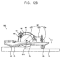
- FIGS. 12A and 12B are side views illustrating traveling states of the traveling robot 800 in FIGS. 8 and 9 . As illustrated in FIGS. 12A and 12B , the traveling robot 800 travels on a traveling surface S formed along a traveling direction “d” and a stair surface O having a stair from the traveling surface S.
- the traveling robot 800 travels along the traveling direction “d,” the front wheel 20 climbs on the stair surface O.
- the wheel frame 610 comprising the driving shaft part 614 is elastically biased by the elastic member 810 of the suspension part 80 .
- the driving wheel 40 is elastically urged to come into maximum contact with the traveling surface S by the elastic member 810 while rotating with respect to the interlocking hinge part 70 .
- the traveling robot 1 As illustrated in FIG. 12B , as the traveling robot 1 further travels along the traveling direction “d,” the driving wheel 40 climbs on the stair surface O, and the rear wheel 50 remains on the traveling surface S. At this time, the driving wheel 40 is elastically urged to come into maximum contact with the traveling surface S by the elastic member 810 while rotating with respect to the interlocking hinge part 70 .
- FIG. 13 is a side view illustrating another traveling state of the traveling robot 800 in FIG. 8 .
- a front wheel 20 and a rear wheel 50 of the traveling robot 800 travel on the stair surface O, but the driving wheel 40 travels on the traveling surface S.
- the wheel frame 60 rotates about the interlocking hinge part 70 with respect to the main body frame 10 in a direction “c.”)
- the driving wheel 40 may additionally protrude toward the traveling surface S from the main body frame 10 to contact the traveling surface S.
- a weight of the main body frame 10 is properly distributed to the front wheel 20 , the driving wheel 40 , and the rear wheel 50 , so that the driving wheel 40 may decrease in ability to be biased or pressed to the traveling surface S.
- the driving wheel 40 is further urged to come into maximum contact with the traveling surface S by the elastic member 810 with respect to the interlocking hinge part 70 .
- the traveling robot according to the present general inventive concept can maintain the sufficient traction force of the driving wheel and minimize shaking of the traveling robot, and thereby enhancing the traveling ability thereof on the uneven surface formed with the stair or the like, since the driving wheel and the rear wheel interlock each other and the opposite traveling parts drive independently to be suitably adapted to the surface.
- suspension part is provided between the main body and the driving wheel, so that the driving wheel is elastically biased toward the traveling surface, thereby allowing the driving wheel to have the maximum ability to be stuck to the ground regardless of whether the weight center of the traveling robot moves or not.
- the elastic member of the suspension part absorbs a shock of the driving wheel colliding with the traveling surface after climbing the stair surface, thereby protecting internal elements of the main body.
Abstract
Description
Claims (16)
Applications Claiming Priority (6)
| Application Number | Priority Date | Filing Date | Title |
|---|---|---|---|
| KR10-2005-0114918 | 2005-11-29 | ||
| KR2005-114918 | 2005-11-29 | ||
| KR1020050114918A KR100670201B1 (en) | 2005-11-29 | 2005-11-29 | Traveling robot |
| KR10-2006-0040566 | 2006-05-04 | ||
| KR1020060040566A KR100757842B1 (en) | 2006-05-04 | 2006-05-04 | Traveling robot |
| KR2006-40566 | 2006-05-04 |
Publications (2)
| Publication Number | Publication Date |
|---|---|
| US20070119635A1 US20070119635A1 (en) | 2007-05-31 |
| US7721829B2 true US7721829B2 (en) | 2010-05-25 |
Family
ID=38038640
Family Applications (1)
| Application Number | Title | Priority Date | Filing Date |
|---|---|---|---|
| US11/601,706 Expired - Fee Related US7721829B2 (en) | 2005-11-29 | 2006-11-20 | Traveling robot |
Country Status (2)
| Country | Link |
|---|---|
| US (1) | US7721829B2 (en) |
| EP (1) | EP1806209A3 (en) |
Cited By (33)
| Publication number | Priority date | Publication date | Assignee | Title |
|---|---|---|---|---|
| US20120181099A1 (en) * | 2011-01-18 | 2012-07-19 | Samsung Electronics Co., Ltd. | Robot cleaner |
| US20130056290A1 (en) * | 2011-09-01 | 2013-03-07 | Samsung Electronics Co., Ltd. | Driving wheel assembly and robot cleaner having the same |
| US9526391B2 (en) | 2011-09-01 | 2016-12-27 | Samsung Electronics Co., Ltd. | Cleaning system and maintenance station thereof |
| US9811089B2 (en) | 2013-12-19 | 2017-11-07 | Aktiebolaget Electrolux | Robotic cleaning device with perimeter recording function |
| US9939529B2 (en) | 2012-08-27 | 2018-04-10 | Aktiebolaget Electrolux | Robot positioning system |
| US9946263B2 (en) | 2013-12-19 | 2018-04-17 | Aktiebolaget Electrolux | Prioritizing cleaning areas |
| US10045675B2 (en) | 2013-12-19 | 2018-08-14 | Aktiebolaget Electrolux | Robotic vacuum cleaner with side brush moving in spiral pattern |
| US10149589B2 (en) | 2013-12-19 | 2018-12-11 | Aktiebolaget Electrolux | Sensing climb of obstacle of a robotic cleaning device |
| US10209080B2 (en) | 2013-12-19 | 2019-02-19 | Aktiebolaget Electrolux | Robotic cleaning device |
| US10219665B2 (en) | 2013-04-15 | 2019-03-05 | Aktiebolaget Electrolux | Robotic vacuum cleaner with protruding sidebrush |
| US10231591B2 (en) | 2013-12-20 | 2019-03-19 | Aktiebolaget Electrolux | Dust container |
| US10433697B2 (en) | 2013-12-19 | 2019-10-08 | Aktiebolaget Electrolux | Adaptive speed control of rotating side brush |
| US10448794B2 (en) | 2013-04-15 | 2019-10-22 | Aktiebolaget Electrolux | Robotic vacuum cleaner |
| US20190366787A1 (en) * | 2018-05-30 | 2019-12-05 | Ubtech Robotics Corp | Suspension system, and chassis and robot with the same |
| US10499778B2 (en) | 2014-09-08 | 2019-12-10 | Aktiebolaget Electrolux | Robotic vacuum cleaner |
| US10518416B2 (en) | 2014-07-10 | 2019-12-31 | Aktiebolaget Electrolux | Method for detecting a measurement error in a robotic cleaning device |
| US10534367B2 (en) | 2014-12-16 | 2020-01-14 | Aktiebolaget Electrolux | Experience-based roadmap for a robotic cleaning device |
| US10617271B2 (en) | 2013-12-19 | 2020-04-14 | Aktiebolaget Electrolux | Robotic cleaning device and method for landmark recognition |
| US10678251B2 (en) | 2014-12-16 | 2020-06-09 | Aktiebolaget Electrolux | Cleaning method for a robotic cleaning device |
| US10729297B2 (en) | 2014-09-08 | 2020-08-04 | Aktiebolaget Electrolux | Robotic vacuum cleaner |
| US10780929B2 (en) * | 2017-04-14 | 2020-09-22 | Exotec Solutions | Automated guided trolley for the transport and/or handling of a load |
| US10877484B2 (en) | 2014-12-10 | 2020-12-29 | Aktiebolaget Electrolux | Using laser sensor for floor type detection |
| US10874274B2 (en) | 2015-09-03 | 2020-12-29 | Aktiebolaget Electrolux | System of robotic cleaning devices |
| US10874271B2 (en) | 2014-12-12 | 2020-12-29 | Aktiebolaget Electrolux | Side brush and robotic cleaner |
| US11099554B2 (en) | 2015-04-17 | 2021-08-24 | Aktiebolaget Electrolux | Robotic cleaning device and a method of controlling the robotic cleaning device |
| US11122953B2 (en) | 2016-05-11 | 2021-09-21 | Aktiebolaget Electrolux | Robotic cleaning device |
| US11148696B2 (en) | 2018-12-27 | 2021-10-19 | Toyota Research Institute, Inc. | Assistive robots including assemblies for accommodating obstacles and methods for using the same |
| US11169533B2 (en) | 2016-03-15 | 2021-11-09 | Aktiebolaget Electrolux | Robotic cleaning device and a method at the robotic cleaning device of performing cliff detection |
| US11420338B2 (en) | 2018-12-27 | 2022-08-23 | Toyota Research Institute, Inc. | Assistive robot systems for container tilting |
| US11474533B2 (en) | 2017-06-02 | 2022-10-18 | Aktiebolaget Electrolux | Method of detecting a difference in level of a surface in front of a robotic cleaning device |
| US11505017B2 (en) | 2018-12-27 | 2022-11-22 | Toyota Research Institute, Inc. | Devices including deployable hitch assemblies and autonomous engagement systems incorporating the same |
| US11827500B2 (en) | 2018-12-27 | 2023-11-28 | Toyota Research Institute, Inc. | Assistive robot systems for transporting containers |
| US11921517B2 (en) | 2017-09-26 | 2024-03-05 | Aktiebolaget Electrolux | Controlling movement of a robotic cleaning device |
Families Citing this family (4)
| Publication number | Priority date | Publication date | Assignee | Title |
|---|---|---|---|---|
| KR20090028359A (en) * | 2007-09-14 | 2009-03-18 | 삼성광주전자 주식회사 | A wheel-driving assembly for a moving apparatus |
| US10245935B2 (en) * | 2015-09-17 | 2019-04-02 | Clearpath Robotics, Inc. | Mobile platform for materials transport |
| CN105598940A (en) * | 2016-03-18 | 2016-05-25 | 昆山市工业技术研究院有限责任公司 | Patrol robot |
| US11148698B2 (en) | 2018-08-21 | 2021-10-19 | Clearpath Robotics Inc. | Materials handling cart |
Citations (16)
| Publication number | Priority date | Publication date | Assignee | Title |
|---|---|---|---|---|
| JPS57186589A (en) | 1981-05-08 | 1982-11-17 | Shinko Electric Co Ltd | Four-wheeled vehicle |
| US4515235A (en) * | 1982-05-25 | 1985-05-07 | Shinko Electric Co., Ltd. | Driverless guided vehicle |
| US4572311A (en) * | 1982-08-20 | 1986-02-25 | Oswald Norman D | Walking beam arrangement for adverse terrain vehicle |
| US5350033A (en) * | 1993-04-26 | 1994-09-27 | Kraft Brett W | Robotic inspection vehicle |
| EP0402764B1 (en) | 1989-06-07 | 1996-01-10 | Kabushiki Kaisha Toshiba | Control apparatus for plane working robot |
| JP2000202792A (en) | 1999-01-14 | 2000-07-25 | Sharp Corp | Cleaning robot |
| JP2000279353A (en) | 1999-03-29 | 2000-10-10 | Fuji Heavy Ind Ltd | Position adjusting mechanism of dust suction device in floor surface cleaning robot |
| US6357076B1 (en) * | 1999-10-27 | 2002-03-19 | Samsung Kwang-Ju Electronics Co., Ltd. | Suction nozzle unit for vacuum cleaner |
| US20020153184A1 (en) * | 2001-04-18 | 2002-10-24 | Jeong-Gon Song | Robot cleaner, robot cleaning system and method for controlling same |
| US20030028993A1 (en) * | 2001-08-07 | 2003-02-13 | Jeong-Gon Song | Robot cleaner, system thereof and method for controlling same |
| KR20040008373A (en) | 2002-07-18 | 2004-01-31 | 한국과학기술연구원 | 4-bar passive linkage-type locomotive mechanism of six-wheeled mobile robot capable of climbing up stairs |
| US20040195012A1 (en) * | 2003-04-04 | 2004-10-07 | Samsung Gwangju Electronics Co., Ltd. | Driving apparatus for a robot cleaner |
| KR20040096253A (en) | 2003-05-07 | 2004-11-16 | 엘지전자 주식회사 | Wheel assembly for robot vacuum cleaner |
| US20040262060A1 (en) * | 2003-06-30 | 2004-12-30 | Samsung Gwangju Electronics Co., Ltd. | Driving device for robot cleaner |
| KR20050015018A (en) | 2003-08-01 | 2005-02-21 | 삼성전자주식회사 | Mobile robot |
| US20070137905A1 (en) * | 2005-12-02 | 2007-06-21 | Youn-Baek Lee | Traveling robot |
Family Cites Families (4)
| Publication number | Priority date | Publication date | Assignee | Title |
|---|---|---|---|---|
| GB1578742A (en) * | 1976-02-24 | 1980-11-12 | Nat Res Dev | Peripatetic vehicles |
| SE450366B (en) * | 1986-04-09 | 1987-06-22 | Magnus Rikard Frost | WHEEL CHASSIS |
| JP2769636B2 (en) * | 1989-12-16 | 1998-06-25 | 株式会社スター精機 | Driverless car |
| JP2000351385A (en) * | 1999-06-10 | 2000-12-19 | Ishikawajima Harima Heavy Ind Co Ltd | Automatically guided vehicle |
-
2006
- 2006-11-20 US US11/601,706 patent/US7721829B2/en not_active Expired - Fee Related
- 2006-11-24 EP EP06124735A patent/EP1806209A3/en not_active Withdrawn
Patent Citations (19)
| Publication number | Priority date | Publication date | Assignee | Title |
|---|---|---|---|---|
| JPS57186589A (en) | 1981-05-08 | 1982-11-17 | Shinko Electric Co Ltd | Four-wheeled vehicle |
| US4515235A (en) * | 1982-05-25 | 1985-05-07 | Shinko Electric Co., Ltd. | Driverless guided vehicle |
| US4572311A (en) * | 1982-08-20 | 1986-02-25 | Oswald Norman D | Walking beam arrangement for adverse terrain vehicle |
| EP0402764B1 (en) | 1989-06-07 | 1996-01-10 | Kabushiki Kaisha Toshiba | Control apparatus for plane working robot |
| US5350033A (en) * | 1993-04-26 | 1994-09-27 | Kraft Brett W | Robotic inspection vehicle |
| JP2000202792A (en) | 1999-01-14 | 2000-07-25 | Sharp Corp | Cleaning robot |
| JP2000279353A (en) | 1999-03-29 | 2000-10-10 | Fuji Heavy Ind Ltd | Position adjusting mechanism of dust suction device in floor surface cleaning robot |
| US6357076B1 (en) * | 1999-10-27 | 2002-03-19 | Samsung Kwang-Ju Electronics Co., Ltd. | Suction nozzle unit for vacuum cleaner |
| US20020153184A1 (en) * | 2001-04-18 | 2002-10-24 | Jeong-Gon Song | Robot cleaner, robot cleaning system and method for controlling same |
| US20030028993A1 (en) * | 2001-08-07 | 2003-02-13 | Jeong-Gon Song | Robot cleaner, system thereof and method for controlling same |
| KR20040008373A (en) | 2002-07-18 | 2004-01-31 | 한국과학기술연구원 | 4-bar passive linkage-type locomotive mechanism of six-wheeled mobile robot capable of climbing up stairs |
| US20040195012A1 (en) * | 2003-04-04 | 2004-10-07 | Samsung Gwangju Electronics Co., Ltd. | Driving apparatus for a robot cleaner |
| KR20040087185A (en) | 2003-04-04 | 2004-10-13 | 삼성광주전자 주식회사 | Driving unit for robot cleaner |
| KR20040096253A (en) | 2003-05-07 | 2004-11-16 | 엘지전자 주식회사 | Wheel assembly for robot vacuum cleaner |
| US20040262060A1 (en) * | 2003-06-30 | 2004-12-30 | Samsung Gwangju Electronics Co., Ltd. | Driving device for robot cleaner |
| KR20050003112A (en) | 2003-06-30 | 2005-01-10 | 삼성광주전자 주식회사 | Device for driving of robot cleaner |
| US7213663B2 (en) * | 2003-06-30 | 2007-05-08 | Samsung Gwangju Electronics Co., Ltd. | Driving device for robot cleaner |
| KR20050015018A (en) | 2003-08-01 | 2005-02-21 | 삼성전자주식회사 | Mobile robot |
| US20070137905A1 (en) * | 2005-12-02 | 2007-06-21 | Youn-Baek Lee | Traveling robot |
Non-Patent Citations (1)
| Title |
|---|
| Korean Office Action dated May 7, 2007 issued in KR 2006-0040566. |
Cited By (37)
| Publication number | Priority date | Publication date | Assignee | Title |
|---|---|---|---|---|
| US20120181099A1 (en) * | 2011-01-18 | 2012-07-19 | Samsung Electronics Co., Ltd. | Robot cleaner |
| US20130056290A1 (en) * | 2011-09-01 | 2013-03-07 | Samsung Electronics Co., Ltd. | Driving wheel assembly and robot cleaner having the same |
| US9241602B2 (en) * | 2011-09-01 | 2016-01-26 | Samsung Electronics Co., Ltd. | Driving wheel assembly and robot cleaner having the same |
| US9526391B2 (en) | 2011-09-01 | 2016-12-27 | Samsung Electronics Co., Ltd. | Cleaning system and maintenance station thereof |
| US9939529B2 (en) | 2012-08-27 | 2018-04-10 | Aktiebolaget Electrolux | Robot positioning system |
| US10219665B2 (en) | 2013-04-15 | 2019-03-05 | Aktiebolaget Electrolux | Robotic vacuum cleaner with protruding sidebrush |
| US10448794B2 (en) | 2013-04-15 | 2019-10-22 | Aktiebolaget Electrolux | Robotic vacuum cleaner |
| US10617271B2 (en) | 2013-12-19 | 2020-04-14 | Aktiebolaget Electrolux | Robotic cleaning device and method for landmark recognition |
| US9811089B2 (en) | 2013-12-19 | 2017-11-07 | Aktiebolaget Electrolux | Robotic cleaning device with perimeter recording function |
| US10209080B2 (en) | 2013-12-19 | 2019-02-19 | Aktiebolaget Electrolux | Robotic cleaning device |
| US10045675B2 (en) | 2013-12-19 | 2018-08-14 | Aktiebolaget Electrolux | Robotic vacuum cleaner with side brush moving in spiral pattern |
| US10433697B2 (en) | 2013-12-19 | 2019-10-08 | Aktiebolaget Electrolux | Adaptive speed control of rotating side brush |
| US9946263B2 (en) | 2013-12-19 | 2018-04-17 | Aktiebolaget Electrolux | Prioritizing cleaning areas |
| US10149589B2 (en) | 2013-12-19 | 2018-12-11 | Aktiebolaget Electrolux | Sensing climb of obstacle of a robotic cleaning device |
| US10231591B2 (en) | 2013-12-20 | 2019-03-19 | Aktiebolaget Electrolux | Dust container |
| US10518416B2 (en) | 2014-07-10 | 2019-12-31 | Aktiebolaget Electrolux | Method for detecting a measurement error in a robotic cleaning device |
| US10499778B2 (en) | 2014-09-08 | 2019-12-10 | Aktiebolaget Electrolux | Robotic vacuum cleaner |
| US10729297B2 (en) | 2014-09-08 | 2020-08-04 | Aktiebolaget Electrolux | Robotic vacuum cleaner |
| US10877484B2 (en) | 2014-12-10 | 2020-12-29 | Aktiebolaget Electrolux | Using laser sensor for floor type detection |
| US10874271B2 (en) | 2014-12-12 | 2020-12-29 | Aktiebolaget Electrolux | Side brush and robotic cleaner |
| US10534367B2 (en) | 2014-12-16 | 2020-01-14 | Aktiebolaget Electrolux | Experience-based roadmap for a robotic cleaning device |
| US10678251B2 (en) | 2014-12-16 | 2020-06-09 | Aktiebolaget Electrolux | Cleaning method for a robotic cleaning device |
| US11099554B2 (en) | 2015-04-17 | 2021-08-24 | Aktiebolaget Electrolux | Robotic cleaning device and a method of controlling the robotic cleaning device |
| US11712142B2 (en) | 2015-09-03 | 2023-08-01 | Aktiebolaget Electrolux | System of robotic cleaning devices |
| US10874274B2 (en) | 2015-09-03 | 2020-12-29 | Aktiebolaget Electrolux | System of robotic cleaning devices |
| US11169533B2 (en) | 2016-03-15 | 2021-11-09 | Aktiebolaget Electrolux | Robotic cleaning device and a method at the robotic cleaning device of performing cliff detection |
| US11122953B2 (en) | 2016-05-11 | 2021-09-21 | Aktiebolaget Electrolux | Robotic cleaning device |
| US10780929B2 (en) * | 2017-04-14 | 2020-09-22 | Exotec Solutions | Automated guided trolley for the transport and/or handling of a load |
| US11474533B2 (en) | 2017-06-02 | 2022-10-18 | Aktiebolaget Electrolux | Method of detecting a difference in level of a surface in front of a robotic cleaning device |
| US11921517B2 (en) | 2017-09-26 | 2024-03-05 | Aktiebolaget Electrolux | Controlling movement of a robotic cleaning device |
| US10875371B2 (en) * | 2018-05-30 | 2020-12-29 | Ubtech Robotics Corp | Suspension system, and chassis and robot with the same |
| US20190366787A1 (en) * | 2018-05-30 | 2019-12-05 | Ubtech Robotics Corp | Suspension system, and chassis and robot with the same |
| US11148696B2 (en) | 2018-12-27 | 2021-10-19 | Toyota Research Institute, Inc. | Assistive robots including assemblies for accommodating obstacles and methods for using the same |
| US11420338B2 (en) | 2018-12-27 | 2022-08-23 | Toyota Research Institute, Inc. | Assistive robot systems for container tilting |
| US11505017B2 (en) | 2018-12-27 | 2022-11-22 | Toyota Research Institute, Inc. | Devices including deployable hitch assemblies and autonomous engagement systems incorporating the same |
| US11597098B2 (en) | 2018-12-27 | 2023-03-07 | Toyota Research Institute, Inc. | Assistive robot systems for container lifting |
| US11827500B2 (en) | 2018-12-27 | 2023-11-28 | Toyota Research Institute, Inc. | Assistive robot systems for transporting containers |
Also Published As
| Publication number | Publication date |
|---|---|
| EP1806209A2 (en) | 2007-07-11 |
| EP1806209A3 (en) | 2011-07-27 |
| US20070119635A1 (en) | 2007-05-31 |
Similar Documents
| Publication | Publication Date | Title |
|---|---|---|
| US7721829B2 (en) | Traveling robot | |
| US7673710B2 (en) | Traveling robot | |
| JP4607442B2 (en) | Crawler type traveling robot | |
| US5894621A (en) | Unmanned working vehicle | |
| JP6902728B2 (en) | Mobile | |
| US9009915B2 (en) | Upright type vacuum cleaner | |
| KR101272197B1 (en) | Travelling device of rover | |
| KR100757842B1 (en) | Traveling robot | |
| KR100670201B1 (en) | Traveling robot | |
| US11932052B2 (en) | Driving apparatus maintaining ground contact of drive-wheel | |
| US10631694B2 (en) | Autonomous cleaner | |
| KR20090043383A (en) | An wheel connection apparatus and a cleaner having the same | |
| WO2007149255A2 (en) | Suspension for a telepresence robot | |
| US11712140B2 (en) | Robot cleaner | |
| KR101617957B1 (en) | Vacuum cleaner | |
| JPH0781696A (en) | Off-road travel car | |
| JP3981755B2 (en) | Electric transporter | |
| CN111655101A (en) | Robot cleaner | |
| CN114668350B (en) | Running gear and cleaning device | |
| US11713081B2 (en) | Vehicle body | |
| KR102486418B1 (en) | Multipurpose vehicle capable of driving on the ground and walls | |
| JPH10324210A (en) | Tumble protecting frame of tractor | |
| CN210101811U (en) | Passive self-adaptive robot | |
| US20220386833A1 (en) | Robot cleaner | |
| JP2002145411A (en) | Moving shelf device |
Legal Events
| Date | Code | Title | Description |
|---|---|---|---|
| AS | Assignment |
Owner name: SAMSUNG ELECTRONICS CO., LTD.,KOREA, REPUBLIC OF Free format text: ASSIGNMENT OF ASSIGNORS INTEREST;ASSIGNORS:LEE, YOUN-BAEK;YANG, SOO-SANG;KIM YONG-JAE;AND OTHERS;REEL/FRAME:018620/0146 Effective date: 20061115 Owner name: SAMSUNG ELECTRONICS CO., LTD., KOREA, REPUBLIC OF Free format text: ASSIGNMENT OF ASSIGNORS INTEREST;ASSIGNORS:LEE, YOUN-BAEK;YANG, SOO-SANG;KIM YONG-JAE;AND OTHERS;REEL/FRAME:018620/0146 Effective date: 20061115 |
|
| STCF | Information on status: patent grant |
Free format text: PATENTED CASE |
|
| FEPP | Fee payment procedure |
Free format text: PAYOR NUMBER ASSIGNED (ORIGINAL EVENT CODE: ASPN); ENTITY STATUS OF PATENT OWNER: LARGE ENTITY |
|
| FEPP | Fee payment procedure |
Free format text: PAYER NUMBER DE-ASSIGNED (ORIGINAL EVENT CODE: RMPN); ENTITY STATUS OF PATENT OWNER: LARGE ENTITY Free format text: PAYOR NUMBER ASSIGNED (ORIGINAL EVENT CODE: ASPN); ENTITY STATUS OF PATENT OWNER: LARGE ENTITY |
|
| FPAY | Fee payment |
Year of fee payment: 4 |
|
| MAFP | Maintenance fee payment |
Free format text: PAYMENT OF MAINTENANCE FEE, 8TH YEAR, LARGE ENTITY (ORIGINAL EVENT CODE: M1552) Year of fee payment: 8 |
|
| FEPP | Fee payment procedure |
Free format text: MAINTENANCE FEE REMINDER MAILED (ORIGINAL EVENT CODE: REM.); ENTITY STATUS OF PATENT OWNER: LARGE ENTITY |
|
| LAPS | Lapse for failure to pay maintenance fees |
Free format text: PATENT EXPIRED FOR FAILURE TO PAY MAINTENANCE FEES (ORIGINAL EVENT CODE: EXP.); ENTITY STATUS OF PATENT OWNER: LARGE ENTITY |
|
| STCH | Information on status: patent discontinuation |
Free format text: PATENT EXPIRED DUE TO NONPAYMENT OF MAINTENANCE FEES UNDER 37 CFR 1.362 |
|
| STCH | Information on status: patent discontinuation |
Free format text: PATENT EXPIRED DUE TO NONPAYMENT OF MAINTENANCE FEES UNDER 37 CFR 1.362 |
|
| FP | Lapsed due to failure to pay maintenance fee |
Effective date: 20220525 |