US7714930B2 - Control method for digital photographing apparatus for efficient setting operation and digital photographing apparatus using the method - Google Patents
Control method for digital photographing apparatus for efficient setting operation and digital photographing apparatus using the method Download PDFInfo
- Publication number
- US7714930B2 US7714930B2 US11/029,189 US2918905A US7714930B2 US 7714930 B2 US7714930 B2 US 7714930B2 US 2918905 A US2918905 A US 2918905A US 7714930 B2 US7714930 B2 US 7714930B2
- Authority
- US
- United States
- Prior art keywords
- button
- setting signal
- operating mode
- mode
- generated
- Prior art date
- Legal status (The legal status is an assumption and is not a legal conclusion. Google has not performed a legal analysis and makes no representation as to the accuracy of the status listed.)
- Expired - Fee Related, expires
Links
Images


Classifications
-
- H—ELECTRICITY
- H04—ELECTRIC COMMUNICATION TECHNIQUE
- H04N—PICTORIAL COMMUNICATION, e.g. TELEVISION
- H04N23/00—Cameras or camera modules comprising electronic image sensors; Control thereof
- H04N23/60—Control of cameras or camera modules
- H04N23/667—Camera operation mode switching, e.g. between still and video, sport and normal or high- and low-resolution modes
-
- H—ELECTRICITY
- H04—ELECTRIC COMMUNICATION TECHNIQUE
- H04N—PICTORIAL COMMUNICATION, e.g. TELEVISION
- H04N23/00—Cameras or camera modules comprising electronic image sensors; Control thereof
Definitions
- the present invention relates to a control method for a digital photographing apparatus, a digital photographing apparatus using the method, and a system for controlling the operation of a digital photographing apparatus. More particularly, the present invention relates to a control method for a digital photographing apparatus in which one of the operating modes associated with a button is set according to operation of the button, a digital photographing apparatus using the method, and a system for setting the operating mode of a digital photographing apparatus.
- a conventional digital photographing apparatus was disclosed by the present applicant in U.S. Patent Publication No. 119,876, “Method of Notification of Inadequate Picture Quality.”
- one of the operating modes associated with a button for example, a flash button, is set according to the number of times that the button is pressed. Generally, whenever the button is pressed, a next operating mode in a forward direction is displayed and set. Therefore, if the user mistakenly skips a desired operating mode, the user has to press the button as many times as the number of operating modes in order to return to the desired operating mode.
- the present invention provides a control method for a digital photographing apparatus.
- the control method herein described enables a user to set an operating mode quickly and easily.
- the present invention also provides a digital photographing apparatus which employs the method.
- a control method for a digital photographing apparatus in which one of the operating modes associated with a button is set according to the number of times the button is pressed.
- the method includes (1) setting a next operating mode in a forward direction if a first setting signal is generated by pressing the button and (2) setting a next operating mode in a reverse direction if a second setting signal including the first setting signal is generated by pressing the button.
- a user may set a next operating mode in a forward or reverse direction using the button. Therefore, even if the user mistakenly skips a desired flash mode, the desired flash mode can be set quickly and easily by pressing the button.
- FIG. 1 is a perspective view showing the front and the top of a digital photographing apparatus according to the present invention
- FIG. 2 is a back view showing the back of the digital photographing apparatus of FIG. 1 ;
- FIG. 3 is a schematic diagram of the configuration of the digital photographing apparatus of FIG. 1 ;
- FIG. 4 is a flowchart illustrating a main algorithm of a digital signal processor (DSP) illustrated in FIG. 3 ;
- DSP digital signal processor
- FIG. 5 is a flowchart illustrating a preview mode algorithm illustrated in FIG. 4 ;
- FIG. 6 illustrates a still-image photographing mode algorithm illustrated in FIG. 4 ;
- FIG. 7 is a flowchart illustrating a moving-image photographing mode algorithm illustrated in FIG. 4 ;
- FIG. 8 is a flowchart illustrating a flash-mode setting algorithm performed when a flash/left button is pressed in operation S 5 of FIG. 4 according to an embodiment of the present invention
- FIG. 9 is a color LCD panel displaying an icon of a flash mode currently set as a result of performing operation S 691 illustrated in FIG. 8 ;
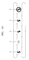
- FIG. 10 summarizes the flash mode setting algorithm of FIG. 8 ;
- FIG. 11 is a flowchart illustrating a reproducing mode algorithm illustrated in FIG. 4 ;
- FIG. 12 is a flowchart illustrating a flash-mode setting algorithm when the flash/left button is pressed in S 5 of FIG. 4 according to another embodiment of the present invention.
- the front part of a digital camera 1 includes a microphone MIC, a self-timer lamp 11 , a flash 12 , a shutter release button 13 , a viewfinder 17 a , a flash light intensity sensor 19 , a power switch 31 , a lens unit 20 , and a remote receiver 41 .
- the self-timer lamp 11 operates for a set period of time from the time when the shutter release button 13 is pressed to the time when an image starts to be captured.
- the flash light intensity sensor 19 senses the intensity of the light generated by the flash 12 and relays the sensed intensity of the light to a digital signal processor (DSP) 507 of FIG. 3 via a micro-controller 512 of FIG. 3 .
- DSP digital signal processor
- the remote receiver 41 receives command signals, such as a photographing command signal, and relays the command signals to the micro-controller 512 .
- the shutter release button 13 has two levels. In other words, after operating a wide angle-zoom button 39 W of FIG. 2 and a telephoto-zoom button 39 T of FIG. 2 , when a user lightly depresses the shutter release button 13 to a first level, a first level signal S 1 from the shutter release button 13 is turned on. When the user fully depresses the shutter release button 13 to a second level, a second level signal S 2 of the shutter release button 13 is turned on (see FIGS. 4 , 6 and 7 ).
- the back of the digital camera 1 includes a mode dial 14 , functional buttons 15 , a manual focusing/deleting button 36 , a manual adjusting/reproducing/terminating button 37 , a reproducing mode button 42 , a speaker SP, a monitor button 32 , an automatic focusing lamp 33 , a viewfinder 17 b , a flash standby lamp 34 , a color LCD panel 35 , the wide angle-zoom button 39 W , the telephoto-zoom button 39 T , and an external interface unit 21 .
- the mode dial 14 is used for selecting any one of the operating modes of the digital camera 1 .
- Exemplary operating modes include the following: a simple photographing mode, a program photographing mode, a character photographing mode, a night view photographing mode, a manual photographing mode, a moving-image photographing mode 14 MP , a user setting mode 14 MY , and a recording mode 14 V .
- the user setting mode 14 MY is an operating mode in which the user selects the photograph-taking settings for a still-image or moving-image photographing mode.
- the recording mode 14 V is for recording only sounds, e.g., a user's voice. After selecting the recording mode 14 V , when a user presses the shutter release button, an audio file is created in the memory card and audio data is stored in the audio file. When the user presses the shutter release button 13 again, the audio data stops being stored and the audio file is set.
- the functional buttons 15 are used for operating specific functions of the digital camera 1 , and the functional buttons 15 are also used as control buttons to manage the movement of an active cursor on the menu screen of the color LCD panel 35 .
- a reproducing mode if an image currently displayed is not enlarged, when a user presses a self-timer/right button 15 R , a next file in a forward direction is displayed. If an image currently displayed is enlarged, when the user presses the self-timer/right button 15 R , a display region of the enlarged image is moved to the right.
- a self-timer operation e.g., automatic photographing after 10 seconds, is performed.
- the reproducing mode if the image currently displayed is not enlarged, when the user presses a flash/left button 15 L , a next file in a reverse direction is displayed. If the image currently displayed is enlarged, when the user presses the flash/left button 15 L , the display region of the enlarged image is moved to the left.
- any one of the flash modes for a photographing mode is set. If the flash/left button 15 L is pressed is for a period of time equal to or shorter than a reference time, a next flash mode in the reverse direction is set. In other words, if the user presses the flash/left button 15 L for a short time, a next flash mode in the forward direction is set, and if the user presses the flash/left button 15 L for a long time, a next flash mode in the reverse direction is set. Therefore, even if the user mistakenly skips a desired flash mode, the desired flash mode can be set quickly and easily by pressing the flash/left button 15 L for a short or long time. A related algorithm will be described later with reference to FIGS. 8 , 9 , and 10 .
- the reproducing mode if the image currently displayed is enlarged, when the user presses a macro/down button 15 D , the display region of the enlarged image is moved down.
- the user may set automatic proximity focusing by pressing a macro/down button 15 D .
- the reproducing mode when the image currently displayed is enlarged, if the user presses a voice-memo/up button 15 U , the display region of the enlarged image is moved up.
- the preview mode if the user presses the voice/memo/up button 15 U , a 10 second recording is possible upon consecutive photographing.
- a setting mode from the preview mode if the user presses a menu/select-confirm button 15 M when the active cursor is on a selection menu, the operation corresponding to the selection menu is performed.
- the manual adjusting/reproducing/terminating button 37 is used for manual adjustment of specific conditions. In addition, when the user presses the manual adjusting/reproducing/terminating button 37 , a selected moving-image file may be reproduced or its reproduction may be terminated.
- the manual focusing/deleting button 36 is used for manual focusing or deleting in the photographing mode.
- the monitor button 32 is used for controlling the operation of the color LCD panel 35 .
- the photographing mode when the user presses the monitor button 32 , an image and photographing information are displayed on the color LCD panel 35 .
- the color LCD panel 35 is turned off.
- the reproducing mode when the user presses the monitor button 32 while an image file is being reproduced, photographing information about the image file is displayed on the color LCD panel 35 .
- the monitor button 32 again only pure images are displayed.
- the reproducing mode button 42 is used for switching between a reproducing mode and a preview mode.
- the automatic focusing lamp 33 operates when a focus is well adjusted.
- the flash standby lamp 34 operates when the flash 12 of FIG. 1 is in a standby mode.
- a mode indicating lamp 14 L indicates a selection mode of the mode dial 14 .
- FIG. 3 is a schematic diagram of the configuration of the digital camera of FIG. 1 .
- the configuration and operation of the digital camera 1 of FIG. 1 will now be described with reference to FIGS. 1 through 3 .
- An optical system including the lens unit 20 and a filter unit optically processes light.
- the lens unit 20 of the OPS includes a zoom lens, a focus lens, and a compensation lens.
- a signal corresponding to the wide angle-zoom button 39 W or the telephoto-zoom button 39 T is relayed to the micro-controller 512 .
- the micro-controller 512 controls a lens driver 510 , thereby running a zoom motor M Z , which in turn, moves the zoom lens.
- the focal length of the zoom lens becomes short, thereby widening the angle of view.
- the telephoto-zoom button 39 T the focal length of the zoom lens becomes long, thereby narrowing the angle of view. Since the position of the focus lens is adjusted in a state where the position of the zoom lens is set, the angle of view is hardly affected by the position of the focus lens.
- a main controller built into the DSP 507 controls the lens driver 510 through the micro-controller 512 , thereby driving a focus motor M F . Accordingly, when the focus lens is moved, the position of the focus lens having the largest high frequency component of an image signal is set.
- the position of the focus lens may be determined, for example, by the number of driving steps of the focus motor M F .
- a compensation lens in the lens unit 20 of the OPS is not separately operated because the compensation lens compensates for the entire refractive index.
- Reference numeral M A indicates a motor for driving an aperture (not shown).
- An optical low pass filter included in the filter unit of the OPS eliminates high frequency optical noise.
- An infrared cut filter included in the filter unit of the OPS blocks the infrared component of incident light.
- a photoelectric conversion unit (OEC) of a charge coupled device or a complementary metal oxide (CMOS) semiconductor converts light from the OPS into an analog electrical signal.
- the DSP 507 controls a timing circuit 502 to control the operations of the OEC and a correlation-double-sampler-and-analog-to-digital converter (CDS-ADC) 501 .
- the CDS-ADC 501 processes an analog signal from the OEC, eliminates high frequency noise, adjusts amplitude, and then converts the analog signal into a digital signal.
- a real time clock (RTC) 503 provides time information to the DSP 507 .
- the DSP 507 processes the digital signal from the CDS-ADC 501 and generates a digital image composed of luminance and chromaticity values.
- a light source is operated by the micro-controller 512 in response to a control signal generated by the DSP 507 including the main controller.
- the light source (LAMP) includes the self-timer lamp 11 , the automatic focusing lamp 33 , the mode indicating lamp 14 L , and the flash standby lamp 34 .
- the INP includes the shutter release button 13 , the mode dial 14 , the functional buttons 15 , the monitor button 32 , the manual focusing/deleting button 36 , the manual adjusting/reproducing/terminating button 37 , the wide angle-zoom button 39 W , and the telephoto-zoom button 39 T , and the reproducing mode button 42 .
- a dynamic random access memory (DRAM) 504 temporarily stores a digital image signal from the DSP 507 .
- An electrically erasable and programmable read only memory (EEPROM) 505 stores algorithm and setting data.
- a user's memory card is inserted or removed in a memory card interface (MCI) 506 .
- the digital image signal from the DSP 507 is input to an LCD driver 514 , thereby displaying an image on the color LCD panel 35 .
- the digital image signal from the DSP 507 can be transmitted via a universal serial bus (USB) connector 21 a or via an RS232C interface 508 and an RS232C connector 21 b for serial communications.
- the digital image signal from the DSP 507 can also be transmitted via a video filter 509 and a video output unit 21 c as a video signal.
- the DSP 507 includes the main controller.
- An audio processor 513 can relay sound from the microphone MIC to the DSP 507 or to speaker SP. In addition, the audio processor 513 can output an audio signal from the DSP 507 to the speaker SP.
- the micro-controller 512 controls the operation of a flash controller 511 in response to a signal from the flash light intensity sensor (FS) 19 , thereby driving the flash 12 .
- FS flash light intensity sensor
- the DSP 507 When power is applied to the digital photographing apparatus 1 , the DSP 507 is initialized (S 1 ). After the initialization (S 1 ), the DSP 507 performs a preview mode (S 2 ). In the preview mode, an image input is displayed on the display panel 35 . An operation related to the preview mode will be described in detail later with reference to FIG. 5 .
- the DSP 507 When the first level signal S 1 from the shutter release button 13 is on after a user pressed the shutter release button 13 to the first level, the DSP 507 identifies a current operating mode (S 32 ). Hereinafter, a description of the recording mode will be omitted.
- the DSP 507 performs the still-image photographing mode or the moving-image photographing mode depending on the chosen current operation mode (Steps S 41 or S 42 ).
- the still-image photographing mode (S 41 ) algorithm will be described with reference to FIG. 6 .
- the moving-image photographing mode (S 42 ) algorithm will be described with reference to FIG. 7 .
- the setting mode for setting an operating condition in response to the input signals from the INP is performed (S 6 ).
- the setting mode for setting one of the flash modes is performed (S 6 ).
- An algorithm of the setting mode for setting a flash mode (S 6 F of FIG. 8 ) will be described later in detail with reference to FIGS. 8 , 9 , and 10 .
- the DSP 507 continues to perform the following operation (S 7 ).
- the preview mode (S 2 ) algorithm of FIG. 4 will now be described with reference to FIGS. 1 through 3 and FIG. 5 .
- the DSP 507 performs automatic white balancing (AWB) and sets parameters related to the white balance (S 201 ).
- AVB automatic white balancing
- the DSP 507 calculates the exposure by measuring incident luminance, drives the aperture driving motor M A according to the calculated exposure, and sets a shutter speed (S 203 ).
- the DSP 507 performs gamma correction on input image data (S 204 ) and scales the gamma corrected image data to meet display standards (S 205 ).
- the DSP 507 converts the scaled input image data from an RGB (red, green, and blue) format into a luminance-chrominance format (S 206 ).
- the DSP 507 processes the input image data depending on resolution and display location and also filters the input image data (S 207 ).
- the DSP 507 temporarily stores the input image data in the DRAM 504 of FIG. 3 (S 208 ).
- the DSP 507 synthesizes the data temporarily stored in the DRAM 504 of FIG. 3 and on-screen display (OSD) data (S 209 ).
- the DSP 507 converts the synthesized image data from the RGB format into the luminance-chromaticity format (S 210 ) and outputs the image data in the converted format via the LCD driver 514 of FIG. 3 (S 211 ).
- FIG. 6 illustrates a still-image photographing mode (S 41 ) algorithm illustrated in FIG. 4 .
- the still-image photographing mode (S 41 ) algorithm will now be described with reference to FIGS. 1 through 3 and FIG. 6 .
- the present position of the zoom lens is already set.
- the DSP 507 inspects the remaining capacity of the memory card (S 4101 ) and determines whether the memory card has enough capacity to store a digital image signal (S 4102 ). If the memory card does not have enough storage capacity, the DSP 507 indicates the lack of capacity of the memory card and ends the still-image photographing mode (S 4103 ). If the memory card has enough storage capacity, the following operations are performed.
- the DSP 507 sets white balance and parameters related to the white balance according to a present photographing condition (S 4104 ).
- the DSP 507 calculates the exposure by measuring incident luminance, drives the aperture driving motor M A according to the calculated exposure, and sets the exposure time (S 4106 ).
- the DSP 507 performs automatic focusing and drives the focus lens (S 4108 ).
- the DSP 507 continues to perform the following steps.
- the DSP 507 identifies whether the second level signal S 2 is on (S 4110 ). When the second level signal S 2 is not on, it means that the user did not press the shutter release button 13 to the second level to take a photograph. Then, the DSP 507 repeats the operations S 4105 through S 4110 .
- the DSP 507 When the second level signal S 2 is on, it means that the user pressed the shutter release button 13 to the second level, and the DSP 507 creates a still-image file in the memory card (S 4111 ). Next, the DSP 507 captures a still image (S 4112 ). In other words, the DSP 507 receives still-image data from the CDS-ADC 501 and the DSP 507 compresses the received still-image data (S 4113 ). The DSP 507 stores the compressed still-image data in the still-image file (S 4114 ).
- FIG. 7 is a flowchart illustrating the moving-image photographing mode (S 42 ) algorithm illustrated in FIG. 4 .
- the moving-image photographing mode algorithm will now be described with reference to FIGS. 1 through 3 and FIG. 7 .
- the DSP 507 deletes the OSD data (S 4201 and S 4202 ).
- the DSP 507 inspects the remaining capacity of the memory card and determines whether a storable time for storing digital moving-image data is present (S 4203 ). When the memory card does not have enough storage capacity, the DSP 507 indicates the lack of capacity of the memory card (S 4204 ). When the memory card has enough storage capacity, the following operations are performed.
- the DSP 507 displays a symbol of the moving-image photographing mode and storable time on the LCD panel 35 (S 4205 ).
- the DSP 507 sets a white balance and parameters related to the white balance according to a set photographing condition (S 4206 ). Then, the DSP 507 performs the automatic exposure mode according to the set photographing condition (S 4207 ). In other words, the DSP 507 calculates the exposure by measuring incident luminance, drives the aperture driving motor M A according to the calculated exposure, and sets exposure time. The DSP 507 performs automatic focusing according to the set photographing condition and drives the focus lens (S 4208 ).
- the DSP performs the following operations.
- the DSP 507 determines whether the second level signal S 2 is on (S 4210 ). When the second level signal S 2 is not on, it means that the user did not press the shutter release button 13 to the second level to take a photograph. Therefore, the DSP 507 repeats the operations S 4207 through S 4210 .
- the DSP 507 creates a moving-image file in the memory card (S 4211 ).
- the DSP 507 compresses the moving-image data from the CDS-ADC 501 using a motion picture experts group (MPEG) compressing algorithm or a motion joint photographic experts group (MJPEG) compressing algorithm and stores the compressed data in the moving-image file (S 4212 ).
- MPEG motion picture experts group
- MJPEG motion joint photographic experts group
- the DSP 507 stops storing the moving-image data and sets the moving-image file (S 4213 through S 4215 ).
- FIG. 8 is a flowchart illustrating a flash-mode setting algorithm (S 6 F ) when the flash/left button 15 L is pressed in S 5 of FIG. 4 according to an embodiment of the present invention.
- FIG. 9 is the color LCD panel 35 displaying an icon I F of a flash mode currently set as a result of performing S 691 illustrated in FIG. 8 .
- FIG. 10 summarizes the flash mode setting algorithm (S 6 F ) of FIG. 8 .
- I F1 indicates an icon of an automatic flash mode
- I F2 indicates an icon of a preliminary flash mode
- I F3 indicates an icon of a constant flash mode
- I F4 indicates an icon of a slow-synchro flash mode
- I F5 indicates an icon of a flash-off mode.
- the DSP 507 determines whether the flash 12 is on. If the constant flash mode (indicated by I F3 ) is set, whenever the shutter release button 13 is pressed, the DSP 507 turns the flash 12 on regardless of the intensity of illumination in the surrounding area. If the flow-synchro flash mode (indicated by I F4 ) is set, the DSP 507 controls the operation of the flash 12 according to the intensity of illumination in the surrounding area and, when the flash 12 is turned on, has a longer exposure to lighten the background. Photographing in the slow-synchro flash mode may be greatly affected by shaking caused by pressing the shutter release button 13 . Thus, the slow-synchro flash mode (indicated by I F4 ) and the self-timer mode may be set together. If the flash-off mode (indicated by I F5 ) is set, the DSP 507 keeps the flash 12 off.
- the flash-mode setting algorithm (S 6 F ) will now be described with reference to FIGS. 1 through 3 and 8 through 10 .
- the DSP 507 controls the LCD driver 514 to display an icon I F of a flash mode currently set on the color LCD panel 35 (S 691 ).
- FIG. 9 illustrates the color LCD panel 35 displaying a screen when the automatic flash mode (indicated by I F1 ) is set.
- a variable n is set to “1” (S 692 ).
- the DSP 507 determines whether an input time T IN of the flash button signal is longer than a set reference time T R(n) (S 694 ).
- the reference time T R(n) is set according to the variable n. For example, if the variable n is in a range of “1” through “10,” T R(1) is set to 0.5 seconds, T R(2) to 1 second, T R(3) to 1.5 seconds, T R(4) to two seconds, T R(5) to 2.5 seconds, T R(6) to three seconds, T R(7) to 3.5 seconds, T R(8) to four seconds, T R(9) to 4.5 seconds, and T R(10) to five seconds.
- the DSP 507 controls the LCD driver 514 to display an icon of a next flash mode in the forward direction (indicated by upper arrows in FIG. 10 ) on the color LCD panel 35 and sets the flash mode indicated by the displayed icon (S 695 ).
- the DSP 507 controls the LCD driver 514 to display an icon of a next flash mode in the reverse direction (indicated by lower arrows in FIG. 10 ) on the color LCD panel 35 and sets the flash mode indicated by the displayed icon (S 697 ).
- the variable n is reset by adding “1” to the current variable n (S 698 ). Then, it is determined whether the input time T IN of the flash button signal is longer than the reference time T R(n) (S 699 ). If the input time T IN of the flash button signal is longer than the reference time T R(n) , S 697 and S 698 are repeated until the input time T IN of the flash button signal becomes the same as the reference time T R(n) (S 699 ). Accordingly, the user can set a desired flash mode by continuously pressing the flash/left button 15 L to view icons I F1 through I F5 in the reverse direction until an icon of the desired flash mode is displayed on the color LCD panel 35 .
- a next flash mode in the forward direction is set, and if the user presses the flash/left button 15 L for a long time, a next flash mode in the reverse direction is set. Therefore, even if the user mistakenly skips over a desired flash mode, the desired flash mode can be set quickly and easily by pressing the flash/left button 15 L for a short or long time.
- the reproducing mode (S 9 ) algorithm of FIG. 4 will now be described with reference to FIGS. 1 through 3 and 11 .
- the DSP 507 identifies the type of a latest file created in the memory card (S 90 ). If the type of the latest file created in the memory card is a still image, the DSP 507 transmits data of the still-image file to the LCD driver 514 . Accordingly, the LCD panel 35 displays the still-image (S 911 ).
- the DSP 507 After S 911 , if a left or right signal is not generated by a left or right functional button 15 (S 912 ), the DSP 507 performs the following steps. If a signal is generated by the wide angle-zoom button 39 W (S 914 ), the DSP 507 transmits data of a still-image reduced from its displayed image to the LCD driver 514 . Accordingly, the color LCD panel 35 displays the reduced still-image (S 915 ). Conversely, if a signal is generated by the telephoto-zoom button 39 T (S 916 ), the DSP 507 transmits data of a still-image enlarged from its displayed image to the LCD driver 514 . Accordingly, the color LCD panel 35 displays the enlarged still-image (S 917 ).
- the DSP 507 After operation S 911 , if the left or right signal is generated by the left or right functional button 15 (S 912 ), the DSP 507 identifies the type of a file corresponding to the generated signal (S 913 ).
- operation S 913 if the type of the file is a still image, the DSP 507 performs the operations S 911 , S 912 , and S 913 .
- operations S 90 and S 913 if the type of the file is a moving-image, the DSP 507 performs the following operations.
- the DSP 507 transmits an image of an initial frame in a corresponding moving-image file to the LCD driver 514 . Accordingly, the color LCD panel 35 displays the image of the initial frame as a representative image of the moving-image file (S 901 ). While the representative image is displayed, if a reproduction/termination signal is not generated after the user pressed the manual adjusting/reproducing/terminating button 37 (S 903 ), the DSP 507 performs operation S 912 and subsequent operations.
- the DSP 507 While the representative image is displayed, if the user presses the manual adjusting/reproducing/terminating button 37 (S 903 ), thus generating the reproduction/termination signal, the DSP 507 performs the following operations.
- Moving-image data and audio data stored in the moving-image file are transmitted to the LCD driver 514 and the audio processor 513 , respectively, and reproduced (S 904 ).
- the DSP 507 performs rewind (S 906 ). Similarly, if the right signal is generated when the right button is pressed (S 907 ), the DSP 507 performs fast-forward (S 908 ).
- the DSP 507 performs operation S 904 and subsequent operations.
- the DSP 507 terminates the reproduction (S 910 ) and performs S 903 and subsequent operations.
- FIG. 12 is a flowchart illustrating a flash-mode setting algorithm (S 6 F ) when the flash/left button 15 L is pressed in S 5 of FIG. 4 according to another embodiment of the present invention.
- the flash-mode setting algorithm (S 6 F ) will now be described with reference to FIGS. 1 through 3 , 9 , and 12 .
- the DSP 507 controls the LCD driver 514 to display an icon I F of a flash mode currently set on the color LCD panel 35 (S 121 ).
- FIG. 9 illustrates the color LCD panel 35 displaying the screen when the automatic flash mode (indicated by I F1 ) is set.
- the DSP 507 determines whether a second setting signal including the first setting signal is generated (S 123 ). In other words, the DSP 507 determines whether a menu/select-confirm button signal is generated after the user pressed the menu/select-confirm button 15 M (S 123 ).
- the DSP 507 controls the LCD driver 514 to display an icon of a next flash mode in the forward direction (indicated by the upper arrows in FIG. 10 ) on the color LCD panel 35 and sets the flash mode indicated by the displayed icon. If generated, the DSP 507 controls the LCD driver 514 to display an icon of a next flash mode in the reverse direction (indicated by the lower arrows in FIG. 10 ) on the color LCD panel 35 and sets the flash mode indicated by the displayed icon (S 125 ).
- a user may set a next operating mode in a forward or reverse direction using a flash/left button 15 L . Therefore, even if the user mistakenly skips a desired flash mode, the desired flash mode can be set quickly and easily by pressing the flash/left button 15 L .
Abstract
Description
Claims (19)
Applications Claiming Priority (3)
| Application Number | Priority Date | Filing Date | Title |
|---|---|---|---|
| KR10-2004-0067085 | 2004-08-25 | ||
| KR1020040067085A KR100651807B1 (en) | 2004-08-25 | 2004-08-25 | Method of controlling digital photographing apparatus for efficient setting operation, and digital photographing apparatus adopting the method |
| KR2004-67085 | 2004-08-25 |
Publications (2)
| Publication Number | Publication Date |
|---|---|
| US20060044400A1 US20060044400A1 (en) | 2006-03-02 |
| US7714930B2 true US7714930B2 (en) | 2010-05-11 |
Family
ID=36093782
Family Applications (1)
| Application Number | Title | Priority Date | Filing Date |
|---|---|---|---|
| US11/029,189 Expired - Fee Related US7714930B2 (en) | 2004-08-25 | 2005-01-04 | Control method for digital photographing apparatus for efficient setting operation and digital photographing apparatus using the method |
Country Status (3)
| Country | Link |
|---|---|
| US (1) | US7714930B2 (en) |
| KR (1) | KR100651807B1 (en) |
| CN (1) | CN1741578A (en) |
Families Citing this family (8)
| Publication number | Priority date | Publication date | Assignee | Title |
|---|---|---|---|---|
| CN100444615C (en) * | 2006-05-19 | 2008-12-17 | 北京中星微电子有限公司 | Pick-up head and data processing apparatus |
| US20160241842A1 (en) * | 2006-06-13 | 2016-08-18 | Billy D. Newbery | Digital Stereo Photographic System |
| US11284931B2 (en) * | 2009-02-03 | 2022-03-29 | Tsunami Medtech, Llc | Medical systems and methods for ablating and absorbing tissue |
| KR101555509B1 (en) * | 2009-02-18 | 2015-09-25 | 삼성전자주식회사 | Mobile device having detachable sub module |
| SG166684A1 (en) * | 2009-05-11 | 2010-12-29 | Creative Tech Ltd | A multimodal camera and a method for selecting an operation mode of a camera |
| US8970720B2 (en) | 2010-07-26 | 2015-03-03 | Apple Inc. | Automatic digital camera photography mode selection |
| US20120019704A1 (en) * | 2010-07-26 | 2012-01-26 | Levey Charles I | Automatic digital camera photography mode selection |
| US9106820B1 (en) * | 2014-03-18 | 2015-08-11 | Here Global B.V. | Multi-stage trigger for capturing video images |
Citations (19)
| Publication number | Priority date | Publication date | Assignee | Title |
|---|---|---|---|---|
| US4450487A (en) * | 1980-11-07 | 1984-05-22 | Victor Company Of Japan, Limited | Televison camera and remote-controllable video signal recording/reproducing apparatus |
| US4939601A (en) * | 1987-07-23 | 1990-07-03 | Matsushita Electric Industrial Co., Ltd. | Playback apparatus having a single mode selecting pushbutton |
| US5298936A (en) * | 1992-01-10 | 1994-03-29 | Olympus Optical Co., Ltd. | Mode selecting and displaying control apparatus for camera |
| US5465133A (en) * | 1988-10-04 | 1995-11-07 | Asahi Kogaku Kogyo Kabushiki Kaisha | Still video camera |
| US5541656A (en) * | 1994-07-29 | 1996-07-30 | Logitech, Inc. | Digital camera with separate function and option icons and control switches |
| US5682559A (en) * | 1993-09-30 | 1997-10-28 | Minolta Co., Ltd. | Camera |
| US6029012A (en) * | 1994-02-04 | 2000-02-22 | Nikon Corporation | Self-timer camera equipped with a red-eye reducing function |
| US6072535A (en) * | 1997-06-10 | 2000-06-06 | Kearns; Donovan E. | Sidebox display channel loop controller |
| US20010014214A1 (en) | 1999-12-22 | 2001-08-16 | Naohiko Hayashi | Portable apparatus |
| US6441854B2 (en) * | 1997-02-20 | 2002-08-27 | Eastman Kodak Company | Electronic camera with quick review of last captured image |
| US6456338B1 (en) * | 1996-02-29 | 2002-09-24 | E Guide, Inc. | Television tuning system |
| US6571066B1 (en) * | 2002-11-18 | 2003-05-27 | Primax Electronics Ltd. | Camera with multimode power button |
| US6614996B2 (en) * | 2001-07-04 | 2003-09-02 | Minolta Co., Ltd. | Image forming apparatus and image forming method |
| US6707490B1 (en) * | 1998-07-29 | 2004-03-16 | Minolta Co., Ltd. | Digital camera, camera main body and method for processing signal |
| US20040119876A1 (en) | 2002-12-24 | 2004-06-24 | Samsung Techwin Co., Ltd. | Method of notification of inadequate picture quality |
| US20040141080A1 (en) * | 2003-01-21 | 2004-07-22 | Battles Amy E. | User interface method and apparatus for a digital imaging device having multiple operating modes |
| US20040179131A1 (en) * | 2003-03-13 | 2004-09-16 | Minolta Co., Ltd. | Image capturing apparatus and exposure setting method thereof |
| US6801718B2 (en) * | 2001-05-23 | 2004-10-05 | Fuji Photo Optical Co., Ltd. | Camera having LCD panel displaying groups of camera modes |
| US6963359B1 (en) * | 1997-10-23 | 2005-11-08 | Fuji Photo Film Co., Ltd. | Electronic still camera, instant printer and instant film |
Family Cites Families (5)
| Publication number | Priority date | Publication date | Assignee | Title |
|---|---|---|---|---|
| US119876A (en) * | 1871-10-10 | Improvement in the manufacture of split needles | ||
| KR0166684B1 (en) * | 1992-12-10 | 1999-05-01 | 이대원 | Action function selecting apparatus of a camera and actualization method thereof |
| KR100463328B1 (en) * | 1997-08-25 | 2005-04-06 | 삼성테크윈 주식회사 | Apparatus and method for adjusting shooting conditions at interval shooting |
| KR100310436B1 (en) * | 1998-08-25 | 2001-12-12 | 이중구 | Mode reset device of camera and its control method |
| JP2002350944A (en) | 2001-05-23 | 2002-12-04 | Fuji Photo Optical Co Ltd | Camera |
-
2004
- 2004-08-25 KR KR1020040067085A patent/KR100651807B1/en not_active IP Right Cessation
-
2005
- 2005-01-04 US US11/029,189 patent/US7714930B2/en not_active Expired - Fee Related
- 2005-02-25 CN CNA2005100521508A patent/CN1741578A/en active Pending
Patent Citations (20)
| Publication number | Priority date | Publication date | Assignee | Title |
|---|---|---|---|---|
| US4450487A (en) * | 1980-11-07 | 1984-05-22 | Victor Company Of Japan, Limited | Televison camera and remote-controllable video signal recording/reproducing apparatus |
| US4939601A (en) * | 1987-07-23 | 1990-07-03 | Matsushita Electric Industrial Co., Ltd. | Playback apparatus having a single mode selecting pushbutton |
| US5465133A (en) * | 1988-10-04 | 1995-11-07 | Asahi Kogaku Kogyo Kabushiki Kaisha | Still video camera |
| US5298936A (en) * | 1992-01-10 | 1994-03-29 | Olympus Optical Co., Ltd. | Mode selecting and displaying control apparatus for camera |
| US5682559A (en) * | 1993-09-30 | 1997-10-28 | Minolta Co., Ltd. | Camera |
| US6029012A (en) * | 1994-02-04 | 2000-02-22 | Nikon Corporation | Self-timer camera equipped with a red-eye reducing function |
| US6362851B1 (en) * | 1994-07-29 | 2002-03-26 | Logitech Europe, S.A. | Digital camera with separate function and option icons and control switches |
| US5541656A (en) * | 1994-07-29 | 1996-07-30 | Logitech, Inc. | Digital camera with separate function and option icons and control switches |
| US6456338B1 (en) * | 1996-02-29 | 2002-09-24 | E Guide, Inc. | Television tuning system |
| US6441854B2 (en) * | 1997-02-20 | 2002-08-27 | Eastman Kodak Company | Electronic camera with quick review of last captured image |
| US6072535A (en) * | 1997-06-10 | 2000-06-06 | Kearns; Donovan E. | Sidebox display channel loop controller |
| US6963359B1 (en) * | 1997-10-23 | 2005-11-08 | Fuji Photo Film Co., Ltd. | Electronic still camera, instant printer and instant film |
| US6707490B1 (en) * | 1998-07-29 | 2004-03-16 | Minolta Co., Ltd. | Digital camera, camera main body and method for processing signal |
| US20010014214A1 (en) | 1999-12-22 | 2001-08-16 | Naohiko Hayashi | Portable apparatus |
| US6801718B2 (en) * | 2001-05-23 | 2004-10-05 | Fuji Photo Optical Co., Ltd. | Camera having LCD panel displaying groups of camera modes |
| US6614996B2 (en) * | 2001-07-04 | 2003-09-02 | Minolta Co., Ltd. | Image forming apparatus and image forming method |
| US6571066B1 (en) * | 2002-11-18 | 2003-05-27 | Primax Electronics Ltd. | Camera with multimode power button |
| US20040119876A1 (en) | 2002-12-24 | 2004-06-24 | Samsung Techwin Co., Ltd. | Method of notification of inadequate picture quality |
| US20040141080A1 (en) * | 2003-01-21 | 2004-07-22 | Battles Amy E. | User interface method and apparatus for a digital imaging device having multiple operating modes |
| US20040179131A1 (en) * | 2003-03-13 | 2004-09-16 | Minolta Co., Ltd. | Image capturing apparatus and exposure setting method thereof |
Non-Patent Citations (1)
| Title |
|---|
| Author: Meade Instruments Corporation Title: Operating Instructions Meade®8×22 VGA CaptureView Integrated Binocular and Digital Camera Date: Oct. 20, 2003 URL:http://www.meade.com/manuals/TelescopeManuals/CaptureView/Meade%20CVB1003%208×22%20090903.pdf, Filename: Meade DBI InstMnl 090903. * |
Also Published As
| Publication number | Publication date |
|---|---|
| CN1741578A (en) | 2006-03-01 |
| KR100651807B1 (en) | 2006-12-01 |
| KR20060018614A (en) | 2006-03-02 |
| US20060044400A1 (en) | 2006-03-02 |
Similar Documents
| Publication | Publication Date | Title |
|---|---|---|
| US7649563B2 (en) | Digital photographing apparatus that adaptively displays icons and method of controlling the digital photographing apparatus | |
| US7480002B2 (en) | Digital photographing apparatus that performs integrated display mode and method of controlling the same | |
| US7538802B2 (en) | Method of controlling digital photographing apparatus to increase brightness detectable range and digital photographing apparatus adopting the method | |
| US8520112B2 (en) | Imaging device, display control method, and program | |
| US7573522B2 (en) | Apparatus for and method of processing on-screen display when a shutter mechanism of a digital image processing device is half-pressed | |
| US7432975B2 (en) | Automatic focusing method and digital photographing apparatus using the same | |
| US10334336B2 (en) | Method of controlling digital photographing apparatus and digital photographing apparatus using the same | |
| US8228419B2 (en) | Method of controlling digital photographing apparatus for out-focusing operation and digital photographing apparatus adopting the method | |
| US7760240B2 (en) | Method of controlling digital photographing apparatus, and digital photographing apparatus using the method | |
| US20060082661A1 (en) | Method of controlling digital photographing apparatus for classification reproduction and digital photographing apparatus using the method | |
| US7450169B2 (en) | Method of controlling digital photographing apparatus for efficient replay operation, and digital photographing apparatus adopting the method | |
| US7616236B2 (en) | Control method used by digital image processing apparatus | |
| US7545432B2 (en) | Automatic focusing method and digital photographing apparatus using the same | |
| US7714930B2 (en) | Control method for digital photographing apparatus for efficient setting operation and digital photographing apparatus using the method | |
| US7456893B2 (en) | Method of controlling digital image processing apparatus for efficient reproduction and digital image processing apparatus using the method | |
| KR101058026B1 (en) | Control method of digital photographing apparatus for storing selected preview image, and digital photographing apparatus employing this method | |
| US7496227B2 (en) | Method of controlling digital image processing apparatus to effectively display histogram and digital image processing apparatus using the method | |
| US20050195294A1 (en) | Method of controlling digital photographing apparatus for adaptive image compositing, and digital photographing apparatus using the method | |
| US20060152613A1 (en) | Method and apparatus for displaying digital images | |
| US7450168B1 (en) | Digital camera having flash memory for setting start information signal and method of controlling the digital camera | |
| US20060023083A1 (en) | Method of controlling digital photographing apparatus for efficient reproduction operation and digital photographing apparatus adopting the same | |
| KR20040037576A (en) | Camera for user having defective sight, and method for controlling the camera | |
| US7595832B2 (en) | Method of controlling digital image processing apparatus for convenient reproduction | |
| US20060152778A1 (en) | Method of controlling digital image processing apparatus for accurate printing and digital image processing apparatus adopting the method | |
| US20060222088A1 (en) | Method of controlling digital image processing apparatus for convenient communication, and digital image processing apparatus using the method |
Legal Events
| Date | Code | Title | Description |
|---|---|---|---|
| AS | Assignment |
Owner name: SAMSUNG TECHWIN CO., LTD., KOREA, REPUBLIC OF Free format text: ASSIGNMENT OF ASSIGNORS INTEREST;ASSIGNOR:LEE, SEUNG-YUN;REEL/FRAME:015978/0956 Effective date: 20050104 Owner name: SAMSUNG TECHWIN CO., LTD.,KOREA, REPUBLIC OF Free format text: ASSIGNMENT OF ASSIGNORS INTEREST;ASSIGNOR:LEE, SEUNG-YUN;REEL/FRAME:015978/0956 Effective date: 20050104 |
|
| AS | Assignment |
Owner name: SAMSUNG DIGITAL IMAGING CO., LTD., KOREA, REPUBLIC Free format text: ASSIGNMENT OF ASSIGNORS INTEREST;ASSIGNOR:SAMSUNG TECHWIN CO., LTD.;REEL/FRAME:022951/0956 Effective date: 20090619 Owner name: SAMSUNG DIGITAL IMAGING CO., LTD.,KOREA, REPUBLIC Free format text: ASSIGNMENT OF ASSIGNORS INTEREST;ASSIGNOR:SAMSUNG TECHWIN CO., LTD.;REEL/FRAME:022951/0956 Effective date: 20090619 |
|
| FEPP | Fee payment procedure |
Free format text: PAYOR NUMBER ASSIGNED (ORIGINAL EVENT CODE: ASPN); ENTITY STATUS OF PATENT OWNER: LARGE ENTITY |
|
| STCF | Information on status: patent grant |
Free format text: PATENTED CASE |
|
| AS | Assignment |
Owner name: SAMSUNG ELECTRONICS CO., LTD., KOREA, REPUBLIC OF Free format text: MERGER;ASSIGNOR:SAMSUNG DIGITAL IMAGING CO., LTD.;REEL/FRAME:026128/0759 Effective date: 20100402 |
|
| FEPP | Fee payment procedure |
Free format text: PAYER NUMBER DE-ASSIGNED (ORIGINAL EVENT CODE: RMPN); ENTITY STATUS OF PATENT OWNER: LARGE ENTITY Free format text: PAYOR NUMBER ASSIGNED (ORIGINAL EVENT CODE: ASPN); ENTITY STATUS OF PATENT OWNER: LARGE ENTITY |
|
| FPAY | Fee payment |
Year of fee payment: 4 |
|
| MAFP | Maintenance fee payment |
Free format text: PAYMENT OF MAINTENANCE FEE, 8TH YEAR, LARGE ENTITY (ORIGINAL EVENT CODE: M1552) Year of fee payment: 8 |
|
| FEPP | Fee payment procedure |
Free format text: MAINTENANCE FEE REMINDER MAILED (ORIGINAL EVENT CODE: REM.); ENTITY STATUS OF PATENT OWNER: LARGE ENTITY |
|
| LAPS | Lapse for failure to pay maintenance fees |
Free format text: PATENT EXPIRED FOR FAILURE TO PAY MAINTENANCE FEES (ORIGINAL EVENT CODE: EXP.); ENTITY STATUS OF PATENT OWNER: LARGE ENTITY |
|
| STCH | Information on status: patent discontinuation |
Free format text: PATENT EXPIRED DUE TO NONPAYMENT OF MAINTENANCE FEES UNDER 37 CFR 1.362 |
|
| FP | Lapsed due to failure to pay maintenance fee |
Effective date: 20220511 |