US7483272B2 - Portable hand held multi-source power inverter with pass through device - Google Patents
Portable hand held multi-source power inverter with pass through device Download PDFInfo
- Publication number
- US7483272B2 US7483272B2 US11/808,780 US80878007A US7483272B2 US 7483272 B2 US7483272 B2 US 7483272B2 US 80878007 A US80878007 A US 80878007A US 7483272 B2 US7483272 B2 US 7483272B2
- Authority
- US
- United States
- Prior art keywords
- external
- power
- housing
- voltage source
- electrical
- Prior art date
- Legal status (The legal status is an assumption and is not a legal conclusion. Google has not performed a legal analysis and makes no representation as to the accuracy of the status listed.)
- Expired - Fee Related
Links
Images


Classifications
-
- H—ELECTRICITY
- H05—ELECTRIC TECHNIQUES NOT OTHERWISE PROVIDED FOR
- H05K—PRINTED CIRCUITS; CASINGS OR CONSTRUCTIONAL DETAILS OF ELECTRIC APPARATUS; MANUFACTURE OF ASSEMBLAGES OF ELECTRICAL COMPONENTS
- H05K5/00—Casings, cabinets or drawers for electric apparatus
- H05K5/02—Details
- H05K5/0247—Electrical details of casings, e.g. terminals, passages for cables or wiring
-
- H—ELECTRICITY
- H02—GENERATION; CONVERSION OR DISTRIBUTION OF ELECTRIC POWER
- H02J—CIRCUIT ARRANGEMENTS OR SYSTEMS FOR SUPPLYING OR DISTRIBUTING ELECTRIC POWER; SYSTEMS FOR STORING ELECTRIC ENERGY
- H02J7/00—Circuit arrangements for charging or depolarising batteries or for supplying loads from batteries
- H02J7/0042—Circuit arrangements for charging or depolarising batteries or for supplying loads from batteries characterised by the mechanical construction
-
- H—ELECTRICITY
- H02—GENERATION; CONVERSION OR DISTRIBUTION OF ELECTRIC POWER
- H02M—APPARATUS FOR CONVERSION BETWEEN AC AND AC, BETWEEN AC AND DC, OR BETWEEN DC AND DC, AND FOR USE WITH MAINS OR SIMILAR POWER SUPPLY SYSTEMS; CONVERSION OF DC OR AC INPUT POWER INTO SURGE OUTPUT POWER; CONTROL OR REGULATION THEREOF
- H02M7/00—Conversion of ac power input into dc power output; Conversion of dc power input into ac power output
- H02M7/003—Constructional details, e.g. physical layout, assembly, wiring or busbar connections
-
- H—ELECTRICITY
- H05—ELECTRIC TECHNIQUES NOT OTHERWISE PROVIDED FOR
- H05K—PRINTED CIRCUITS; CASINGS OR CONSTRUCTIONAL DETAILS OF ELECTRIC APPARATUS; MANUFACTURE OF ASSEMBLAGES OF ELECTRICAL COMPONENTS
- H05K7/00—Constructional details common to different types of electric apparatus
- H05K7/20—Modifications to facilitate cooling, ventilating, or heating
- H05K7/20009—Modifications to facilitate cooling, ventilating, or heating using a gaseous coolant in electronic enclosures
- H05K7/20136—Forced ventilation, e.g. by fans
- H05K7/20154—Heat dissipaters coupled to components
-
- H—ELECTRICITY
- H02—GENERATION; CONVERSION OR DISTRIBUTION OF ELECTRIC POWER
- H02M—APPARATUS FOR CONVERSION BETWEEN AC AND AC, BETWEEN AC AND DC, OR BETWEEN DC AND DC, AND FOR USE WITH MAINS OR SIMILAR POWER SUPPLY SYSTEMS; CONVERSION OF DC OR AC INPUT POWER INTO SURGE OUTPUT POWER; CONTROL OR REGULATION THEREOF
- H02M1/00—Details of apparatus for conversion
- H02M1/0083—Converters characterised by their input or output configuration
- H02M1/009—Converters characterised by their input or output configuration having two or more independently controlled outputs
Definitions
- the present invention is a Continuation application of U.S. Ser. No. 11/591,529 filed on Nov. 2, 2006 now U.S. Pat. No. 7,298,627 which is a continuation-in-part application of U.S. Ser. No. 10/795,217 filed on Mar. 9, 2004 now U.S. Pat. No. 7,272,008.
- the present invention is also a continuation-in-part application of U.S. Ser. No. 29/261,268 filed on Jun. 12, 2006 now U.S. Pat. No. D,544,439; and U.S. Ser. No. 29/193,755, filed Nov. 14, 2003 now U.S. Pat. No. D495,296, each of which are incorporated herein by reference.
- the invention is related to a power inverting device and more particularly to a portable power inverting device having a pass through device for connection and operation of both A.C. and D.C. power consuming devices to a single outlet of a single power source.
- Portable power inverter devices are well known in the art. These devices often provide a source of A.C. electrical power to run A.C. devices when in an environment where only a D.C. voltage source is available such as in an automobile. Power inverters provide the ability to power A.C. consuming devices when only such D.C. power sources are available. Examples of such power inverters are disclosed in the following U.S. patents, each of which are herein incorporated by reference: U.S. Pat. Nos. 6,411,514; 5,742,478; and 5,170,336. However, while these and other prior art inverters are connected to the D.C. power source, that connection/D.C. source is no longer useable while the inverter is connected.
- the present invention is directed to a portable power inverter having a housing enclosing power inverting circuitry.
- An electrical connector connects the housing to an external D.C. voltage source.
- the circuit assembly supported within said housing is electrically coupled to the external D.C. power source.
- the circuit assembly includes inverter circuit equipped with electrical components for inverting the supplied D.C. voltage to an A.C. voltage source.
- A.C. electrical outlets are provided to facilitate a connection to an external A.C. power consuming device.
- a pass through device provides an independent and simultaneous connection to an additional D.C. outlet to allow connection of an external D.C. power consuming device.
- the pass through device allows connection of D.C. consuming devices that would otherwise be connected directly to the external D.C. power source while the inverter is so connected thus allowing connection and operation of both A.C. and D.C power consuming devices through a single external D.C. power outlet of a single D.C. power source.
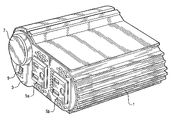
- FIG. 1 is a perspective view of the Power Inverter according to the present invention.
- FIG. 2 is a bottom side view of the Power Inverter of FIG. 1 .
- FIG. 3 is a front side view of the Power Inverter of FIG. 1 .
- FIG. 4 is a back side view of the Power Inverter of FIG. 1 .
- FIG. 5 is a left side view of the Power Inverter of FIG. 1 .
- FIG. 6 is a right side view of the Power Inverter of FIG. 1 .
- FIG. 7 is a top side view of the Power Inverter according to the present invention.
- FIG. 8 a is an exploded view of the power inverter according to the present invention.
- FIG. 8 b is an isolated view showing a rear side portion of the printed circuit board.
- FIG. 9 is a front view of the Power Inverter according to an alternate embodiment.
- FIG. 10 is a top perspective view of the Power Inverter of FIG. 9 .
- FIG. 11 is a top side view of the Power Inverter of FIG. 9 .
- FIG. 12 is a bottom view of the Power Inverter of FIG. 9 .
- FIG. 13A is a top view of the printed circuit board of the Power Inverter of FIG. 9 .
- FIG. 13B is a schematic representing the circuitry of the power inverter of FIG. 9 .
- FIG. 1 depicts a perspective view of the power inverter according to the present invention.
- FIGS. 2-7 depict the six side views of the inverter of FIG. 1 .
- a housing 11 made of aluminum or other suitable hard material encloses much of the working components of the inverter 1 with a pair of end plates 3 , 13 form to enclose the housing.
- the housing 11 has a substantially flat bottom portion in order that the inverter 1 may rest on a surface, a flat top portion opposite the flat bottom portion, and a pair of opposite side walls 12 , 13 , whereby at least wall is formed with parallel grooves 12 a extending a length of the housing.
- the parallel grooves being disposed adjacent to parallel ridges 12 b disposed next to the grooves side along an entire height ‘h’ of the housing to thereby define a side wall with a grooved configuration.
- the embodiment of FIG. 1 has horizontal ridges/grooves, while the embodiment of FIG. 9-12 has vertical ridges/grooves 112 a , 112 b .
- these ridges and grooves may help to dissipate heat generated by the inverter 1 .
- the end plate 3 has multiple outlets; two A.C. outlets 5 a , 5 b , a D.C. outlet 7 and a power switch 9 .
- the D.C. outlet represents a pass-through outlet to maintain an available D.C. power source and will be discussed in further detail below.
- FIG. 8 a depicts an exploded view of the inverter of FIG. 1 exposing the essential working components.
- power inverters for converting a 12 volt power source to an available 110 volt A.C. source is old and well known in the art.
- these components are mounted on a printed circuit board such as shown in FIG. 8 a .
- the printed circuit board has the essential components to convert a 12-volt power source for running an A.C. current consuming device.
- Such off the shelf circuitry is readily available to one of ordinary skill in the art. Thus no further details regarding the component circuitry or details regarding power inverting in general need to be discussed in further detail. Any power inverting circuitry for inverting 12 volts to A.C.
- the inverter circuitry can be designed for various power ratings over a range of watts. For example, a small 100 watt power inverter may be desirable for extreme portability to power low power consuming A.C. devices such as a clock or radio. The wattage rating may be increased to exceed 1000 watts depending on the intended application for the inverter. Such arrangements are well known in the art and are readily available.
- the present invention is primarily directed to the arrangement of power inverter components employing a pass through device to maintain the availability of the 12-volt source which powers the inverter. Thus the remaining discussion will be directed to such an arrangement.
- the present invention includes two A.C. outlets 5 a , 5 b mounted on the end plate 3 .
- the outlets 5 a , 5 b are intended to power two different A.C. consuming devices by inverting a 12 volt (or other low voltage D.C. source) to A.C.
- a D.C. voltage source is often found in automobiles.
- the present invention includes a male plug type cigarette electrical connector 17 for insertion into a female cigarette outlet commonly found in automobiles as well as other 12-volt power sources.
- Power leads (positive and ground) 19 extend from the male plug 17 through a rear end plate 21 to connect the D.C. voltage source to the printed circuit board 15 .
- the power leads may first pass through a fuse box 23 prior to connecting to printed circuit board 15 as is conventionally known in the art.
- the power leads 19 include a positive lead 19 a and ground lead 19 b which are connected/soldered to corresponding points on the printed circuit board 15 .
- the leads 19 a , 19 b are connected via removable connectors 25 a , 25 b which extend through the printed circuit board and are soldered to corresponding positive lines 27 / 28 at two points 27 a , 27 b and 28 a , 28 b to ensure a secure connection to the circuit board.
- the leads 19 bring power from an external D.C. voltage source to the inverter circuitry.
- the A.C. outlets 5 a , 5 b are connected to corresponding points on the printed circuit board as is conventional in the art and generally depicted in FIG. 8 a . As the connection and supply of A.C. current to A.C. outlets in an inverter is well within the knowledge of one of ordinary skill in the art, no further elaboration is necessary.
- the inverter of the present invention includes a pass through device to maintain the availability of a D.C. outlet while the inverter is connected to the external D.C. power source.
- the present invention includes a female cigarette plug type outlet 7 disposed on end plate 3 adjacent A.C. outlets 5 a , 5 b .
- the D.C. outlet 7 is comprised of a common female receptacle as commonly employed as cigarette lighters in vehicles.
- the female outlet 7 is correspondingly dimensioned to accommodate the male plug 17 connecter and thus mirrors the female socket of the external D.C. voltage source to which the male plug 17 is normally connected.
- a positive lead 39 a is connected through the printed circuit board and connected to positive line 27 at point 27 c as shown in FIGS. 8A & 8B .
- ground line 39 b extends from the female outlet 7 through the printed circuit board 15 and is connected to ground line 28 at point 28 c.
- the female outlet 7 draws current directly from external D.C. power source in parallel to the inverter circuitry.
- Such an arrangement facilitates simultaneous use of the A.C. outlets and the D.C. outlet to the extent the load is not excessive relative to the rating of the external D.C. voltage source to which the inverter is connected. Should the load exceed a predetermined value, the fuse 23 would open the circuit isolating the inverter circuitry and female D.C. outlet 7 from the power source.
- the present invention provides a compact portable arrangement for inverting a D.C. voltage source to power an A.C. consuming device and incorporate a pass through device to simultaneously maintain the availability of a D.C. power source.
- the inverter unit effectively provides outlets to run both A.C. power consuming devices as well as D.C. power consuming devices simultaneously without having to make or break any connection between the inverter and original external D.C. power source.
- each end plate are provided with ventilation holes to allow air to pass through the housing 11 and cool the electrical components during use.
- a fan 51 may also be employed to positively force air through the housing and may be connected to the inverter assembly as is commonly known in the art.
- FIGS. 9-13 represent an alternate embodiment of the present invention.
- the power invert of FIG. 9 is nearly identical to the power inverter shown and described in FIGS. 1-8 including all of its functional features.
- the power inverter includes internal circuitry to convert DC 12 volt source to alternative current (AC) and provides two AC outlets 105 a 105 b as well as a DC Power Source pass through device 107 just as in the previous embodiment.
- a fan 151 is also included disposed adjacent the bottom side of the device 111 as well as ventilation holes 131 to facilitate circulation of cooling air to enhance heat dissipation from the device.
- the unit 111 includes a compact portable hand holdable housing 111 and includes a cigarette lighter style male connector 117 to plug into a corresponding female socket just as in the previous embodiment.
- a power switch 109 is also included, with a status indicator LED light 109 a.
- the switch 109 is selectively positioned between an on an off position to selectively control power delivered to the AC outlets.
- FIGS. 9-13 includes at least two additional features.
- the unit incorporates a map light to provide illumination adjacent the compact inverter device 111 .
- the present invention is adapted to be simply plugged into and supported by an in-vehicle-dash DC 12 socket.
- the use of the present invention in such a vehicle dash is often in low light settings such as during night time driving.
- the map light affords the ability to provide a passenger the ability to illuminate an area that does not distract a driver such as overhead cabin lighting when the inverter is disposed in the dash 12 volt outlet. Integration of a map light into the hand held inverter device provides illumination adjacent the device to facilitate making a connection between the inverter and power consuming device in low light settings.
- the light 161 includes a clear/translucent spring biased switch plate.
- the switch plate 161 is simply depressed between an on and off position. Depressing the switch 161 overrides a small spring and catches on a retaining device in a lowered position and makes contact to close the circuit to an underlining light, preferably and LED.
- the clear translucent nature of the switch plate 161 allows the light to emanate from the switch plate 161 and provide illumination adjacent the front side of the inverter 111 .
- the switch 161 is subsequently depressed, the circuit opens and the switch plate 161 returns to its upright most/off position.
- Such lights, in and of them selves are readily available in the market and well understood to those of ordinary skill in the art.
- the Power inverter housing 111 is simply molded to accommodate such a switched light 161 to facilitate easy assembly into the housing 111 .
- the electrical connection between the light/switch 161 and internal circuitry will be easily recognized to one of ordinary skill in the art and is further shown in the schematic representation of the electronic circuitry in FIG. 13B .
- the inverter of the present invention also includes an additional outlet 171 for powering additional DC devices of lower voltage.
- An additional DC outlet (in additional to the 12V DC pass through device) is also include to power lower level voltage drawing devices such as small hand held video games.
- a USP port connection 171 (such as that shown in FIG. 9 ) is included and is shown in FIG. 9 .
- This USB connection 171 provides the ability for external devices to connect to the power inverter/converter to additional supply lower voltage DC power to either run such devices or recharge batteries in these hand held devices.
- a converter is also included in the circuitry to convert 12 volts to 5 volts and to maintain the voltage between 4.75-5.25 volts.
- the power inverter/converter of the present invention includes not only a DC/AC inverter, but a 12 volt DC pass through outlet and converting circuitry to additionally provide lower voltage DC power through a USP port.
- the combination of a power inverter to provide a Source of AC power through conventional AC outlets with a pass through device to maintain the ability to connect to the 12 Volt source which powers the inverter as well as a converter to additionally provide a lower voltage source of DC power is void in the prior art.
Abstract
Description
Claims (36)
Priority Applications (5)
| Application Number | Priority Date | Filing Date | Title |
|---|---|---|---|
| US11/808,780 US7483272B2 (en) | 2003-11-14 | 2007-06-12 | Portable hand held multi-source power inverter with pass through device |
| US12/337,291 US8154872B2 (en) | 2003-11-14 | 2008-12-17 | Portable hand held multi-source power inverter with pass through device |
| US13/443,148 US8472192B2 (en) | 2003-11-14 | 2012-04-10 | Portable hand held multi-source power inverter with pass through device |
| US29/424,697 USD687378S1 (en) | 2003-11-14 | 2012-06-14 | Power inverter |
| US13/926,512 US20130286586A1 (en) | 2003-11-14 | 2013-06-25 | Portable hand held multi-source power inverter with pass through device |
Applications Claiming Priority (5)
| Application Number | Priority Date | Filing Date | Title |
|---|---|---|---|
| US29/193,755 USD495296S1 (en) | 2003-11-14 | 2003-11-14 | Power inverter |
| US10/795,217 US7272008B2 (en) | 2004-03-09 | 2004-03-09 | Portable power inverter with pass through device |
| US29/261,268 USD544439S1 (en) | 2006-06-12 | 2006-06-12 | Power inverter |
| US11/591,529 US7298627B2 (en) | 2004-03-09 | 2006-11-02 | Portable multi-source power inverter with pass through device |
| US11/808,780 US7483272B2 (en) | 2003-11-14 | 2007-06-12 | Portable hand held multi-source power inverter with pass through device |
Related Parent Applications (3)
| Application Number | Title | Priority Date | Filing Date |
|---|---|---|---|
| US29/193,755 Continuation-In-Part USD495296S1 (en) | 2003-11-14 | 2003-11-14 | Power inverter |
| US29/261,268 Continuation-In-Part USD544439S1 (en) | 2003-11-14 | 2006-06-12 | Power inverter |
| US11/591,529 Continuation US7298627B2 (en) | 2003-11-14 | 2006-11-02 | Portable multi-source power inverter with pass through device |
Related Child Applications (2)
| Application Number | Title | Priority Date | Filing Date |
|---|---|---|---|
| US11/591,529 Continuation-In-Part US7298627B2 (en) | 2003-11-14 | 2006-11-02 | Portable multi-source power inverter with pass through device |
| US12/337,291 Continuation US8154872B2 (en) | 2003-11-14 | 2008-12-17 | Portable hand held multi-source power inverter with pass through device |
Publications (2)
| Publication Number | Publication Date |
|---|---|
| US20080024009A1 US20080024009A1 (en) | 2008-01-31 |
| US7483272B2 true US7483272B2 (en) | 2009-01-27 |
Family
ID=34919760
Family Applications (6)
| Application Number | Title | Priority Date | Filing Date |
|---|---|---|---|
| US10/795,217 Expired - Fee Related US7272008B2 (en) | 2003-11-14 | 2004-03-09 | Portable power inverter with pass through device |
| US11/591,529 Expired - Fee Related US7298627B2 (en) | 2003-11-14 | 2006-11-02 | Portable multi-source power inverter with pass through device |
| US11/808,780 Expired - Fee Related US7483272B2 (en) | 2003-11-14 | 2007-06-12 | Portable hand held multi-source power inverter with pass through device |
| US12/337,291 Expired - Fee Related US8154872B2 (en) | 2003-11-14 | 2008-12-17 | Portable hand held multi-source power inverter with pass through device |
| US13/443,148 Expired - Fee Related US8472192B2 (en) | 2003-11-14 | 2012-04-10 | Portable hand held multi-source power inverter with pass through device |
| US13/926,512 Abandoned US20130286586A1 (en) | 2003-11-14 | 2013-06-25 | Portable hand held multi-source power inverter with pass through device |
Family Applications Before (2)
| Application Number | Title | Priority Date | Filing Date |
|---|---|---|---|
| US10/795,217 Expired - Fee Related US7272008B2 (en) | 2003-11-14 | 2004-03-09 | Portable power inverter with pass through device |
| US11/591,529 Expired - Fee Related US7298627B2 (en) | 2003-11-14 | 2006-11-02 | Portable multi-source power inverter with pass through device |
Family Applications After (3)
| Application Number | Title | Priority Date | Filing Date |
|---|---|---|---|
| US12/337,291 Expired - Fee Related US8154872B2 (en) | 2003-11-14 | 2008-12-17 | Portable hand held multi-source power inverter with pass through device |
| US13/443,148 Expired - Fee Related US8472192B2 (en) | 2003-11-14 | 2012-04-10 | Portable hand held multi-source power inverter with pass through device |
| US13/926,512 Abandoned US20130286586A1 (en) | 2003-11-14 | 2013-06-25 | Portable hand held multi-source power inverter with pass through device |
Country Status (2)
| Country | Link |
|---|---|
| US (6) | US7272008B2 (en) |
| CN (1) | CN1667933A (en) |
Cited By (24)
| Publication number | Priority date | Publication date | Assignee | Title |
|---|---|---|---|---|
| US20100076615A1 (en) * | 2008-09-13 | 2010-03-25 | Moixa Energy Holdings Limited | Systems, devices and methods for electricity provision, usage monitoring, analysis, and enabling improvements in efficiency |
| USD743890S1 (en) * | 2014-08-27 | 2015-11-24 | Shenzhen Longood Intelligent Electric Co., Ltd | Electronic ballast |
| USD761199S1 (en) * | 2015-01-16 | 2016-07-12 | Lei Hong | Motorcycle power station |
| USD766826S1 (en) * | 2015-08-12 | 2016-09-20 | Guangdong Bestek E-Commerce Co., Ltd. | Inverter |
| US20170049004A1 (en) * | 2015-08-10 | 2017-02-16 | Yu-Wen Tsai | Heat Dissipation Device With Charging Function |
| USD785565S1 (en) * | 2015-08-12 | 2017-05-02 | Guangdong Bestek E-Commerce Co., Ltd. | Inverter |
| USD818953S1 (en) * | 2016-09-01 | 2018-05-29 | GUANG DONG BESTEK E-commerce Co., ltd | Sine wave inverter |
| AU2017216480B2 (en) * | 2016-10-26 | 2019-02-21 | Powertech Industrial Co., Ltd. | Outlet Device |
| USD841584S1 (en) * | 2017-12-15 | 2019-02-26 | Black & Decker Inc. | Inverter |
| USD864113S1 (en) * | 2019-04-10 | 2019-10-22 | Hua Zhang | Power inverter |
| USD871333S1 (en) * | 2017-10-02 | 2019-12-31 | Shenzhen Segre Electronic Co., Ltd. | Power converter |
| USD872020S1 (en) * | 2018-01-04 | 2020-01-07 | Xuming Chen | Inverter |
| US10555442B2 (en) * | 2016-06-01 | 2020-02-04 | Mitsubishi Electric Corporation | Power conversion device |
| USD890699S1 (en) * | 2017-11-09 | 2020-07-21 | Zhihong FENG | Inverter for vehicles |
| USD910555S1 (en) * | 2019-11-13 | 2021-02-16 | Vector Products, Inc. | Inverter |
| USD913921S1 (en) * | 2020-02-13 | 2021-03-23 | Vector Products, Inc. | Power inverter |
| USD914598S1 (en) * | 2020-01-19 | 2021-03-30 | Ningbo Zhongxin Electronic Technology Co., Ltd. | Inverter |
| USD932430S1 (en) * | 2019-11-25 | 2021-10-05 | Globe (Jiangsu) Co., Ltd | Inverter |
| USD936591S1 (en) * | 2021-02-25 | 2021-11-23 | Dejun Zhang | Inverter |
| USD953267S1 (en) * | 2021-07-09 | 2022-05-31 | Xiaoen Shi | Car inverter power supply |
| USD965522S1 (en) * | 2022-03-18 | 2022-10-04 | Yang Li | Inverter |
| USD1008961S1 (en) * | 2023-07-03 | 2023-12-26 | Guangzhou Luggex Technology Co. Ltd | Power inverter |
| USD1017544S1 (en) * | 2022-02-28 | 2024-03-12 | Signify Holding B.V. | Remote power enclosure |
| USD1019560S1 (en) * | 2023-11-22 | 2024-03-26 | Kai Chen | Power inverter |
Families Citing this family (45)
| Publication number | Priority date | Publication date | Assignee | Title |
|---|---|---|---|---|
| US7272008B2 (en) * | 2004-03-09 | 2007-09-18 | Intec, Inc. | Portable power inverter with pass through device |
| US7400859B2 (en) * | 2004-12-16 | 2008-07-15 | Intellectual Solutions, Inc. | Combined modulator and MP3 player having socket power supply adapter and/or universal connector |
| WO2006107758A2 (en) * | 2005-04-01 | 2006-10-12 | Michael Krieger | A cigarette lighter adapter device that interfaces with an external device via a port interface |
| US7463485B1 (en) * | 2005-10-28 | 2008-12-09 | Yamaichi Electronics U.S.A., Inc. | Circuit board housing and circuit board assembly |
| US20070217242A1 (en) * | 2006-03-03 | 2007-09-20 | Dayan Mervin A | Combined modulator and inverter |
| US20070253162A1 (en) * | 2006-05-01 | 2007-11-01 | Herschel Naghi | Cooling system for a consumer electronics device |
| US20070253163A1 (en) * | 2006-05-01 | 2007-11-01 | Herschel Naghi | Cooling system for a consumer electronics device |
| ITRE20070023A1 (en) * | 2007-02-23 | 2008-08-24 | Ip Cleaning S P A | '' PROFESSIONAL CLEANING MACHINE WITH INTEGRATED POWER SUPPLY FOR ACCESSORIES '' |
| DE202007011801U1 (en) | 2007-08-23 | 2009-01-02 | Dometic Waeco International Gmbh | Power supply device for the leisure and automotive sector |
| CN201178198Y (en) * | 2008-02-01 | 2009-01-07 | 富士康(昆山)电脑接插件有限公司 | Electric connector assembly |
| US7813131B2 (en) * | 2008-04-17 | 2010-10-12 | Aeon Lighting Technology Inc. | Modular outdoor LED power supply |
| US7618292B1 (en) * | 2008-08-11 | 2009-11-17 | Cheng Uei Precision Industry Co., Ltd. | Audio plug adapter and method for manufacturing the same |
| DE202009006709U1 (en) * | 2009-05-08 | 2009-08-27 | Sma Solar Technology Ag | Inverter with a housing with three chambers |
| US8922049B2 (en) | 2010-12-02 | 2014-12-30 | Hydrive Vehicles, Incorporated | System for extracting electrical power from an electric vehicle |
| US9755435B2 (en) | 2011-08-16 | 2017-09-05 | Philips Lighting Holding B.V. | Wireless power converter utilized as a capacitive power transfer system |
| DE102012205972A1 (en) | 2012-04-12 | 2013-10-17 | Bayerische Motoren Werke Aktiengesellschaft | charging system |
| US11228187B2 (en) | 2013-05-04 | 2022-01-18 | Paul Andrew Romanenko | Caddy charger |
| WO2016004379A2 (en) * | 2014-07-02 | 2016-01-07 | Sst-Technologies Llc | Collapsible solar refrigerator device |
| US20150028668A1 (en) * | 2013-07-25 | 2015-01-29 | WWL Vehicle Services Americas, Inc. | Modular Vehicle Unit |
| TWI535134B (en) | 2014-01-02 | 2016-05-21 | 萬國商業機器公司 | Apparatus for power interconnection and receptacle structure and method of providing a direct current |
| WO2015187500A1 (en) * | 2014-06-02 | 2015-12-10 | Enphase Energy, Inc. | Ungrounded inverter enclosure and cabling |
| US9701264B2 (en) * | 2014-06-20 | 2017-07-11 | Andrew Aboudaoud | Systems and methods for coupling a power converter to a fuse tap |
| USD792846S1 (en) * | 2015-01-13 | 2017-07-25 | Sun Pleasure Co., Ltd. | Portable energy storage and distribution device |
| US9298228B1 (en) * | 2015-02-12 | 2016-03-29 | Rambus Inc. | Memory capacity expansion using a memory riser |
| CA2977518A1 (en) * | 2015-02-24 | 2016-09-01 | Das Companies, Inc. | Remote power control and monitoring of a vehicle power system |
| JP6020750B1 (en) * | 2015-02-27 | 2016-11-02 | 三菱マテリアル株式会社 | Transparent conductive wiring and method for manufacturing transparent conductive wiring |
| USD810018S1 (en) * | 2015-04-24 | 2018-02-13 | Das Companies, Inc. | Power inverter |
| CN204696941U (en) * | 2015-06-29 | 2015-10-07 | 广州庭升电器有限公司 | The transformer frequency response that a kind of tool AC and DC exports and lamp string |
| ITUB20159345A1 (en) * | 2015-12-23 | 2017-06-23 | Comau Spa | Multi-axis industrial robot, in particular of the SCARA type |
| TWM522495U (en) * | 2016-01-28 | 2016-05-21 | 展達通訊股份有限公司 | Electronic apparatus |
| USD805473S1 (en) * | 2016-05-05 | 2017-12-19 | Nicholas Montgomery | Power inverter |
| USD929325S1 (en) | 2016-05-05 | 2021-08-31 | Nicholas Montgomery | Power inverter |
| TWI656428B (en) * | 2017-03-08 | 2019-04-11 | 仁寶電腦工業股份有限公司 | Cover and electronic device having the same |
| USD825459S1 (en) * | 2017-05-02 | 2018-08-14 | Shenzhen Segre Electronic Co., Ltd | Inverter |
| US10177515B2 (en) | 2017-05-17 | 2019-01-08 | Eaton Intelligent Power Limited | Lug assemblies and related electrical apparatus and methods |
| US10165638B1 (en) * | 2017-06-09 | 2018-12-25 | Guang Zhou Ting Shen Electric Co., Ltd. | Controller structure for LED light strings |
| USD828297S1 (en) * | 2017-09-29 | 2018-09-11 | Shenzhen Valuelink E-Commerce Co., Ltd. | Inverter |
| USD828296S1 (en) * | 2017-09-29 | 2018-09-11 | Shenzhen Valuelink E-Commerce Co., Ltd. | Inverter |
| USD853328S1 (en) * | 2017-10-18 | 2019-07-09 | Shenzhen Segre Electronics Co.,Ltd | Car inverter |
| CN108173076A (en) * | 2017-12-20 | 2018-06-15 | 西安中车永电电气有限公司 | A kind of train quick high-pressure electrical connection arrangement |
| JP6687061B2 (en) * | 2018-07-02 | 2020-04-22 | カシオ計算機株式会社 | Information communication device, information communication system, and program |
| USD910573S1 (en) | 2018-11-06 | 2021-02-16 | Halo International SEZC Ltd. | Portable power strip |
| US11431191B2 (en) | 2019-07-24 | 2022-08-30 | Constellation Energy Generation, Llc | Methods and systems for providing power |
| CN111464048B (en) * | 2020-06-08 | 2021-07-02 | 安徽民生信息股份有限公司 | Portable inversion integrated device |
| US20220112908A1 (en) * | 2020-10-13 | 2022-04-14 | Exelon Generation Company, Llc | Systems and apparatuses for portable air distribution |
Citations (22)
| Publication number | Priority date | Publication date | Assignee | Title |
|---|---|---|---|---|
| JPH0393921A (en) | 1989-09-06 | 1991-04-18 | Shimizu Corp | Cut-off wall construction method |
| US5170067A (en) | 1990-11-27 | 1992-12-08 | Unitech Industries, Inc. | Plug insertable into a vehicle cigarette lighter receptacle and having electronic components and a printed circuit board therein |
| USD343395S (en) | 1991-02-06 | 1994-01-18 | Sony Corporation | Amplifier for car |
| USD349682S (en) | 1993-04-08 | 1994-08-16 | Melcher Ag | Power converter casing |
| US5742478A (en) * | 1996-09-25 | 1998-04-21 | Wu; Chih-Hsien | Radiating structure of a power converter |
| USD409139S (en) | 1998-10-15 | 1999-05-04 | Progressive Dynamics, Inc. | Converter/charger |
| US5949640A (en) * | 1997-08-19 | 1999-09-07 | Statpower Technologies Corp. | Power inverter with re-orientable display panel and AC port modules |
| USD427146S (en) | 1999-06-07 | 2000-06-27 | Cheng Tsung Wei | Power inverter |
| USD427147S (en) | 1999-06-07 | 2000-06-27 | Cheng Tsung Wei | Power inverter |
| USD436918S1 (en) | 2000-01-04 | 2001-01-30 | Hari Matsuda | Voltage inverter |
| US6433274B1 (en) * | 2000-01-06 | 2002-08-13 | Mobility Electronic, Inc. | Power converter device |
| USD465781S1 (en) | 2001-05-22 | 2002-11-19 | Safco Corporation | Hands free accessory for wireless telephones |
| USD469400S1 (en) | 2002-01-28 | 2003-01-28 | Otniel Shor | Vehicle charger adapter |
| USD480054S1 (en) | 2002-03-20 | 2003-09-30 | Safco Corporation | Automotive electronics enclosure with a single outlet |
| US20030205596A1 (en) | 2002-05-06 | 2003-11-06 | Ling Tse Sau | Robotic arm console |
| USD482654S1 (en) | 2002-09-27 | 2003-11-25 | Otniel Shor | Charger adapter |
| USD494542S1 (en) | 2003-12-01 | 2004-08-17 | Xantrex International | Plug-type power inverter |
| USD495296S1 (en) | 2003-11-14 | 2004-08-31 | Intec, Inc. | Power inverter |
| US7046535B2 (en) * | 2003-12-17 | 2006-05-16 | Ballard Power Systems Corporation | Architecture for power modules such as power inverters |
| USD544439S1 (en) | 2006-06-12 | 2007-06-12 | I-Tec Electronics Inc. | Power inverter |
| US7298627B2 (en) * | 2004-03-09 | 2007-11-20 | Intec, Inc. | Portable multi-source power inverter with pass through device |
| US7338328B2 (en) | 2005-04-01 | 2008-03-04 | The Black & Decker Corporation | Cigarette lighter adapter device that interfaces with an external device via a port interface |
Family Cites Families (25)
| Publication number | Priority date | Publication date | Assignee | Title |
|---|---|---|---|---|
| US4872102A (en) * | 1986-04-28 | 1989-10-03 | Dimensions Unlimited, Inc. | D.C. to A.C. inverter having improved structure providing improved thermal dissipation |
| JPH0393921U (en) | 1990-01-17 | 1991-09-25 | ||
| US5170336A (en) * | 1990-03-05 | 1992-12-08 | Dimensions Unlimited, Inc. | DC to AC inverter with improved forced air cooling method and apparatus |
| US5077652A (en) * | 1990-10-18 | 1991-12-31 | Dynamote Corporation | Dual feedback loop DC-to-AC converter |
| US5321596A (en) * | 1991-03-25 | 1994-06-14 | Raynet Corporation | DC/DC/AC power supply for a subscriber interphase unit |
| US5355300A (en) * | 1993-07-06 | 1994-10-11 | Zinn James K | Voltage converter |
| US5687066A (en) * | 1995-04-06 | 1997-11-11 | Progressive Dynamics, Inc. | Power converter with overvoltage protection |
| US5684689A (en) * | 1996-06-19 | 1997-11-04 | Advanced Mobile Solutions, Inc. | Interchangeable plug power supply with automatically adjusting input voltage receiving mechanism |
| US5829993A (en) * | 1996-12-16 | 1998-11-03 | Formosa Electronic Industries Inc. | Charger with a replaceable electrical plug |
| TW328403U (en) * | 1997-05-09 | 1998-03-11 | Formosa Electronicindustries Inc | Ac/dc power supplier having a replaceable plug |
| US5901056A (en) * | 1997-12-03 | 1999-05-04 | Hung; Sheng-Chuan | DC power supply device adapted to operate with an AC power supply or with a car battery via a cigarette lighter |
| US6434032B1 (en) * | 1998-09-03 | 2002-08-13 | Philip D. Anderson | Power supply with plug-receiving receptacles carried on bracket affixed to battery casing |
| US5982138A (en) * | 1998-12-17 | 1999-11-09 | Vector Manufacturing, Ltd. | Portable electrical energy source |
| US6111772A (en) * | 1999-06-29 | 2000-08-29 | Lee; Chiu-Shan | Universal, voltage variable, safety enhanced electric connector |
| US6577098B2 (en) * | 2000-05-17 | 2003-06-10 | Delphi Technologies, Inc. | Apparatus and method for providing a mobile AC power supply |
| US6411514B1 (en) * | 2001-03-08 | 2002-06-25 | Rally Manufacturing, Inc. | Power inverter with heat dissipating assembly |
| USD455712S1 (en) | 2001-04-18 | 2002-04-16 | Len Cheng Brother Co., Ltd. | Joint connector for automobile battery charging cord |
| US20020171391A1 (en) * | 2001-05-17 | 2002-11-21 | Carolyn Batts-Gowins | Portable AC power supply with multiple uses |
| TW543994U (en) * | 2001-12-25 | 2003-07-21 | Sheng-Shing Liau | Easy carrying multi-function charger |
| US6747246B2 (en) * | 2002-03-04 | 2004-06-08 | Crandell, Iii John O. | Integrated mobile tool and welder power supply system |
| US6628535B1 (en) * | 2002-03-20 | 2003-09-30 | Formosa Electronic Industries Inc. | Voltage converter with selectable DC output voltage level |
| US6842356B2 (en) * | 2002-06-21 | 2005-01-11 | Benjamin Hsu | Firewire/USB bus-charger for 12V DC automotive |
| US6621724B1 (en) * | 2002-06-28 | 2003-09-16 | Pacific Carnetta, Inc. | Electrical power strip and plug for vehicle accessory |
| US7011538B2 (en) * | 2004-06-02 | 2006-03-14 | Elementech International Co., Ltd. | Dual input charger with cable storing mechanism |
| US7565968B2 (en) * | 2006-03-13 | 2009-07-28 | Lindley Michael B | Portable survival kit |
-
2004
- 2004-03-09 US US10/795,217 patent/US7272008B2/en not_active Expired - Fee Related
- 2004-07-29 CN CNA2004100590433A patent/CN1667933A/en active Pending
-
2006
- 2006-11-02 US US11/591,529 patent/US7298627B2/en not_active Expired - Fee Related
-
2007
- 2007-06-12 US US11/808,780 patent/US7483272B2/en not_active Expired - Fee Related
-
2008
- 2008-12-17 US US12/337,291 patent/US8154872B2/en not_active Expired - Fee Related
-
2012
- 2012-04-10 US US13/443,148 patent/US8472192B2/en not_active Expired - Fee Related
-
2013
- 2013-06-25 US US13/926,512 patent/US20130286586A1/en not_active Abandoned
Patent Citations (23)
| Publication number | Priority date | Publication date | Assignee | Title |
|---|---|---|---|---|
| JPH0393921A (en) | 1989-09-06 | 1991-04-18 | Shimizu Corp | Cut-off wall construction method |
| US5170067A (en) | 1990-11-27 | 1992-12-08 | Unitech Industries, Inc. | Plug insertable into a vehicle cigarette lighter receptacle and having electronic components and a printed circuit board therein |
| USD343395S (en) | 1991-02-06 | 1994-01-18 | Sony Corporation | Amplifier for car |
| USD349682S (en) | 1993-04-08 | 1994-08-16 | Melcher Ag | Power converter casing |
| US5742478A (en) * | 1996-09-25 | 1998-04-21 | Wu; Chih-Hsien | Radiating structure of a power converter |
| US5949640A (en) * | 1997-08-19 | 1999-09-07 | Statpower Technologies Corp. | Power inverter with re-orientable display panel and AC port modules |
| USD409139S (en) | 1998-10-15 | 1999-05-04 | Progressive Dynamics, Inc. | Converter/charger |
| USD427146S (en) | 1999-06-07 | 2000-06-27 | Cheng Tsung Wei | Power inverter |
| USD427147S (en) | 1999-06-07 | 2000-06-27 | Cheng Tsung Wei | Power inverter |
| USD427969S (en) | 1999-06-07 | 2000-07-11 | Cheng Tsung Wei | Power inverter |
| USD436918S1 (en) | 2000-01-04 | 2001-01-30 | Hari Matsuda | Voltage inverter |
| US6433274B1 (en) * | 2000-01-06 | 2002-08-13 | Mobility Electronic, Inc. | Power converter device |
| USD465781S1 (en) | 2001-05-22 | 2002-11-19 | Safco Corporation | Hands free accessory for wireless telephones |
| USD469400S1 (en) | 2002-01-28 | 2003-01-28 | Otniel Shor | Vehicle charger adapter |
| USD480054S1 (en) | 2002-03-20 | 2003-09-30 | Safco Corporation | Automotive electronics enclosure with a single outlet |
| US20030205596A1 (en) | 2002-05-06 | 2003-11-06 | Ling Tse Sau | Robotic arm console |
| USD482654S1 (en) | 2002-09-27 | 2003-11-25 | Otniel Shor | Charger adapter |
| USD495296S1 (en) | 2003-11-14 | 2004-08-31 | Intec, Inc. | Power inverter |
| USD494542S1 (en) | 2003-12-01 | 2004-08-17 | Xantrex International | Plug-type power inverter |
| US7046535B2 (en) * | 2003-12-17 | 2006-05-16 | Ballard Power Systems Corporation | Architecture for power modules such as power inverters |
| US7298627B2 (en) * | 2004-03-09 | 2007-11-20 | Intec, Inc. | Portable multi-source power inverter with pass through device |
| US7338328B2 (en) | 2005-04-01 | 2008-03-04 | The Black & Decker Corporation | Cigarette lighter adapter device that interfaces with an external device via a port interface |
| USD544439S1 (en) | 2006-06-12 | 2007-06-12 | I-Tec Electronics Inc. | Power inverter |
Cited By (27)
| Publication number | Priority date | Publication date | Assignee | Title |
|---|---|---|---|---|
| US11437822B2 (en) | 2008-09-13 | 2022-09-06 | Moixa Energy Holdings Limited | Systems, devices and methods for electricity provision, usage monitoring, analysis, and enabling improvements in efficiency |
| US8849471B2 (en) * | 2008-09-13 | 2014-09-30 | Moixa Energy Holdings Limited | Systems, devices and methods for electricity provision, usage monitoring, analysis, and enabling improvements in efficiency |
| US20100076615A1 (en) * | 2008-09-13 | 2010-03-25 | Moixa Energy Holdings Limited | Systems, devices and methods for electricity provision, usage monitoring, analysis, and enabling improvements in efficiency |
| US11418040B2 (en) | 2008-09-13 | 2022-08-16 | Moixa Energy Holdings Limited | Aggregating and managing recharging of portable/EV batteries via sockets |
| USD743890S1 (en) * | 2014-08-27 | 2015-11-24 | Shenzhen Longood Intelligent Electric Co., Ltd | Electronic ballast |
| USD761199S1 (en) * | 2015-01-16 | 2016-07-12 | Lei Hong | Motorcycle power station |
| US20170049004A1 (en) * | 2015-08-10 | 2017-02-16 | Yu-Wen Tsai | Heat Dissipation Device With Charging Function |
| USD785565S1 (en) * | 2015-08-12 | 2017-05-02 | Guangdong Bestek E-Commerce Co., Ltd. | Inverter |
| USD766826S1 (en) * | 2015-08-12 | 2016-09-20 | Guangdong Bestek E-Commerce Co., Ltd. | Inverter |
| US10555442B2 (en) * | 2016-06-01 | 2020-02-04 | Mitsubishi Electric Corporation | Power conversion device |
| USD818953S1 (en) * | 2016-09-01 | 2018-05-29 | GUANG DONG BESTEK E-commerce Co., ltd | Sine wave inverter |
| AU2017216480B2 (en) * | 2016-10-26 | 2019-02-21 | Powertech Industrial Co., Ltd. | Outlet Device |
| USD871333S1 (en) * | 2017-10-02 | 2019-12-31 | Shenzhen Segre Electronic Co., Ltd. | Power converter |
| USD890699S1 (en) * | 2017-11-09 | 2020-07-21 | Zhihong FENG | Inverter for vehicles |
| USD841584S1 (en) * | 2017-12-15 | 2019-02-26 | Black & Decker Inc. | Inverter |
| USD872020S1 (en) * | 2018-01-04 | 2020-01-07 | Xuming Chen | Inverter |
| USD864113S1 (en) * | 2019-04-10 | 2019-10-22 | Hua Zhang | Power inverter |
| USD910555S1 (en) * | 2019-11-13 | 2021-02-16 | Vector Products, Inc. | Inverter |
| USD932430S1 (en) * | 2019-11-25 | 2021-10-05 | Globe (Jiangsu) Co., Ltd | Inverter |
| USD914598S1 (en) * | 2020-01-19 | 2021-03-30 | Ningbo Zhongxin Electronic Technology Co., Ltd. | Inverter |
| USD913921S1 (en) * | 2020-02-13 | 2021-03-23 | Vector Products, Inc. | Power inverter |
| USD936591S1 (en) * | 2021-02-25 | 2021-11-23 | Dejun Zhang | Inverter |
| USD953267S1 (en) * | 2021-07-09 | 2022-05-31 | Xiaoen Shi | Car inverter power supply |
| USD1017544S1 (en) * | 2022-02-28 | 2024-03-12 | Signify Holding B.V. | Remote power enclosure |
| USD965522S1 (en) * | 2022-03-18 | 2022-10-04 | Yang Li | Inverter |
| USD1008961S1 (en) * | 2023-07-03 | 2023-12-26 | Guangzhou Luggex Technology Co. Ltd | Power inverter |
| USD1019560S1 (en) * | 2023-11-22 | 2024-03-26 | Kai Chen | Power inverter |
Also Published As
| Publication number | Publication date |
|---|---|
| US8472192B2 (en) | 2013-06-25 |
| US8154872B2 (en) | 2012-04-10 |
| US7272008B2 (en) | 2007-09-18 |
| US20120195088A1 (en) | 2012-08-02 |
| US20130286586A1 (en) | 2013-10-31 |
| CN1667933A (en) | 2005-09-14 |
| US20080024009A1 (en) | 2008-01-31 |
| US20090161317A1 (en) | 2009-06-25 |
| US7298627B2 (en) | 2007-11-20 |
| US20050200206A1 (en) | 2005-09-15 |
| US20070091575A1 (en) | 2007-04-26 |
Similar Documents
| Publication | Publication Date | Title |
|---|---|---|
| US7483272B2 (en) | Portable hand held multi-source power inverter with pass through device | |
| US6874907B2 (en) | USB-chargeable emergency light structure | |
| US6149288A (en) | Vehicle light assembly with detachable and replaceable circuit board having plug-in terminal connectors | |
| US4924246A (en) | Energizing system for video cameras and lights using adapter modules | |
| US6527409B1 (en) | Apparatus for illuminating a portable electronic device and method for using the same | |
| US8105106B1 (en) | Disposable illuminated electrical plug adapter | |
| US20070133219A1 (en) | Vehicle interior light assembly with removable flashlight | |
| EP0795437A2 (en) | Structure of vehicle glove box | |
| US9461488B2 (en) | Battery with integrated power inverter | |
| US20060176687A1 (en) | Vehicle charger/flashlight | |
| US7158382B2 (en) | Uninterruptible power supply socket | |
| JP6868818B2 (en) | Tabletop | |
| US6053765A (en) | Electrical connector incorporating a light | |
| JP3228645U (en) | Vehicle charging socket | |
| JP3677773B2 (en) | Lighting device | |
| CN217589657U (en) | Embedded socket and have its home equipment | |
| CN215851062U (en) | Vehicle-mounted multifunctional control unit | |
| US20210006021A1 (en) | Conductive building block having different heights | |
| JPH0216477Y2 (en) | ||
| GB2388968A (en) | Fused power adaptor | |
| JP2021044255A (en) | Table tap | |
| JP2001095264A (en) | On-vehicle dc/ac converter | |
| KR200203679Y1 (en) | Seperatable charger for cordless telephone | |
| KR970008756A (en) | Automotive Electric Distribution System | |
| GB2393047A (en) | Solar powered battery charger |
Legal Events
| Date | Code | Title | Description |
|---|---|---|---|
| AS | Assignment |
Owner name: INTEC, INC., FLORIDA Free format text: ASSIGNMENT OF ASSIGNORS INTEREST;ASSIGNORS:HUSSAINI, SAIED;IACOVELLI, MARC;REEL/FRAME:019947/0917 Effective date: 20071003 |
|
| FPAY | Fee payment |
Year of fee payment: 4 |
|
| AS | Assignment |
Owner name: COMPUTER PATENT SYSTEMS, LLC, VIRGINIA Free format text: ASSIGNMENT OF ASSIGNORS INTEREST;ASSIGNOR:INTEC, INC.;REEL/FRAME:030933/0948 Effective date: 20130320 |
|
| AS | Assignment |
Owner name: MOBILE CHARGING SOLUTIONS INC., CALIFORNIA Free format text: ASSIGNMENT OF ASSIGNORS INTEREST;ASSIGNOR:COMPUTER PATENT SYSTEMS LLC;REEL/FRAME:034817/0020 Effective date: 20150112 |
|
| REMI | Maintenance fee reminder mailed | ||
| LAPS | Lapse for failure to pay maintenance fees | ||
| STCH | Information on status: patent discontinuation |
Free format text: PATENT EXPIRED DUE TO NONPAYMENT OF MAINTENANCE FEES UNDER 37 CFR 1.362 |
|
| FP | Lapsed due to failure to pay maintenance fee |
Effective date: 20170127 |