US6511182B1 - Autostereoscopic optical apparatus using a scanned linear image source - Google Patents
Autostereoscopic optical apparatus using a scanned linear image source Download PDFInfo
- Publication number
- US6511182B1 US6511182B1 US10/010,500 US1050001A US6511182B1 US 6511182 B1 US6511182 B1 US 6511182B1 US 1050001 A US1050001 A US 1050001A US 6511182 B1 US6511182 B1 US 6511182B1
- Authority
- US
- United States
- Prior art keywords
- image
- optical apparatus
- ball lens
- autostereoscopic optical
- source
- Prior art date
- Legal status (The legal status is an assumption and is not a legal conclusion. Google has not performed a legal analysis and makes no representation as to the accuracy of the status listed.)
- Expired - Lifetime
Links
Images


Classifications
-
- H—ELECTRICITY
- H04—ELECTRIC COMMUNICATION TECHNIQUE
- H04N—PICTORIAL COMMUNICATION, e.g. TELEVISION
- H04N13/00—Stereoscopic video systems; Multi-view video systems; Details thereof
-
- G—PHYSICS
- G02—OPTICS
- G02B—OPTICAL ELEMENTS, SYSTEMS OR APPARATUS
- G02B30/00—Optical systems or apparatus for producing three-dimensional [3D] effects, e.g. stereoscopic images
- G02B30/20—Optical systems or apparatus for producing three-dimensional [3D] effects, e.g. stereoscopic images by providing first and second parallax images to an observer's left and right eyes
- G02B30/26—Optical systems or apparatus for producing three-dimensional [3D] effects, e.g. stereoscopic images by providing first and second parallax images to an observer's left and right eyes of the autostereoscopic type
- G02B30/33—Optical systems or apparatus for producing three-dimensional [3D] effects, e.g. stereoscopic images by providing first and second parallax images to an observer's left and right eyes of the autostereoscopic type involving directional light or back-light sources
Definitions
- This invention generally relates to autostereoscopic display systems for viewing electronically generated images and more particularly relates to an apparatus and method for generating left- and right-eye images using a scanned linear image source with a monocentric arrangement of optical components to provide a very wide field of view and large exit pupils.
- Autostereoscopic display systems include “immersion” systems, intended to provide a realistic viewing experience for an observer by visually surrounding the observer with a 3-D image having a very wide field of view.
- the autostereoscopic display is characterized by the absence of any requirement for a wearable item of any type, such as, for example, goggles, headgear, or special glasses. That is, an autostereoscopic display attempts to provide “natural” viewing conditions for an observer.
- Kintz design provides one solution for a truly autostereoscopic system having a wide field of view
- this design has considerable drawbacks.
- disadvantages of the Kintz design is the requirement that the observer's head be in close proximity to a rapidly spinning surface.
- Such an approach requires measures to minimize the likelihood of accident and injury from contact with components on the spinning surface.
- proximity to a rapidly moving surface could, at the least, cause the observer some apprehension.
- use of such a system imposes considerable constraints on head movement.
- One class of autostereoscopic systems that operates by imaging the exit pupils of a pair of projectors onto the eyes of an observer is as outlined in an article by S. A. Benton, T. E. Slowe, A. B. Kropp, and S. L. Smith (“Micropolarizer-based multiple-viewer autostereoscopic display,” in Stereoscopic Displays and Virtual Reality Systems VI, SPIE, January, 1999).
- Pupil imaging as outlined by Benton in the above-mentioned article, can be implemented using large lenses or mirrors.
- An observer whose eyes are coincident with the imaged pupils can view a stereoscopic scene without crosstalk, without wearing eyewear of any kind.
- an autostereoscopic display system using pupil imaging is enhanced by presenting the 3-D image with a wide field of view and large exit pupil.
- Such a system is most effective for immersive viewing functions if it allows an observer to be comfortably seated, without constraining head movement to within a tight tolerance and without requiring the observer to wear goggles or other device.
- 3-D viewing such a system should provide separate, high-resolution images to right and left eyes.
- such a system is most favorably designed for compactness, to create an illusion of depth and width of field, while occupying as little actual floor space and volume as is possible.
- the observer should be presented with a virtual image, disposed to appear a large distance away.
- Vergence refers to the degree at which the observer's eyes must be crossed in order to fuse the separate images of an object within the field of view. Vergence decreases, then vanishes as viewed objects become more distant.
- Accommodation refers to the requirement that the eye lens of the observer change shape to maintain retinal focus for the object of interest. It is known that there can be a temporary degradation of the observer's depth perception when the observer is exposed for a period of time to mismatched depth cues for vergence and accommodation. It is also known that this negative effect on depth perception can be mitigated when the accommodation cues correspond to distant image position.
- 5,908,300 discloses a hang-gliding simulation system in which an observer's head is maintained in a fixed position. While such a solution may be tolerable in the limited simulation environment disclosed in the Walker et al. patent, and may simplify the overall optical design of an apparatus, constraint of head movement would be a disadvantage in an immersion system. Notably, the system disclosed in the Walker et al. patent employs a narrow viewing aperture, effectively limiting the field of view. Complex, conventional projection lenses, disposed in an off-axis orientation, are employed in the device disclosed in U.S. Pat. No. 5,908,300, with scaling used to obtain the desired output pupil size.
- a 3-D viewing system should display its pair of stereoscopic images, whether real or virtual, at a relatively large distance from the observer.
- a large display screen must be employed, preferably placed a good distance from the observer.
- a relatively small curved mirror can be used as is disclosed in U.S. Pat. No. 5,908,300 (Walker). The curved mirror acts as a collimator, providing a virtual image at a large distance from the observer.
- Curved mirrors have also been used to provide real images in stereoscopic systems, wherein the curved mirrors are not used as collimators. Such systems are disclosed in U.S. Pat. No. 4,623,223 (Kempf); and U.S. Pat. No. 4,799,763 (Davis et al.) for example. However, systems such as these are generally suitable where only a small field of view is needed.
- a system designed for pupil imaging must provide separate images to the left and right pupils correspondingly and provide the most natural viewing conditions, eliminating any need for goggles or special headgear.
- An ideal autostereoscopic imaging system must meet the challenge for both requirements to provide a more fully satisfactory and realistic viewing experience.
- such a system must provide sufficient resolution for realistic imaging, with high brightness and contrast.
- interocular distance constraints limit the ability to achieve larger pupil diameter at a given ultrawide field by simply scaling the projection lens.
- Monocentric imaging systems have been shown to provide significant advantages for high-resolution imaging of flat objects, such as is disclosed in U.S. Pat. No. 3,748,015 (Offner), which teaches an arrangement of spherical mirrors arranged with coincident centers of curvature in an imaging system designed for unit magnification.
- the monocentric arrangement disclosed in the Offner patent minimizes a number of types of image aberration and is conceptually straightforward, allowing a simplified optical design for high-resolution catoptric imaging systems.
- a monocentric arrangement of mirrors and lenses is also known to provide advantages for telescopic systems having wide field of view, as is disclosed in U.S. Pat. No. 4,331,390 (Shafer).
- the lens For larger pupil size, the lens needs to be scaled in size; however, the large diameter of such a lens body presents a significant design difficulty for an autostereoscopic immersion system, relative to the interocular distance at the viewing position. Costly cutting of lenses so that right- and left-eye assemblies could be disposed side-by-side, thereby achieving a pair of lens pupils spaced consistently with human interocular separation, presents difficult manufacturing problems. Interocular distance limitations constrain the spatial positioning of projection apparatus for each eye and preclude scaling of pupil size by simple scaling of the lens. Moreover, an effective immersion system most advantageously allows a very wide field of view, preferably well in excess of 90 degrees, and would provide large exit pupil diameters, preferably larger than 20 mm.
- ball lenses have been employed for specialized optical functions, particularly miniaturized ball lenses for use in fiber optics coupling and transmission applications, such as is disclosed in U.S. Pat. No. 5,940,564 (Jewell) which discloses advantageous use of a miniature ball lens within a coupling device.
- ball lenses can be utilized within an astronomical tracking device, as is disclosed in U.S. Pat. No. 5,206,499 (Mantravadi et al.) In the Mantravadi et al. patent, the ball lens is employed because it allows a wide field of view, greater than 60 degrees, with minimal off-axis aberrations or distortions.
- a unique optical axis is used advantageously, so that every principal ray that passes through the ball lens can be considered to define its own optical axis.
- a single ball lens is favorably used to direct light from space to a plurality of sensors in this application.
- photosensors at the output of the ball lens are disposed along a curved focal plane.
- a spherical or ball lens for wide angle imaging are also utilized in an apparatus for determining space-craft attitude, as is disclosed in U.S. Pat. No. 5,319,968 (Billing-Ross et al.)
- an array of mirrors direct light rays through a ball lens.
- the shape of this lens is advantageous since beams which pass through the lens are at normal incidence to the image surface. The light rays are thus refracted toward the center of the lens, resulting in an imaging system having a wide field of view.
- any imaging system conforms to the Lagrange invariant, whereby the product of pupil size and semi-field angle is equal to the product of the image size and the numerical aperture and is an invariant for the optical system.
- This can be a limitation when using, as an image generator, a relatively small spatial light modulator or similar pixel array which can operate over a relatively small numerical aperture since the Lagrange value associated with the device is small.
- a monocentric imaging system provides a large field of view with a large pupil size (that is, a large numerical aperture), inherently has a large Lagrange value.
- Copending U.S. patent applications Ser. Nos. 09/738,747 and 09/854,699 take advantage of capabilities for wide field of view projection using a ball lens in an autostereoscopic imaging system.
- the source image that is provided to the projecting ball lens for each eye is presented as a complete two-dimensional image.
- the image source disclosed in each of these applications is a two-dimensional array, such as an LCD, a DMD, or similar device.
- the image source could alternately be a CRT which, even though generated by a scanned electron beam, presents a complete two-dimensional image to ball lens projection optics.
- a curved image field is preferred, with the center of curvature of this field coincident with the center of the ball lens, since this arrangement minimizes field aberrations.
- providing a curved image field requires either curving the image source itself or providing an additional faceplate or special relay optics in the imaging path. Curving a two-dimensional image array to obtain or approximate spherical curvature of the image source would be difficult and costly.
- Employing a faceplate or special relay optics with a planar image array has disadvantages including added cost and overall loss of brightness. Maintaining sufficient brightness for projection is a concern when using small two-dimensioned arrays, since this can be difficult to achieve without special design techniques and higher-cost components.
- a beamsplitter disposed to fold the optical path from the left image generation system to form the left intermediate image near a front focal surface of the curved mirror and to fold the optical path from the right image generation system to form the right intermediate image near the front focal surface of the curved mirror;
- a feature of the present invention is the use of a monocentric arrangement of optical components, thus simplifying design, minimizing aberrations and providing a wide field of view with large exit pupils.
- a further feature of the present invention is the use of a linear image source, such as a combination comprising a scanned point source and a diffusive surface or a linear array of light sources, scanned by a ball lens segment having a reflective surface in order to provide a scanned intermediate image.
- a linear image source such as a combination comprising a scanned point source and a diffusive surface or a linear array of light sources, scanned by a ball lens segment having a reflective surface in order to provide a scanned intermediate image.
- a further feature of the present invention is that it allows a number of configurations, including configurations that minimize the number of optical components required, even including configurations that eliminate the need for a beamsplitter.
- It is an advantage of the present invention is that it eliminates the need for a higher cost two-dimensional surface as image source, replacing this with a lower cost scanned point source or linear array.
- the present invention provides a system that is very light-efficient, capable of providing high brightness levels for projection.
- FIG. 1 is a perspective view showing key components of the apparatus of the present invention in an autostereoscopic imaging system
- FIGS. 2 a and 2 b are side and top schematic views, respectively, showing the substantially concentric relationship of projection optics in an optically unfolded view;
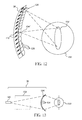
- FIG. 3 is a schematic view showing the concentric relationship of projection optics as used by the system, in an optically folded view;
- FIG. 4 is a perspective view showing, for one left or right image, the scanning action obtained from cooperation of a linear image source and scanning ball lens assembly;
- FIG. 5 is a side view representation showing the relationship of the curved linear image source and the scanning ball lens assembly
- FIG. 6 is a perspective view showing, in exaggerated detail, how successive lines of pixels are scanned to form the intermediate image
- FIGS. 7 a- 7 c are top views showing the relationship of the curved linear image source and scanning ball lens assemblies and the interaction of these components in order to create a scanned intermediate image;
- FIG. 8 is a cross-section view showing the composition of a scanning ball lens assembly
- FIG. 9 is a perspective view showing key components of the apparatus of the present invention for an alternate embodiment autostereoscopic imaging system using a curved mirror and essentially paraxial optics;
- FIG. 10 is a perspective view showing key components of the apparatus of the present invention for another alternate embodiment autostereoscopic imaging system using a Fresnel mirror and essentially paraxial optics;
- FIG. 11 is a perspective schematic view of light sources according to one embodiment of the present invention.
- FIG. 12 is a linear array of light sources and lenses according to another embodiment of the present invention.
- FIG. 13 is a schematic view of a scanning electron beam light source according to the present invention.
- FIG. 14 is a schematic view of another embodiment of the present invention using a resonant fiber optic scan for the light source.
- FIG. 15 shows a schematic view of an alternate embodiment of the scanning ball assembly using a beamsplitter surface.
- FIG. 1 there is shown a perspective view of an autostereoscopic imaging system 10 .
- An observer 12 is typically seated in position to view a virtual stereoscopic image from left and right viewing pupils 14 l and 14 r .
- Optimal viewing conditions are obtained when left and right eye pupils 68 l and 68 r of observer 12 are coincident with the position of corresponding left and right viewing pupils 14 l and 14 r.
- a left image generation system 70 l comprising a left scanning ball lens assembly 100 l and a left linear image source 36 l project the image intended for left viewing pupil 14 l .
- a right image generation system 70 r comprising a right scanning ball lens assembly 100 r and a right linear image source 36 r project the image intended for right viewing pupil 14 r .
- Left image generation system 70 l directs an image to a beamsplitter 16 which is interposed between observer 12 and a curved mirror 24 .
- a left intermediate image 76 l is formed near a focal surface 22 of curved mirror 24 .
- Left intermediate image 76 l is presented at left pupil 14 l as a virtual image 106 , which appears to observer 12 as if the image is behind curved mirror 24 .
- right image generation system 70 r directs an image to beamsplitter 16 which is interposed between observer 12 and curved mirror 24 .
- a right intermediate image 76 r is thereby formed near focal surface 22 of curved mirror 24 .
- Right intermediate image 76 r is presented at right pupil 14 r as a virtual image 106 , which appears to observer 12 as if the image is behind curved mirror 24 .
- observer 12 is presented with a virtual stereoscopic image that comprises separate left and right images.
- the virtual stereoscopic image appears to be behind curved mirror 24 , somewhere between the rear of curved mirror 24 and infinity.
- FIG. 1 there are two components to the stereoscopic image seen by observer 12 . As is represented in FIG. 1, the left and right optical paths cross in system 10 , due to imaging by curved mirror 24 .
- FIG. 1 illustrates some of the key problems to be solved, from an optical design perspective, and shows an overview of the solution provided by the present invention. It is instructive to review key design considerations for achieving the most life-like stereoscopic viewing.
- a wide field of view is important, in excess of the 60 degrees available using prior art techniques.
- viewing pupils 14 l , 14 r must be sufficiently large.
- system 10 of the present invention is intended to provide a field of view of at least 90 degrees with the diameter of viewing pupil 14 in excess of 20 mm diameter.
- scanning ball lens assemblies 100 l and 100 r are advantageously separated by an appropriate, empirically determined interaxial distance.
- the interaxial distance between scanning ball lens assemblies 100 l and 100 r could be manually adjusted to suit interocular dimensions of observer 12 or could be automatically sensed and adjusted by system 10 .
- Components of left and right image generation systems 70 l and 70 r could be mounted on a boom, for example, allowing movement of each image generation system 70 l / 70 r relative to the other in order to compensate for interocular distance differences.
- the same feedback loop apparatus and methods disclosed in this earlier application could also be applied for the apparatus of the present invention.
- the monocentric arrangement of optical components in the apparatus of the present invention provides a number of clear advantages for minimizing image aberrations and for maximizing field of view.
- FIG. 2 a there is shown, from a side view, the optically concentric relationship of key components in the optical path, in unfolded form, applicable for both left and right image generation systems 70 l and 70 r .
- the center of curvature of mirror 24 is C s , located midway between left and right scanning ball lens assemblies 100 l and 100 r .
- linear image source 36 which is preferably curved with the center of its radius of curvature at the center labeled C or C s , generates, as source pixels, a narrow line of the image to be projected, one line at a time.
- Scanning ball lens assembly 100 projects the line of source pixels from linear image source 36 to form intermediate image 76 .
- intermediate image 76 is also curved, sharing the same center of curvature as scanning ball lens assembly 100 , at center C.
- intermediate image 76 is located near focal surface 22 of curved mirror 24 .
- Focal point F mirror of curved mirror 24 lies at the intersection of focal surface 22 with optical axis O.
- Curved mirror 24 is preferably spherical, again sharing the same center of curvature as scanning ball lens assembly 100 at center C.
- FIG. 2 a gives a generalized, first approximation of the relationship of components in the unfolded optical path.
- C s the actual position of the center of curvature of curved mirror 24
- C r the actual position of the center of curvature of left and right scanning ball lens assemblies 100 l and 100 r , labeled C l and C r respectively.
- left and right scanning ball lens assemblies 100 l and 100 r for observer 12 would be such that their real images, formed by curved mirror 24 , would correspond with the position and interocular separation of left and right viewing pupils 14 l and 14 r , respectively.
- the optimal position of intermediate image 76 is within a range that can be considered “near” focal surface 22 .
- the preferred range extends from focal surface 22 itself as an outer limit to within approximately 20% of the distance between focal surface 22 and the surface of curved mirror 24 as an inner limit. If intermediate image 76 were formed between focal surface 22 and observer 12 , virtual image 106 would appear to be out of focus.
- scanning lens assembly 100 is spherical with center of curvature at center C, as the unfolded arrangement of FIG. 2 a shows, a wide field of view can be provided, with minimal image aberration. It must be noted that the design of the present invention is optimized for unity pupil magnification; however, some variation from unity pupil magnification is possible, within the scope of the present invention.
- FIG. 3 shows a side view of the folded optical arrangement represented in FIG. 2 a , showing how viewing pupil 14 is formed by the addition of beamsplitter 16 .
- Beamsplitter 16 directs the light projected from scanning ball lens assembly 100 to form intermediate image 76 .
- Virtual image 106 formed by curved mirror 24 is thereby visible, through beamsplitter 16 , at viewing pupil 14 .
- FIGS. 2 a and 3 It is important to keep in mind that the optical paths represented in FIGS. 2 a and 3 the following are duplicated, with independent left and right image generation systems 70 l and 70 r.
- Scanning ball lens assembly 100 functions as both a reflective scanner and as a projection lens. Referring to FIGS. 4 through 7, both scanning and projection functions are shown.
- Linear image source 36 provides image generation system 70 with a line of source pixels, generated from image data.
- a line of source pixels can be generated by scanning a single beam of radiation over a responsive surface in a linear pattern, following the conventional model of the CRT.
- a line of source pixels can be generated by an array of individual light sources, illuminated in an appropriate pattern.
- the selection of one method over another would be based on factors such as cost, brightness requirements, speed, and component sizing, for example.
- an array of individual light sources is used for generating a line of source pixels, as is shown in FIGS. 5 and 6.
- Alternative methods and variations for generating a line of source pixels and considerations for use are described in a subsequent section.
- linear image source 36 comprises a plurality of light sources 110 that correspondingly provide source pixels 104 , in a linear arrangement.
- linear image source 36 is preferably curved so that each source pixel 104 is at an equivalent radial distance r from center C of scanning ball lens assembly 100 .
- each light source 110 is a high-brightness LED, such as NSP series (Gallium Indium Nitride) LED lamps from Nichia Corporation, headquartered in Tokushima, Japan.
- Linear image source 36 could alternately be fabricated from an LED light bar, such as the HLCP and HLMP series devices manufactured by Agilent Technologies, Inc.
- Linear image source 36 is itself controlled by imaging circuitry (not shown) that provides an image as an array of source pixels 104 , one line at a time, coordinated in a sequence that is synchronous with the rotation speed of scanning ball lens assembly 100 .
- linear image source 36 comprises individual light sources 110 as array elements
- the modulation of each individual light source 110 can be performed using any of the well-known techniques for modulating light output.
- Conventional methods include pulse-width modulation and amplitude modulation.
- Bit-oriented pulse-width modulation could be used, for example, whereby the total energy delivered to light source 110 for forming one line is the sum of pulse widths having, for example, a bit depth of 8 bits.
- Amplitude modulation operates by simply varying the level of drive current applied to light source 110 for forming one line.
- a combination of pulse-width modulation with amplitude modulation could alternately be used to provide expanded dynamic range.
- linear image source 36 has separate color components in order to project a color image.
- linear image source 36 comprises a red linear array 136 r , a green linear array 136 g , and a blue linear array 136 b .
- the relative intensity of light beams from red, green, and blue linear arrays 136 r , 136 g , and 136 b and their superposition or juxtaposition then determines the composite color output of the light provided as each source pixel 104 .
- linear image source 36 For the description that follows, it is assumed that all color components of linear image source 36 can be illuminated, in a suitable timing sequence, for color projection. For simplicity, subsequent description treats linear image source 36 as one array of source pixels 104 .
- linear image source 36 provides a line containing at least a few hundred individual source pixels 104 , each individual source pixel 104 imaged to a corresponding image pixel 108 within intermediate line image 52 .
- scanning ball lens assembly 100 rotates about axis A in the R axis direction, successive intermediate line images 52 are formed.
- intermediate line image 52 ′ is formed at one instant, then, after a predetermined rotation distance of scanning ball lens assembly 100 , the next intermediate line image 52 is formed, and so on. Due to the characteristics of scanning ball lens assembly 100 projection, source pixels 104 in linear image source 36 are inverted to form intermediate line image 52 . As indicated in FIG. 6, this continuing activity forms intermediate image 76 by scanning in the S direction.
- the apparatus and method of the present invention allow the aspect ratio of intermediate image 76 to be variable within a range.
- the length of the line of source pixels 104 generated by linear image source 36 can be a value less than the maximum available line length.
- the number of lines of source pixels 104 can also be less than the maximum number of lines available.
- FIG. 7 a there is shown a top view of the rotation of scanning ball lens assembly 100 for forming intermediate image 76 , one intermediate line image 52 at a time.
- intermediate image 76 is formed by the scanning action of both left and right scanning ball lens assemblies 100 l and 100 r .
- FIGS. 7 b and 7 c there are shown alternate ways in which left and right scanning ball lens assemblies 100 l and 100 r may rotate with respect to each other.
- both right and left scanning ball lens assemblies 100 l and 100 r rotate in the same direction as they sweep out intermediate line images 52 from an initial position I l and I r to a subsequent position J l , and J r , respectively.
- FIG. 7 c shows left and right scanning ball lens assemblies 100 l and 100 r rotating in the opposite direction. Either type of pattern could be used in an image generation system 70 .
- a motor 32 is used to drive the rotation of scanning ball lens assembly 100 .
- the rotational speed of scanning ball lens assembly 100 is 1800 RPM.
- both left and right scanning ball lens assemblies 100 l and 100 r could be driven using a single motor 32 .
- a central spherical lens 46 is disposed between two meniscus lenses 42 and 44 .
- Meniscus lenses 42 and 44 have indices of refraction and other characteristics intended to minimize on-axis spherical and chromatic aberration, as is well known in the optical design arts.
- Stops 48 limit the entrance pupil within scanning ball lens assembly 100 . Stops 48 need not be physical, but may alternately be implemented using total internal reflection at the interfaces between outer meniscus lens 42 and spherical lens 46 .
- scanning ball lens assembly 100 could comprise any number of arrangements of support lenses surrounding central spherical lens 46 . Surfaces of these support lenses, however many are employed, would share a common center of curvature C with central spherical lens 46 .
- the refractive materials used for lens components of scanning ball lens assembly 100 could be varied, within the scope of the present invention.
- central spherical lens 46 could be plastic, with meniscus lenses 42 and 44 made of glass, plastic, enclosed liquids, or other suitable refractive materials, all within the scope of the present invention.
- scanning ball lens assembly 100 could be simply a single central spherical lens 46 with its reflective surface 102 .
- a planar reflective surface 102 can be fabricated in a number of different ways.
- reflective surface 102 is two-sided, formed on one half of the hemisphere used for spherical lens 46 , using an aluminum coating.
- Scanning ball lens assembly 100 is then assembled, typically using an optical cement, to provide reflective surface 102 on the meridional plane of scanning ball lens assembly 100 , with two opposite reflective sides.
- a broadband interference coating could be applied to either or both hemispheres of spherical lens 46 for improved reflectivity.
- the optimal arrangement for mechanical rotation is to provide reflective surface 102 as a two-sided mirror, so that a hemispheric lens segment 112 is disposed on top of each reflective surface 102 .
- the lens structure of scanning ball lens assembly 100 could simply be a single hemispheric lens segment 112 , with only a one-sided reflective surface 102 .
- other mechanical techniques for partial rotation of scanning ball lens assembly 100 would need to be employed.
- scanning ball lens assembly 100 having only one hemispheric lens segment 112 so that reflective surface 102 is one-sided.
- Using full rotation with such arrangement would reduce the scanner duty cycle by a factor of 2.
- options available for maximizing speed of a projection system 10 would include mechanical devices that provide reciprocating motion for scanning by scanning ball lens assembly 100 . Such an approach, however, would add cost and mechanical complexity and might also require compensation for non-uniform scan velocity.
- scanning ball lens assembly 100 cannot operate throughout its full rotation, but would have some restriction on its usable range or duty cycle. Where this may be a limiting factor, reciprocating motion of scanning ball lens assembly 100 could provide improved duty cycle that may justify the added cost and mechanical complexity.
- FIGS. 1 through 8 present a novel approach to the challenge of achieving wide field of view in a projection system.
- curved mirror 24 can be adjusted to vary to some degree from a precise spherical shape.
- An aspheric shape could be used for curved mirror 24 , to minimize off-axis pupil aberration, for example.
- Curved mirror 24 can be a fairly expensive component to fabricate using traditional forming, grinding, and polishing techniques. It may be more practical to fabricate mirror 24 from two or more smaller mirror segments, joined together to assemble one large mirror 24 .
- curved mirror 24 may comprise a membrane mirror, such as a Stretchable Membrane Mirror (SMM), whose curvature is determined by a controlled vacuum generated in an airtight cavity behind a stretched, reflective surface.
- SMM Stretchable Membrane Mirror
- Curved mirror 24 can alternately be embodied using replicated mirrors, Fresnel mirrors, or using one or more or retroreflective surfaces.
- FIG. 9 there is shown an alternate, substantially monocentric arrangement in which left and right scanning ball lens assemblies 100 l and 100 r , disposed near an optical axis 25 , project directly into curved mirror 24 , without the use of beamsplitter 16 , as was shown in FIGS. 1-4.
- curved mirror 24 must have acceptable off-axis performance, since the image path for each viewing pupil 14 l and 14 r must be more than slightly off-center relative to the center of curvature C s of curved mirror 24 .
- Aspheric mirrors could be employed for such an arrangement.
- an aspherical surface for curved mirror 24 is more suitable.
- a first center of curvature point C m ′ is located midway between viewing pupils 14 l and 14 r .
- a second center of curvature point C m is located midway between respective center points C l and C r of scanning ball lens assemblies 100 l and 100 r .
- Such an aspherical design could be toroidal and would be monocentric with respect to an axis E passing through points C m and C m ′.
- curved mirror 24 fabricated in this manner would be elliptical, with points C m . and C m ′ serving as foci of the ellipse.
- curved mirror 24 is a cylindrically curved, reflective Fresnel mirror 66 .
- the arrangement of components shown in FIG. 10 is monocentric with respect to axis E, as was shown in FIG. 9 .
- Reflective Fresnel mirror 66 has power in only one direction.
- Reflective Fresnel mirror 66 can be, for example, a planar element fabricated on a flexible substrate, similar to Fresnel optical components manufactured by Fresnel Optics, Rochester, N.Y. Fresnel mirror 66 could be curved into a generally cylindrical shape about axis E, as is shown in FIG.
- Fresnel mirror 66 could be essentially flat. Fresnel mirror 66 would image the exit pupils of scanning ball lens assemblies 100 l / 100 r onto viewing pupils 14 l / 14 r in a similar manner to that described above for curved mirror 24 .
- curved mirror 24 could be replaced using a retroreflective surface, such a surface having an essentially spherical shape with center of curvature coincident with that of scanning ball lens assembly 100 .
- a retroreflective surface would not introduce the image-crossing effect caused by curved mirror reflection. It must be noted, however, that this alternate arrangement would provide a real image, not the virtual image formed by autostereoscopic imaging system 10 in the preferred embodiment.
- Linear image source 36 permits a number of variations from the simple model of the preferred embodiment, as described above.
- linear image source 36 provides a linear array of light sources 110 , each light source 110 acting as a source pixel 104 .
- an array of light sources 110 can be configured to have the necessary spacing and curvature to provide linear image source 36 .
- the spacing requirements for light sources 110 may exceed the space available for providing light sources 110 in a single line.
- FIG. 11 shows an example linear image source 36 in which light sources 110 must be provided in multiple rows 130 a and 130 b .
- Source pixels 104 would then be interleaved in order to form single line image 52 (FIG. 6 ).
- the scanning sequence would successively scan rows 130 a and 130 b in a coordinated timing sequence that would provide single line image 52 , using techniques familiar in the scanning arts. It must be noted that a number of such scanning sequences could be used, with light sources 110 disposed in one, two, or more rows 130 a , 130 b.
- linear image source 36 may also comprise one or more lenses 128 , arranged in a lenslet array 126 , for example. Lenses 128 can help to maximize brightness for each source pixel 104 .
- each light source 110 has a corresponding lens 128 in lenslet array 126 .
- the combination of light source 110 and lens 128 forms an effective source pixel 104 ′ at or near the front surface of lens 128 .
- lenses 128 are essentially spherical.
- a point source 120 can be used as one component of linear image source 36 , as is shown in FIG. 13 .
- point source 120 is scanned through a relay lens 122 and directed towards a reactive surface 124 to form a line of source pixels 104 that can then be directed by scanning ball lens assembly 100 .
- reactive surface 124 would comprise a phosphor screen.
- reactive surface 124 could comprise a diffusive surface or fluorescent screen.
- reactive surface 124 is shaped to provide the desired curvature for the array of source pixels 104 .
- Point source 120 could be an electron beam, a scanned laser, or other type of single-point radiation capable of providing a visible line when scanned across reactive surface 124 .
- Point source 120 comprises an actuator 140 and a vibrating fiber 138 .
- Cantilevered vibration of fiber 138 by actuator 140 provides a scanning point of light that is directed through relay lens 122 to form a line of source pixels 104 on reactive surface 124 .
- Incoming light preferably from a laser, can be routed from a suitable light source by means of fiber-optic cable 134 .
- Actuator 140 could be any of a number of types of actuator adapted to provide the necessary resonant vibration to fiber 138 .
- suitable types of actuator 140 include piezoelectric bimorph or piezoelectric tube actuators, electromagnetic actuators including electrodynamic devices such as a voice coil, resonant scanners, MEMS (Micro-Electro-Mechanical Structures) actuators, galvanometers, electrostatic actuators; and mechanical actuators, such as one or more motors combined with eccentric cams, for example.
- FIG. 15 there is shown an optional embodiment of the present invention, in which a beamsplitter surface 202 , partially reflective, is provided in place of reflective surface 102 within scanning ball lens assembly 100 .
- scanning ball lens assembly effectively acts as a refractive, rotating beamsplitter.
- Light from linear image source 36 reflects from beamsplitter surface 202 onto a spherical mirror 150 and is transmitted through beamsplitter surface 202 to form intermediate image 76 .
- FIG. 15 shows one possible scan path, with scanning ball lens assembly 100 rotating in a clockwise direction, tracing out lines of intermediate image 76 from initial position I to subsequent position J.
- curved linear image source 36 is conjugate to the surface of spherical mirror 150 .
- Spherical mirror 150 can provide a substantially spherical surface, with its center of curvature coincident with center C of scanning ball lens assembly 100 .
- FIG. 15 offers an additional, practical design advantage. Magnification between the conjugate surfaces of linear image source 36 and spherical mirror 150 allows linear image source 36 to be larger than is feasible with other embodiments, alleviating size constraints and lowering the cost of linear image source 36 .
- the preferred embodiment of the present invention provides an exceptionally wide field of view and the required brightness for stereoscoping imaging in excess of the 90-degree range, with viewing pupil 14 size near 20 mm.
- scanning ball lens assembly 100 provides excellent off-axis performance and allows a wider field of view, possibly up to 180 degrees. This provides an enhanced viewing experience for observer 12 , without requiring that headset, goggles, or other device be worn.
- a monocentric optical apparatus for autostereoscopic display using a scanned linear image source, providing a very wide field of view and large viewing pupils.
Abstract
Description
Claims (82)
Priority Applications (4)
| Application Number | Priority Date | Filing Date | Title |
|---|---|---|---|
| US10/010,500 US6511182B1 (en) | 2001-11-13 | 2001-11-13 | Autostereoscopic optical apparatus using a scanned linear image source |
| EP02079561A EP1310819B1 (en) | 2001-11-13 | 2002-11-01 | An autostereoscopic optical apparatus using a scanned linear image source |
| DE60212045T DE60212045T2 (en) | 2001-11-13 | 2002-11-01 | AUTOSTEREOSCOPIC OPTICAL DEVICE USING A LASTENED LINEAR IMAGE SOURCE |
| JP2002329660A JP4263461B2 (en) | 2001-11-13 | 2002-11-13 | Autostereoscopic equipment |
Applications Claiming Priority (1)
| Application Number | Priority Date | Filing Date | Title |
|---|---|---|---|
| US10/010,500 US6511182B1 (en) | 2001-11-13 | 2001-11-13 | Autostereoscopic optical apparatus using a scanned linear image source |
Publications (1)
| Publication Number | Publication Date |
|---|---|
| US6511182B1 true US6511182B1 (en) | 2003-01-28 |
Family
ID=21746036
Family Applications (1)
| Application Number | Title | Priority Date | Filing Date |
|---|---|---|---|
| US10/010,500 Expired - Lifetime US6511182B1 (en) | 2001-11-13 | 2001-11-13 | Autostereoscopic optical apparatus using a scanned linear image source |
Country Status (4)
| Country | Link |
|---|---|
| US (1) | US6511182B1 (en) |
| EP (1) | EP1310819B1 (en) |
| JP (1) | JP4263461B2 (en) |
| DE (1) | DE60212045T2 (en) |
Cited By (38)
| Publication number | Priority date | Publication date | Assignee | Title |
|---|---|---|---|---|
| US20020135738A1 (en) * | 2001-01-22 | 2002-09-26 | Eastman Kodak Company | Image display system with body position compensation |
| EP1343333A2 (en) * | 2002-03-08 | 2003-09-10 | Eastman Kodak Company | Monocentric autostereoscopic display |
| US20030206344A1 (en) * | 2002-05-02 | 2003-11-06 | Eastman Kodak Company | Monocentric autostereoscopic optical apparatus using a scanned linear electromechanical modulator |
| US20030234909A1 (en) * | 2002-06-19 | 2003-12-25 | Collender Robert Bruce | Stereoscopic moving pictures with two eye image duplication & positioning method and apparatus |
| US20040017546A1 (en) * | 2002-07-26 | 2004-01-29 | Eastman Kodak Company | Monocentric autostereoscopic optical display having an expanded color gamut |
| US20040024287A1 (en) * | 2002-08-05 | 2004-02-05 | Eastman Kodak Company | System and method for conditioning the psychological state of a subject using an adaptive autostereoscopic display |
| US6755532B1 (en) * | 2003-03-20 | 2004-06-29 | Eastman Kodak Company | Method and apparatus for monocentric projection of an image |
| EP1471375A1 (en) * | 2003-04-22 | 2004-10-27 | Eastman Kodak Company | A monocentric autostereoscopic optical apparatus with a spherical gradient-index ball lens |
| US20040240077A1 (en) * | 1999-06-15 | 2004-12-02 | Hanoch Kislev | Optical system |
| US6834961B1 (en) * | 2003-09-12 | 2004-12-28 | Eastman Kodak Company | Autostereoscopic optical apparatus |
| US20050024722A1 (en) * | 2003-07-28 | 2005-02-03 | Eastman Kodak Company | Wide field display using a scanned linear light modulator array |
| US20050041211A1 (en) * | 2003-08-18 | 2005-02-24 | Evans & Sutherland Computer Corporation | Reflection barrier for panoramic display |
| US20050041219A1 (en) * | 2003-08-18 | 2005-02-24 | Evans & Sutherland Computer Corporation. | Wide angle scanner for panoramic display |
| US20050046796A1 (en) * | 2003-08-28 | 2005-03-03 | Rongguang Liang | Autostereoscopic display for multiple viewers |
| US20050052617A1 (en) * | 2003-08-22 | 2005-03-10 | Denso Corporation | Virtual image display apparatus |
| US20050057788A1 (en) * | 2003-09-12 | 2005-03-17 | Eastman Kodak Company | Autostereoscopic optical apparatus |
| US20050068416A1 (en) * | 1999-06-15 | 2005-03-31 | Arkady Glukhovsky | In-vivo imaging device, optical system and method |
| EP1601210A1 (en) * | 2004-05-27 | 2005-11-30 | Deutsches Zentrum für Luft- und Raumfahrt e.V | Panoramic image projector |
| US20070002135A1 (en) * | 1999-06-15 | 2007-01-04 | Arkady Glukhovsky | In-vivo imaging device, optical system and method |
| US20070097319A1 (en) * | 2003-03-27 | 2007-05-03 | Mckay Stuart | Stereoscopic display |
| US7334902B2 (en) | 2003-08-18 | 2008-02-26 | Evans & Sutherland Computer Corporation | Wide angle scanner for panoramic display |
| CN100429559C (en) * | 2003-08-22 | 2008-10-29 | 株式会社电装 | Virtual image display apparatus |
| US20090066718A1 (en) * | 2007-09-07 | 2009-03-12 | Andrew Ian Russell | System and Method for Image-based Color Sequence Reallocation |
| US7543943B1 (en) * | 2005-10-28 | 2009-06-09 | Hewlett-Packard Development Company, L.P. | Color permuting light projector |
| US20100079861A1 (en) * | 2008-09-29 | 2010-04-01 | Microvision, Inc. | Exit Pupil Forming Scanned Beam Projection Display Having Higher Uniformity |
| US7891818B2 (en) | 2006-12-12 | 2011-02-22 | Evans & Sutherland Computer Corporation | System and method for aligning RGB light in a single modulator projector |
| US20110085146A1 (en) * | 2009-10-13 | 2011-04-14 | Coretronic Corporation | Projection system, projection apparatus, and imaging module |
| US20110102745A1 (en) * | 2009-11-05 | 2011-05-05 | Coretronic Corporation | Stereo display apparatus |
| US8077378B1 (en) | 2008-11-12 | 2011-12-13 | Evans & Sutherland Computer Corporation | Calibration system and method for light modulation device |
| US8096671B1 (en) | 2009-04-06 | 2012-01-17 | Nmera, Llc | Light emitting diode illumination system |
| US8358317B2 (en) | 2008-05-23 | 2013-01-22 | Evans & Sutherland Computer Corporation | System and method for displaying a planar image on a curved surface |
| US8702248B1 (en) | 2008-06-11 | 2014-04-22 | Evans & Sutherland Computer Corporation | Projection method for reducing interpixel gaps on a viewing surface |
| US9280040B2 (en) | 2014-06-20 | 2016-03-08 | Delta Electronics, Inc. | Projection screen and projection system using the same |
| US9641826B1 (en) | 2011-10-06 | 2017-05-02 | Evans & Sutherland Computer Corporation | System and method for displaying distant 3-D stereo on a dome surface |
| US20180199015A1 (en) * | 2008-05-19 | 2018-07-12 | University Of Washington | Scanning laser projection display for small handheld devices |
| WO2019017812A1 (en) * | 2017-07-18 | 2019-01-24 | Святослав Иванович АРСЕНИЧ | Stereo display device (embodiments) |
| WO2021034218A3 (en) * | 2019-08-16 | 2021-12-23 | КАМЫШОВА, Александра Александровна | Stereo display and video camera for filming 3d images for said stereo display |
| CN114241059A (en) * | 2021-12-17 | 2022-03-25 | 东南大学 | Synchronous calibration method for camera and light source in photometric stereo vision system |
Citations (17)
| Publication number | Priority date | Publication date | Assignee | Title |
|---|---|---|---|---|
| US4124978A (en) | 1974-05-28 | 1978-11-14 | Wagner William C | Compressed air engine |
| US4331390A (en) | 1979-10-09 | 1982-05-25 | The Perkin-Elmer Corporation | Monocentric optical systems |
| US4623223A (en) | 1982-12-27 | 1986-11-18 | Kempf Paul S | Stereo image display using a concave mirror and two contiguous reflecting mirrors |
| US4799763A (en) | 1987-03-27 | 1989-01-24 | Canaby Technologies Corporation | Paraxial stereoscopic projection system |
| US4854688A (en) | 1988-04-14 | 1989-08-08 | Honeywell Inc. | Optical arrangement |
| US5206499A (en) | 1989-06-22 | 1993-04-27 | Northrop Corporation | Strapdown stellar sensor and holographic multiple field of view telescope therefor |
| US5225028A (en) | 1990-07-19 | 1993-07-06 | Vmi Epe Holland B.V. | Mechanism for supporting and retaining the beads when building pneumatic tires |
| US5319968A (en) | 1992-09-21 | 1994-06-14 | Honeywell Inc. | Apparatus for determining 3-axis space craft attitude |
| US5572229A (en) | 1991-04-22 | 1996-11-05 | Evans & Sutherland Computer Corp. | Head-mounted projection display system featuring beam splitter and method of making same |
| US5671992A (en) | 1993-04-28 | 1997-09-30 | Xenotech Research Pty. Ltd. | Stereoscopic display unit |
| US5825539A (en) * | 1994-05-10 | 1998-10-20 | Canon Kabushiki Kaisha | Multi-eye type image display apparatus |
| US5908300A (en) | 1994-07-28 | 1999-06-01 | Evans & Sutherland Computer Corporation | Hang gliding simulation system with a stereoscopic display |
| US5940564A (en) | 1997-08-05 | 1999-08-17 | Picolight, Inc. | Device for coupling a light source or receiver to an optical waveguide |
| US6034717A (en) | 1993-09-23 | 2000-03-07 | Reveo, Inc. | Projection display system for viewing displayed imagery over a wide field of view |
| US6233100B1 (en) | 1999-10-07 | 2001-05-15 | Raytheon Company | Ultra-wide field of view concentric scanning sensor system |
| US20010015847A1 (en) * | 2000-02-02 | 2001-08-23 | Saburo Sugawara | Stereoscopic image pickup system |
| US6416181B1 (en) * | 2000-12-15 | 2002-07-09 | Eastman Kodak Company | Monocentric autostereoscopic optical apparatus and method |
Family Cites Families (2)
| Publication number | Priority date | Publication date | Assignee | Title |
|---|---|---|---|---|
| US3447854A (en) * | 1965-08-18 | 1969-06-03 | Kollsman Instr Corp | Three-dimensional viewer |
| GB9218628D0 (en) * | 1992-09-03 | 1992-10-21 | Vision Eng | Optical magnifying apparatus |
-
2001
- 2001-11-13 US US10/010,500 patent/US6511182B1/en not_active Expired - Lifetime
-
2002
- 2002-11-01 DE DE60212045T patent/DE60212045T2/en not_active Expired - Lifetime
- 2002-11-01 EP EP02079561A patent/EP1310819B1/en not_active Expired - Fee Related
- 2002-11-13 JP JP2002329660A patent/JP4263461B2/en not_active Expired - Fee Related
Patent Citations (17)
| Publication number | Priority date | Publication date | Assignee | Title |
|---|---|---|---|---|
| US4124978A (en) | 1974-05-28 | 1978-11-14 | Wagner William C | Compressed air engine |
| US4331390A (en) | 1979-10-09 | 1982-05-25 | The Perkin-Elmer Corporation | Monocentric optical systems |
| US4623223A (en) | 1982-12-27 | 1986-11-18 | Kempf Paul S | Stereo image display using a concave mirror and two contiguous reflecting mirrors |
| US4799763A (en) | 1987-03-27 | 1989-01-24 | Canaby Technologies Corporation | Paraxial stereoscopic projection system |
| US4854688A (en) | 1988-04-14 | 1989-08-08 | Honeywell Inc. | Optical arrangement |
| US5206499A (en) | 1989-06-22 | 1993-04-27 | Northrop Corporation | Strapdown stellar sensor and holographic multiple field of view telescope therefor |
| US5225028A (en) | 1990-07-19 | 1993-07-06 | Vmi Epe Holland B.V. | Mechanism for supporting and retaining the beads when building pneumatic tires |
| US5572229A (en) | 1991-04-22 | 1996-11-05 | Evans & Sutherland Computer Corp. | Head-mounted projection display system featuring beam splitter and method of making same |
| US5319968A (en) | 1992-09-21 | 1994-06-14 | Honeywell Inc. | Apparatus for determining 3-axis space craft attitude |
| US5671992A (en) | 1993-04-28 | 1997-09-30 | Xenotech Research Pty. Ltd. | Stereoscopic display unit |
| US6034717A (en) | 1993-09-23 | 2000-03-07 | Reveo, Inc. | Projection display system for viewing displayed imagery over a wide field of view |
| US5825539A (en) * | 1994-05-10 | 1998-10-20 | Canon Kabushiki Kaisha | Multi-eye type image display apparatus |
| US5908300A (en) | 1994-07-28 | 1999-06-01 | Evans & Sutherland Computer Corporation | Hang gliding simulation system with a stereoscopic display |
| US5940564A (en) | 1997-08-05 | 1999-08-17 | Picolight, Inc. | Device for coupling a light source or receiver to an optical waveguide |
| US6233100B1 (en) | 1999-10-07 | 2001-05-15 | Raytheon Company | Ultra-wide field of view concentric scanning sensor system |
| US20010015847A1 (en) * | 2000-02-02 | 2001-08-23 | Saburo Sugawara | Stereoscopic image pickup system |
| US6416181B1 (en) * | 2000-12-15 | 2002-07-09 | Eastman Kodak Company | Monocentric autostereoscopic optical apparatus and method |
Non-Patent Citations (5)
| Title |
|---|
| E. Seibel, Q. Smithwick, C. Brown and P. Reinhall; Single Fiber Flexible Endoscope: General Design for Small Size, High Resolution, and Wide Field of View, SPIE, vol. 4158, pp. 29-39. |
| G.J. Kintz; Autostereoscopic Properties of Spherical Panoramic Virtual Displays, SID 99 Digest, pp. 1000-1003. |
| S. McKay, G. Mair, S. Mason and K. Revie; Membrane Mirror Based Autostereoscopic Display for Tele-Operation and Telepresence Applications, Stereoscopic Displays and Virtual Reality Systems II, SPIE, vol. 3957, pp. 198-207. |
| S.A. Benton, T.E. Slowe, A.B. Kropp and S.L. Smith; Micropolarizer-Based Multiple-Viewer Autostereoscopic Display, Stereoscopic Displays and Virtual Reality Systems VI, SPIE, Jan. 1999, pp. 1-8. |
| W. Smith; Modern Optical Engineering, pp. 42-45. |
Cited By (80)
| Publication number | Priority date | Publication date | Assignee | Title |
|---|---|---|---|---|
| US6934093B2 (en) | 1999-06-15 | 2005-08-23 | Given Imaging Ltd | Optical system |
| US20070002135A1 (en) * | 1999-06-15 | 2007-01-04 | Arkady Glukhovsky | In-vivo imaging device, optical system and method |
| US20060122461A1 (en) * | 1999-06-15 | 2006-06-08 | Given Imaging | Optical system |
| US20050068416A1 (en) * | 1999-06-15 | 2005-03-31 | Arkady Glukhovsky | In-vivo imaging device, optical system and method |
| US20080055404A9 (en) * | 1999-06-15 | 2008-03-06 | Arkady Glukhovsky | In-vivo imaging device, optical system and method |
| US7433133B2 (en) | 1999-06-15 | 2008-10-07 | Given Imaging Ltd. | Optical system |
| US7813789B2 (en) | 1999-06-15 | 2010-10-12 | Given Imaging Ltd. | In-vivo imaging device, optical system and method |
| US20040240077A1 (en) * | 1999-06-15 | 2004-12-02 | Hanoch Kislev | Optical system |
| US20050185299A1 (en) * | 1999-06-15 | 2005-08-25 | Given Imaging Ltd. | Optical system |
| US7996067B2 (en) | 1999-06-15 | 2011-08-09 | Given Imaging Ltd. | In-vivo imaging device, optical system and method |
| US6836377B1 (en) * | 1999-06-15 | 2004-12-28 | Given Imaging Ltd. | Optical system |
| US7327525B2 (en) | 1999-06-15 | 2008-02-05 | Given Imaging Ltd. | Optical system |
| US20020135738A1 (en) * | 2001-01-22 | 2002-09-26 | Eastman Kodak Company | Image display system with body position compensation |
| US7111939B2 (en) * | 2001-01-22 | 2006-09-26 | Eastman Kodak Company | Image display system with body position compensation |
| EP1343333A2 (en) * | 2002-03-08 | 2003-09-10 | Eastman Kodak Company | Monocentric autostereoscopic display |
| US6702442B2 (en) * | 2002-03-08 | 2004-03-09 | Eastman Kodak Company | Monocentric autostereoscopic optical apparatus using resonant fiber-optic image generation |
| US20030169405A1 (en) * | 2002-03-08 | 2003-09-11 | Eastman Kodak Company | Monocentric autostereoscopic optical apparatus using resonant fiber-optic image generation |
| EP1343333A3 (en) * | 2002-03-08 | 2004-09-29 | Eastman Kodak Company | Monocentric autostereoscopic display |
| US6768585B2 (en) * | 2002-05-02 | 2004-07-27 | Eastman Kodak Company | Monocentric autostereoscopic optical apparatus using a scanned linear electromechanical modulator |
| US6829089B2 (en) | 2002-05-02 | 2004-12-07 | Eastman Kodak Company | Monocentric autostereoscopic optical apparatus using a scanned linear electromechanical modulator |
| US20030206344A1 (en) * | 2002-05-02 | 2003-11-06 | Eastman Kodak Company | Monocentric autostereoscopic optical apparatus using a scanned linear electromechanical modulator |
| US20040179264A1 (en) * | 2002-05-02 | 2004-09-16 | Agostinelli John A. | Monocentric autostereoscopic optical apparatus using a scanned linear electromechanical modulator |
| US7180663B2 (en) * | 2002-06-19 | 2007-02-20 | Robert Bruce Collender | 3D motion picture theatre |
| US20030234909A1 (en) * | 2002-06-19 | 2003-12-25 | Collender Robert Bruce | Stereoscopic moving pictures with two eye image duplication & positioning method and apparatus |
| US20070103546A1 (en) * | 2002-06-19 | 2007-05-10 | Collender Robert B | Movie theatre |
| US20040017546A1 (en) * | 2002-07-26 | 2004-01-29 | Eastman Kodak Company | Monocentric autostereoscopic optical display having an expanded color gamut |
| US6779892B2 (en) * | 2002-07-26 | 2004-08-24 | Eastman Kodak Company | Monocentric autostereoscopic optical display having an expanded color gamut |
| US20040024287A1 (en) * | 2002-08-05 | 2004-02-05 | Eastman Kodak Company | System and method for conditioning the psychological state of a subject using an adaptive autostereoscopic display |
| US6896655B2 (en) * | 2002-08-05 | 2005-05-24 | Eastman Kodak Company | System and method for conditioning the psychological state of a subject using an adaptive autostereoscopic display |
| US6755532B1 (en) * | 2003-03-20 | 2004-06-29 | Eastman Kodak Company | Method and apparatus for monocentric projection of an image |
| GB2399654A (en) * | 2003-03-20 | 2004-09-22 | Eastman Kodak Co | Monocentric image generation system |
| US20070097319A1 (en) * | 2003-03-27 | 2007-05-03 | Mckay Stuart | Stereoscopic display |
| US6940645B2 (en) | 2003-04-22 | 2005-09-06 | Eastman Kodak Company | Monocentric autostereoscopic optical apparatus with a spherical gradient-index ball lens |
| US20040212882A1 (en) * | 2003-04-22 | 2004-10-28 | Eastman Kodak Company | Monocentric autostereoscopic optical apparatus with a spherical gradient-index ball lens |
| EP1471375A1 (en) * | 2003-04-22 | 2004-10-27 | Eastman Kodak Company | A monocentric autostereoscopic optical apparatus with a spherical gradient-index ball lens |
| US7111943B2 (en) | 2003-07-28 | 2006-09-26 | Eastman Kodak Company | Wide field display using a scanned linear light modulator array |
| US20050024722A1 (en) * | 2003-07-28 | 2005-02-03 | Eastman Kodak Company | Wide field display using a scanned linear light modulator array |
| US7012669B2 (en) | 2003-08-18 | 2006-03-14 | Evans & Sutherland Computer Corporation | Reflection barrier for panoramic display |
| US7334902B2 (en) | 2003-08-18 | 2008-02-26 | Evans & Sutherland Computer Corporation | Wide angle scanner for panoramic display |
| US6871958B2 (en) | 2003-08-18 | 2005-03-29 | Evans & Sutherland Computer Corporation | Wide angle scanner for panoramic display |
| US20050041219A1 (en) * | 2003-08-18 | 2005-02-24 | Evans & Sutherland Computer Corporation. | Wide angle scanner for panoramic display |
| US20050041211A1 (en) * | 2003-08-18 | 2005-02-24 | Evans & Sutherland Computer Corporation | Reflection barrier for panoramic display |
| CN100429559C (en) * | 2003-08-22 | 2008-10-29 | 株式会社电装 | Virtual image display apparatus |
| US7144113B2 (en) * | 2003-08-22 | 2006-12-05 | Denso Corporation | Virtual image display apparatus |
| US20050052617A1 (en) * | 2003-08-22 | 2005-03-10 | Denso Corporation | Virtual image display apparatus |
| US6942344B2 (en) | 2003-08-28 | 2005-09-13 | Eastman Kodak Company | Autostereoscopic display for multiple viewers |
| US20050046797A1 (en) * | 2003-08-28 | 2005-03-03 | Rongguang Liang | Autostereoscopic display for multiple viewers |
| US20050046796A1 (en) * | 2003-08-28 | 2005-03-03 | Rongguang Liang | Autostereoscopic display for multiple viewers |
| US6893129B2 (en) | 2003-08-28 | 2005-05-17 | Power Integrations, Inc. | Autostereoscopic display for multiple viewers |
| US6886940B2 (en) | 2003-08-28 | 2005-05-03 | Eastman Kodak Company | Autostereoscopic display for multiple viewers |
| US20050046812A1 (en) * | 2003-08-28 | 2005-03-03 | Eastman Kodak Company | Autostereoscopic display for multiple viewers |
| US6871957B2 (en) | 2003-08-28 | 2005-03-29 | Eastman Kodak Company | Autostereoscopic display for multiple viewers |
| US20050046798A1 (en) * | 2003-08-28 | 2005-03-03 | Rongguang Liang | Autostereoscopic display for multiple viewers |
| US6871956B1 (en) * | 2003-09-12 | 2005-03-29 | Eastman Kodak Company | Autostereoscopic optical apparatus |
| US20050057788A1 (en) * | 2003-09-12 | 2005-03-17 | Eastman Kodak Company | Autostereoscopic optical apparatus |
| US6834961B1 (en) * | 2003-09-12 | 2004-12-28 | Eastman Kodak Company | Autostereoscopic optical apparatus |
| WO2005062609A1 (en) * | 2003-12-10 | 2005-07-07 | Eastman Kodak Company | Wide field display using a light modulator |
| EP1601210A1 (en) * | 2004-05-27 | 2005-11-30 | Deutsches Zentrum für Luft- und Raumfahrt e.V | Panoramic image projector |
| US7543943B1 (en) * | 2005-10-28 | 2009-06-09 | Hewlett-Packard Development Company, L.P. | Color permuting light projector |
| US7891818B2 (en) | 2006-12-12 | 2011-02-22 | Evans & Sutherland Computer Corporation | System and method for aligning RGB light in a single modulator projector |
| US8253755B2 (en) * | 2007-09-07 | 2012-08-28 | Texas Instruments Incorporated | System and method for image-based color sequence reallocation |
| US20090066718A1 (en) * | 2007-09-07 | 2009-03-12 | Andrew Ian Russell | System and Method for Image-based Color Sequence Reallocation |
| US11252385B2 (en) * | 2008-05-19 | 2022-02-15 | University Of Washington | Scanning laser projection display for small handheld devices |
| US20180199015A1 (en) * | 2008-05-19 | 2018-07-12 | University Of Washington | Scanning laser projection display for small handheld devices |
| US8358317B2 (en) | 2008-05-23 | 2013-01-22 | Evans & Sutherland Computer Corporation | System and method for displaying a planar image on a curved surface |
| US8702248B1 (en) | 2008-06-11 | 2014-04-22 | Evans & Sutherland Computer Corporation | Projection method for reducing interpixel gaps on a viewing surface |
| US20100079861A1 (en) * | 2008-09-29 | 2010-04-01 | Microvision, Inc. | Exit Pupil Forming Scanned Beam Projection Display Having Higher Uniformity |
| US8077378B1 (en) | 2008-11-12 | 2011-12-13 | Evans & Sutherland Computer Corporation | Calibration system and method for light modulation device |
| US8096671B1 (en) | 2009-04-06 | 2012-01-17 | Nmera, Llc | Light emitting diode illumination system |
| US20110085146A1 (en) * | 2009-10-13 | 2011-04-14 | Coretronic Corporation | Projection system, projection apparatus, and imaging module |
| US8376550B2 (en) * | 2009-10-13 | 2013-02-19 | Coretronic Corporation | Projection system, projection apparatus, and imaging module |
| US8454168B2 (en) * | 2009-11-05 | 2013-06-04 | Coretronic Corporation | Stereo display apparatus |
| US20110102745A1 (en) * | 2009-11-05 | 2011-05-05 | Coretronic Corporation | Stereo display apparatus |
| US9641826B1 (en) | 2011-10-06 | 2017-05-02 | Evans & Sutherland Computer Corporation | System and method for displaying distant 3-D stereo on a dome surface |
| US10110876B1 (en) | 2011-10-06 | 2018-10-23 | Evans & Sutherland Computer Corporation | System and method for displaying images in 3-D stereo |
| US9280040B2 (en) | 2014-06-20 | 2016-03-08 | Delta Electronics, Inc. | Projection screen and projection system using the same |
| WO2019017812A1 (en) * | 2017-07-18 | 2019-01-24 | Святослав Иванович АРСЕНИЧ | Stereo display device (embodiments) |
| WO2021034218A3 (en) * | 2019-08-16 | 2021-12-23 | КАМЫШОВА, Александра Александровна | Stereo display and video camera for filming 3d images for said stereo display |
| CN114241059A (en) * | 2021-12-17 | 2022-03-25 | 东南大学 | Synchronous calibration method for camera and light source in photometric stereo vision system |
| CN114241059B (en) * | 2021-12-17 | 2024-04-05 | 东南大学 | Synchronous calibration method for camera and light source in photometric stereo vision system |
Also Published As
| Publication number | Publication date |
|---|---|
| DE60212045T2 (en) | 2006-12-21 |
| EP1310819A2 (en) | 2003-05-14 |
| EP1310819B1 (en) | 2006-06-07 |
| DE60212045D1 (en) | 2006-07-20 |
| EP1310819A3 (en) | 2004-09-01 |
| JP4263461B2 (en) | 2009-05-13 |
| JP2003215499A (en) | 2003-07-30 |
Similar Documents
| Publication | Publication Date | Title |
|---|---|---|
| US6511182B1 (en) | Autostereoscopic optical apparatus using a scanned linear image source | |
| US6702442B2 (en) | Monocentric autostereoscopic optical apparatus using resonant fiber-optic image generation | |
| US6550918B1 (en) | Monocentric autostereoscopic viewing apparatus using resonant fiber-optic image generation | |
| US6416181B1 (en) | Monocentric autostereoscopic optical apparatus and method | |
| US6940645B2 (en) | Monocentric autostereoscopic optical apparatus with a spherical gradient-index ball lens | |
| US6768585B2 (en) | Monocentric autostereoscopic optical apparatus using a scanned linear electromechanical modulator | |
| US6779892B2 (en) | Monocentric autostereoscopic optical display having an expanded color gamut | |
| JP6821574B2 (en) | Display device with total internal reflection | |
| US7046447B2 (en) | Variable focus system | |
| US8730129B2 (en) | Advanced immersive visual display system | |
| US20180284441A1 (en) | Wide field head mounted display | |
| US20060033992A1 (en) | Advanced integrated scanning focal immersive visual display | |
| US6871956B1 (en) | Autostereoscopic optical apparatus | |
| US6834961B1 (en) | Autostereoscopic optical apparatus |
Legal Events
| Date | Code | Title | Description |
|---|---|---|---|
| AS | Assignment |
Owner name: EASTMAN KODAK COMPANY, NEW YORK Free format text: ASSIGNMENT OF ASSIGNORS INTEREST;ASSIGNORS:AGOSTINELLI, JOHN A.;KESSLER, DAVID;REEL/FRAME:012373/0743;SIGNING DATES FROM 20011108 TO 20011109 |
|
| FEPP | Fee payment procedure |
Free format text: PAYOR NUMBER ASSIGNED (ORIGINAL EVENT CODE: ASPN); ENTITY STATUS OF PATENT OWNER: LARGE ENTITY |
|
| STCF | Information on status: patent grant |
Free format text: PATENTED CASE |
|
| FPAY | Fee payment |
Year of fee payment: 4 |
|
| FPAY | Fee payment |
Year of fee payment: 8 |
|
| AS | Assignment |
Owner name: CITICORP NORTH AMERICA, INC., AS AGENT, NEW YORK Free format text: SECURITY INTEREST;ASSIGNORS:EASTMAN KODAK COMPANY;PAKON, INC.;REEL/FRAME:028201/0420 Effective date: 20120215 |
|
| AS | Assignment |
Owner name: WILMINGTON TRUST, NATIONAL ASSOCIATION, AS AGENT, MINNESOTA Free format text: PATENT SECURITY AGREEMENT;ASSIGNORS:EASTMAN KODAK COMPANY;PAKON, INC.;REEL/FRAME:030122/0235 Effective date: 20130322 Owner name: WILMINGTON TRUST, NATIONAL ASSOCIATION, AS AGENT, Free format text: PATENT SECURITY AGREEMENT;ASSIGNORS:EASTMAN KODAK COMPANY;PAKON, INC.;REEL/FRAME:030122/0235 Effective date: 20130322 |
|
| AS | Assignment |
Owner name: BANK OF AMERICA N.A., AS AGENT, MASSACHUSETTS Free format text: INTELLECTUAL PROPERTY SECURITY AGREEMENT (ABL);ASSIGNORS:EASTMAN KODAK COMPANY;FAR EAST DEVELOPMENT LTD.;FPC INC.;AND OTHERS;REEL/FRAME:031162/0117 Effective date: 20130903 Owner name: BARCLAYS BANK PLC, AS ADMINISTRATIVE AGENT, NEW YORK Free format text: INTELLECTUAL PROPERTY SECURITY AGREEMENT (SECOND LIEN);ASSIGNORS:EASTMAN KODAK COMPANY;FAR EAST DEVELOPMENT LTD.;FPC INC.;AND OTHERS;REEL/FRAME:031159/0001 Effective date: 20130903 Owner name: JPMORGAN CHASE BANK, N.A., AS ADMINISTRATIVE, DELAWARE Free format text: INTELLECTUAL PROPERTY SECURITY AGREEMENT (FIRST LIEN);ASSIGNORS:EASTMAN KODAK COMPANY;FAR EAST DEVELOPMENT LTD.;FPC INC.;AND OTHERS;REEL/FRAME:031158/0001 Effective date: 20130903 Owner name: BARCLAYS BANK PLC, AS ADMINISTRATIVE AGENT, NEW YO Free format text: INTELLECTUAL PROPERTY SECURITY AGREEMENT (SECOND LIEN);ASSIGNORS:EASTMAN KODAK COMPANY;FAR EAST DEVELOPMENT LTD.;FPC INC.;AND OTHERS;REEL/FRAME:031159/0001 Effective date: 20130903 Owner name: PAKON, INC., NEW YORK Free format text: RELEASE OF SECURITY INTEREST IN PATENTS;ASSIGNORS:CITICORP NORTH AMERICA, INC., AS SENIOR DIP AGENT;WILMINGTON TRUST, NATIONAL ASSOCIATION, AS JUNIOR DIP AGENT;REEL/FRAME:031157/0451 Effective date: 20130903 Owner name: JPMORGAN CHASE BANK, N.A., AS ADMINISTRATIVE, DELA Free format text: INTELLECTUAL PROPERTY SECURITY AGREEMENT (FIRST LIEN);ASSIGNORS:EASTMAN KODAK COMPANY;FAR EAST DEVELOPMENT LTD.;FPC INC.;AND OTHERS;REEL/FRAME:031158/0001 Effective date: 20130903 Owner name: EASTMAN KODAK COMPANY, NEW YORK Free format text: RELEASE OF SECURITY INTEREST IN PATENTS;ASSIGNORS:CITICORP NORTH AMERICA, INC., AS SENIOR DIP AGENT;WILMINGTON TRUST, NATIONAL ASSOCIATION, AS JUNIOR DIP AGENT;REEL/FRAME:031157/0451 Effective date: 20130903 |
|
| FPAY | Fee payment |
Year of fee payment: 12 |
|
| AS | Assignment |
Owner name: FPC, INC., NEW YORK Free format text: RELEASE BY SECURED PARTY;ASSIGNOR:JP MORGAN CHASE BANK, N.A., AS ADMINISTRATIVE AGENT;REEL/FRAME:049814/0001 Effective date: 20190617 Owner name: EASTMAN KODAK COMPANY, NEW YORK Free format text: RELEASE BY SECURED PARTY;ASSIGNOR:JP MORGAN CHASE BANK, N.A., AS ADMINISTRATIVE AGENT;REEL/FRAME:049814/0001 Effective date: 20190617 Owner name: KODAK (NEAR EAST), INC., NEW YORK Free format text: RELEASE BY SECURED PARTY;ASSIGNOR:JP MORGAN CHASE BANK, N.A., AS ADMINISTRATIVE AGENT;REEL/FRAME:049814/0001 Effective date: 20190617 Owner name: QUALEX, INC., NEW YORK Free format text: RELEASE BY SECURED PARTY;ASSIGNOR:JP MORGAN CHASE BANK, N.A., AS ADMINISTRATIVE AGENT;REEL/FRAME:049814/0001 Effective date: 20190617 Owner name: KODAK AVIATION LEASING LLC, NEW YORK Free format text: RELEASE BY SECURED PARTY;ASSIGNOR:JP MORGAN CHASE BANK, N.A., AS ADMINISTRATIVE AGENT;REEL/FRAME:049814/0001 Effective date: 20190617 Owner name: PAKON, INC., NEW YORK Free format text: RELEASE BY SECURED PARTY;ASSIGNOR:JP MORGAN CHASE BANK, N.A., AS ADMINISTRATIVE AGENT;REEL/FRAME:049814/0001 Effective date: 20190617 Owner name: KODAK PORTUGUESA LIMITED, NEW YORK Free format text: RELEASE BY SECURED PARTY;ASSIGNOR:JP MORGAN CHASE BANK, N.A., AS ADMINISTRATIVE AGENT;REEL/FRAME:049814/0001 Effective date: 20190617 Owner name: FAR EAST DEVELOPMENT LTD., NEW YORK Free format text: RELEASE BY SECURED PARTY;ASSIGNOR:JP MORGAN CHASE BANK, N.A., AS ADMINISTRATIVE AGENT;REEL/FRAME:049814/0001 Effective date: 20190617 Owner name: KODAK IMAGING NETWORK, INC., NEW YORK Free format text: RELEASE BY SECURED PARTY;ASSIGNOR:JP MORGAN CHASE BANK, N.A., AS ADMINISTRATIVE AGENT;REEL/FRAME:049814/0001 Effective date: 20190617 Owner name: CREO MANUFACTURING AMERICA LLC, NEW YORK Free format text: RELEASE BY SECURED PARTY;ASSIGNOR:JP MORGAN CHASE BANK, N.A., AS ADMINISTRATIVE AGENT;REEL/FRAME:049814/0001 Effective date: 20190617 Owner name: KODAK AMERICAS, LTD., NEW YORK Free format text: RELEASE BY SECURED PARTY;ASSIGNOR:JP MORGAN CHASE BANK, N.A., AS ADMINISTRATIVE AGENT;REEL/FRAME:049814/0001 Effective date: 20190617 Owner name: KODAK PHILIPPINES, LTD., NEW YORK Free format text: RELEASE BY SECURED PARTY;ASSIGNOR:JP MORGAN CHASE BANK, N.A., AS ADMINISTRATIVE AGENT;REEL/FRAME:049814/0001 Effective date: 20190617 Owner name: NPEC, INC., NEW YORK Free format text: RELEASE BY SECURED PARTY;ASSIGNOR:JP MORGAN CHASE BANK, N.A., AS ADMINISTRATIVE AGENT;REEL/FRAME:049814/0001 Effective date: 20190617 Owner name: KODAK REALTY, INC., NEW YORK Free format text: RELEASE BY SECURED PARTY;ASSIGNOR:JP MORGAN CHASE BANK, N.A., AS ADMINISTRATIVE AGENT;REEL/FRAME:049814/0001 Effective date: 20190617 Owner name: LASER PACIFIC MEDIA CORPORATION, NEW YORK Free format text: RELEASE BY SECURED PARTY;ASSIGNOR:JP MORGAN CHASE BANK, N.A., AS ADMINISTRATIVE AGENT;REEL/FRAME:049814/0001 Effective date: 20190617 |
|
| AS | Assignment |
Owner name: QUALEX INC., NEW YORK Free format text: RELEASE BY SECURED PARTY;ASSIGNOR:BARCLAYS BANK PLC;REEL/FRAME:052773/0001 Effective date: 20170202 Owner name: FAR EAST DEVELOPMENT LTD., NEW YORK Free format text: RELEASE BY SECURED PARTY;ASSIGNOR:BARCLAYS BANK PLC;REEL/FRAME:052773/0001 Effective date: 20170202 Owner name: KODAK AMERICAS LTD., NEW YORK Free format text: RELEASE BY SECURED PARTY;ASSIGNOR:BARCLAYS BANK PLC;REEL/FRAME:052773/0001 Effective date: 20170202 Owner name: LASER PACIFIC MEDIA CORPORATION, NEW YORK Free format text: RELEASE BY SECURED PARTY;ASSIGNOR:BARCLAYS BANK PLC;REEL/FRAME:052773/0001 Effective date: 20170202 Owner name: KODAK PHILIPPINES LTD., NEW YORK Free format text: RELEASE BY SECURED PARTY;ASSIGNOR:BARCLAYS BANK PLC;REEL/FRAME:052773/0001 Effective date: 20170202 Owner name: FPC INC., NEW YORK Free format text: RELEASE BY SECURED PARTY;ASSIGNOR:BARCLAYS BANK PLC;REEL/FRAME:052773/0001 Effective date: 20170202 Owner name: KODAK (NEAR EAST) INC., NEW YORK Free format text: RELEASE BY SECURED PARTY;ASSIGNOR:BARCLAYS BANK PLC;REEL/FRAME:052773/0001 Effective date: 20170202 Owner name: KODAK REALTY INC., NEW YORK Free format text: RELEASE BY SECURED PARTY;ASSIGNOR:BARCLAYS BANK PLC;REEL/FRAME:052773/0001 Effective date: 20170202 Owner name: EASTMAN KODAK COMPANY, NEW YORK Free format text: RELEASE BY SECURED PARTY;ASSIGNOR:BARCLAYS BANK PLC;REEL/FRAME:052773/0001 Effective date: 20170202 Owner name: NPEC INC., NEW YORK Free format text: RELEASE BY SECURED PARTY;ASSIGNOR:BARCLAYS BANK PLC;REEL/FRAME:052773/0001 Effective date: 20170202 |
|
| AS | Assignment |
Owner name: ALTER DOMUS (US) LLC, ILLINOIS Free format text: INTELLECTUAL PROPERTY SECURITY AGREEMENT;ASSIGNOR:EASTMAN KODAK COMPANY;REEL/FRAME:056733/0681 Effective date: 20210226 Owner name: ALTER DOMUS (US) LLC, ILLINOIS Free format text: INTELLECTUAL PROPERTY SECURITY AGREEMENT;ASSIGNOR:EASTMAN KODAK COMPANY;REEL/FRAME:056734/0001 Effective date: 20210226 Owner name: ALTER DOMUS (US) LLC, ILLINOIS Free format text: INTELLECTUAL PROPERTY SECURITY AGREEMENT;ASSIGNOR:EASTMAN KODAK COMPANY;REEL/FRAME:056734/0233 Effective date: 20210226 Owner name: BANK OF AMERICA, N.A., AS AGENT, MASSACHUSETTS Free format text: NOTICE OF SECURITY INTERESTS;ASSIGNOR:EASTMAN KODAK COMPANY;REEL/FRAME:056984/0001 Effective date: 20210226 |