US6317127B1 - Multi-user real-time augmented reality system and method - Google Patents

Multi-user real-time augmented reality system and method Download PDF

Info

Publication number
US6317127B1
US6317127B1 US08/731,542 US73154296A US6317127B1 US 6317127 B1 US6317127 B1 US 6317127B1 US 73154296 A US73154296 A US 73154296A US 6317127 B1 US6317127 B1 US 6317127B1
Authority
US
United States
Prior art keywords
user
video signal
subimage
display
pixels
Prior art date
Legal status (The legal status is an assumption and is not a legal conclusion. Google has not performed a legal analysis and makes no representation as to the accuracy of the status listed.)
Expired - Lifetime
Application number
US08/731,542
Inventor
Michael J. Daily
David W. Payton
Current Assignee (The listed assignees may be inaccurate. Google has not performed a legal analysis and makes no representation or warranty as to the accuracy of the list.)
DirecTV Group Inc
Original Assignee
Hughes Electronics Corp
Priority date (The priority date is an assumption and is not a legal conclusion. Google has not performed a legal analysis and makes no representation as to the accuracy of the date listed.)
Filing date
Publication date
Application filed by Hughes Electronics Corp filed Critical Hughes Electronics Corp
Priority to US08/731,542 priority Critical patent/US6317127B1/en
Assigned to HUGHES ELECTRONICS reassignment HUGHES ELECTRONICS ASSIGNMENT OF ASSIGNORS INTEREST (SEE DOCUMENT FOR DETAILS). Assignors: DAILY, MICHAEL J., PAYTON, DAVID W.
Priority to EP97117443A priority patent/EP0838787A3/en
Priority to JP9283931A priority patent/JPH10243310A/en
Assigned to HUGHES ELECTRONICS CORPORATION reassignment HUGHES ELECTRONICS CORPORATION ASSIGNMENT OF ASSIGNORS INTEREST (SEE DOCUMENT FOR DETAILS). Assignors: HE HOLDINGS INC., DBA HUGHES ELECTRONICS, FORMERLY KNOWN AS HUGHES AIRCRAFT COMPANY
Application granted granted Critical
Publication of US6317127B1 publication Critical patent/US6317127B1/en
Anticipated expiration legal-status Critical
Expired - Lifetime legal-status Critical Current

Links

Images

Classifications

    • GPHYSICS
    • G06COMPUTING; CALCULATING OR COUNTING
    • G06TIMAGE DATA PROCESSING OR GENERATION, IN GENERAL
    • G06T15/003D [Three Dimensional] image rendering
    • G06T15/10Geometric effects

Definitions

  • the present invention generally relates to interactive image viewing systems, and more specifically to an image viewing system that broadcasts images, augmented with point-of-interest overlays, over a video bus to multiple local users, which simultaneously extract and display different viewpoints of the images in real time with a uniform angular resolution over all viewer orientations.
  • HMD head mounted display
  • the HMD displays the portion of the surroundings that corresponds to the person's current viewpoint, i.e. head position.
  • Fakespace, Inc. produces a teleoperated motion platform, the MOLLYTM, which is used for telepresence and remote sensing applications.
  • the user wears a HMD to view his surroundings.
  • An external stereo camera setup is slaved to the user's head movement so that the cameras track his head movement and provide the desired view of the surroundings.
  • the user's field-of-view (FOV) is approximately 350°, of which the user can view approximately 80° at any one time using Fakespaces's BOOM head-coupled display.
  • FOV field-of-view
  • the displayed image is optimal in the sense that it is the same as if the user turned and looked in that direction absent any occlusion.
  • the angular resolution of the displayed image is the same at any viewing orientation.
  • the external camera is slaved to a particular user's head movement, the system is limited to a single user and does not support multiple views simultaneously
  • the time delay between head movement and image presentation is distracting. If the time delay exceeds a certain limit the user will be unable to experience realistic sensations of interacting with the imagery, may lose his sense of orientation, and in the worst case, may even experience motion sickness.
  • Hirose et al developed a “Virtual Dome” system, which is described in “Transmission of Realistic Sensation: Development of a Virtual Dome” IEEE VRAIS pp. 125-131, January 1993.
  • a single external camera pans and tilts to capture a complete image of the surrounding area.
  • the component images are transmitted to a graphics workstation that texture maps them onto a set of polygons that construct a spherical dome, which in turn provides a virtual screen.
  • the user can experience remote synthetic sensations by looking around inside the virtual screen.
  • the user Due to the intense complexity of the texture mapping process, the user requires a graphics workstation to construct the virtual screen, the image resolution is quite low, and the response to head movements is not real-time. To improve response time, once the system has generated an entire image the camera is then slaved to the user's head movement. As a result, when the user changes his head orientation, he will initially see previously obtained images for only a few seconds until the texture mapping process can recover. However, by slaving the camera motion to the user the system is limited to a single user.
  • Virtual Reality A related technology is embodied in “Virtual Reality” systems, as described in “Virtual Reality: Scientific and Technological Challenges” National Research Council, Nathaniel Durlach and Anne Mavor, Eds, National Academy Press, 1995, p. 17-23.
  • Virtual Reality systems a single user interacts with computer generated imagery. The user's actions change not only his view of the imagery but the imagery itself.
  • the present invention provides a high resolution real-time multi-user augmented reality system in which the angular resolution of the displayed video signal is constant over the range of possible viewing orientations.
  • each user's position is fixed at the center of a virtual sphere, the image sources' orientations are known relative to the center of the virtual sphere, and that the users are looking at a portion of the inner surface of the sphere.
  • the “flat” images generated by the image sources and the “flat” images viewed by the users can be efficiently mapped onto the virtual sphere and represented as index pairs (d,n).
  • each user extracts those pixels on the virtual sphere corresponding to the user's current field-of-view (FOV) and remaps them to a flat display.
  • the video signals can be augmented with synthetic point-of-interest data such as visual overlays or audio messages that are registered to the video.
  • the mapping directly provides the desired uniform angular resolution as well as distortion correction, which would normally be computed independently.
  • the simplicity of the mapping itself and the resulting representation on the virtual sphere support high resolution video, real-time response and multiple users.
  • an airplane is fitted with a wide FOV sensor system that provides a plurality of video signals at known positions and orientations in a reference coordinate system ( ⁇ right arrow over (x) ⁇ , ⁇ right arrow over (y) ⁇ , ⁇ right arrow over (z) ⁇ ), a global positioning system (GPS) that provides the airplane's position and heading, and a point-of-interest data base.
  • a reference coordinate system ⁇ right arrow over (x) ⁇ , ⁇ right arrow over (y) ⁇ , ⁇ right arrow over (z) ⁇
  • GPS global positioning system
  • the video signals are each mapped onto a virtual sphere in the reference coordinate system such that each sensor pixel (s,x s ,y s ,i), where s identifies the sensor, (x s ,y s ) are the pixel coordinates, and i is the pixel intensity, is represented as a triplet (d,n,i) where (d,n) is an indexed pair that specifies the spherical coordinates on the virtual sphere at a fixed angular resolution ⁇ .
  • the triplets are continuously broadcast over a video bus to the passengers on the airplane.
  • the visual and audio overlay data in the system's wide FOV is extracted from the point-of-interest data base, mapped into (d,n) index pairs and broadcast over an overlay bus.
  • Each passenger has a HMD that tracks the movement of the passenger's head and displays a “flat” subimage of the broadcast video signal.
  • a local processor responds to the head movement by mapping the subimage pixels to the corresponding portion of the virtual sphere to identify the range of (d,n) values encompassed in the passenger's local FOV. Thereafter, the local processor downloads those triplets (d,n,i) in the local FOV, remaps them to the passenger's image plane (x u ,y u ,i) pixel coordinates, and transmits them to the HMD for display.
  • the (s,x s ,y s ,i) pixels can be broadcast over the video bus with the local processor performing both spherical mappings.
  • each passenger could interact directly with the point-of-interest data base to retrieve only the desired overlays in the current local FOV.
  • FIG. 1 is a block diagram for a multi-user augmented reality system in accordance with the present invention
  • FIG. 2 is a perspective view of a virtual sphere (not shown in its entirety) in a reference coordinate system;
  • FIG. 3 is a sectional view of a sensor configuration in the reference coordinate system with a known orientation with respect to the center of the virtual sphere;
  • FIG. 4 is a sectional view of a user's local display in the reference coordinate system and its mapping onto a portion of the virtual sphere;
  • FIG. 5 is a flowchart of a cartesian-to-spherical coordinate transformation engine for generating the source and user tables;
  • FIG. 6 is a high level flowchart illustrating the use of the source and user tables of FIG. 5 to distribute the wide FOV video signal and to independently extract and simultaneously display multiple user FOVs with uniform angular resolution;
  • FIG. 7 is a flowchart of a fixed resolution low complexity implementation of the system shown in FIG. 6;
  • FIG. 8 is a flowchart of a variable resolution higher complexity implementation of the system shown in FIG. 6;
  • FIG. 9 is a detailed block diagram of the local processor shown in FIG. 1;
  • FIG. 10 is a perspective and partially exploded view of an implementation of the multi-user augmented reality system on an airplane.
  • the present invention provides an augmented reality system that generates a wide FOV video signal, augments it with overlay symbols that correspond to points-of-interest in the video signal, and broadcasts it over a bus to multiple local displays which allow the users to select and view different portions of the video signal.
  • a sensor array is attached to the bottom and/or the top of an airplane such that the passengers can view the outside world in real-time as if the airplane was invisible.
  • a computer replays a previously recorded video signal over a bus to multiple users who are equipped with HMDs. This allows students in a classroom, for example, to experience the flight in a virtual environment in which they control their local FOVs.
  • a multi-user real-time augmented reality system 10 generates and distributes a wide FOV video signal to a plurality of users that independently select and view different portions of the video signal.
  • the video signal is augmented with overlay symbols that are registered to landmarks in the video signal. This is accomplished by assuming that each user's position is fixed at the center of a sphere, the image sources' positions are known relative to the center of the sphere, and that the users are looking at different portions of the inner surface of the sphere as shown in detail in FIGS. 2-4.
  • the “flat” images (x u ,y u ) generated by the image sources and the “flat” images (x u ,y u ) viewed by the users can be mapped onto a virtual sphere and represented as (d,n) index pairs.
  • each user extracts those pixels on the virtual sphere corresponding to the user's current FOV and remaps them to a flat display.
  • the mapping directly provides the desired uniform angular resolution as well as distortion correction.
  • the simplicity of the mapping itself and the resulting representation on the sphere support high resolution video, real-time response and multiple users.
  • the augmented reality system 10 includes a plurality of image sources 12 at known orientations in a reference coordinate system ( ⁇ right arrow over (x) ⁇ , ⁇ right arrow over (y) ⁇ , ⁇ right arrow over (z) ⁇ ) (shown in detail in FIG. 3) that generate respective video signals 14 having pixels (s,x s ,y s ,i) where s identifies the image source, (x s ,y s ) are the cartesian coordinates of the image source, and i is a pixel intensity.
  • the image sources 12 can be sensors such as CCD cameras that sense real imagery or computers that generate synthetic imagery.
  • a source processor 16 includes individual channel processors 18 that group the pixels into packets and a multiplexer 20 that multiplexes the packets into a wide FOV video signal 22 .
  • the individual channel processors 18 map the individual pixels (s,x s ,y s ,i) into triplets (d,n,i) that are multiplexed into the video signal 22 .
  • the pixel data is directly multiplexed into the video signal 22 .
  • the video signal 22 is broadcast over a video distribution channel 24 such as a bus or a network to a plurality of users 25 .
  • the wide FOV video signal 22 is preferably augmented with overlay symbols 26 and/or audio tracks 28 that are registered to landmarks in the video signal.
  • a database 30 such as ARCINFO® includes different classes of overlay symbols, in which each class is organized in a hierarchy of symbols. The selected level in the hierarchy changes as a user 25 zooms in and out on the video signal such that the amount of detail follows the resolution of the displayed video signal.
  • the overlay symbols are tagged with their respective positioning coordinates in a global coordinate system, for example, longitude and latitude coordinates.
  • the overlay symbols 26 represent general landmarks such as mountains or cities or specific landmarks such as building or streets.
  • the audio tracks 28 are registered to different landmarks and convey historical information of a region or particular overlay symbol, current events in a particular city, or even directions to a user's hotel.
  • a user can interact with the database to select different class of overlay symbols such as geographical landmarks, hotels or restaurants or audio tracks such as local history or current events in a particular city.
  • a positioning system 32 provides the current position and heading from which the wide FOV video signal is generated.
  • the positioning system 32 includes a Global Positioning System (GPS) that provides the latitude, longitude, and altitude of the plane, and a gyro compass that provides the plane's heading including yaw, pitch, and roll.
  • GPS Global Positioning System
  • gyro compass that provides the plane's heading including yaw, pitch, and roll.
  • An overlay distribution processor 34 interacts with the positioning system 32 , the database 30 , and each user 25 to select the appropriate geographical range, class and hierarchical level of symbols and/or audio tracks for each user.
  • the distribution processor 34 uses the position and heading information to determine which overlay symbols and audio tracks lie within the current wide FOV, extracts all of those symbols and audio tracks, registers them to the wide FOV video signal, and distributes them over a overlay distribution bus 36 .
  • the individual users in turn extract those symbols that correspond to their current FOV and overlay preferences.
  • each user can interact directly with the distribution processor 34 to specify the user's FOV, desired classes and display resolution.
  • the distribution processor only extracts and broadcasts the required symbols and/or audio tracks. Similar to the wide FOV video signal, the symbol coordinates can be broadcast in their cartesian coordinates or their index pairs (d,n). In the former case, the positioning and heading information is broadcast over a data bus 38 to the users where the registration and coordinate transformations are calculated.
  • Each user 25 is provided with a display such as an HMD 40 for displaying a subimage 42 of the wide FOV video signal 22 and a user controllable viewpoint selector such as a head tracker 44 for tracking the user's head movement in spherical coordinates ( ⁇ , ⁇ , ⁇ )to select a user FOV 46 from the wide FOV video signal.
  • a local processor 48 responds to the current user FOV 46 by extracting that portion of the video signal 22 that lies in the user FOV and its registered symbols 26 , maps it into the user's coordinate system (x u ,y u ), and transmits the subimage 42 to the HMD 40 .
  • the local processor 48 includes a subimage capture unit 50 that downloads the data from the video and overlay distribution buses 24 and 36 and stores it in a buffer.
  • the subimage capture unit preferably downloads an oversized subimage such that the tables used to extract the data off the buses do not have to be updated for small changes in the user's FOV. This reduces the number of computations and reduces the potential for glitches in the displayed subimage.
  • a viewpoint display unit 52 reads out the video and overlay data from the buffer for the current user FOV and transmits the subimage to the HMD.
  • FIG. 2 shows a virtual sphere 54 (not shown in its entirety in a reference coordinate system ( ⁇ right arrow over (x) ⁇ , ⁇ right arrow over (y) ⁇ , ⁇ right arrow over (z) ⁇ ) 56 .
  • the virtual sphere is assumed to be a unit sphere and its center 58 is defined to coincide with the (0,0,0) point in the reference coordinate system.
  • the virtual sphere is indexed into (d,n) index pairs by subdividing each hemisphere into N concentric rings 60 and further subdividing the n th concentric ring into D n equally spaced segments 62 around the ring such that the angular resolution in both dimensions ( ⁇ , ⁇ ) is ⁇ as indicated by broken lines 63 .
  • Given the desired angular resolution the number of rings in each hemisphere is:
  • points on the virtual sphere are represented with uniform angular resolution ⁇ as (d,n) index pairs where the value of n designates the ring and d designates the segment on the n th ring.
  • the angular resolution ⁇ can be set at any desired resolution by manipulating N and can made substantially continuous, e.g. within floating point accuracy, by setting N very large.
  • Points on the virtual sphere can also be represented as vectors ⁇ right arrow over (q) ⁇ in the reference coordinate system ( ⁇ right arrow over (X) ⁇ , ⁇ right arrow over (Y) ⁇ , ⁇ right arrow over (Z) ⁇ ) that connect the center 58 of the sphere to points on the sphere.
  • FIG. 3 is a sectional view of a sensor array 64 for imaging a region 66 of the Earth, for example.
  • Each sensor 68 in the array has a known orientation ( ⁇ , ⁇ , ⁇ ) in the reference coordinate system ( ⁇ right arrow over (x) ⁇ , ⁇ right arrow over (y) ⁇ , ⁇ right arrow over (z) ⁇ ) with respect to the center 58 of the virtual sphere 54 .
  • Each sensor 68 has its own coordinate system ( ⁇ right arrow over (U) ⁇ s , ⁇ right arrow over (V) ⁇ s , ⁇ right arrow over (b) ⁇ s ) 70 where ⁇ right arrow over (b) ⁇ s is a boresight vector that is perpendicular to the plane of the sensor and ⁇ right arrow over (U) ⁇ s , ⁇ right arrow over (V) ⁇ s are orthogonal vectors in the plane.
  • x off and y off are the offsets from the upper left hand corner of the sensor to its center and f s is its focal length.
  • the overlay symbols and audio tracks are registered to the video signal by mapping their coordinates to vectors ⁇ right arrow over (o) ⁇ (x o ,y o ) 74 on the virtual sphere. This is accomplished by first computing a vector between the center of the sphere in terms of its longitude, latitude, and altitude and the coordinates of the overlay symbol, applying a rotational transformation to compensate for the yaw, pitch, and roll of the sensor array, if applicable, and normalizing the vector to identify a point on the virtual sphere. As a result, landmarks in the video signal and their overlay symbols are registered to approximately the same point on the virtual sphere.
  • each user has a coordinate system ( ⁇ right arrow over (U) ⁇ u , ⁇ right arrow over (V) ⁇ u , ⁇ right arrow over (b) ⁇ u ) 76 where ⁇ right arrow over (b) ⁇ u is a boresight vector that is perpendicular to the displayed subimage 42 and ⁇ right arrow over (U) ⁇ u , ⁇ right arrow over (V) ⁇ u are orthogonal vectors in the plane of the subimage.
  • the vertex (0,0,0) of the coordinate system is fixed at the center 58 of the virtual sphere 54 , but the component vectors track the user's head movement ( ⁇ , ⁇ , ⁇ ) that defines the current user FOV 46 as the user looks around inside the virtual sphere where ⁇ represents up-and-down movement, ⁇ represents left-to-right movement, and ⁇ represents side-to-side tilt.
  • the user's coordinate system ( ⁇ right arrow over (U) ⁇ u , ⁇ right arrow over (V) ⁇ u , ⁇ right arrow over (b) ⁇ u is continuously updated in terms of the fixed reference coordinate system ( ⁇ right arrow over (x) ⁇ , ⁇ right arrow over (y) ⁇ , ⁇ right arrow over (z) ⁇ ) using the matrix relation shown in equation 8.
  • the only difference being that the ( ⁇ , ⁇ , ⁇ ) values for the users change constantly whereas the ( ⁇ , ⁇ , ⁇ ) values for the sensors are fixed.
  • x off1 and y off1 are the offsets from the upper left hand corner of the subimage to its center and f u is the user's focal length.
  • FIG. 5 is a flowchart of a cartesian-to-spherical coordinate transformation engine 80 that is based upon the coordinate systems and mappings defined in FIGS. 2-4 and used to generate both source (s,x s ,y s )-to-(d,n) and user (d,n)-to-(x u , y u ) tables that facilitate an efficient mapping from the sensor pixels onto the virtual sphere and then onto the users' HMDs.
  • the engine receives as inputs the desired resolution, and the object's focal length, orientation and cartesian coordinates (x,y) on the object's image plane where the object is either the image source or the user display, and generates output (x,y)-to-(d,n) tables.
  • the user table is then inverted to produce the required (d,n)-to-(x u ,y u ) table.
  • the engine defines the coordinate systems and mappings between them including: the reference coordinate system ( ⁇ right arrow over (x) ⁇ , ⁇ right arrow over (y) ⁇ , ⁇ right arrow over (z) ⁇ ), the indexed virtual sphere (equations 1-2), the mapping from an object's image plane cartesian coordinates to vectors on the sphere (equations 8-14), and the mapping from vectors to index pairs (d,n) (equations 6-7).
  • the indexing of the virtual sphere is a function of the angular resolution.
  • the mapping from the object's cartesian coordinates to vectors on the sphere is a function of the object's orientation ( ⁇ , ⁇ , ⁇ ) and its focal length.
  • step 84 the engine maps object pixels (x,y) to vectors ⁇ right arrow over (q) ⁇ on the sphere.
  • step 86 the engine maps the vectors ⁇ right arrow over (q) ⁇ into respective (d,n) index pairs.
  • step 88 the engine combines the results of steps 84 and 86 to generate a table that maps pixels (x,y) into (d,n) index pairs.
  • the video signals 14 are generated continuously (step 90 ) and directed to the distribution bus.
  • the engine 80 illustrated in FIG. 5 is used to generate source tables (s,x s ,y s )-to-(d,n) based upon each image source's orientation in the reference coordinate system, the desired angular resolution, and the focal lengths.
  • each local processor uses the engine to generate user tables (d,n)-to-(x u ,y u ) based upon the user's current FOV, the desired angular resolution, and the focal lengths.
  • the user tables are updated as the user's FOV or focal length changes.
  • the source and user tables are used to map the source pixels (s,x s ,y s ,i) to the user pixels (x u ,y u ,i), which are then transmitted to the user's HMD for display (step 98 ).
  • the pixel value i is the intensity or color at each corresponding pixel.
  • This augmented reality system can be implemented in a low complexity fixed angular resolution system, as shown in FIG. 7, or in a higher complexity but variable resolution system as shown in FIG. 8 . This approach directly provides the desired uniformed angular resolution as well as distortion correction, which would normally be computed independently.
  • the simplicity of the mapping itself and the resulting indexed representation on the virtual sphere support high resolution video, real-time response and multiple users.
  • the low complexity fixed angular resolution system 100 is implemented by generating the source tables once at the source processor with a discrete angular resolution ⁇ (step 102 ), mapping the source pixels (s,x s ,y s ,i) into triplets (d,n,i) (step 104 ), and broadcasting them over the bus (step 106 ).
  • the source table does not have to be updated and the intensity values i having the same (d,n) index pairs can be averaged prior to broadcast. This reduces the computational load and the required bandwidth.
  • the maximum angular resolution available to each user is fixed at ⁇ . If a user zooms in to a point where the display resolution would be greater than ⁇ , pixel replication occurs which limits the true resolution to ⁇ . This problem can be effectively avoided by selecting a very fine ⁇ , however this limits the bandwidth savings that can be achieved by averaging. If the user zooms out to a point where the display resolution is less than ⁇ , some type of nearest neighbor algorithm is used to map the more finely resolved source (d,n) index pairs to the more coarsely resolved user (d,n) pairs.
  • Typical algorithms are pixel-to-pixel, which results in a subsampling of the available data, pixel-to-pixel with a radius, which maps all the source pixels within one radius of the user pixel to that pixel thereby averaging the intensity values, and patch-to-pixel that operates similarly to the pixel-to-pixel with a radius.
  • Each local processor initializes the user table (d,n)-to-(x u ,y u ) (step 108 ), and then updates the user table (step 110 ) as the user looks around in the virtual sphere and zooms in and out on the displayed subimage.
  • the local processor identifies the corner (d,n) index pairs (step 112 ) and then extracts all the triplets (d,n,i) off of the bus that lie within the boundary defined by the corner index pairs (step 114 ).
  • the local processor then maps the intensity values for each (d,n) index pair to the corresponding cartesian coordinate (x u ,y u ) using this updated user table (step 116 ) and transmits the (x u ,y u ,i) to the HMD, which in turn displays the subimage.
  • the higher complexity variable resolution system 118 is implemented by broadcasting the raw pixel data (s,x s ,y s ,i) over the video bus (step 119 ).
  • This allows each user to extract the raw pixel data and process it up to the limiting angular resolution of the image sources.
  • the source tables must be calculated by each user and updated periodically.
  • more bandwidth is required to broadcast the raw pixel data than is required to broadcast the triplets (d,n,i).
  • Each local processor initializes a source-to-user table (s,x s ,y s )-to-(x u ,y u ) (step 120 ) by computing the individual source and user tables and combining them.
  • the local processor updates the source-to-user table (step 122 ) as the user looks around in the virtual sphere and zooms in and out on the displayed subimage.
  • the resolution of the table automatically changes to match the user's focal length.
  • the local processor determines the corner (x s ,y s ) pixels for each image source (step 124 ) and then extracts all the pixels (s,x s ,y s ,i) off of the bus that lie within the boundary defined by the corner pixels (step 126 ).
  • the local processor then maps the intensity values for each (s,x s ,y s ) pixel to the corresponding cartesian coordinate (x u ,y u ) using the updated source-to-user table (step 128 ), interpolates intensity values for any gaps in the display, and transmits the (x u ,y u ,i) to the HMD, which in turn displays the subimage.
  • the source-to-user tables can be generated and updated in two distinctly different ways.
  • the angular resolution ⁇ can be set to an approximately infinitesimal value, e.g. the floating point resolution of the computers such that the (d,n) index pairs have floating point values.
  • the (d,n) pairs in the source table must be mapped to the (d,n) pairs in the user table. This is preferably accomplished using a nearest neighbor algorithm such as the pixel-to-pixel with a radius or the patch-to-pixel algorithms.
  • the resolution of the user (d,n) index pairs increases such that fewer source (d,n) index pairs are mapped to each user index pair. This effectively increases the resolution of the displayed image.
  • the resolution of the user (d,n) index pairs is reduced such that a greater number of source (d,n) index pairs are mapped to each user index pair.
  • more averaging occurs and the display resolution is reduced.
  • the angular resolution a can be set at a discrete value as a function of user focal length such that the (d,n) index pairs, rounded to the nearest integer, are in approximately 1-to-1 correspondence with pixels in the user's focal plane.
  • This provides the desired angular resolution without requiring an intermediate mapping between the source and user (d,n) index pairs.
  • the 1-to-1 mapping is only approximate due to the possibility that there may be gaps in the wide FOV video signal due to the arrangement of the image sources.
  • a small number of user (d,n) index pairs may not have a source index pair match. This is remedied by interpolating the intensity values for neighboring index pairs.
  • the viewpoint display unit 52 includes an offset generator 130 that responds to the updated user FOV, i.e. the ( ⁇ , ⁇ , ⁇ ) coordinates from the head tracker, by computing an offset between the updated subimage and the oversized subimage that is stored in the subimage capture unit 50 .
  • the offset is suitably the x and y offsets from the upper left hand corner of the oversized subimage.
  • the offset generator 130 sends the offsets to a buffer reader 132 that shifts a read pointer by the x and y offsets and sub-raster scans the requested subimage from the subimage capture unit 50 .
  • the buffer reader 132 then transmits the updated subimage 42 to the HMD.
  • the subimage capture unit 50 includes a viewport buffer 134 that stores the oversized subimage.
  • the viewport buffer is suitably 10% to 20% larger than the displayed subimage.
  • the contents of the viewport buffer are continuously refreshed as the wide FOV video signal is downloaded from the video bus 24 .
  • the user and source tables that are stored in a LUT 136 and hence, the FOV that defines the extent of the oversized subimage, are only refreshed when the difference between the updated user FOV ( ⁇ , ⁇ , ⁇ ) and the FOV that was employed to define the current oversized subimage has changed by more than some minimum offset. This reduces the computational load and reduces the chance that glitches may occur in the user display.
  • a buffer shifter 138 compares the x and y offsets from the offset generator 130 to minimum and maximums offsets. If the x and y offsets are less than the minimum or greater than the maximum then the requested subimage is too close to an edge of the oversized buffer such that any further movement could exceed the boundaries of the oversized subimage and cause a glitch. As a result, the buffer shifter 138 1) generates a signal to update the user table in the LUT 136 in accordance with the updated user FOV ( ⁇ , ⁇ , ⁇ ), 2) transmits a signal to the offset generator 130 to reset the offset, and 3) preferably shifts the contents in the viewport buffer 134 in accordance with the updated user FOV. If the user changes his FOV rapidly, the ability to the shift the contents will reduce any distortion or glitch in the displayed subimage.
  • a LUT controller 140 responds to the update signal from the buffer shifter 138 and the user's focal length to update the user table in the LUT 136 , and if applicable, to update the source table.
  • the user table is updated by recomputing the user's coordinate system ( ⁇ right arrow over (U) ⁇ u , ⁇ right arrow over (V) ⁇ u , ⁇ right arrow over (b) ⁇ u ) in accordance with the updated ( ⁇ , ⁇ , ⁇ ) coordinates (equation 8), recomputing the x′′,y′′ values in accordance with the user focal length (equations 12-13) and the cartesian coordinates of the oversized subimage, recomputing the vectors ⁇ right arrow over (q) ⁇ (s,x u ,y u ) (equation 14), and computing the user index pairs (d,n) (equations 6-7).
  • a subimage extractor 142 reads out the (d,n) index pairs or the source pixels (s,x s ,y s ) from the LUT 136 that lie within the updated oversized subimage, monitors the wide FOV video signal as it is transmitted over the video bus 24 , and extracts the identified index pairs or source pixels.
  • a pixel mapper 144 uses the user or source-to-user tables to map the intensity values for the extracted index pairs or pixels, respectively, into the cartesian coordinates of the oversized subimage and writes the intensities into the viewport buffer 134 . If multiple intensity values are extracted for the same index pair or pixel, the pixel mapper 144 averages the intensity values.
  • the pixel mapper interpolates the intensity values for neighboring pixels to fill in the gap.
  • the buffer reader 132 is preferably synchronized to the refresh rate of the viewport buffer 134 such that displayed subimage is refreshed at the same rate.
  • An overlay generator 146 receives the current oversized FOV from the buffer shifter 138 , the user focal length, and any user selections such as specific classes as inputs.
  • the overlay generator 146 extracts those symbols or audio tracks in the classes selected by the user, at the hierarchical resolution selected by the user focal length, and identified by the user or source-to-user tables from the bus 36 .
  • the overlay generator 146 can use the GPS coordinates, the selected classes and user focal length to directly request only the desired symbols from the database.
  • the overlay generator 146 passes the index pair (d,n) or pixel (s,x s ,y s ), typically the centroid of the symbol, to the pixel mapper 144 , which returns the cartesian coordinates in the viewport buffer 134 . Thereafter, the overlay generator 146 writes the overlay symbols into a second layer of the viewport buffer 134 such that they are registered to the landmarks in the video signal.
  • the audio tracks are sent directly to the HMD, which if equipped with a spatial audio system can playback the audio tracks such that the appear to emanate from the designated coordinates in the displayed subimage or can provide a standard narrative that describes the associated landmark.
  • FIG. 10 shows an implementation of the augmented reality system 10 on an airplane 150 .
  • a multi-sensor system 152 is attached to the underside of the airplane to image a wide FOV 153 of the hemisphere below the plane.
  • the airplane carries a Global Positioning System (GPS) 154 that provides the plane's current position in coordinates (longitude, latitude, altitude) in a global cartesian coordinate system and the plane's heading in terms of its yaw, pitch and roll ( ⁇ , ⁇ , ⁇ ).
  • GPS Global Positioning System
  • a known GPS system is described by Orlando et al., “GPS-Squitter: System Concept, Performance, and Development Program” The Lincoln Laboratory Journal, Vol. y, No. 2, 1994, pp. 271-293.
  • a server 156 digitizes the video signals generated by each sensor, maps them into (d,n) index pairs, and multiplexes them into a wide FOV video signal 157 that is distributed over a video bus 158 to a plurality of passengers 159 .
  • the server also extracts the overlay symbols and audio tracks in the current wide FOV, registers them to the wide FOV video signal, and broadcasts them over the bus.
  • each user could request the symbols on-demand based on the current position and local FOV.
  • each of the passengers wears a HMD 160 to view a subimage 161 of the wide FOV video signal.
  • the passengers look around inside the virtual sphere to independently select and view a certain portion of the available wide FOV.
  • Virtual I/O, Inc. produces a personal display system called i-glasses! that is suitable for use in a commercial airplane environment.
  • Hughes Training, Inc. produces a high end ClearVueTM HMD that is typically used in military applications but could be adapted for use in the augmented reality system.
  • the HMD 160 is fitted with an audio system 162 and a tracking device 164 ,such as an RF beacon or a gyro compass.
  • the tracking device follows the user's head movement and outputs ( ⁇ , ⁇ ) or ( ⁇ , ⁇ , ⁇ ) coordinates that define the users FOV 166 .
  • Crystal River Engineering produces an Alphatron 3D sound card that spatializes the inputs to the audio system 162 so that the user is immersed in 3D sound.
  • a zoom controller 168 such as a knob can be placed on the HMD to allow the passenger to zoom in and out on the video signal.
  • a video screen could be positioned on the seatback in front of the passenger with a joystick used to select the local FOV.
  • a local processor downloads digital video signal, overlay symbols and audio tracks from the distribution bus, decompresses the video signal, extracts the desired subimage from the video signal in response to the user's FOV, displays the subimage and its associated symbols on the HMD 160 , and plays the audio tracks over audio system 162 .
  • the multi-sensor system 152 preferably includes a 4 ⁇ 4 geodesic array of sensors 170 , preferably color CCD video cameras, that are each fitted with a hemispheric “fish eye” lens 172 .
  • a second sensor array can be placed on top of the airplane for viewing star constellations, for example.
  • the system preferably image 4 ⁇ steradians of visual field in the hemisphere below the airplane.
  • 1K ⁇ 1K pixelated CCD color cameras are used with each covering 4 ⁇ steradians or roughly 45° in the horizontal and vertical FOV.
  • Suitable CCD color cameras are produced by Hitachi, Inc. and Panasonic, Inc.
  • the multi-sensor system produces sixteen subimage which are processed to form the individual analog video signals. Alternately, fewer higher resolution cameras could be used.
  • Imaging the region below the airplane onto the sensor array introduces three types of distortion into the wide FOV video signal 157 : perspective, lens, and edger distortion.
  • Perspective distortion is unavoidable, and is caused by the perspective view of the earth 174 from the sensors array.
  • the region directly below the airplane at the center of the array's FOV is sensed with greater resolution than regions towards the periphery of its FOV. Thus, objects towards the periphery appear progressively closer together and are perspectively distorted.
  • Lens distortion results from the physical properties of the fish eye lens 172 , which cause the pixels towards the edges of the CCDs to subtend progressively larger angles. This exacerbates the perspective distortion.
  • Processing techniques for correcting the fish eye distortion are well known and included at the server.
  • Edge distortion is caused by tiling the 4 ⁇ 4 CCD sensors together into a geodesically shaped array. In this configuration, the 16 subimages 49 sensed by the individuals CCDs do not match at their adjoining edges. However, the mapping from the cartesian coordinate space onto the virtual sphere automatically corrects for edge distortion.

Abstract

A high resolution real-time multi-user augmented reality system broadcasts a wide FOV video signal from a plurality of image sources over a distribution bus to a plurality of users that independently select and view different portions of the video signal such that the angular resolution of the displayed video signal is constant over the range of possible viewing orientations. This is accomplished by assuming that each user's position is fixed at the center of a virtual sphere, the image sources' positions are known relative to the center of the virtual sphere, and that the users are looking at a portion of the inner surface of the sphere. As a result, the “flat” images generated by the image sources and the “flat” images viewed by the users can be efficiently mapped onto the virtual sphere and represented as index pairs (d,n). Thus, each user extracts those pixels on the virtual sphere corresponding to the user's current FOV and remaps them to a flat display. The video signals can be augmented with synthetic point-of-interest data such as visual overlays or audio messages that are registered to the video.

Description

BACKGROUND OF THE INVENTION
1. Field of the Invention
The present invention generally relates to interactive image viewing systems, and more specifically to an image viewing system that broadcasts images, augmented with point-of-interest overlays, over a video bus to multiple local users, which simultaneously extract and display different viewpoints of the images in real time with a uniform angular resolution over all viewer orientations.
2. Description of the Related Art
Known interactive image viewing systems allow a single person to view his surroundings through an external camera where those surroundings are either remotely located or otherwise occluded from view. Typically, the person wears a head mounted display (HMD), which is fitted with a tracking device that tracks the movement of the person's head. The HMD displays the portion of the surroundings that corresponds to the person's current viewpoint, i.e. head position.
Fakespace, Inc. produces a teleoperated motion platform, the MOLLY™, which is used for telepresence and remote sensing applications. The user wears a HMD to view his surroundings. An external stereo camera setup is slaved to the user's head movement so that the cameras track his head movement and provide the desired view of the surroundings. The user's field-of-view (FOV) is approximately 350°, of which the user can view approximately 80° at any one time using Fakespaces's BOOM head-coupled display. By slaving camera movement to head position, the displayed image is optimal in the sense that it is the same as if the user turned and looked in that direction absent any occlusion. As a result, the angular resolution of the displayed image is the same at any viewing orientation. However, because the external camera is slaved to a particular user's head movement, the system is limited to a single user and does not support multiple views simultaneously
In a more general application of the slaved camera if the camera is remotely located from the user, the time delay between head movement and image presentation is distracting. If the time delay exceeds a certain limit the user will be unable to experience realistic sensations of interacting with the imagery, may lose his sense of orientation, and in the worst case, may even experience motion sickness.
To address the time delay problem, Hirose et al developed a “Virtual Dome” system, which is described in “Transmission of Realistic Sensation: Development of a Virtual Dome” IEEE VRAIS pp. 125-131, January 1993. In the Virtual Dome system, a single external camera pans and tilts to capture a complete image of the surrounding area. The component images are transmitted to a graphics workstation that texture maps them onto a set of polygons that construct a spherical dome, which in turn provides a virtual screen. By using the HMD, the user can experience remote synthetic sensations by looking around inside the virtual screen.
Due to the intense complexity of the texture mapping process, the user requires a graphics workstation to construct the virtual screen, the image resolution is quite low, and the response to head movements is not real-time. To improve response time, once the system has generated an entire image the camera is then slaved to the user's head movement. As a result, when the user changes his head orientation, he will initially see previously obtained images for only a few seconds until the texture mapping process can recover. However, by slaving the camera motion to the user the system is limited to a single user.
A related technology is embodied in “Virtual Reality” systems, as described in “Virtual Reality: Scientific and Technological Challenges” National Research Council, Nathaniel Durlach and Anne Mavor, Eds, National Academy Press, 1995, p. 17-23. In Virtual Reality systems a single user interacts with computer generated imagery. The user's actions change not only his view of the imagery but the imagery itself.
SUMMARY OF THE INVENTION
The present invention provides a high resolution real-time multi-user augmented reality system in which the angular resolution of the displayed video signal is constant over the range of possible viewing orientations.
This is accomplished by assuming that each user's position is fixed at the center of a virtual sphere, the image sources' orientations are known relative to the center of the virtual sphere, and that the users are looking at a portion of the inner surface of the sphere. As a result, the “flat” images generated by the image sources and the “flat” images viewed by the users can be efficiently mapped onto the virtual sphere and represented as index pairs (d,n). Thus, each user extracts those pixels on the virtual sphere corresponding to the user's current field-of-view (FOV) and remaps them to a flat display. The video signals can be augmented with synthetic point-of-interest data such as visual overlays or audio messages that are registered to the video. The mapping directly provides the desired uniform angular resolution as well as distortion correction, which would normally be computed independently. In addition, the simplicity of the mapping itself and the resulting representation on the virtual sphere support high resolution video, real-time response and multiple users.
In a preferred embodiment, an airplane is fitted with a wide FOV sensor system that provides a plurality of video signals at known positions and orientations in a reference coordinate system ({right arrow over (x)},{right arrow over (y)},{right arrow over (z)}), a global positioning system (GPS) that provides the airplane's position and heading, and a point-of-interest data base. The video signals are each mapped onto a virtual sphere in the reference coordinate system such that each sensor pixel (s,xs,ys,i), where s identifies the sensor, (xs,ys) are the pixel coordinates, and i is the pixel intensity, is represented as a triplet (d,n,i) where (d,n) is an indexed pair that specifies the spherical coordinates on the virtual sphere at a fixed angular resolution α. The triplets are continuously broadcast over a video bus to the passengers on the airplane. Similarly, the visual and audio overlay data in the system's wide FOV is extracted from the point-of-interest data base, mapped into (d,n) index pairs and broadcast over an overlay bus.
Each passenger has a HMD that tracks the movement of the passenger's head and displays a “flat” subimage of the broadcast video signal. A local processor responds to the head movement by mapping the subimage pixels to the corresponding portion of the virtual sphere to identify the range of (d,n) values encompassed in the passenger's local FOV. Thereafter, the local processor downloads those triplets (d,n,i) in the local FOV, remaps them to the passenger's image plane (xu,yu,i) pixel coordinates, and transmits them to the HMD for display. Alternatively, the (s,xs,ys,i) pixels can be broadcast over the video bus with the local processor performing both spherical mappings. This increases the number of computations but allows the angular resolution of the displayed subimage to adapt to each passenger's focal length. Furthermore, because the overlay data has a relatively low information content relative to the video data, each passenger could interact directly with the point-of-interest data base to retrieve only the desired overlays in the current local FOV.
For a better understanding of the invention, and to show how the same may be carried into effect, reference will now be made, by way of example, to the accompanying drawings.
BRIEF DESCRIPTION OF THE DRAWINGS
FIG. 1 is a block diagram for a multi-user augmented reality system in accordance with the present invention;
FIG. 2 is a perspective view of a virtual sphere (not shown in its entirety) in a reference coordinate system;
FIG. 3 is a sectional view of a sensor configuration in the reference coordinate system with a known orientation with respect to the center of the virtual sphere;
FIG. 4 is a sectional view of a user's local display in the reference coordinate system and its mapping onto a portion of the virtual sphere;
FIG. 5 is a flowchart of a cartesian-to-spherical coordinate transformation engine for generating the source and user tables;
FIG. 6 is a high level flowchart illustrating the use of the source and user tables of FIG. 5 to distribute the wide FOV video signal and to independently extract and simultaneously display multiple user FOVs with uniform angular resolution;
FIG. 7 is a flowchart of a fixed resolution low complexity implementation of the system shown in FIG. 6;
FIG. 8 is a flowchart of a variable resolution higher complexity implementation of the system shown in FIG. 6;
FIG. 9 is a detailed block diagram of the local processor shown in FIG. 1; and
FIG. 10 is a perspective and partially exploded view of an implementation of the multi-user augmented reality system on an airplane.
DETAILED DESCRIPTION OF THE INVENTION
The present invention provides an augmented reality system that generates a wide FOV video signal, augments it with overlay symbols that correspond to points-of-interest in the video signal, and broadcasts it over a bus to multiple local displays which allow the users to select and view different portions of the video signal. In a particular embodiment, a sensor array is attached to the bottom and/or the top of an airplane such that the passengers can view the outside world in real-time as if the airplane was invisible. In an alternative embodiment, a computer replays a previously recorded video signal over a bus to multiple users who are equipped with HMDs. This allows students in a classroom, for example, to experience the flight in a virtual environment in which they control their local FOVs.
As shown in FIG. 1, a multi-user real-time augmented reality system 10 generates and distributes a wide FOV video signal to a plurality of users that independently select and view different portions of the video signal. The video signal is augmented with overlay symbols that are registered to landmarks in the video signal. This is accomplished by assuming that each user's position is fixed at the center of a sphere, the image sources' positions are known relative to the center of the sphere, and that the users are looking at different portions of the inner surface of the sphere as shown in detail in FIGS. 2-4. As a result, the “flat” images (xu,yu) generated by the image sources and the “flat” images (xu,yu) viewed by the users can be mapped onto a virtual sphere and represented as (d,n) index pairs. Thus, each user extracts those pixels on the virtual sphere corresponding to the user's current FOV and remaps them to a flat display. The mapping directly provides the desired uniform angular resolution as well as distortion correction. In addition, the simplicity of the mapping itself and the resulting representation on the sphere support high resolution video, real-time response and multiple users.
The augmented reality system 10 includes a plurality of image sources 12 at known orientations in a reference coordinate system ({right arrow over (x)},{right arrow over (y)},{right arrow over (z)}) (shown in detail in FIG. 3) that generate respective video signals 14 having pixels (s,xs,ys,i) where s identifies the image source, (xs,ys) are the cartesian coordinates of the image source, and i is a pixel intensity. The image sources 12 can be sensors such as CCD cameras that sense real imagery or computers that generate synthetic imagery. A source processor 16 includes individual channel processors 18 that group the pixels into packets and a multiplexer 20 that multiplexes the packets into a wide FOV video signal 22. In a low complexity, fixed angular resolution system, the individual channel processors 18 map the individual pixels (s,xs,ys,i) into triplets (d,n,i) that are multiplexed into the video signal 22. In a higher complexity, variable angular resolution system, the pixel data is directly multiplexed into the video signal 22. The video signal 22 is broadcast over a video distribution channel 24 such as a bus or a network to a plurality of users 25.
The wide FOV video signal 22 is preferably augmented with overlay symbols 26 and/or audio tracks 28 that are registered to landmarks in the video signal. A database 30 such as ARCINFO® includes different classes of overlay symbols, in which each class is organized in a hierarchy of symbols. The selected level in the hierarchy changes as a user 25 zooms in and out on the video signal such that the amount of detail follows the resolution of the displayed video signal. The overlay symbols are tagged with their respective positioning coordinates in a global coordinate system, for example, longitude and latitude coordinates. The overlay symbols 26 represent general landmarks such as mountains or cities or specific landmarks such as building or streets. The audio tracks 28 are registered to different landmarks and convey historical information of a region or particular overlay symbol, current events in a particular city, or even directions to a user's hotel. A user can interact with the database to select different class of overlay symbols such as geographical landmarks, hotels or restaurants or audio tracks such as local history or current events in a particular city.
A positioning system 32 provides the current position and heading from which the wide FOV video signal is generated. For example, where the system is implemented on an airplane, as shown in detail in FIG. 10, the positioning system 32 includes a Global Positioning System (GPS) that provides the latitude, longitude, and altitude of the plane, and a gyro compass that provides the plane's heading including yaw, pitch, and roll. When the video signal is generated synthetically, the positioning and heading information will be stored and registered to the signal.
An overlay distribution processor 34 interacts with the positioning system 32, the database 30, and each user 25 to select the appropriate geographical range, class and hierarchical level of symbols and/or audio tracks for each user. In one embodiment, the distribution processor 34 uses the position and heading information to determine which overlay symbols and audio tracks lie within the current wide FOV, extracts all of those symbols and audio tracks, registers them to the wide FOV video signal, and distributes them over a overlay distribution bus 36. The individual users in turn extract those symbols that correspond to their current FOV and overlay preferences. Alternatively, each user can interact directly with the distribution processor 34 to specify the user's FOV, desired classes and display resolution. In response, the distribution processor only extracts and broadcasts the required symbols and/or audio tracks. Similar to the wide FOV video signal, the symbol coordinates can be broadcast in their cartesian coordinates or their index pairs (d,n). In the former case, the positioning and heading information is broadcast over a data bus 38 to the users where the registration and coordinate transformations are calculated.
Each user 25 is provided with a display such as an HMD 40 for displaying a subimage 42 of the wide FOV video signal 22 and a user controllable viewpoint selector such as a head tracker 44 for tracking the user's head movement in spherical coordinates (ρ,θ,φ)to select a user FOV 46 from the wide FOV video signal. A local processor 48 responds to the current user FOV 46 by extracting that portion of the video signal 22 that lies in the user FOV and its registered symbols 26, maps it into the user's coordinate system (xu,yu), and transmits the subimage 42 to the HMD 40. The local processor 48 includes a subimage capture unit 50 that downloads the data from the video and overlay distribution buses 24 and 36 and stores it in a buffer. The subimage capture unit preferably downloads an oversized subimage such that the tables used to extract the data off the buses do not have to be updated for small changes in the user's FOV. This reduces the number of computations and reduces the potential for glitches in the displayed subimage. A viewpoint display unit 52 reads out the video and overlay data from the buffer for the current user FOV and transmits the subimage to the HMD.
FIG. 2 shows a virtual sphere 54 (not shown in its entirety in a reference coordinate system ({right arrow over (x)},{right arrow over (y)},{right arrow over (z)}) 56. For simplicity, the virtual sphere is assumed to be a unit sphere and its center 58 is defined to coincide with the (0,0,0) point in the reference coordinate system. The virtual sphere is indexed into (d,n) index pairs by subdividing each hemisphere into N concentric rings 60 and further subdividing the nth concentric ring into Dn equally spaced segments 62 around the ring such that the angular resolution in both dimensions (ρ,θ) is α as indicated by broken lines 63. Given the desired angular resolution the number of rings in each hemisphere is:
N=Floor (π/2α)  (1)
where Floor () calculates the greatest integer that is less than or equal to the argument. By definition, the radius of the 0th ring is 1 in a unit sphere. It follows that the radius of the nth ring is rn=cos (nα) . The number of segments around the 0th ring is D0=(2π/α)=4N for nα<π/2. It follows that the number of segments around the nth ring is:
Dn=(D0rn/r0)=D0cos (nα)  (2)
As a result, points on the virtual sphere are represented with uniform angular resolution α as (d,n) index pairs where the value of n designates the ring and d designates the segment on the nth ring. The angular resolution α can be set at any desired resolution by manipulating N and can made substantially continuous, e.g. within floating point accuracy, by setting N very large.
Points on the virtual sphere can also be represented as vectors {right arrow over (q)} in the reference coordinate system ({right arrow over (X)},{right arrow over (Y)},{right arrow over (Z)}) that connect the center 58 of the sphere to points on the sphere. The points (d,n) are mapped from the spherical to the vector representation {right arrow over (q)}(d,n) in accordance with: q x = cos ( 2 πD D n ) cos ( πn 2 N ) ( 3 ) q y = sin ( 2 πd D n ) cos ( πn 2 N ) , and ( 4 ) q z = sin ( πn 2 N ) ( 5 )
Figure US06317127-20011113-M00001
where (qx,qy,qz) are the x,y,z components, respectively, of the vector {right arrow over (q)}. The inverse mapping from the vector representation to the spherical is given as follows: n = 2 N π sin - 1 ( q z ) ( 6 ) d = D n 2 π tan - 1 ( q x , q y ) ( 7 )
Figure US06317127-20011113-M00002
where tan−1 (qx,qy) equals
cos - 1 ( q x q x 2 + q y 2 )
Figure US06317127-20011113-M00003
if qy≧0 and equals
2 π - cos - 1 ( q x q x 2 + q y 2 )
Figure US06317127-20011113-M00004
if qy<0.
FIG. 3 is a sectional view of a sensor array 64 for imaging a region 66 of the Earth, for example. Each sensor 68 in the array has a known orientation (ρ,θ,φ) in the reference coordinate system ({right arrow over (x)},{right arrow over (y)},{right arrow over (z)}) with respect to the center 58 of the virtual sphere 54. Each sensor 68 has its own coordinate system ({right arrow over (U)}s,{right arrow over (V)}s,{right arrow over (b)}s) 70 where {right arrow over (b)}s is a boresight vector that is perpendicular to the plane of the sensor and {right arrow over (U)}s,{right arrow over (V)}s are orthogonal vectors in the plane. The different coordinate systems ({right arrow over (U)}s,{right arrow over (V)}s,{right arrow over (b)}
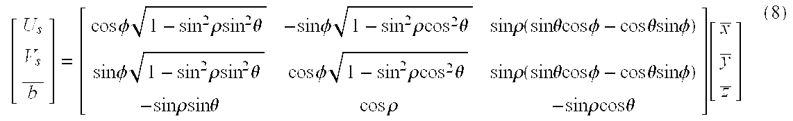
s) are each uniquely defined in terms of the reference coordinate system ({right arrow over (x)},{right arrow over (y)},{right arrow over (z)}) by the matrix relationship described in equation 8: [ U s V s b _ ] = [ cos φ 1 - sin 2 ρsin 2 θ - sin φ 1 - sin 2 ρcos 2 θ sin ρ ( sin θcos φ - cos θsin φ ) sin φ 1 - sin 2 ρsin 2 θ cos φ 1 - sin 2 ρcos 2 θ sin ρ ( sin θcos φ - cos θsin φ ) - sin ρsin θ cos ρ - sin ρcos θ ] [ x _ y _ z _ ] ( 8 )
Figure US06317127-20011113-M00005
As a result, each sensor's artesian coordinates (xs,ys) can be mapped into vectors {right arrow over (q)}(s,xs,ys) 72 from the center of the virtual sphere to a point on the virtual sphere using the following equations: x = x s - x off f s ( 9 ) y = y s - y off f s ( 10 ) q ( s , x s , y s ) = b s - V s y - U s x || b s - V s y - U s x || ( 11 )
Figure US06317127-20011113-M00006
where xoff and yoff are the offsets from the upper left hand corner of the sensor to its center and fs is its focal length.
The overlay symbols and audio tracks are registered to the video signal by mapping their coordinates to vectors {right arrow over (o)}(xo,yo) 74 on the virtual sphere. This is accomplished by first computing a vector between the center of the sphere in terms of its longitude, latitude, and altitude and the coordinates of the overlay symbol, applying a rotational transformation to compensate for the yaw, pitch, and roll of the sensor array, if applicable, and normalizing the vector to identify a point on the virtual sphere. As a result, landmarks in the video signal and their overlay symbols are registered to approximately the same point on the virtual sphere.
As shown in FIG. 4, each user has a coordinate system ({right arrow over (U)}u,{right arrow over (V)}u,{right arrow over (b)}u) 76 where {right arrow over (b)}u is a boresight vector that is perpendicular to the displayed subimage 42 and {right arrow over (U)}u,{right arrow over (V)}u are orthogonal vectors in the plane of the subimage. The vertex (0,0,0) of the coordinate system is fixed at the center 58 of the virtual sphere 54, but the component vectors track the user's head movement (ρ,θ,φ) that defines the current user FOV 46 as the user looks around inside the virtual sphere where ρ represents up-and-down movement, θ represents left-to-right movement, and φ represents side-to-side tilt.
The user's coordinate system ({right arrow over (U)}u,{right arrow over (V)}u,{right arrow over (b)}u is continuously updated in terms of the fixed reference coordinate system ({right arrow over (x)},{right arrow over (y)},{right arrow over (z)}) using the matrix relation shown in equation 8. The only difference being that the (ρ,θ,φ) values for the users change constantly whereas the (ρ,θ,φ) values for the sensors are fixed.
The user's image plane cartesian coordinates (xu,yu) are mapped into vectors {right arrow over (q)}(s,xu,yu) 78 from the center of the virtual sphere to a point on the virtual sphere using the following equations: x = x u - x off1 f u ( 12 ) y = y u - y off1 f u ( 13 ) q ( x u , y u ) = b u - V u y - U u x || b u - V u y - U i x || ( 14 )
Figure US06317127-20011113-M00007
where xoff1 and yoff1 are the offsets from the upper left hand corner of the subimage to its center and fu is the user's focal length.
FIG. 5 is a flowchart of a cartesian-to-spherical coordinate transformation engine 80 that is based upon the coordinate systems and mappings defined in FIGS. 2-4 and used to generate both source (s,xs,ys)-to-(d,n) and user (d,n)-to-(xu, yu) tables that facilitate an efficient mapping from the sensor pixels onto the virtual sphere and then onto the users' HMDs. The engine receives as inputs the desired resolution, and the object's focal length, orientation and cartesian coordinates (x,y) on the object's image plane where the object is either the image source or the user display, and generates output (x,y)-to-(d,n) tables. The user table is then inverted to produce the required (d,n)-to-(xu,yu) table.
In step 82, the engine defines the coordinate systems and mappings between them including: the reference coordinate system ({right arrow over (x)},{right arrow over (y)},{right arrow over (z)}), the indexed virtual sphere (equations 1-2), the mapping from an object's image plane cartesian coordinates to vectors on the sphere (equations 8-14), and the mapping from vectors to index pairs (d,n) (equations 6-7). The indexing of the virtual sphere is a function of the angular resolution. The mapping from the object's cartesian coordinates to vectors on the sphere is a function of the object's orientation (ρ,θ,φ) and its focal length. In step 84, the engine maps object pixels (x,y) to vectors {right arrow over (q)} on the sphere. In step 86, the engine maps the vectors {right arrow over (q)} into respective (d,n) index pairs. Lastly, the engine combines the results of steps 84 and 86 to generate a table that maps pixels (x,y) into (d,n) index pairs (step 88).
As shown in FIG. 6, the video signals 14, as shown in FIG. 1, are generated continuously (step 90) and directed to the distribution bus. In step 92, the engine 80 illustrated in FIG. 5 is used to generate source tables (s,xs,ys)-to-(d,n) based upon each image source's orientation in the reference coordinate system, the desired angular resolution, and the focal lengths. In step 94, each local processor uses the engine to generate user tables (d,n)-to-(xu,yu) based upon the user's current FOV, the desired angular resolution, and the focal lengths. The user tables are updated as the user's FOV or focal length changes. In step 96, the source and user tables are used to map the source pixels (s,xs,ys,i) to the user pixels (xu,yu,i), which are then transmitted to the user's HMD for display (step 98). The pixel value i is the intensity or color at each corresponding pixel. This augmented reality system can be implemented in a low complexity fixed angular resolution system, as shown in FIG. 7, or in a higher complexity but variable resolution system as shown in FIG. 8. This approach directly provides the desired uniformed angular resolution as well as distortion correction, which would normally be computed independently. In addition, the simplicity of the mapping itself and the resulting indexed representation on the virtual sphere support high resolution video, real-time response and multiple users.
As shown in FIG. 7, the low complexity fixed angular resolution system 100 is implemented by generating the source tables once at the source processor with a discrete angular resolution α (step 102), mapping the source pixels (s,xs,ys,i) into triplets (d,n,i) (step 104), and broadcasting them over the bus (step 106). As a result the source table does not have to be updated and the intensity values i having the same (d,n) index pairs can be averaged prior to broadcast. This reduces the computational load and the required bandwidth.
The tradeoff is that the maximum angular resolution available to each user is fixed at α. If a user zooms in to a point where the display resolution would be greater than α, pixel replication occurs which limits the true resolution to α. This problem can be effectively avoided by selecting a very fine α, however this limits the bandwidth savings that can be achieved by averaging. If the user zooms out to a point where the display resolution is less than α, some type of nearest neighbor algorithm is used to map the more finely resolved source (d,n) index pairs to the more coarsely resolved user (d,n) pairs. Typical algorithms are pixel-to-pixel, which results in a subsampling of the available data, pixel-to-pixel with a radius, which maps all the source pixels within one radius of the user pixel to that pixel thereby averaging the intensity values, and patch-to-pixel that operates similarly to the pixel-to-pixel with a radius.
Each local processor initializes the user table (d,n)-to-(xu,yu) (step 108), and then updates the user table (step 110) as the user looks around in the virtual sphere and zooms in and out on the displayed subimage. The local processor identifies the corner (d,n) index pairs (step 112) and then extracts all the triplets (d,n,i) off of the bus that lie within the boundary defined by the corner index pairs (step 114). The local processor then maps the intensity values for each (d,n) index pair to the corresponding cartesian coordinate (xu,yu) using this updated user table (step 116) and transmits the (xu,yu,i) to the HMD, which in turn displays the subimage.
As shown in FIG. 8, the higher complexity variable resolution system 118 is implemented by broadcasting the raw pixel data (s,xs,ys,i) over the video bus (step 119). This allows each user to extract the raw pixel data and process it up to the limiting angular resolution of the image sources. However, the source tables must be calculated by each user and updated periodically. Furthermore, more bandwidth is required to broadcast the raw pixel data than is required to broadcast the triplets (d,n,i). Each local processor initializes a source-to-user table (s,xs,ys)-to-(xu,yu) (step 120) by computing the individual source and user tables and combining them. The local processor updates the source-to-user table (step 122) as the user looks around in the virtual sphere and zooms in and out on the displayed subimage. The resolution of the table automatically changes to match the user's focal length. The local processor determines the corner (xs,ys) pixels for each image source (step 124) and then extracts all the pixels (s,xs,ys,i) off of the bus that lie within the boundary defined by the corner pixels (step 126). The local processor then maps the intensity values for each (s,xs,ys) pixel to the corresponding cartesian coordinate (xu,yu) using the updated source-to-user table (step 128), interpolates intensity values for any gaps in the display, and transmits the (xu,yu,i) to the HMD, which in turn displays the subimage.
The source-to-user tables can be generated and updated in two distinctly different ways. First, the angular resolution α can be set to an approximately infinitesimal value, e.g. the floating point resolution of the computers such that the (d,n) index pairs have floating point values. As a result, the (d,n) pairs in the source table must be mapped to the (d,n) pairs in the user table. This is preferably accomplished using a nearest neighbor algorithm such as the pixel-to-pixel with a radius or the patch-to-pixel algorithms. As the user zooms in on the image, the resolution of the user (d,n) index pairs increases such that fewer source (d,n) index pairs are mapped to each user index pair. This effectively increases the resolution of the displayed image. Conversely, as the user zooms out on the image, the resolution of the user (d,n) index pairs is reduced such that a greater number of source (d,n) index pairs are mapped to each user index pair. Thus, more averaging occurs and the display resolution is reduced.
In the second approach, the angular resolution a can be set at a discrete value as a function of user focal length such that the (d,n) index pairs, rounded to the nearest integer, are in approximately 1-to-1 correspondence with pixels in the user's focal plane. The relationship between user focal length and angular resolution is given as follows: α = pixel size f u ( 15 )
Figure US06317127-20011113-M00008
This provides the desired angular resolution without requiring an intermediate mapping between the source and user (d,n) index pairs. The 1-to-1 mapping is only approximate due to the possibility that there may be gaps in the wide FOV video signal due to the arrangement of the image sources. As a result, a small number of user (d,n) index pairs may not have a source index pair match. This is remedied by interpolating the intensity values for neighboring index pairs.
A detailed block diagram of the local processor 48 is shown in FIG. 9. The viewpoint display unit 52 includes an offset generator 130 that responds to the updated user FOV, i.e. the (ρ,θ,φ) coordinates from the head tracker, by computing an offset between the updated subimage and the oversized subimage that is stored in the subimage capture unit 50. For example, the offset is suitably the x and y offsets from the upper left hand corner of the oversized subimage. The offset generator 130 sends the offsets to a buffer reader 132 that shifts a read pointer by the x and y offsets and sub-raster scans the requested subimage from the subimage capture unit 50. The buffer reader 132 then transmits the updated subimage 42 to the HMD.
The subimage capture unit 50 includes a viewport buffer 134 that stores the oversized subimage. The viewport buffer is suitably 10% to 20% larger than the displayed subimage. The contents of the viewport buffer are continuously refreshed as the wide FOV video signal is downloaded from the video bus 24. However, the user and source tables that are stored in a LUT 136, and hence, the FOV that defines the extent of the oversized subimage, are only refreshed when the difference between the updated user FOV (ρ,θ,φ) and the FOV that was employed to define the current oversized subimage has changed by more than some minimum offset. This reduces the computational load and reduces the chance that glitches may occur in the user display.
A buffer shifter 138 compares the x and y offsets from the offset generator 130 to minimum and maximums offsets. If the x and y offsets are less than the minimum or greater than the maximum then the requested subimage is too close to an edge of the oversized buffer such that any further movement could exceed the boundaries of the oversized subimage and cause a glitch. As a result, the buffer shifter 138 1) generates a signal to update the user table in the LUT 136 in accordance with the updated user FOV (ρ,θ,φ), 2) transmits a signal to the offset generator 130 to reset the offset, and 3) preferably shifts the contents in the viewport buffer 134 in accordance with the updated user FOV. If the user changes his FOV rapidly, the ability to the shift the contents will reduce any distortion or glitch in the displayed subimage.
A LUT controller 140 responds to the update signal from the buffer shifter 138 and the user's focal length to update the user table in the LUT 136, and if applicable, to update the source table. The user table is updated by recomputing the user's coordinate system ({right arrow over (U)}u,{right arrow over (V)}u,{right arrow over (b)}u) in accordance with the updated (ρ,θ,φ) coordinates (equation 8), recomputing the x″,y″ values in accordance with the user focal length (equations 12-13) and the cartesian coordinates of the oversized subimage, recomputing the vectors {right arrow over (q)}(s,xu,yu) (equation 14), and computing the user index pairs (d,n) (equations 6-7). When the angular resolution is selected as a function of user focal length, the values for N and D, in equations 6-7 are changed according to equations 15, 1 and 2. The source table, if included at the local processor, is only updated when the angular resolution is selected in this manner and only for changes in focal length.
A subimage extractor 142 reads out the (d,n) index pairs or the source pixels (s,xs,ys) from the LUT 136 that lie within the updated oversized subimage, monitors the wide FOV video signal as it is transmitted over the video bus 24, and extracts the identified index pairs or source pixels. A pixel mapper 144 uses the user or source-to-user tables to map the intensity values for the extracted index pairs or pixels, respectively, into the cartesian coordinates of the oversized subimage and writes the intensities into the viewport buffer 134. If multiple intensity values are extracted for the same index pair or pixel, the pixel mapper 144 averages the intensity values. If there is a gap in the oversized subimage, the pixel mapper interpolates the intensity values for neighboring pixels to fill in the gap. The buffer reader 132 is preferably synchronized to the refresh rate of the viewport buffer 134 such that displayed subimage is refreshed at the same rate.
An overlay generator 146 receives the current oversized FOV from the buffer shifter 138, the user focal length, and any user selections such as specific classes as inputs. When all of the overlay data for the current wide FOV video signal is registered to the video signal and broadcast as (d,n) index pairs or (s,xs,ys) pixels plus the symbol or audio track, the overlay generator 146 extracts those symbols or audio tracks in the classes selected by the user, at the hierarchical resolution selected by the user focal length, and identified by the user or source-to-user tables from the bus 36. Alternately, the overlay generator 146 can use the GPS coordinates, the selected classes and user focal length to directly request only the desired symbols from the database. The overlay generator 146 passes the index pair (d,n) or pixel (s,xs,ys), typically the centroid of the symbol, to the pixel mapper 144, which returns the cartesian coordinates in the viewport buffer 134. Thereafter, the overlay generator 146 writes the overlay symbols into a second layer of the viewport buffer 134 such that they are registered to the landmarks in the video signal. The audio tracks are sent directly to the HMD, which if equipped with a spatial audio system can playback the audio tracks such that the appear to emanate from the designated coordinates in the displayed subimage or can provide a standard narrative that describes the associated landmark.
FIG. 10 shows an implementation of the augmented reality system 10 on an airplane 150. A multi-sensor system 152 is attached to the underside of the airplane to image a wide FOV 153 of the hemisphere below the plane. The airplane carries a Global Positioning System (GPS) 154 that provides the plane's current position in coordinates (longitude, latitude, altitude) in a global cartesian coordinate system and the plane's heading in terms of its yaw, pitch and roll (α,β,γ). A known GPS system is described by Orlando et al., “GPS-Squitter: System Concept, Performance, and Development Program” The Lincoln Laboratory Journal, Vol. y, No. 2, 1994, pp. 271-293. A server 156 digitizes the video signals generated by each sensor, maps them into (d,n) index pairs, and multiplexes them into a wide FOV video signal 157 that is distributed over a video bus 158 to a plurality of passengers 159. The server also extracts the overlay symbols and audio tracks in the current wide FOV, registers them to the wide FOV video signal, and broadcasts them over the bus. Alternatively, each user could request the symbols on-demand based on the current position and local FOV.
As particularly shown on an enlarged inset 163, each of the passengers wears a HMD 160 to view a subimage 161 of the wide FOV video signal. The passengers look around inside the virtual sphere to independently select and view a certain portion of the available wide FOV. Virtual I/O, Inc. produces a personal display system called i-glasses! that is suitable for use in a commercial airplane environment. Hughes Training, Inc. produces a high end ClearVue™ HMD that is typically used in military applications but could be adapted for use in the augmented reality system. The HMD 160 is fitted with an audio system 162 and a tracking device 164,such as an RF beacon or a gyro compass. The tracking device follows the user's head movement and outputs (ρ,θ) or (ρ,θ,φ) coordinates that define the users FOV 166. Crystal River Engineering produces an Alphatron 3D sound card that spatializes the inputs to the audio system 162 so that the user is immersed in 3D sound. A zoom controller 168 such as a knob can be placed on the HMD to allow the passenger to zoom in and out on the video signal. Alternatively, a video screen could be positioned on the seatback in front of the passenger with a joystick used to select the local FOV. A local processor downloads digital video signal, overlay symbols and audio tracks from the distribution bus, decompresses the video signal, extracts the desired subimage from the video signal in response to the user's FOV, displays the subimage and its associated symbols on the HMD 160, and plays the audio tracks over audio system 162.
The multi-sensor system 152 preferably includes a 4×4 geodesic array of sensors 170, preferably color CCD video cameras, that are each fitted with a hemispheric “fish eye” lens 172. A second sensor array can be placed on top of the airplane for viewing star constellations, for example. The system preferably image 4π steradians of visual field in the hemisphere below the airplane. To adequately cover the visual field at two times eye limiting resolution, 1K×1K pixelated CCD color cameras are used with each covering 4π steradians or roughly 45° in the horizontal and vertical FOV. Suitable CCD color cameras are produced by Hitachi, Inc. and Panasonic, Inc. The multi-sensor system produces sixteen subimage which are processed to form the individual analog video signals. Alternately, fewer higher resolution cameras could be used.
Imaging the region below the airplane onto the sensor array introduces three types of distortion into the wide FOV video signal 157: perspective, lens, and edger distortion. Perspective distortion is unavoidable, and is caused by the perspective view of the earth 174 from the sensors array. The region directly below the airplane at the center of the array's FOV is sensed with greater resolution than regions towards the periphery of its FOV. Thus, objects towards the periphery appear progressively closer together and are perspectively distorted.
Lens distortion results from the physical properties of the fish eye lens 172, which cause the pixels towards the edges of the CCDs to subtend progressively larger angles. This exacerbates the perspective distortion. Processing techniques for correcting the fish eye distortion are well known and included at the server. Edge distortion is caused by tiling the 4×4 CCD sensors together into a geodesically shaped array. In this configuration, the 16 subimages 49 sensed by the individuals CCDs do not match at their adjoining edges. However, the mapping from the cartesian coordinate space onto the virtual sphere automatically corrects for edge distortion.
While several illustrative embodiments of the invention have been shown and described, numerous variations and alternate embodiments will occur to those skilled in the art. Such variations and alternate embodiments are contemplated, and can be made without departing from the spirit and scope of the invention as defined in the appended claims.

Claims (15)

We claim:
1. An augmented reality system for displaying landmarks to at least one user, comprising:
at least one image source positioned at a known orientation with respect to a center of a virtual sphere in which points on said virtual sphere are represented as spherical coordinate pairs (d,n) that respectively denote segments and rings of said virtual sphere, said image source generating video signals that together form a wide field of view (FOV) video signal having pixels (s, xs,ys,i) in which s identifies said image source, (xs, ys) are cartesian coordinates of pixels on an image plane of said image source, and i is a pixel value:
a source processor that maps said pixels (s,xs,ys,i) into spherical coordinate triplets (d,n,i);
a storage device that stores landmark data including overlay symbols and audio tracks that correspond to said wide FOV video signal;
a video bus for broadcasting the triplets (d,n,i) to multiple users;
a system for obtaining the user's viewpoint orientation;
at least one user display system, comprising:
a) a display for displaying a respective subimage of said wide FOV video signal with an image plane of said display represented in cartesian coordinates (xu,yu); and
b) a user controllable viewpoint selector for selecting said respective subimage in the wide FOV video signal wherein a center of said virtual sphere is defined as a fixed position of an user using said display; and
at least one local processor for:
mapping pixels (xu,yu) of said respective subimage to respective spherical coordinate pairs (d,n);
extracting from said video bus, a respective set of said spherical triplets (d,n,i) that correspond to said respective set of said spherical coordinate pairs (d,n), and
remapping said respective set of spherical triplets (d,n, i) to pixels (xu,yu,i) in said image plane, and
wherein said local processor, in response to user selection, is capable of mapping selected portions of said overlay symbols and audio tracks to cartesian coordinates (xu, yu) of said image plane.
2. The augmented reality system of claim 1, wherein said display and said user controllable viewpoint selector respectively comprise:
a head mounted display (HMD) that is worn by said user; and
a head tracker on said HMD that tracks head movements of said user.
3. The augmented reality system of claim 1, further comprising:
a distribution processor; and
wherein said system for obtaining the user's viewpoint orientation is capable of obtaining the position and heading of the user, and said distribution processor is capable of extracting in response to said position and heading, overlay symbols and audio tracks that correspond to said wide FOV video signal.
4. The augmented reality system of claim 3, further comprising:
an overlay distribution bus for distribution of overlay symbols and audio tracks.
5. The augmented reality system of claim 1, wherein said positioning system includes a Global Positioning Satellite System.
6. The augmented reality system of claim 1, wherein said user display system further comprises a user controllable zoom mechanism for zooming in and out on said respective subimage.
7. A method of providing an augmented reality system for displaying landmarks to at least one user, comprising the steps of:
defining a virtual sphere in which points on said virtual sphere are represented as spherical coordinate pairs (d,n) that respectively denote segments and rings of said virtual sphere and a center of said virtual sphere is defined as a fixed position of said user;
generating at least one video signal from a known orientation in said virtual sphere that forms a wide field-of-view (FOV) video signal having pixels (s,xs,ys,i) in which s identities said video signal, (xs, ys) are cartesian coordinates of pixels within said video signal, and i is a pixel value;
mapping said pixels (s,xs,ys,i) into spherical coordinate triplets (d,n,i);
broadcasting said spherical coordinate triplets (d,n,i) over a video bus to said at least one user;
tracking a viewpoint orientation for said user that defines a subimage in said wide FOV video signal;
in response to said viewpoint orientation, mapping cartesian coordinates (xu,yu) of pixels in a user display to respective spherical coordinate pairs (d, n);
in response to said mapping steps, identifying a set of said spherical coordinate (d,n,i) triplets that corresponds to said subimage;
in response to said identifying step, remapping said set of spherical coordinate (d,n,i) triplets to pixels (xu,yu,i) in said user display;
storing landmark data including overlay symbols and audio tracks that correspond to said wide FOV video signal; and
in response to user selection, providing respective portions of said landmark data that are within said subimage to said user display.
8. The method of claim 7, wherein said defining step includes the step of generating said spherical coordinate pairs (d,n) with an angular resolution α and further including a step of adjusting a focal length for said user to zoom in and out on said subimage.
9. The method of claim 7, further comprising the steps of:
obtaining the position and heading of said user; and
in response to said position and heading, providing respective portions of said overlay symbols and audio tracks to said user display that are within said subimage; and
wherein said providing step includes the steps of:
registering said overlay symbols and audio tracks to respective spherical coordinate pairs (d,n);
in response to said registering step, extracting said respective portions; and
mapping said respective portions to said user display.
10. The method of claim 9, wherein the step of providing respective portions of said overlay symbols and audio tracks comprises distributing said respective portions over an overlay distribution bus.
11. The method of claim 7, wherein said user display is a head mounted display and said tracking step includes the step of monitoring the head movement of said user to establish said viewpoint orientation.
12. The method of claim 7, wherein said obtaining step includes the step of employing a Global Positioning Satellite System.
13. An airplane fitted with an augmented reality system for displaying landmarks to the user, comprising:
a plurality of sensors each attached to the underside of the airplane and providing a video signal of the hemisphere below the airplane;
a server for digitizing the video signal provided by each of said plurality of sensors, mapping the video signal into spherical coordinate (d,n) pairs and multiplexing the video signal provided by each one of said plurality of sensors into a wide field of view (FOV) signal, wherein the server also broadcasts landmark data including overlay symbols and audio tracks corresponding to the wide FOV signal;
a video bus for distributing said wide FOV signal to a plurality of passengers on board said airplane;
a system for obtaining the viewpoint orientation of each one of said plurality of passengers;
user display systems, each said display system comprising:
a) a display for displaying a respective subimage of said wide FOV video signal with an image plane ot said display represented in cartesian coordinates (xu,yu); and
b) a user controllable viewpoint selector for selecting said respective subimage in the wide FOV video signal wherein a center of said virtual sphere is defined as a fixed position of the passenger using said display; and
local processors, wherein each local processor is for;
mapping pixels (xu,yu) of said respective subimage to respective spherical coordinate pairs (d,n);
extracting from said video bus, a respective set of spherical triplets (d,n,i) that correspond to said respective spherical coordinate pairs (d,n), and
remapping said respective set of spherical triplets (d,n,i) to pixels (xu,yu,i) in said image plane, and
wherein each said local processor, in response to user selection is capable of mapping selected portions of said overlay symbols and audio tracks to cartesian coordinates (xu, yu) of said image plane.
14. The airplane of claim 13, wherein said system for obtaining the viewpoint orientation includes a subsystem for obtaining the positioning and heading of the passenger.
15. The airplane of claim 14, wherein said subsystem is a Global Positioning System.
US08/731,542 1996-10-16 1996-10-16 Multi-user real-time augmented reality system and method Expired - Lifetime US6317127B1 (en)

Priority Applications (3)

Application Number Priority Date Filing Date Title
US08/731,542 US6317127B1 (en) 1996-10-16 1996-10-16 Multi-user real-time augmented reality system and method
EP97117443A EP0838787A3 (en) 1996-10-16 1997-10-09 A multi-user real-time virtual reality system and method
JP9283931A JPH10243310A (en) 1996-10-16 1997-10-16 Real time emphasized reality system for many users and its method

Applications Claiming Priority (1)

Application Number Priority Date Filing Date Title
US08/731,542 US6317127B1 (en) 1996-10-16 1996-10-16 Multi-user real-time augmented reality system and method

Publications (1)

Publication Number Publication Date
US6317127B1 true US6317127B1 (en) 2001-11-13

Family

ID=24939967

Family Applications (1)

Application Number Title Priority Date Filing Date
US08/731,542 Expired - Lifetime US6317127B1 (en) 1996-10-16 1996-10-16 Multi-user real-time augmented reality system and method

Country Status (3)

Country Link
US (1) US6317127B1 (en)
EP (1) EP0838787A3 (en)
JP (1) JPH10243310A (en)

Cited By (85)

* Cited by examiner, † Cited by third party
Publication number Priority date Publication date Assignee Title
US20030227542A1 (en) * 2001-12-20 2003-12-11 Xiang Zhang Single-computer real-time stereo augmented reality system
US20040104934A1 (en) * 2001-06-19 2004-06-03 Fager Jan G. Device and a method for creating an environment for a creature
US20040119662A1 (en) * 2002-12-19 2004-06-24 Accenture Global Services Gmbh Arbitrary object tracking in augmented reality applications
US6774869B2 (en) * 2000-12-22 2004-08-10 Board Of Trustees Operating Michigan State University Teleportal face-to-face system
US20040199923A1 (en) * 2003-04-07 2004-10-07 Russek David J. Method, system and software for associating atributes within digital media presentations
US20040201677A1 (en) * 2001-04-25 2004-10-14 Barry Bronson Method and apparatus for providing subimages to remote sites
US6898307B1 (en) * 1999-09-22 2005-05-24 Xerox Corporation Object identification method and system for an augmented-reality display
US20050219240A1 (en) * 2004-04-05 2005-10-06 Vesely Michael A Horizontal perspective hands-on simulator
US20050227560A1 (en) * 2004-03-29 2005-10-13 Allred Jimmie B Iii Flexible carbon-fiber laminates
WO2005098517A2 (en) * 2004-04-05 2005-10-20 Vesely Michael A Horizontal perspective hand-on simulator
US20050248566A1 (en) * 2004-04-05 2005-11-10 Vesely Michael A Horizontal perspective hands-on simulator
US20060055628A1 (en) * 2004-09-14 2006-03-16 The Boeing Company Situational awareness components of an enhanced vision system
US20060269437A1 (en) * 2005-05-31 2006-11-30 Pandey Awadh B High temperature aluminum alloys
US7161616B1 (en) * 1999-04-16 2007-01-09 Matsushita Electric Industrial Co., Ltd. Image processing device and monitoring system
US20070015586A1 (en) * 2005-07-14 2007-01-18 Huston Charles D GPS Based Spectator and Participant Sport System and Method
US20070076920A1 (en) * 2005-10-04 2007-04-05 Microsoft Corporation Street side maps and paths
US20070117576A1 (en) * 2005-07-14 2007-05-24 Huston Charles D GPS Based Friend Location and Identification System and Method
US7289130B1 (en) * 2000-01-13 2007-10-30 Canon Kabushiki Kaisha Augmented reality presentation apparatus and method, and storage medium
US20070273557A1 (en) * 2006-05-26 2007-11-29 Itt Manufacturing Enterprises,Inc. Augmented reality-based system and method providing status and control of unmanned vehicles
US20070273610A1 (en) * 2006-05-26 2007-11-29 Itt Manufacturing Enterprises, Inc. System and method to display maintenance and operational instructions of an apparatus using augmented reality
US7312766B1 (en) * 2000-09-22 2007-12-25 Canadian Space Agency Method and system for time/motion compensation for head mounted displays
US20080005702A1 (en) * 2006-05-31 2008-01-03 Abb Technology Ltd. Virtual work place
US20080036653A1 (en) * 2005-07-14 2008-02-14 Huston Charles D GPS Based Friend Location and Identification System and Method
US20080186255A1 (en) * 2006-12-07 2008-08-07 Cohen Philip R Systems and methods for data annotation, recordation, and communication
US20080198230A1 (en) * 2005-07-14 2008-08-21 Huston Charles D GPS Based Spectator and Participant Sport System and Method
US20080218331A1 (en) * 2007-03-08 2008-09-11 Itt Manufacturing Enterprises, Inc. Augmented reality-based system and method to show the location of personnel and sensors inside occluded structures and provide increased situation awareness
US20080259096A1 (en) * 2005-07-14 2008-10-23 Huston Charles D GPS-Based Location and Messaging System and Method
US20090054084A1 (en) * 2007-08-24 2009-02-26 Motorola, Inc. Mobile virtual and augmented reality system
US20090081959A1 (en) * 2007-09-21 2009-03-26 Motorola, Inc. Mobile virtual and augmented reality system
US20090111434A1 (en) * 2007-10-31 2009-04-30 Motorola, Inc. Mobile virtual and augmented reality system
US20090137860A1 (en) * 2005-11-10 2009-05-28 Olivier Lordereau Biomedical Device for Treating by Virtual Immersion
US7554511B2 (en) * 2001-06-19 2009-06-30 Faeger Jan G Device and a method for creating an environment for a creature
US20090237328A1 (en) * 2008-03-20 2009-09-24 Motorola, Inc. Mobile virtual and augmented reality system
US7693702B1 (en) * 2002-11-01 2010-04-06 Lockheed Martin Corporation Visualizing space systems modeling using augmented reality
US20100188506A1 (en) * 2009-01-28 2010-07-29 Honeywell International Inc. Synthetic window for limited visibility vehicles
US20100194782A1 (en) * 2009-02-04 2010-08-05 Motorola, Inc. Method and apparatus for creating virtual graffiti in a mobile virtual and augmented reality system
US20100214111A1 (en) * 2007-12-21 2010-08-26 Motorola, Inc. Mobile virtual and augmented reality system
US7796155B1 (en) 2003-12-19 2010-09-14 Hrl Laboratories, Llc Method and apparatus for real-time group interactive augmented-reality area monitoring, suitable for enhancing the enjoyment of entertainment events
US7796134B2 (en) 2004-06-01 2010-09-14 Infinite Z, Inc. Multi-plane horizontal perspective display
US7907167B2 (en) 2005-05-09 2011-03-15 Infinite Z, Inc. Three dimensional horizontal perspective workstation
US20110065496A1 (en) * 2009-09-11 2011-03-17 Wms Gaming, Inc. Augmented reality mechanism for wagering game systems
US20110063432A1 (en) * 2000-10-06 2011-03-17 Enrico Di Bernardo System and method for creating, storing and utilizing images of a geographic location
US20110122130A1 (en) * 2005-05-09 2011-05-26 Vesely Michael A Modifying Perspective of Stereoscopic Images Based on Changes in User Viewpoint
US20110187706A1 (en) * 2010-01-29 2011-08-04 Vesely Michael A Presenting a View within a Three Dimensional Scene
US20110237254A1 (en) * 2010-03-25 2011-09-29 Jong Hyup Lee Data integration for wireless network systems
US20120092341A1 (en) * 1995-11-15 2012-04-19 Grandeye, Ltd. Methods for 3D world simulator environment
US20120113092A1 (en) * 2010-11-08 2012-05-10 Avi Bar-Zeev Automatic variable virtual focus for augmented reality displays
US20120164938A1 (en) * 2010-12-23 2012-06-28 Electronics And Telecommunications Research Institute System and method for providing augmented reality contents based on broadcasting
US20130208187A1 (en) * 2009-03-20 2013-08-15 International Business Machines Corporation Digital video recorder broadcast overlays
US8589488B2 (en) 2005-07-14 2013-11-19 Charles D. Huston System and method for creating content for an event using a social network
US20140192084A1 (en) * 2013-01-10 2014-07-10 Stephen Latta Mixed reality display accommodation
US8786529B1 (en) 2011-05-18 2014-07-22 Zspace, Inc. Liquid crystal variable drive voltage
US20150363656A1 (en) * 2014-06-13 2015-12-17 B/E Aerospace, Inc. Apparatus and method for providing attitude reference for vehicle passengers
US9304319B2 (en) 2010-11-18 2016-04-05 Microsoft Technology Licensing, Llc Automatic focus improvement for augmented reality displays
US9323325B2 (en) 2011-08-30 2016-04-26 Microsoft Technology Licensing, Llc Enhancing an object of interest in a see-through, mixed reality display device
US9344842B2 (en) 2005-07-14 2016-05-17 Charles D. Huston System and method for viewing golf using virtual reality
US20160155271A1 (en) * 2012-02-28 2016-06-02 Blackberry Limited Method and device for providing augmented reality output
US9424579B2 (en) 2011-03-22 2016-08-23 Fmr Llc System for group supervision
US20170154455A1 (en) * 2015-11-27 2017-06-01 Samsung Electronics Co., Ltd. Electronic device and method for displaying and generating panoramic image
US9939890B2 (en) 2014-07-03 2018-04-10 Sony Interactive Entertainment Inc. Image generation apparatus and image generation method of generating a wide viewing angle image
US9958934B1 (en) * 2006-05-01 2018-05-01 Jeffrey D. Mullen Home and portable augmented reality and virtual reality video game consoles
US20180124330A1 (en) * 2016-10-27 2018-05-03 Leica Geosystems Ag Method for visually representing scanning data
US9965471B2 (en) 2012-02-23 2018-05-08 Charles D. Huston System and method for capturing and sharing a location based experience
US10089544B2 (en) 2014-06-13 2018-10-02 B/E Aerospace, Inc. Apparatus and method for providing attitude reference for vehicle passengers
WO2018199701A1 (en) * 2017-04-28 2018-11-01 Samsung Electronics Co., Ltd. Method for providing content and apparatus therefor
US10169917B2 (en) 2015-08-20 2019-01-01 Microsoft Technology Licensing, Llc Augmented reality
US10235808B2 (en) 2015-08-20 2019-03-19 Microsoft Technology Licensing, Llc Communication system
US10422996B2 (en) 2015-10-14 2019-09-24 Samsung Electronics Co., Ltd. Electronic device and method for controlling same
US10452934B1 (en) 2014-06-13 2019-10-22 B/E Aerospace, Inc. Apparatus and method for providing attitude reference for vehicle passengers
CN110488972A (en) * 2013-11-08 2019-11-22 高通股份有限公司 Feature tracking for the additional mode in spatial interaction
CN110786017A (en) * 2017-11-29 2020-02-11 近江数码制造株式会社 Distribution image generation method
US10558877B2 (en) 2014-06-13 2020-02-11 B/E Aerospace, Inc. Apparatus and method for providing attitude reference for vehicle passengers
US10600235B2 (en) 2012-02-23 2020-03-24 Charles D. Huston System and method for capturing and sharing a location based experience
US10614329B2 (en) 2014-06-13 2020-04-07 B/E Aerospace, Inc. Apparatus and method for providing attitude reference for vehicle passengers
US20200115056A1 (en) * 2018-10-11 2020-04-16 Rockwell Collins, Inc. Aircraft Based Augmented and Virtual Reality Passenger Social Media Interaction System and Related Method
US10692409B2 (en) 2015-04-06 2020-06-23 Ricoh Company, Ltd. Information processing apparatus, information processing method, and computer program product for arranging a planar image in a full-spherical panoramic image obtained by imaging an omnidirectional range
US10937239B2 (en) 2012-02-23 2021-03-02 Charles D. Huston System and method for creating an environment and for sharing an event
US10949689B2 (en) 2014-06-13 2021-03-16 B/E Aerospace, Inc. Apparatus and method for providing attitude reference for vehicle passengers
US10958959B1 (en) * 2019-09-13 2021-03-23 At&T Intellectual Property I, L.P. Automatic generation of augmented reality media
CN112601065A (en) * 2019-10-01 2021-04-02 浙江大学 Method and device for reconstructing high-freedom video viewable range
US11176880B2 (en) * 2016-01-13 2021-11-16 Shenzhen Yunyinggu Technology Co., Ltd Apparatus and method for pixel data reordering
US11212331B1 (en) * 2018-10-26 2021-12-28 Snap Inc. Triggering changes to real-time special effects included in a live streaming video
US20220122233A1 (en) * 2018-11-16 2022-04-21 Zte Corporation Method and apparatus for presenting image for virtual reality device, device and non-transitory computer-readable storage medium
US11416064B2 (en) 2017-05-17 2022-08-16 Siemens Healthcare Diagnostics Inc. Alerts with augmented reality
US11483533B2 (en) 2021-01-05 2022-10-25 At&T Intellectual Property I, L.P. System and method for social immersive content rendering

Families Citing this family (10)

* Cited by examiner, † Cited by third party
Publication number Priority date Publication date Assignee Title
AU2001260002A1 (en) * 2000-06-02 2001-12-11 Eidgenossische Technische Hochschule Zurich, Gruppe Fur Graphische Datenverarbeitung, Institut Fur Wissenschaftliches Rechnen, ETH- Zentrum Method for the production of a virtual reality environment
JP2004534963A (en) * 2001-03-30 2004-11-18 コーニンクレッカ フィリップス エレクトロニクス エヌ ヴィ Methods, systems and devices for augmented reality
US7391424B2 (en) * 2003-08-15 2008-06-24 Werner Gerhard Lonsing Method and apparatus for producing composite images which contain virtual objects
EP2426929A1 (en) 2010-09-06 2012-03-07 Telefonaktiebolaget L M Ericsson AB (Publ) Viewpoint navigation
GB2535536B (en) * 2015-02-23 2020-01-01 Jaguar Land Rover Ltd Apparatus and method for displaying information
US11037202B2 (en) * 2016-12-27 2021-06-15 Paypal, Inc. Contextual data in augmented reality processing for item recommendations
EP3616035A1 (en) 2017-06-19 2020-03-04 Apple Inc. Augmented reality interface for interacting with displayed maps
WO2019003889A1 (en) * 2017-06-26 2019-01-03 ソニー株式会社 Generation device and generation method, and playback device and playback method
US10777007B2 (en) 2017-09-29 2020-09-15 Apple Inc. Cooperative augmented reality map interface
CN114125691A (en) * 2017-12-18 2022-03-01 杜比国际公司 Method and system for rendering audio signals in a virtual reality environment

Citations (10)

* Cited by examiner, † Cited by third party
Publication number Priority date Publication date Assignee Title
EP0592652A1 (en) 1992-04-30 1994-04-20 J.P. Producciones, S.L. Improved integral virtual reality and/or image recording, projection-visualization-listening system
US5384588A (en) * 1991-05-13 1995-01-24 Telerobotics International, Inc. System for omindirectional image viewing at a remote location without the transmission of control signals to select viewing parameters
US5422653A (en) 1993-01-07 1995-06-06 Maguire, Jr.; Francis J. Passive virtual reality
GB2289820A (en) 1994-05-27 1995-11-29 Eric Gullichsen Wide-angle image dewarping method and apparatus
US5488675A (en) * 1994-03-31 1996-01-30 David Sarnoff Research Center, Inc. Stabilizing estimate of location of target region inferred from tracked multiple landmark regions of a video image
EP0696018A2 (en) 1994-08-03 1996-02-07 Nippon Telegraph And Telephone Corporation Shared virtual space display method and apparatus using said method
WO1996021321A1 (en) 1995-01-06 1996-07-11 Anderson David P Virtual reality television system
US5748194A (en) * 1996-05-08 1998-05-05 Live Picture, Inc. Rendering perspective views of a scene using a scanline-coherent look-up table
US5841439A (en) * 1994-07-22 1998-11-24 Monash University Updating graphical objects based on object validity periods
US5905499A (en) * 1995-07-05 1999-05-18 Fakespace, Inc. Method and system for high performance computer-generated virtual environments

Patent Citations (10)

* Cited by examiner, † Cited by third party
Publication number Priority date Publication date Assignee Title
US5384588A (en) * 1991-05-13 1995-01-24 Telerobotics International, Inc. System for omindirectional image viewing at a remote location without the transmission of control signals to select viewing parameters
EP0592652A1 (en) 1992-04-30 1994-04-20 J.P. Producciones, S.L. Improved integral virtual reality and/or image recording, projection-visualization-listening system
US5422653A (en) 1993-01-07 1995-06-06 Maguire, Jr.; Francis J. Passive virtual reality
US5488675A (en) * 1994-03-31 1996-01-30 David Sarnoff Research Center, Inc. Stabilizing estimate of location of target region inferred from tracked multiple landmark regions of a video image
GB2289820A (en) 1994-05-27 1995-11-29 Eric Gullichsen Wide-angle image dewarping method and apparatus
US5841439A (en) * 1994-07-22 1998-11-24 Monash University Updating graphical objects based on object validity periods
EP0696018A2 (en) 1994-08-03 1996-02-07 Nippon Telegraph And Telephone Corporation Shared virtual space display method and apparatus using said method
WO1996021321A1 (en) 1995-01-06 1996-07-11 Anderson David P Virtual reality television system
US5905499A (en) * 1995-07-05 1999-05-18 Fakespace, Inc. Method and system for high performance computer-generated virtual environments
US5748194A (en) * 1996-05-08 1998-05-05 Live Picture, Inc. Rendering perspective views of a scene using a scanline-coherent look-up table

Non-Patent Citations (8)

* Cited by examiner, † Cited by third party
Title
"Alphatron Affordable 3D Sound", Crystal River Engineering Brochure, 1995.
"ClearVue Low-Cost Helmet-Mounted Display", Hughes Training, Inc. Brochure, Link Division, 1995.
"i-glasses", Virtual I/O, Inc. Brochure, 1994.
"Molly", Fakespace, Inc. Brochure, 1995.
"Virtual Reality: Scientific and Technological Challenges", National Research Council, Nathaniel Durlach and Anne Mavor, Eds, National Academy Press, 1995, pp. 17-23.
Hirose et al., Transmission of Realistic Sensation: Development of Virtual Dome, IEEE Vrais, vol. 1363, Jan. 1993, pp. 125-131.
Orlando et al., "GPS-Squitter: System Concept, Performance, and Development Program", The Laboratory Journal, vol. y, No. 2, 1994, pp. 271-293.
Warren Robinett, "Interactivity and Individual Viewpoint in Shared Virtual Worlds: The Big Screen vs. Networked Personal Displays," Computer Graphics, US, ACM, vol. 28, No. 2, May 1994, pp. 127-130.

Cited By (161)

* Cited by examiner, † Cited by third party
Publication number Priority date Publication date Assignee Title
US20120092341A1 (en) * 1995-11-15 2012-04-19 Grandeye, Ltd. Methods for 3D world simulator environment
US7161616B1 (en) * 1999-04-16 2007-01-09 Matsushita Electric Industrial Co., Ltd. Image processing device and monitoring system
US6898307B1 (en) * 1999-09-22 2005-05-24 Xerox Corporation Object identification method and system for an augmented-reality display
US7289130B1 (en) * 2000-01-13 2007-10-30 Canon Kabushiki Kaisha Augmented reality presentation apparatus and method, and storage medium
US7312766B1 (en) * 2000-09-22 2007-12-25 Canadian Space Agency Method and system for time/motion compensation for head mounted displays
US8818138B2 (en) 2000-10-06 2014-08-26 Enrico Di Bernardo System and method for creating, storing and utilizing images of a geographical location
US8213749B2 (en) 2000-10-06 2012-07-03 Verderi, LLC System and method for creating, storing and utilizing images of a geographic location
US20110063432A1 (en) * 2000-10-06 2011-03-17 Enrico Di Bernardo System and method for creating, storing and utilizing images of a geographic location
US9644968B2 (en) 2000-10-06 2017-05-09 Vederi, Llc System and method for creating, storing and utilizing images of a geographical location
US10473465B2 (en) 2000-10-06 2019-11-12 Vederi, Llc System and method for creating, storing and utilizing images of a geographical location
US20050083248A1 (en) * 2000-12-22 2005-04-21 Frank Biocca Mobile face capture and image processing system and method
US6774869B2 (en) * 2000-12-22 2004-08-10 Board Of Trustees Operating Michigan State University Teleportal face-to-face system
US20040201677A1 (en) * 2001-04-25 2004-10-14 Barry Bronson Method and apparatus for providing subimages to remote sites
US7148914B2 (en) * 2001-04-25 2006-12-12 Hewlett-Packard Development Company, L.P. Method and apparatus for providing subimages to remote sites
US7554511B2 (en) * 2001-06-19 2009-06-30 Faeger Jan G Device and a method for creating an environment for a creature
US20040104934A1 (en) * 2001-06-19 2004-06-03 Fager Jan G. Device and a method for creating an environment for a creature
US20030227542A1 (en) * 2001-12-20 2003-12-11 Xiang Zhang Single-computer real-time stereo augmented reality system
US7693702B1 (en) * 2002-11-01 2010-04-06 Lockheed Martin Corporation Visualizing space systems modeling using augmented reality
US7050078B2 (en) * 2002-12-19 2006-05-23 Accenture Global Services Gmbh Arbitrary object tracking augmented reality applications
US20040119662A1 (en) * 2002-12-19 2004-06-24 Accenture Global Services Gmbh Arbitrary object tracking in augmented reality applications
US10679255B2 (en) 2003-04-07 2020-06-09 10Tales, Inc. Method, system and software for associating attributes within digital media presentations
US8856030B2 (en) 2003-04-07 2014-10-07 Sevenecho, Llc Method, system and software for associating attributes within digital media presentations
US20040267816A1 (en) * 2003-04-07 2004-12-30 Russek David J. Method, system and software for digital media narrative personalization
US20040199923A1 (en) * 2003-04-07 2004-10-07 Russek David J. Method, system and software for associating atributes within digital media presentations
US8478645B2 (en) 2003-04-07 2013-07-02 Sevenecho, Llc Method, system and software for digital media narrative personalization
US7796155B1 (en) 2003-12-19 2010-09-14 Hrl Laboratories, Llc Method and apparatus for real-time group interactive augmented-reality area monitoring, suitable for enhancing the enjoyment of entertainment events
US20050227560A1 (en) * 2004-03-29 2005-10-13 Allred Jimmie B Iii Flexible carbon-fiber laminates
US20050219240A1 (en) * 2004-04-05 2005-10-06 Vesely Michael A Horizontal perspective hands-on simulator
WO2005098517A2 (en) * 2004-04-05 2005-10-20 Vesely Michael A Horizontal perspective hand-on simulator
US20050248566A1 (en) * 2004-04-05 2005-11-10 Vesely Michael A Horizontal perspective hands-on simulator
WO2005098517A3 (en) * 2004-04-05 2006-04-27 Michael A Vesely Horizontal perspective hand-on simulator
US7796134B2 (en) 2004-06-01 2010-09-14 Infinite Z, Inc. Multi-plane horizontal perspective display
US8508435B2 (en) * 2004-09-14 2013-08-13 The Boeing Company Situational awareness components of an enhanced vision system
US8194002B2 (en) * 2004-09-14 2012-06-05 The Boeing Company Situational awareness components of an enhanced vision system
US20120249592A1 (en) * 2004-09-14 2012-10-04 The Boeing Company Situational Awareness Components of an Enhanced Vision System
US20060055628A1 (en) * 2004-09-14 2006-03-16 The Boeing Company Situational awareness components of an enhanced vision system
US20110122130A1 (en) * 2005-05-09 2011-05-26 Vesely Michael A Modifying Perspective of Stereoscopic Images Based on Changes in User Viewpoint
US7907167B2 (en) 2005-05-09 2011-03-15 Infinite Z, Inc. Three dimensional horizontal perspective workstation
US8717423B2 (en) 2005-05-09 2014-05-06 Zspace, Inc. Modifying perspective of stereoscopic images based on changes in user viewpoint
US9292962B2 (en) 2005-05-09 2016-03-22 Zspace, Inc. Modifying perspective of stereoscopic images based on changes in user viewpoint
US9684994B2 (en) 2005-05-09 2017-06-20 Zspace, Inc. Modifying perspective of stereoscopic images based on changes in user viewpoint
US20060269437A1 (en) * 2005-05-31 2006-11-30 Pandey Awadh B High temperature aluminum alloys
US10802153B2 (en) 2005-07-14 2020-10-13 Charles D. Huston GPS based participant identification system and method
US9566494B2 (en) 2005-07-14 2017-02-14 Charles D. Huston System and method for creating and sharing an event using a social network
US11087345B2 (en) 2005-07-14 2021-08-10 Charles D. Huston System and method for creating content for an event using a social network
US8933967B2 (en) 2005-07-14 2015-01-13 Charles D. Huston System and method for creating and sharing an event using a social network
US20070015586A1 (en) * 2005-07-14 2007-01-18 Huston Charles D GPS Based Spectator and Participant Sport System and Method
US8842003B2 (en) 2005-07-14 2014-09-23 Charles D. Huston GPS-based location and messaging system and method
US20070018880A1 (en) * 2005-07-14 2007-01-25 Huston Charles D GPS Based Situational Awareness and Identification System and Method
US7855638B2 (en) 2005-07-14 2010-12-21 Huston Charles D GPS based spectator and participant sport system and method
US9344842B2 (en) 2005-07-14 2016-05-17 Charles D. Huston System and method for viewing golf using virtual reality
US7518501B2 (en) 2005-07-14 2009-04-14 Huston Charles D GPS based situational awareness and identification system and method
US9445225B2 (en) 2005-07-14 2016-09-13 Huston Family Trust GPS based spectator and participant sport system and method
US8589488B2 (en) 2005-07-14 2013-11-19 Charles D. Huston System and method for creating content for an event using a social network
US9498694B2 (en) 2005-07-14 2016-11-22 Charles D. Huston System and method for creating content for an event using a social network
US20070117576A1 (en) * 2005-07-14 2007-05-24 Huston Charles D GPS Based Friend Location and Identification System and Method
US10512832B2 (en) 2005-07-14 2019-12-24 Charles D. Huston System and method for a golf event using artificial reality
US20080259096A1 (en) * 2005-07-14 2008-10-23 Huston Charles D GPS-Based Location and Messaging System and Method
US8417261B2 (en) 2005-07-14 2013-04-09 Charles D. Huston GPS based friend location and identification system and method
US20080036653A1 (en) * 2005-07-14 2008-02-14 Huston Charles D GPS Based Friend Location and Identification System and Method
US8275397B2 (en) 2005-07-14 2012-09-25 Huston Charles D GPS based friend location and identification system and method
US20080198230A1 (en) * 2005-07-14 2008-08-21 Huston Charles D GPS Based Spectator and Participant Sport System and Method
US8207843B2 (en) 2005-07-14 2012-06-26 Huston Charles D GPS-based location and messaging system and method
US9798012B2 (en) 2005-07-14 2017-10-24 Charles D. Huston GPS based participant identification system and method
US8249626B2 (en) 2005-07-14 2012-08-21 Huston Charles D GPS based friend location and identification system and method
US7840032B2 (en) * 2005-10-04 2010-11-23 Microsoft Corporation Street-side maps and paths
US20070076920A1 (en) * 2005-10-04 2007-04-05 Microsoft Corporation Street side maps and paths
US20090137860A1 (en) * 2005-11-10 2009-05-28 Olivier Lordereau Biomedical Device for Treating by Virtual Immersion
US7946974B2 (en) 2005-11-10 2011-05-24 Olivier Lordereau Biomedical device for treating by virtual immersion
US9958934B1 (en) * 2006-05-01 2018-05-01 Jeffrey D. Mullen Home and portable augmented reality and virtual reality video game consoles
US20070273557A1 (en) * 2006-05-26 2007-11-29 Itt Manufacturing Enterprises,Inc. Augmented reality-based system and method providing status and control of unmanned vehicles
US20070273610A1 (en) * 2006-05-26 2007-11-29 Itt Manufacturing Enterprises, Inc. System and method to display maintenance and operational instructions of an apparatus using augmented reality
US7920071B2 (en) 2006-05-26 2011-04-05 Itt Manufacturing Enterprises, Inc. Augmented reality-based system and method providing status and control of unmanned vehicles
US8046719B2 (en) * 2006-05-31 2011-10-25 Abb Technology Ltd. Virtual work place
US20080005702A1 (en) * 2006-05-31 2008-01-03 Abb Technology Ltd. Virtual work place
US20080186255A1 (en) * 2006-12-07 2008-08-07 Cohen Philip R Systems and methods for data annotation, recordation, and communication
US9324229B2 (en) 2007-03-08 2016-04-26 Exelis, Inc. System and method to display maintenance and operational instructions of an apparatus using augmented reality
US20080218331A1 (en) * 2007-03-08 2008-09-11 Itt Manufacturing Enterprises, Inc. Augmented reality-based system and method to show the location of personnel and sensors inside occluded structures and provide increased situation awareness
US20090054084A1 (en) * 2007-08-24 2009-02-26 Motorola, Inc. Mobile virtual and augmented reality system
US20090081959A1 (en) * 2007-09-21 2009-03-26 Motorola, Inc. Mobile virtual and augmented reality system
US7844229B2 (en) 2007-09-21 2010-11-30 Motorola Mobility, Inc Mobile virtual and augmented reality system
US7853296B2 (en) 2007-10-31 2010-12-14 Motorola Mobility, Inc. Mobile virtual and augmented reality system
US20090111434A1 (en) * 2007-10-31 2009-04-30 Motorola, Inc. Mobile virtual and augmented reality system
US20100214111A1 (en) * 2007-12-21 2010-08-26 Motorola, Inc. Mobile virtual and augmented reality system
US20090237328A1 (en) * 2008-03-20 2009-09-24 Motorola, Inc. Mobile virtual and augmented reality system
US20100188506A1 (en) * 2009-01-28 2010-07-29 Honeywell International Inc. Synthetic window for limited visibility vehicles
US20100194782A1 (en) * 2009-02-04 2010-08-05 Motorola, Inc. Method and apparatus for creating virtual graffiti in a mobile virtual and augmented reality system
US8350871B2 (en) 2009-02-04 2013-01-08 Motorola Mobility Llc Method and apparatus for creating virtual graffiti in a mobile virtual and augmented reality system
US20130208187A1 (en) * 2009-03-20 2013-08-15 International Business Machines Corporation Digital video recorder broadcast overlays
US9258512B2 (en) * 2009-03-20 2016-02-09 International Business Machines Corporation Digital video recorder broadcast overlays
US20110065496A1 (en) * 2009-09-11 2011-03-17 Wms Gaming, Inc. Augmented reality mechanism for wagering game systems
US8717360B2 (en) 2010-01-29 2014-05-06 Zspace, Inc. Presenting a view within a three dimensional scene
US20110187706A1 (en) * 2010-01-29 2011-08-04 Vesely Michael A Presenting a View within a Three Dimensional Scene
US9202306B2 (en) 2010-01-29 2015-12-01 Zspace, Inc. Presenting a view within a three dimensional scene
US9824485B2 (en) 2010-01-29 2017-11-21 Zspace, Inc. Presenting a view within a three dimensional scene
US20110237254A1 (en) * 2010-03-25 2011-09-29 Jong Hyup Lee Data integration for wireless network systems
US8521162B2 (en) 2010-03-25 2013-08-27 Jong Hyup Lee Data integration for wireless network systems
US8275375B2 (en) 2010-03-25 2012-09-25 Jong Hyup Lee Data integration for wireless network systems
US20120113092A1 (en) * 2010-11-08 2012-05-10 Avi Bar-Zeev Automatic variable virtual focus for augmented reality displays
US9292973B2 (en) * 2010-11-08 2016-03-22 Microsoft Technology Licensing, Llc Automatic variable virtual focus for augmented reality displays
US9588341B2 (en) 2010-11-08 2017-03-07 Microsoft Technology Licensing, Llc Automatic variable virtual focus for augmented reality displays
US9304319B2 (en) 2010-11-18 2016-04-05 Microsoft Technology Licensing, Llc Automatic focus improvement for augmented reality displays
US10055889B2 (en) 2010-11-18 2018-08-21 Microsoft Technology Licensing, Llc Automatic focus improvement for augmented reality displays
US20120164938A1 (en) * 2010-12-23 2012-06-28 Electronics And Telecommunications Research Institute System and method for providing augmented reality contents based on broadcasting
US9973630B2 (en) 2011-03-22 2018-05-15 Fmr Llc System for group supervision
US9424579B2 (en) 2011-03-22 2016-08-23 Fmr Llc System for group supervision
US9958712B2 (en) 2011-05-18 2018-05-01 Zspace, Inc. Liquid crystal variable drive voltage
US9134556B2 (en) 2011-05-18 2015-09-15 Zspace, Inc. Liquid crystal variable drive voltage
US8786529B1 (en) 2011-05-18 2014-07-22 Zspace, Inc. Liquid crystal variable drive voltage
US9323325B2 (en) 2011-08-30 2016-04-26 Microsoft Technology Licensing, Llc Enhancing an object of interest in a see-through, mixed reality display device
US10937239B2 (en) 2012-02-23 2021-03-02 Charles D. Huston System and method for creating an environment and for sharing an event
US9965471B2 (en) 2012-02-23 2018-05-08 Charles D. Huston System and method for capturing and sharing a location based experience
US9977782B2 (en) 2012-02-23 2018-05-22 Charles D. Huston System, method, and device including a depth camera for creating a location based experience
US10936537B2 (en) 2012-02-23 2021-03-02 Charles D. Huston Depth sensing camera glasses with gesture interface
US10600235B2 (en) 2012-02-23 2020-03-24 Charles D. Huston System and method for capturing and sharing a location based experience
US11783535B2 (en) 2012-02-23 2023-10-10 Charles D. Huston System and method for capturing and sharing a location based experience
US11449460B2 (en) 2012-02-23 2022-09-20 Charles D. Huston System and method for capturing and sharing a location based experience
US20160155271A1 (en) * 2012-02-28 2016-06-02 Blackberry Limited Method and device for providing augmented reality output
US10062212B2 (en) * 2012-02-28 2018-08-28 Blackberry Limited Method and device for providing augmented reality output
US20140192084A1 (en) * 2013-01-10 2014-07-10 Stephen Latta Mixed reality display accommodation
US9812046B2 (en) * 2013-01-10 2017-11-07 Microsoft Technology Licensing, Llc Mixed reality display accommodation
CN104885144A (en) * 2013-01-10 2015-09-02 微软技术许可有限责任公司 Mixed reality display accommodation
CN110488972A (en) * 2013-11-08 2019-11-22 高通股份有限公司 Feature tracking for the additional mode in spatial interaction
CN110488972B (en) * 2013-11-08 2023-06-09 高通股份有限公司 Face tracking for additional modalities in spatial interaction
US10949689B2 (en) 2014-06-13 2021-03-16 B/E Aerospace, Inc. Apparatus and method for providing attitude reference for vehicle passengers
US10452934B1 (en) 2014-06-13 2019-10-22 B/E Aerospace, Inc. Apparatus and method for providing attitude reference for vehicle passengers
US20150363656A1 (en) * 2014-06-13 2015-12-17 B/E Aerospace, Inc. Apparatus and method for providing attitude reference for vehicle passengers
US9996754B2 (en) * 2014-06-13 2018-06-12 B/E Aerospace, Inc. Apparatus and method for providing attitude reference for vehicle passengers
US10558877B2 (en) 2014-06-13 2020-02-11 B/E Aerospace, Inc. Apparatus and method for providing attitude reference for vehicle passengers
US10089544B2 (en) 2014-06-13 2018-10-02 B/E Aerospace, Inc. Apparatus and method for providing attitude reference for vehicle passengers
US10614329B2 (en) 2014-06-13 2020-04-07 B/E Aerospace, Inc. Apparatus and method for providing attitude reference for vehicle passengers
US10650258B1 (en) 2014-06-13 2020-05-12 B/E Aerospace, Inc. Apparatus and method for providing attitude reference for vehicle passengers
US9939890B2 (en) 2014-07-03 2018-04-10 Sony Interactive Entertainment Inc. Image generation apparatus and image generation method of generating a wide viewing angle image
US10923004B2 (en) 2015-04-06 2021-02-16 Ricoh Company, Ltd. Information processing apparatus, information processing method, and computer program product for arranging a planar image within a panoramic image
US10692409B2 (en) 2015-04-06 2020-06-23 Ricoh Company, Ltd. Information processing apparatus, information processing method, and computer program product for arranging a planar image in a full-spherical panoramic image obtained by imaging an omnidirectional range
US10235808B2 (en) 2015-08-20 2019-03-19 Microsoft Technology Licensing, Llc Communication system
US10169917B2 (en) 2015-08-20 2019-01-01 Microsoft Technology Licensing, Llc Augmented reality
US10422996B2 (en) 2015-10-14 2019-09-24 Samsung Electronics Co., Ltd. Electronic device and method for controlling same
US20170154455A1 (en) * 2015-11-27 2017-06-01 Samsung Electronics Co., Ltd. Electronic device and method for displaying and generating panoramic image
US10685465B2 (en) * 2015-11-27 2020-06-16 Samsung Electronics Co., Ltd. Electronic device and method for displaying and generating panoramic image
US11670022B2 (en) 2015-11-27 2023-06-06 Samsung Electronics Co., Ltd. Electronic device and method for displaying and generating panoramic image
US11176880B2 (en) * 2016-01-13 2021-11-16 Shenzhen Yunyinggu Technology Co., Ltd Apparatus and method for pixel data reordering
US11854477B2 (en) 2016-01-13 2023-12-26 Viewtrix Technology Co., Ltd. Display device and pixel circuit thereof
US20180124330A1 (en) * 2016-10-27 2018-05-03 Leica Geosystems Ag Method for visually representing scanning data
US11212463B2 (en) * 2016-10-27 2021-12-28 Leica Geosystems Ag Method for visually representing scanning data
WO2018199701A1 (en) * 2017-04-28 2018-11-01 Samsung Electronics Co., Ltd. Method for providing content and apparatus therefor
US10545570B2 (en) 2017-04-28 2020-01-28 Samsung Electronics Co., Ltd Method for providing content and apparatus therefor
US11416064B2 (en) 2017-05-17 2022-08-16 Siemens Healthcare Diagnostics Inc. Alerts with augmented reality
CN110786017B (en) * 2017-11-29 2023-09-01 近江数码制造株式会社 Distributed image generation method
CN110786017A (en) * 2017-11-29 2020-02-11 近江数码制造株式会社 Distribution image generation method
US20200115056A1 (en) * 2018-10-11 2020-04-16 Rockwell Collins, Inc. Aircraft Based Augmented and Virtual Reality Passenger Social Media Interaction System and Related Method
US10882617B2 (en) * 2018-10-11 2021-01-05 Rockwell Collins, Inc. Aircraft based augmented and virtual reality passenger social media interaction system and related method
US11711414B2 (en) 2018-10-26 2023-07-25 Snap Inc. Triggering changes to real-time special effects included in a live streaming video
US11212331B1 (en) * 2018-10-26 2021-12-28 Snap Inc. Triggering changes to real-time special effects included in a live streaming video
US11908107B2 (en) * 2018-11-16 2024-02-20 Sanechips Technology Co., Ltd. Method and apparatus for presenting image for virtual reality device, device and non-transitory computer-readable storage medium
US20220122233A1 (en) * 2018-11-16 2022-04-21 Zte Corporation Method and apparatus for presenting image for virtual reality device, device and non-transitory computer-readable storage medium
US10958959B1 (en) * 2019-09-13 2021-03-23 At&T Intellectual Property I, L.P. Automatic generation of augmented reality media
US11290766B2 (en) 2019-09-13 2022-03-29 At&T Intellectual Property I, L.P. Automatic generation of augmented reality media
CN112601065B (en) * 2019-10-01 2022-02-11 浙江大学 Method and device for reconstructing high-freedom video viewable range
CN112601065A (en) * 2019-10-01 2021-04-02 浙江大学 Method and device for reconstructing high-freedom video viewable range
US11483533B2 (en) 2021-01-05 2022-10-25 At&T Intellectual Property I, L.P. System and method for social immersive content rendering

Also Published As

Publication number Publication date
JPH10243310A (en) 1998-09-11
EP0838787A2 (en) 1998-04-29
EP0838787A3 (en) 2000-05-10

Similar Documents

Publication Publication Date Title
US6317127B1 (en) Multi-user real-time augmented reality system and method
US9262996B2 (en) Apparatus and method for displaying images
AU2018274971B2 (en) Augmented video system providing enhanced situational awareness
Onoe et al. Telepresence by real-time view-dependent image generation from omnidirectional video streams
US7429997B2 (en) System and method for spherical stereoscopic photographing
US9497391B2 (en) Apparatus and method for displaying images
US8711218B2 (en) Continuous geospatial tracking system and method
US20160006933A1 (en) Method and apparatus for providing virtural processing effects for wide-angle video images
CN107197200A (en) It is a kind of to realize the method and device that monitor video is shown
KR102072639B1 (en) Image generating device and image display control device
BG62114B1 (en) Method and system of building in of an image in a video flow
KR20090073140A (en) Video surveillance system providing tracking of a moving object in a geospatial model and related methods
JP2020502893A (en) Oriented image stitching for spherical image content
US20190199992A1 (en) Information processing apparatus, method for controlling the same, and recording medium
Feibush et al. Visualization for situational awareness
CN113286138A (en) Panoramic video display method and display equipment
US20220165015A1 (en) Image signal representing a scene
GB2457707A (en) Integration of video information
CN110286837A (en) Display control method and mobile terminal for digital guide to visitors
CN111345037A (en) Virtual reality image providing method and program using the same
US20030179216A1 (en) Multi-resolution video-caching scheme for interactive and immersive videos
GB2387244A (en) Combining textual, visual and audio data in an Internet-based system
Shirah et al. NASA's great zooms: a case study

Legal Events

Date Code Title Description
AS Assignment

Owner name: HUGHES ELECTRONICS, CALIFORNIA

Free format text: ASSIGNMENT OF ASSIGNORS INTEREST;ASSIGNORS:DAILY, MICHAEL J.;PAYTON, DAVID W.;REEL/FRAME:008223/0893

Effective date: 19960924

AS Assignment

Owner name: HUGHES ELECTRONICS CORPORATION, CALIFORNIA

Free format text: ASSIGNMENT OF ASSIGNORS INTEREST;ASSIGNOR:HE HOLDINGS INC., DBA HUGHES ELECTRONICS, FORMERLY KNOWN AS HUGHES AIRCRAFT COMPANY;REEL/FRAME:008927/0928

Effective date: 19971217

STCF Information on status: patent grant

Free format text: PATENTED CASE

FPAY Fee payment

Year of fee payment: 4

FPAY Fee payment

Year of fee payment: 8

FPAY Fee payment

Year of fee payment: 12