US6292722B1 - Magnetic torquer control with thruster augmentation - Google Patents
Magnetic torquer control with thruster augmentation Download PDFInfo
- Publication number
- US6292722B1 US6292722B1 US09/512,688 US51268800A US6292722B1 US 6292722 B1 US6292722 B1 US 6292722B1 US 51268800 A US51268800 A US 51268800A US 6292722 B1 US6292722 B1 US 6292722B1
- Authority
- US
- United States
- Prior art keywords
- yaw
- roll
- momentum
- estimate
- spacecraft
- Prior art date
- Legal status (The legal status is an assumption and is not a legal conclusion. Google has not performed a legal analysis and makes no representation as to the accuracy of the status listed.)
- Expired - Lifetime
Links
- 230000003416 augmentation Effects 0.000 title 1
- 230000008859 change Effects 0.000 claims abstract description 10
- 238000000034 method Methods 0.000 claims abstract description 10
- 238000010304 firing Methods 0.000 claims description 18
- 230000004044 response Effects 0.000 claims description 3
- 230000008901 benefit Effects 0.000 description 3
- 238000004891 communication Methods 0.000 description 2
- 238000012937 correction Methods 0.000 description 2
- 238000010586 diagram Methods 0.000 description 2
- 230000000694 effects Effects 0.000 description 2
- 239000000446 fuel Substances 0.000 description 2
- 230000008569 process Effects 0.000 description 2
- 206010034719 Personality change Diseases 0.000 description 1
- 230000002411 adverse Effects 0.000 description 1
- 230000002547 anomalous effect Effects 0.000 description 1
- 238000013459 approach Methods 0.000 description 1
- 230000003190 augmentative effect Effects 0.000 description 1
- 238000005516 engineering process Methods 0.000 description 1
- 239000010763 heavy fuel oil Substances 0.000 description 1
- 238000012986 modification Methods 0.000 description 1
- 230000004048 modification Effects 0.000 description 1
- 238000010943 off-gassing Methods 0.000 description 1
- 230000002853 ongoing effect Effects 0.000 description 1
- 238000009877 rendering Methods 0.000 description 1
- 238000012546 transfer Methods 0.000 description 1
Images


Classifications
-
- B—PERFORMING OPERATIONS; TRANSPORTING
- B64—AIRCRAFT; AVIATION; COSMONAUTICS
- B64G—COSMONAUTICS; VEHICLES OR EQUIPMENT THEREFOR
- B64G1/00—Cosmonautic vehicles
- B64G1/22—Parts of, or equipment specially adapted for fitting in or to, cosmonautic vehicles
- B64G1/24—Guiding or controlling apparatus, e.g. for attitude control
- B64G1/244—Spacecraft control systems
Definitions
- the present invention relates generally to control of orbiting spacecraft, especially for controlling spacecraft yaw and roll excursions caused by solar torques and thruster firings and, more particularly, for augmenting magnetic torquer management of solar torque with thruster availability in case larger than expected external torques are imparted on the spacecraft.
- Earth-orbiting spacecraft such as communications satellites
- orientation control to minimize excessive movements in pitch, yaw, and roll, that can effect their remaining in proper orbit, and that can interfere with their pointing in a proper direction to insure the reception of signals transmitted therefrom at receiving stations on the ground.
- Various systems are provided on the spacecraft to affect this control involving momentum wheels, thrusters, magnetic torquers, and sensors for yaw, roll, and pitch.
- momentum wheels, thrusters, magnetic torquers, and sensors for yaw, roll, and pitch.
- momentum bias for preventing the set yaw orientation from drifting.
- the spacecraft is regularly undergoing disturbances, from such factors as solar torques and thruster firings, that can cause variations in the yaw angle from the desired orientation and beyond allowable ranges of operation.
- the current approach to dealing with this problem uses a combination of the yaw sensors and magnetic torquers to maintain the desired yaw orientation.
- the present invention relates to an apparatus and method for controlling yaw and roll excursions in a spacecraft having on-board components such as magnetic torquers, a roll thruster, momentum wheels, a wheel controller, an earth sensor, and a Digital Integrating Rate Assembly (DIRA).
- An observer module on the spacecraft receives inputs containing information comprising the unbiased roll error from the earth sensor, yaw momentum measured from the wheel speeds, and commanded yaw and pitch momentum output from the wheel controller, and produces therefrom output signals indicative of yaw estimate, yaw momentum estimate and torque disturbances estimate.
- DIRA Digital Integrating Rate Assembly
- a controller module on the spacecraft receives the output signals and combines them with inputs containing information comprising minimum yaw error and roll thrust yaw controller gain and minimum yaw error and roll thrust yaw momentum controller gain, and produces therefrom a signal for commanding the operation of the magnetic torquers to change roll momentum when within the dead band of the signal and, alternatively, for commanding the operation of both the magnetic torquers and the roll thruster to change roll momentum when the threshold of the dead band is exceeded.
- a primary feature, then, of the present invention is the provision of a spacecraft control system in which magnetic torquers and thrusters are in active control simultaneously.
- FIG. 1 is a diagrammatic perspective view generally illustrating an earth-orbiting spacecraft embodying the invention.
- FIG. 2 is a flow diagram which generally presents the method of the invention, namely, the process to augment magnetic torquers with thruster control.
- FIG. 1 generally illustrates an earth-orbiting spacecraft 20 embodying the invention.
- Earth-orbiting spacecraft such as communications satellites
- on-board systems that are monitored and commanded by ground observers, are provided for controlling the craft's orientation in pitch, roll, and yaw, about respective x (roll), y (Pitch), and z (yaw) axes.
- These on-board systems maintain the craft in proper orbit and point it in a desired direction to maximize the reception of signals transmitted therefrom to earth-based receiving stations.
- a typical system includes orientation sensing components and means for adjusting the orientation of the craft including magnetic torquers 22 , 24 , momentum wheels 26 , 28 , 30 , and thrusters 32 , 34 , which alter and unload unwanted momentum resulting from imposed forces from solar torque, thruster firing, fuel shift, and such.
- FIG. 2 is a flow diagram which presents the method of the invention, namely, the process to augment magnetic torquers with thruster control.
- the inputs include:
- Roll error Spacecraft roll error from gyro, earth sensor or star tracker
- Yaw rate Spacecraft yaw rate from gyro when available
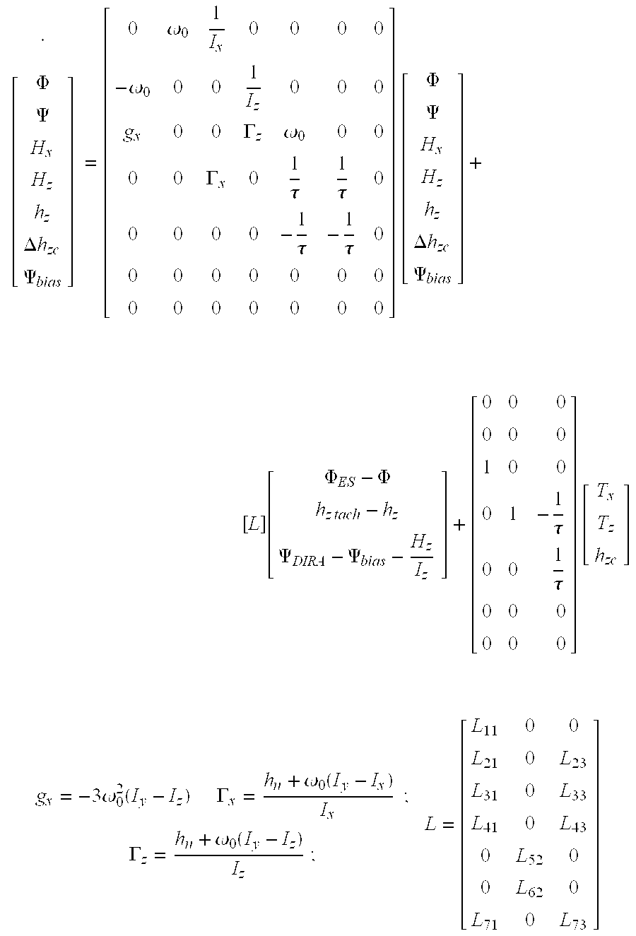
- One example of implementing the invention could be performed as follows, that is, an observer module which uses the spacecraft dynamic equations of motion corrected by the above inputs to estimate spacecraft yaw angle and momentum.
- the linearized spacecraft dynamic equations of motion used in the observer module may be stated as follows: ⁇ .
- the controller applies a set of stabilized gains to the estimates established by the spacecraft dynamic equations of motion to provide demands from the torquers and thrusters.
- the torquers maintain the spacecraft momentum, while the thrusters sit idle as their demands will be within the dead bands of the signals calling for a suitable correction and no firing commands will be issued.
- the term “deadband” can mean comparing the value of the attitude angle against a simple constant threshold
- the definition also includes more complex implementations. For example, instead of checking the value of the attitude angle, the value of the weighted sum of the attitude angle and attitude rate could be checked. Another example would replace the simple constant threshold with a more-complex threshold such as a Schmidt trigger.
Abstract
Description
| TABLE 1 |
| Observer Parameters |
| {circumflex over (Φ)} | rad | Roll estimate |
| {circumflex over (ψ)} | rad | Yaw estimate |
| Ĥx | Nms | Roll momentum estimate |
| Ĥz | Nms | Yaw momentum estimate |
| ĥz | Nms | Yaw momemtnum estimate from the wheels |
| Δĥzc | Nms | Estimate of wheel yaw momentum command offset |
| {circumflex over (Ψ)} bias | rad/sec | Estimate of DIRA yaw rate drift |
| ω0 | rad/sec | Sidereal orbit rate (˜7.29217e−5) |
| Ix | Kg-m2 | Spacecraft roll inertia |
| Iy | Kg-m2 | Spacecraft pitch inertia |
| Iz | Kg-m2 | Spacecraft yaw inertia |
| hn | Nms | Nominal pitch momentum bias from the wheel |
| speeds | ||
| τ | sec | Wheel torque time constant |
| Φ ES | rad | Unbiased roll error from the ES |
| hztach | Nms | Yaw momentum measured from the wheel speeds |
| ψ DIRA | rad/sec | Yaw rate from the DIRA |
| Tx | Nm | Roll torque form solar torque or thruster firings |
| Tz | Nm | Yaw torque from solar torque or thruster firings |
| hzc | Nms | Commanded hz output from the wheel controller |
| L | various | Reduced set of optimal steady-state Kalman gains |
Claims (10)


Priority Applications (3)
| Application Number | Priority Date | Filing Date | Title |
|---|---|---|---|
| US09/512,688 US6292722B1 (en) | 2000-02-24 | 2000-02-24 | Magnetic torquer control with thruster augmentation |
| JP2001036610A JP2001270499A (en) | 2000-02-24 | 2001-02-14 | Magnetic torquer control with thruster augmentation |
| EP01301642A EP1128247A3 (en) | 2000-02-24 | 2001-02-23 | Magnetic torquer control with thruster augmentation |
Applications Claiming Priority (1)
| Application Number | Priority Date | Filing Date | Title |
|---|---|---|---|
| US09/512,688 US6292722B1 (en) | 2000-02-24 | 2000-02-24 | Magnetic torquer control with thruster augmentation |
Publications (1)
| Publication Number | Publication Date |
|---|---|
| US6292722B1 true US6292722B1 (en) | 2001-09-18 |
Family
ID=24040120
Family Applications (1)
| Application Number | Title | Priority Date | Filing Date |
|---|---|---|---|
| US09/512,688 Expired - Lifetime US6292722B1 (en) | 2000-02-24 | 2000-02-24 | Magnetic torquer control with thruster augmentation |
Country Status (3)
| Country | Link |
|---|---|
| US (1) | US6292722B1 (en) |
| EP (1) | EP1128247A3 (en) |
| JP (1) | JP2001270499A (en) |
Cited By (19)
| Publication number | Priority date | Publication date | Assignee | Title |
|---|---|---|---|---|
| US6600976B1 (en) * | 2002-03-29 | 2003-07-29 | Lockheed Martin Corporation | Gyroless control system for zero-momentum three-axis stabilized spacecraft |
| US6695263B1 (en) | 2002-02-12 | 2004-02-24 | Lockheed Martin Corporation | System for geosynchronous spacecraft rapid earth reacquisition |
| US6702234B1 (en) | 2002-03-29 | 2004-03-09 | Lockheed Martin Corporation | Fault tolerant attitude control system for zero momentum spacecraft |
| US20040056146A1 (en) * | 2002-02-26 | 2004-03-25 | Lockheed Martin Corporation | Efficient orbit sparing system for space vehicle constellations |
| US6732977B1 (en) | 2002-02-11 | 2004-05-11 | Lockheed Martin Corporation | System for on-orbit correction of spacecraft payload pointing errors |
| US20090063885A1 (en) * | 2007-08-28 | 2009-03-05 | Arimilli Lakshminarayana B | System and Computer Program Product for Modifying an Operation of One or More Processors Executing Message Passing Interface Tasks |
| US7835826B1 (en) | 2005-12-13 | 2010-11-16 | Lockheed Martin Corporation | Attitude determination system for yaw-steering spacecraft |
| US20110153123A1 (en) * | 2009-12-22 | 2011-06-23 | The Boeing Company | Algorithm for simultaneous attitude maneuver and momentum dumping |
| US20130148250A1 (en) * | 2011-12-13 | 2013-06-13 | The Boeing Company | Multi-purpose electrical coil as a magnetic flux generator, heater or degauss coil |
| US9400502B2 (en) | 2004-09-13 | 2016-07-26 | Deka Products Limited Partnership | Control of a personal transporter based on user position |
| US9545963B2 (en) | 2002-07-12 | 2017-01-17 | DEKA Products Limited Partnership LLP | Control of a transporter based on attitude |
| US10220843B2 (en) | 2016-02-23 | 2019-03-05 | Deka Products Limited Partnership | Mobility device control system |
| USD846452S1 (en) | 2017-05-20 | 2019-04-23 | Deka Products Limited Partnership | Display housing |
| US10802495B2 (en) | 2016-04-14 | 2020-10-13 | Deka Products Limited Partnership | User control device for a transporter |
| US10908045B2 (en) | 2016-02-23 | 2021-02-02 | Deka Products Limited Partnership | Mobility device |
| US10926756B2 (en) | 2016-02-23 | 2021-02-23 | Deka Products Limited Partnership | Mobility device |
| USD915248S1 (en) | 2017-05-20 | 2021-04-06 | Deka Products Limited Partnership | Set of toggles |
| US11399995B2 (en) | 2016-02-23 | 2022-08-02 | Deka Products Limited Partnership | Mobility device |
| US11681293B2 (en) | 2018-06-07 | 2023-06-20 | Deka Products Limited Partnership | System and method for distributed utility service execution |
Families Citing this family (7)
| Publication number | Priority date | Publication date | Assignee | Title |
|---|---|---|---|---|
| US7580778B2 (en) * | 2005-06-23 | 2009-08-25 | Honeywell International Inc. | Methods and systems for controlling multi-body vehicles with fuel slosh |
| CN103941739B (en) * | 2014-04-15 | 2016-06-01 | 北京控制工程研究所 | A kind of motor-driven method of satellite attitude based on polynomial expression |
| CN104155986B (en) * | 2014-08-11 | 2015-05-20 | 北京航天自动控制研究所 | Inertial coupling characteristic-based spacecraft attitude compensation control method |
| CN104155987B (en) * | 2014-08-11 | 2015-05-20 | 北京航天自动控制研究所 | Aerodynamic coupling characteristic-based spacecraft attitude compensation control method and device |
| CN105799951B (en) * | 2014-12-31 | 2018-06-05 | 上海新跃仪表厂 | The micro- magnetic torquer of electromechanical integration and magnetic moment measurement method |
| CN108594267A (en) * | 2018-04-28 | 2018-09-28 | 中国科学院长春光学精密机械与物理研究所 | The design method of highly integrated integration microsatellite attitude control signal processing unit |
| CN110127088B (en) * | 2019-05-05 | 2020-11-20 | 北京控制工程研究所 | Double hysteresis method for unloading satellite synthetic angular momentum by using magnetic torquer |
Citations (10)
| Publication number | Priority date | Publication date | Assignee | Title |
|---|---|---|---|---|
| US4521855A (en) * | 1981-07-27 | 1985-06-04 | Ford Aerospace & Communications Corporation | Electronic on-orbit roll/yaw satellite control |
| US5123617A (en) * | 1990-03-05 | 1992-06-23 | General Electric Company | Spacecraft momentum unloading using controlled magnetic torques |
| US5130931A (en) * | 1990-07-13 | 1992-07-14 | General Electric Company | Spacecraft attitude and velocity control system |
| US5259577A (en) * | 1990-12-12 | 1993-11-09 | Aerospatiale Societe Nationale Industrielle | Attitude control system for three-axis stabilized satellite in near-equatorial orbit |
| US5597143A (en) * | 1991-09-06 | 1997-01-28 | Deutsche Aerospace Ag | Process and a device for controlling the attitude of a three-axis stabilized spinning spacecraft |
| US5610820A (en) * | 1995-03-23 | 1997-03-11 | Martin Marietta Corp. | Minimum propellant, zero momentum spacecraft attitude control system |
| US5752675A (en) * | 1995-07-03 | 1998-05-19 | Space Systems/Loral, Inc. | Thruster control of yaw without yaw measurements |
| US5787368A (en) * | 1995-11-03 | 1998-07-28 | Space Systems/Loral, Inc. | Spacecraft yaw control using only wheel speed measurements processed through a simple filter bank |
| US5788189A (en) * | 1995-06-15 | 1998-08-04 | Nec Corporation | Spacecraft and an attitude control method for a spacecraft |
| US5957410A (en) * | 1995-06-09 | 1999-09-28 | Daimler-Benz Aerospace Ag | Earth oriented satellite and process for controlling the position, nutation and spin |
Family Cites Families (2)
| Publication number | Priority date | Publication date | Assignee | Title |
|---|---|---|---|---|
| US4725024A (en) * | 1985-11-15 | 1988-02-16 | Ford Aerospace & Communications Corporation | Method for spinning up a three-axis controlled spacecraft |
| US5100084A (en) * | 1990-04-16 | 1992-03-31 | Space Systems/Loral, Inc. | Method and apparatus for inclined orbit attitude control for momentum bias spacecraft |
-
2000
- 2000-02-24 US US09/512,688 patent/US6292722B1/en not_active Expired - Lifetime
-
2001
- 2001-02-14 JP JP2001036610A patent/JP2001270499A/en active Pending
- 2001-02-23 EP EP01301642A patent/EP1128247A3/en not_active Withdrawn
Patent Citations (10)
| Publication number | Priority date | Publication date | Assignee | Title |
|---|---|---|---|---|
| US4521855A (en) * | 1981-07-27 | 1985-06-04 | Ford Aerospace & Communications Corporation | Electronic on-orbit roll/yaw satellite control |
| US5123617A (en) * | 1990-03-05 | 1992-06-23 | General Electric Company | Spacecraft momentum unloading using controlled magnetic torques |
| US5130931A (en) * | 1990-07-13 | 1992-07-14 | General Electric Company | Spacecraft attitude and velocity control system |
| US5259577A (en) * | 1990-12-12 | 1993-11-09 | Aerospatiale Societe Nationale Industrielle | Attitude control system for three-axis stabilized satellite in near-equatorial orbit |
| US5597143A (en) * | 1991-09-06 | 1997-01-28 | Deutsche Aerospace Ag | Process and a device for controlling the attitude of a three-axis stabilized spinning spacecraft |
| US5610820A (en) * | 1995-03-23 | 1997-03-11 | Martin Marietta Corp. | Minimum propellant, zero momentum spacecraft attitude control system |
| US5957410A (en) * | 1995-06-09 | 1999-09-28 | Daimler-Benz Aerospace Ag | Earth oriented satellite and process for controlling the position, nutation and spin |
| US5788189A (en) * | 1995-06-15 | 1998-08-04 | Nec Corporation | Spacecraft and an attitude control method for a spacecraft |
| US5752675A (en) * | 1995-07-03 | 1998-05-19 | Space Systems/Loral, Inc. | Thruster control of yaw without yaw measurements |
| US5787368A (en) * | 1995-11-03 | 1998-07-28 | Space Systems/Loral, Inc. | Spacecraft yaw control using only wheel speed measurements processed through a simple filter bank |
Cited By (41)
| Publication number | Priority date | Publication date | Assignee | Title |
|---|---|---|---|---|
| US9442492B2 (en) | 1999-06-04 | 2016-09-13 | Deka Products Limited Partnership | Control of a personal transporter based on user position |
| US9411336B2 (en) | 1999-06-04 | 2016-08-09 | Deka Products Limited Partnership | Control of a personal transporter based on user position |
| US9411340B2 (en) | 1999-06-04 | 2016-08-09 | Deka Products Limited Partnership | Control of a personal transporter based on user position |
| US9442491B2 (en) | 1999-06-04 | 2016-09-13 | Deka Products Limited Partnership | Control of a personal transporter based on user position |
| US10118661B2 (en) | 1999-06-04 | 2018-11-06 | Deka Products Limited Partnership | Control of a personal transporter based on user position |
| US6732977B1 (en) | 2002-02-11 | 2004-05-11 | Lockheed Martin Corporation | System for on-orbit correction of spacecraft payload pointing errors |
| US6695263B1 (en) | 2002-02-12 | 2004-02-24 | Lockheed Martin Corporation | System for geosynchronous spacecraft rapid earth reacquisition |
| US20040056146A1 (en) * | 2002-02-26 | 2004-03-25 | Lockheed Martin Corporation | Efficient orbit sparing system for space vehicle constellations |
| US7051980B2 (en) | 2002-02-26 | 2006-05-30 | Lockheed Martin Corporation | Efficient orbit sparing system for space vehicle constellations |
| US6600976B1 (en) * | 2002-03-29 | 2003-07-29 | Lockheed Martin Corporation | Gyroless control system for zero-momentum three-axis stabilized spacecraft |
| US6702234B1 (en) | 2002-03-29 | 2004-03-09 | Lockheed Martin Corporation | Fault tolerant attitude control system for zero momentum spacecraft |
| US9545963B2 (en) | 2002-07-12 | 2017-01-17 | DEKA Products Limited Partnership LLP | Control of a transporter based on attitude |
| US10227098B2 (en) | 2002-07-12 | 2019-03-12 | Deka Products Limited Partnership | Control of a transporter based on attitude |
| US11648995B2 (en) | 2002-07-12 | 2023-05-16 | Deka Products Limited Partnership | Control of a transporter based on attitude |
| US9442486B2 (en) | 2004-09-13 | 2016-09-13 | Deka Products Limited Partnership | Control of a personal transporter based on user position |
| US9411339B2 (en) | 2004-09-13 | 2016-08-09 | Deka Products Limited Partnership | Control of a personal transporter based on user position |
| US9429955B2 (en) | 2004-09-13 | 2016-08-30 | Deka Products Limited Partnership | Control of a personal transporter based on user position |
| US9400502B2 (en) | 2004-09-13 | 2016-07-26 | Deka Products Limited Partnership | Control of a personal transporter based on user position |
| US9459627B2 (en) | 2004-09-13 | 2016-10-04 | Deka Products Limited Partership | Control of a personal transporter based on user position |
| US9529365B2 (en) | 2004-09-13 | 2016-12-27 | Deka Products Limited Partnership | Control of a personal transporter based on user position |
| US9983587B2 (en) | 2004-09-13 | 2018-05-29 | Deka Products Limited Partnership | Control of a personal transporter based on user position |
| US10370052B2 (en) | 2004-09-13 | 2019-08-06 | Deka Products Limited Partnership | Control of a personal transporter based on user position |
| US7835826B1 (en) | 2005-12-13 | 2010-11-16 | Lockheed Martin Corporation | Attitude determination system for yaw-steering spacecraft |
| US20090063885A1 (en) * | 2007-08-28 | 2009-03-05 | Arimilli Lakshminarayana B | System and Computer Program Product for Modifying an Operation of One or More Processors Executing Message Passing Interface Tasks |
| US8352101B2 (en) * | 2009-12-22 | 2013-01-08 | The Boeing Company | Algorithm for simultaneous attitude maneuver and momentum dumping |
| US20110153123A1 (en) * | 2009-12-22 | 2011-06-23 | The Boeing Company | Algorithm for simultaneous attitude maneuver and momentum dumping |
| US20130148250A1 (en) * | 2011-12-13 | 2013-06-13 | The Boeing Company | Multi-purpose electrical coil as a magnetic flux generator, heater or degauss coil |
| US9114891B2 (en) * | 2011-12-13 | 2015-08-25 | The Boeing Company | Multi-purpose electrical coil as a magnetic flux generator, heater or degauss coil |
| US10752243B2 (en) | 2016-02-23 | 2020-08-25 | Deka Products Limited Partnership | Mobility device control system |
| US10908045B2 (en) | 2016-02-23 | 2021-02-02 | Deka Products Limited Partnership | Mobility device |
| US10926756B2 (en) | 2016-02-23 | 2021-02-23 | Deka Products Limited Partnership | Mobility device |
| US11399995B2 (en) | 2016-02-23 | 2022-08-02 | Deka Products Limited Partnership | Mobility device |
| US10220843B2 (en) | 2016-02-23 | 2019-03-05 | Deka Products Limited Partnership | Mobility device control system |
| US11679044B2 (en) | 2016-02-23 | 2023-06-20 | Deka Products Limited Partnership | Mobility device |
| US11794722B2 (en) | 2016-02-23 | 2023-10-24 | Deka Products Limited Partnership | Mobility device |
| US10802495B2 (en) | 2016-04-14 | 2020-10-13 | Deka Products Limited Partnership | User control device for a transporter |
| US11720115B2 (en) | 2016-04-14 | 2023-08-08 | Deka Products Limited Partnership | User control device for a transporter |
| USD876994S1 (en) | 2017-05-20 | 2020-03-03 | Deka Products Limited Partnership | Display housing |
| USD846452S1 (en) | 2017-05-20 | 2019-04-23 | Deka Products Limited Partnership | Display housing |
| USD915248S1 (en) | 2017-05-20 | 2021-04-06 | Deka Products Limited Partnership | Set of toggles |
| US11681293B2 (en) | 2018-06-07 | 2023-06-20 | Deka Products Limited Partnership | System and method for distributed utility service execution |
Also Published As
| Publication number | Publication date |
|---|---|
| JP2001270499A (en) | 2001-10-02 |
| EP1128247A3 (en) | 2002-09-18 |
| EP1128247A2 (en) | 2001-08-29 |
Similar Documents
| Publication | Publication Date | Title |
|---|---|---|
| US6292722B1 (en) | Magnetic torquer control with thruster augmentation | |
| US7988097B2 (en) | Precision attitude control system for gimbaled thruster | |
| US4537375A (en) | Method and apparatus for thruster transient control | |
| EP0769736B1 (en) | Method for inclined orbit attitude control for momentum bias spacecraft | |
| US6481672B1 (en) | Gimbaled thruster control system | |
| US5279483A (en) | Attitude control system for a three-axis stabilized satellite especially a remote sensing satellite | |
| US6296207B1 (en) | Combined stationkeeping and momentum management | |
| US8056863B2 (en) | Unified attitude control for spacecraft transfer orbit operations | |
| CA1285256C (en) | Method for spinning up a three-axis controlled spacecraft | |
| US5806804A (en) | Adaptive harmonic disturbance compensation system | |
| US5459669A (en) | Control system and method for spacecraft attitude control | |
| US6622969B2 (en) | Maneuver device for artificial satellite | |
| US6053455A (en) | Spacecraft attitude control system using low thrust thrusters | |
| JPH02157913A (en) | Active 3-axis attitude control system for | |
| US5687933A (en) | Attitude control for spacecraft with movable appendages such as solar panels | |
| US4916622A (en) | Attitude control system | |
| US6600976B1 (en) | Gyroless control system for zero-momentum three-axis stabilized spacecraft | |
| US5992799A (en) | Earth based spacecraft orbit and attitude control using a look-ahead thruster selection logic and magnetic torquers | |
| US5984237A (en) | Delta-V targeting system for three-axis controlled spacecraft | |
| WO1998016424A1 (en) | Autonomous solar torque management | |
| EP0752367A1 (en) | Thruster control of yaw without yaw measurements | |
| US6439509B1 (en) | Pre-bias scheme for roll momentum unloads on pitch momentum bias/yaw reaction wheel spacecraft | |
| Azor | Optimal roll/yaw control by thrusters |
Legal Events
| Date | Code | Title | Description |
|---|---|---|---|
| AS | Assignment |
Owner name: SPACE SYSTEMS/LORAL, INC., CALIFORNIA Free format text: ASSIGNMENT OF ASSIGNORS INTEREST;ASSIGNOR:CIELASZYK, DAVID;REEL/FRAME:010583/0508 Effective date: 20000210 |
|
| AS | Assignment |
Owner name: SPACE SYSTEMS/LORAL, INC., CALIFORNIA Free format text: ASSIGNMENT OF ASSIGNORS INTEREST;ASSIGNOR:HOLMES, THOMAS J.;REEL/FRAME:010583/0520 Effective date: 20000222 |
|
| STCF | Information on status: patent grant |
Free format text: PATENTED CASE |
|
| AS | Assignment |
Owner name: BANK OF AMERICA, N.A., AS COLLATERAL AGENT, NORTH Free format text: NOTICE OF GRANT OF SECURITY INTEREST;ASSIGNOR:SPACE SYSTEMS/LORAL, INC.;REEL/FRAME:012967/0980 Effective date: 20011221 |
|
| AS | Assignment |
Owner name: SPACE SYSTEMS/LORAL, INC., CALIFORNIA Free format text: RELEASE OF SECURITY INTEREST;ASSIGNOR:BANK OF AMERICA, N.A.;REEL/FRAME:016153/0507 Effective date: 20040802 |
|
| FPAY | Fee payment |
Year of fee payment: 4 |
|
| AS | Assignment |
Owner name: JPMORGAN CHASE BANK, N.A., AS ADMINISTRATIVE AGENT Free format text: SECURITY AGREEMENT;ASSIGNOR:SPACE SYSTEMS/LORAL, INC.;REEL/FRAME:021965/0173 Effective date: 20081016 |
|
| FPAY | Fee payment |
Year of fee payment: 8 |
|
| AS | Assignment |
Owner name: SPACE SYSTEMS/LORAL, INC., CALIFORNIA Free format text: TERMINATION AND RELEASE OF SECURITY INTEREST IN PATENT RIGHTS;ASSIGNOR:JPMORGAN CHASE BANK, N.A.;REEL/FRAME:029228/0203 Effective date: 20121102 |
|
| FPAY | Fee payment |
Year of fee payment: 12 |
|
| AS | Assignment |
Owner name: SPACE SYSTEMS/LORAL, LLC, CALIFORNIA Free format text: CHANGE OF NAME;ASSIGNOR:SPACE SYSTEMS/LORAL, INC.;REEL/FRAME:030276/0161 Effective date: 20121102 |
|
| AS | Assignment |
Owner name: ROYAL BANK OF CANADA, CANADA Free format text: SECURITY AGREEMENT;ASSIGNOR:SPACE SYSTEMS/LORAL, LLC;REEL/FRAME:030311/0419 Effective date: 20121102 |
|
| AS | Assignment |
Owner name: ROYAL BANK OF CANADA, AS THE COLLATERAL AGENT, CANADA Free format text: SECURITY INTEREST;ASSIGNORS:DIGITALGLOBE, INC.;MACDONALD, DETTWILER AND ASSOCIATES LTD.;MACDONALD, DETTWILER AND ASSOCIATES CORPORATION;AND OTHERS;REEL/FRAME:044167/0396 Effective date: 20171005 Owner name: ROYAL BANK OF CANADA, AS THE COLLATERAL AGENT, CAN Free format text: SECURITY INTEREST;ASSIGNORS:DIGITALGLOBE, INC.;MACDONALD, DETTWILER AND ASSOCIATES LTD.;MACDONALD, DETTWILER AND ASSOCIATES CORPORATION;AND OTHERS;REEL/FRAME:044167/0396 Effective date: 20171005 |
|
| AS | Assignment |
Owner name: ROYAL BANK OF CANADA, AS COLLATERAL AGENT, CANADA Free format text: AMENDED AND RESTATED U.S. PATENT AND TRADEMARK SECURITY AGREEMENT;ASSIGNOR:SPACE SYSTEMS/LORAL, LLC;REEL/FRAME:051258/0720 Effective date: 20191211 |
|
| AS | Assignment |
Owner name: WILMINGTON TRUST, NATIONAL ASSOCIATION, - AS NOTES Free format text: SECURITY AGREEMENT (NOTES);ASSIGNORS:DIGITALGLOBE, INC.;RADIANT GEOSPATIAL SOLUTIONS LLC;SPACE SYSTEMS/LORAL, LLC (F/K/A SPACE SYSTEMS/LORAL INC.);REEL/FRAME:051262/0824 Effective date: 20191211 Owner name: WILMINGTON TRUST, NATIONAL ASSOCIATION, - AS NOTES COLLATERAL AGENT, TEXAS Free format text: SECURITY AGREEMENT (NOTES);ASSIGNORS:DIGITALGLOBE, INC.;RADIANT GEOSPATIAL SOLUTIONS LLC;SPACE SYSTEMS/LORAL, LLC (F/K/A SPACE SYSTEMS/LORAL INC.);REEL/FRAME:051262/0824 Effective date: 20191211 |
|
| AS | Assignment |
Owner name: RADIANT GEOSPATIAL SOLUTIONS LLC, COLORADO Free format text: RELEASE BY SECURED PARTY;ASSIGNOR:WILMINGTON TRUST, NATIONAL ASSOCIATION;REEL/FRAME:060390/0282 Effective date: 20220614 Owner name: SPACE SYSTEMS/LORAL, LLC, CALIFORNIA Free format text: RELEASE BY SECURED PARTY;ASSIGNOR:WILMINGTON TRUST, NATIONAL ASSOCIATION;REEL/FRAME:060390/0282 Effective date: 20220614 Owner name: DIGITALGLOBE, INC., COLORADO Free format text: RELEASE BY SECURED PARTY;ASSIGNOR:WILMINGTON TRUST, NATIONAL ASSOCIATION;REEL/FRAME:060390/0282 Effective date: 20220614 |
|
| AS | Assignment |
Owner name: MAXAR SPACE LLC, CALIFORNIA Free format text: TERMINATION AND RELEASE OF SECURITY INTEREST IN PATENTS AND TRADEMARKS - RELEASE OF REEL/FRAME 044167/0396;ASSIGNOR:ROYAL BANK OF CANADA, AS AGENT;REEL/FRAME:063543/0001 Effective date: 20230503 Owner name: MAXAR INTELLIGENCE INC., COLORADO Free format text: TERMINATION AND RELEASE OF SECURITY INTEREST IN PATENTS AND TRADEMARKS - RELEASE OF REEL/FRAME 044167/0396;ASSIGNOR:ROYAL BANK OF CANADA, AS AGENT;REEL/FRAME:063543/0001 Effective date: 20230503 Owner name: MAXAR SPACE LLC, CALIFORNIA Free format text: TERMINATION AND RELEASE OF SECURITY INTEREST IN PATENTS AND TRADEMARKS - RELEASE OF REEL/FRAME 051258/0720;ASSIGNOR:ROYAL BANK OF CANADA, AS AGENT;REEL/FRAME:063542/0543 Effective date: 20230503 Owner name: MAXAR INTELLIGENCE INC., COLORADO Free format text: TERMINATION AND RELEASE OF SECURITY INTEREST IN PATENTS AND TRADEMARKS - RELEASE OF REEL/FRAME 051258/0720;ASSIGNOR:ROYAL BANK OF CANADA, AS AGENT;REEL/FRAME:063542/0543 Effective date: 20230503 |