US6151166A - Color separation element and image display device using same - Google Patents
Color separation element and image display device using same Download PDFInfo
- Publication number
- US6151166A US6151166A US09/081,629 US8162998A US6151166A US 6151166 A US6151166 A US 6151166A US 8162998 A US8162998 A US 8162998A US 6151166 A US6151166 A US 6151166A
- Authority
- US
- United States
- Prior art keywords
- diffraction gratings
- prism array
- light
- color separation
- separation element
- Prior art date
- Legal status (The legal status is an assumption and is not a legal conclusion. Google has not performed a legal analysis and makes no representation as to the accuracy of the status listed.)
- Expired - Fee Related
Links
Images
Classifications
-
- G—PHYSICS
- G02—OPTICS
- G02B—OPTICAL ELEMENTS, SYSTEMS OR APPARATUS
- G02B6/00—Light guides; Structural details of arrangements comprising light guides and other optical elements, e.g. couplings
- G02B6/0001—Light guides; Structural details of arrangements comprising light guides and other optical elements, e.g. couplings specially adapted for lighting devices or systems
- G02B6/0011—Light guides; Structural details of arrangements comprising light guides and other optical elements, e.g. couplings specially adapted for lighting devices or systems the light guides being planar or of plate-like form
- G02B6/0033—Means for improving the coupling-out of light from the light guide
- G02B6/005—Means for improving the coupling-out of light from the light guide provided by one optical element, or plurality thereof, placed on the light output side of the light guide
- G02B6/0053—Prismatic sheet or layer; Brightness enhancement element, sheet or layer
-
- G—PHYSICS
- G02—OPTICS
- G02B—OPTICAL ELEMENTS, SYSTEMS OR APPARATUS
- G02B5/00—Optical elements other than lenses
- G02B5/18—Diffraction gratings
- G02B5/1814—Diffraction gratings structurally combined with one or more further optical elements, e.g. lenses, mirrors, prisms or other diffraction gratings
-
- G—PHYSICS
- G02—OPTICS
- G02F—OPTICAL DEVICES OR ARRANGEMENTS FOR THE CONTROL OF LIGHT BY MODIFICATION OF THE OPTICAL PROPERTIES OF THE MEDIA OF THE ELEMENTS INVOLVED THEREIN; NON-LINEAR OPTICS; FREQUENCY-CHANGING OF LIGHT; OPTICAL LOGIC ELEMENTS; OPTICAL ANALOGUE/DIGITAL CONVERTERS
- G02F1/00—Devices or arrangements for the control of the intensity, colour, phase, polarisation or direction of light arriving from an independent light source, e.g. switching, gating or modulating; Non-linear optics
- G02F1/01—Devices or arrangements for the control of the intensity, colour, phase, polarisation or direction of light arriving from an independent light source, e.g. switching, gating or modulating; Non-linear optics for the control of the intensity, phase, polarisation or colour
- G02F1/13—Devices or arrangements for the control of the intensity, colour, phase, polarisation or direction of light arriving from an independent light source, e.g. switching, gating or modulating; Non-linear optics for the control of the intensity, phase, polarisation or colour based on liquid crystals, e.g. single liquid crystal display cells
- G02F1/133—Constructional arrangements; Operation of liquid crystal cells; Circuit arrangements
- G02F1/1333—Constructional arrangements; Manufacturing methods
- G02F1/1335—Structural association of cells with optical devices, e.g. polarisers or reflectors
- G02F1/1336—Illuminating devices
- G02F1/133621—Illuminating devices providing coloured light
-
- G—PHYSICS
- G02—OPTICS
- G02F—OPTICAL DEVICES OR ARRANGEMENTS FOR THE CONTROL OF LIGHT BY MODIFICATION OF THE OPTICAL PROPERTIES OF THE MEDIA OF THE ELEMENTS INVOLVED THEREIN; NON-LINEAR OPTICS; FREQUENCY-CHANGING OF LIGHT; OPTICAL LOGIC ELEMENTS; OPTICAL ANALOGUE/DIGITAL CONVERTERS
- G02F1/00—Devices or arrangements for the control of the intensity, colour, phase, polarisation or direction of light arriving from an independent light source, e.g. switching, gating or modulating; Non-linear optics
- G02F1/01—Devices or arrangements for the control of the intensity, colour, phase, polarisation or direction of light arriving from an independent light source, e.g. switching, gating or modulating; Non-linear optics for the control of the intensity, phase, polarisation or colour
- G02F1/13—Devices or arrangements for the control of the intensity, colour, phase, polarisation or direction of light arriving from an independent light source, e.g. switching, gating or modulating; Non-linear optics for the control of the intensity, phase, polarisation or colour based on liquid crystals, e.g. single liquid crystal display cells
- G02F1/133—Constructional arrangements; Operation of liquid crystal cells; Circuit arrangements
- G02F1/1333—Constructional arrangements; Manufacturing methods
- G02F1/1335—Structural association of cells with optical devices, e.g. polarisers or reflectors
- G02F1/133504—Diffusing, scattering, diffracting elements
-
- G—PHYSICS
- G02—OPTICS
- G02F—OPTICAL DEVICES OR ARRANGEMENTS FOR THE CONTROL OF LIGHT BY MODIFICATION OF THE OPTICAL PROPERTIES OF THE MEDIA OF THE ELEMENTS INVOLVED THEREIN; NON-LINEAR OPTICS; FREQUENCY-CHANGING OF LIGHT; OPTICAL LOGIC ELEMENTS; OPTICAL ANALOGUE/DIGITAL CONVERTERS
- G02F1/00—Devices or arrangements for the control of the intensity, colour, phase, polarisation or direction of light arriving from an independent light source, e.g. switching, gating or modulating; Non-linear optics
- G02F1/01—Devices or arrangements for the control of the intensity, colour, phase, polarisation or direction of light arriving from an independent light source, e.g. switching, gating or modulating; Non-linear optics for the control of the intensity, phase, polarisation or colour
- G02F1/13—Devices or arrangements for the control of the intensity, colour, phase, polarisation or direction of light arriving from an independent light source, e.g. switching, gating or modulating; Non-linear optics for the control of the intensity, phase, polarisation or colour based on liquid crystals, e.g. single liquid crystal display cells
- G02F1/133—Constructional arrangements; Operation of liquid crystal cells; Circuit arrangements
- G02F1/1333—Constructional arrangements; Manufacturing methods
- G02F1/1335—Structural association of cells with optical devices, e.g. polarisers or reflectors
- G02F1/133526—Lenses, e.g. microlenses or Fresnel lenses
-
- G—PHYSICS
- G02—OPTICS
- G02F—OPTICAL DEVICES OR ARRANGEMENTS FOR THE CONTROL OF LIGHT BY MODIFICATION OF THE OPTICAL PROPERTIES OF THE MEDIA OF THE ELEMENTS INVOLVED THEREIN; NON-LINEAR OPTICS; FREQUENCY-CHANGING OF LIGHT; OPTICAL LOGIC ELEMENTS; OPTICAL ANALOGUE/DIGITAL CONVERTERS
- G02F2201/00—Constructional arrangements not provided for in groups G02F1/00 - G02F7/00
- G02F2201/30—Constructional arrangements not provided for in groups G02F1/00 - G02F7/00 grating
- G02F2201/305—Constructional arrangements not provided for in groups G02F1/00 - G02F7/00 grating diffraction grating
Definitions
- This invention relates to color separation elements and image display devices. More particularly, this invention relates to color separation elements with high color separation capability and image display devices for displaying colors by using such an element.
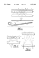
- FIG. 1 shows an example of prior art color image display device 1 comprising a surface light source (back-lighting) device 3 for emitting a beam of light which is approximately parallel to its light-emitting surface 2, a single diffraction grating 4 which serves as a color separation element, a microlens array 5 for collecting light on picture elements on a liquid crystal display panel 6 and a diffusion plate 7.
- the spectral characteristics are not sufficiently strong and the angles between the optical axes of light beams corresponding to different colors are relatively small because only one diffraction grating is used for color separation.
- a portion of the red light R passing through the microlens array 5 is made incident onto the neighboring blue and green picture elements, adversely affecting the picture quality of the formed image.
- the beams of red, green and blue light focussed by the microlens array 5 are made incident also on black matrix areas 9, and this means a loss of light or that there is less for forming the image.
- One of the methods for preventing poor picture quality for such reasons has been to make use of a microlens array 5 with a long focal length, as shown in FIG. 3, such that the focal points for the red light R, the green light G and the blue light B are sufficiently separated.
- the distance between the microlens array 5 and the liquid crystal panel 6 becomes large. This has the unfavorable effect of increasing the thickness of the image display device 1 as a whole.
- Japanese Patent Publication Tokkai 4-60538 disclosed a color image display device using dichroic mirrors but dichroic mirrors are relatively expensive and do not contribute to the miniaturization of the image display device.
- Color separation elements embodying this invention may be characterized as having a diffraction grating on both sides of a prism array such that a beam of white light passing through it will be separated into beams of different colors and the angles between the optical axes of these beams of different colors will be greater as they leave the separation element than if this beam of white light passed through only one of these diffraction gratings.
- color separation elements according to this invention have stronger spectral characteristics and can separate light of different colors by larger angles.
- the prism array and the two diffraction gratings are arranged such that the direction of diffraction by the diffraction gratings and that of refraction by the prism array are opposite to each other. It is further preferred if either or both of the diffraction gratings are formed integrally with the prism array such that the number of components can be reduced and the element becomes less bulky.
- a color image display device may be characterized not only as comprising a light source which emits an approximately parallel beam of light, a color separation element for separating this parallel beam into beams of light of different colors, a liquid crystal display panel having picture elements and a lens array for focusing the separated beams at corresponding ones of these picture elements but also wherein the color separation element is one that embodies this invention, having two diffraction gratings on both sides of a prism array as described above. Incorporating a color separation element with improved spectral characteristics, a color image display device of this invention can display color images with improved color quality.
- FIG. 1 is a schematic sectional view of a prior art image display device
- FIG. 2 is a schematic sectional view of a portion of a prior art image display device to show its problems
- FIG. 3 is a schematic sectional view of a portion of another prior art image display device to show its problem
- FIG. 4 is a schematic sectional view of an image display device with a color separation element embodying this invention.
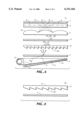
- FIGS. 5, 6 and 7 are schematic sectional views of other color separation elements embodying this invention.
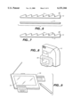
- FIG. 8 is a diagonal view of a video camera provided with a color image display device embodying this invention.
- FIG. 9 is a diagonal view of a portable work station with a color image display device embodying this invention.
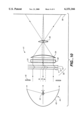
- FIG. 10 is a schematic sectional view of a liquid crystal image projector incorporating a color separation element embodying this invention shown in FIG. 4.
- FIG. 4 shows an image display device 11 according to one embodiment of this invention, comprising a surface light source device 3, a color separation element which includes a first diffraction grating 4, a prism array 12 and a second diffraction grating 13, a microlens array 5, a liquid crystal display panel 6 and a diffusion plate 7.
- the surface light source device 3 is formed by setting a light source 15 adjacent an end surface 17 of a light-conducting plate 14 made of a transparent resin material with a high index of refraction such as polycarbonate resins or methacrylic resins and placing a reflector sheet 16 on the lower surface of the light-conducting plate 14.
- a beam of white light W is emitted from the light source 15, it enters the interior of the light-conducting plate 14 through its end surface 17 and propagates inside the light-conducting plate 14 by repeatedly undergoing total reflections.
- the light which thus propagates inside the light-conducting plate 14 is emitted from its light-emitting surface 2 when the angle of incidence, as the light hits the light-emitting surface 2 from inside, becomes smaller than the critical angle for the total reflection.
- the portion of light which is emitted out of the light-conducting plate 14 through its lower surface is reflected back by the reflector sheet 16 and enters the interior of the light-conducting plate 14 again.
- the incident white light W from the light source 15 into the interior of the light-conducting plate 14 is projected out as an approximately parallel beam nearly uniformly from all parts of the light-emitting surface 2 of the light-conducting plate 14.
- the approximately parallel beam of white light W, thus projected out of the light-emitting surface 2 of the light-conducting plate 14 is diffracted first by the first diffraction grating 4 disposed opposite the light-emitting surface 2.
- the light-conducting plate 14 and the first diffraction grating 4 are designed such that the diffracted beams of the first order by the first diffraction grating 4 will thereafter propagate approximately perpendicularly to the grating 4. Since the angle of diffraction depends on the wavelength of the light, the first-order diffracted beams of red light R, green light G and blue light B are separated and travel in different directions.
- the first-order diffracted beams of light pass through the prism array 12 and are each refracted by a corresponding one of its prisms 12a. Since the angle of refraction of the light passing through the prism array 12 depends also on the wavelength of the light, the red light R, the green light G and the blue light B are refracted by different angles.
- the prism array 12 is arranged in such a way that the angles between the optical axes of the red light R, the green light G and the blue light will become even larger after they pass through the prism array 12.
- the pattern angle of the prism array 12 (the bottom angle of each prism 12a) is designed such that light of each color will be directed approximately parallel to the prism array 12.
- the prism array 12 and the second diffraction grating 13 the focal points of these light beams with different colors can be sufficiently separated and the spectral characteristic can be improved although the distance between the microlens array 5 and the liquid crystal display panel 6 is not increased. Thus, images can be displayed with improved color reproduction. Moreover, since the light beams are less likely to be screened by the black matrix areas 9, the loss in the quantity of light can be reduced.
- the prism array 12 has the additional function of adjusting the direction of light incident on the second diffraction grating 13. For this reason, it is so arranged that the angular deflection by the prism array 12 should be opposite to that by the first and the second diffraction gratings 4 and 13.
- FIG. 5 shows another color separation element 21 according to this invention which is different from the color separation element incorporated in the image display device of FIG. 4 wherein the second grating 13 is integrally formed on the surface of the prism array 12 opposite from its patterned surface.
- the first diffraction grating 4 is disposed opposite the patterned surface of the prism array 12.
- FIG. 6 shows still another color separation element 22 according to this invention characterized as having the second diffraction grating 13 formed integrally on the patterned surface of the prism array 12, the first diffraction grating being disposed opposite the other surface of the prism array 12.
- FIG. 7 shows still another color separation element 23 according to this invention characterized as having both the second diffraction grating 13 and the first diffraction grating 4 formed integrally respectively on the patterned surface and the opposite surface of the prism array 12.
- the diffraction grating 13 and the prism array 12 are thus integrated, not only is the spectral characteristic of the color separation element improved but the element can also be made thinner with the number of components thereby reduced.
- an image display device can be made smaller, say, than if use is made of dichroic mirrors for color separation.
- FIG. 8 shows a video camera 31 provided with a color image display device 32 embodying this invention on which the picture being taken may be displayed or a recorded image may be reproduced.
- FIG. 9 shows a portable work station 33 with an image display device 34 embodying this invention.
- FIG. 10 shows an example of liquid crystal color image projector 41 incorporating a color separation element embodying this invention.
- Numeral 44 indicates a back-light source having a lamp 42 and a reflector 43 with a paraboloidal surface placed behind it. Light emitted from the lamp 42 is reflected by this reflector 43 to form an approximately parallel beam of light which is made incident through a slit 45 onto a color separation element 50 embodying this invention.
- the color separation element 50 may, for example, be of the kind shown in FIG. 4 having a first diffraction grating 4, a prism array 12 and a second diffraction grating 13. An image formed through a microlens array 51 on a liquid crystal display panel 52 is thereby projected through a field lens 54 and a projection lens 55 onto a screen 56.
Abstract
Description
Claims (16)
Applications Claiming Priority (2)
| Application Number | Priority Date | Filing Date | Title |
|---|---|---|---|
| JP9-150413 | 1997-05-22 | ||
| JP9150413A JPH10319217A (en) | 1997-05-22 | 1997-05-22 | Color separating element and image display device |
Publications (1)
| Publication Number | Publication Date |
|---|---|
| US6151166A true US6151166A (en) | 2000-11-21 |
Family
ID=15496408
Family Applications (1)
| Application Number | Title | Priority Date | Filing Date |
|---|---|---|---|
| US09/081,629 Expired - Fee Related US6151166A (en) | 1997-05-22 | 1998-05-19 | Color separation element and image display device using same |
Country Status (2)
| Country | Link |
|---|---|
| US (1) | US6151166A (en) |
| JP (1) | JPH10319217A (en) |
Cited By (45)
| Publication number | Priority date | Publication date | Assignee | Title |
|---|---|---|---|---|
| US20020003961A1 (en) * | 2000-05-25 | 2002-01-10 | Toshinobu Yamaguchi | Image-capture apparatus including light-guiding element having inclined surface |
| US6356389B1 (en) * | 1999-11-12 | 2002-03-12 | Reflexite Corporation | Subwavelength optical microstructure light collimating films |
| US20030095399A1 (en) * | 2001-11-16 | 2003-05-22 | Christopher Grenda | Light emitting diode light bar |
| US6570710B1 (en) | 1999-11-12 | 2003-05-27 | Reflexite Corporation | Subwavelength optical microstructure light collimating films |
| US6621520B1 (en) * | 1998-06-09 | 2003-09-16 | Pentax Corporation | Display unit of digital camera |
| US6642975B2 (en) * | 2000-10-11 | 2003-11-04 | Fuji Photo Film Co., Ltd. | Transfer apparatus |
| WO2004015489A1 (en) * | 2002-08-07 | 2004-02-19 | Koninklijke Philips Electronics N.V. | Display device with light guiding substrate |
| US6759965B1 (en) * | 1999-05-28 | 2004-07-06 | Oy Ics Intelligent Control Systems Ltd | Light indicator |
| US6773126B1 (en) | 1999-05-28 | 2004-08-10 | Oy Modilis Ltd. | Light panel with improved diffraction |
| US20040252867A1 (en) * | 2000-01-05 | 2004-12-16 | Je-Hsiung Lan | Biometric sensor |
| US20050041174A1 (en) * | 2003-08-19 | 2005-02-24 | International Business Machines Corporation | Color filterless display device, optical element, and manufacture |
| US20050195588A1 (en) * | 2004-03-08 | 2005-09-08 | Sung-Yong Kang | Optical member, backlight assembly and display device having the same |
| US20050259939A1 (en) * | 2004-04-30 | 2005-11-24 | Kari Rinko | Ultra thin lighting element |
| US20060001970A1 (en) * | 2004-07-02 | 2006-01-05 | Zoltan Facius | Optical arrangement for pre-processing primary illumination light |
| US20060187365A1 (en) * | 2005-02-18 | 2006-08-24 | Infocus Corporation | Optical assembly to provide complementary illumination of subpixels of a light valve pixel |
| US20060203517A1 (en) * | 2002-06-26 | 2006-09-14 | Sung-Yong Kang | Backlight assembly and liquid crystal display apparatus having the same |
| US20060239629A1 (en) * | 2005-04-20 | 2006-10-26 | Jun Qi | Elliptical diffusers used in displays |
| US20070040950A1 (en) * | 2005-08-16 | 2007-02-22 | Samsung Electronics Co., Ltd. | Color-filterless LCD |
| EP1757976A1 (en) * | 2005-08-26 | 2007-02-28 | Samsung Electronics Co., Ltd. | Direct light type backlight unit and liquid crystal display |
| US20070086086A1 (en) * | 2006-01-13 | 2007-04-19 | Optical Research Associates | Light enhancing structures with three or more arrays of elongate features |
| WO2007105895A1 (en) * | 2006-03-14 | 2007-09-20 | Lgs Corporation Ltd | Surface light source device for lcd |
| US20070258247A1 (en) * | 2006-05-02 | 2007-11-08 | Samsung Electronics Co., Ltd. | Light-emitting module capable of increasing dispersion diameter |
| CN100392490C (en) * | 2003-12-05 | 2008-06-04 | 阿尔卑斯电气株式会社 | Prism sheet, illuminating device, surface emitting device, and liquid crystal display device |
| US20080253147A1 (en) * | 2007-04-12 | 2008-10-16 | Samsung Electronics Co., Ltd. | Backlight unit having improved chromatic dispersion |
| CN100430797C (en) * | 2005-09-26 | 2008-11-05 | 三星电子株式会社 | Direct light type backlight unit and color filterless liquid crystal display apparatus employing the same |
| US20080297699A1 (en) * | 2007-05-31 | 2008-12-04 | Hitachi Maxell, Ltd. | Optical adjusting member and illumination device and liquid crystal display device including the same |
| US20090015756A1 (en) * | 2007-07-10 | 2009-01-15 | Au Optronics Corp. | Color-filterless liquid crystal display device |
| US20090225533A1 (en) * | 2008-03-10 | 2009-09-10 | Victor Company Of Japan, Ltd. | Optical unit, backlight device, liquid crystal module and liquid crystal display apparatus |
| US7674028B2 (en) | 2006-01-13 | 2010-03-09 | Avery Dennison Corporation | Light enhancing structures with multiple arrays of elongate features of varying characteristics |
| EP2172700A1 (en) | 2008-10-06 | 2010-04-07 | Samsung Electronics Co., Ltd. | Back light unit and image display device using the same |
| US20100103347A1 (en) * | 2005-08-04 | 2010-04-29 | Kiminori Mizuuchi | Display and illuminator |
| EP2230550A1 (en) | 2009-03-18 | 2010-09-22 | Victor Company of Japan Ltd. | Optical unit, backlight device, liquid crystal module and liquid crystal display apparatus |
| CN101852875A (en) * | 2009-04-03 | 2010-10-06 | 鸿富锦精密工业(深圳)有限公司 | Fresnel lens |
| US7866871B2 (en) | 2006-01-13 | 2011-01-11 | Avery Dennison Corporation | Light enhancing structures with a plurality of arrays of elongate features |
| US20110157521A1 (en) * | 2008-07-22 | 2011-06-30 | Hitachi Maxell, Ltd. | Liquid crystal display |
| US20110187964A1 (en) * | 2010-02-04 | 2011-08-04 | Chimei Innolux Corporation | Liquid crystal panel module, backlight module and liquid crystal display |
| US20110216266A1 (en) * | 2010-03-02 | 2011-09-08 | Microsoft Corporation | Wedge backlight with diffraction grating |
| CN101315433B (en) * | 2007-05-31 | 2012-05-23 | 日立麦克赛尔株式会社 | Optical adjusting member and illumination device and liquid crystal display device including the same |
| TWI381218B (en) * | 2008-08-08 | 2013-01-01 | Ind Tech Res Inst | System for optical color division and displaying apparatus in application |
| US8619363B1 (en) | 2007-11-06 | 2013-12-31 | Fusion Optix, Inc. | Light redirecting element comprising a forward diffracting region and a scattering region |
| US20140043564A1 (en) * | 2009-04-13 | 2014-02-13 | JVC Kenwood Corporation | Backlight device |
| US20160018066A1 (en) * | 2014-07-18 | 2016-01-21 | Intel Corporation | Lighting arrangement |
| WO2017118063A1 (en) * | 2016-01-08 | 2017-07-13 | 京东方科技集团股份有限公司 | Display substrate, display panel, and display device |
| US20180299732A1 (en) * | 2016-01-08 | 2018-10-18 | Boe Technology Group Co., Ltd. | Light source color seperation device and display device |
| US11272169B2 (en) * | 2017-11-01 | 2022-03-08 | Boe Technology Group Co., Ltd. | Viewpoint controllable three-dimensional image display apparatus and method for displaying three-dimensional image |
Families Citing this family (8)
| Publication number | Priority date | Publication date | Assignee | Title |
|---|---|---|---|---|
| JP2000241812A (en) * | 1999-02-22 | 2000-09-08 | Internatl Business Mach Corp <Ibm> | Transmission type liquid crystal display device |
| JP3457591B2 (en) | 1999-10-08 | 2003-10-20 | インターナショナル・ビジネス・マシーンズ・コーポレーション | Liquid crystal display |
| KR100673990B1 (en) * | 2005-05-24 | 2007-01-25 | 엘지전자 주식회사 | Backlight unit, liquid crystal display device and reverse prism sheet employed in the same |
| KR100750168B1 (en) | 2006-03-06 | 2007-08-21 | 삼성전자주식회사 | Color-filterless lcd |
| JP4945414B2 (en) * | 2007-11-30 | 2012-06-06 | 日立マクセル株式会社 | Optical adjusting member, and illumination device and liquid crystal display device including the same |
| JP2011154078A (en) * | 2010-01-26 | 2011-08-11 | Hitachi Displays Ltd | Liquid crystal display device |
| CN105954923B (en) * | 2016-07-15 | 2019-07-23 | 京东方科技集团股份有限公司 | Display base plate and preparation method thereof, display panel and display device |
| JP7203676B2 (en) * | 2019-04-16 | 2023-01-13 | 株式会社ジャパンディスプレイ | Display device |
Citations (2)
| Publication number | Priority date | Publication date | Assignee | Title |
|---|---|---|---|---|
| US5528720A (en) * | 1992-03-23 | 1996-06-18 | Minnesota Mining And Manufacturing Co. | Tapered multilayer luminaire devices |
| US5831765A (en) * | 1995-05-24 | 1998-11-03 | Sanyo Electric Co., Ltd. | Two-dimensional/three-dimensional compatible type image display |
-
1997
- 1997-05-22 JP JP9150413A patent/JPH10319217A/en active Pending
-
1998
- 1998-05-19 US US09/081,629 patent/US6151166A/en not_active Expired - Fee Related
Patent Citations (2)
| Publication number | Priority date | Publication date | Assignee | Title |
|---|---|---|---|---|
| US5528720A (en) * | 1992-03-23 | 1996-06-18 | Minnesota Mining And Manufacturing Co. | Tapered multilayer luminaire devices |
| US5831765A (en) * | 1995-05-24 | 1998-11-03 | Sanyo Electric Co., Ltd. | Two-dimensional/three-dimensional compatible type image display |
Cited By (87)
| Publication number | Priority date | Publication date | Assignee | Title |
|---|---|---|---|---|
| US6621520B1 (en) * | 1998-06-09 | 2003-09-16 | Pentax Corporation | Display unit of digital camera |
| US6759965B1 (en) * | 1999-05-28 | 2004-07-06 | Oy Ics Intelligent Control Systems Ltd | Light indicator |
| US6773126B1 (en) | 1999-05-28 | 2004-08-10 | Oy Modilis Ltd. | Light panel with improved diffraction |
| US6570710B1 (en) | 1999-11-12 | 2003-05-27 | Reflexite Corporation | Subwavelength optical microstructure light collimating films |
| US6356389B1 (en) * | 1999-11-12 | 2002-03-12 | Reflexite Corporation | Subwavelength optical microstructure light collimating films |
| US20040027676A1 (en) * | 1999-11-12 | 2004-02-12 | Reflexite Corporation | Subwavelength optical microstructure light-redirecting films |
| US6891677B2 (en) * | 1999-11-12 | 2005-05-10 | Reflexite Corporation | Subwavelength optical microstructure light-redirecting films |
| US20040252867A1 (en) * | 2000-01-05 | 2004-12-16 | Je-Hsiung Lan | Biometric sensor |
| US7570302B2 (en) | 2000-05-25 | 2009-08-04 | Canon Kabushiki Kaisha | Image-capture apparatus including light-guiding element having inclined surface |
| US6992724B2 (en) * | 2000-05-25 | 2006-01-31 | Canon Kabushiki Kaisha | Image-capture apparatus including light-guiding element having inclined surface |
| US20020003961A1 (en) * | 2000-05-25 | 2002-01-10 | Toshinobu Yamaguchi | Image-capture apparatus including light-guiding element having inclined surface |
| US20060044443A1 (en) * | 2000-05-25 | 2006-03-02 | Canon Kabushiki Kaisha | Image-capture apparatus including light-guiding element having inclined surface |
| US6642975B2 (en) * | 2000-10-11 | 2003-11-04 | Fuji Photo Film Co., Ltd. | Transfer apparatus |
| US20030095399A1 (en) * | 2001-11-16 | 2003-05-22 | Christopher Grenda | Light emitting diode light bar |
| US6948840B2 (en) | 2001-11-16 | 2005-09-27 | Everbrite, Llc | Light emitting diode light bar |
| US20060203517A1 (en) * | 2002-06-26 | 2006-09-14 | Sung-Yong Kang | Backlight assembly and liquid crystal display apparatus having the same |
| WO2004015489A1 (en) * | 2002-08-07 | 2004-02-19 | Koninklijke Philips Electronics N.V. | Display device with light guiding substrate |
| US7164454B2 (en) * | 2003-08-19 | 2007-01-16 | International Business Machines Incorporated | Color filterless display device, optical element, and manufacture |
| US8767139B2 (en) | 2003-08-19 | 2014-07-01 | International Business Machines Corporation | Color filterless display device, optical element, and manufacture |
| US20050041174A1 (en) * | 2003-08-19 | 2005-02-24 | International Business Machines Corporation | Color filterless display device, optical element, and manufacture |
| US20070139582A1 (en) * | 2003-08-19 | 2007-06-21 | International Business Machine Corporation | Color filterless display device, optical element, and manufacture |
| US8879016B2 (en) | 2003-08-19 | 2014-11-04 | International Business Machines Corporation | Color filterless display device, optical element, and manufacture |
| US7936412B2 (en) | 2003-08-19 | 2011-05-03 | International Business Machines Corporation | Color filterless display device, optical element, and manufacture |
| CN100392490C (en) * | 2003-12-05 | 2008-06-04 | 阿尔卑斯电气株式会社 | Prism sheet, illuminating device, surface emitting device, and liquid crystal display device |
| US20050195588A1 (en) * | 2004-03-08 | 2005-09-08 | Sung-Yong Kang | Optical member, backlight assembly and display device having the same |
| US8425102B2 (en) | 2004-04-30 | 2013-04-23 | Modilis Holdings Llc | Ultrathin lighting element |
| US8864359B1 (en) | 2004-04-30 | 2014-10-21 | Modilis Holdings Llc | Ultrathin lighting element |
| US20050259939A1 (en) * | 2004-04-30 | 2005-11-24 | Kari Rinko | Ultra thin lighting element |
| US7565054B2 (en) | 2004-04-30 | 2009-07-21 | Oy Modilis Ltd. | Ultra thin lighting element |
| US10422938B1 (en) | 2004-04-30 | 2019-09-24 | Modilis Holdings Llc | Ultrathin lighting element |
| US7359119B2 (en) | 2004-07-02 | 2008-04-15 | Sony Deutschland Gmbh | Optical arrangement for pre-processing primary illumination light |
| US20060001970A1 (en) * | 2004-07-02 | 2006-01-05 | Zoltan Facius | Optical arrangement for pre-processing primary illumination light |
| US20060187415A1 (en) * | 2005-02-18 | 2006-08-24 | Slobodin David E | Subpixels of a light valve pixel having characteristics adapted to complement light within a range of wavelengths |
| US7554623B2 (en) * | 2005-02-18 | 2009-06-30 | Infocus Corporation | Optical assembly to provide complementary illumination of subpixels of a light valve pixel |
| US7847868B2 (en) | 2005-02-18 | 2010-12-07 | Seiko Epson Corporation | Subpixels of a light valve pixel having characteristics adapted to complement light within a range of wavelengths |
| US20060187365A1 (en) * | 2005-02-18 | 2006-08-24 | Infocus Corporation | Optical assembly to provide complementary illumination of subpixels of a light valve pixel |
| WO2006118784A2 (en) * | 2005-04-20 | 2006-11-09 | Wavefront Technology, Inc. | Elliptical diffusers used in displays |
| US7430358B2 (en) * | 2005-04-20 | 2008-09-30 | Wavefront Technology, Inc. | Elliptical diffusers used in displays |
| US20060239629A1 (en) * | 2005-04-20 | 2006-10-26 | Jun Qi | Elliptical diffusers used in displays |
| WO2006118784A3 (en) * | 2005-04-20 | 2007-11-08 | Wavefront Technology Inc | Elliptical diffusers used in displays |
| US8089581B2 (en) * | 2005-08-04 | 2012-01-03 | Panasonic Corporation | Display and illuminator |
| US20100103347A1 (en) * | 2005-08-04 | 2010-04-29 | Kiminori Mizuuchi | Display and illuminator |
| US20070040950A1 (en) * | 2005-08-16 | 2007-02-22 | Samsung Electronics Co., Ltd. | Color-filterless LCD |
| US7580083B2 (en) * | 2005-08-16 | 2009-08-25 | Samsung Electronics Co., Ltd. | Color-filterless LCD |
| NL1032332C2 (en) * | 2005-08-16 | 2010-08-25 | Samsung Electronics Co Ltd | COLOR FILTERLESS LCD DEVICE. |
| US7659951B2 (en) | 2005-08-26 | 2010-02-09 | Samsung Electronics Co., Ltd. | Direct light type backlight unit and liquid crystal display |
| EP1757976A1 (en) * | 2005-08-26 | 2007-02-28 | Samsung Electronics Co., Ltd. | Direct light type backlight unit and liquid crystal display |
| CN100430797C (en) * | 2005-09-26 | 2008-11-05 | 三星电子株式会社 | Direct light type backlight unit and color filterless liquid crystal display apparatus employing the same |
| US20070086086A1 (en) * | 2006-01-13 | 2007-04-19 | Optical Research Associates | Light enhancing structures with three or more arrays of elongate features |
| US7366393B2 (en) * | 2006-01-13 | 2008-04-29 | Optical Research Associates | Light enhancing structures with three or more arrays of elongate features |
| US7866871B2 (en) | 2006-01-13 | 2011-01-11 | Avery Dennison Corporation | Light enhancing structures with a plurality of arrays of elongate features |
| US7674028B2 (en) | 2006-01-13 | 2010-03-09 | Avery Dennison Corporation | Light enhancing structures with multiple arrays of elongate features of varying characteristics |
| US9075177B2 (en) | 2006-01-13 | 2015-07-07 | Avery Dennison Corporation | Light enhancing structures with a plurality of arrays of elongate features |
| WO2007105895A1 (en) * | 2006-03-14 | 2007-09-20 | Lgs Corporation Ltd | Surface light source device for lcd |
| US20070258247A1 (en) * | 2006-05-02 | 2007-11-08 | Samsung Electronics Co., Ltd. | Light-emitting module capable of increasing dispersion diameter |
| US20080253147A1 (en) * | 2007-04-12 | 2008-10-16 | Samsung Electronics Co., Ltd. | Backlight unit having improved chromatic dispersion |
| US7658531B2 (en) * | 2007-04-12 | 2010-02-09 | Samsung Electronics Co., Ltd. | Backlight unit having improved chromatic dispersion |
| US20080297699A1 (en) * | 2007-05-31 | 2008-12-04 | Hitachi Maxell, Ltd. | Optical adjusting member and illumination device and liquid crystal display device including the same |
| US8368839B2 (en) * | 2007-05-31 | 2013-02-05 | Hitachi Maxell, Ltd. | Optical adjusting member and illumination device and liquid crystal display device including the same |
| CN101315433B (en) * | 2007-05-31 | 2012-05-23 | 日立麦克赛尔株式会社 | Optical adjusting member and illumination device and liquid crystal display device including the same |
| US20090015756A1 (en) * | 2007-07-10 | 2009-01-15 | Au Optronics Corp. | Color-filterless liquid crystal display device |
| US7583332B2 (en) | 2007-07-10 | 2009-09-01 | Au Optronics Corp. | Color-filterless liquid crystal display device |
| US8619363B1 (en) | 2007-11-06 | 2013-12-31 | Fusion Optix, Inc. | Light redirecting element comprising a forward diffracting region and a scattering region |
| US20090225533A1 (en) * | 2008-03-10 | 2009-09-10 | Victor Company Of Japan, Ltd. | Optical unit, backlight device, liquid crystal module and liquid crystal display apparatus |
| EP2101212A1 (en) * | 2008-03-10 | 2009-09-16 | Victor Company of Japan Ltd. | Optical unit, backlight device, liquid crystal module and liquid crystal display apparatus |
| US7819543B2 (en) | 2008-03-10 | 2010-10-26 | Victor Company Of Japan, Ltd. | Optical unit, backlight device, liquid crystal module and liquid crystal display apparatus |
| US20110157521A1 (en) * | 2008-07-22 | 2011-06-30 | Hitachi Maxell, Ltd. | Liquid crystal display |
| TWI381218B (en) * | 2008-08-08 | 2013-01-01 | Ind Tech Res Inst | System for optical color division and displaying apparatus in application |
| EP2172700A1 (en) | 2008-10-06 | 2010-04-07 | Samsung Electronics Co., Ltd. | Back light unit and image display device using the same |
| US20100085733A1 (en) * | 2008-10-06 | 2010-04-08 | Samsung Electronics Co., Ltd. | Back light unit and image display device using the same |
| US20100238378A1 (en) * | 2009-03-18 | 2010-09-23 | Victor Company Of Japan, Ltd. | Optical unit, backlight device, liquid crystal module and liquid crystal display apparatus |
| US8294847B2 (en) | 2009-03-18 | 2012-10-23 | Victor Company Of Japan, Ltd. | Optical unit, backlight device, liquid crystal module and liquid crystal display apparatus |
| EP2230550A1 (en) | 2009-03-18 | 2010-09-22 | Victor Company of Japan Ltd. | Optical unit, backlight device, liquid crystal module and liquid crystal display apparatus |
| CN101852875B (en) * | 2009-04-03 | 2013-03-20 | 鸿富锦精密工业(深圳)有限公司 | Fresnel lens |
| CN101852875A (en) * | 2009-04-03 | 2010-10-06 | 鸿富锦精密工业(深圳)有限公司 | Fresnel lens |
| US9389357B2 (en) | 2009-04-13 | 2016-07-12 | JVC Kenwood Corporation | Backlight device |
| US20140043564A1 (en) * | 2009-04-13 | 2014-02-13 | JVC Kenwood Corporation | Backlight device |
| US8807818B2 (en) * | 2009-04-13 | 2014-08-19 | JVC Kenwood Corporation | Backlight device |
| US8736787B2 (en) * | 2010-02-04 | 2014-05-27 | Chimei Innolux Corporation | Liquid crystal panel module, backlight module and liquid crystal display |
| US20110187964A1 (en) * | 2010-02-04 | 2011-08-04 | Chimei Innolux Corporation | Liquid crystal panel module, backlight module and liquid crystal display |
| US20110216266A1 (en) * | 2010-03-02 | 2011-09-08 | Microsoft Corporation | Wedge backlight with diffraction grating |
| US20160018066A1 (en) * | 2014-07-18 | 2016-01-21 | Intel Corporation | Lighting arrangement |
| US10471467B2 (en) * | 2014-07-18 | 2019-11-12 | North Inc. | Lighting arrangement |
| WO2017118063A1 (en) * | 2016-01-08 | 2017-07-13 | 京东方科技集团股份有限公司 | Display substrate, display panel, and display device |
| CN106959541A (en) * | 2016-01-08 | 2017-07-18 | 京东方科技集团股份有限公司 | Display base plate, display panel and display device |
| US20180299732A1 (en) * | 2016-01-08 | 2018-10-18 | Boe Technology Group Co., Ltd. | Light source color seperation device and display device |
| US11272169B2 (en) * | 2017-11-01 | 2022-03-08 | Boe Technology Group Co., Ltd. | Viewpoint controllable three-dimensional image display apparatus and method for displaying three-dimensional image |
Also Published As
| Publication number | Publication date |
|---|---|
| JPH10319217A (en) | 1998-12-04 |
Similar Documents
| Publication | Publication Date | Title |
|---|---|---|
| US6151166A (en) | Color separation element and image display device using same | |
| US6474827B2 (en) | Image display apparatus | |
| USRE39243E1 (en) | Optical element, polarization illumination device, and projector | |
| US6219111B1 (en) | Projection-type liquid crystal display apparatus | |
| US6685322B2 (en) | Optical system and projection-type image display device | |
| US20020126390A1 (en) | Lens array substrate and image display device | |
| US6680762B2 (en) | Projection liquid crystal display apparatus wherein overall focal point of the lens is shifted to increase effective aperture ratio | |
| US6607280B2 (en) | Projection apparatus | |
| JPH08334623A (en) | Polarization dividing device | |
| US6315417B1 (en) | Projector | |
| US6457828B1 (en) | Display optical apparatus | |
| JP3746905B2 (en) | Image projector | |
| JPH095699A (en) | Illuminator of liquid crystal screen | |
| KR100501789B1 (en) | Compact lighting device | |
| EP0911676B1 (en) | Liquid crystal panel unit and liquid crystal projector using the same | |
| US6398365B1 (en) | Image projection display apparatus | |
| JP4055237B2 (en) | Image display device | |
| US6049410A (en) | Structure of spatial light modulator and lighting system therefor | |
| JPH11295652A (en) | Image display device and projection image display device using the same | |
| JP3011228B2 (en) | Color separation optics | |
| JPS6330835A (en) | Transmission type screen | |
| US6088076A (en) | Liquid crystal display apparatus using holographic optical element | |
| AU764831B2 (en) | Projection display device | |
| JP2001103400A (en) | Projection type display device | |
| KR20000031113A (en) | Optical system for projector of three plate-typed digital micro mirror |
Legal Events
| Date | Code | Title | Description |
|---|---|---|---|
| AS | Assignment |
Owner name: OMRON CORPORATION, JAPAN Free format text: ASSIGNMENT OF ASSIGNORS INTEREST;ASSIGNORS:MATSUSHITA, TOMOHIKO;SHINOHARA, MASAYUKI;AOYAMA, SHIGERU;REEL/FRAME:009320/0318 Effective date: 19980707 |
|
| FPAY | Fee payment |
Year of fee payment: 4 |
|
| FEPP | Fee payment procedure |
Free format text: PAYOR NUMBER ASSIGNED (ORIGINAL EVENT CODE: ASPN); ENTITY STATUS OF PATENT OWNER: LARGE ENTITY |
|
| FPAY | Fee payment |
Year of fee payment: 8 |
|
| REMI | Maintenance fee reminder mailed | ||
| LAPS | Lapse for failure to pay maintenance fees | ||
| STCH | Information on status: patent discontinuation |
Free format text: PATENT EXPIRED DUE TO NONPAYMENT OF MAINTENANCE FEES UNDER 37 CFR 1.362 |
|
| FP | Lapsed due to failure to pay maintenance fee |
Effective date: 20121121 |