US6147807A - High brightness see-through head-mounted display - Google Patents
High brightness see-through head-mounted display Download PDFInfo
- Publication number
- US6147807A US6147807A US09/304,361 US30436199A US6147807A US 6147807 A US6147807 A US 6147807A US 30436199 A US30436199 A US 30436199A US 6147807 A US6147807 A US 6147807A
- Authority
- US
- United States
- Prior art keywords
- image
- head mounted
- mounted display
- prism
- display
- Prior art date
- Legal status (The legal status is an assumption and is not a legal conclusion. Google has not performed a legal analysis and makes no representation as to the accuracy of the status listed.)
- Expired - Lifetime
Links
Images
Classifications
-
- G—PHYSICS
- G02—OPTICS
- G02B—OPTICAL ELEMENTS, SYSTEMS OR APPARATUS
- G02B27/00—Optical systems or apparatus not provided for by any of the groups G02B1/00 - G02B26/00, G02B30/00
- G02B27/01—Head-up displays
- G02B27/017—Head mounted
- G02B27/0172—Head mounted characterised by optical features
Definitions
- Head mounted displays which generally allow for the simultaneous viewing of visual information and/or images generated by a computer or other source with and/or superimposed on a direct viewing of an external scene are well known. Such head mounted displays find utility in many areas, such as training, machine control, or entertainment. Such systems have found particular utility in military applications where information must be supplied to vehicle operators and weapons controllers. Aircraft pilots find such systems useful to furnish information relating to aircraft operation, weather radar presentations, maps, weapons aiming, and other such information.
- the visual information or visual images are superimposed on an optical combiner mounted on the head gear, sometimes a helmet visor, in view of the eye of the wearer, i.e., the observer's line of sight.
- These visual images may be derived from a variety of display sources including cathode ray tubes, fiber optic displays, flat panel liquid crystal or electroluminescent devices, some including image enhancers, and even photographic projectors operating with an appropriate optical relay system, all of which may supply the observer with visual information.
- display sources including cathode ray tubes, fiber optic displays, flat panel liquid crystal or electroluminescent devices, some including image enhancers, and even photographic projectors operating with an appropriate optical relay system, all of which may supply the observer with visual information.
- the demand for smaller systems on the head with lighter weight requires use of the new micro miniature displays, measuring less than 1 inch across the diagonal.
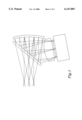
- FIG. 1 shows a current optical relay system. It is a lightweight system utilizing flat panel displays. However, there is a great loss in the throughput from the flat panel display to the eye, because the beam is transmitted once and reflected once at the beamsplitter, which results in at least 75% throughput loss. This then requires more power for the image source on the wearer's head which made the optical system heavier. This was an added burden for manufacturing costs as well as weight requirements.
- Another configuration of an optical system is described in U.S. Pat. No. 5,576,887. There is such a large tilt angle on the aspheric toroid in this design that the field of view is aberration- and space-limited. Further, this design as well as other current designs has low optical power and a much larger display with larger pixels was required.
- U.S. Pat. No. 5,706,136 discloses a more compact optical system, but it has three anamorphic surfaces which are very difficult to manufacture and does not correct for color aberrations.
- U.S. Pat. No. 5,818,641 also discloses a compact image display, but again does not teach any capability of correcting for color aberrations from the solid prism. Both of these systems can only support a small exit pupil, which means the optical system must be held very steadily in front of the eye. It would be desirable to make the exit pupil three times larger (making the system 1/3 the F/#) in order to mount the display on the head and allow for misalignment and movement of the eye. Furthermore, the above mentioned optical systems do not have the ability to use a high resolution display.
- a head mounted display to observe a created image and an external scene simultaneously includes a display generating the image and a prism receiving the image.
- the prism has three optical surfaces.
- the first surface is a diffractive surface diffracting the image and correcting for chromatic and astigmatism aberrations.
- the second surface is a reflective surface, reflecting the beam to the third surface, and the third surface is a reflective surface with the majority of the optical power.
- the beam is refracted through the second surface to a user of the head mounted display.
- a lens is used to correct for residual field aberrations in the image.
- FIG. 1 shows a side view of an optical relay system.
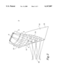
- FIG. 2 shows a side view of the head mounted display of the present invention.
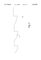
- FIG. 3 shows a magnified side view of the diffractive surface of the prism of the present invention.
- a configuration is a simple structure to display an image as well as the view in front of the user.
- FIG. 2 shows the present invention 2, which has a single prism 4 that replaces the relay system of the previous configurations.
- a flat panel display 6 of full color capability, or any image display device creates an image in the form of light beams that is sent through two lenses 8 and 9.
- the lenses 8 and 9 are used to correct for field aberrations.
- the number of lenses will vary depending on the aberration correction desired. However, due to weight limitations that are demanding, two lenses can adequately correct for most of the aberrations in the preferred embodiment.
- a high index of refraction lens is used in the present invention as an example of a preferred embodiment in order to make the system more compact, but not limited only this type of lens. Lenses are well known in this area of technology and will not be discussed in any further detail in this description.
- the beams of the image are then transmitted to a prism 4 which has a first surface 10 that is curved with a surface for diffraction.
- the curve is a tilted sphere and it is important to have a diffractive surface to correct for color aberrations for a full color system.
- FIG. 3 shows a greatly increased view of the diffractive surface 10.
- the height of the grooves 11 depends on the wavelength of the image source and the width of the grooves 11 is determined by the particular aberration function.
- the diffractive surface is a portion of a rotationally symmetric aberration function, which corrects astigmatism and chromatic aberration.
- the diffractive surface at the expense of diffractive efficiency, can be made bilaterally symmetric. This corrects for nonsymmetric aberrations and the equivalent performance can be achieved with one lens.
- the diffractive surface has an Optical Path Difference function of
- the beams of the image are then reflected off a second surface 12 which is a total internal reflective surface.
- the second surface 12 is flat or nearly flat.
- the total internal reflection will reduce the loss that usually occurs in reflection of beams. This gives the present invention much higher throughput to the eye.
- the prism 4 is tilted at an angle so that the beams reflecting off the second surface 12 are at large angles. To achieve this, the prism 4 must be tilted toward the user such that the angle of incidence on the second surface 12 is greater than approximately 40 degrees depending upon the optical material. To achieve this angle, the second surface 12 and third surface 14 tilt positions are varied to achieve the desired angles.
- the third surface 14 commonly referred to as the combiner surface, reflects the beams of the image to the user's eye.
- the shape of the third surface 14 is an aspherical toroid, but the present invention is not limited to this shape. This shape is used in the preferred embodiment since it is the preferred shape to correct for more aberrations such as astigmatism.
- the aspheric contour is given by
- the tilt of the third surface 14 can be any angle less than 30 degrees with the line of view axis 20. This allows for optimal reflection of the beams of the image with little or no loss. With this constraint in the tilt of the third surface 14, the second surface 12 is also constrained in its range of tilt to maintain the angle discussed above. The beams of the image are then reflected through the second surface 12 towards the user.
- a see through prism 16 is attached to the main prism 4 to allow the user to see the image as well as the external scene.
- the prisms of the preferred embodiment are made of polycarbonate, but any material that has good optical characteristics can be used. Polycarbonate is used in the present invention due to the low weight of the polycarbonate material and its good properties for molding.
- the shape of the see through prism 16 can be any shape to fit into the dimensions of the head mounted display 2 except for certain requirements on the surface 18 farthest to the eye of the user. This surface 18 must be nearly parallel with and concentric to the second surface 12 of the first prism 4 in order for the user to be able to see a unity power, distortion-free external scene.
- the system is highly corrected for coma, chromatic aberration, and astigmatism, which enables viewing of high resolution video imagery. This capability for full-color megapixel resolution is unique to previous designs shown. Most similar compact displays provide less than 200,000 pixel resolution.
- All of the optical surfaces for the preferred embodiment can be generated using single-point diamond-turning techniques on a polymer prism or a metal mold form, but other techniques such as a laser mask technique can be used depending on the diffractive function desired.
- the present invention provides an optical system 2 for a head-mounted display, and therefore has a very large exit pupil (at least 12 mm) so the eye will see a good image anywhere in that pupil location.
- the system 2 is a very fast optical system (F/1.7) and uses a 15.4 ⁇ 12.3 mm display device to deliver a 40° ⁇ 32° field of view to the eye. This allows for lucid viewing with a large field of view. These values are used for example purposes only in describing the preferred embodiment of the present invention.
- the present invention is not limited to these values and these values will vary with different requirements that may exist.
- Another advantage to the present invention over the previous configurations is that loss is decreased significantly. Previously, each component would add to the loss of the image so that the image was not as bright.
- the present invention uses a single component, the prism 4, which greatly decreases the loss of the image.
Landscapes
- Physics & Mathematics (AREA)
- General Physics & Mathematics (AREA)
- Optics & Photonics (AREA)
- Lenses (AREA)
- Devices For Indicating Variable Information By Combining Individual Elements (AREA)
- Instrument Panels (AREA)
Abstract
Description
OPD=-1.1565×10.sup.-3 r.sup.2 -9.7813×10.sup.-4 r.sup.4 +7.345×10.sup.-8 r.sup.6 -3.3602×10.sup.-10 r.sup.8 +5.9503×10.sup.-13 r.sup.10
z=-0.00496325y.sup.2 -3.4998×10.sup.-7 y.sup.4 +9.09557×10.sup.-11 y.sup.6 -3.57118×10.sup.-14 y.sup.8 +2.92877×10.sup.-18 y.sup.10
Claims (17)
Priority Applications (8)
| Application Number | Priority Date | Filing Date | Title |
|---|---|---|---|
| US09/304,361 US6147807A (en) | 1999-05-04 | 1999-05-04 | High brightness see-through head-mounted display |
| PCT/US2000/012265 WO2002101484A2 (en) | 1999-05-04 | 2000-05-04 | High brightness see-through head-mounted display |
| JP2003504181A JP2004522203A (en) | 1999-05-04 | 2000-05-04 | High-brightness head mounted display |
| IL14632400A IL146324A0 (en) | 1999-05-04 | 2000-05-04 | High brightness see-through head-mounted display |
| CA002415946A CA2415946A1 (en) | 1999-05-04 | 2000-05-04 | High brightness see-through head-mounted display |
| AT00993873T ATE287095T1 (en) | 1999-05-04 | 2000-05-04 | CLEAR HEAD-MOUNTED DISPLAY WITH HIGH BRIGHTNESS |
| DE60017472T DE60017472D1 (en) | 1999-05-04 | 2000-05-04 | TRANSPARENT HEAD-MOUNTED DISPLAY WITH HIGH BRIGHTNESS |
| EP00993873A EP1303782B1 (en) | 1999-05-04 | 2000-05-04 | High brightness see-through head-mounted display |
Applications Claiming Priority (1)
| Application Number | Priority Date | Filing Date | Title |
|---|---|---|---|
| US09/304,361 US6147807A (en) | 1999-05-04 | 1999-05-04 | High brightness see-through head-mounted display |
Publications (1)
| Publication Number | Publication Date |
|---|---|
| US6147807A true US6147807A (en) | 2000-11-14 |
Family
ID=23176196
Family Applications (1)
| Application Number | Title | Priority Date | Filing Date |
|---|---|---|---|
| US09/304,361 Expired - Lifetime US6147807A (en) | 1999-05-04 | 1999-05-04 | High brightness see-through head-mounted display |
Country Status (8)
| Country | Link |
|---|---|
| US (1) | US6147807A (en) |
| EP (1) | EP1303782B1 (en) |
| JP (1) | JP2004522203A (en) |
| AT (1) | ATE287095T1 (en) |
| CA (1) | CA2415946A1 (en) |
| DE (1) | DE60017472D1 (en) |
| IL (1) | IL146324A0 (en) |
| WO (1) | WO2002101484A2 (en) |
Cited By (39)
| Publication number | Priority date | Publication date | Assignee | Title |
|---|---|---|---|---|
| US20020176173A1 (en) * | 2001-04-30 | 2002-11-28 | Song Young-Ran | Wearable display system and process thereof |
| US6636356B2 (en) * | 2000-08-02 | 2003-10-21 | Olympus Optical Co., Ltd. | Observation optical system |
| US20060192306A1 (en) * | 2005-02-25 | 2006-08-31 | The Microoptical Corporation | Manufacturing methods for embedded optical system |
| US20060192307A1 (en) * | 2005-02-25 | 2006-08-31 | Eugene Giller | Method for producing high quality optical parts by casting |
| US20060262406A1 (en) * | 2005-05-17 | 2006-11-23 | Yaujen Wang | Dichroic beam splitter and related apparatus and methods |
| US7586686B1 (en) | 2006-04-14 | 2009-09-08 | Oasys Technology Llc | Eyepiece for head mounted display system and method of fabrication |
| US20100091027A1 (en) * | 2008-10-14 | 2010-04-15 | Canon Kabushiki Kaisha | Image processing apparatus and image processing method |
| US20100290127A1 (en) * | 2009-05-13 | 2010-11-18 | NVIS Inc. | Head-mounted optical apparatus using an oled display |
| WO2014145070A1 (en) | 2013-03-15 | 2014-09-18 | Immy Inc. | Head mounted display with non-pupil forming optical path |
| US9057826B2 (en) | 2013-01-31 | 2015-06-16 | Google Inc. | See-through near-to-eye display with eye prescription |
| US9250444B2 (en) | 2009-11-21 | 2016-02-02 | Immy Inc. | Head mounted display device |
| US9366869B2 (en) | 2014-11-10 | 2016-06-14 | Google Inc. | Thin curved eyepiece for see-through head wearable display |
| US9389422B1 (en) | 2013-12-23 | 2016-07-12 | Google Inc. | Eyepiece for head wearable display using partial and total internal reflections |
| US9395544B2 (en) | 2014-03-13 | 2016-07-19 | Google Inc. | Eyepiece with switchable reflector for head wearable display |
| US9442291B1 (en) | 2013-06-28 | 2016-09-13 | Google Inc. | Segmented diffractive optical elements for a head wearable display |
| US9459455B2 (en) | 2013-12-19 | 2016-10-04 | Google Inc. | See-through eyepiece for head wearable display |
| RU2616757C2 (en) * | 2013-02-22 | 2017-04-18 | Сейко Эпсон Корпорейшн | Method of making lightguide device, lightguide device and virtual images mapping device |
| US9632312B1 (en) | 2013-04-30 | 2017-04-25 | Google Inc. | Optical combiner with curved diffractive optical element |
| CN106855655A (en) * | 2015-12-08 | 2017-06-16 | 铭异科技股份有限公司 | Asymmetric curved surface prism image display optical system |
| US20170336639A1 (en) * | 2010-12-24 | 2017-11-23 | Magic Leap, Inc. | Ergonomic head mounted display device and optical system |
| US20170359558A1 (en) * | 2016-06-09 | 2017-12-14 | Japan Display Inc. | Display device and display method of the same |
| US9915823B1 (en) | 2014-05-06 | 2018-03-13 | Google Llc | Lightguide optical combiner for head wearable display |
| TWI635315B (en) * | 2015-07-06 | 2018-09-11 | 美商谷歌有限責任公司 | Adding prescriptive correction to eyepieces for see-through head wearable displays |
| US10162180B2 (en) | 2015-06-04 | 2018-12-25 | Google Llc | Efficient thin curved eyepiece for see-through head wearable display |
| US10345594B2 (en) | 2015-12-18 | 2019-07-09 | Ostendo Technologies, Inc. | Systems and methods for augmented near-eye wearable displays |
| US10353203B2 (en) | 2016-04-05 | 2019-07-16 | Ostendo Technologies, Inc. | Augmented/virtual reality near-eye displays with edge imaging lens comprising a plurality of display devices |
| US10386642B2 (en) | 2014-07-15 | 2019-08-20 | Samsung Electronics Co., Ltd. | Holographic see-through optical device, stereoscopic imaging system, and multimedia head mounted system |
| US10429646B2 (en) | 2015-10-28 | 2019-10-01 | Google Llc | Free space optical combiner with prescription integration |
| US10453431B2 (en) | 2016-04-28 | 2019-10-22 | Ostendo Technologies, Inc. | Integrated near-far light field display systems |
| US10522106B2 (en) | 2016-05-05 | 2019-12-31 | Ostendo Technologies, Inc. | Methods and apparatus for active transparency modulation |
| US10578882B2 (en) | 2015-12-28 | 2020-03-03 | Ostendo Technologies, Inc. | Non-telecentric emissive micro-pixel array light modulators and methods of fabrication thereof |
| US10598933B2 (en) | 2013-11-19 | 2020-03-24 | 3M Innovative Properties Company | See-through head mounted display with liquid crystal module for adjusting brightness ration of combined images |
| US10656421B2 (en) | 2014-07-11 | 2020-05-19 | Samsung Electronics Co., Ltd. | Lightguide structure, optical device and imaging system |
| US20210033868A1 (en) * | 2019-07-29 | 2021-02-04 | Canon Kabushiki Kaisha | Observation optical system and display apparatus |
| CN113204119A (en) * | 2021-04-30 | 2021-08-03 | 歌尔股份有限公司 | Cemented lens group and head-mounted display device |
| US11106273B2 (en) | 2015-10-30 | 2021-08-31 | Ostendo Technologies, Inc. | System and methods for on-body gestural interfaces and projection displays |
| US11209648B2 (en) | 2019-07-29 | 2021-12-28 | Canon Kabushiki Kaisha | Projection optical system and display apparatus having the same |
| US11493768B2 (en) * | 2018-07-17 | 2022-11-08 | Ostendo Technologies, Inc. | Augmented/virtual reality near eye display with edge imaging spectacle lens |
| US11609427B2 (en) | 2015-10-16 | 2023-03-21 | Ostendo Technologies, Inc. | Dual-mode augmented/virtual reality (AR/VR) near-eye wearable displays |
Citations (6)
| Publication number | Priority date | Publication date | Assignee | Title |
|---|---|---|---|---|
| US5459612A (en) * | 1992-08-12 | 1995-10-17 | Gec-Marconi Limited | Display system |
| US5537253A (en) * | 1993-02-01 | 1996-07-16 | Honeywell Inc. | Head mounted display utilizing diffractive optical elements |
| US5576887A (en) * | 1995-06-22 | 1996-11-19 | Honeywell Inc. | Head gear display system using off-axis image sources |
| US5706136A (en) * | 1995-02-28 | 1998-01-06 | Canon Kabushiki Kaisha | Optical system, and image observing apparatus and image pickup apparatus using it |
| US5818641A (en) * | 1995-10-16 | 1998-10-06 | Olympus Optical Co., Ltd. | Image display apparatus |
| US5875056A (en) * | 1995-05-18 | 1999-02-23 | Olympus Optical Co., Ltd. | Head or face mounted image display apparatus |
Family Cites Families (9)
| Publication number | Priority date | Publication date | Assignee | Title |
|---|---|---|---|---|
| GB8320945D0 (en) * | 1983-08-03 | 1983-09-07 | Marconi Avionics | Night vision goggles |
| US5224198A (en) * | 1991-09-30 | 1993-06-29 | Motorola, Inc. | Waveguide virtual image display |
| FR2712994B1 (en) * | 1993-11-22 | 1996-02-16 | Dubuisson Jean Sebastien | Visualization helmet. |
| JP3720464B2 (en) * | 1995-07-03 | 2005-11-30 | キヤノン株式会社 | Optical element and observation system using the same |
| JP3559624B2 (en) * | 1995-08-21 | 2004-09-02 | オリンパス株式会社 | Image display device |
| JP3636240B2 (en) * | 1996-03-25 | 2005-04-06 | オリンパス株式会社 | Optical system |
| JP3683339B2 (en) * | 1996-04-15 | 2005-08-17 | オリンパス株式会社 | Head-mounted image display device |
| JPH10282421A (en) * | 1997-02-07 | 1998-10-23 | Olympus Optical Co Ltd | Eccentric prism optical system |
| JPH10246865A (en) * | 1997-03-04 | 1998-09-14 | Olympus Optical Co Ltd | Visual display device |
-
1999
- 1999-05-04 US US09/304,361 patent/US6147807A/en not_active Expired - Lifetime
-
2000
- 2000-05-04 EP EP00993873A patent/EP1303782B1/en not_active Expired - Lifetime
- 2000-05-04 WO PCT/US2000/012265 patent/WO2002101484A2/en active IP Right Grant
- 2000-05-04 AT AT00993873T patent/ATE287095T1/en not_active IP Right Cessation
- 2000-05-04 IL IL14632400A patent/IL146324A0/en unknown
- 2000-05-04 DE DE60017472T patent/DE60017472D1/en not_active Expired - Lifetime
- 2000-05-04 JP JP2003504181A patent/JP2004522203A/en active Pending
- 2000-05-04 CA CA002415946A patent/CA2415946A1/en not_active Abandoned
Patent Citations (6)
| Publication number | Priority date | Publication date | Assignee | Title |
|---|---|---|---|---|
| US5459612A (en) * | 1992-08-12 | 1995-10-17 | Gec-Marconi Limited | Display system |
| US5537253A (en) * | 1993-02-01 | 1996-07-16 | Honeywell Inc. | Head mounted display utilizing diffractive optical elements |
| US5706136A (en) * | 1995-02-28 | 1998-01-06 | Canon Kabushiki Kaisha | Optical system, and image observing apparatus and image pickup apparatus using it |
| US5875056A (en) * | 1995-05-18 | 1999-02-23 | Olympus Optical Co., Ltd. | Head or face mounted image display apparatus |
| US5576887A (en) * | 1995-06-22 | 1996-11-19 | Honeywell Inc. | Head gear display system using off-axis image sources |
| US5818641A (en) * | 1995-10-16 | 1998-10-06 | Olympus Optical Co., Ltd. | Image display apparatus |
Cited By (60)
| Publication number | Priority date | Publication date | Assignee | Title |
|---|---|---|---|---|
| US6636356B2 (en) * | 2000-08-02 | 2003-10-21 | Olympus Optical Co., Ltd. | Observation optical system |
| US20020176173A1 (en) * | 2001-04-30 | 2002-11-28 | Song Young-Ran | Wearable display system and process thereof |
| US20060192306A1 (en) * | 2005-02-25 | 2006-08-31 | The Microoptical Corporation | Manufacturing methods for embedded optical system |
| US20060192307A1 (en) * | 2005-02-25 | 2006-08-31 | Eugene Giller | Method for producing high quality optical parts by casting |
| US7616378B2 (en) * | 2005-05-17 | 2009-11-10 | Northrop Grumman Corporation | Dichroic beam splitter and related apparatus and methods |
| US20060262406A1 (en) * | 2005-05-17 | 2006-11-23 | Yaujen Wang | Dichroic beam splitter and related apparatus and methods |
| US7586686B1 (en) | 2006-04-14 | 2009-09-08 | Oasys Technology Llc | Eyepiece for head mounted display system and method of fabrication |
| US20100091027A1 (en) * | 2008-10-14 | 2010-04-15 | Canon Kabushiki Kaisha | Image processing apparatus and image processing method |
| US8836720B2 (en) * | 2008-10-14 | 2014-09-16 | Canon Kabushiki Kaisha | Image processing apparatus and image processing method |
| US9595243B2 (en) | 2008-10-14 | 2017-03-14 | Cannon Kabushiki Kaisha | Image processing apparatus and image processing method |
| US20100290127A1 (en) * | 2009-05-13 | 2010-11-18 | NVIS Inc. | Head-mounted optical apparatus using an oled display |
| US8094377B2 (en) * | 2009-05-13 | 2012-01-10 | Nvis, Inc. | Head-mounted optical apparatus using an OLED display |
| US9250444B2 (en) | 2009-11-21 | 2016-02-02 | Immy Inc. | Head mounted display device |
| US20170336639A1 (en) * | 2010-12-24 | 2017-11-23 | Magic Leap, Inc. | Ergonomic head mounted display device and optical system |
| US9057826B2 (en) | 2013-01-31 | 2015-06-16 | Google Inc. | See-through near-to-eye display with eye prescription |
| RU2616757C2 (en) * | 2013-02-22 | 2017-04-18 | Сейко Эпсон Корпорейшн | Method of making lightguide device, lightguide device and virtual images mapping device |
| WO2014145060A1 (en) | 2013-03-15 | 2014-09-18 | Immy Inc. | Head mounted display having alignment maintained via structural frame |
| WO2014153225A1 (en) | 2013-03-15 | 2014-09-25 | Immy Inc. | Head mounted display assembly |
| US11187908B2 (en) | 2013-03-15 | 2021-11-30 | Immy Inc. | Head mounted display assembly with structural frame and separate outer frame |
| WO2014145070A1 (en) | 2013-03-15 | 2014-09-18 | Immy Inc. | Head mounted display with non-pupil forming optical path |
| US9268139B2 (en) | 2013-03-15 | 2016-02-23 | Immy Inc. | Head mounted display with micro-display alignment mechanism |
| US10078223B2 (en) | 2013-03-15 | 2018-09-18 | Immy Inc. | Head mounted display with non-pupil forming optical path |
| US9151954B2 (en) | 2013-03-15 | 2015-10-06 | Immy Inc. | Head mounted display having alignment maintained via structural frame |
| US9632312B1 (en) | 2013-04-30 | 2017-04-25 | Google Inc. | Optical combiner with curved diffractive optical element |
| US9442291B1 (en) | 2013-06-28 | 2016-09-13 | Google Inc. | Segmented diffractive optical elements for a head wearable display |
| US10598933B2 (en) | 2013-11-19 | 2020-03-24 | 3M Innovative Properties Company | See-through head mounted display with liquid crystal module for adjusting brightness ration of combined images |
| US9671614B2 (en) | 2013-12-19 | 2017-06-06 | Google Inc. | See-through eyepiece for head wearable display |
| US9459455B2 (en) | 2013-12-19 | 2016-10-04 | Google Inc. | See-through eyepiece for head wearable display |
| US9389422B1 (en) | 2013-12-23 | 2016-07-12 | Google Inc. | Eyepiece for head wearable display using partial and total internal reflections |
| US9395544B2 (en) | 2014-03-13 | 2016-07-19 | Google Inc. | Eyepiece with switchable reflector for head wearable display |
| US9915823B1 (en) | 2014-05-06 | 2018-03-13 | Google Llc | Lightguide optical combiner for head wearable display |
| US10656421B2 (en) | 2014-07-11 | 2020-05-19 | Samsung Electronics Co., Ltd. | Lightguide structure, optical device and imaging system |
| US10386642B2 (en) | 2014-07-15 | 2019-08-20 | Samsung Electronics Co., Ltd. | Holographic see-through optical device, stereoscopic imaging system, and multimedia head mounted system |
| US9366869B2 (en) | 2014-11-10 | 2016-06-14 | Google Inc. | Thin curved eyepiece for see-through head wearable display |
| US10162180B2 (en) | 2015-06-04 | 2018-12-25 | Google Llc | Efficient thin curved eyepiece for see-through head wearable display |
| US10146054B2 (en) * | 2015-07-06 | 2018-12-04 | Google Llc | Adding prescriptive correction to eyepieces for see-through head wearable displays |
| TWI635315B (en) * | 2015-07-06 | 2018-09-11 | 美商谷歌有限責任公司 | Adding prescriptive correction to eyepieces for see-through head wearable displays |
| US11609427B2 (en) | 2015-10-16 | 2023-03-21 | Ostendo Technologies, Inc. | Dual-mode augmented/virtual reality (AR/VR) near-eye wearable displays |
| US10429646B2 (en) | 2015-10-28 | 2019-10-01 | Google Llc | Free space optical combiner with prescription integration |
| US11106273B2 (en) | 2015-10-30 | 2021-08-31 | Ostendo Technologies, Inc. | System and methods for on-body gestural interfaces and projection displays |
| CN106855655A (en) * | 2015-12-08 | 2017-06-16 | 铭异科技股份有限公司 | Asymmetric curved surface prism image display optical system |
| US10585290B2 (en) | 2015-12-18 | 2020-03-10 | Ostendo Technologies, Inc | Systems and methods for augmented near-eye wearable displays |
| US10345594B2 (en) | 2015-12-18 | 2019-07-09 | Ostendo Technologies, Inc. | Systems and methods for augmented near-eye wearable displays |
| US11598954B2 (en) | 2015-12-28 | 2023-03-07 | Ostendo Technologies, Inc. | Non-telecentric emissive micro-pixel array light modulators and methods for making the same |
| US10578882B2 (en) | 2015-12-28 | 2020-03-03 | Ostendo Technologies, Inc. | Non-telecentric emissive micro-pixel array light modulators and methods of fabrication thereof |
| US10353203B2 (en) | 2016-04-05 | 2019-07-16 | Ostendo Technologies, Inc. | Augmented/virtual reality near-eye displays with edge imaging lens comprising a plurality of display devices |
| US11048089B2 (en) | 2016-04-05 | 2021-06-29 | Ostendo Technologies, Inc. | Augmented/virtual reality near-eye displays with edge imaging lens comprising a plurality of display devices |
| US10983350B2 (en) | 2016-04-05 | 2021-04-20 | Ostendo Technologies, Inc. | Augmented/virtual reality near-eye displays with edge imaging lens comprising a plurality of display devices |
| US10453431B2 (en) | 2016-04-28 | 2019-10-22 | Ostendo Technologies, Inc. | Integrated near-far light field display systems |
| US11145276B2 (en) | 2016-04-28 | 2021-10-12 | Ostendo Technologies, Inc. | Integrated near-far light field display systems |
| US10522106B2 (en) | 2016-05-05 | 2019-12-31 | Ostendo Technologies, Inc. | Methods and apparatus for active transparency modulation |
| US11175500B2 (en) | 2016-06-09 | 2021-11-16 | Japan Display Inc. | Display device and display method of the same |
| US20170359558A1 (en) * | 2016-06-09 | 2017-12-14 | Japan Display Inc. | Display device and display method of the same |
| US10564416B2 (en) * | 2016-06-09 | 2020-02-18 | Japan Display Inc. | Display device and display method of the same |
| US11493768B2 (en) * | 2018-07-17 | 2022-11-08 | Ostendo Technologies, Inc. | Augmented/virtual reality near eye display with edge imaging spectacle lens |
| US20210033868A1 (en) * | 2019-07-29 | 2021-02-04 | Canon Kabushiki Kaisha | Observation optical system and display apparatus |
| US11209648B2 (en) | 2019-07-29 | 2021-12-28 | Canon Kabushiki Kaisha | Projection optical system and display apparatus having the same |
| US11940623B2 (en) * | 2019-07-29 | 2024-03-26 | Canon Kabushiki Kaisha | Observation optical system and display apparatus |
| CN113204119A (en) * | 2021-04-30 | 2021-08-03 | 歌尔股份有限公司 | Cemented lens group and head-mounted display device |
| WO2022227538A1 (en) * | 2021-04-30 | 2022-11-03 | 歌尔股份有限公司 | Cemented lens group and head-mounted display device |
Also Published As
| Publication number | Publication date |
|---|---|
| ATE287095T1 (en) | 2005-01-15 |
| JP2004522203A (en) | 2004-07-22 |
| WO2002101484A2 (en) | 2002-12-19 |
| WO2002101484A3 (en) | 2003-02-06 |
| IL146324A0 (en) | 2004-05-12 |
| DE60017472D1 (en) | 2005-02-17 |
| CA2415946A1 (en) | 2002-12-19 |
| EP1303782B1 (en) | 2005-01-12 |
| EP1303782A2 (en) | 2003-04-23 |
Similar Documents
| Publication | Publication Date | Title |
|---|---|---|
| US6147807A (en) | High brightness see-through head-mounted display | |
| US5576887A (en) | Head gear display system using off-axis image sources | |
| US4761056A (en) | Compact helmet mounted display | |
| EP3889670B1 (en) | Optical system for a display with an off axis projector | |
| US11640050B2 (en) | Microdisplay-based head-up display system | |
| US5121099A (en) | Two-page automotive virtual image display | |
| US4968123A (en) | Helmet mounted display configured for simulator use | |
| US5526183A (en) | Helmet visor display employing reflective, refractive and diffractive optical elements | |
| JP2705880B2 (en) | Broad spectrum band virtual image display optical system | |
| US4269476A (en) | Helmet-mounted display system | |
| US5499139A (en) | Ultra-wide field of view, broad spectral band helmet visor display optical system | |
| JP2004536331A (en) | Lightweight head mounted display device | |
| US7525735B2 (en) | High resolution head mounted projection display | |
| CN1664649A (en) | Novel optical system of helmet display unit | |
| CN108501722B (en) | Vehicle-mounted display system | |
| EP0179124A1 (en) | Binocular holographic helmet mounted display. | |
| US5838490A (en) | Head mounted display system using mangin mirror combiner | |
| Huxford | Wide FOV head-mounted display using hybrid optics | |
| EP3349051B1 (en) | Collimation display apparatus, and vehicle-mounted or airborne head-up display apparatus | |
| CA2100520A1 (en) | Biocular helmet-mounted display optical system with interpupillar distance adjustment | |
| RU2771247C1 (en) | Collimator indicator system (variants) | |
| CA2052437C (en) | Two-page automotive virtual image display | |
| CN110646940A (en) | Folding optical system for motorcycle helmet | |
| WO2023249938A1 (en) | Anamorphic directional illumination device |
Legal Events
| Date | Code | Title | Description |
|---|---|---|---|
| AS | Assignment |
Owner name: HONEYWELL INC., MINNESOTA Free format text: ASSIGNMENT OF ASSIGNORS INTEREST;ASSIGNORS:DROESSLER, JUSTIN G.;FRITZ, TERESA A.;REEL/FRAME:009953/0539;SIGNING DATES FROM 19990426 TO 19990429 |
|
| STCF | Information on status: patent grant |
Free format text: PATENTED CASE |
|
| FEPP | Fee payment procedure |
Free format text: PAYOR NUMBER ASSIGNED (ORIGINAL EVENT CODE: ASPN); ENTITY STATUS OF PATENT OWNER: LARGE ENTITY |
|
| FEPP | Fee payment procedure |
Free format text: PAYER NUMBER DE-ASSIGNED (ORIGINAL EVENT CODE: RMPN); ENTITY STATUS OF PATENT OWNER: LARGE ENTITY Free format text: PAYOR NUMBER ASSIGNED (ORIGINAL EVENT CODE: ASPN); ENTITY STATUS OF PATENT OWNER: LARGE ENTITY |
|
| FPAY | Fee payment |
Year of fee payment: 4 |
|
| FPAY | Fee payment |
Year of fee payment: 8 |
|
| FPAY | Fee payment |
Year of fee payment: 12 |