US6055451A - Apparatus and method for determining tissue characteristics - Google Patents
Apparatus and method for determining tissue characteristics Download PDFInfo
- Publication number
- US6055451A US6055451A US08/990,069 US99006997A US6055451A US 6055451 A US6055451 A US 6055451A US 99006997 A US99006997 A US 99006997A US 6055451 A US6055451 A US 6055451A
- Authority
- US
- United States
- Prior art keywords
- target tissue
- electromagnetic radiation
- returned
- technique
- measurements
- Prior art date
- Legal status (The legal status is an assumption and is not a legal conclusion. Google has not performed a legal analysis and makes no representation as to the accuracy of the status listed.)
- Expired - Lifetime
Links
- 238000000034 method Methods 0.000 title claims abstract description 116
- 230000005670 electromagnetic radiation Effects 0.000 claims abstract description 124
- 230000005284 excitation Effects 0.000 claims abstract description 89
- 230000005855 radiation Effects 0.000 claims abstract description 73
- 230000010363 phase shift Effects 0.000 claims abstract description 39
- 238000005259 measurement Methods 0.000 claims description 56
- 230000010287 polarization Effects 0.000 claims description 30
- 238000000691 measurement method Methods 0.000 claims description 10
- 230000004044 response Effects 0.000 claims description 9
- 238000010521 absorption reaction Methods 0.000 claims description 7
- 230000002159 abnormal effect Effects 0.000 claims description 5
- 230000000007 visual effect Effects 0.000 claims description 4
- 229940079593 drug Drugs 0.000 claims description 3
- 239000003814 drug Substances 0.000 claims description 3
- 230000008569 process Effects 0.000 claims description 3
- 230000001225 therapeutic effect Effects 0.000 claims description 3
- 238000003909 pattern recognition Methods 0.000 claims description 2
- 238000011287 therapeutic dose Methods 0.000 claims description 2
- 238000012306 spectroscopic technique Methods 0.000 claims 21
- 230000001678 irradiating effect Effects 0.000 claims 7
- 238000013507 mapping Methods 0.000 claims 2
- 230000008878 coupling Effects 0.000 claims 1
- 238000010168 coupling process Methods 0.000 claims 1
- 238000005859 coupling reaction Methods 0.000 claims 1
- 239000013307 optical fiber Substances 0.000 description 37
- 239000000463 material Substances 0.000 description 8
- 201000010099 disease Diseases 0.000 description 7
- 208000037265 diseases, disorders, signs and symptoms Diseases 0.000 description 7
- 238000001727 in vivo Methods 0.000 description 6
- 210000001367 artery Anatomy 0.000 description 5
- 238000001514 detection method Methods 0.000 description 5
- 238000003745 diagnosis Methods 0.000 description 5
- 210000004204 blood vessel Anatomy 0.000 description 4
- 238000010586 diagram Methods 0.000 description 4
- 150000001875 compounds Chemical class 0.000 description 3
- 150000002500 ions Chemical class 0.000 description 3
- 239000000126 substance Substances 0.000 description 3
- 230000005653 Brownian motion process Effects 0.000 description 2
- 210000000481 breast Anatomy 0.000 description 2
- 238000005537 brownian motion Methods 0.000 description 2
- 239000000835 fiber Substances 0.000 description 2
- 230000006870 function Effects 0.000 description 2
- 238000003384 imaging method Methods 0.000 description 2
- 230000007774 longterm Effects 0.000 description 2
- 210000000056 organ Anatomy 0.000 description 2
- 230000000704 physical effect Effects 0.000 description 2
- 230000003595 spectral effect Effects 0.000 description 2
- 206010028980 Neoplasm Diseases 0.000 description 1
- 208000007256 Nevus Diseases 0.000 description 1
- 208000012641 Pigmentation disease Diseases 0.000 description 1
- 238000004458 analytical method Methods 0.000 description 1
- 238000013528 artificial neural network Methods 0.000 description 1
- QVGXLLKOCUKJST-UHFFFAOYSA-N atomic oxygen Chemical compound [O] QVGXLLKOCUKJST-UHFFFAOYSA-N 0.000 description 1
- 239000012620 biological material Substances 0.000 description 1
- 239000008280 blood Substances 0.000 description 1
- 210000004369 blood Anatomy 0.000 description 1
- 230000008081 blood perfusion Effects 0.000 description 1
- 210000005013 brain tissue Anatomy 0.000 description 1
- 230000008859 change Effects 0.000 description 1
- 210000001072 colon Anatomy 0.000 description 1
- 230000003111 delayed effect Effects 0.000 description 1
- 230000001419 dependent effect Effects 0.000 description 1
- 230000002999 depolarising effect Effects 0.000 description 1
- 238000000198 fluorescence anisotropy Methods 0.000 description 1
- 239000007789 gas Substances 0.000 description 1
- 210000001035 gastrointestinal tract Anatomy 0.000 description 1
- 230000003054 hormonal effect Effects 0.000 description 1
- 238000012623 in vivo measurement Methods 0.000 description 1
- 230000003993 interaction Effects 0.000 description 1
- 230000003902 lesion Effects 0.000 description 1
- 230000033001 locomotion Effects 0.000 description 1
- 239000003550 marker Substances 0.000 description 1
- 230000004060 metabolic process Effects 0.000 description 1
- 238000012986 modification Methods 0.000 description 1
- 230000004048 modification Effects 0.000 description 1
- 238000012544 monitoring process Methods 0.000 description 1
- 210000000653 nervous system Anatomy 0.000 description 1
- 239000001301 oxygen Substances 0.000 description 1
- 229910052760 oxygen Inorganic materials 0.000 description 1
- 230000019612 pigmentation Effects 0.000 description 1
- 238000005070 sampling Methods 0.000 description 1
- 238000001228 spectrum Methods 0.000 description 1
- 238000001356 surgical procedure Methods 0.000 description 1
- 238000012360 testing method Methods 0.000 description 1
Images


Classifications
-
- A—HUMAN NECESSITIES
- A61—MEDICAL OR VETERINARY SCIENCE; HYGIENE
- A61B—DIAGNOSIS; SURGERY; IDENTIFICATION
- A61B5/00—Measuring for diagnostic purposes; Identification of persons
- A61B5/0059—Measuring for diagnostic purposes; Identification of persons using light, e.g. diagnosis by transillumination, diascopy, fluorescence
- A61B5/0082—Measuring for diagnostic purposes; Identification of persons using light, e.g. diagnosis by transillumination, diascopy, fluorescence adapted for particular medical purposes
- A61B5/0084—Measuring for diagnostic purposes; Identification of persons using light, e.g. diagnosis by transillumination, diascopy, fluorescence adapted for particular medical purposes for introduction into the body, e.g. by catheters
- A61B5/0086—Measuring for diagnostic purposes; Identification of persons using light, e.g. diagnosis by transillumination, diascopy, fluorescence adapted for particular medical purposes for introduction into the body, e.g. by catheters using infrared radiation
-
- A—HUMAN NECESSITIES
- A61—MEDICAL OR VETERINARY SCIENCE; HYGIENE
- A61B—DIAGNOSIS; SURGERY; IDENTIFICATION
- A61B5/00—Measuring for diagnostic purposes; Identification of persons
- A61B5/0059—Measuring for diagnostic purposes; Identification of persons using light, e.g. diagnosis by transillumination, diascopy, fluorescence
- A61B5/0071—Measuring for diagnostic purposes; Identification of persons using light, e.g. diagnosis by transillumination, diascopy, fluorescence by measuring fluorescence emission
-
- A—HUMAN NECESSITIES
- A61—MEDICAL OR VETERINARY SCIENCE; HYGIENE
- A61B—DIAGNOSIS; SURGERY; IDENTIFICATION
- A61B5/00—Measuring for diagnostic purposes; Identification of persons
- A61B5/0059—Measuring for diagnostic purposes; Identification of persons using light, e.g. diagnosis by transillumination, diascopy, fluorescence
- A61B5/0075—Measuring for diagnostic purposes; Identification of persons using light, e.g. diagnosis by transillumination, diascopy, fluorescence by spectroscopy, i.e. measuring spectra, e.g. Raman spectroscopy, infrared absorption spectroscopy
-
- A—HUMAN NECESSITIES
- A61—MEDICAL OR VETERINARY SCIENCE; HYGIENE
- A61B—DIAGNOSIS; SURGERY; IDENTIFICATION
- A61B5/00—Measuring for diagnostic purposes; Identification of persons
- A61B5/0059—Measuring for diagnostic purposes; Identification of persons using light, e.g. diagnosis by transillumination, diascopy, fluorescence
- A61B5/0082—Measuring for diagnostic purposes; Identification of persons using light, e.g. diagnosis by transillumination, diascopy, fluorescence adapted for particular medical purposes
- A61B5/0084—Measuring for diagnostic purposes; Identification of persons using light, e.g. diagnosis by transillumination, diascopy, fluorescence adapted for particular medical purposes for introduction into the body, e.g. by catheters
Definitions
- the invention is related to apparatus and methods for determining tissue characteristics within a body of a patient.
- a detector detects the fluorescent radiation and analyzes the amplitudes and wavelengths of the emitted fluorescent radiation to determine whether the illuminated portion of the artery wall is normal, or covered with plaque.
- U.S. Pat. No. 4,930,516 to Alfano et al. discloses a method for detecting cancerous tissue, wherein a tissue sample is illuminated with excitation light at a first wavelength, and fluorescent radiation emitted in response to the excitation light is detected. The wavelength and amplitude of the emitted fluorescent radiation are then examined to determine whether the tissue sample is cancerous or normal. Normal tissue will typically have amplitude peaks at certain known wavelengths, whereas cancerous tissue will have amplitude peaks at different wavelengths. Alternatively the spectral amplitude of normal tissue will differ from cancerous tissue at the same wavelength.
- the disclosure of U.S. Pat. No. 4,930,516 is hereby incorporated by reference.
- a very short burst of excitation light is directed at a target tissue, and fluorescent emissions from the target tissue are then sensed with a detector.
- the amplitude of the fluorescent emissions are recorded, over time, as the fluorescent emissions decay.
- the fluorescent emissions may be sensed at specific wavelengths, or over a range of wavelengths.
- the amplitude decay profile, as a function of time, is then examined to determine a property or condition of the target tissue.
- U.S. Pat. No. 5,562,100 to Kittrell et al. discloses a method of determining tissue characteristics that includes illuminating a target tissue with a short pulse of excitation radiation at a particular wavelength, and detecting fluorescent radiation emitted by the target tissue in response to the excitation radiation. In this method, the amplitude of the emitted radiation is recorded, over time, as the emission decays. The amplitude profile is then used to determine characteristics of the target tissue.
- U.S. Pat. No. 5,467,767 to Alfano et al. also discloses a method of determining whether a tissue sample includes cancerous cells, wherein the amplitude decay profile of fluorescent emissions are examined. The contents of U.S. Pat. Nos. 5,562,100 and 5,467,767 are hereby incorporated by reference.
- U.S. patents have explained that the decay time of fluorescent emissions can be indirectly measured utilizing phase shift or polar anisotropy measurements.
- U.S. Pat. No. 5,624,847 to Lakowicz et al. discloses a method for determining the presence or concentration of various substances using a phase shift method.
- U.S. Pat. No. 5,515,864 to Zuckerman discloses a method for measuring the concentration of oxygen in blood utilizing a polar anisotropy measurement technique. Each of these methods indirectly measure the lifetime of fluorescent emissions generated in response to excitation radiation.
- the contents of U.S. Pat. Nos. 5,624,847 and 5,515,864 are hereby incorporated by reference.
- the invention encompasses apparatus and methods for determining characteristics of target tissues within a patient's body, wherein excitation electromagnetic radiation is used to illuminate a target tissue and electromagnetic radiation returned from the target tissue is analyzed to determine the characteristics of the target tissue.
- Some apparatus and methods embodying the invention can be used to perform a diagnosis at or slightly below the surface of a patient's tissues. For instance, methods and apparatus embodying the invention could be used to diagnose the condition of a patient's skin, the lining of natural body lumens such as the gastrointestinal tract, or the surfaces of body organs or blood vessels.
- apparatus and methods embodying the invention can be used to perform a diagnosis deep within a patient's body tissues where the excitation radiation has to pass through several centimeters of tissue before it interacts with the target tissue, such as in diagnosis of tumors and lesions deep in a patient's breast.
- the returned electromagnetic radiation can comprise only fluorescent emissions from the target tissue that are caused by the excitation electromagnetic radiation.
- apparatus or methods embodying the invention would measure the lifetime or decay time of the fluorescent emissions and use this information to determine characteristics of the target tissue.
- the fluorescent emissions may be generated by endogenous or exogenous fluorescent materials in the target tissue. Both phase shift and polar anisotropy techniques can be used to perform these types of measurements.
- the returned electromagnetic radiation can also comprise a portion of the excitation electromagnetic radiation that is scattered or reflected from or transmitted through the target tissue. Analysis of the scattered, reflected or transmitted excitation radiation gives a measure of absorption and scattering characteristics of the target tissue. This information can be used by itself to provide a diagnosis, or the information can be used to calibrate the results of the fluorescent emission measurements to arrive at a more accurate measurement.
- the reflected or scattered excitation radiation can be measured using intensity based techniques, or phase shift techniques.
- the excitation electromagnetic radiation is amplitude modulated at a predetermined frequency.
- a detector that senses the returned radiation is used to detect the amplitude and timing characteristics of the returned electromagnetic radiation.
- the excitation and returned radiation will have the same frequency, but the amplitude of the returned radiation should be smaller than the amplitude of the excitation radiation, and the returned radiation will be out of phase with the excitation radiation.
- the demodulation and phase shift between the excitation and returned electromagnetic radiation gives a measure of the characteristics of the target tissue.
- the demodulation amount can be represented by a demodulation factor , which is a ratio of the AC and DC amplitude components of the excitation and returned electromagnetic radiation.
- a polar anisotropy technique may also be used to detect fluorescent emissions to obtain a measure of the decay time or lifetime of the fluorescent emissions.
- the target tissue is illuminated with polarized excitation electromagnetic radiation.
- the returned fluorescent emissions are conveyed to a polarizing beam splitter that separates the returned electromagnetic radiation into two light beams that are polarized in mutually perpendicular planes.
- one plane is parallel to the polarization plane of the excitation radiation, and the second plane is perpendicular to that plane.
- Detectors detect the amplitudes of the two perpendicularly polarized beams of light. The detected amplitudes are used to calculate an anisotropy factor that is representative of the lifetime or decay time of the fluorescent emissions.
- the apparatus or method may only analyze returned radiation within certain predetermined wavelengths. Also, the apparatus and methods may only analyze fluorescent decays that occur for more than a predetermined period of time, or less than a predetermined period of time. This allows the device to distinguish between different types of tissues that have different fluorescent decay times.
- the above described techniques can be used to determine the conditions of multiple portions of a target tissue, and the determined conditions can be used to create a map of the target tissue. Such a map could then be either displayed on a display screen, or presented in hard copy format.
- An instrument embodying present invention could be in the form of an endoscope designed to be introduced into natural lumen or a cavity of a patient's body.
- the instrument might be in the form of a catheter designed to be introduced into blood vessels of a patient's body.
- the apparatus could include means for delivering a therapeutic pulse of electromagnetic radiation to the target tissue.
- the device could also include means for delivering a therapeutic dose of medication to the target tissue.
- the instrument could include means for sampling the target tissue depending upon the determined condition of the target tissue.
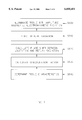
- FIG. 1 is a chart showing the amplitudes and phase shift of excitation and returned electromagnetic radiation
- FIG. 2 is a diagram showing an apparatus embodying the invention capable of performing a phase shift measurement
- FIG. 3 is a diagram showing an apparatus embodying of the invention capable of performing a polar anisotropy measurement
- FIG. 4 is a diagram of an endoscope embodying the invention.
- FIGS. 5A and 5B show an embodiment of the invention
- FIGS. 6A, 6B and 6C show the end portions of various embodiments of the invention.
- FIG. 7 shows the steps of a method embodying the invention.
- FIG. 8 shows the steps of another method embodying the invention.
- phase shift and polar anisotropy techniques that are the subject of the present invention are more simple and less expensive to implement than the known apparatus and techniques for detecting the lifetime or decay time of fluorescent emissions. As a result, they can be implemented for real world in vivo testing of target tissues.
- an excitation light is amplitude modulated at a constant frequency, instead of simply illuminating the target tissue with a short burst of light, the resulting fluorescence emissions will also appear to be amplitude modulated.
- the amplitude of the fluorescent emissions will be smaller than the amplitude of the excitation light, but the fluorescent emissions will have the same frequency. Also, there will be a phase shift between the excitation light and the fluorescent emissions.
- FIG. 1 illustrates the concept of illuminating a target tissue with amplitude modulated excitation electromagnetic radiation and sensing the resulting fluorescent emissions.
- the waveform X shows the amplitude of modulated excitation electromagnetic radiation from a source.
- the amplitude of returned fluorescent emissions is shown as waveform Y.
- the peaks of the waveform Y are delayed, or phase shifted, relative to the peaks of waveform X by an amount ⁇ . This is referred to as a phase shift amount.
- a demodulation factor m represents a ratio of the DC and AC components of the fluorescent emissions relative to the DC and AC components of the excitation electromagnetic radiation.
- Equation (2) The Fourier transform of equation (1), yields Equation (2), shown below.
- Equation (2) in turn, can be used to derive the phase shift and demodulation factor, as shown in Equations (3) and (4) below. ##EQU1##
- FIGS. 1 and 2 An apparatus for in vivo determination of the characteristics of a target tissue utilizing a phase shift technique will now be described with reference to FIGS. 1 and 2.
- the apparatus includes a source 20 of electromagnetic radiation, which is connected to a frequency synthesizer 46.
- the radiation source 20 produces electromagnetic radiation that is conducted to a target tissue 50.
- the radiation may be conducted to the target tissue 50 through one or more emission optical fibers 52.
- the apparatus may also include a filter 22 for controlling the electromagnetic radiation emitted from the radiation source 20.
- the radiation source could comprise a laser, a light emitting diode, a fluorescent tube, an incandescent bulb, or any other type of device that is capable of emitting electromagnetic radiation, as is well known to those skilled in the art.
- Electromagnetic radiation returned from target tissue 50 is sensed by a detector 56.
- the returned electromagnetic radiation could comprise either a portion of the excitation electromagnetic radiation that is scattered or reflected from the target tissue, or fluorescent emissions from fluorophores in the target tissue that have been excited by the excitation radiation.
- the detector may comprise a photomultiplier tube, a photosensitive diode, a charge coupled device, or any other type of electromagnetic radiation sensor, as is also well known to those skilled in the art.
- the detector is a small charge coupled device, it could be located at a distal end of an endoscope or catheter instrument. In this instance, the charge coupled device would already be located adjacent the target tissue such that the detector could directly sense the return radiation. The charge coupled device would then need some means for communicating its information to a processor 44.
- the returned electromagnetic radiation may be conducted to the detector 56 through one or more return optical fibers 54.
- the return optical fibers 54 and the excitation optical fibers 52 may be co-located within the same instrument, or they may be located in separate instruments. Alternately, the same optical fibers within an instrument may be used to perform both excitation and return functions.
- the frequency synthesizer 46 is a combination of two high frequency synthesizers that are preferably phase locked.
- the frequency synthesizer outputs three signals.
- the first signal has a frequency F
- the second signal has a frequency of F+f, which is a slightly in frequency than the signal F
- the third signal has a frequency f, which is lower in frequency than the first two signals.
- the excitation radiation from the radiation source 20, which illuminates the target tissue 50 is amplitude modulated at the high frequency F.
- the signal F+f drives the detector 56.
- the low frequency signal f which is readily derived as the difference between the two high frequency signals, is sent as a reference signal to the processor 44.
- the embodiment shown in FIG. 2 is a heterodyne system.
- the detector 56 senses the returned radiation and generates a signal that is modulated at the same frequency as the excitation radiation, or the frequency F.
- the detector 56 uses the higher frequency signal F+f to convert the signal corresponding to the returned radiation into a low difference frequency signal f', which includes information on the returned radiation signal.
- the low frequency signal f' is then compared to the low frequency signal f, which was generated by the frequency synthesizer 46, to calculate a phase shift ⁇ and demodulation factor m.
- Other types of heterodyne systems could also be used.
- the processor device 44 may include a memory 45 and a display 47. In fact, the processor device may comprise a typical personal computer.
- the processor 44 may also be configured to determine the AC and DC components of the amplitudes of the excitation and returned electromagnetic radiation signals.
- the processor may also be configured to calculate a demodulation factor m. As shown in FIG. 1, the demodulation factor m represents a ratio of the AC component B divided by the DC component A of the returned electromagnetic radiation to the AC component b divided by the DC component a of the excitation electromagnetic radiation.
- the demodulation factor can be used in conjunction with the phase difference ⁇ to more accurately determine characteristics of the target tissue.
- the phase difference and the demodulation factor will provide information about the absorption and reflection characteristics of the target tissue. If the detector 56 is measuring fluorescent radiation emitted by the target tissue, the phase difference and the demodulation factor will provide information about the lifetime and intensity of the fluorescent emissions. In either event, this information can be helpful in determining characteristics of the target tissue. For instance, this information can be used to determine whether a tissue is cancerous or not, the information can be used to distinguish between different types of tissue, and the information can be used to determine chemical properties or the concentrations of various chemicals or ions present in the target tissue.
- the fluorescent emissions can be generated by endogenous or exogenous fluorophores.
- the fluorescent material is exogenous, the material may be selected so that it chemically interacts with various compounds in the patient's body. In this instance, the fluorescent lifetime of the exogenous material would vary depending upon the presence or concentration of a compound or ion. As a result, the phase difference value, and/or the demodulation factor m can be used to determine the presence or concentration of the compound or ion. Examples of exogenous fluorescent materials that would be useful in a method as described above are set forth in U.S. Pat. No. 5,624,847 and U.S. Pat. No. 5,628,310, the contents of each of which are hereby incorporated by reference.
- a second apparatus and method embodying the invention which measures fluorescent lifetime via a polarization anisotropy measurement technique, will now be described with reference to FIG. 3.
- a polarized beam of electromagnetic radiation is used to illuminate a target tissue.
- Components of the fluorophores' excitation dipoles, parallel to the polarization plane of the beam of excitation electromagnetic radiation will then be selectively excited and will emit polarized fluorescent radiation.
- This emission will have a lifetime that is governed by the physiochemical environment of the fluorophore. Because of Brownian motion, the fluorophores will rotate as they emit radiation. This rotation results in a change in the intensity in each of the emission polarization planes.
- Brownian rotation in essence provides a time gated window in which to observe the intensity decay due to fluorescence lifetime.
- By measuring amplitudes of the emitted fluorescent radiation in mutually perpendicular planes it is possible to determine the lifetime, or decay time, of the fluorescent emissions. This measurement is possible only if the time constant of Brownian rotation, or the rotational correlation time, is not vastly different from the fluorescence lifetime.
- the time constant of Brownian rotation, or the rotational correlation time is not vastly different from the fluorescence lifetime.
- exogenous fluorophores can be engineered to satisfy this requirement for applications in disease detection.
- one polarization plane is parallel to the polarization plane of the excitation radiation, and the other is perpendicular to that plane.
- the Perrin Equation relates fluorescence anisotropy r to the fluorescent lifetime , where r 0 is the anisotropy of a molecule in the absence of Brownian motion (the frozen or highly viscous state) and is the rotational (Brownian) correlation time.
- Equation (6) is only valid for a single exponential decay of both fluorescence lifetime and anisotropy. Single exponential anisotropy decay only occurs for a spherical molecule. Also, for simplicity, the rotational correlation time for a sphere is defined according to Equation (7) below, where ⁇ is the viscosity, V the volume, R the universal gas constant, and T the absolute temperature.
- Equation (8) I l is the intensity of fluorescent emissions in a plane parallel to the plane of the excitation electromagnetic radiation, and I r is the intensity of fluorescent emissions in a plane perpendicular to the plane of the excitation electromagnetic radiation.
- a source of electromagnetic radiation 20 emits excitation radiation which then passes through a polarizer 24, focusing optics 25, and optionally an emission filter 26.
- the radiation source 20 can be a laser, a light emitting diode, a fluorescent light tube, an incandescent light bulb, or any other type of light emitting device.
- the radiation source 20 and the polarizer 24 could be replaced by a radiation source that emits polarized light.
- the polarized and filtered excitation radiation then passes through a dichroic mirror 28, additional focusing optics 30, and one or more optical fibers 31.
- the polarized excitation radiation exits the optical fibers 31 and illuminates a target tissue 50. Fluorophores in the target tissue 50 will emit fluorescent radiation in response to the excitation electromagnetic radiation.
- the returned electromagnetic radiation travels back up the optical fiber 31 and through the focusing optics 30.
- the optical fibers 31 comprise polarization preserving optical fibers such that the polarization of the excitation and return radiation is preserved as the radiation transits the fiber.
- one or more emission optical fibers may be used to communicate the excitation radiation to the target tissue 50, and a second group of return optical fibers may be used to communicate the return radiation back to the dichroic mirror 28.
- the returned radiation is then reflected by the dichroic mirror 28 through additional optics 29 and, optionally, another filter 32.
- the returned radiation then enters a polarizing beam splitter 34, which separates the returned electromagnetic radiation into two light beams that are polarized into mutually perpendicular planes.
- one polarization plane will be parallel to the polarization plane of the excitation radiation, and the other polarization plane will be perpendicular to that plane.
- a first one of the separated light beams having a first polarization plane illuminates a first detector 40A.
- a second of the separated light beams having a second polarization plane that is perpendicular to the first polarization plane illuminates a second detector 40B.
- the first and second detectors 40A and 40B output signals indicative of the amplitudes of the first and second light beams.
- the signals from the first and second detectors are then forwarded to a processor 44.
- the signals from the first and second detectors are used to calculate an anisotropy factor, which provides a measure of the lifetime of the fluorescent emissions. As described above, the fluorescent lifetime can be used to determine various characteristics of the target tissue.
- a device or method embodying the present invention utilizing either the phase shift or the polar anisotropy techniques make it possible to conduct in vivo measurements of tissues on the inside of body passages or lumens.
- An endoscope embodying the invention can be inserted into a natural body lumen of a patient to search for the presence of cancerous or diseased tissue. This means that no surgery would be required to locate and examine tissues inside the patient's body.
- Either the phase shift or the polar anisotropy method may be used to diagnose disease on the inside surfaces of a body lumen or tissues located immediately below the surface. Since the anisotropy detection method relies on polarized light, a reliable measurement of fluorescence lifetime can be made to a depth of several millimeters before losing resolution due to the depolarizing nature of tissue scattering.
- the phase shift technique is capable of conducting deep tissue measurements of tissues located several centimeters below the surface of a lumen or organ. This diagnosis is possible by either observing the returned scattered excitation radiation or by observing the scattered fluorescence radiation generated by tissue upon interaction with the scattered excitation radiation.
- a device embodying the invention that uses the phase shift technique can determine the presence of cancerous or diseased tissue located below or behind the surface of the body lumen or deep within tissue such as in breast or brain tissue.
- phase shift and demodulation factor of reflected/scattered excitation radiation and a measurement of the phase shift and demodulation factor of a fluorescent emission could be used together to obtain a more accurate determination of target tissue characteristics than one measurement alone.
- a phase shift and demodulation measurement could also be combined with a polar anisotropy measurement.
- phase shift and polar anisotropy techniques could be used in conjunction with known intensity based measurement techniques, as described above in the Background of The Invention, to obtain a better determination of target tissue characteristics.
- any of the above-described techniques could be used to determine a condition of a target tissue adjacent a distal end of a measuring device.
- the measuring device could then be moved adjacent a different portion of the target tissue, and the measurements could be repeated. This process could be repeated numerous times to determine the conditions of different portions of a target tissue area.
- the determined conditions could then be used to create a map of the target tissue area, which could be printed or displayed on a monitor.
- visual characteristics such as pigmentations (nevi) in skin, or polyps in the colon, can be used to identify potentially abnormal regions.
- Normalized or averaged spectra of multiple regions surrounding these potentially abnormal, visually distinct regions can be used to establish baseline measurements.
- the baseline measurements can then be compared to measurements taken on the abnormal, visually distinct regions. Measurements of normal and abnormal regions based on visual characteristics could be automated using imaging capabilities of the measurement device itself.
- measurements can be taken on spaced apart regions along a portion of a lumen or tissue. The spacing between the regions would be dependent on the type of tissue being diagnosed. Then, differentials between individual measurements taken at different regions would be calculated. If differentials are greater than a preset amount, the tissue between the excessively high differentials would be diagnosed as diseased.
- a gradient in spectral response as one moves away from a visually suspicious site could also be used as a marker for disease. This is easily automated and can be implemented effectively in any imaging modality.
- pattern recognition algorithms e.g. neural nets
- neural nets could also be used to analyze differences in readings taken from various sites in the same patient or from multiple readings from different patients.
- FIG. 4 shows an endoscope that could be used to practice any of the above-described measuring techniques.
- the endoscope 60 includes a transmit optical fiber bundle 52, which can convey excitation electromagnetic radiation from a radiation source 20 to a target tissue.
- the endoscope 60 also includes a return optical fiber bundle 54 for communicating reflected/scattered electromagnetic radiation or fluorescent emissions from a target tissue to a detector 56.
- the transmit and return optical fibers could be co-located, or could be the same fibers.
- the endoscope 60 may also include a handle 62 for positioning the endoscope, or for operating a device 64 on a distal end of the endoscope 60 intended to remove tissue samples from a patient.
- the endoscope may also include a device 66 for introducing a dose of medication to a target tissue.
- the source of electromagnetic radiation 20 may be configured to emit a burst of therapeutic radiation that could be delivered to a target tissue by the endoscope.
- FIGS. 5A and 5B show the structure of an endoscope or catheter which may embody the present invention.
- the apparatus includes a long body portion 70 which is intended to be inserted into a body of the patient.
- the body portion 70 In the case of a catheter, the body portion 70 must have a diameter sufficiently small to be inserted into blood vessels of the patient.
- the body portion of the device 70 In the case of an endoscope, the body portion of the device 70 must have a diameter that is sufficiently small to be inserted into a natural lumen or body cavity of the patient.
- the device includes a proximal end 80, which holds proximal ends of optical fibers 72a-72c.
- the optical fibers extend down the length of the device and terminate at a distal holding portion 74.
- the distal holding portion 74 holds the optical fibers in a predetermined orientation.
- the optical fibers are held such that they can illuminate selected portions of the distal end 76 of the device. This orientation also allows the distal end of the optical fibers to receive radiation from selected areas outside the distal end 76 of the device.
- the optical fibers are arranged such that there is a single central optical fiber 72a surrounded by a first ring of optical fibers 72B, which is in turn surrounded by a second ring of optical fibers 72c.
- first ring of optical fibers 72B which is in turn surrounded by a second ring of optical fibers 72c.
- other orientations of the optical fibers are possible.
- the central optical fiber 72a emits electromagnetic radiation 90 toward a target tissue, and returned electromagnetic radiation is sensed through the same optical fiber, the returned electromagnetic radiation can be analyzed using any of the above methods to determine characteristics of a target tissue located adjacent the center of the distal end of the device. The same process can be used to determine the condition of a target tissue at different locations around the distal end of the device.
- FIGS. 6A-6C show various different distal ends of the device.
- the distal ends of the optical fibers are held by a holding portion 98 that aims the distal ends of the optical fibers 97 in a particular direction.
- a flexible wire or bar 96 is attached to the holding portion 98 and extends to the proximal end of the device. By rotating the flexible wire or bar 96, the holding portion 98 can also be rotated. This allows the distal ends of the optical fibers to be aimed at different portions of the distal end of the device.
- FIG. 6B shows another embodiment of the invention that includes one or inflatable balloon portions 92a., 92b.
- An optical fiber 72 is located in the center of the device by a holding portion 94.
- Each of the inflatable balloons 92a, 92b is also held by the holding portion 94.
- the optical fiber 72 may be aimed to illuminate different portions of the distal end of the device or to receive return radiation from selected locations adjacent the distal end of the device.
- FIG. 6C shows an embodiment of the device similar to the embodiment shown in FIGS. 5A and 5B. This figure shows how electromagnetic radiation passing down through the optical fibers 72a-72c can be used to selectively illuminate material or tissue adjacent selected portions of the distal end of the device.
- FIG. 6C only the upper optical fibers are emitting electromagnetic radiation outside the device. This electromagnetic radiation is being used to destroy or atomize plaque which has formed on an inner wall of a blood vessel. By applying electromagnetic radiation to selected ones of the optical fibers, a doctor can carefully remove or correct problems with target tissues or materials.
- FIG. 7 shows steps of a method embodying the invention that can be used to determine the characteristics of a tissue adjacent a device embodying invention.
- a target tissue is illuminated with amplitude modulated excitation electromagnetic radiation.
- returned electromagnetic radiation is detected with a detector.
- a phase shift between the excitation and return electromagnetic radiation is calculated.
- a demodulation factor representing a ratio of the amplitudes of the excitation and return electromagnetic radiation is calculated. Step S630 is optional but may increase the accuracy of the results.
- characteristics of the target tissue are determined based on the calculated phase shift, and optionally the calculated demodulation factor.
- FIG. 8 shows another method embodying invention that can be used to determine tissue characteristics.
- the target tissue is illuminated with polarized electromagnetic radiation.
- the intensity of returned electromagnetic radiation is detected in mutually perpendicular polarization planes. In a preferred embodiment, the amplitude would be detected in planes that are parallel and perpendicular to the polarization plane of the excitation radiation.
- an anisotropy factor is calculated based on the detected intensity values for the different polarization planes.
- characteristics of a target tissue are determined based on the calculated anisotropy factor.
Abstract
Description
I(t)=I.sub.i e.sup.-t/τ Equation (1)
I(ω))=I.sub.i τ/(1-iωτ) Equation (2)
r.sub.0 /r=1+τ/φ Equation (6)
φ=(ηV)/(RT) Equation (7)
r=(I.sub.l -I.sub.r)/(I.sub.l +2I.sub.r) Equation (8)
Claims (48)
Priority Applications (4)
| Application Number | Priority Date | Filing Date | Title |
|---|---|---|---|
| US08/990,069 US6055451A (en) | 1997-12-12 | 1997-12-12 | Apparatus and method for determining tissue characteristics |
| PCT/US1998/025714 WO1999030608A1 (en) | 1997-12-12 | 1998-12-10 | Apparatus and method for determining tissue characteristics |
| AU16246/99A AU1624699A (en) | 1997-12-12 | 1998-12-10 | Apparatus and method for determining tissue characteristics |
| US10/337,687 US20030135122A1 (en) | 1997-12-12 | 2003-01-08 | Multi-modal optical tissue diagnostic system |
Applications Claiming Priority (1)
| Application Number | Priority Date | Filing Date | Title |
|---|---|---|---|
| US08/990,069 US6055451A (en) | 1997-12-12 | 1997-12-12 | Apparatus and method for determining tissue characteristics |
Related Child Applications (1)
| Application Number | Title | Priority Date | Filing Date |
|---|---|---|---|
| US43451899A Continuation-In-Part | 1997-12-12 | 1999-11-05 |
Publications (1)
| Publication Number | Publication Date |
|---|---|
| US6055451A true US6055451A (en) | 2000-04-25 |
Family
ID=25535734
Family Applications (1)
| Application Number | Title | Priority Date | Filing Date |
|---|---|---|---|
| US08/990,069 Expired - Lifetime US6055451A (en) | 1997-12-12 | 1997-12-12 | Apparatus and method for determining tissue characteristics |
Country Status (3)
| Country | Link |
|---|---|
| US (1) | US6055451A (en) |
| AU (1) | AU1624699A (en) |
| WO (1) | WO1999030608A1 (en) |
Cited By (63)
| Publication number | Priority date | Publication date | Assignee | Title |
|---|---|---|---|---|
| US6201989B1 (en) | 1997-03-13 | 2001-03-13 | Biomax Technologies Inc. | Methods and apparatus for detecting the rejection of transplanted tissue |
| US6371615B1 (en) * | 1999-04-29 | 2002-04-16 | Friedrich-Schiller-Universität Jena Buero für Furschungstransfer-Sachgebiet Schutzrechte | Method and apparatus for determining fluorophores on objects, especially on the living ocular fundus |
| US6418339B1 (en) * | 1997-05-26 | 2002-07-09 | Matthias Essenpreis | Method and apparatus for determining the lines of optimal direction for surgical cuts in the human skin |
| US20020120189A1 (en) * | 1999-07-27 | 2002-08-29 | Clarbruno Vedruccio | Electromagnetic analyzer of anisotropy in chemical organized systems |
| US6465968B1 (en) * | 1999-11-02 | 2002-10-15 | Fuji Photo Film Co., Ltd. | Method and apparatus for displaying fluorescence information |
| US20030135122A1 (en) * | 1997-12-12 | 2003-07-17 | Spectrx, Inc. | Multi-modal optical tissue diagnostic system |
| US6597946B2 (en) | 1998-11-09 | 2003-07-22 | Transpharma Ltd. | Electronic card for transdermal drug delivery and analyte extraction |
| US20030138378A1 (en) * | 2001-11-19 | 2003-07-24 | Dune Medical Devices Ltd. | Method and apparatus for examining tissue for predefined target cells, particularly cancerous cells, and a probe useful in such method and apparatus |
| US20030158470A1 (en) * | 2000-09-18 | 2003-08-21 | Sti Medical Systems, Inc. | Dual mode real-time screening and rapid full-area, selective-spectral, remote imaging and analysis device and process |
| US6611706B2 (en) | 1998-11-09 | 2003-08-26 | Transpharma Ltd. | Monopolar and bipolar current application for transdermal drug delivery and analyte extraction |
| US6615079B1 (en) | 1998-11-09 | 2003-09-02 | Elecsys Ltd. | Transdermal drug delivery and analyte extraction |
| US20030178578A1 (en) * | 2002-03-14 | 2003-09-25 | Govind Rao | Device for discrimination of fluorescence lifetimes and uses therefor |
| US6665556B1 (en) * | 1999-01-29 | 2003-12-16 | Robert R. Alfano | Method and apparatus for examining a tissue using the spectral wing emission therefrom induced by visible to infrared photoexcitation |
| US20030236453A1 (en) * | 2002-06-19 | 2003-12-25 | Simon Furnish | Multi-channel catheter tip |
| US20040010197A1 (en) * | 1998-09-11 | 2004-01-15 | Spectrx, Inc | Multi-modal optical tissue diagnostic system |
| US6708060B1 (en) | 1998-11-09 | 2004-03-16 | Transpharma Ltd. | Handheld apparatus and method for transdermal drug delivery and analyte extraction |
| WO2004023991A1 (en) | 2002-09-16 | 2004-03-25 | Joule Microsystems Canada Inc. | Optical system and use thereof for detecting patterns in biological tissue |
| US20040073133A1 (en) * | 2001-06-08 | 2004-04-15 | Yales David C. | System and method of measuring and controlling temperature of optical fiber tip in a laser system |
| US20040109478A1 (en) * | 2002-12-09 | 2004-06-10 | Infraredx, Inc. | Tunable spectroscopic source with power stability and method of operation |
| US20040147843A1 (en) * | 1999-11-05 | 2004-07-29 | Shabbir Bambot | System and method for determining tissue characteristics |
| US20040167406A1 (en) * | 1999-03-18 | 2004-08-26 | Milind Rajadhyaksha | System and method for enhancing confocal reflectance images of tissue specimens |
| US20050119605A1 (en) * | 2002-04-19 | 2005-06-02 | Transpharma Medical Ltd. | Handheld transdermal drug delivery and analyte extraction |
| US20050148881A1 (en) * | 2003-12-19 | 2005-07-07 | Fomitchov Ravel A. | High-frequency intensity-modulated incoherent optical source for biomedical optical imaging |
| US20050203419A1 (en) * | 2004-02-24 | 2005-09-15 | Nirmala Ramanujam | Side-firing probe for performing optical spectroscopy during core needle biopsy |
| US20050267340A1 (en) * | 2004-03-29 | 2005-12-01 | Olympus Corporation | In-vivo information measurement apparatus |
| US20050283195A1 (en) * | 2004-06-18 | 2005-12-22 | Pastore Joseph M | Methods and apparatuses for localizing myocardial infarction during catheterization |
| US20060184037A1 (en) * | 2004-11-30 | 2006-08-17 | Can Ince | Pulsed lighting imaging systems and methods |
| US20060264738A1 (en) * | 2003-07-24 | 2006-11-23 | Dune Medical Devices Ltd. | Method and apparatus for examining a substance, particularly tissue, to characterize its type |
| US20070019199A1 (en) * | 2005-07-25 | 2007-01-25 | The Wisconsin Alumni Research Foundation | Methods, systems, and computer program products for optimization of probes for spectroscopic measurement in turbid media |
| US20070032739A1 (en) * | 2005-08-04 | 2007-02-08 | Dune Medical Devices Ltd. | Device for forming an effective sensor-to-tissue contact |
| US20070032747A1 (en) * | 2005-08-04 | 2007-02-08 | Dune Medical Devices Ltd. | Tissue-characterization probe with effective sensor-to-tissue contact |
| US20070038126A1 (en) * | 2005-06-23 | 2007-02-15 | Pyle Jason L | System and method for monitoring of end organ oxygenation by measurement of in vivo cellular energy status |
| US20070179397A1 (en) * | 2002-01-04 | 2007-08-02 | Dune Medical Devices Ltd. | Probes, systems, and methods for examining tissue according to the dielectric properties thereof |
| WO2006072947A3 (en) * | 2005-01-04 | 2007-09-07 | Dune Medical Devices Ltd | Endoscopic system for in-vivo procedures |
| US20070232874A1 (en) * | 2003-10-03 | 2007-10-04 | Can Ince | System and method for imaging the reflectance of a substrate |
| US20070232932A1 (en) * | 2006-03-17 | 2007-10-04 | Duke University | Monte Carlo based model of fluorescence in turbid media and methods and systems for using same to determine intrinsic fluorescence of turbid media |
| US20080021343A1 (en) * | 2002-01-04 | 2008-01-24 | Dune Medical Devices Ltd. | Probes, systems, and methods for examining tissue according to the dielectric properties thereof |
| US20080270091A1 (en) * | 2007-02-23 | 2008-10-30 | Nirmala Ramanujam | Scaling method for fast monte carlo simulation of diffuse reflectance spectra from multi-layered turbid media and methods and systems for using same to determine optical properties of multi-layered turbid medium from measured diffuse reflectance |
| US20090015826A1 (en) * | 2006-03-30 | 2009-01-15 | Duke University | Optical assay system for intraoperative assessment of tumor margins |
| WO2009026459A1 (en) | 2007-08-22 | 2009-02-26 | Ric Investments, Llc | Compensating for system delay and/or extraneous illumination in analyte analyzation |
| US20090062637A1 (en) * | 2005-03-29 | 2009-03-05 | Dune Medical Devices Ltd. | Electromagnetic Sensors for Tissue Characterization |
| DE102008011013A1 (en) * | 2008-02-25 | 2009-09-03 | Labo Tech Labortechnik Gmbh | Method and device for complex metabolic analysis |
| US20090252682A1 (en) * | 2006-06-01 | 2009-10-08 | The General Hospital Corporation | In-vivo optical imaging method including analysis of dynamic images |
| US20100004520A1 (en) * | 2008-07-07 | 2010-01-07 | Kazuhiro Gono | Method and Apparatus for Foreign Matter Detection For Blood Content Sensors |
| US20100069720A1 (en) * | 2006-11-30 | 2010-03-18 | Newton Laboratories, Inc. | Spectroscopically enhanced imaging |
| US20100305436A1 (en) * | 2007-09-14 | 2010-12-02 | Light Sciences Oncology , Inc. | Systems, devices, and methods for photoactive assisted resection |
| US20110059016A1 (en) * | 2007-09-27 | 2011-03-10 | Nirmala Ramanujam | Optical assay system with a multi-probe imaging array |
| US20110105865A1 (en) * | 2008-04-24 | 2011-05-05 | Duke University | Diffuse reflectance spectroscopy device for quantifying tissue absorption and scattering |
| US20110112435A1 (en) * | 2007-09-28 | 2011-05-12 | Nirmala Ramanujam | Systems and methods for spectral analysis of a tissue mass using an instrument, an optical probe, and a monte carlo or a diffusion algorithm |
| US20110117025A1 (en) * | 2008-05-20 | 2011-05-19 | Ralph Sebastian Dacosta | Device and method for fluorescence-based imaging and monitoring |
| DE102010037406A1 (en) * | 2009-12-25 | 2011-06-30 | Michael Dr. med. 33824 Dickob | Arrangement for producing diagnostic relevant parameter of human cartilage-tissue in vivo during e.g. screening tests, has evaluation unit automatically evaluating fluorescent light detected by detection unit |
| DE102010016382A1 (en) * | 2010-04-09 | 2011-10-13 | Leica Microsystems Cms Gmbh | Fluorescence microscope and method for carrying out multiple positioning in a screening application |
| DE102010033427A1 (en) * | 2010-08-04 | 2012-02-09 | Karl Storz Gmbh & Co. Kg | Endoscope with adjustable viewing direction |
| US20120170037A1 (en) * | 2003-09-19 | 2012-07-05 | The General Hospital Corporation | Apparatus for imaging a tissue region |
| US8804115B2 (en) | 2008-04-25 | 2014-08-12 | Duke University | Systems and methods for performing optical spectroscopy using a self-calibrating fiber optic probe |
| US20140377792A1 (en) * | 2012-03-29 | 2014-12-25 | University Of Calcutta | Half-frequency spectral signatures |
| US9091637B2 (en) | 2009-12-04 | 2015-07-28 | Duke University | Smart fiber optic sensors systems and methods for quantitative optical spectroscopy |
| US9504826B2 (en) | 2009-02-18 | 2016-11-29 | Syneron Medical Ltd | Skin treatment apparatus for personal use and method for using same |
| US10438356B2 (en) | 2014-07-24 | 2019-10-08 | University Health Network | Collection and analysis of data for diagnostic purposes |
| US10709505B2 (en) | 2015-06-10 | 2020-07-14 | Boston Scientific Corporation | Bodily substance detection by evaluating photoluminescent response to excitation radiation |
| US11006093B1 (en) | 2020-01-22 | 2021-05-11 | Photonic Medical Inc. | Open view, multi-modal, calibrated digital loupe with depth sensing |
| WO2022150408A1 (en) * | 2021-01-05 | 2022-07-14 | Cytoveris Inc. | Multi-modal multi-spectral imaging system and method for characterizing tissue types in bladder specimens |
| US11954861B2 (en) | 2022-12-30 | 2024-04-09 | University Health Network | Systems, devices, and methods for visualization of tissue and collection and analysis of data regarding same |
Families Citing this family (1)
| Publication number | Priority date | Publication date | Assignee | Title |
|---|---|---|---|---|
| WO2008157406A1 (en) * | 2007-06-15 | 2008-12-24 | University Of Southern California | Pattern analysis of retinal maps for diagnosis of optic nerve diseases by optical coherence tomography |
Citations (172)
| Publication number | Priority date | Publication date | Assignee | Title |
|---|---|---|---|---|
| US3494354A (en) * | 1964-09-30 | 1970-02-10 | Tokyo Shibaura Electric Co | Flexible endoscope for use in cancer diagnosis |
| US4056724A (en) * | 1975-02-27 | 1977-11-01 | International Diagnostic Technology | Fluorometric system, method and test article |
| US4071020A (en) * | 1976-06-03 | 1978-01-31 | Xienta, Inc. | Apparatus and methods for performing in-vivo measurements of enzyme activity |
| US4084905A (en) * | 1976-03-11 | 1978-04-18 | Canadian Patents & Development Limited | Apparatus for detecting and measuring fluorescence emission |
| US4099872A (en) * | 1975-12-11 | 1978-07-11 | White John U | Fluorescence spectrophotometer |
| US4115699A (en) * | 1977-06-16 | 1978-09-19 | Kabushiki Kaisha Nihon Kotai Kenkyujo | Apparatus for sensitive detection and quantitative analysis of biological and biochemical substances |
| US4122348A (en) * | 1976-05-21 | 1978-10-24 | Elscint, Ltd. | Method of and apparatus for classifying biological cells |
| US4125828A (en) * | 1972-08-04 | 1978-11-14 | Med-El Inc. | Method and apparatus for automated classification and analysis of cells |
| US4127773A (en) * | 1977-03-31 | 1978-11-28 | Applied Photophysics Limited | Characterizing and identifying materials |
| US4131800A (en) * | 1976-06-13 | 1978-12-26 | Elscint Ltd. | Method of and apparatus for differentiating between normal and malignant cells |
| US4144456A (en) * | 1975-09-12 | 1979-03-13 | Sulzer Brothers Ltd. | Apparatus for irradiating a flowable substance |
| US4160016A (en) * | 1977-05-16 | 1979-07-03 | Syva Company | Receptor fluorescent immunoassay |
| US4161515A (en) * | 1973-10-02 | 1979-07-17 | Syva Company | Double receptor fluorescent immunoassay |
| US4162405A (en) * | 1978-05-23 | 1979-07-24 | Britton Chance | Flying spot fluoro-meter for oxidized flavoprotein and reduced pyridine nucleotide |
| US4203670A (en) * | 1977-04-21 | 1980-05-20 | Bromberg Nathan S | System and method of fluorescence polarimetry |
| US4223680A (en) * | 1977-06-28 | 1980-09-23 | Duke University, Inc. | Method and apparatus for monitoring metabolism in body organs in vivo |
| US4236526A (en) * | 1978-01-31 | 1980-12-02 | Richard Patricia A | Method of screening for sickle cell disease by detection of porphyrins and porphyrin metabolites in human dentition |
| US4266549A (en) * | 1978-10-12 | 1981-05-12 | Hiroaki Kimura | Laser scalpel |
| US4330207A (en) * | 1978-06-05 | 1982-05-18 | Hitachi, Ltd. | Fluorescence spectrophotometer |
| US4407964A (en) * | 1980-10-07 | 1983-10-04 | The Regents Of The University Of California | Homogeneous fluoroimmunoassay involving sensing radiation for forward and back directions |
| US4449535A (en) * | 1981-03-25 | 1984-05-22 | Compagnie Industrielle Des Lasers Cilas Alcatel | Apparatus for measuring in situ the state of oxidation-reduction of a living organ |
| US4501970A (en) * | 1982-10-12 | 1985-02-26 | Dynatech Laboratories Incorporated | Fluorometer |
| US4516856A (en) * | 1981-01-09 | 1985-05-14 | Abbott Laboratories | Optical apparatus for fluorescence polarization instrument |
| US4531834A (en) * | 1982-04-07 | 1985-07-30 | Hitachi, Ltd. | Fluorimeter |
| US4541438A (en) * | 1983-06-02 | 1985-09-17 | The Johns Hopkins University | Localization of cancerous tissue by monitoring infrared fluorescence emitted by intravenously injected porphyrin tumor-specific markers excited by long wavelength light |
| US4556057A (en) * | 1982-08-31 | 1985-12-03 | Hamamatsu Tv Co., Ltd. | Cancer diagnosis device utilizing laser beam pulses |
| US4577110A (en) * | 1983-04-11 | 1986-03-18 | Biochem Sensors, Inc. | Optical apparatus and method for measuring the characteristics of materials by their fluorescence |
| US4600306A (en) * | 1982-10-19 | 1986-07-15 | Horiba, Ltd. | Apparatus for measuring the luminous lifetime of a sample |
| US4632550A (en) * | 1983-10-13 | 1986-12-30 | Horiba, Ltd. | Measuring method for a time resolved emission spectrum or a time resolved excitation spectrum |
| US4643877A (en) * | 1983-08-12 | 1987-02-17 | Max Planck Gesellschaft Zur Foerderung Der Wissenschaften | Fluorometer |
| US4661711A (en) * | 1984-08-29 | 1987-04-28 | Labsystems Oy | Fluorometer |
| US4675529A (en) * | 1984-03-31 | 1987-06-23 | Olympus Optical Co., Ltd. | Fluorescent spectral analysis apparatus |
| US4681859A (en) * | 1984-09-21 | 1987-07-21 | Ortho Diagnostic Systems Inc. | Fluorescence polarization immunoassay for heavy antigens |
| US4682594A (en) * | 1985-03-11 | 1987-07-28 | Mcm Laboratories, Inc. | Probe-and-fire lasers |
| US4686371A (en) * | 1984-01-21 | 1987-08-11 | University Of Strathclyde | Apparatus for measuring fluorescence decay characteristics of materials |
| US4718417A (en) * | 1985-03-22 | 1988-01-12 | Massachusetts Institute Of Technology | Visible fluorescence spectral diagnostic for laser angiosurgery |
| US4722607A (en) * | 1985-04-15 | 1988-02-02 | Erwin Sick Gmbh Optik Elektronik | Luminescence sensor |
| US4751190A (en) * | 1985-07-22 | 1988-06-14 | Abbott Laboratories | Fluorescence polarization immunoassay and reagents for use therein |
| US4753530A (en) * | 1980-08-21 | 1988-06-28 | Oriel Scientific Ltd. | Analytical optical instruments |
| US4755684A (en) * | 1985-09-16 | 1988-07-05 | Avl Ag | Method for tumor diagnosis and arrangement for implementing this method |
| US4758727A (en) * | 1986-02-12 | 1988-07-19 | Ohio State University Research Foundation | Method and apparatus for the measurement of low-level laser-induced fluorescence |
| US4768513A (en) * | 1986-04-21 | 1988-09-06 | Agency Of Industrial Science And Technology | Method and device for measuring and processing light |
| US4786813A (en) * | 1984-10-22 | 1988-11-22 | Hightech Network Sci Ab | Fluorescence imaging system |
| US4786170A (en) * | 1985-07-26 | 1988-11-22 | Jenoptik Jena G.M.B.H. | Apparatus for the graphic representation and analysis of fluorescence signals |
| US4785806A (en) * | 1987-01-08 | 1988-11-22 | Yale University | Laser ablation process and apparatus |
| US4828984A (en) * | 1986-04-11 | 1989-05-09 | Flow Cytometry Standards Corporation | Composition, synthesis and use of simulated cells |
| US4833332A (en) * | 1987-06-12 | 1989-05-23 | E. I. Du Pont De Nemours And Company | Scanning fluorescent detection system |
| US4840485A (en) * | 1986-12-17 | 1989-06-20 | I.S.S. (U.S.A.) Inc. | Frequency domain cross-correlation fluorometry with phase-locked loop frequency synthesizers |
| US4852579A (en) * | 1987-04-20 | 1989-08-01 | Karl Storz Endoscopy Gmbh And Company | Photocharacterization and treatment of normal abnormal and ectopic endometrium |
| US4855930A (en) * | 1987-03-27 | 1989-08-08 | Chimerix Corporation | Method and appartatus for improved time-resolved fluorescence spectroscopy |
| US4877583A (en) * | 1987-04-01 | 1989-10-31 | Ajinomoto Company, Inc. | Fluorescent analyzer |
| US4877965A (en) * | 1985-07-01 | 1989-10-31 | Diatron Corporation | Fluorometer |
| US4894547A (en) * | 1987-09-28 | 1990-01-16 | Yale University | Optical method and apparatus for detecting and measuring aging, photoaging, dermal disease and pigmentation in skin |
| US4895156A (en) * | 1986-07-02 | 1990-01-23 | Schulze John E | Sensor system using fluorometric decay measurements |
| US4913142A (en) * | 1985-03-22 | 1990-04-03 | Massachusetts Institute Of Technology | Catheter for laser angiosurgery |
| US4925804A (en) * | 1986-06-17 | 1990-05-15 | Baxter International Inc. | Interligand metal transfer assay |
| US4930516A (en) * | 1985-11-13 | 1990-06-05 | Alfano Robert R | Method for detecting cancerous tissue using visible native luminescence |
| US4937457A (en) * | 1989-02-10 | 1990-06-26 | Slm Instruments, Inc. | Picosecond multi-harmonic fourier fluorometer |
| US4947850A (en) * | 1988-03-11 | 1990-08-14 | Trustees Of The University Of Pennsylvania | Method and apparatus for imaging an internal body portion of a host animal |
| US4957114A (en) * | 1985-04-01 | 1990-09-18 | Kun Zeng | Diagnostic apparatus for intrinsic fluorescence of malignant tumor |
| US4972331A (en) * | 1989-02-06 | 1990-11-20 | Nim, Inc. | Phase modulated spectrophotometry |
| US4973848A (en) * | 1989-07-28 | 1990-11-27 | J. Mccaughan | Laser apparatus for concurrent analysis and treatment |
| US4981138A (en) * | 1988-06-30 | 1991-01-01 | Yale University | Endoscopic fiberoptic fluorescence spectrometer |
| US5003977A (en) * | 1988-03-31 | 1991-04-02 | Agency Of Industrial Science And Technology | Device for analyzing fluorescent light signals |
| US5014707A (en) * | 1988-05-07 | 1991-05-14 | Carl-Zeiss-Stiftung | Apparatus for measuring and evaluating the inherent fluorescent spectra of organic tissue surfaces |
| US5021661A (en) * | 1989-09-04 | 1991-06-04 | Jeol Ltd. | Time-resolved infrared spectrophotometer |
| US5022757A (en) * | 1989-01-23 | 1991-06-11 | Modell Mark D | Heterodyne system and method for sensing a target substance |
| US5030832A (en) * | 1989-06-08 | 1991-07-09 | Minnesota Mining And Manufacturing Company | Apparatus for detecting fluorescence of a luminescent material |
| US5034010A (en) * | 1985-03-22 | 1991-07-23 | Massachusetts Institute Of Technology | Optical shield for a laser catheter |
| US5039219A (en) * | 1989-05-26 | 1991-08-13 | Photon Technology | Luminescence system and method for determining the nature of substances by measuring fluorescence and phosphorescence properties |
| US5043585A (en) * | 1990-01-03 | 1991-08-27 | Degussa Aktiengesellschaft | Method and apparatus for measurement of the fluorescence relaxation period of a fluorescent substance |
| US5042494A (en) * | 1985-11-13 | 1991-08-27 | Alfano Robert R | Method and apparatus for detecting cancerous tissue using luminescence excitation spectra |
| US5053626A (en) * | 1989-09-29 | 1991-10-01 | Boston University | Dual wavelength spectrofluorometer |
| US5061075A (en) * | 1989-08-07 | 1991-10-29 | Alfano Robert R | Optical method and apparatus for diagnosing human spermatozoa |
| US5061076A (en) * | 1989-01-31 | 1991-10-29 | Enzo Diagnostics, Inc. | Time-resolved fluorometer |
| US5062431A (en) * | 1988-11-08 | 1991-11-05 | Health Research, Inc. | In vivo fluorescence photometer |
| US5092331A (en) * | 1989-01-30 | 1992-03-03 | Olympus Optical Co., Ltd. | Fluorescence endoscopy and endoscopic device therefor |
| US5104392A (en) * | 1985-03-22 | 1992-04-14 | Massachusetts Institute Of Technology | Laser spectro-optic imaging for diagnosis and treatment of diseased tissue |
| US5106387A (en) * | 1985-03-22 | 1992-04-21 | Massachusetts Institute Of Technology | Method for spectroscopic diagnosis of tissue |
| US5115137A (en) * | 1989-02-22 | 1992-05-19 | Spectraphos Ab | Diagnosis by means of fluorescent light emission from tissue |
| US5119815A (en) * | 1988-12-21 | 1992-06-09 | Nim, Incorporated | Apparatus for determining the concentration of a tissue pigment of known absorbance, in vivo, using the decay characteristics of scintered electromagnetic radiation |
| US5122974A (en) * | 1989-02-06 | 1992-06-16 | Nim, Inc. | Phase modulated spectrophotometry |
| US5125404A (en) * | 1985-03-22 | 1992-06-30 | Massachusetts Institute Of Technology | Apparatus and method for obtaining spectrally resolved spatial images of tissue |
| US5127405A (en) * | 1990-02-16 | 1992-07-07 | The Boc Group, Inc. | Biomedical fiber optic probe with frequency domain signal processing |
| US5131398A (en) * | 1990-01-22 | 1992-07-21 | Mediscience Technology Corp. | Method and apparatus for distinguishing cancerous tissue from benign tumor tissue, benign tissue or normal tissue using native fluorescence |
| US5143066A (en) * | 1990-05-08 | 1992-09-01 | University Of Pittsburgh | Optical fiber sensors for continuous monitoring of biochemicals and related method |
| US5151869A (en) * | 1990-02-16 | 1992-09-29 | The Boc Group, Inc. | Frequency domain fluorometry using coherent sampling |
| US5168162A (en) * | 1991-02-04 | 1992-12-01 | Cornell Research Foundation, Inc. | Method of detecting the presence of anomalies in exfoliated cells using infrared spectroscopy |
| US5187672A (en) * | 1989-02-06 | 1993-02-16 | Nim Incorporated | Phase modulation spectroscopic system |
| US5196709A (en) * | 1991-05-03 | 1993-03-23 | University Of Maryland Systems | Fluorometry method and apparatus using a semiconductor laser diode as a light source |
| US5201318A (en) * | 1989-04-24 | 1993-04-13 | Rava Richard P | Contour mapping of spectral diagnostics |
| US5205291A (en) * | 1988-11-08 | 1993-04-27 | Health Research, Inc. | In vivo fluorescence photometer |
| US5212099A (en) * | 1991-01-18 | 1993-05-18 | Eastman Kodak Company | Method and apparatus for optically measuring concentration of an analyte |
| US5213105A (en) * | 1990-12-04 | 1993-05-25 | Research Corporation Technologies, Inc. | Frequency domain optical imaging using diffusion of intensity modulated radiation |
| US5257202A (en) * | 1989-02-13 | 1993-10-26 | Research Corporation Technologies, Inc. | Method and means for parallel frequency acquisition in frequency domain fluorometry |
| US5261410A (en) * | 1991-02-07 | 1993-11-16 | Alfano Robert R | Method for determining if a tissue is a malignant tumor tissue, a benign tumor tissue, or a normal or benign tissue using Raman spectroscopy |
| US5290275A (en) * | 1985-03-22 | 1994-03-01 | Massachusetts Institute Of Technology | Catheter for laser angiosurgery |
| US5293872A (en) * | 1991-04-03 | 1994-03-15 | Alfano Robert R | Method for distinguishing between calcified atherosclerotic tissue and fibrous atherosclerotic tissue or normal cardiovascular tissue using Raman spectroscopy |
| US5303026A (en) * | 1991-02-26 | 1994-04-12 | The Regents Of The University Of California Los Alamos National Laboratory | Apparatus and method for spectroscopic analysis of scattering media |
| US5304173A (en) | 1985-03-22 | 1994-04-19 | Massachusetts Institute Of Technology | Spectral diagonostic and treatment system |
| US5315993A (en) | 1990-02-16 | 1994-05-31 | The Boc Group, Inc. | Luminescence monitoring with modulation frequency multiplexing |
| US5318023A (en) | 1991-04-03 | 1994-06-07 | Cedars-Sinai Medical Center | Apparatus and method of use for a photosensitizer enhanced fluorescence based biopsy needle |
| US5323008A (en) | 1992-03-23 | 1994-06-21 | Diatron Corporation | Fluorometer detection system |
| US5329353A (en) | 1991-02-07 | 1994-07-12 | Research Development Corp. Of Japan | High sensitive multi-wavelength spectral analyzer |
| US5332905A (en) | 1992-08-26 | 1994-07-26 | Atto Instruments, Inc. | Apparatus and method for multiple emission ratio photometry and multiple emission ratio imaging |
| US5340716A (en) | 1991-06-20 | 1994-08-23 | Snytex (U.S.A.) Inc. | Assay method utilizing photoactivated chemiluminescent label |
| US5348890A (en) | 1991-12-04 | 1994-09-20 | Nof Corporation | Trioxane derivatives, and method for the chemiluminescence |
| US5348018A (en) | 1991-11-25 | 1994-09-20 | Alfano Robert R | Method for determining if tissue is malignant as opposed to non-malignant using time-resolved fluorescence spectroscopy |
| US5349954A (en) | 1993-07-23 | 1994-09-27 | General Electric Company | Tumor tissue characterization apparatus and method |
| US5353799A (en) | 1991-01-22 | 1994-10-11 | Non Invasive Technology, Inc. | Examination of subjects using photon migration with high directionality techniques |
| US5363854A (en) | 1990-08-24 | 1994-11-15 | U.S. Philips Corporation | Method of detecting anomalies of the skin, more particularly melanomae, and apparatus for carrying out the method |
| US5369496A (en) | 1989-11-13 | 1994-11-29 | Research Foundation Of City College Of New York | Noninvasive method and apparatus for characterizing biological materials |
| US5370119A (en) | 1991-01-04 | 1994-12-06 | Institut National De La Sante Et De La Recherche Medicale-Inserm | Device for measuring the pH of a target, method for using said device and applications thereof |
| US5377676A (en) | 1991-04-03 | 1995-01-03 | Cedars-Sinai Medical Center | Method for determining the biodistribution of substances using fluorescence spectroscopy |
| US5383467A (en) | 1992-11-18 | 1995-01-24 | Spectrascience, Inc. | Guidewire catheter and apparatus for diagnostic imaging |
| US5386827A (en) | 1993-03-30 | 1995-02-07 | Nim Incorporated | Quantitative and qualitative in vivo tissue examination using time resolved spectroscopy |
| US5395752A (en) | 1993-03-19 | 1995-03-07 | Ciba Corning Diagnostics Corp. | Long emission wavelength chemiluminescent compounds and their use in test assays |
| US5402778A (en) | 1993-01-19 | 1995-04-04 | Nim Incorporated | Spectrophotometric examination of tissue of small dimension |
| US5408996A (en) | 1993-03-25 | 1995-04-25 | Salb; Jesse | System and method for localization of malignant tissue |
| US5413108A (en) | 1993-04-21 | 1995-05-09 | The Research Foundation Of City College Of New York | Method and apparatus for mapping a tissue sample for and distinguishing different regions thereof based on luminescence measurements of cancer-indicative native fluorophor |
| US5419323A (en) | 1988-12-21 | 1995-05-30 | Massachusetts Institute Of Technology | Method for laser induced fluorescence of tissue |
| US5421339A (en) | 1993-05-12 | 1995-06-06 | Board Of Regents, The University Of Texas System | Diagnosis of dysplasia using laser induced fluoroescence |
| US5422719A (en) | 1993-11-12 | 1995-06-06 | Auburn International, Inc. | Multi-wave-length spectrofluorometer |
| US5421337A (en) | 1989-04-14 | 1995-06-06 | Massachusetts Institute Of Technology | Spectral diagnosis of diseased tissue |
| US5435307A (en) | 1991-03-29 | 1995-07-25 | The United States Of America As Represented By The Secretary Of The Department Of Health And Human Services | Surface fluorescent monitor |
| US5439000A (en) | 1992-11-18 | 1995-08-08 | Spectrascience, Inc. | Method of diagnosing tissue with guidewire |
| US5452723A (en) | 1992-07-24 | 1995-09-26 | Massachusetts Institute Of Technology | Calibrated spectrographic imaging |
| US5459323A (en) | 1990-01-12 | 1995-10-17 | University Of Salford | Measurement of luminescence |
| US5460971A (en) | 1990-01-12 | 1995-10-24 | Gottlieb; Amos J. | Sensor apparatus and analytical method |
| US5467767A (en) | 1991-11-25 | 1995-11-21 | Alfano; Robert R. | Method for determining if tissue is malignant as opposed to non-malignant using time-resolved fluorescence spectroscopy |
| US5474910A (en) | 1993-10-15 | 1995-12-12 | Alfano; Robert R. | Method and device for detecting biological molecules and/or microorganisms within a desired area or space |
| US5480775A (en) | 1990-01-26 | 1996-01-02 | Canon Kabushiki Kaisha | Method for measuring a specimen by the use of fluorescent light |
| US5485530A (en) | 1991-01-24 | 1996-01-16 | Joseph R. Lakowicz | Method and apparatus for multi-dimensional phase fluorescence lifetime imaging |
| US5491343A (en) | 1994-03-25 | 1996-02-13 | Brooker; Gary | High-speed multiple wavelength illumination source, apparatus containing the same, and applications thereof to methods of irradiating luminescent samples and of quantitative luminescence ratio microscopy |
| US5492118A (en) | 1993-12-16 | 1996-02-20 | Board Of Trustees Of The University Of Illinois | Determining material concentrations in tissues |
| US5497769A (en) | 1993-12-16 | 1996-03-12 | I.S.S. (Usa) Inc. | Photosensor with multiple light sources |
| US5500536A (en) | 1993-03-22 | 1996-03-19 | Hitachi, Ltd. | Spectrofluorometer |
| US5504336A (en) | 1993-05-18 | 1996-04-02 | Fuji Photo Film Co., Ltd. | Spectrofluorometric apparatus for obtaining spectral image information |
| US5507287A (en) | 1991-05-08 | 1996-04-16 | Xillix Technologies Corporation | Endoscopic imaging system for diseased tissue |
| US5517313A (en) | 1995-02-21 | 1996-05-14 | Colvin, Jr.; Arthur E. | Fluorescent optical sensor |
| US5515864A (en) | 1994-04-21 | 1996-05-14 | Zuckerman; Ralph | Method and apparatus for the in vivo measurement of oxygen concentration levels by the indirect determination of fluoescence lifetime |
| US5533508A (en) | 1991-10-31 | 1996-07-09 | Pdt Systems, Inc. | Vivo dosimeter for photodynamic therapy |
| US5548124A (en) | 1994-09-19 | 1996-08-20 | Hamamatsu Photonics K.K. | Decay characteristic measuring apparatus |
| US5553614A (en) | 1988-12-21 | 1996-09-10 | Non-Invasive Technology, Inc. | Examination of biological tissue using frequency domain spectroscopy |
| US5555885A (en) | 1988-12-21 | 1996-09-17 | Non-Invasive Technology, Inc. | Examination of breast tissue using time-resolved spectroscopy |
| US5557415A (en) | 1992-05-21 | 1996-09-17 | Faxekalk A/S | Apparatus and method for inducing and detecting fluorescence |
| US5565982A (en) | 1994-05-31 | 1996-10-15 | Recon Exploration | Apparatus and method for time resolved spectroscopy |
| US5564417A (en) | 1991-01-24 | 1996-10-15 | Non-Invasive Technology, Inc. | Pathlength corrected oximeter and the like |
| US5579773A (en) | 1994-09-30 | 1996-12-03 | Martin Marietta Energy Systems, Inc. | Laser-induced differential normalized fluorescence method for cancer diagnosis |
| US5582168A (en) | 1991-07-17 | 1996-12-10 | Georgia Tech Research Corp. | Apparatus and methods for measuring characteristics of biological tissues and similar materials |
| US5590660A (en) | 1994-03-28 | 1997-01-07 | Xillix Technologies Corp. | Apparatus and method for imaging diseased tissue using integrated autofluorescence |
| US5596992A (en) | 1993-06-30 | 1997-01-28 | Sandia Corporation | Multivariate classification of infrared spectra of cell and tissue samples |
| US5596987A (en) | 1988-11-02 | 1997-01-28 | Noninvasive Technology, Inc. | Optical coupler for in vivo examination of biological tissue |
| US5601079A (en) | 1992-03-12 | 1997-02-11 | Wong; Jacob Y. | Non-invasive quantification of glucose control, aging, and advanced maillard products by stimulated fluorescence |
| US5612540A (en) | 1995-03-31 | 1997-03-18 | Board Of Regents, The University Of Texas Systems | Optical method for the detection of cervical neoplasias using fluorescence spectroscopy |
| US5624847A (en) | 1991-05-03 | 1997-04-29 | Joseph R. Lakowicz | Method for optically measuring chemical analytes |
| US5628310A (en) | 1995-05-19 | 1997-05-13 | Joseph R. Lakowicz | Method and apparatus to perform trans-cutaneous analyte monitoring |
| US5635402A (en) | 1992-03-05 | 1997-06-03 | Alfano; Robert R. | Technique for determining whether a cell is malignant as opposed to non-malignant using extrinsic fluorescence spectroscopy |
| US5647368A (en) | 1996-02-28 | 1997-07-15 | Xillix Technologies Corp. | Imaging system for detecting diseased tissue using native fluorsecence in the gastrointestinal and respiratory tract |
| US5673701A (en) | 1994-10-07 | 1997-10-07 | Non Invasive Technology, Inc. | Optical techniques for examination of biological tissue |
| US5678550A (en) | 1995-08-11 | 1997-10-21 | The United States Of America As Represented By The Secretary Of The Department Of Health And Human Services | Apparatus and method for in situ detection of areas of cardiac electrical activity |
| US5683888A (en) | 1989-07-22 | 1997-11-04 | University Of Wales College Of Medicine | Modified bioluminescent proteins and their use |
| US5687730A (en) | 1991-01-22 | 1997-11-18 | Pdt Systems, Inc. | Apparatus for detecting the presence of abnormal tissue within a target tissue beneath the skin of a patient |
| US5697373A (en) | 1995-03-14 | 1997-12-16 | Board Of Regents, The University Of Texas System | Optical method and apparatus for the diagnosis of cervical precancers using raman and fluorescence spectroscopies |
| US5699795A (en) | 1995-03-31 | 1997-12-23 | Board Of Regents, The University Of Texas System | Optical probe for the detection of cervical neoplasia using fluorescence spectroscopy and apparatus incorporating same |
| US5699798A (en) | 1990-08-10 | 1997-12-23 | University Of Washington | Method for optically imaging solid tumor tissue |
| US5701903A (en) | 1994-06-23 | 1997-12-30 | Asahi Kogaku Kogyo Kabushiki Kaisha | Fluoroscopic apparatus |
| US5701902A (en) | 1994-09-14 | 1997-12-30 | Cedars-Sinai Medical Center | Spectroscopic burn injury evaluation apparatus and method |
| US5713352A (en) | 1994-12-21 | 1998-02-03 | Boehringer Mannheim Gmbh | Method for investigating a scattering medium with intensity-modulated light |
| US5713364A (en) | 1995-08-01 | 1998-02-03 | Medispectra, Inc. | Spectral volume microprobe analysis of materials |
| US5722406A (en) | 1995-03-23 | 1998-03-03 | U.S. Philips Corporation | Device for carrying out optical measurements in turbid media |
| US5762609A (en) | 1992-09-14 | 1998-06-09 | Sextant Medical Corporation | Device and method for analysis of surgical tissue interventions |
-
1997
- 1997-12-12 US US08/990,069 patent/US6055451A/en not_active Expired - Lifetime
-
1998
- 1998-12-10 WO PCT/US1998/025714 patent/WO1999030608A1/en active Application Filing
- 1998-12-10 AU AU16246/99A patent/AU1624699A/en not_active Abandoned
Patent Citations (182)
| Publication number | Priority date | Publication date | Assignee | Title |
|---|---|---|---|---|
| US3494354A (en) * | 1964-09-30 | 1970-02-10 | Tokyo Shibaura Electric Co | Flexible endoscope for use in cancer diagnosis |
| US4125828A (en) * | 1972-08-04 | 1978-11-14 | Med-El Inc. | Method and apparatus for automated classification and analysis of cells |
| US4161515A (en) * | 1973-10-02 | 1979-07-17 | Syva Company | Double receptor fluorescent immunoassay |
| US4056724A (en) * | 1975-02-27 | 1977-11-01 | International Diagnostic Technology | Fluorometric system, method and test article |
| US4144456A (en) * | 1975-09-12 | 1979-03-13 | Sulzer Brothers Ltd. | Apparatus for irradiating a flowable substance |
| US4099872A (en) * | 1975-12-11 | 1978-07-11 | White John U | Fluorescence spectrophotometer |
| US4084905A (en) * | 1976-03-11 | 1978-04-18 | Canadian Patents & Development Limited | Apparatus for detecting and measuring fluorescence emission |
| US4122348A (en) * | 1976-05-21 | 1978-10-24 | Elscint, Ltd. | Method of and apparatus for classifying biological cells |
| US4071020A (en) * | 1976-06-03 | 1978-01-31 | Xienta, Inc. | Apparatus and methods for performing in-vivo measurements of enzyme activity |
| US4131800A (en) * | 1976-06-13 | 1978-12-26 | Elscint Ltd. | Method of and apparatus for differentiating between normal and malignant cells |
| US4127773A (en) * | 1977-03-31 | 1978-11-28 | Applied Photophysics Limited | Characterizing and identifying materials |
| US4203670A (en) * | 1977-04-21 | 1980-05-20 | Bromberg Nathan S | System and method of fluorescence polarimetry |
| US4160016A (en) * | 1977-05-16 | 1979-07-03 | Syva Company | Receptor fluorescent immunoassay |
| US4115699A (en) * | 1977-06-16 | 1978-09-19 | Kabushiki Kaisha Nihon Kotai Kenkyujo | Apparatus for sensitive detection and quantitative analysis of biological and biochemical substances |
| US4223680A (en) * | 1977-06-28 | 1980-09-23 | Duke University, Inc. | Method and apparatus for monitoring metabolism in body organs in vivo |
| US4236526A (en) * | 1978-01-31 | 1980-12-02 | Richard Patricia A | Method of screening for sickle cell disease by detection of porphyrins and porphyrin metabolites in human dentition |
| US4162405A (en) * | 1978-05-23 | 1979-07-24 | Britton Chance | Flying spot fluoro-meter for oxidized flavoprotein and reduced pyridine nucleotide |
| US4330207A (en) * | 1978-06-05 | 1982-05-18 | Hitachi, Ltd. | Fluorescence spectrophotometer |
| US4266549A (en) * | 1978-10-12 | 1981-05-12 | Hiroaki Kimura | Laser scalpel |
| US4753530A (en) * | 1980-08-21 | 1988-06-28 | Oriel Scientific Ltd. | Analytical optical instruments |
| US4407964A (en) * | 1980-10-07 | 1983-10-04 | The Regents Of The University Of California | Homogeneous fluoroimmunoassay involving sensing radiation for forward and back directions |
| US4516856A (en) * | 1981-01-09 | 1985-05-14 | Abbott Laboratories | Optical apparatus for fluorescence polarization instrument |
| US4449535A (en) * | 1981-03-25 | 1984-05-22 | Compagnie Industrielle Des Lasers Cilas Alcatel | Apparatus for measuring in situ the state of oxidation-reduction of a living organ |
| US4531834A (en) * | 1982-04-07 | 1985-07-30 | Hitachi, Ltd. | Fluorimeter |
| US4556057A (en) * | 1982-08-31 | 1985-12-03 | Hamamatsu Tv Co., Ltd. | Cancer diagnosis device utilizing laser beam pulses |
| US4501970A (en) * | 1982-10-12 | 1985-02-26 | Dynatech Laboratories Incorporated | Fluorometer |
| US4600306A (en) * | 1982-10-19 | 1986-07-15 | Horiba, Ltd. | Apparatus for measuring the luminous lifetime of a sample |
| US4577110A (en) * | 1983-04-11 | 1986-03-18 | Biochem Sensors, Inc. | Optical apparatus and method for measuring the characteristics of materials by their fluorescence |
| US4541438A (en) * | 1983-06-02 | 1985-09-17 | The Johns Hopkins University | Localization of cancerous tissue by monitoring infrared fluorescence emitted by intravenously injected porphyrin tumor-specific markers excited by long wavelength light |
| US4643877A (en) * | 1983-08-12 | 1987-02-17 | Max Planck Gesellschaft Zur Foerderung Der Wissenschaften | Fluorometer |
| US4632550A (en) * | 1983-10-13 | 1986-12-30 | Horiba, Ltd. | Measuring method for a time resolved emission spectrum or a time resolved excitation spectrum |
| US4686371A (en) * | 1984-01-21 | 1987-08-11 | University Of Strathclyde | Apparatus for measuring fluorescence decay characteristics of materials |
| US4675529A (en) * | 1984-03-31 | 1987-06-23 | Olympus Optical Co., Ltd. | Fluorescent spectral analysis apparatus |
| US4661711A (en) * | 1984-08-29 | 1987-04-28 | Labsystems Oy | Fluorometer |
| US4681859A (en) * | 1984-09-21 | 1987-07-21 | Ortho Diagnostic Systems Inc. | Fluorescence polarization immunoassay for heavy antigens |
| US4786813A (en) * | 1984-10-22 | 1988-11-22 | Hightech Network Sci Ab | Fluorescence imaging system |
| US4682594A (en) * | 1985-03-11 | 1987-07-28 | Mcm Laboratories, Inc. | Probe-and-fire lasers |
| US5106387A (en) * | 1985-03-22 | 1992-04-21 | Massachusetts Institute Of Technology | Method for spectroscopic diagnosis of tissue |
| US5104392A (en) * | 1985-03-22 | 1992-04-14 | Massachusetts Institute Of Technology | Laser spectro-optic imaging for diagnosis and treatment of diseased tissue |
| US4913142A (en) * | 1985-03-22 | 1990-04-03 | Massachusetts Institute Of Technology | Catheter for laser angiosurgery |
| US5290275A (en) * | 1985-03-22 | 1994-03-01 | Massachusetts Institute Of Technology | Catheter for laser angiosurgery |
| US5034010A (en) * | 1985-03-22 | 1991-07-23 | Massachusetts Institute Of Technology | Optical shield for a laser catheter |
| US5304173A (en) | 1985-03-22 | 1994-04-19 | Massachusetts Institute Of Technology | Spectral diagonostic and treatment system |
| US5318024A (en) | 1985-03-22 | 1994-06-07 | Massachusetts Institute Of Technology | Laser endoscope for spectroscopic imaging |
| US5125404A (en) * | 1985-03-22 | 1992-06-30 | Massachusetts Institute Of Technology | Apparatus and method for obtaining spectrally resolved spatial images of tissue |
| US4718417A (en) * | 1985-03-22 | 1988-01-12 | Massachusetts Institute Of Technology | Visible fluorescence spectral diagnostic for laser angiosurgery |
| US4957114A (en) * | 1985-04-01 | 1990-09-18 | Kun Zeng | Diagnostic apparatus for intrinsic fluorescence of malignant tumor |
| US4722607A (en) * | 1985-04-15 | 1988-02-02 | Erwin Sick Gmbh Optik Elektronik | Luminescence sensor |
| US4877965A (en) * | 1985-07-01 | 1989-10-31 | Diatron Corporation | Fluorometer |
| US4751190A (en) * | 1985-07-22 | 1988-06-14 | Abbott Laboratories | Fluorescence polarization immunoassay and reagents for use therein |
| US4786170A (en) * | 1985-07-26 | 1988-11-22 | Jenoptik Jena G.M.B.H. | Apparatus for the graphic representation and analysis of fluorescence signals |
| US4755684A (en) * | 1985-09-16 | 1988-07-05 | Avl Ag | Method for tumor diagnosis and arrangement for implementing this method |
| US5042494A (en) * | 1985-11-13 | 1991-08-27 | Alfano Robert R | Method and apparatus for detecting cancerous tissue using luminescence excitation spectra |
| US4930516A (en) * | 1985-11-13 | 1990-06-05 | Alfano Robert R | Method for detecting cancerous tissue using visible native luminescence |
| US4930516B1 (en) * | 1985-11-13 | 1998-08-04 | Laser Diagnostic Instr Inc | Method for detecting cancerous tissue using visible native luminescence |
| US4758727A (en) * | 1986-02-12 | 1988-07-19 | Ohio State University Research Foundation | Method and apparatus for the measurement of low-level laser-induced fluorescence |
| US4828984A (en) * | 1986-04-11 | 1989-05-09 | Flow Cytometry Standards Corporation | Composition, synthesis and use of simulated cells |
| US4768513A (en) * | 1986-04-21 | 1988-09-06 | Agency Of Industrial Science And Technology | Method and device for measuring and processing light |
| US4925804A (en) * | 1986-06-17 | 1990-05-15 | Baxter International Inc. | Interligand metal transfer assay |
| US4895156A (en) * | 1986-07-02 | 1990-01-23 | Schulze John E | Sensor system using fluorometric decay measurements |
| US4840485A (en) * | 1986-12-17 | 1989-06-20 | I.S.S. (U.S.A.) Inc. | Frequency domain cross-correlation fluorometry with phase-locked loop frequency synthesizers |
| US4785806A (en) * | 1987-01-08 | 1988-11-22 | Yale University | Laser ablation process and apparatus |
| US4855930A (en) * | 1987-03-27 | 1989-08-08 | Chimerix Corporation | Method and appartatus for improved time-resolved fluorescence spectroscopy |
| US4877583A (en) * | 1987-04-01 | 1989-10-31 | Ajinomoto Company, Inc. | Fluorescent analyzer |
| US4852579A (en) * | 1987-04-20 | 1989-08-01 | Karl Storz Endoscopy Gmbh And Company | Photocharacterization and treatment of normal abnormal and ectopic endometrium |
| US4833332A (en) * | 1987-06-12 | 1989-05-23 | E. I. Du Pont De Nemours And Company | Scanning fluorescent detection system |
| US4894547A (en) * | 1987-09-28 | 1990-01-16 | Yale University | Optical method and apparatus for detecting and measuring aging, photoaging, dermal disease and pigmentation in skin |
| US4947850A (en) * | 1988-03-11 | 1990-08-14 | Trustees Of The University Of Pennsylvania | Method and apparatus for imaging an internal body portion of a host animal |
| US5003977A (en) * | 1988-03-31 | 1991-04-02 | Agency Of Industrial Science And Technology | Device for analyzing fluorescent light signals |
| US5014707A (en) * | 1988-05-07 | 1991-05-14 | Carl-Zeiss-Stiftung | Apparatus for measuring and evaluating the inherent fluorescent spectra of organic tissue surfaces |
| US4981138A (en) * | 1988-06-30 | 1991-01-01 | Yale University | Endoscopic fiberoptic fluorescence spectrometer |
| US5596987A (en) | 1988-11-02 | 1997-01-28 | Noninvasive Technology, Inc. | Optical coupler for in vivo examination of biological tissue |
| US5062431A (en) * | 1988-11-08 | 1991-11-05 | Health Research, Inc. | In vivo fluorescence photometer |
| US5111821A (en) * | 1988-11-08 | 1992-05-12 | Health Research, Inc. | Fluorometric method for detecting abnormal tissue using dual long-wavelength excitation |
| US5205291A (en) * | 1988-11-08 | 1993-04-27 | Health Research, Inc. | In vivo fluorescence photometer |
| US5419323A (en) | 1988-12-21 | 1995-05-30 | Massachusetts Institute Of Technology | Method for laser induced fluorescence of tissue |
| US5553614A (en) | 1988-12-21 | 1996-09-10 | Non-Invasive Technology, Inc. | Examination of biological tissue using frequency domain spectroscopy |
| US5562100A (en) | 1988-12-21 | 1996-10-08 | Massachusetts Institute Of Technology | Method for laser induced fluorescence of tissue |
| US5555885A (en) | 1988-12-21 | 1996-09-17 | Non-Invasive Technology, Inc. | Examination of breast tissue using time-resolved spectroscopy |
| US5119815A (en) * | 1988-12-21 | 1992-06-09 | Nim, Incorporated | Apparatus for determining the concentration of a tissue pigment of known absorbance, in vivo, using the decay characteristics of scintered electromagnetic radiation |
| US5022757A (en) * | 1989-01-23 | 1991-06-11 | Modell Mark D | Heterodyne system and method for sensing a target substance |
| US5092331A (en) * | 1989-01-30 | 1992-03-03 | Olympus Optical Co., Ltd. | Fluorescence endoscopy and endoscopic device therefor |
| US5061076A (en) * | 1989-01-31 | 1991-10-29 | Enzo Diagnostics, Inc. | Time-resolved fluorometer |
| US5122974A (en) * | 1989-02-06 | 1992-06-16 | Nim, Inc. | Phase modulated spectrophotometry |
| US4972331A (en) * | 1989-02-06 | 1990-11-20 | Nim, Inc. | Phase modulated spectrophotometry |
| US5187672A (en) * | 1989-02-06 | 1993-02-16 | Nim Incorporated | Phase modulation spectroscopic system |
| US4937457A (en) * | 1989-02-10 | 1990-06-26 | Slm Instruments, Inc. | Picosecond multi-harmonic fourier fluorometer |
| US5257202A (en) * | 1989-02-13 | 1993-10-26 | Research Corporation Technologies, Inc. | Method and means for parallel frequency acquisition in frequency domain fluorometry |
| US5115137A (en) * | 1989-02-22 | 1992-05-19 | Spectraphos Ab | Diagnosis by means of fluorescent light emission from tissue |
| US5421337A (en) | 1989-04-14 | 1995-06-06 | Massachusetts Institute Of Technology | Spectral diagnosis of diseased tissue |
| US5201318A (en) * | 1989-04-24 | 1993-04-13 | Rava Richard P | Contour mapping of spectral diagnostics |
| US5345941A (en) | 1989-04-24 | 1994-09-13 | Massachusetts Institute Of Technology | Contour mapping of spectral diagnostics |
| US5039219A (en) * | 1989-05-26 | 1991-08-13 | Photon Technology | Luminescence system and method for determining the nature of substances by measuring fluorescence and phosphorescence properties |
| US5030832A (en) * | 1989-06-08 | 1991-07-09 | Minnesota Mining And Manufacturing Company | Apparatus for detecting fluorescence of a luminescent material |
| US5683888A (en) | 1989-07-22 | 1997-11-04 | University Of Wales College Of Medicine | Modified bioluminescent proteins and their use |
| US4973848A (en) * | 1989-07-28 | 1990-11-27 | J. Mccaughan | Laser apparatus for concurrent analysis and treatment |
| US5061075A (en) * | 1989-08-07 | 1991-10-29 | Alfano Robert R | Optical method and apparatus for diagnosing human spermatozoa |
| US5021661A (en) * | 1989-09-04 | 1991-06-04 | Jeol Ltd. | Time-resolved infrared spectrophotometer |
| US5053626A (en) * | 1989-09-29 | 1991-10-01 | Boston University | Dual wavelength spectrofluorometer |
| US5369496A (en) | 1989-11-13 | 1994-11-29 | Research Foundation Of City College Of New York | Noninvasive method and apparatus for characterizing biological materials |
| US5043585A (en) * | 1990-01-03 | 1991-08-27 | Degussa Aktiengesellschaft | Method and apparatus for measurement of the fluorescence relaxation period of a fluorescent substance |
| US5459323A (en) | 1990-01-12 | 1995-10-17 | University Of Salford | Measurement of luminescence |
| US5460971A (en) | 1990-01-12 | 1995-10-24 | Gottlieb; Amos J. | Sensor apparatus and analytical method |
| US5131398A (en) * | 1990-01-22 | 1992-07-21 | Mediscience Technology Corp. | Method and apparatus for distinguishing cancerous tissue from benign tumor tissue, benign tissue or normal tissue using native fluorescence |
| US5480775A (en) | 1990-01-26 | 1996-01-02 | Canon Kabushiki Kaisha | Method for measuring a specimen by the use of fluorescent light |
| US5127405A (en) * | 1990-02-16 | 1992-07-07 | The Boc Group, Inc. | Biomedical fiber optic probe with frequency domain signal processing |
| US5315993A (en) | 1990-02-16 | 1994-05-31 | The Boc Group, Inc. | Luminescence monitoring with modulation frequency multiplexing |
| US5151869A (en) * | 1990-02-16 | 1992-09-29 | The Boc Group, Inc. | Frequency domain fluorometry using coherent sampling |
| US5143066A (en) * | 1990-05-08 | 1992-09-01 | University Of Pittsburgh | Optical fiber sensors for continuous monitoring of biochemicals and related method |
| US5699798A (en) | 1990-08-10 | 1997-12-23 | University Of Washington | Method for optically imaging solid tumor tissue |
| US5363854A (en) | 1990-08-24 | 1994-11-15 | U.S. Philips Corporation | Method of detecting anomalies of the skin, more particularly melanomae, and apparatus for carrying out the method |
| US5213105A (en) * | 1990-12-04 | 1993-05-25 | Research Corporation Technologies, Inc. | Frequency domain optical imaging using diffusion of intensity modulated radiation |
| US5370119A (en) | 1991-01-04 | 1994-12-06 | Institut National De La Sante Et De La Recherche Medicale-Inserm | Device for measuring the pH of a target, method for using said device and applications thereof |
| US5212099A (en) * | 1991-01-18 | 1993-05-18 | Eastman Kodak Company | Method and apparatus for optically measuring concentration of an analyte |
| US5664574A (en) | 1991-01-22 | 1997-09-09 | Non-Invasive Technology, Inc. | System for tissue examination using directional optical radiation |
| US5687730A (en) | 1991-01-22 | 1997-11-18 | Pdt Systems, Inc. | Apparatus for detecting the presence of abnormal tissue within a target tissue beneath the skin of a patient |
| US5353799A (en) | 1991-01-22 | 1994-10-11 | Non Invasive Technology, Inc. | Examination of subjects using photon migration with high directionality techniques |
| US5485530A (en) | 1991-01-24 | 1996-01-16 | Joseph R. Lakowicz | Method and apparatus for multi-dimensional phase fluorescence lifetime imaging |
| US5564417A (en) | 1991-01-24 | 1996-10-15 | Non-Invasive Technology, Inc. | Pathlength corrected oximeter and the like |
| US5168162A (en) * | 1991-02-04 | 1992-12-01 | Cornell Research Foundation, Inc. | Method of detecting the presence of anomalies in exfoliated cells using infrared spectroscopy |
| US5261410A (en) * | 1991-02-07 | 1993-11-16 | Alfano Robert R | Method for determining if a tissue is a malignant tumor tissue, a benign tumor tissue, or a normal or benign tissue using Raman spectroscopy |
| US5329353A (en) | 1991-02-07 | 1994-07-12 | Research Development Corp. Of Japan | High sensitive multi-wavelength spectral analyzer |
| US5303026A (en) * | 1991-02-26 | 1994-04-12 | The Regents Of The University Of California Los Alamos National Laboratory | Apparatus and method for spectroscopic analysis of scattering media |
| US5435307A (en) | 1991-03-29 | 1995-07-25 | The United States Of America As Represented By The Secretary Of The Department Of Health And Human Services | Surface fluorescent monitor |
| US5377676A (en) | 1991-04-03 | 1995-01-03 | Cedars-Sinai Medical Center | Method for determining the biodistribution of substances using fluorescence spectroscopy |
| US5318023A (en) | 1991-04-03 | 1994-06-07 | Cedars-Sinai Medical Center | Apparatus and method of use for a photosensitizer enhanced fluorescence based biopsy needle |
| US5293872A (en) * | 1991-04-03 | 1994-03-15 | Alfano Robert R | Method for distinguishing between calcified atherosclerotic tissue and fibrous atherosclerotic tissue or normal cardiovascular tissue using Raman spectroscopy |
| US5196709A (en) * | 1991-05-03 | 1993-03-23 | University Of Maryland Systems | Fluorometry method and apparatus using a semiconductor laser diode as a light source |
| US5624847A (en) | 1991-05-03 | 1997-04-29 | Joseph R. Lakowicz | Method for optically measuring chemical analytes |
| US5507287A (en) | 1991-05-08 | 1996-04-16 | Xillix Technologies Corporation | Endoscopic imaging system for diseased tissue |
| US5340716A (en) | 1991-06-20 | 1994-08-23 | Snytex (U.S.A.) Inc. | Assay method utilizing photoactivated chemiluminescent label |
| US5582168A (en) | 1991-07-17 | 1996-12-10 | Georgia Tech Research Corp. | Apparatus and methods for measuring characteristics of biological tissues and similar materials |
| US5533508A (en) | 1991-10-31 | 1996-07-09 | Pdt Systems, Inc. | Vivo dosimeter for photodynamic therapy |
| US5348018A (en) | 1991-11-25 | 1994-09-20 | Alfano Robert R | Method for determining if tissue is malignant as opposed to non-malignant using time-resolved fluorescence spectroscopy |
| US5467767A (en) | 1991-11-25 | 1995-11-21 | Alfano; Robert R. | Method for determining if tissue is malignant as opposed to non-malignant using time-resolved fluorescence spectroscopy |
| US5348890A (en) | 1991-12-04 | 1994-09-20 | Nof Corporation | Trioxane derivatives, and method for the chemiluminescence |
| US5635402A (en) | 1992-03-05 | 1997-06-03 | Alfano; Robert R. | Technique for determining whether a cell is malignant as opposed to non-malignant using extrinsic fluorescence spectroscopy |
| US5601079A (en) | 1992-03-12 | 1997-02-11 | Wong; Jacob Y. | Non-invasive quantification of glucose control, aging, and advanced maillard products by stimulated fluorescence |
| US5323008A (en) | 1992-03-23 | 1994-06-21 | Diatron Corporation | Fluorometer detection system |
| US5557415A (en) | 1992-05-21 | 1996-09-17 | Faxekalk A/S | Apparatus and method for inducing and detecting fluorescence |
| US5807263A (en) | 1992-06-17 | 1998-09-15 | Non-Invasivie Technology, Inc. | Imaging of biological tissue using photon migration with high directionality techniques |
| US5452723A (en) | 1992-07-24 | 1995-09-26 | Massachusetts Institute Of Technology | Calibrated spectrographic imaging |
| US5332905A (en) | 1992-08-26 | 1994-07-26 | Atto Instruments, Inc. | Apparatus and method for multiple emission ratio photometry and multiple emission ratio imaging |
| US5762609A (en) | 1992-09-14 | 1998-06-09 | Sextant Medical Corporation | Device and method for analysis of surgical tissue interventions |
| US5601087A (en) | 1992-11-18 | 1997-02-11 | Spectrascience, Inc. | System for diagnosing tissue with guidewire |
| US5383467A (en) | 1992-11-18 | 1995-01-24 | Spectrascience, Inc. | Guidewire catheter and apparatus for diagnostic imaging |
| US5439000A (en) | 1992-11-18 | 1995-08-08 | Spectrascience, Inc. | Method of diagnosing tissue with guidewire |
| US5402778A (en) | 1993-01-19 | 1995-04-04 | Nim Incorporated | Spectrophotometric examination of tissue of small dimension |
| US5395752A (en) | 1993-03-19 | 1995-03-07 | Ciba Corning Diagnostics Corp. | Long emission wavelength chemiluminescent compounds and their use in test assays |
| US5500536A (en) | 1993-03-22 | 1996-03-19 | Hitachi, Ltd. | Spectrofluorometer |
| US5408996A (en) | 1993-03-25 | 1995-04-25 | Salb; Jesse | System and method for localization of malignant tissue |
| US5386827A (en) | 1993-03-30 | 1995-02-07 | Nim Incorporated | Quantitative and qualitative in vivo tissue examination using time resolved spectroscopy |
| US5413108A (en) | 1993-04-21 | 1995-05-09 | The Research Foundation Of City College Of New York | Method and apparatus for mapping a tissue sample for and distinguishing different regions thereof based on luminescence measurements of cancer-indicative native fluorophor |
| US5421339A (en) | 1993-05-12 | 1995-06-06 | Board Of Regents, The University Of Texas System | Diagnosis of dysplasia using laser induced fluoroescence |
| US5623932A (en) | 1993-05-12 | 1997-04-29 | Board Of Regents, The University Of Texas System | Diagnosis of dysplasia using laser induced fluorescence |
| US5504336A (en) | 1993-05-18 | 1996-04-02 | Fuji Photo Film Co., Ltd. | Spectrofluorometric apparatus for obtaining spectral image information |
| US5596992A (en) | 1993-06-30 | 1997-01-28 | Sandia Corporation | Multivariate classification of infrared spectra of cell and tissue samples |
| US5349954A (en) | 1993-07-23 | 1994-09-27 | General Electric Company | Tumor tissue characterization apparatus and method |
| US5474910A (en) | 1993-10-15 | 1995-12-12 | Alfano; Robert R. | Method and device for detecting biological molecules and/or microorganisms within a desired area or space |
| US5422719A (en) | 1993-11-12 | 1995-06-06 | Auburn International, Inc. | Multi-wave-length spectrofluorometer |
| US5492118A (en) | 1993-12-16 | 1996-02-20 | Board Of Trustees Of The University Of Illinois | Determining material concentrations in tissues |
| US5497769A (en) | 1993-12-16 | 1996-03-12 | I.S.S. (Usa) Inc. | Photosensor with multiple light sources |
| US5491343A (en) | 1994-03-25 | 1996-02-13 | Brooker; Gary | High-speed multiple wavelength illumination source, apparatus containing the same, and applications thereof to methods of irradiating luminescent samples and of quantitative luminescence ratio microscopy |
| US5590660A (en) | 1994-03-28 | 1997-01-07 | Xillix Technologies Corp. | Apparatus and method for imaging diseased tissue using integrated autofluorescence |
| US5515864A (en) | 1994-04-21 | 1996-05-14 | Zuckerman; Ralph | Method and apparatus for the in vivo measurement of oxygen concentration levels by the indirect determination of fluoescence lifetime |
| US5626134A (en) | 1994-04-21 | 1997-05-06 | Zuckerman; Ralph | Method and apparatus for the measurement of analyte concentration levels by the steady-state determination of fluorescence lifetime |
| US5565982A (en) | 1994-05-31 | 1996-10-15 | Recon Exploration | Apparatus and method for time resolved spectroscopy |
| US5701903A (en) | 1994-06-23 | 1997-12-30 | Asahi Kogaku Kogyo Kabushiki Kaisha | Fluoroscopic apparatus |
| US5701902A (en) | 1994-09-14 | 1997-12-30 | Cedars-Sinai Medical Center | Spectroscopic burn injury evaluation apparatus and method |
| US5548124A (en) | 1994-09-19 | 1996-08-20 | Hamamatsu Photonics K.K. | Decay characteristic measuring apparatus |
| US5579773A (en) | 1994-09-30 | 1996-12-03 | Martin Marietta Energy Systems, Inc. | Laser-induced differential normalized fluorescence method for cancer diagnosis |
| US5673701A (en) | 1994-10-07 | 1997-10-07 | Non Invasive Technology, Inc. | Optical techniques for examination of biological tissue |
| US5713352A (en) | 1994-12-21 | 1998-02-03 | Boehringer Mannheim Gmbh | Method for investigating a scattering medium with intensity-modulated light |
| US5517313A (en) | 1995-02-21 | 1996-05-14 | Colvin, Jr.; Arthur E. | Fluorescent optical sensor |
| US5697373A (en) | 1995-03-14 | 1997-12-16 | Board Of Regents, The University Of Texas System | Optical method and apparatus for the diagnosis of cervical precancers using raman and fluorescence spectroscopies |
| US5722406A (en) | 1995-03-23 | 1998-03-03 | U.S. Philips Corporation | Device for carrying out optical measurements in turbid media |
| US5699795A (en) | 1995-03-31 | 1997-12-23 | Board Of Regents, The University Of Texas System | Optical probe for the detection of cervical neoplasia using fluorescence spectroscopy and apparatus incorporating same |
| US5612540A (en) | 1995-03-31 | 1997-03-18 | Board Of Regents, The University Of Texas Systems | Optical method for the detection of cervical neoplasias using fluorescence spectroscopy |
| US5628310A (en) | 1995-05-19 | 1997-05-13 | Joseph R. Lakowicz | Method and apparatus to perform trans-cutaneous analyte monitoring |
| US5713364A (en) | 1995-08-01 | 1998-02-03 | Medispectra, Inc. | Spectral volume microprobe analysis of materials |
| US5678550A (en) | 1995-08-11 | 1997-10-21 | The United States Of America As Represented By The Secretary Of The Department Of Health And Human Services | Apparatus and method for in situ detection of areas of cardiac electrical activity |
| US5647368A (en) | 1996-02-28 | 1997-07-15 | Xillix Technologies Corp. | Imaging system for detecting diseased tissue using native fluorsecence in the gastrointestinal and respiratory tract |
Cited By (125)
| Publication number | Priority date | Publication date | Assignee | Title |
|---|---|---|---|---|
| US6201989B1 (en) | 1997-03-13 | 2001-03-13 | Biomax Technologies Inc. | Methods and apparatus for detecting the rejection of transplanted tissue |
| US6418339B1 (en) * | 1997-05-26 | 2002-07-09 | Matthias Essenpreis | Method and apparatus for determining the lines of optimal direction for surgical cuts in the human skin |
| US20030135122A1 (en) * | 1997-12-12 | 2003-07-17 | Spectrx, Inc. | Multi-modal optical tissue diagnostic system |
| US20040010197A1 (en) * | 1998-09-11 | 2004-01-15 | Spectrx, Inc | Multi-modal optical tissue diagnostic system |
| US20060089556A1 (en) * | 1998-09-11 | 2006-04-27 | Spectrx, Inc. | Multi-modal optical tissue diagnostic system |
| US6615079B1 (en) | 1998-11-09 | 2003-09-02 | Elecsys Ltd. | Transdermal drug delivery and analyte extraction |
| US20030208152A1 (en) * | 1998-11-09 | 2003-11-06 | Zohar Avrahami | Electronic card for transdermal drug delivery and analyte extraction |
| US6711435B2 (en) | 1998-11-09 | 2004-03-23 | Transpharma Ltd. | Transdermal drug delivery and analyte extraction |
| US6708060B1 (en) | 1998-11-09 | 2004-03-16 | Transpharma Ltd. | Handheld apparatus and method for transdermal drug delivery and analyte extraction |
| US6611706B2 (en) | 1998-11-09 | 2003-08-26 | Transpharma Ltd. | Monopolar and bipolar current application for transdermal drug delivery and analyte extraction |
| US20040230227A1 (en) * | 1998-11-09 | 2004-11-18 | Zohar Avrahami | Handheld apparatus and method for transdermal drug delivery and analyte extraction |
| US7164942B2 (en) | 1998-11-09 | 2007-01-16 | Transpharma Medical Ltd. | Handheld apparatus and method for transdermal drug delivery and analyte extraction |
| US6597946B2 (en) | 1998-11-09 | 2003-07-22 | Transpharma Ltd. | Electronic card for transdermal drug delivery and analyte extraction |
| US6665556B1 (en) * | 1999-01-29 | 2003-12-16 | Robert R. Alfano | Method and apparatus for examining a tissue using the spectral wing emission therefrom induced by visible to infrared photoexcitation |
| US7110114B2 (en) * | 1999-03-18 | 2006-09-19 | Lucid, Inc. | System and method for enhancing confocal reflectance images of tissue specimens |
| US7515266B2 (en) | 1999-03-18 | 2009-04-07 | Lucid, Inc. | System and method for enhancing confocal reflectance images of tissue specimens |
| US20040167406A1 (en) * | 1999-03-18 | 2004-08-26 | Milind Rajadhyaksha | System and method for enhancing confocal reflectance images of tissue specimens |
| US6371615B1 (en) * | 1999-04-29 | 2002-04-16 | Friedrich-Schiller-Universität Jena Buero für Furschungstransfer-Sachgebiet Schutzrechte | Method and apparatus for determining fluorophores on objects, especially on the living ocular fundus |
| US20020120189A1 (en) * | 1999-07-27 | 2002-08-29 | Clarbruno Vedruccio | Electromagnetic analyzer of anisotropy in chemical organized systems |
| US6465968B1 (en) * | 1999-11-02 | 2002-10-15 | Fuji Photo Film Co., Ltd. | Method and apparatus for displaying fluorescence information |
| US20040147843A1 (en) * | 1999-11-05 | 2004-07-29 | Shabbir Bambot | System and method for determining tissue characteristics |
| US20030158470A1 (en) * | 2000-09-18 | 2003-08-21 | Sti Medical Systems, Inc. | Dual mode real-time screening and rapid full-area, selective-spectral, remote imaging and analysis device and process |
| US6678398B2 (en) * | 2000-09-18 | 2004-01-13 | Sti Medical Systems, Inc. | Dual mode real-time screening and rapid full-area, selective-spectral, remote imaging and analysis device and process |
| US20040073133A1 (en) * | 2001-06-08 | 2004-04-15 | Yales David C. | System and method of measuring and controlling temperature of optical fiber tip in a laser system |
| US6796710B2 (en) * | 2001-06-08 | 2004-09-28 | Ethicon Endo-Surgery, Inc. | System and method of measuring and controlling temperature of optical fiber tip in a laser system |
| US7144154B2 (en) | 2001-06-08 | 2006-12-05 | Ethicon Endo-Surgery, Inc. | System and method of measuring and controlling temperature of optical fiber tip in a laser system |
| US20090187109A1 (en) * | 2001-11-19 | 2009-07-23 | Dune Medical Devices Ltd. | Method and apparatus for examining tissue for predefined target cells, particularly cancerous cells, and a probe useful in such method and apparatus |
| US20030138378A1 (en) * | 2001-11-19 | 2003-07-24 | Dune Medical Devices Ltd. | Method and apparatus for examining tissue for predefined target cells, particularly cancerous cells, and a probe useful in such method and apparatus |
| US8019411B2 (en) | 2002-01-04 | 2011-09-13 | Dune Medical Devices Ltd. | Probes, systems, and methods for examining tissue according to the dielectric properties thereof |
| US8032211B2 (en) | 2002-01-04 | 2011-10-04 | Dune Medical Devices Ltd. | Probes, systems, and methods for examining tissue according to the dielectric properties thereof |
| US20080021343A1 (en) * | 2002-01-04 | 2008-01-24 | Dune Medical Devices Ltd. | Probes, systems, and methods for examining tissue according to the dielectric properties thereof |
| US20070179397A1 (en) * | 2002-01-04 | 2007-08-02 | Dune Medical Devices Ltd. | Probes, systems, and methods for examining tissue according to the dielectric properties thereof |
| US20030178578A1 (en) * | 2002-03-14 | 2003-09-25 | Govind Rao | Device for discrimination of fluorescence lifetimes and uses therefor |
| US7041986B2 (en) * | 2002-03-14 | 2006-05-09 | University Of Maryland Baltimore County | Device for discrimination of fluorescence lifetimes and uses therefor |
| US8337493B2 (en) | 2002-04-19 | 2012-12-25 | Syneron Medical Ltd | Handheld transdermal drug delivery and analyte extraction |
| US20100174224A1 (en) * | 2002-04-19 | 2010-07-08 | Transpharma Medical Ltd. | Handheld transdermal drug delivery and analyte extraction |
| US20110178518A1 (en) * | 2002-04-19 | 2011-07-21 | Transpharma Medical, Ltd. | Handheld transdermal drug delivery and analyte extraction |
| US20050119605A1 (en) * | 2002-04-19 | 2005-06-02 | Transpharma Medical Ltd. | Handheld transdermal drug delivery and analyte extraction |
| US7672713B2 (en) | 2002-06-19 | 2010-03-02 | Infraredx, Inc. | Multi-channel catheter tip |
| US20100217131A1 (en) * | 2002-06-19 | 2010-08-26 | Infraredx, Inc. | Multi-channel catheter tip |
| US20030236453A1 (en) * | 2002-06-19 | 2003-12-25 | Simon Furnish | Multi-channel catheter tip |
| US8280495B2 (en) | 2002-06-19 | 2012-10-02 | Infraredx, Inc. | Multi-channel catheter tip |
| WO2004023991A1 (en) | 2002-09-16 | 2004-03-25 | Joule Microsystems Canada Inc. | Optical system and use thereof for detecting patterns in biological tissue |
| US20040109478A1 (en) * | 2002-12-09 | 2004-06-10 | Infraredx, Inc. | Tunable spectroscopic source with power stability and method of operation |
| US6980573B2 (en) * | 2002-12-09 | 2005-12-27 | Infraredx, Inc. | Tunable spectroscopic source with power stability and method of operation |
| US20050286571A1 (en) * | 2002-12-09 | 2005-12-29 | Infraredx, Inc. | Tunable spectroscopic source with power stability and method of operation |
| US20060264738A1 (en) * | 2003-07-24 | 2006-11-23 | Dune Medical Devices Ltd. | Method and apparatus for examining a substance, particularly tissue, to characterize its type |
| US7809425B2 (en) | 2003-07-24 | 2010-10-05 | Dune Medical Devices Ltd. | Method and apparatus for examining a substance, particularly tissue, to characterize its type |
| US20120170037A1 (en) * | 2003-09-19 | 2012-07-05 | The General Hospital Corporation | Apparatus for imaging a tissue region |
| US8064976B2 (en) * | 2003-10-03 | 2011-11-22 | Can Ince | Systems and methods for sidesstream dark field imaging |
| US8452384B2 (en) | 2003-10-03 | 2013-05-28 | MicroVision Medical Holdings B.V. | Systems and methods for sidesstream dark field imaging |
| US20070232874A1 (en) * | 2003-10-03 | 2007-10-04 | Can Ince | System and method for imaging the reflectance of a substrate |
| US20050148881A1 (en) * | 2003-12-19 | 2005-07-07 | Fomitchov Ravel A. | High-frequency intensity-modulated incoherent optical source for biomedical optical imaging |
| US20050203419A1 (en) * | 2004-02-24 | 2005-09-15 | Nirmala Ramanujam | Side-firing probe for performing optical spectroscopy during core needle biopsy |
| US8060172B2 (en) * | 2004-03-29 | 2011-11-15 | Olympus Corporation | In-vivo information measurement apparatus |
| US20050267340A1 (en) * | 2004-03-29 | 2005-12-01 | Olympus Corporation | In-vivo information measurement apparatus |
| US9008746B2 (en) | 2004-06-18 | 2015-04-14 | Cardiac Pacemakers, Inc. | Method and apparatus for localizing myocardial infarction during catheterization |
| US20050283195A1 (en) * | 2004-06-18 | 2005-12-22 | Pastore Joseph M | Methods and apparatuses for localizing myocardial infarction during catheterization |
| US7640046B2 (en) * | 2004-06-18 | 2009-12-29 | Cardiac Pacemakers, Inc. | Methods and apparatuses for localizing myocardial infarction during catheterization |
| US20100081948A1 (en) * | 2004-06-18 | 2010-04-01 | Pastore Joseph M | Method and apparatus for localizing myocardial infarction during catheterization |
| US9131861B2 (en) | 2004-11-30 | 2015-09-15 | Academisch Medisch Centrum | Pulsed lighting imaging systems and methods |
| US20060184037A1 (en) * | 2004-11-30 | 2006-08-17 | Can Ince | Pulsed lighting imaging systems and methods |
| CN103330545A (en) * | 2005-01-04 | 2013-10-02 | 沙丘医疗设备有限公司 | Endoscopic system for in-vivo procedures |
| WO2006072947A3 (en) * | 2005-01-04 | 2007-09-07 | Dune Medical Devices Ltd | Endoscopic system for in-vivo procedures |
| EP1843696A2 (en) * | 2005-01-04 | 2007-10-17 | Dune Medical Devices Ltd. | Endoscopic system for in-vivo procedures |
| CN101252878B (en) * | 2005-01-04 | 2013-06-05 | 沙丘医疗设备有限公司 | Endoscopic system for in-vivo procedures |
| EP1843696A4 (en) * | 2005-01-04 | 2010-01-06 | Dune Medical Devices Ltd | Endoscopic system for in-vivo procedures |
| CN101252878A (en) * | 2005-01-04 | 2008-08-27 | 沙丘医疗设备有限公司 | Endoscopic system for in-vivo procedures |
| US7899515B2 (en) | 2005-03-29 | 2011-03-01 | Dune Medical Devices Ltd. | Electromagnetic sensors for tissue characterization |
| US20090062637A1 (en) * | 2005-03-29 | 2009-03-05 | Dune Medical Devices Ltd. | Electromagnetic Sensors for Tissue Characterization |
| US20070038126A1 (en) * | 2005-06-23 | 2007-02-15 | Pyle Jason L | System and method for monitoring of end organ oxygenation by measurement of in vivo cellular energy status |
| US20070019199A1 (en) * | 2005-07-25 | 2007-01-25 | The Wisconsin Alumni Research Foundation | Methods, systems, and computer program products for optimization of probes for spectroscopic measurement in turbid media |
| US7835786B2 (en) | 2005-07-25 | 2010-11-16 | Wisconsin Alumni Research Foundation | Methods, systems, and computer program products for optimization of probes for spectroscopic measurement in turbid media |
| US20070032739A1 (en) * | 2005-08-04 | 2007-02-08 | Dune Medical Devices Ltd. | Device for forming an effective sensor-to-tissue contact |
| US9526460B2 (en) | 2005-08-04 | 2016-12-27 | Dune Medical Devices Ltd. | Tissue-characterization probe with effective sensor-to-tissue contact |
| US8721565B2 (en) | 2005-08-04 | 2014-05-13 | Dune Medical Devices Ltd. | Device for forming an effective sensor-to-tissue contact |
| US20070032747A1 (en) * | 2005-08-04 | 2007-02-08 | Dune Medical Devices Ltd. | Tissue-characterization probe with effective sensor-to-tissue contact |
| US8116845B2 (en) | 2005-08-04 | 2012-02-14 | Dune Medical Devices Ltd. | Tissue-characterization probe with effective sensor-to-tissue contact |
| US7818154B2 (en) | 2006-03-17 | 2010-10-19 | Duke University | Monte Carlo based model of fluorescence in turbid media and methods and systems for using same to determine intrinsic fluorescence of turbid media |
| US20070232932A1 (en) * | 2006-03-17 | 2007-10-04 | Duke University | Monte Carlo based model of fluorescence in turbid media and methods and systems for using same to determine intrinsic fluorescence of turbid media |
| US7952704B2 (en) | 2006-03-30 | 2011-05-31 | Duke University | Optical assay system for intraoperative assessment of tumor margins |
| US20090015826A1 (en) * | 2006-03-30 | 2009-01-15 | Duke University | Optical assay system for intraoperative assessment of tumor margins |
| US20100301229A1 (en) * | 2006-03-30 | 2010-12-02 | Nirmala Ramanujam | Optical assay system for intraoperative assessment of tumor margins |
| US7751039B2 (en) | 2006-03-30 | 2010-07-06 | Duke University | Optical assay system for intraoperative assessment of tumor margins |
| US20090252682A1 (en) * | 2006-06-01 | 2009-10-08 | The General Hospital Corporation | In-vivo optical imaging method including analysis of dynamic images |
| US9220411B2 (en) * | 2006-06-01 | 2015-12-29 | The General Hospital Corporation | In-vivo optical imaging method including analysis of dynamic images |
| US20100069720A1 (en) * | 2006-11-30 | 2010-03-18 | Newton Laboratories, Inc. | Spectroscopically enhanced imaging |
| US20080270091A1 (en) * | 2007-02-23 | 2008-10-30 | Nirmala Ramanujam | Scaling method for fast monte carlo simulation of diffuse reflectance spectra from multi-layered turbid media and methods and systems for using same to determine optical properties of multi-layered turbid medium from measured diffuse reflectance |
| WO2009026459A1 (en) | 2007-08-22 | 2009-02-26 | Ric Investments, Llc | Compensating for system delay and/or extraneous illumination in analyte analyzation |
| EP2181319B1 (en) * | 2007-08-22 | 2020-08-12 | RIC Investments, LLC. | Compensating for system delay and/or extraneous illumination in analyte analyzation |
| US20100305436A1 (en) * | 2007-09-14 | 2010-12-02 | Light Sciences Oncology , Inc. | Systems, devices, and methods for photoactive assisted resection |
| US20110059016A1 (en) * | 2007-09-27 | 2011-03-10 | Nirmala Ramanujam | Optical assay system with a multi-probe imaging array |
| US9820655B2 (en) | 2007-09-28 | 2017-11-21 | Duke University | Systems and methods for spectral analysis of a tissue mass using an instrument, an optical probe, and a Monte Carlo or a diffusion algorithm |
| US20110112435A1 (en) * | 2007-09-28 | 2011-05-12 | Nirmala Ramanujam | Systems and methods for spectral analysis of a tissue mass using an instrument, an optical probe, and a monte carlo or a diffusion algorithm |
| DE102008011013B4 (en) * | 2008-02-25 | 2014-11-13 | Mevitec Gmbh | Method and device for complex metabolic analysis |
| DE102008011013A1 (en) * | 2008-02-25 | 2009-09-03 | Labo Tech Labortechnik Gmbh | Method and device for complex metabolic analysis |
| US20110105865A1 (en) * | 2008-04-24 | 2011-05-05 | Duke University | Diffuse reflectance spectroscopy device for quantifying tissue absorption and scattering |
| US8804115B2 (en) | 2008-04-25 | 2014-08-12 | Duke University | Systems and methods for performing optical spectroscopy using a self-calibrating fiber optic probe |
| US20110117025A1 (en) * | 2008-05-20 | 2011-05-19 | Ralph Sebastian Dacosta | Device and method for fluorescence-based imaging and monitoring |
| US9042967B2 (en) | 2008-05-20 | 2015-05-26 | University Health Network | Device and method for wound imaging and monitoring |
| US11375898B2 (en) | 2008-05-20 | 2022-07-05 | University Health Network | Method and system with spectral filtering and thermal mapping for imaging and collection of data for diagnostic purposes from bacteria |
| US11284800B2 (en) | 2008-05-20 | 2022-03-29 | University Health Network | Devices, methods, and systems for fluorescence-based endoscopic imaging and collection of data with optical filters with corresponding discrete spectral bandwidth |
| US11154198B2 (en) | 2008-05-20 | 2021-10-26 | University Health Network | Method and system for imaging and collection of data for diagnostic purposes |
| US20100004520A1 (en) * | 2008-07-07 | 2010-01-07 | Kazuhiro Gono | Method and Apparatus for Foreign Matter Detection For Blood Content Sensors |
| US8888680B2 (en) * | 2008-07-07 | 2014-11-18 | Olympus Medical Systems Corp. | Method and apparatus for foreign matter detection for blood content sensors |
| US9504826B2 (en) | 2009-02-18 | 2016-11-29 | Syneron Medical Ltd | Skin treatment apparatus for personal use and method for using same |
| US9091637B2 (en) | 2009-12-04 | 2015-07-28 | Duke University | Smart fiber optic sensors systems and methods for quantitative optical spectroscopy |
| DE102010037406A1 (en) * | 2009-12-25 | 2011-06-30 | Michael Dr. med. 33824 Dickob | Arrangement for producing diagnostic relevant parameter of human cartilage-tissue in vivo during e.g. screening tests, has evaluation unit automatically evaluating fluorescent light detected by detection unit |
| DE102010016382B4 (en) | 2010-04-09 | 2022-06-02 | Leica Microsystems Cms Gmbh | Fluorescence microscope and method for carrying out multi-positioning in a screening application |
| DE102010016382A1 (en) * | 2010-04-09 | 2011-10-13 | Leica Microsystems Cms Gmbh | Fluorescence microscope and method for carrying out multiple positioning in a screening application |
| US9392930B2 (en) | 2010-08-04 | 2016-07-19 | Karl Storz Gmbh & Co. Kg | Endoscope with adjustable viewing angle |
| DE102010033427A1 (en) * | 2010-08-04 | 2012-02-09 | Karl Storz Gmbh & Co. Kg | Endoscope with adjustable viewing direction |
| US9897543B2 (en) * | 2012-03-29 | 2018-02-20 | University Of Calcutta | Half-frequency spectral signatures |
| US20140377792A1 (en) * | 2012-03-29 | 2014-12-25 | University Of Calcutta | Half-frequency spectral signatures |
| US11676276B2 (en) | 2014-07-24 | 2023-06-13 | University Health Network | Collection and analysis of data for diagnostic purposes |
| US10438356B2 (en) | 2014-07-24 | 2019-10-08 | University Health Network | Collection and analysis of data for diagnostic purposes |
| US10709505B2 (en) | 2015-06-10 | 2020-07-14 | Boston Scientific Corporation | Bodily substance detection by evaluating photoluminescent response to excitation radiation |
| EP3307138B1 (en) * | 2015-06-10 | 2020-07-22 | Boston Scientific Scimed Inc. | Ablation device |
| US11672600B2 (en) | 2015-06-10 | 2023-06-13 | Boston Scientific Corporation | Bodily substance detection by evaluating photoluminescent response to excitation radiation |
| US11006093B1 (en) | 2020-01-22 | 2021-05-11 | Photonic Medical Inc. | Open view, multi-modal, calibrated digital loupe with depth sensing |
| US11412202B2 (en) | 2020-01-22 | 2022-08-09 | Photonic Medical Inc. | Open view, multi-modal, calibrated digital loupe with depth sensing |
| US11611735B2 (en) | 2020-01-22 | 2023-03-21 | Photonic Medical Inc. | Open view, multi-modal, calibrated digital loupe with depth sensing |
| US11166006B2 (en) | 2020-01-22 | 2021-11-02 | Photonic Medical Inc. | Open view, multi-modal, calibrated digital loupe with depth sensing |
| WO2022150408A1 (en) * | 2021-01-05 | 2022-07-14 | Cytoveris Inc. | Multi-modal multi-spectral imaging system and method for characterizing tissue types in bladder specimens |
| US11954861B2 (en) | 2022-12-30 | 2024-04-09 | University Health Network | Systems, devices, and methods for visualization of tissue and collection and analysis of data regarding same |
Also Published As
| Publication number | Publication date |
|---|---|
| WO1999030608A1 (en) | 1999-06-24 |
| AU1624699A (en) | 1999-07-05 |
Similar Documents
| Publication | Publication Date | Title |
|---|---|---|
| US6055451A (en) | Apparatus and method for determining tissue characteristics | |
| US7301629B2 (en) | Apparatus and method for determining tissue characteristics | |
| Mourant et al. | Elastic scattering spectroscopy as a diagnostic tool for differentiating pathologies in the gastrointestinal tract: preliminary testing | |
| CA2343401C (en) | Multi-modal optical tissue diagnostic system | |
| US5413108A (en) | Method and apparatus for mapping a tissue sample for and distinguishing different regions thereof based on luminescence measurements of cancer-indicative native fluorophor | |
| Cothren et al. | Gastrointestinal tissue diagnosis by laser-induced fluorescence spectroscopy at endoscopy | |
| US6697665B1 (en) | Systems and methods of molecular spectroscopy to provide for the diagnosis of tissue | |
| US5042494A (en) | Method and apparatus for detecting cancerous tissue using luminescence excitation spectra | |
| JP4340392B2 (en) | Method and apparatus for detecting, locating and targeting an in-vivo interior field using an optical contrast factor | |
| JP2019195682A (en) | Apparatus, systems and methods for mapping of tissue oxygenation | |
| US20030135122A1 (en) | Multi-modal optical tissue diagnostic system | |
| US20090326385A1 (en) | Obtaining optical tissue properties | |
| WO1996010363A1 (en) | Laser-induced differential normalized fluorescence method for cancer diagnosis | |
| EP2194848A1 (en) | Systems and methods for spectral analysis of a tissue mass using an instrument, an optical probe, and a monte carlo or a diffusion algorithm | |
| US10426349B2 (en) | Resonance Raman spectroscopy analyzer instrument for biomolecules in tissues and cells | |
| JP2006524091A (en) | Catheter head | |
| RU2497558C1 (en) | Intraoperative combined spectroscopic diagnostic technique for cerebral and spinal tumours | |
| CA2389177C (en) | Multi-modal optical tissue diagnostic system | |
| RU2184486C2 (en) | Method and device for diagnosing oncological diseases | |
| Vo-Dinh et al. | Laser-induced fluorescence for the detection of esophageal and skin cancer | |
| WO2012127378A1 (en) | An apparatus for optical analysis of an associated tissue sample | |
| JP2023543756A (en) | optical spectroscopy system | |
| MXPA01002554A (en) | Multi-modal optical tissue diagnostic system |
Legal Events
| Date | Code | Title | Description |
|---|---|---|---|
| AS | Assignment |
Owner name: SPECTRX, INC., GEORGIA Free format text: ASSIGNMENT OF ASSIGNORS INTEREST;ASSIGNORS:BAMBOT, SHABBIR;FAUPEL, MARK L.;REEL/FRAME:008937/0051 Effective date: 19971210 |
|
| STCF | Information on status: patent grant |
Free format text: PATENTED CASE |
|
| FPAY | Fee payment |
Year of fee payment: 4 |
|
| AS | Assignment |
Owner name: EASTON HUNT CAPITAL PARTNERS, L.P., NEW YORK Free format text: SECURITY AGREEMENT;ASSIGNOR:SPECTRX, INC.;REEL/FRAME:018099/0750 Effective date: 20060628 |
|
| FPAY | Fee payment |
Year of fee payment: 8 |
|
| FPAY | Fee payment |
Year of fee payment: 12 |