US5877824A - System for illuminating a liquid-crystal screen - Google Patents
System for illuminating a liquid-crystal screen Download PDFInfo
- Publication number
- US5877824A US5877824A US08/633,242 US63324296A US5877824A US 5877824 A US5877824 A US 5877824A US 63324296 A US63324296 A US 63324296A US 5877824 A US5877824 A US 5877824A
- Authority
- US
- United States
- Prior art keywords
- face
- light
- liquid
- beams
- microlenses
- Prior art date
- Legal status (The legal status is an assumption and is not a legal conclusion. Google has not performed a legal analysis and makes no representation as to the accuracy of the status listed.)
- Expired - Fee Related
Links
Images


Classifications
-
- G—PHYSICS
- G02—OPTICS
- G02F—OPTICAL DEVICES OR ARRANGEMENTS FOR THE CONTROL OF LIGHT BY MODIFICATION OF THE OPTICAL PROPERTIES OF THE MEDIA OF THE ELEMENTS INVOLVED THEREIN; NON-LINEAR OPTICS; FREQUENCY-CHANGING OF LIGHT; OPTICAL LOGIC ELEMENTS; OPTICAL ANALOGUE/DIGITAL CONVERTERS
- G02F1/00—Devices or arrangements for the control of the intensity, colour, phase, polarisation or direction of light arriving from an independent light source, e.g. switching, gating or modulating; Non-linear optics
- G02F1/01—Devices or arrangements for the control of the intensity, colour, phase, polarisation or direction of light arriving from an independent light source, e.g. switching, gating or modulating; Non-linear optics for the control of the intensity, phase, polarisation or colour
- G02F1/13—Devices or arrangements for the control of the intensity, colour, phase, polarisation or direction of light arriving from an independent light source, e.g. switching, gating or modulating; Non-linear optics for the control of the intensity, phase, polarisation or colour based on liquid crystals, e.g. single liquid crystal display cells
- G02F1/133—Constructional arrangements; Operation of liquid crystal cells; Circuit arrangements
- G02F1/1333—Constructional arrangements; Manufacturing methods
- G02F1/1335—Structural association of cells with optical devices, e.g. polarisers or reflectors
- G02F1/1336—Illuminating devices
- G02F1/13362—Illuminating devices providing polarized light, e.g. by converting a polarisation component into another one
-
- G—PHYSICS
- G02—OPTICS
- G02B—OPTICAL ELEMENTS, SYSTEMS OR APPARATUS
- G02B27/00—Optical systems or apparatus not provided for by any of the groups G02B1/00 - G02B26/00, G02B30/00
- G02B27/28—Optical systems or apparatus not provided for by any of the groups G02B1/00 - G02B26/00, G02B30/00 for polarising
-
- G—PHYSICS
- G02—OPTICS
- G02F—OPTICAL DEVICES OR ARRANGEMENTS FOR THE CONTROL OF LIGHT BY MODIFICATION OF THE OPTICAL PROPERTIES OF THE MEDIA OF THE ELEMENTS INVOLVED THEREIN; NON-LINEAR OPTICS; FREQUENCY-CHANGING OF LIGHT; OPTICAL LOGIC ELEMENTS; OPTICAL ANALOGUE/DIGITAL CONVERTERS
- G02F1/00—Devices or arrangements for the control of the intensity, colour, phase, polarisation or direction of light arriving from an independent light source, e.g. switching, gating or modulating; Non-linear optics
- G02F1/01—Devices or arrangements for the control of the intensity, colour, phase, polarisation or direction of light arriving from an independent light source, e.g. switching, gating or modulating; Non-linear optics for the control of the intensity, phase, polarisation or colour
- G02F1/13—Devices or arrangements for the control of the intensity, colour, phase, polarisation or direction of light arriving from an independent light source, e.g. switching, gating or modulating; Non-linear optics for the control of the intensity, phase, polarisation or colour based on liquid crystals, e.g. single liquid crystal display cells
- G02F1/133—Constructional arrangements; Operation of liquid crystal cells; Circuit arrangements
- G02F1/1333—Constructional arrangements; Manufacturing methods
- G02F1/1335—Structural association of cells with optical devices, e.g. polarisers or reflectors
- G02F1/133526—Lenses, e.g. microlenses or Fresnel lenses
-
- H—ELECTRICITY
- H04—ELECTRIC COMMUNICATION TECHNIQUE
- H04N—PICTORIAL COMMUNICATION, e.g. TELEVISION
- H04N9/00—Details of colour television systems
- H04N9/12—Picture reproducers
- H04N9/31—Projection devices for colour picture display, e.g. using electronic spatial light modulators [ESLM]
- H04N9/3102—Projection devices for colour picture display, e.g. using electronic spatial light modulators [ESLM] using two-dimensional electronic spatial light modulators
- H04N9/3105—Projection devices for colour picture display, e.g. using electronic spatial light modulators [ESLM] using two-dimensional electronic spatial light modulators for displaying all colours simultaneously, e.g. by using two or more electronic spatial light modulators
- H04N9/3108—Projection devices for colour picture display, e.g. using electronic spatial light modulators [ESLM] using two-dimensional electronic spatial light modulators for displaying all colours simultaneously, e.g. by using two or more electronic spatial light modulators by using a single electronic spatial light modulator
-
- H—ELECTRICITY
- H04—ELECTRIC COMMUNICATION TECHNIQUE
- H04N—PICTORIAL COMMUNICATION, e.g. TELEVISION
- H04N9/00—Details of colour television systems
- H04N9/12—Picture reproducers
- H04N9/31—Projection devices for colour picture display, e.g. using electronic spatial light modulators [ESLM]
- H04N9/3141—Constructional details thereof
- H04N9/315—Modulator illumination systems
- H04N9/3167—Modulator illumination systems for polarizing the light beam
-
- G—PHYSICS
- G02—OPTICS
- G02F—OPTICAL DEVICES OR ARRANGEMENTS FOR THE CONTROL OF LIGHT BY MODIFICATION OF THE OPTICAL PROPERTIES OF THE MEDIA OF THE ELEMENTS INVOLVED THEREIN; NON-LINEAR OPTICS; FREQUENCY-CHANGING OF LIGHT; OPTICAL LOGIC ELEMENTS; OPTICAL ANALOGUE/DIGITAL CONVERTERS
- G02F1/00—Devices or arrangements for the control of the intensity, colour, phase, polarisation or direction of light arriving from an independent light source, e.g. switching, gating or modulating; Non-linear optics
- G02F1/01—Devices or arrangements for the control of the intensity, colour, phase, polarisation or direction of light arriving from an independent light source, e.g. switching, gating or modulating; Non-linear optics for the control of the intensity, phase, polarisation or colour
- G02F1/13—Devices or arrangements for the control of the intensity, colour, phase, polarisation or direction of light arriving from an independent light source, e.g. switching, gating or modulating; Non-linear optics for the control of the intensity, phase, polarisation or colour based on liquid crystals, e.g. single liquid crystal display cells
- G02F1/133—Constructional arrangements; Operation of liquid crystal cells; Circuit arrangements
- G02F1/1333—Constructional arrangements; Manufacturing methods
- G02F1/1335—Structural association of cells with optical devices, e.g. polarisers or reflectors
- G02F1/133528—Polarisers
- G02F1/133536—Reflective polarizers
-
- G—PHYSICS
- G02—OPTICS
- G02F—OPTICAL DEVICES OR ARRANGEMENTS FOR THE CONTROL OF LIGHT BY MODIFICATION OF THE OPTICAL PROPERTIES OF THE MEDIA OF THE ELEMENTS INVOLVED THEREIN; NON-LINEAR OPTICS; FREQUENCY-CHANGING OF LIGHT; OPTICAL LOGIC ELEMENTS; OPTICAL ANALOGUE/DIGITAL CONVERTERS
- G02F1/00—Devices or arrangements for the control of the intensity, colour, phase, polarisation or direction of light arriving from an independent light source, e.g. switching, gating or modulating; Non-linear optics
- G02F1/01—Devices or arrangements for the control of the intensity, colour, phase, polarisation or direction of light arriving from an independent light source, e.g. switching, gating or modulating; Non-linear optics for the control of the intensity, phase, polarisation or colour
- G02F1/13—Devices or arrangements for the control of the intensity, colour, phase, polarisation or direction of light arriving from an independent light source, e.g. switching, gating or modulating; Non-linear optics for the control of the intensity, phase, polarisation or colour based on liquid crystals, e.g. single liquid crystal display cells
- G02F1/133—Constructional arrangements; Operation of liquid crystal cells; Circuit arrangements
- G02F1/1333—Constructional arrangements; Manufacturing methods
- G02F1/1335—Structural association of cells with optical devices, e.g. polarisers or reflectors
- G02F1/133528—Polarisers
- G02F1/13355—Polarising beam splitters [PBS]
Definitions
- the invention relates to a system for illuminating a liquid-crystal screen and especially a system enabling the two polarizations of an unpolarized illumination source to be used effectively.
- liquid-crystal screen technology offers an excellent outlet for video projection techniques.
- the light emitted by an arc lamp is modulated by a liquid-crystal cell.
- the image formed by the liquid-crystal display device is projected by an optical system onto a screen.
- the so-called AM-TFT TNLCD technique (that is to say twisted-nematic liquid-crystal display controlled by an active matrix of thin-film transistors) is regarded as essential for liquid-crystal screens, each picture element (pixel) being controlled by a transistor.
- the light incident on the liquid-crystal screen must be linearly polarized.
- the major drawback of this technique is its low efficiency.
- the filling factor of the cell is limited, especially for the definition of a large image and the small diameter of the liquid-crystal modulator.
- the filling factor or OAR Open Aperture Ratio
- OAR Open Aperture Ratio
- the invention relates to a high-performance polarizing converter which can be combined with conventional microlenses so as to obtain a high-efficiency projector, characterized by a performance which is superior, possibly by up to a factor of 3, compared to a conventional system.
- the value of the extent of a light beam through a surface S is the product of the area of the said surface multiplied by the solid angle defining the light beam:
- ⁇ being the illumination half-aperture.
- the contrast of the LCD liquid-crystal display is largely dependent on the illumination aperture. If ⁇ 10 deg., the contrast will be always acceptable for projection. Thus, ⁇ is limited to a value ⁇ 1. The said limitation is also associated with the objective lens used for the projection.
- liquid-crystal screens having quite a small diameter have been chosen so as to decrease the cost of the said systems and their optical components, resulting in a small illumination area S1.
- E1 is greater than E lamp , that is to say the light efficiency will be equal to 100%.
- the polarizing conversion system doubles the value of the extent E since the light from the two polarization components is spatially split into two directions.
- the light E After having passed through the polarization splitter, the light E becomes 2E. At this stage, 2 cases may be considered:
- Analysis of the extent may be applied to the method of focusing the light onto the pixels in the liquid-crystal screen.
- the active surface area of the pixel is equal to the pixel area less the area of the black matrix (masking matrix), i.e. size of the pixel--black matrix;
- f is the thickness of the liquid-crystal screen
- ⁇ glass is the illumination half-angle within the glass of the LCD display.
- E focusing S (circular area at the periphery of the LCD display) ⁇ 2 ⁇ 1-cos (n. ⁇ glass )!
- n is the refractive index of the glass of the LCD display.
- the total efficiency is the ratio of E focusing to E lamp .
- extension of the solid angle ⁇ may be performed in various ways--either in the direction of the orifice or in another direction (horizontal or vertical with respect to the distribution of the isocontrast of the LCD display). Extension in the correct direction for the contrast of the screen is possible in this case.
- the invention therefore relates to a system for illuminating a liquid-crystal screen, comprising a light source emitting an unpolarized light beam, a polarizing splitter device receiving this unpolarized light beam and retransmitting, onto the liquid-crystal screen, a first and a second beam which are polarized in the same polarization direction, the axes of the two beams making a defined angle, characterized in that it includes a matrix of microlenses with one microlens for two adjacent picture elements in the liquid-crystal screen, each microlens directing that part of the first beam which it receives onto one of the two picture elements and that part of the second beam which it receives onto the other picture element.
- FIGS. 1a and 1b a simplified embodiment of the system according to the invention
- FIGS. 2a and 2b an alternative form of the system in FIGS. 1a and 1b;
- FIGS. 3a and 3b means for centering the light with respect to the normal to the plane of the screen
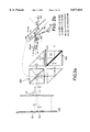
- FIG. 4 an embodiment of the system of the invention in which one microlens enables four picture elements in the screen to be illuminated
- FIGS. 5a to 5e means for producing the light polarization system using a cholesteric filter
- FIG. 6 an illumination system applying polarization devices, like that in FIG. 5e, as miniaturized multi-elements;
- FIG. 7 an embodiment of the system in FIG. 6;
- FIGS. 8a and 8b an illumination system which includes a holographic polarizing splitter device
- FIGS. 9a to 9c configurations of picture elements in the screen
- FIG. 10 a general arrangement of the system of the invention.
- FIGS. 11 and 12 examples of arrangements and of shapes of lenses for illuminating the liquid-crystal screen.
- FIGS. 1a, 1b, 2a and 2b One embodiment of the system of the invention will therefore be described with reference to FIGS. 1a, 1b, 2a and 2b.
- the light is split into two parts (beams F1 and F2) of complementary polarizations.
- One of the polarizations is rotated through ⁇ /2 by the use of, for example, a TN liquid-crystal cell.
- Two beams are recombined by the mirrors M1 and M2 or by total-reflection prisms at a double prism DPC. The latter combines the two beams F1 and F2 and provides an extended illumination with twice the light flux (except for Fresnel losses).
- the core of this system is the double prism DPC.
- the double prism DPC As shown in FIG. 1b, its operation is as follows: a total internal reflection takes place within the glass, at the glass/air dioptric interface for example, when the angle of incidence of the light becomes greater than the critical angle ⁇ c (equal to arcsin (1/n), n being the refractive index of the glass).
- ⁇ c critical angle
- n being the refractive index of the glass.
- Each beam, having an angle of incidence greater than ⁇ c on this surface is totally reflected. However, the beams having a low angle of incidence are transmitted (except for Fresnel losses) in the air or from the air to the glass because of the symmetry of propagation. It may therefore be seen that, depending on the directions of the beams F1, F2 supplied by the mirrors M1, M2, the beam F2 is transmitted by the double prism DPC and the beam F1 is reflected.
- the light is incident on the liquid-crystal display LCD via a matrix of microlenses ⁇ L.
- These microlenses may be spherical or cylindrical.
- One microlens covers at least two pixels. It is therefore designed to direct one beam to one pixel and the second to the other pixel.
- the beam F1 transmitted by the microlens ⁇ L1 illuminates the pixel EL1 and the beam F2 illuminates the pixel EL2. According to this method, all the light passes through the liquid-crystal display, hence optimum results.
- FIGS. 2a, 2b show a system according to the invention in which the rotatable mirrors are replaced by prisms. In this case, the inclination of the two glass/air dioptric interfaces in the plane of recombination causes no problem.
- FIGS. 3a and 3b show an example in which the glass (BK7) has an index of 1.5168.
- the light emitted by the double prism is not centred on the normal to the exit face of the double prism.
- each microlens enables four pixels to be illuminated.
- the system has two lenses SL1, SL2 receiving the two angularly split beams supplied by the beam splitting system described above. For example, these two beams are supplied by the double prism DPC in FIGS. 1a and 2a.
- the lens SL1 supplies two beams F3 and F4.
- the lens SL2 supplies two beams F5 and F6, these not being shown but being similar to the beams F3 and F4.
- These various beams are integrated by four relay lenses RL and a collecting lens CL so that each beam is superimposed on the surface of the matrix of microlenses ⁇ L. These various beams are incident on the ⁇ L surface at different angles of incidence.
- Each microlens ⁇ L1 focuses a beam onto a pixel EL1 to EL4.
- each microlens ⁇ L1 enables four pixels in the LCD screen to be illuminated.
- the light source may be extended in the direction of the largest dimension of the liquid-crystal display, for example along the 16 dimension for a 16 ⁇ 9 screen.
- the microlenses may be cylindrical (focusing along the 16 axis) or spherical. In the latter case, the gain in light flux is greater.
- the microlenses may be produced according to the prior art.
- the pixels may be arranged in rows and columns.
- Four pixels may be illuminated by a single microlens ⁇ L, according to the illumination system of FIG. 4, or else each group of two pixels may be illuminated by one microlens.
- the rows of pixels are offset with respect to one another.
- Each group of two pixels is illuminated by one microlens ⁇ L.
- microlenses with respect to the pixels so that each microlens illuminates several pixels. It is also possible, as shown in FIG. 12, to design the shape of the microlenses (for example a hexagonal shape) so that it matches the circular shape of the projection objective.
- FIGS. 5a and 5b show systems according to the invention in which the double prism DPC fulfills the functions of polarizing splitting, polarization rotation and recombination of the beams in the direction of the liquid-crystal screen.
- This system is based on the principle of total internal reflection for the purpose of combining the two beams.
- the unpolarized beam F is totally reflected by the first glass/air dioptric interface D1.
- 50% of the intensity of the beam is transmitted for the right-circular polarization (for example) and 50% is reflected by the cholesteric filter CF, and then becomes incident at the glass/air dioptric interface D1 with an angle of incidence of ⁇ 2 so that ⁇ 2 is less than this critical angle.
- the beam is transmitted as far as its reflection on the mirror M3 (metallized surface). On reflection, the direction of polarization is reversed, from right to left.
- This beam then passes through the glass/air dioptric interface D2 under the same conditions as those mentioned previously and passes through the cholesteric filter CF, since the polarization is now suitably oriented.
- the resultant light beams F1 and F2 make an angle ⁇ suitable for illuminating the liquid-crystal screen.
- FIG. 5c shows another polarizing conversion system based on cholesteric filters. It is advantageous to replace the mirror M3 by a retroreflector MR and a ⁇ /4 plate in order to orient the plane of polarization of the incident light.
- the (90 degree) retroreflector is practical since the incident light reflected on the retroreflector is parallel.
- FIG. 5d shows another polarizing conversion system based on the use of cholesteric filters.
- the unpolarized light is totally transmitted across two glass/air interfaces D1, D2.
- the beam is split into two parts--50% of the circularly polarized light is transmitted and the other part is reflected.
- the angle of incidence on the cholesteric filter CF is such that the reflected light is totally internally reflected at the glass/air interface.
- This beam is once again reflected on the mirror M3 (at a virtually zero angle of incidence), and has its polarization reversed, and is then reflected by the dioptric interface D2 onto the filter CF.
- the DPC device thus supplies two beams of the same polarization.
- the angle between the beams F1 and F2 arises from the fact that the filter CF is not perpendicular to the mirror M3.
- the cholesteric filter CF In order to obtain an angle between the beams F1, F2, provision is made in FIG. 5d for the cholesteric filter CF to be inclined with respect to the optical axis of the system (with respect to the beam F). Thus, the beam reflected by the filter CF is inclined with respect to the beam F and therefore with respect to F1. This inclination may be provided by means of an auxiliary prism P'1.
- FIG. 5e shows an alternative form of the system of FIG. 5d in which the two prisms P1 and P2 are not 45° isosceles triangles.
- the entry face A1 of the prism P2 makes an angle ⁇ of less than 45° with the hypotenuse of the prisms.
- One of the polarizations is transmitted as the beam F1 by the filter CF.
- the other polarization is reflected by the filter CF, the splitting dioptric interface of the two prisms and the mirror M3 in order to give the beam F2.
- the beam F2 then makes an angle with the beam F1. Because of critical angles of reflection at the interfaces between the prisms, the direction of the beam F may be inclined with respect to the face A1.
- This system may be applied to the projection system via two "large" prisms.
- it is possible to design quite a thin polarizing converter by forming a set of several small polarizing conversion systems, as shown in FIG. 6. In this way, we obtain the polarizing converter with a smaller thickness.
- the operating principle is identical to that already mentioned hereinabove, especially with regard to FIG. 5d (in this case the filter CF is inclined at an angle ⁇ with respect to the exit faces of the prisms) or with regard to FIG. 5e.
- the circularly polarized light (for example right-circularly polarized) is reflected.
- the total internal reflection introduces a phase shift of ⁇ between the s and p components.
- Reflection on the mirror M3 introduces a phase shift of ⁇ .
- the total phase shift is ⁇ .
- the right-circularly polarized light becomes left-circularly polarized light.
- miniaturized polarizing converter is fitted to the liquid-crystal display (with polarizer and analyzer), we avoid any losses and improve the light efficiency by a factor of 2;
- the prism system may be thin and easy to manufacture. It may be composed of a moulded transparent material (glass or acrylic).
- each tooth has, for example, a first face perpendicular to the plane of the plates and a second face inclined substantially at 45°.
- the first face is metallized to form the mirror M3.
- the cholesteric filter CF may be on the plane face of the plate P6.
- the prism system may be configured along two possible directions--one along the long side of the LCD display and the other along the short side.
- the system In the case of current AM-type LCD displays, in which the contrast is superior for the angle of illumination along the longer side of the LCD display, it is clear that the system must be installed along the direction of the short side of the liquid-crystal screen.
- FIG. 8a shows an alternative form in which the cholesteric filter is placed between the two common faces of the two prisms.
- the cholesteric filter may be replaced by an alternative system using a holographic element HOE.
- the holographic optical element consisting of a phase-volume diffracting element, may provide an effective optical function when it is produced in quite a thin film (a thickness of approximately 10 ⁇ m). These components are less expensive, lightweight and may be combined with another optical function.
- the polarizing splitting function is achieved by recording the interference patterns resulting from the interference of two coherent plane waves in a thin-film photosensitive material.
- the index variation (dn) induced in the material is large.
- the variations in the recording index enable a mirror function to be produced for one polarization component (45° Brewster conditions), the second polarization component being totally transmitted.
- FIG. 8b shows an embodiment of the device in FIG. 8a.
- the holographic splitter HOE is produced on a glass plate and adhesively bonded to the hypotenuse face of the prism P1 by the use of an index-matching substance.
- the prisms P1 and P2 are each produced from a single piece, with their faces M7, M8 metallized.
- This type of component is commonly employed for various colours (that is to say a limited bandwidth).
- This polarizing conversion system of the invention is therefore based on a very compact holographic optical polarizer.
- the latter may be used in a projection system for white light or for each colour.
- Unpolarized (white or monochrome) light is incident on the polarizer HOE.
- the light polarized in a direction "S" is totally reflected.
- the "p” component is transmitted twice at the HOE/air and air/glass boundaries. This "p” component is reflected by the inclined mirror M8 and then by the phenomenon of total internal reflection (TIR).
- TIR total internal reflection
- the "s"-type polarized beam becomes a "p"-type polarized beam.
- This beam again becomes incident on the polarizer HOE and is then totally transmitted--first of all by the HOE and then by the HOE/air and air/glass boundaries.
- the liquid-crystal screen therefore receives two main beams F1, F2 which are polarized in the same way, each being focused by the microlenses onto half of the pixels (onto each row, for example). Within each pixel, the focusing depends only on the illumination aperture of the lamp. The following is therefore in no way different, if the polarization system is disregarded.
- the focusing is slightly offset with respect to the axis
- p is the horizontal pitch of the liquid-crystal display (see FIG. 6a) and f is the focal length of each microlens in the thickness of the glass or of the liquid-crystal display.
- the recombiner will be able to act as an angle filter. This is because, if the polarizing converter is designed to obtain ⁇ ⁇ deg. in air, for example, and the value of the extent of the lamp varies (throughout its lifetime or after it has been changed), all the beams of angles greater than ⁇ will be transmitted for one arm only (no total internal reflection), and then reflected for the second arm and not transmitted in their entirety. In this way, the illumination box is an angle filter. We are thus able to use a more extended light source without affecting the contrast of the liquid-crystal display.
- the transmission coefficient of the ⁇ polarization-rotation plate is taken to be equal to 94%.
- the system of the invention has several advantages, namely:
- the system is optimal for the polarization and focusing converter
- this beam may be directly to illuminate the liquid-crystal display of a monovalve or monochrome projector (see FIG. 10) or for a three-valve system for trichrome projection.
- this system there is an illumination box supplying two beams as described above, the LCD screen and the array of microlenses ⁇ L.
Abstract
This system for illuminating a liquid-crystal screen comprises a light source which emits an unpolarized light beam (F). A polarizing splitter device (PBS) receives this unpolarized light beam and retransmits, onto the liquid-crystal screen, a first and a second beam (F1, F2) which are polarized in the same polarization direction. The axes of the two beams make a defined angle (2β) between them. A matrix of microlenses is provided with one microlens (μL) for at least two adjacent picture elements (EL1, EL2) in the liquid-crystal screen. Each microlens directs that part of the first beam which it receives onto one (EL1) of the two picture elements and that part of the second beam which it receives onto the other picture element (EL2).
Description
The invention relates to a system for illuminating a liquid-crystal screen and especially a system enabling the two polarizations of an unpolarized illumination source to be used effectively.
The emergence of liquid-crystal screen technology offers an excellent outlet for video projection techniques. The light emitted by an arc lamp is modulated by a liquid-crystal cell. The image formed by the liquid-crystal display device is projected by an optical system onto a screen. The so-called AM-TFT TNLCD technique (that is to say twisted-nematic liquid-crystal display controlled by an active matrix of thin-film transistors) is regarded as essential for liquid-crystal screens, each picture element (pixel) being controlled by a transistor. The light incident on the liquid-crystal screen must be linearly polarized. The major drawback of this technique is its low efficiency.
In fact, 1 to 2% of the light reaches the screen. Three main parameters limit this efficiency, namely:
1--more than 50% of the light is lost (-60%) since the light coming from the lamp is not polarized;
2--the filling factor of the cell is limited, especially for the definition of a large image and the small diameter of the liquid-crystal modulator. The filling factor or OAR (Open Aperture Ratio) is about 50%;
3--since the lamp is not small, the illumination of the small diameter of the LCD liquid-crystal display (the light beam being defined by the solid angle adapted to the contrast of the LCD display) decreases the light efficiency. Screens of 16:9 format have a light efficiency of less than 40%.
Other factors cause attenuation, such as colour rendition, white balancing and Fresnel losses.
Many solutions have been proposed to improve the light efficiency of these projection systems. Some solutions propose the conversion of the second polarization (see, for example, the document "Large Aperture Polarized Light Source and Novel Liquid Crystal Display Operating Modes" S. V. Belayev, M. Schadt, M. I. Bamik, J. Funufschilling, N. V. Malimoneko and K. Schmitt. Japanese Journal of Applied Physics, Vol. 29., April 1990, pp. L634-L637) in the illumination box, and others recommend the use of microlenses intended to concentrate the light in the active area of the pixels in the screen (see for example the document "Brightness Enhancement of an LCD Projection by Planar Microlens Array", H. Hamada, F. Funada, M. Hijikigawa and K. Awane, SID 92 DIGEST, pp. 269-272).
The invention relates to a high-performance polarizing converter which can be combined with conventional microlenses so as to obtain a high-efficiency projector, characterized by a performance which is superior, possibly by up to a factor of 3, compared to a conventional system.
In order to illustrate the various improvements made to the proposed systems, we have worked on the basis of the useful geometrical extent or analysis of the extent.
The value of the extent of a light beam through a surface S is the product of the area of the said surface multiplied by the solid angle defining the light beam:
E(mm2.sr)=S(circular area)×Ω
where:
Ω=2π 1-cos (β)!,
β being the illumination half-aperture.
The lamp used in the liquid-crystal projection display system has a spatial extension (that is to say a non-zero spatial extension); it may be characterized by its extent: Elamp or Flux (Flux=E (Extent)×(L (Luminance), if L is constant).
Moreover, the contrast of the LCD liquid-crystal display is largely dependent on the illumination aperture. If β<±10 deg., the contrast will be always acceptable for projection. Thus, Ω is limited to a value Ω1. The said limitation is also associated with the objective lens used for the projection.
Furthermore, liquid-crystal screens having quite a small diameter have been chosen so as to decrease the cost of the said systems and their optical components, resulting in a small illumination area S1.
If the product of S1×Ω1, that is to say E1, is less than Elamp, the light efficiency will be poor and equal to the ratio E1/Elamp.
If E1 is greater than Elamp, that is to say the light efficiency will be equal to 100%.
If E1 is equal to Elamp, the system will be satisfactorily optimized.
The polarizing conversion system doubles the value of the extent E since the light from the two polarization components is spatially split into two directions.
After having passed through the polarization splitter, the light E becomes 2E. At this stage, 2 cases may be considered:
2E=(2S)×Ω, which is not acceptable because of homogeneity and space problems;
2E=S×(2Ω)--the current techniques demonstrate that many systems do not achieve this minimum value (i.e. 2Ω), but higher than this.
Analysis of the extent may be applied to the method of focusing the light onto the pixels in the liquid-crystal screen. For conventional focusing using a matrix of spherical microlenses--one microlens for each pixel for 100% focusing--hence the need to obtain a filling factor of 100% and no longer 50% (or less); the reason for this is that the focusing area is less than or equal to the active area of the pixel, that is to say:
2f×tan (βglass)≦active area
where:
the active surface area of the pixel is equal to the pixel area less the area of the black matrix (masking matrix), i.e. size of the pixel--black matrix;
f is the thickness of the liquid-crystal screen; and
βglass is the illumination half-angle within the glass of the LCD display.
Knowing the parameters of the system--f, βglass, size and dimensions of the LCD display--it is thus possible to define the quantity of light passing through the screen after focusing:
Efocusing =S (circular area at the periphery of the LCD display)×2π 1-cos (n.βglass)!,
where n is the refractive index of the glass of the LCD display.
As mentioned previously, the total efficiency is the ratio of Efocusing to Elamp.
Conventional illumination systems provided with polarizing or focusing-based conversion devices cannot actually be used because of the extension of the value of extent, characteristic of the polarizing converter for example, thereby cancelling out the advantage of the focusing, even if the lamp has a restricted geometrical extent. The invention solves this problem and gives a gain of greater than 3 in the light flux.
Furthermore, extension of the solid angle Ω may be performed in various ways--either in the direction of the orifice or in another direction (horizontal or vertical with respect to the distribution of the isocontrast of the LCD display). Extension in the correct direction for the contrast of the screen is possible in this case.
The invention therefore relates to a system for illuminating a liquid-crystal screen, comprising a light source emitting an unpolarized light beam, a polarizing splitter device receiving this unpolarized light beam and retransmitting, onto the liquid-crystal screen, a first and a second beam which are polarized in the same polarization direction, the axes of the two beams making a defined angle, characterized in that it includes a matrix of microlenses with one microlens for two adjacent picture elements in the liquid-crystal screen, each microlens directing that part of the first beam which it receives onto one of the two picture elements and that part of the second beam which it receives onto the other picture element.
The various objects and characteristics of the invention will appear more clearly in the following description and in the appended figures which represent:
FIGS. 1a and 1b, a simplified embodiment of the system according to the invention;
FIGS. 2a and 2b, an alternative form of the system in FIGS. 1a and 1b;
FIGS. 3a and 3b, means for centering the light with respect to the normal to the plane of the screen;
FIG. 4, an embodiment of the system of the invention in which one microlens enables four picture elements in the screen to be illuminated;
FIGS. 5a to 5e, means for producing the light polarization system using a cholesteric filter;
FIG. 6, an illumination system applying polarization devices, like that in FIG. 5e, as miniaturized multi-elements;
FIG. 7, an embodiment of the system in FIG. 6;
FIGS. 8a and 8b, an illumination system which includes a holographic polarizing splitter device;
FIGS. 9a to 9c, configurations of picture elements in the screen;
FIG. 10, a general arrangement of the system of the invention;
FIGS. 11 and 12, examples of arrangements and of shapes of lenses for illuminating the liquid-crystal screen.
One embodiment of the system of the invention will therefore be described with reference to FIGS. 1a, 1b, 2a and 2b.
The light emitted by the arc lamp AL, inside a parabolic reflector for example, is incident on the polarizing splitter PBS (Polarizing Beam Splitter) having cholesteric filters or other polarization-sensitive components. The light is split into two parts (beams F1 and F2) of complementary polarizations. One of the polarizations is rotated through λ/2 by the use of, for example, a TN liquid-crystal cell. Two beams are recombined by the mirrors M1 and M2 or by total-reflection prisms at a double prism DPC. The latter combines the two beams F1 and F2 and provides an extended illumination with twice the light flux (except for Fresnel losses).
The core of this system is the double prism DPC. As shown in FIG. 1b, its operation is as follows: a total internal reflection takes place within the glass, at the glass/air dioptric interface for example, when the angle of incidence of the light becomes greater than the critical angle θc (equal to arcsin (1/n), n being the refractive index of the glass). Each beam, having an angle of incidence greater than θc on this surface, is totally reflected. However, the beams having a low angle of incidence are transmitted (except for Fresnel losses) in the air or from the air to the glass because of the symmetry of propagation. It may therefore be seen that, depending on the directions of the beams F1, F2 supplied by the mirrors M1, M2, the beam F2 is transmitted by the double prism DPC and the beam F1 is reflected.
The light is incident on the liquid-crystal display LCD via a matrix of microlenses μL. These microlenses may be spherical or cylindrical. One microlens covers at least two pixels. It is therefore designed to direct one beam to one pixel and the second to the other pixel. For example, the beam F1 transmitted by the microlens μL1 illuminates the pixel EL1 and the beam F2 illuminates the pixel EL2. According to this method, all the light passes through the liquid-crystal display, hence optimum results.
We actually obtain a wave 2Ω for a surface area of substantially 1S, meaning that we reach a minimum value of the extent.
FIGS. 2a, 2b show a system according to the invention in which the rotatable mirrors are replaced by prisms. In this case, the inclination of the two glass/air dioptric interfaces in the plane of recombination causes no problem.
We know that the light beam from the light source is not collimated, but rather has an illumination aperture of ±βair. Thus, for combining, the conditions relating to the critical angle βc and to the inclined angle should be satisfied (see FIGS. 1 and 2).
FIGS. 3a and 3b show an example in which the glass (BK7) has an index of 1.5168. The light emitted by the double prism is not centred on the normal to the exit face of the double prism. In this case, it is possible to illuminate the liquid-crystal screen directly (FIG. 3a) by inclining the latter or by providing an exit prism P3 (FIG. 3b) so as to refract the light beam and then to centre the light for illuminating the liquid-crystal screen.
In order to centre the emitted illumination, it is necessary to provide quite a low refractive index (n=1.4) for the double prism. However, this index is not absolutely essential and leads to high costs.
Referring to FIG. 4, an embodiment of the invention will now be described in which each microlens enables four pixels to be illuminated.
The system has two lenses SL1, SL2 receiving the two angularly split beams supplied by the beam splitting system described above. For example, these two beams are supplied by the double prism DPC in FIGS. 1a and 2a.
The lens SL1 supplies two beams F3 and F4. The lens SL2 supplies two beams F5 and F6, these not being shown but being similar to the beams F3 and F4. These various beams are integrated by four relay lenses RL and a collecting lens CL so that each beam is superimposed on the surface of the matrix of microlenses μL. These various beams are incident on the μL surface at different angles of incidence. Each microlens μL1 focuses a beam onto a pixel EL1 to EL4. Thus each microlens μL1 enables four pixels in the LCD screen to be illuminated.
According to the invention, the light source may be extended in the direction of the largest dimension of the liquid-crystal display, for example along the 16 dimension for a 16×9 screen. The microlenses may be cylindrical (focusing along the 16 axis) or spherical. In the latter case, the gain in light flux is greater. The microlenses may be produced according to the prior art.
There is no restriction with regard to the configuration of the pixels (FIGS. 9a to 9c). For example, according to FIG. 9b, the pixels may be arranged in rows and columns. Four pixels may be illuminated by a single microlens μL, according to the illumination system of FIG. 4, or else each group of two pixels may be illuminated by one microlens. According to FIG. 9c, the rows of pixels are offset with respect to one another. Each group of two pixels is illuminated by one microlens μL.
According to the embodiments in FIGS. 11 and 12, it is also possible to design arrangements of microlenses with respect to the pixels so that each microlens illuminates several pixels. It is also possible, as shown in FIG. 12, to design the shape of the microlenses (for example a hexagonal shape) so that it matches the circular shape of the projection objective.
We will now give examples of polarizing splitters or cholesteric filters used as polarization converter.
FIGS. 5a and 5b show systems according to the invention in which the double prism DPC fulfills the functions of polarizing splitting, polarization rotation and recombination of the beams in the direction of the liquid-crystal screen.
This system is based on the principle of total internal reflection for the purpose of combining the two beams. The unpolarized beam F is totally reflected by the first glass/air dioptric interface D1. 50% of the intensity of the beam is transmitted for the right-circular polarization (for example) and 50% is reflected by the cholesteric filter CF, and then becomes incident at the glass/air dioptric interface D1 with an angle of incidence of θ2 so that θ2 is less than this critical angle. Next, the beam is transmitted as far as its reflection on the mirror M3 (metallized surface). On reflection, the direction of polarization is reversed, from right to left. This beam then passes through the glass/air dioptric interface D2 under the same conditions as those mentioned previously and passes through the cholesteric filter CF, since the polarization is now suitably oriented. The resultant light beams F1 and F2 make an angle β suitable for illuminating the liquid-crystal screen.
It is also possible to provide only a single additional prism, for example P'1, as shown in FIG. 5b. It is then important for the plane of the cholesteric filter CF not to be parallel to the plane of the mirror M3.
FIG. 5c shows another polarizing conversion system based on cholesteric filters. It is advantageous to replace the mirror M3 by a retroreflector MR and a λ/4 plate in order to orient the plane of polarization of the incident light. The (90 degree) retroreflector is practical since the incident light reflected on the retroreflector is parallel.
FIG. 5d shows another polarizing conversion system based on the use of cholesteric filters. Compared to the previous figures, the unpolarized light is totally transmitted across two glass/air interfaces D1, D2. Next, the beam is split into two parts--50% of the circularly polarized light is transmitted and the other part is reflected. The angle of incidence on the cholesteric filter CF is such that the reflected light is totally internally reflected at the glass/air interface. This beam is once again reflected on the mirror M3 (at a virtually zero angle of incidence), and has its polarization reversed, and is then reflected by the dioptric interface D2 onto the filter CF. The DPC device thus supplies two beams of the same polarization. The angle between the beams F1 and F2 arises from the fact that the filter CF is not perpendicular to the mirror M3.
In order to obtain an angle between the beams F1, F2, provision is made in FIG. 5d for the cholesteric filter CF to be inclined with respect to the optical axis of the system (with respect to the beam F). Thus, the beam reflected by the filter CF is inclined with respect to the beam F and therefore with respect to F1. This inclination may be provided by means of an auxiliary prism P'1.
FIG. 5e shows an alternative form of the system of FIG. 5d in which the two prisms P1 and P2 are not 45° isosceles triangles. According to this figure, the entry face A1 of the prism P2 makes an angle β of less than 45° with the hypotenuse of the prisms. One of the polarizations is transmitted as the beam F1 by the filter CF. The other polarization is reflected by the filter CF, the splitting dioptric interface of the two prisms and the mirror M3 in order to give the beam F2. The beam F2 then makes an angle with the beam F1. Because of critical angles of reflection at the interfaces between the prisms, the direction of the beam F may be inclined with respect to the face A1.
This system may be applied to the projection system via two "large" prisms. However, it is possible to design quite a thin polarizing converter by forming a set of several small polarizing conversion systems, as shown in FIG. 6. In this way, we obtain the polarizing converter with a smaller thickness. The operating principle is identical to that already mentioned hereinabove, especially with regard to FIG. 5d (in this case the filter CF is inclined at an angle α with respect to the exit faces of the prisms) or with regard to FIG. 5e. The circularly polarized light (for example right-circularly polarized) is reflected.
The total internal reflection introduces a phase shift of δ between the s and p components.
Reflection on the mirror M3 introduces a phase shift of π.
Total internal reflection again introduces a phase shift, of -δ, between the s and p components.
Thus, the total phase shift is π. The right-circularly polarized light becomes left-circularly polarized light.
This miniaturized system has several advantages:
if the miniaturized polarizing converter is fitted to the liquid-crystal display (with polarizer and analyzer), we avoid any losses and improve the light efficiency by a factor of 2;
the prism system may be thin and easy to manufacture. It may be composed of a moulded transparent material (glass or acrylic).
To do this, two dentate plates P5, P6 (made of glass) are used, these having complementary shapes so as to form the prisms in FIG. 7. Each tooth has, for example, a first face perpendicular to the plane of the plates and a second face inclined substantially at 45°. The first face is metallized to form the mirror M3.
The cholesteric filter CF may be on the plane face of the plate P6.
Next, the two plates P5, P6 are fitted one inside the other.
The prism system may be configured along two possible directions--one along the long side of the LCD display and the other along the short side. In the case of current AM-type LCD displays, in which the contrast is superior for the angle of illumination along the longer side of the LCD display, it is clear that the system must be installed along the direction of the short side of the liquid-crystal screen.
FIG. 8a shows an alternative form in which the cholesteric filter is placed between the two common faces of the two prisms. In this alternative form, the cholesteric filter may be replaced by an alternative system using a holographic element HOE. The holographic optical element, consisting of a phase-volume diffracting element, may provide an effective optical function when it is produced in quite a thin film (a thickness of approximately 10 μm). These components are less expensive, lightweight and may be combined with another optical function.
The polarizing splitting function is achieved by recording the interference patterns resulting from the interference of two coherent plane waves in a thin-film photosensitive material. The index variation (dn) induced in the material is large. The variations in the recording index enable a mirror function to be produced for one polarization component (45° Brewster conditions), the second polarization component being totally transmitted.
FIG. 8b shows an embodiment of the device in FIG. 8a. The holographic splitter HOE is produced on a glass plate and adhesively bonded to the hypotenuse face of the prism P1 by the use of an index-matching substance. The prisms P1 and P2 are each produced from a single piece, with their faces M7, M8 metallized.
This type of component is commonly employed for various colours (that is to say a limited bandwidth).
This polarizing conversion system of the invention is therefore based on a very compact holographic optical polarizer. The latter may be used in a projection system for white light or for each colour.
Unpolarized (white or monochrome) light is incident on the polarizer HOE. The light polarized in a direction "S" is totally reflected. The perpendicularly polarized light "p" is not diffracted and passes through the polarizer HOE (fitted to the hypotenuse of the prism). Because of the angle of incidence, θ is less than the critical angle θc =arcsin (1/n)!. Next, the "p" component is transmitted twice at the HOE/air and air/glass boundaries. This "p" component is reflected by the inclined mirror M8 and then by the phenomenon of total internal reflection (TIR). The "s" component reflected by the polarizer HOE passes twice through a λ/4 plate and is reflected on the inclined mirror M7. Next, the "s"-type polarized beam becomes a "p"-type polarized beam. This beam again becomes incident on the polarizer HOE and is then totally transmitted--first of all by the HOE and then by the HOE/air and air/glass boundaries.
In this way, the light is totally polarized. This method has several advantages, namely:
the two optical paths are equal, and so there is no problem of uniformity when illuminating the LCD display;
by virtue of the holographic polarizing beam splitter currently used for each colour, it is possible to design a polarizing converter for each channel of a three-LCD system without excessively increasing the overall size of the projection system;
the p polarization passing through the glass/air and air/glass dioptric interfaces is virtually unattenuated, which reduces the Fresnel losses of the system to a minimum.
The liquid-crystal screen therefore receives two main beams F1, F2 which are polarized in the same way, each being focused by the microlenses onto half of the pixels (onto each row, for example). Within each pixel, the focusing depends only on the illumination aperture of the lamp. The following is therefore in no way different, if the polarization system is disregarded.
However, the optimum focusing conditions are as follows:
for each pixel, the focusing is slightly offset with respect to the axis;
to have an optimized system, it is therefore necessary to satisfy the condition below:
arctan (p/f)≧βglass
where p is the horizontal pitch of the liquid-crystal display (see FIG. 6a) and f is the focal length of each microlens in the thickness of the glass or of the liquid-crystal display.
If this condition is not met (for example if the pitch is too small or too large), it is possible to modify the thickness of the display.
If the illumination aperture β is too great, the recombiner will be able to act as an angle filter. This is because, if the polarizing converter is designed to obtain ± β deg. in air, for example, and the value of the extent of the lamp varies (throughout its lifetime or after it has been changed), all the beams of angles greater than β will be transmitted for one arm only (no total internal reflection), and then reflected for the second arm and not transmitted in their entirety. In this way, the illumination box is an angle filter. We are thus able to use a more extended light source without affecting the contrast of the liquid-crystal display.
The efficiency of such a polarizing converter, compared with a conventional system, is as follows:
Gain= R+T!/Tpolarizer
for a polarizing splitter (a conventional multilayer PBS) having a reflection coefficient R=0.99 and a transmission coefficient T=0.95, we have (FIG. 5a):
R=0.5×0.99×1×0.86×0.98=0.416
T=0.5×0.95×1×0.94×1×0.98=0.437
Gain= 0.416+0.437!/0.41≈2.1 without polarizer
Gain= 0.416+0.437!× 0.82/0.41!≈1.7 with polarizer;
for a cholesteric filter having R=0.96 and T=0.96 we have:
R= 0.86/2!×0.96×0.98×0.98×0.9=0.356
T= 0.86/2!×0.96×0.98×0.98=0.404
Gain= 0.356+0.440!× (0.82×0.93)/0.41!≈1.32 with polarizer.
The two calculations were performed on the basis of the following parameters:
antiglare coating coefficient of 0.98 both for the prisms and for the double prism;
total reflection coefficient, R=1;
transmission coefficient of the double prism, 0.86;
transmission coefficient of the polarizer, 0.41;
transmission coefficient of the analyzer, 0.82;
reflection coefficient of the mirror M3=0.9;
polarizability of the cholesteric filter=0.93; and
the transmission coefficient of the λ polarization-rotation plate is taken to be equal to 94%.
The system of the invention has several advantages, namely:
the system is optimal for the polarization and focusing converter;
the focusing along the horizontal axis does not alter the contrast values since the horizontally allowable angle of the liquid-crystal display is quite wide;
the p polarization passing through the glass/air and air/glass dioptric interfaces is hardly attenuated since it is "p". This limits the Fresnel losses of the system to a minimum.
At the exit of this system, we may use this beam directly to illuminate the liquid-crystal display of a monovalve or monochrome projector (see FIG. 10) or for a three-valve system for trichrome projection. In this system, there is an illumination box supplying two beams as described above, the LCD screen and the array of microlenses μL.
Claims (19)
1. System for illuminating a liquid-crystal screen, comprising a light source emitting an unpolarized light beam (F), a polarizing splitter device (PBS) receiving this unpolarized light beam and retransmitting, onto the liquid-crystal screen, a first and a second beam (F1, F2) which are complimentary polarized, emitted in the same direction, the axes of the two beams making a defined angle (dβ), characterized in that it includes a matrix of microlenses with one microlens (μL) for at least two adjacent picture elements (EL1, EL2) in the liquid-crystal screen, each microlens directing that part of the first beam which it receives onto one (EL1) of the two picture elements and that part of the second beam which it receives onto the other picture element (EL2).
2. System according to claim 1, characterized in that the screen (LCD) is in the focal plane of the microlenses (μL).
3. System according to claim 1, characterized in that the microlenses (μL) are spherical.
4. System according to claim 1, characterized in that the microlenses (μL) are cylindrical and each enables two rows of picture elements to be illuminated.
5. System according to claim 1, characterized in that the polarizing splitter device (PBS) includes a polarizing splitter which spatially splits the light from the source into two beams (F1, F2) which are polarized differently, at least one reflector (M1, M2) associated with a path of one beam (F1, F2), a beam recombiner (DPC) receiving the two beams and transmitting them to the screen (LCD).
6. System according to claim 5, characterized in that it includes two reflectors (M1, M2) each associated with the path of a beam (F1, F2).
7. System according to either of claims 5 and 6, characterized in that the reflectors (M1, M2) are rotatable.
8. System according to claim 5, characterized in that it includes a polarization-rotation (λ/2) device arranged in the path of one of the beams (F1 or F2).
9. System according to claim 1, characterized in that it includes:
a device for splitting the first beam into a third and fourth beam, and the second beam into a fifth and sixth beam; and
an integrator device (OI) for superimposing the four beams obtained on the matrix of microlenses (μL), each microlens (μL1) enabling the four beams to be transmitted separately to four pixels (EL1, EL2, EL3, EL4).
10. System according to claim 1, characterized in that the polarizing splitter includes a double prism having an entry face (A1) receiving the unpolarized light beam (F), a reflection face (A3), an exit face (A2) receiving the unpolarized light beam (F) transmitted via the double prism, a polarizing filter (CF), being associated with the exit face (A2), transmitting the light of a polarization type (F1) and reflecting the light of another polarization type onto the reflection face (A3) which reflects the light onto the exit face (A2) after polarization rotation.
11. System according to claim 10, characterized in that the polarizing filter (CF) makes an angle other than 90° with the direction of the unpolarized light beam.
12. System according to claim 10, characterized in that the double prism has an internal reflection face inclined substantially at 45° with respect to the entry and exit faces, the unpolarized light beam (F) having an angle of incidence (θ) on this face other than 45°.
13. System according to claim 10, characterized in that the reflection face includes a retroreflective mirror (RM).
14. System according to claim 10, characterized in that the reflection face includes a λ/4 polarization-rotation device.
15. System according to claim 10, characterized in that the entry face and the exit face are two opposite faces of the double prism and in that one of the prisms carries the polarizing filter (CF) on one of two of these adjacent faces and a reflective surface (M3) on the other.
16. System according to claim 15, characterized in that it includes a series of juxtaposed double prisms, the entry faces of the various double prisms lying in the same first plane and the exit faces of the various double prisms lying in the same second plane.
17. System according to claim 16, characterized in that it includes two dentate transparent plates (P5, P6) fitted one into the other by their teeth, each tooth having a face perpendicular to the plane of the plate and an inclined face, the perpendicular faces of one of the plates at least being reflective.
18. System according to claim 17, characterized in that a plane face of one plate (P6) opposite the dentate face is provided with a polarizing filter.
19. System according to claim 1, characterized in that the polarizing splitter (PBS) includes a double prism having a first entry face receiving the unpolarized light beam (F), a second face opposite this entry face and having reflection means (M8), a third face, adjacent to the first and second faces, possessing reflection means (M7) and in that, between the two half-prisms, a layer of photosensitive material is provided in which a hologram is recorded, enabling a light polarized in a first direction to be reflected and enabling a light polarized in a second direction, perpendicular to the first direction, to be transmitted.
Applications Claiming Priority (2)
| Application Number | Priority Date | Filing Date | Title |
|---|---|---|---|
| FR9505113 | 1995-04-28 | ||
| FR9505113A FR2733619B1 (en) | 1995-04-28 | 1995-04-28 | LIGHTING SYSTEM FOR A LIQUID CRYSTAL SCREEN |
Publications (1)
| Publication Number | Publication Date |
|---|---|
| US5877824A true US5877824A (en) | 1999-03-02 |
Family
ID=9478535
Family Applications (1)
| Application Number | Title | Priority Date | Filing Date |
|---|---|---|---|
| US08/633,242 Expired - Fee Related US5877824A (en) | 1995-04-28 | 1996-04-16 | System for illuminating a liquid-crystal screen |
Country Status (6)
| Country | Link |
|---|---|
| US (1) | US5877824A (en) |
| EP (1) | EP0740476B1 (en) |
| JP (1) | JP3657347B2 (en) |
| DE (1) | DE69610734T2 (en) |
| FR (1) | FR2733619B1 (en) |
| ZA (1) | ZA963007B (en) |
Cited By (10)
| Publication number | Priority date | Publication date | Assignee | Title |
|---|---|---|---|---|
| US6023370A (en) * | 1998-05-29 | 2000-02-08 | Primax Electronics Ltd. | Light polarizing device for generating a polarized light with different polarizations |
| US6388718B1 (en) * | 1998-11-13 | 2002-05-14 | Industrial Technology Research Institute | LCD projector of two-plate type |
| US20020080287A1 (en) * | 2000-12-22 | 2002-06-27 | Samsung Electro-Mechanics Co., Ltd. | Color separating/synthesizing apparatus |
| US6504589B1 (en) * | 1997-02-18 | 2003-01-07 | Dai Nippon Printing Co., Ltd. | Backlight device and liquid crystal display device |
| US20050013005A1 (en) * | 2003-05-22 | 2005-01-20 | Rogers John R. | Optical combiner designs and head mounted displays |
| US20050018309A1 (en) * | 2003-05-22 | 2005-01-27 | Mcguire James R. | Apparatus and methods for illuminating optical systems |
| US20060250696A1 (en) * | 2005-05-03 | 2006-11-09 | Mcguire James P | Head mounted display devices |
| US20070071932A1 (en) * | 2005-09-26 | 2007-03-29 | Kejian Huang | Retroreflective sheeting |
| US20070252954A1 (en) * | 2003-05-22 | 2007-11-01 | Mcguire James P Jr | Beamsplitting structures and methods in optical systems |
| US7542209B2 (en) | 2004-09-01 | 2009-06-02 | Optical Research Associates | Compact head mounted display devices with tilted/decentered lens element |
Families Citing this family (2)
| Publication number | Priority date | Publication date | Assignee | Title |
|---|---|---|---|---|
| EP1818696A3 (en) * | 2000-01-28 | 2007-08-22 | Seiko Epson Corporation | Projector with fine structured birefringent polarizer inclined to the projector axis |
| KR101403761B1 (en) * | 2013-01-08 | 2014-06-03 | 김재희 | Apparatus and method for projection of stereoscopic images |
Citations (8)
| Publication number | Priority date | Publication date | Assignee | Title |
|---|---|---|---|---|
| US4769750A (en) * | 1985-10-18 | 1988-09-06 | Nippon Kogaku K. K. | Illumination optical system |
| EP0395156A1 (en) * | 1989-04-28 | 1990-10-31 | Koninklijke Philips Electronics N.V. | Optical illumination system and projection apparatus comprising such a system |
| EP0512893A1 (en) * | 1991-05-07 | 1992-11-11 | Thomson-Csf | Illuminator for projector |
| EP0563874A1 (en) * | 1992-03-31 | 1993-10-06 | Matsushita Electric Industrial Co., Ltd. | Optical illumination system and projection display apparatus using the same |
| WO1995000865A1 (en) * | 1993-06-17 | 1995-01-05 | Xmr, Inc. | Improved optical beam integration system |
| US5506701A (en) * | 1993-01-28 | 1996-04-09 | Dai Nippon Printing Co., Ltd. | Hologram color filter, liquid crystal display device using the same, and fabrication process of hologram color filter |
| US5548349A (en) * | 1993-12-27 | 1996-08-20 | Sharp Kabushiki Kaisha | Transmission type color liquid display apparatus with first and second lens layers located between a white light source and the display device |
| US5737113A (en) * | 1995-08-04 | 1998-04-07 | Canon Kabushiki Kaisha | Optical modulators and color image display device employing the same |
Family Cites Families (4)
| Publication number | Priority date | Publication date | Assignee | Title |
|---|---|---|---|---|
| JPH05100331A (en) * | 1991-10-11 | 1993-04-23 | Toshiba Corp | Liquid crystal display device |
| JPH05196892A (en) * | 1992-01-21 | 1993-08-06 | Canon Inc | Polarized light illumination device and projection type display device using the same |
| US5430562A (en) * | 1993-01-25 | 1995-07-04 | Matsushita Electric Industrial Co., Ltd. | Liquid crystal light valve including between light and light valve microlenses and two reflecting layers with a matrix of openings |
| DE4307178C2 (en) * | 1993-03-08 | 1996-09-19 | Lueder Ernst | Device and method for polarizing light |
-
1995
- 1995-04-28 FR FR9505113A patent/FR2733619B1/en not_active Expired - Fee Related
-
1996
- 1996-04-16 ZA ZA963007A patent/ZA963007B/en unknown
- 1996-04-16 US US08/633,242 patent/US5877824A/en not_active Expired - Fee Related
- 1996-04-24 DE DE69610734T patent/DE69610734T2/en not_active Expired - Fee Related
- 1996-04-24 EP EP96400876A patent/EP0740476B1/en not_active Expired - Lifetime
- 1996-04-30 JP JP10889296A patent/JP3657347B2/en not_active Expired - Fee Related
Patent Citations (8)
| Publication number | Priority date | Publication date | Assignee | Title |
|---|---|---|---|---|
| US4769750A (en) * | 1985-10-18 | 1988-09-06 | Nippon Kogaku K. K. | Illumination optical system |
| EP0395156A1 (en) * | 1989-04-28 | 1990-10-31 | Koninklijke Philips Electronics N.V. | Optical illumination system and projection apparatus comprising such a system |
| EP0512893A1 (en) * | 1991-05-07 | 1992-11-11 | Thomson-Csf | Illuminator for projector |
| EP0563874A1 (en) * | 1992-03-31 | 1993-10-06 | Matsushita Electric Industrial Co., Ltd. | Optical illumination system and projection display apparatus using the same |
| US5506701A (en) * | 1993-01-28 | 1996-04-09 | Dai Nippon Printing Co., Ltd. | Hologram color filter, liquid crystal display device using the same, and fabrication process of hologram color filter |
| WO1995000865A1 (en) * | 1993-06-17 | 1995-01-05 | Xmr, Inc. | Improved optical beam integration system |
| US5548349A (en) * | 1993-12-27 | 1996-08-20 | Sharp Kabushiki Kaisha | Transmission type color liquid display apparatus with first and second lens layers located between a white light source and the display device |
| US5737113A (en) * | 1995-08-04 | 1998-04-07 | Canon Kabushiki Kaisha | Optical modulators and color image display device employing the same |
Non-Patent Citations (3)
| Title |
|---|
| Copy of European Search Report. * |
| Optical Engineering, vol. 32, No. 11, Nov. 1993, Bellingham US pp. 2665 2670 E.A. Watson Analysis Of Beam Steering With Decentered Microlens Arrays . * |
| Optical Engineering, vol. 32, No. 11, Nov. 1993, Bellingham US pp. 2665-2670 E.A. Watson "Analysis Of Beam Steering With Decentered Microlens Arrays". |
Cited By (17)
| Publication number | Priority date | Publication date | Assignee | Title |
|---|---|---|---|---|
| US6504589B1 (en) * | 1997-02-18 | 2003-01-07 | Dai Nippon Printing Co., Ltd. | Backlight device and liquid crystal display device |
| US20030095400A1 (en) * | 1997-02-18 | 2003-05-22 | Dai Nippon Printing Co., Ltd. | Backlight device for liquid crystal display, having polarization ligh splitter and light guide with light diffusing surface, and liquid crystal display device |
| US6023370A (en) * | 1998-05-29 | 2000-02-08 | Primax Electronics Ltd. | Light polarizing device for generating a polarized light with different polarizations |
| US6388718B1 (en) * | 1998-11-13 | 2002-05-14 | Industrial Technology Research Institute | LCD projector of two-plate type |
| US20020080287A1 (en) * | 2000-12-22 | 2002-06-27 | Samsung Electro-Mechanics Co., Ltd. | Color separating/synthesizing apparatus |
| US6678015B2 (en) * | 2000-12-22 | 2004-01-13 | Samsung Electro-Mechanics Co., Ltd. | Color separating/synthesizing apparatus |
| US20070252954A1 (en) * | 2003-05-22 | 2007-11-01 | Mcguire James P Jr | Beamsplitting structures and methods in optical systems |
| US20050018309A1 (en) * | 2003-05-22 | 2005-01-27 | Mcguire James R. | Apparatus and methods for illuminating optical systems |
| US7196849B2 (en) * | 2003-05-22 | 2007-03-27 | Optical Research Associates | Apparatus and methods for illuminating optical systems |
| US7230766B2 (en) | 2003-05-22 | 2007-06-12 | Optical Research Associates | Optical combiner designs and head mounted displays |
| US20050013005A1 (en) * | 2003-05-22 | 2005-01-20 | Rogers John R. | Optical combiner designs and head mounted displays |
| US7360899B2 (en) | 2003-05-22 | 2008-04-22 | Optical Research Associates | Beamsplitting structures and methods in optical systems |
| US7542209B2 (en) | 2004-09-01 | 2009-06-02 | Optical Research Associates | Compact head mounted display devices with tilted/decentered lens element |
| US20060250696A1 (en) * | 2005-05-03 | 2006-11-09 | Mcguire James P | Head mounted display devices |
| US7450310B2 (en) | 2005-05-03 | 2008-11-11 | Optical Research Associates | Head mounted display devices |
| US20070071932A1 (en) * | 2005-09-26 | 2007-03-29 | Kejian Huang | Retroreflective sheeting |
| US8268435B2 (en) | 2005-09-26 | 2012-09-18 | Avery Dennison Corporation | Retroreflective sheeting |
Also Published As
| Publication number | Publication date |
|---|---|
| EP0740476B1 (en) | 2000-10-25 |
| ZA963007B (en) | 1996-08-28 |
| EP0740476A1 (en) | 1996-10-30 |
| DE69610734T2 (en) | 2001-05-23 |
| FR2733619A1 (en) | 1996-10-31 |
| JPH095699A (en) | 1997-01-10 |
| JP3657347B2 (en) | 2005-06-08 |
| FR2733619B1 (en) | 1997-06-27 |
| DE69610734D1 (en) | 2000-11-30 |
Similar Documents
| Publication | Publication Date | Title |
|---|---|---|
| US5896232A (en) | Highly efficient and compact frontlighting for polarization-based reflection light valves | |
| US5737124A (en) | Polarizing splitter device and application to a system for illuminating a liquid-crystal screen | |
| EP0659024B1 (en) | Illumination system for a colour image projection device and circular polarizer suitable for use in such a system | |
| US5486884A (en) | Reflecting image projection screen and image projection system comprising such a screen | |
| US5327270A (en) | Polarizing beam splitter apparatus and light valve image projection system | |
| CA2058514C (en) | Polarization illumination device and projector having the same | |
| US5181054A (en) | Device for the projection of images using two orthogonal components of light polarization | |
| US5658060A (en) | Arrangement for projection displays employing reflective light valves | |
| US6923544B2 (en) | Projector | |
| EP0457605B1 (en) | Polarization converting device and polarized-light illuminating system using the device and image display unit using the device | |
| US5184248A (en) | Image projection apparatus | |
| US5446510A (en) | Image display apparatus | |
| US5601351A (en) | High-efficiency illumination device and image projection apparatus comprising such a device | |
| US5573324A (en) | Image projection system | |
| EP0552725A1 (en) | Polarization illumination apparatus and projector using the apparatus | |
| US5381197A (en) | Reflecting illumination projecting device | |
| US5299036A (en) | Liquid crystal projector including a polaration rotating element | |
| JPH02149882A (en) | Image projector | |
| EP0467447B1 (en) | Image projection apparatus | |
| KR20050085500A (en) | Image display apparatus | |
| US5235444A (en) | Image projection arrangement | |
| US5877824A (en) | System for illuminating a liquid-crystal screen | |
| US6142633A (en) | Polarized light illuminator and projection type image display apparatus | |
| US6290358B1 (en) | Polarized-light converting optical system, a polarized-light converting elemental device, a polarized-light converting elemental device array and a projection-type display device using any one of those components | |
| US5900973A (en) | Optical polarization device and projection system of liquid crystal valve type utilizing such a device |
Legal Events
| Date | Code | Title | Description |
|---|---|---|---|
| AS | Assignment |
Owner name: THOMSON MULTIMEDIA S.A., FRANCE Free format text: ASSIGNMENT OF ASSIGNORS INTEREST;ASSIGNOR:SARAYEDDINE, KHALED;REEL/FRAME:008149/0799 Effective date: 19960904 |
|
| FPAY | Fee payment |
Year of fee payment: 4 |
|
| REMI | Maintenance fee reminder mailed | ||
| LAPS | Lapse for failure to pay maintenance fees | ||
| STCH | Information on status: patent discontinuation |
Free format text: PATENT EXPIRED DUE TO NONPAYMENT OF MAINTENANCE FEES UNDER 37 CFR 1.362 |
|
| FP | Lapsed due to failure to pay maintenance fee |
Effective date: 20070302 |