US4902116A - Helmet display systems - Google Patents
Helmet display systems Download PDFInfo
- Publication number
- US4902116A US4902116A US07/199,537 US19953788A US4902116A US 4902116 A US4902116 A US 4902116A US 19953788 A US19953788 A US 19953788A US 4902116 A US4902116 A US 4902116A
- Authority
- US
- United States
- Prior art keywords
- eyepieces
- rays
- helmet
- eyepiece
- light transmissive
- Prior art date
- Legal status (The legal status is an assumption and is not a legal conclusion. Google has not performed a legal analysis and makes no representation as to the accuracy of the status listed.)
- Expired - Fee Related
Links
Images


Classifications
-
- G—PHYSICS
- G02—OPTICS
- G02B—OPTICAL ELEMENTS, SYSTEMS OR APPARATUS
- G02B27/00—Optical systems or apparatus not provided for by any of the groups G02B1/00 - G02B26/00, G02B30/00
- G02B27/01—Head-up displays
- G02B27/017—Head mounted
-
- A—HUMAN NECESSITIES
- A42—HEADWEAR
- A42B—HATS; HEAD COVERINGS
- A42B3/00—Helmets; Helmet covers ; Other protective head coverings
- A42B3/04—Parts, details or accessories of helmets
- A42B3/0406—Accessories for helmets
- A42B3/042—Optical devices
-
- G—PHYSICS
- G02—OPTICS
- G02B—OPTICAL ELEMENTS, SYSTEMS OR APPARATUS
- G02B27/00—Optical systems or apparatus not provided for by any of the groups G02B1/00 - G02B26/00, G02B30/00
- G02B27/01—Head-up displays
- G02B27/017—Head mounted
- G02B27/0172—Head mounted characterised by optical features
-
- G—PHYSICS
- G02—OPTICS
- G02B—OPTICAL ELEMENTS, SYSTEMS OR APPARATUS
- G02B27/00—Optical systems or apparatus not provided for by any of the groups G02B1/00 - G02B26/00, G02B30/00
- G02B27/01—Head-up displays
- G02B27/0101—Head-up displays characterised by optical features
- G02B2027/0132—Head-up displays characterised by optical features comprising binocular systems
- G02B2027/0136—Head-up displays characterised by optical features comprising binocular systems with a single image source for both eyes
Definitions
- This invention relates to helmet display systems.
- the invention relates to helmet display systems of the kind adapted to present, when supported on a helmet, a display of bright data to a wearer of the helmet superimposed on the wearer's view of the forward scene.
- a problem with bi-ocular display systems of the above kind is that the display arrangement of the system tends to obstruct the helmet wearer's field of view, particularly the upward field of view.
- a helmet display system including a display arrangement comprising: right and left collimating eyepieces; and projector means which in operation projects bright data for reflection by the right and left eyepieces to respective right and left eye positions; each eyepiece comprising first and second light transmissive/light reflective laminar elements defining a generally downwardly tapering space and defining at a position adjacent the wider end of the tapering space a principal focal plane of the eyepiece which is coincident with a respective one of two image planes formed by the projector means, and each eyepiece being supported at a respective one of two ports of a housing arrangement containing light paths leading from a bright data source of the projector means to the eyepieces by way of an optical system of the projector means including a relay lens and reflective elements serving in operation to direct rays from the bright data source so as to form images at the said two image planes; and wherein at at least one of the said ports of the housing arrangement, there is a light transmissive portion of the housing, the lower edge of which is
- the optical system includes a partially light transmissive, partially light reflective first planar element positioned substantially midway between and above said eyepieces onto which rays for both said eye pieces are directed from said source via a common path, said first element serving to split said rays between a first path which includes a reflective second planar element parallel to said first element to direct the rays through substantially 90 degrees and thence downwardly to the one of the said ports at which said transmissive portion is located and a second path which includes reflective third and fourth planar elements in parallel spaced relation in planes at right angles to the plane of said first element to direct the rays through two successive turns of substantially 90 degrees in the opposite sense and thence downwardly to the other one of said ports.
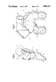
- FIG. 1 is a diagrammatic view of the helmet display system from one side
- FIG. 2 is a diagrammatic internal view of the display arrangement of the helmet display system of FIG. 1;
- FIG. 3 is a partly sectional diagrammatic internal view of the display arrangement illustrating a housing of the display arrangement
- FIG. 4 is a front view of the display arrangement
- FIG. 5 is a view from the right side of the display arrangement
- FIG. 6 is a view from the left side of the display arrangement.
- FIG. 7 is a rear view of the display arrangement.
- the helmet display system comprises a helmet body 1, a helmet visor 3 and a display arrangement 5 mounted on the helmet body 1 so as to lie between the body 1 and the visor 3.
- the display arrangement 5 comprises right and left collimating eyepieces 7,9 and projector means 11 which in operation projects bright data for reflection by the right and left eyepieces 7,9 to respective right and left eye positions 13,15 defined by the helmet body 1.
- the user 17 of the helmet display system viewing through the eye pieces 7,9, is thus presented with a display of bright data superimposed on his view of the forward scene through the eyepieces 7,9.
- Each eyepiece 7,9 comprises forward and rear light transmissive/light reflective laminar elements 19,21 defining therebetween a generally downwardly tapering space 23 and defining at a position adjacent the wider end of the tapering space 23 a principal focal plane 25 of the eyepiece 7,9, the principal focal plane 25 of each eyepiece 7,9 being arranged to be co-incident with a respective one of two image planes 25 formed by the projector means 11.
- Each eyepiece 7,9 is supported at a respective one of two ports 27,29 of a housing arrangement 31 for the projector means 11 and which contains light paths leading from a bright data source 33, in the form of a cathode ray tube, of the projector means 11 to the eyepieces 7,9 by way of an optical system 35 of the projector means 11.
- the optical system 35 serves in operation to direct rays from the bright data source 33 so as to form images at the two image planes 25.
- a clear light transmissive rectangular laminar portion 34 of the housing arrangement 31 At the right port 27 of the housing arrangement 31 there is a clear light transmissive rectangular laminar portion 34 of the housing arrangement 31, the lower edge 36 of which is contiguous with the upper edge 36 of the forward light transmissive/light reflective laminar element 19 of the right eyepieces 7 at that port 27.
- the portion 34 is suitably formed integrally with the element 19 with which it is contiguous. As best seen in FIG. 5, the provision of the portion 34 extends upwardly the angular range of the field of view available from the right eye position 13 through element 21.
- the optical system 35 comprises a partially light transmissive, partially light reflective first planar element 37 positioned substantially midway between and above the eyepieces 7,9 and onto which rays for both eyepieces 7,9 are directed via a common path 39 from the source 33 so as to be incident on the first element 37 in a direction substantially parallel to a straight line joining the eyepieces 7,9.
- the element 37 splits the rays incident thereon between transmission along a first path 41 and reflection along a second path 43.
- the first path 41 includes a reflective second planar element 45 which is parallel to the first element 37 and folds the rays through 90 degrees and thence to the right port 27, at which the portion 34 is located, to form an image at the right one of the two image planes 25.
- the second path 43 includes reflective third and fourth planar elements 47,49 in parallel spaced relation in planes at right angles to the plane of the first element 37 which folds the rays through two successive turns of 90 degrees in the opposite sense and thence to the left port 29 to form an image at the left one of the two image planes 25. It is to be noted that it is the arrangement of the elements of the optical system 35, in particular the configuration of the first and second paths 41,43, which allows the incorporation of the light transmissive portion 34 in the housing arrangement 31 to extend upwardly the field of view.
- the common path 39 includes reflection means in the form of reflective fifth and sixth planar elements 51,53 in spaced relation, the plane of the sixth element 53 being parallel to the plane of the first element 37 and the plane of the fifth element 51 being at 90 degrees to the plane of the sixth element 53.
- the fifth and sixth elements 51,53 folds rays from the source 33 through two successive turns of 90 degrees in the same sense and thence to incidence on the first element 37.
- the common path 39 also includes a Petzval relay lens comprising first and second parts 55,57, the first part 55 being located between the source 33 and the fifth element 51, the second part 57 being located between the sixth element 53 and the first element 37.
- the various items of the projector means 11 are all supported by the housing arrangement 31 within passages in the housing arrangement 31.
Abstract
Description
Claims (6)
Applications Claiming Priority (2)
| Application Number | Priority Date | Filing Date | Title |
|---|---|---|---|
| GB8713021 | 1987-06-03 | ||
| GB878713021A GB8713021D0 (en) | 1987-06-03 | 1987-06-03 | Helmet display systems |
Publications (1)
| Publication Number | Publication Date |
|---|---|
| US4902116A true US4902116A (en) | 1990-02-20 |
Family
ID=10618324
Family Applications (1)
| Application Number | Title | Priority Date | Filing Date |
|---|---|---|---|
| US07/199,537 Expired - Fee Related US4902116A (en) | 1987-06-03 | 1988-05-27 | Helmet display systems |
Country Status (3)
| Country | Link |
|---|---|
| US (1) | US4902116A (en) |
| GB (2) | GB8713021D0 (en) |
| IL (1) | IL86593A (en) |
Cited By (31)
| Publication number | Priority date | Publication date | Assignee | Title |
|---|---|---|---|---|
| US4969724A (en) * | 1988-10-27 | 1990-11-13 | Gec-Marconi Limited | Helmet supported optical systems with four reflections |
| US4988976A (en) * | 1989-09-06 | 1991-01-29 | Lu Hsing Tseng | Head-up display with magnetic field speed detecting means |
| US5134521A (en) * | 1990-06-01 | 1992-07-28 | Thomson-Csf | Wide-angle display device for compact simulator |
| US5184250A (en) * | 1990-06-01 | 1993-02-02 | Thomson-Csf | Device for the display of simulated images for helmets |
| US5245472A (en) * | 1991-06-26 | 1993-09-14 | Hughes Aircraft Company | High-efficiency, low-glare X-prism |
| EP0579506A1 (en) * | 1992-07-17 | 1994-01-19 | KAISER AEROSPACE & ELECTRONICS CORPORATION | Helmet-mounted biocular display system |
| US5321416A (en) * | 1992-07-27 | 1994-06-14 | Virtual Research Systems | Head-mounted visual display apparatus |
| US5526022A (en) | 1993-01-06 | 1996-06-11 | Virtual I/O, Inc. | Sourceless orientation sensor |
| US5619377A (en) * | 1992-02-07 | 1997-04-08 | Virtual I/O, Inc. | Optically corrected helmet mounted display |
| US5757546A (en) * | 1993-12-03 | 1998-05-26 | Stereographics Corporation | Electronic stereoscopic viewer |
| US5764417A (en) * | 1993-06-11 | 1998-06-09 | Sextant Avionique | Compact optical device for night vision and its application to goggles |
| US5767820A (en) * | 1995-05-09 | 1998-06-16 | Virtual Research Systems | Head-mounted visual display apparatus |
| US5861994A (en) * | 1994-11-04 | 1999-01-19 | Kelly; Shawn L. | Modular binocular electronic imaging system |
| US5864326A (en) * | 1992-02-07 | 1999-01-26 | I-O Display Systems Llc | Depixelated visual display |
| US5903396A (en) * | 1997-10-17 | 1999-05-11 | I/O Display Systems, Llc | Intensified visual display |
| US5903395A (en) * | 1994-08-31 | 1999-05-11 | I-O Display Systems Llc | Personal visual display system |
| US5991087A (en) * | 1993-11-12 | 1999-11-23 | I-O Display System Llc | Non-orthogonal plate in a virtual reality or heads up display |
| US5991085A (en) | 1995-04-21 | 1999-11-23 | I-O Display Systems Llc | Head-mounted personal visual display apparatus with image generator and holder |
| US6097543A (en) * | 1992-02-07 | 2000-08-01 | I-O Display Systems Llc | Personal visual display |
| US6160666A (en) * | 1994-02-07 | 2000-12-12 | I-O Display Systems Llc | Personal visual display system |
| US6195206B1 (en) | 1998-01-13 | 2001-02-27 | Elbit Systems Ltd. | Optical system for day and night use |
| US6239908B1 (en) | 1998-11-12 | 2001-05-29 | Shawn L. Kelly | Compact binocular imaging system using a single display |
| US6483646B2 (en) | 2000-08-16 | 2002-11-19 | Thomas P. Scott | Detachable monocular display |
| US20040061831A1 (en) * | 2002-09-27 | 2004-04-01 | The Boeing Company | Gaze tracking system, eye-tracking assembly and an associated method of calibration |
| US9451802B2 (en) | 2014-08-08 | 2016-09-27 | Fusar Technologies, Inc. | Helmet system and methods |
| US9500868B2 (en) | 2014-07-10 | 2016-11-22 | Honeywell International Inc. | Space suit helmet display system |
| WO2016187064A1 (en) | 2015-05-15 | 2016-11-24 | Vertical Optics, LLC | Wearable vision redirecting devices |
| US9690119B2 (en) | 2015-05-15 | 2017-06-27 | Vertical Optics, LLC | Wearable vision redirecting devices |
| US9848127B2 (en) | 2015-07-14 | 2017-12-19 | Honeywell International Inc. | System and method for a compact display |
| US11528393B2 (en) | 2016-02-23 | 2022-12-13 | Vertical Optics, Inc. | Wearable systems having remotely positioned vision redirection |
| US11567323B2 (en) * | 2019-12-01 | 2023-01-31 | Vision Products, Llc | Partial electronic see-through head-mounted display |
Families Citing this family (4)
| Publication number | Priority date | Publication date | Assignee | Title |
|---|---|---|---|---|
| US5081542A (en) * | 1989-12-12 | 1992-01-14 | Hughes Aircraft Company | Liquid crystal light valve goggles for eye protection |
| GB2247756A (en) * | 1990-09-08 | 1992-03-11 | British Aerospace | Helmut-moulded display |
| DE69221987T2 (en) * | 1991-11-01 | 1998-02-05 | Sega Enterprises Kk | Imaging device attached to the head |
| US6023288A (en) * | 1993-03-31 | 2000-02-08 | Cairns & Brother Inc. | Combination head-protective helmet and thermal imaging apparatus |
Citations (12)
| Publication number | Priority date | Publication date | Assignee | Title |
|---|---|---|---|---|
| US3059519A (en) * | 1956-09-05 | 1962-10-23 | Austin N Stanton | Headgear mounted cathode ray tube and binocular viewing device |
| US3205303A (en) * | 1961-03-27 | 1965-09-07 | Philco Corp | Remotely controlled remote viewing system |
| US3923370A (en) * | 1974-10-15 | 1975-12-02 | Honeywell Inc | Head mounted displays |
| US4081209A (en) * | 1975-04-29 | 1978-03-28 | Elliott Brothers (London) Limited | Headgear with spherical semi-reflecting surface |
| US4232943A (en) * | 1975-09-13 | 1980-11-11 | Pilkington P. E. Limited | Modified Petzval lens |
| US4269476A (en) * | 1978-11-07 | 1981-05-26 | Thomson-Csf | Helmet-mounted display system |
| US4361384A (en) * | 1980-06-27 | 1982-11-30 | The United States Of America As Represented By The Secretary Of The Army | High luminance miniature display |
| US4563061A (en) * | 1983-08-03 | 1986-01-07 | Marconi Avionics Limited | Night vision viewing systems |
| US4600271A (en) * | 1983-03-07 | 1986-07-15 | Thomson Csf | Head-up display |
| EP0202987A1 (en) * | 1985-05-03 | 1986-11-26 | Thomson-Csf | Apparatus for the transport and combination of optical images, and its use in a helmet-mounted sighting instrument |
| US4722101A (en) * | 1985-08-21 | 1988-02-02 | Blower David H | Optical system for protective headgear |
| US4761056A (en) * | 1987-03-27 | 1988-08-02 | Kaiser Aerospace And Electronics Corporation | Compact helmet mounted display |
-
1987
- 1987-06-03 GB GB878713021A patent/GB8713021D0/en active Pending
-
1988
- 1988-05-27 US US07/199,537 patent/US4902116A/en not_active Expired - Fee Related
- 1988-05-27 GB GB8812639A patent/GB2205417B/en not_active Expired - Lifetime
- 1988-06-01 IL IL86593A patent/IL86593A/en not_active IP Right Cessation
Patent Citations (12)
| Publication number | Priority date | Publication date | Assignee | Title |
|---|---|---|---|---|
| US3059519A (en) * | 1956-09-05 | 1962-10-23 | Austin N Stanton | Headgear mounted cathode ray tube and binocular viewing device |
| US3205303A (en) * | 1961-03-27 | 1965-09-07 | Philco Corp | Remotely controlled remote viewing system |
| US3923370A (en) * | 1974-10-15 | 1975-12-02 | Honeywell Inc | Head mounted displays |
| US4081209A (en) * | 1975-04-29 | 1978-03-28 | Elliott Brothers (London) Limited | Headgear with spherical semi-reflecting surface |
| US4232943A (en) * | 1975-09-13 | 1980-11-11 | Pilkington P. E. Limited | Modified Petzval lens |
| US4269476A (en) * | 1978-11-07 | 1981-05-26 | Thomson-Csf | Helmet-mounted display system |
| US4361384A (en) * | 1980-06-27 | 1982-11-30 | The United States Of America As Represented By The Secretary Of The Army | High luminance miniature display |
| US4600271A (en) * | 1983-03-07 | 1986-07-15 | Thomson Csf | Head-up display |
| US4563061A (en) * | 1983-08-03 | 1986-01-07 | Marconi Avionics Limited | Night vision viewing systems |
| EP0202987A1 (en) * | 1985-05-03 | 1986-11-26 | Thomson-Csf | Apparatus for the transport and combination of optical images, and its use in a helmet-mounted sighting instrument |
| US4722101A (en) * | 1985-08-21 | 1988-02-02 | Blower David H | Optical system for protective headgear |
| US4761056A (en) * | 1987-03-27 | 1988-08-02 | Kaiser Aerospace And Electronics Corporation | Compact helmet mounted display |
Cited By (39)
| Publication number | Priority date | Publication date | Assignee | Title |
|---|---|---|---|---|
| US4969724A (en) * | 1988-10-27 | 1990-11-13 | Gec-Marconi Limited | Helmet supported optical systems with four reflections |
| US4988976A (en) * | 1989-09-06 | 1991-01-29 | Lu Hsing Tseng | Head-up display with magnetic field speed detecting means |
| US5134521A (en) * | 1990-06-01 | 1992-07-28 | Thomson-Csf | Wide-angle display device for compact simulator |
| US5184250A (en) * | 1990-06-01 | 1993-02-02 | Thomson-Csf | Device for the display of simulated images for helmets |
| US5245472A (en) * | 1991-06-26 | 1993-09-14 | Hughes Aircraft Company | High-efficiency, low-glare X-prism |
| US5642227A (en) * | 1992-02-07 | 1997-06-24 | Virtual I/O, Inc. | Optical correction for virtual reality and heads up displays |
| US5619377A (en) * | 1992-02-07 | 1997-04-08 | Virtual I/O, Inc. | Optically corrected helmet mounted display |
| US5864326A (en) * | 1992-02-07 | 1999-01-26 | I-O Display Systems Llc | Depixelated visual display |
| US6097543A (en) * | 1992-02-07 | 2000-08-01 | I-O Display Systems Llc | Personal visual display |
| US5949583A (en) * | 1992-02-07 | 1999-09-07 | I-O Display Systems Llc | Head-mounted display with image generator, fold mirror and mirror for transmission to the eye position of the user |
| EP0579506A1 (en) * | 1992-07-17 | 1994-01-19 | KAISER AEROSPACE & ELECTRONICS CORPORATION | Helmet-mounted biocular display system |
| US5321416A (en) * | 1992-07-27 | 1994-06-14 | Virtual Research Systems | Head-mounted visual display apparatus |
| US5526022A (en) | 1993-01-06 | 1996-06-11 | Virtual I/O, Inc. | Sourceless orientation sensor |
| US5764417A (en) * | 1993-06-11 | 1998-06-09 | Sextant Avionique | Compact optical device for night vision and its application to goggles |
| US5991087A (en) * | 1993-11-12 | 1999-11-23 | I-O Display System Llc | Non-orthogonal plate in a virtual reality or heads up display |
| US5757546A (en) * | 1993-12-03 | 1998-05-26 | Stereographics Corporation | Electronic stereoscopic viewer |
| US6160666A (en) * | 1994-02-07 | 2000-12-12 | I-O Display Systems Llc | Personal visual display system |
| US5903395A (en) * | 1994-08-31 | 1999-05-11 | I-O Display Systems Llc | Personal visual display system |
| US5861994A (en) * | 1994-11-04 | 1999-01-19 | Kelly; Shawn L. | Modular binocular electronic imaging system |
| US5991085A (en) | 1995-04-21 | 1999-11-23 | I-O Display Systems Llc | Head-mounted personal visual display apparatus with image generator and holder |
| US5767820A (en) * | 1995-05-09 | 1998-06-16 | Virtual Research Systems | Head-mounted visual display apparatus |
| US5903396A (en) * | 1997-10-17 | 1999-05-11 | I/O Display Systems, Llc | Intensified visual display |
| US6195206B1 (en) | 1998-01-13 | 2001-02-27 | Elbit Systems Ltd. | Optical system for day and night use |
| US6239908B1 (en) | 1998-11-12 | 2001-05-29 | Shawn L. Kelly | Compact binocular imaging system using a single display |
| US6483646B2 (en) | 2000-08-16 | 2002-11-19 | Thomas P. Scott | Detachable monocular display |
| US20050280603A1 (en) * | 2002-09-27 | 2005-12-22 | Aughey John H | Gaze tracking system, eye-tracking assembly and an associated method of calibration |
| US6943754B2 (en) | 2002-09-27 | 2005-09-13 | The Boeing Company | Gaze tracking system, eye-tracking assembly and an associated method of calibration |
| US20040061831A1 (en) * | 2002-09-27 | 2004-04-01 | The Boeing Company | Gaze tracking system, eye-tracking assembly and an associated method of calibration |
| US7130447B2 (en) | 2002-09-27 | 2006-10-31 | The Boeing Company | Gaze tracking system, eye-tracking assembly and an associated method of calibration |
| US9500868B2 (en) | 2014-07-10 | 2016-11-22 | Honeywell International Inc. | Space suit helmet display system |
| US9451802B2 (en) | 2014-08-08 | 2016-09-27 | Fusar Technologies, Inc. | Helmet system and methods |
| US10021932B2 (en) | 2014-08-08 | 2018-07-17 | Fusar Technologies, Inc. | Helmet system and methods |
| US9690119B2 (en) | 2015-05-15 | 2017-06-27 | Vertical Optics, LLC | Wearable vision redirecting devices |
| WO2016187064A1 (en) | 2015-05-15 | 2016-11-24 | Vertical Optics, LLC | Wearable vision redirecting devices |
| US10423012B2 (en) | 2015-05-15 | 2019-09-24 | Vertical Optics, LLC | Wearable vision redirecting devices |
| US9848127B2 (en) | 2015-07-14 | 2017-12-19 | Honeywell International Inc. | System and method for a compact display |
| US11528393B2 (en) | 2016-02-23 | 2022-12-13 | Vertical Optics, Inc. | Wearable systems having remotely positioned vision redirection |
| US11902646B2 (en) | 2016-02-23 | 2024-02-13 | Vertical Optics, Inc. | Wearable systems having remotely positioned vision redirection |
| US11567323B2 (en) * | 2019-12-01 | 2023-01-31 | Vision Products, Llc | Partial electronic see-through head-mounted display |
Also Published As
| Publication number | Publication date |
|---|---|
| GB8713021D0 (en) | 1987-10-21 |
| GB2205417A (en) | 1988-12-07 |
| GB2205417B (en) | 1991-05-15 |
| GB8812639D0 (en) | 1988-07-20 |
| IL86593A0 (en) | 1988-11-30 |
| IL86593A (en) | 1992-02-16 |
Similar Documents
| Publication | Publication Date | Title |
|---|---|---|
| US4902116A (en) | Helmet display systems | |
| US5459612A (en) | Display system | |
| US5646783A (en) | Helmet-mounted optical systems | |
| US4961626A (en) | Direct incorporation of night vision in a helmet mounted display | |
| US5453877A (en) | Optical system of collimation notably for helmet display unit | |
| US5504622A (en) | Apparatus for head up display comprising a parabolic reflective mirror | |
| US4563061A (en) | Night vision viewing systems | |
| US5880888A (en) | Helmet mounted display system | |
| EP1012655B1 (en) | Image combining system for eyeglasses and face masks | |
| CA1318528C (en) | Compact see-through night vision goggles | |
| US4652870A (en) | Display arrangements for head-up display systems | |
| JP4269482B2 (en) | Video display device | |
| US6262849B1 (en) | Optical device for helmet visor comprising a Mangin mirror | |
| JPH02299934A (en) | Head-up-display of vehicle | |
| WO1998021612A1 (en) | Optical system for alternative or simultaneous direction of light originating from two scenes to the eye of a viewer | |
| US4042957A (en) | Display systems | |
| JPH0628993B2 (en) | Vehicle display | |
| US4993788A (en) | Head-up display systems | |
| US6061182A (en) | Combiner for superimposing a display image on to an image of an external scene | |
| GB2182456A (en) | Display systems | |
| SE0950319A1 (en) | Periskopanordning | |
| US4385803A (en) | Display units with periscopic arrangement | |
| JPH0954276A (en) | Head-up display | |
| US4361378A (en) | Biocular viewing apparatus | |
| JPH03210433A (en) | Brightness of front view detector |
Legal Events
| Date | Code | Title | Description |
|---|---|---|---|
| AS | Assignment |
Owner name: GEC-MARCONI LIMITED, THE GROVE, WARREN LANE, STANM Free format text: ASSIGNMENT OF ASSIGNORS INTEREST.;ASSIGNOR:ELLIS, STAFFORD M.;REEL/FRAME:004942/0938 Effective date: 19880811 Owner name: GEC-MARCONI LIMITED, THE A BRITISH COMPANY,ENGLAND Free format text: ASSIGNMENT OF ASSIGNORS INTEREST;ASSIGNOR:ELLIS, STAFFORD M.;REEL/FRAME:004942/0938 Effective date: 19880811 |
|
| FEPP | Fee payment procedure |
Free format text: PAYOR NUMBER ASSIGNED (ORIGINAL EVENT CODE: ASPN); ENTITY STATUS OF PATENT OWNER: LARGE ENTITY |
|
| AS | Assignment |
Owner name: GEC-MARCONI LIMITED Free format text: ASSIGNMENT OF ASSIGNORS INTEREST;ASSIGNOR:GEC-MARCONI (HOLDINGS) LIMITED;REEL/FRAME:006627/0425 Effective date: 19930526 |
|
| FPAY | Fee payment |
Year of fee payment: 4 |
|
| REMI | Maintenance fee reminder mailed | ||
| LAPS | Lapse for failure to pay maintenance fees | ||
| FP | Lapsed due to failure to pay maintenance fee |
Effective date: 19980225 |
|
| STCH | Information on status: patent discontinuation |
Free format text: PATENT EXPIRED DUE TO NONPAYMENT OF MAINTENANCE FEES UNDER 37 CFR 1.362 |