US20030058118A1 - Vehicle and vehicle tire monitoring system, apparatus and method - Google Patents
Vehicle and vehicle tire monitoring system, apparatus and method Download PDFInfo
- Publication number
- US20030058118A1 US20030058118A1 US10/143,312 US14331202A US2003058118A1 US 20030058118 A1 US20030058118 A1 US 20030058118A1 US 14331202 A US14331202 A US 14331202A US 2003058118 A1 US2003058118 A1 US 2003058118A1
- Authority
- US
- United States
- Prior art keywords
- tire
- load
- vehicle
- acceleration
- accelerometer
- Prior art date
- Legal status (The legal status is an assumption and is not a legal conclusion. Google has not performed a legal analysis and makes no representation as to the accuracy of the status listed.)
- Abandoned
Links
- 238000000034 method Methods 0.000 title claims abstract description 54
- 238000012544 monitoring process Methods 0.000 title claims abstract description 23
- 230000001133 acceleration Effects 0.000 claims abstract description 179
- 238000009826 distribution Methods 0.000 claims abstract description 25
- 230000005484 gravity Effects 0.000 claims description 28
- 230000003287 optical effect Effects 0.000 claims description 27
- 239000000758 substrate Substances 0.000 claims description 23
- 230000000694 effects Effects 0.000 claims description 20
- 230000005540 biological transmission Effects 0.000 claims description 15
- 238000004891 communication Methods 0.000 claims description 15
- 230000004044 response Effects 0.000 claims description 10
- 230000008859 change Effects 0.000 claims description 7
- 239000000853 adhesive Substances 0.000 claims description 6
- 230000001070 adhesive effect Effects 0.000 claims description 6
- 230000003044 adaptive effect Effects 0.000 claims description 5
- 230000008878 coupling Effects 0.000 claims description 5
- 238000010168 coupling process Methods 0.000 claims description 5
- 238000005859 coupling reaction Methods 0.000 claims description 5
- 239000000725 suspension Substances 0.000 claims description 5
- 230000002401 inhibitory effect Effects 0.000 claims 4
- 230000007704 transition Effects 0.000 abstract description 7
- 238000005259 measurement Methods 0.000 description 14
- YFSLABAYQDPWPF-UHFFFAOYSA-N 1,2,3-trichloro-4-(2,3,5-trichlorophenyl)benzene Chemical compound ClC1=CC(Cl)=C(Cl)C(C=2C(=C(Cl)C(Cl)=CC=2)Cl)=C1 YFSLABAYQDPWPF-UHFFFAOYSA-N 0.000 description 11
- 238000013500 data storage Methods 0.000 description 11
- 238000010586 diagram Methods 0.000 description 11
- 230000006870 function Effects 0.000 description 9
- 230000035882 stress Effects 0.000 description 8
- 230000008901 benefit Effects 0.000 description 7
- 238000004422 calculation algorithm Methods 0.000 description 7
- 239000011159 matrix material Substances 0.000 description 6
- 239000004020 conductor Substances 0.000 description 5
- 230000009471 action Effects 0.000 description 4
- 238000004364 calculation method Methods 0.000 description 4
- 238000001914 filtration Methods 0.000 description 4
- 238000012423 maintenance Methods 0.000 description 4
- 238000012806 monitoring device Methods 0.000 description 4
- 230000001960 triggered effect Effects 0.000 description 4
- NCGICGYLBXGBGN-UHFFFAOYSA-N 3-morpholin-4-yl-1-oxa-3-azonia-2-azanidacyclopent-3-en-5-imine;hydrochloride Chemical compound Cl.[N-]1OC(=N)C=[N+]1N1CCOCC1 NCGICGYLBXGBGN-UHFFFAOYSA-N 0.000 description 3
- 238000005452 bending Methods 0.000 description 3
- 230000001419 dependent effect Effects 0.000 description 3
- 238000001514 detection method Methods 0.000 description 3
- 238000012545 processing Methods 0.000 description 3
- 230000003466 anti-cipated effect Effects 0.000 description 2
- 238000013459 approach Methods 0.000 description 2
- 239000007767 bonding agent Substances 0.000 description 2
- 238000012937 correction Methods 0.000 description 2
- 238000013461 design Methods 0.000 description 2
- 239000000446 fuel Substances 0.000 description 2
- 238000010438 heat treatment Methods 0.000 description 2
- 238000004519 manufacturing process Methods 0.000 description 2
- 238000005096 rolling process Methods 0.000 description 2
- 230000003068 static effect Effects 0.000 description 2
- 238000003860 storage Methods 0.000 description 2
- 239000004593 Epoxy Substances 0.000 description 1
- 230000005355 Hall effect Effects 0.000 description 1
- 235000014676 Phragmites communis Nutrition 0.000 description 1
- 238000012896 Statistical algorithm Methods 0.000 description 1
- 230000032683 aging Effects 0.000 description 1
- 230000000903 blocking effect Effects 0.000 description 1
- 239000000969 carrier Substances 0.000 description 1
- 230000001413 cellular effect Effects 0.000 description 1
- 239000012141 concentrate Substances 0.000 description 1
- 239000013078 crystal Substances 0.000 description 1
- 125000004122 cyclic group Chemical group 0.000 description 1
- 238000013502 data validation Methods 0.000 description 1
- 238000013524 data verification Methods 0.000 description 1
- 230000001934 delay Effects 0.000 description 1
- 230000008030 elimination Effects 0.000 description 1
- 238000003379 elimination reaction Methods 0.000 description 1
- 238000005516 engineering process Methods 0.000 description 1
- 125000003700 epoxy group Chemical group 0.000 description 1
- 238000011156 evaluation Methods 0.000 description 1
- 238000013213 extrapolation Methods 0.000 description 1
- 239000000835 fiber Substances 0.000 description 1
- 239000012530 fluid Substances 0.000 description 1
- 230000036541 health Effects 0.000 description 1
- 238000009434 installation Methods 0.000 description 1
- 230000010354 integration Effects 0.000 description 1
- 230000003993 interaction Effects 0.000 description 1
- 239000000463 material Substances 0.000 description 1
- 230000000737 periodic effect Effects 0.000 description 1
- 229920000647 polyepoxide Polymers 0.000 description 1
- 229920000642 polymer Polymers 0.000 description 1
- 230000008569 process Effects 0.000 description 1
- 230000002035 prolonged effect Effects 0.000 description 1
- 230000009467 reduction Effects 0.000 description 1
- 230000003252 repetitive effect Effects 0.000 description 1
- 230000000630 rising effect Effects 0.000 description 1
- 239000011435 rock Substances 0.000 description 1
- 239000004065 semiconductor Substances 0.000 description 1
- 239000003381 stabilizer Substances 0.000 description 1
- 239000000126 substance Substances 0.000 description 1
- 230000001360 synchronised effect Effects 0.000 description 1
- 238000012360 testing method Methods 0.000 description 1
- 238000012546 transfer Methods 0.000 description 1
- 238000012795 verification Methods 0.000 description 1
- 230000000007 visual effect Effects 0.000 description 1
Images


Classifications
-
- B—PERFORMING OPERATIONS; TRANSPORTING
- B60—VEHICLES IN GENERAL
- B60C—VEHICLE TYRES; TYRE INFLATION; TYRE CHANGING; CONNECTING VALVES TO INFLATABLE ELASTIC BODIES IN GENERAL; DEVICES OR ARRANGEMENTS RELATED TO TYRES
- B60C23/00—Devices for measuring, signalling, controlling, or distributing tyre pressure or temperature, specially adapted for mounting on vehicles; Arrangement of tyre inflating devices on vehicles, e.g. of pumps or of tanks; Tyre cooling arrangements
- B60C23/02—Signalling devices actuated by tyre pressure
- B60C23/04—Signalling devices actuated by tyre pressure mounted on the wheel or tyre
- B60C23/0486—Signalling devices actuated by tyre pressure mounted on the wheel or tyre comprising additional sensors in the wheel or tyre mounted monitoring device, e.g. movement sensors, microphones or earth magnetic field sensors
- B60C23/0488—Movement sensor, e.g. for sensing angular speed, acceleration or centripetal force
-
- B—PERFORMING OPERATIONS; TRANSPORTING
- B60—VEHICLES IN GENERAL
- B60C—VEHICLE TYRES; TYRE INFLATION; TYRE CHANGING; CONNECTING VALVES TO INFLATABLE ELASTIC BODIES IN GENERAL; DEVICES OR ARRANGEMENTS RELATED TO TYRES
- B60C23/00—Devices for measuring, signalling, controlling, or distributing tyre pressure or temperature, specially adapted for mounting on vehicles; Arrangement of tyre inflating devices on vehicles, e.g. of pumps or of tanks; Tyre cooling arrangements
- B60C23/02—Signalling devices actuated by tyre pressure
- B60C23/04—Signalling devices actuated by tyre pressure mounted on the wheel or tyre
- B60C23/0408—Signalling devices actuated by tyre pressure mounted on the wheel or tyre transmitting the signals by non-mechanical means from the wheel or tyre to a vehicle body mounted receiver
- B60C23/0422—Signalling devices actuated by tyre pressure mounted on the wheel or tyre transmitting the signals by non-mechanical means from the wheel or tyre to a vehicle body mounted receiver characterised by the type of signal transmission means
- B60C23/0423—Photo-electric, infrared or visible light means
-
- B—PERFORMING OPERATIONS; TRANSPORTING
- B60—VEHICLES IN GENERAL
- B60C—VEHICLE TYRES; TYRE INFLATION; TYRE CHANGING; CONNECTING VALVES TO INFLATABLE ELASTIC BODIES IN GENERAL; DEVICES OR ARRANGEMENTS RELATED TO TYRES
- B60C23/00—Devices for measuring, signalling, controlling, or distributing tyre pressure or temperature, specially adapted for mounting on vehicles; Arrangement of tyre inflating devices on vehicles, e.g. of pumps or of tanks; Tyre cooling arrangements
- B60C23/02—Signalling devices actuated by tyre pressure
- B60C23/04—Signalling devices actuated by tyre pressure mounted on the wheel or tyre
- B60C23/0408—Signalling devices actuated by tyre pressure mounted on the wheel or tyre transmitting the signals by non-mechanical means from the wheel or tyre to a vehicle body mounted receiver
- B60C23/0422—Signalling devices actuated by tyre pressure mounted on the wheel or tyre transmitting the signals by non-mechanical means from the wheel or tyre to a vehicle body mounted receiver characterised by the type of signal transmission means
- B60C23/0433—Radio signals
- B60C23/0447—Wheel or tyre mounted circuits
- B60C23/0455—Transmission control of wireless signals
- B60C23/0462—Structure of transmission protocol
-
- B—PERFORMING OPERATIONS; TRANSPORTING
- B60—VEHICLES IN GENERAL
- B60C—VEHICLE TYRES; TYRE INFLATION; TYRE CHANGING; CONNECTING VALVES TO INFLATABLE ELASTIC BODIES IN GENERAL; DEVICES OR ARRANGEMENTS RELATED TO TYRES
- B60C23/00—Devices for measuring, signalling, controlling, or distributing tyre pressure or temperature, specially adapted for mounting on vehicles; Arrangement of tyre inflating devices on vehicles, e.g. of pumps or of tanks; Tyre cooling arrangements
- B60C23/02—Signalling devices actuated by tyre pressure
- B60C23/04—Signalling devices actuated by tyre pressure mounted on the wheel or tyre
- B60C23/0408—Signalling devices actuated by tyre pressure mounted on the wheel or tyre transmitting the signals by non-mechanical means from the wheel or tyre to a vehicle body mounted receiver
- B60C23/0483—Wireless routers between wheel mounted transmitters and chassis mounted receivers
-
- B—PERFORMING OPERATIONS; TRANSPORTING
- B60—VEHICLES IN GENERAL
- B60C—VEHICLE TYRES; TYRE INFLATION; TYRE CHANGING; CONNECTING VALVES TO INFLATABLE ELASTIC BODIES IN GENERAL; DEVICES OR ARRANGEMENTS RELATED TO TYRES
- B60C23/00—Devices for measuring, signalling, controlling, or distributing tyre pressure or temperature, specially adapted for mounting on vehicles; Arrangement of tyre inflating devices on vehicles, e.g. of pumps or of tanks; Tyre cooling arrangements
- B60C23/02—Signalling devices actuated by tyre pressure
- B60C23/04—Signalling devices actuated by tyre pressure mounted on the wheel or tyre
- B60C23/0491—Constructional details of means for attaching the control device
- B60C23/0493—Constructional details of means for attaching the control device for attachment on the tyre
-
- B—PERFORMING OPERATIONS; TRANSPORTING
- B60—VEHICLES IN GENERAL
- B60C—VEHICLE TYRES; TYRE INFLATION; TYRE CHANGING; CONNECTING VALVES TO INFLATABLE ELASTIC BODIES IN GENERAL; DEVICES OR ARRANGEMENTS RELATED TO TYRES
- B60C23/00—Devices for measuring, signalling, controlling, or distributing tyre pressure or temperature, specially adapted for mounting on vehicles; Arrangement of tyre inflating devices on vehicles, e.g. of pumps or of tanks; Tyre cooling arrangements
- B60C23/06—Signalling devices actuated by deformation of the tyre, e.g. tyre mounted deformation sensors or indirect determination of tyre deformation based on wheel speed, wheel-centre to ground distance or inclination of wheel axle
- B60C23/064—Signalling devices actuated by deformation of the tyre, e.g. tyre mounted deformation sensors or indirect determination of tyre deformation based on wheel speed, wheel-centre to ground distance or inclination of wheel axle comprising tyre mounted deformation sensors, e.g. to determine road contact area
Definitions
- U.S. Pat. Nos. 5,573,610 and 5,573,611 to Koch, et al., and U.S. Pat. No. 6,208,244 to Wilson, et al. each discloses the use of a patch to attach a monitoring device to the lining of a tire.
- the patch fully encloses the monitoring device and holds it rigidly against the lining with small holes for extending a radio antenna. Since the hottest part of a tire is its tread, where it contacts and works against the pavement, these arrangements tend to capture the heat from this source and concentrate it onto the temperature sensitive electronic components of the monitoring device.
- the patches used must be specially designed with a dome shape to provide a space for housing the monitoring device.
- FIG. 9 is a plot showing the effect of gravity on the signal generated by a tangential accelerometer in accordance with the invention.
- FIG. 3 shows in greater detail one of the vehicle wheels 34 comprising, as noted, a loaded tire 36 mounted on a rim 38 .
- the tire 36 has an inner tread lining 84 and the flat contact region has a contact length 41 delimited by spaced-apart deflection points 88 and 90 .
- the sensing of acceleration may be implemented in one of two ways: first, the contact region detector may take the form of a contact region detector 50 a incorporating a radial accelerometer 92 having an acceleration sensing axis 94 aligned or coinciding with a radius of the wheel 34 , or second, the detector may take the form of a contact region detector 50 b employing a tangential accelerometer 96 .
- An axial detector is also perpendicular to the tire radius, but with its accelerometer axis oriented along the wheel axis rather than along the tire circumference.
- An axial detector is used to measure the yaw-induced acceleration of the wheel, when the vehicle is maneuvering a curve, and also provides information on the shear forces on the tire where it contacts the road.
- An axial detector is used in combination with either tangential or radial accelerometer in order to perform acceleration measurements when on the contact region.
- An axial detector can be implemented as an additional independent sensing axis on the existing radial or tangential accelerometer.
- the contact region detector 50 a is mounted on the inner lining 84 in a flexible yet robust and firm manner. Adhesives such as epoxies or other such bonding agents cannot be used directly on the detector because the flexing of the tire, as the deflection points 88 and 90 (FIG. 3) come and go, will weaken any bonding agent that does not also interfere with the required tire flexibility.
- the detector 50 a is activated by an optical pulse from the tire receiver-transmitter 52 whereupon it holds its power on;
Abstract
Vehicle and vehicle tire monitoring system, apparatus and method determine the load-induced deflection or deformation of a vehicle tire and based thereon, deflection-related information, such as tire load, molar air content, total vehicle mass and distribution of vehicle mass, may be provided. The tire deflection region or contact region of the loaded tire is detected by sensing the acceleration of the rotating tire by means of an accelerometer mounted on the tire, preferably on an inner surface such as the tread lining thereof. As the tire rotates and the accelerometer is off of the contact region, a high centrifugal acceleration is sensed. Conversely, when the accelerometer is on the contact region and not rotating, a low acceleration is sensed. The deflection points delimiting the contact region are determined at the points where the sensed acceleration transitions between the high and low values.
Description
- The benefit of U.S. Provisional Application Serial Nos. 60/290,672 filed May 15, 2001; 60/307,956 filed Jul. 25, 2001; and 60/324,204 filed Sep. 21, 2001 is hereby claimed and these provisional applications are incorporated herein by reference in their entireties.
- 1. Field of the Invention
- The present invention relates generally to vehicles and vehicle tires. More particularly, the present invention relates, among other things, to systems, apparatus and methods for monitoring, in real time, the load-induced deflection of a vehicle tire and providing deflection-related information such as tire load.
- 2. Description of the Prior Art
- The combined Ford Explorer and Firestone tire failures generated a great deal of interest in monitoring tires and in vehicle stability. The U.S. automobile industry and Congress moved to provide and to require real-time on-vehicle monitoring of tire pressure to detect mis-inflated tires (TREAD Act of Nov. 1, 2000), and the new vehicle control systems include stability enhancement systems. Tire pressure is a convenient measurement to make and is the standard by which tires are monitored. Tire load, that is, the supported weight, is a more difficult measurement but, unlike pressure, is a direct measure of tire stress.
- Tires are selected for a particular vehicle based on the physical strength of the material and on the anticipated normal range of vehicle weight that they must support at specified nominal temperature and pressure. If the vehicle applies a load to a tire in excess of the tire designed load range, the tire is subjected to excessive stress and may fail or have its expected lifetime shortened. Pressure and temperature do not change as a function of load in a manner that is useful for load monitoring. The U.S. National Highway Traffic Safety Administration (NHTSA) includes tire over-loading as one of the factors contributing to the Firestone tire failures. They state that overloading can result in tire failure.
- Although the maximum load a tire is designed to support is embossed onto its sidewall, and the vehicle operator is warned not to exceed this rating, there is currently no means available to measure the load and verify safe operation. The NHTSA has further stated that it is generally difficult for the consumer to know the actual load on a tire and its relationship to proper tire inflation.
- The shape the loaded tire deforms to under load is also important to its internal stress. NHTSA states a significantly under-inflated tire has its sidewalls flexing more, causing its temperature to increase, and make the tire more prone to failure. According to the Rubber Manufacturers Association, the basis of the industry standard load and pressure relationship is the shape of the loaded tire and, specifically, the angle it deflects through when going from round to flat at the road contact surface. The greater this deflection angle, the more the tire is flattened, the more the rubber tread is flexed, and the more mechanical energy and heat is generated by the flexing. Excessive heat contributes to the failure of the tire structure by:
- increased chemical aging that lowers the cohesive strength of the tire allowing crack generation between the layers of its structure;
- increased rate of crack propagation with increasing temperature.
- Basically, as the tire becomes under-inflated, it flexes more, self-heats, cracks form, and the cracks propagate until the tire falls apart. The industry standard load-pressure relationship is based on correcting an overload (over-deflection) by increasing pressure up to the tire pressure limit in order to reduce the deflection bending angle and reduce self-heating.
- Tire maintenance is based on the vehicle operator maintaining tire pressure near a nominal value defined by the vehicle and tire manufacturers. Although it is well known by the tire industry that the requisite pressure is dependent on the supported load, this load-dependent pressure information is not provided to the operator since real-time load is unknown. As a result, should the load vary from that assumed by the manufacturer, the tires are improperly inflated. Since the requisite pressure increases with load, the only option left is to assume the maximum load and specify a pressure accordingly. This maximum pressure can 1) give a very hard ride, 2) minimize the tire-to-road contact area available for braking, and 3) wear out the center of the tire tread prematurely. Tire load information is needed to properly inflate tires.
- Further, the vehicle mass can be calculated given the load on each tire. Vehicle mass varies according to the payload and is an important parameter for optimizing the performance of the vehicle control system (engine, suspension, brakes, transmission, steering) and for diagnostic/prognostic evaluations of the same.
- The distribution of mass can also be calculated given the load on each tire. An improperly balanced vehicle can more easily lose control, as illustrated by various passenger minivans found to become unstable as more passengers were added and the center-of-mass shifted upward and toward the rear. The NHTSA rates vehicles according to their rollover propensity by considering their 3-dimensional center-of-gravity, a measure of the distribution of mass. Because the distribution of mass defines the effective point of application of external forces on the vehicle, knowledge of the distribution of mass is needed to properly adapt the control system for vehicle safety and stability.
- Deviations from the nominal pressure are caused by changes in tire air temperature, leaks, and improper inflation. The relationship between temperature and pressure is important to consider. Even though the amount of air in the tire is unchanged, the Ideal Gas Law states that a tire, initially inflated to 30 psi with 70° F. air, will read only 24 psi on a cold −40° F. winter morning and as much as 33 psi when heated to 120° F. on a hot summer road. Given this normal pressure range, a pressure-based tire inflation warning system can false alarm. Rather than using pressure to warn the operator of improper tire inflation, the molar quantity of air in a tire, calculated based on tire volume-temperature-pressure, is a quantity that changes only if air is physically exchanged. Molar calculations automatically compensate for temperature variations and are a more constant determination of tire inflation.
- Tire load is directly connected to the molar content and tire pressure and temperature through the tire volume, and all come together to be certain the tires are not over-stressed and are properly inflated and that the vehicle is stable.
- This tire and vehicle information is important within the vehicle, but also important remotely from it. As the telematic capability of vehicles increases, they are more capable of wirelessly communicating with a remote facility for monitoring the vehicle health (diagnostics), for prediction of maintenance (prognostics), and to monitor the vehicle as it passes on the road. The information is also historically important to understand the cause of accidents. Accident reconstruction is based on the physics of vehicle motion and, unless the state of the tires and the mass and its distribution is known, is only an educated rough estimate.
- FIG. 1 shows a
vehicle wheel 10 of conventional design comprising atire 12 mounted on awheel rim 14. The tire has an unloaded outer radius R and includes aninner lining surface 15 having an unloaded radius r. Thetire 12 is shown in a loaded condition; as is well known, a loaded tire is not round as the load causes aregion 16 in contact with the road to deflect and flatten along acontact length 18. Within theflattened contact region 16, theinner lining surface 15 has adeflation height 19 relative to the unloaded inner tire surface radius r. The load is supported on theflattened contact region 16 according to the area of theregion 16 and the pressure within the tire. Tire air pressure can be measured and, since the width of the contact area is essentially fixed and equal to the known tread width of the tire, the area of thecontact region 16 can be determined if thelength 18 is known. Thecontact region length 18 is the distance between twodeflection points contact region 16. Adeflection angle 24 is defined between a tangent 26 to the fully inflated (unloaded) tire at the deflection point and the plane 28 of thecontact region 16. - Efforts to detect the deflection points delimiting the deflection contact region of a loaded tire have been based on detecting the occurrence of a phenomenon associated uniquely with the deflection points in order to identify the greater physical bending of the tire as it comes into contact with the road. For example, U.S. Pat. No. 5,749,984 to Frey, et al., and U.S. Pat. No. 5,877,679 to Prottey suggest placing delicate sensors (for example, a piezoelectric polymer or a force sensitive resistor) directly onto an inner surface of the tire. However, the disclosed sensors are thereby exposed to temperature and stress levels that may impair their useful lives.
- U.S. Pat. Nos. 5,573,610 and 5,573,611 to Koch, et al., and U.S. Pat. No. 6,208,244 to Wilson, et al., each discloses the use of a patch to attach a monitoring device to the lining of a tire. The patch fully encloses the monitoring device and holds it rigidly against the lining with small holes for extending a radio antenna. Since the hottest part of a tire is its tread, where it contacts and works against the pavement, these arrangements tend to capture the heat from this source and concentrate it onto the temperature sensitive electronic components of the monitoring device. Furthermore, the patches used must be specially designed with a dome shape to provide a space for housing the monitoring device.
- U.S. Pat. No. 4,364,267 to Love, Jr., et al., discloses a method and an apparatus for correlating tire inflation pressure and tire load using the tire footprint length on a tire contact gauge for a static, that is, nonmoving, vehicle. Among other things, Love, Jr., et al., do not provide such a correlation for a moving vehicle, let alone in real time, and they do not consider the effects of sidewall forces.
- In accordance with one specific, exemplary embodiment of the invention, there is provided a device for determining the occurrences of deflections of a vehicle tire due to a load while rotating upon a load-bearing surface, the device comprising an accelerometer, adapted to be mounted on the tire, for sensing acceleration variations due to load-induced tire deflections and providing an output representative of said acceleration variations; and an electrical circuit responsive to said output to provide signals representative of the occurrences of said deflections.
- In accordance with another specific, exemplary embodiment of the invention, there is provided in a vehicle wheel comprising a tire mounted on a wheel rim, the tire having known geometric parameters, the tire and rim defining a cavity for retaining air under pressure, an apparatus within said cavity for monitoring the load-induced deformation imposed on the tire during rotation thereof on a load-bearing surface, said apparatus comprising, first, a device attached to the tire for determining the occurrences of deflections of the tire due to a load on the tire while rotating upon the load bearing surface, the device comprising (1) an accelerometer disposed to sense acceleration variations due to load-induced tire deflections and being adapted to provide an output representative of said acceleration variations; (2) an electrical circuit responsive to said accelerometer output to provide signals representative of the occurrences of said tire deflections; and (3) a transmitter coupled to said electrical circuit and adapted to transmit signals representative of said tire deflection signals; and, second, a receiver positioned to receive said signals transmitted by said transmitter.
- Further pursuant to the present invention, there is provided in a vehicle wheel comprising a tire mounted on a wheel rim, the tire and rim defining a cavity for retaining air under pressure, an apparatus for monitoring the load imposed on the tire during rotation thereof on a load-bearing surface, said apparatus comprising an accelerometer disposed to sense acceleration variations due to load induced tire deflections and for providing an output representative of said acceleration variations; a first electrical circuit responsive to said accelerometer output to provide signals representative of the occurrences of said tire deflections; a pressure sensor disposed to sense the pressure of the air within the cavity and provide an output representative of said pressure; a second electrical circuit responsive to said pressure sensor output to provide signals representative of said air pressure; and a transmitter coupled to said first and second electrical circuits and adapted to transmit signals representative of said tire deflection and pressure signals.
- In accordance with yet another embodiment of the present invention, there is provided in a vehicle wheel comprising a tire mounted on a wheel rim, the tire and rim defining a cavity for retaining air under pressure, an apparatus for monitoring the molar quantity of air within the tire during rotation thereof on a load-bearing surface, said apparatus comprising an accelerometer disposed to sense acceleration variations due to load induced tire deflections and for providing an output representative of said acceleration variations; a first electrical circuit responsive to said accelerometer output to provide signals representative of the occurrences of said tire deflections; a pressure sensor disposed to sense the pressure of the air within the cavity and to provide an output representative of said pressure; a second electrical circuit responsive to said pressure sensor output to provide signals representative of said air pressure; a temperature sensor disposed to sense the temperature of the air within the cavity and to provide an output representative of said temperature; a third electrical circuit responsive to said temperature sensor output to provide signals representative of said air temperature; and a transmitter coupled to said first, second and third electrical circuits and adapted to transmit signals representative of said tire deflection and air pressure and temperature signals.
- Pursuant to another specific aspect of the invention, there is provided a method for determining the occurrence of a deflection of a vehicle tire due to a load on the tire while rotating on a load bearing surface, the method comprising the steps of sensing acceleration in a local region of the tire; detecting an acceleration variation caused by the load induced deflection of the tire; and generating a signal in response to the detected acceleration variation, said signal indicating the occurrence of the deflection.
- Still further, there is provided a method for determining the occurrence of a deflection of a vehicle tire due to a load on the tire while rotating on a load bearing surface comprising the steps of sensing acceleration in a local region of the tire; generating a first signal representative of the sensed acceleration; comparing the first signal with a second signal representative of a reference acceleration; and generating a third signal indicating the occurrence of the deflection in response to the comparison of the first and second signals.
- In accordance with still another specific, exemplary embodiment of the present invention, there is provided a method for determining the deformation of a loaded vehicle tire mounted on a rim, the tire having a contact region between the tire and a load-bearing surface, the contact region being delimited by a leading edge and a trailing edge, the tire having known geometric parameters, the tire and rim defining an interior tire cavity, the method comprising the steps of sensing acceleration in a local region of the tire; detecting the occurrences of a first acceleration variation and a second acceleration variation occurring, respectively, at said leading and trailing edges of the contact region; determining the elapsed time between the occurrences of said first and second acceleration variations; determining the rotational period of the tire based on the time between the occurrences of sequential acceleration variations at said leading edge or at said trailing edge; and computing the tire deformation based on the ratio of said elapsed time to said rotational period and the known geometric parameters of the tire.
- In accordance with yet another embodiment, a method is provided for determining the molar air content of a loaded vehicle tire mounted on a rim, the tire having a contact region between the tire and a load-bearing surface, the contact region being delimited by a leading edge and a trailing edge, the tire having known geometric parameters, the tire and rim defining an interior tire cavity, the method comprising the steps of measuring the pressure and the temperature of the air within the tire cavity; generating signals representative of said measured air pressure and temperature; sensing acceleration in a local region of the tire; detecting the occurrences of a first acceleration variation and a second acceleration variation occurring, respectively, at said leading and trailing edges of the contact region; determining the elapsed time between the occurrences of said first and second acceleration variations and generating a signal representative of said elapsed time; determining the rotational period of the tire based on the time between the occurrences of sequential acceleration variations at said leading edge or at said trailing edge; and computing the molar air content of the loaded tire based on said signals and the known geometric parameters of the tire.
- In accordance with embodiment of the invention, there is provided a method for determining the total mass and mass distribution of a vehicle supported by a plurality of wheels, each of the wheels comprising a tire mounted on a rim, the tire and rim of each wheel defining an interior tire cavity, each tire having a contact region between the tire and a load-bearing surface, the contact region being delimited by a leading edge and a trailing edge, each tire having known geometric parameters, said method comprising the steps of, first, for each tire, (1) measuring the pressure of the air within the tire cavity; (2) generating a signal representative of said measured air pressure; (3) sensing acceleration in a local region of the tire; (4) detecting the occurrences of a first acceleration variation and a second acceleration variation occurring, respectively, at said leading and trailing edges of the contact region; (5) determining the elapsed time between the occurrences of said first and second acceleration variations and generating a signal representative of said elapsed time; and (6) determining the rotational period of the tire based on the time between the occurrences of sequential acceleration variations at said leading edge or at said trailing edge; and, second, computing the total mass of the vehicle based on said signals from each of the plurality of tires and their known geometric parameters.
- In accordance with a further aspect of the present invention, there is provided a system for monitoring in real time the load-induced deflection on at least one tire supporting a vehicle and for providing deflection-related information, the at least one tire being mounted on a rim and defining with said rim an interior tire cavity, the at least one tire having a contact region between the at least one tire and a load-bearing surface, the at least one tire having known parameter values, the at least one tire having an on-contact time and a rotational period, said system comprising an accelerometer disposed within the at least one tire to sense acceleration variations due to load induced tire deflections and for providing an output representative of said acceleration variations; an electrical circuit responsive to said accelerometer output for producing signals from which the ratio of the on-contact time to the rotational period of the at least one tire may be determined; a transmitter mounted within the tire cavity responsive to said ratio-determining signals, for transmitting a signal representative thereof to a location within said vehicle remote from the at least one tire; a receiver within the vehicle remote from the at least one tire for receiving said signals transmitted by the transmitter mounted within the tire cavity; a memory for storing known values comprising parameter values of the at least one tire; and a computer connected to said receiver and memory for computing said deflection-related information based on said transmitted signal and said known tire parameter values.
- Further objects, features and advantages of the present invention will become evident from the detailed description of the preferred embodiments, below, when read in conjunction with the accompanying drawings in which:
- FIG. 1 is a schematic, side elevation view, of a vehicle wheel of conventional design shown in a loaded condition with a deflection region;
- FIG. 2 is a block diagram of a system in accordance with a preferred embodiment of one aspect of the present invention;
- FIG. 3 is a schematic, side elevation view, of a loaded vehicle wheel in accordance with a preferred embodiment of another aspect of the invention, and shows two accelerometer orientations that may be used in the practice of the invention;
- FIG. 4 is a plot of radial acceleration vs. vehicle speed for a typical passenger vehicle tire;
- FIG. 5 is a graphical representation of the general shape of an acceleration vs. time output signal generated by an accelerometer mounted on a vehicle tire in accordance with the present invention;
- FIG. 6A is a graphical representation of an actual acceleration vs. time signal generated by a radial accelerometer mounted on a vehicle tire in accordance with the present invention;
- FIG. 6B is a plot of the signal of FIG. 6A processed by a low-pass filter;
- FIG. 6C is a plot of the signal of FIG. 6B after having been passed through a threshold detector;
- FIG. 7 is a plot showing the effect of gravity on the signal generated by a radial accelerometer in accordance with the invention;
- FIG. 8 is a schematic representation of a vehicle tire showing the various positions of a tangential accelerometer in accordance with the invention during rotation of the tire;
- FIG. 9 is a plot showing the effect of gravity on the signal generated by a tangential accelerometer in accordance with the invention;
- FIG. 10 is a schematic diagram of a contact acceleration threshold detector circuit that may be utilized in connection with the present invention;
- FIG. 11 is a partial cross section of a vehicle wheel showing in schematic form a contact region detector mounted within the tire of the wheel and a receiver-transmitter mounted on the valve stem, in accordance with a preferred embodiment of an apparatus comprising yet another aspect of the present invention;
- FIG. 12 is an exploded, perspective view of the contact region detector shown in FIG. 11;
- FIG. 13 is a cross section view of a portion of a vehicle tire showing an alternative technique for mounting a contact region detector in accordance with the invention;
- FIG. 14 is a block diagram of the preferred format of the digital data transmitted from a contact region detector to a receiver-transmitter mounted within a tire, in accordance with the present invention;
- FIG. 15 is a block diagram of a contact region detector in accordance with a preferred embodiment of the present invention;
- FIG. 16 is a circuit schematic of the contact region detector of FIG. 15;
- FIGS. 17A and 17B together comprise a diagram of the logic of the contact region detector of FIGS. 15 and 16;
- FIG. 18 is a schematic, side elevation view, in cross section, of a loaded vehicle wheel incorporating a contact region detector and an associated receiver-transmitter in accordance with the invention, illustrating the misalignments of the optical paths between the detector and the receiver-transmitter when the detector is on the contact region of the tire;
- FIG. 19 is an axial cross section view of a portion of a vehicle tire showing mounted on an inner tread lining thereof a contact region detector in accordance with an alternative embodiment of the present invention;
- FIG. 20 is a cross section of the portion of the vehicle tire shown in FIG. 19 as seen along the line 20-20 in FIG. 19;
- FIG. 21 is a cross section of a portion of a vehicle tire showing mounted on an inner tread lining thereof a “tangential” contact region detector pursuant to the invention;
- FIG. 22 is a block diagram of a wheel-mounted receiver-transmitter in accordance with a preferred embodiment of the invention;
- FIG. 23 is a block diagram of the preferred format of the digital data transmitted from a receiver-transmitter mounted within a vehicle wheel to a receiver, remote from the wheel, carried by the vehicle;
- FIG. 24 is a block diagram of a vehicle receiver in accordance with a preferred embodiment of the invention;
- FIG. 25 is a schematic, side elevation view of a vehicle wheel illustrating the deflation volume of the tire when loaded;
- FIG. 26 is a diagrammatic representation of the forces on and the dimensions of a moving, loaded vehicle; and
- FIG. 27 is a schematic representation of an operator status and warning display.
- 1. System Overview
- FIG. 2 is a simplified block diagram of a real-time
tire monitoring system 30 in accordance with one exemplary embodiment of the present invention. Thesystem 30 is incorporated in avehicle 32 having a plurality ofwheels 34 each carrying atire 36 mounted on arim 38. It will be evident that thevehicle 32 may comprise any type of vehicle now existing or developed in the future, adapted to roll or otherwise be transported on pneumatic or other fluid filled tires, such vehicles including, without limitation, passenger cars, trucks, trailers, buses, aircraft, specialized vehicles such as military personnel carriers, and so forth, powered by any kind of motor or engine drive system, whether gasoline, diesel, electric, gas turbines or hybrids thereof. Thetires 36 are shown in FIG. 2 in their loaded condition, and accordingly each has a flatteneddeflection contact region 40 in contact with a load-bearing surface such as aroad 42. - The
tire monitoring system 30 generally comprises acontact region detector 50 and an associated receiver-transmitter 52 within eachtire 36; atire identifying plaque 54 attached to the sidewall of each tire; and areceiver 56,data processor 58, a distributedcontrol subsystem 60, adata storage unit 62, anoperator display 64, a remote receiver-transmitter 66 and adata bus 68 within thevehicle 32. Themonitoring system 30 further includes, remote from the vehicle, a remote monitor receiver-transmitter 70 for communicating information to and from thevehicle 32; aconsole 72 through which a technician interacts with thevehicle 32; amagnetic wand 74 to identify the physical locations of the tires; and a tire identifyingplaque scanner 76 to read the parameter information on thetire identifying plaque 54. - Generally, the
contact region detector 50 functions to detect tire load-induced deflections, to time the load-induced tire deflection duration and periodicity, and to reduce signal noise. The receiver-transmitter 52 serves to receive the timing information from thecontact detector 50, measure tire pressure and temperature, and transmit these data to thevehicle receiver 56. Thetire identifying plaque 54 on eachtire 36 carries machine-readable data relating to parameter values specific to the tire model. The in-vehicle receiver 56 is adapted to receive data transmissions from alltires 36. Thedata processor 58 determines tire deformation, tire load, tire molar content, vehicle mass, and the distribution of vehicle mass. The distributedcontrol system 60 comprises adaptive vehicle subsystems such asbrakes 60 a, steering 60 b,suspension 60 c, engine 60 d,transmission 60 e, and so forth, that respond in predetermined fashions to the load, the vehicle mass and the distribution of the vehicle mass. Thedata storage unit 62 stores the values of parameters and of interim calculations while theoperator display 64 provides status information and warnings. The remote receiver-transmitter 66 sends information to the remote monitor receiver-transmitter 70 and thedata bus 68 interconnects thesystem components - 2. The Tire
Contact Region Detector 50 and the Receiver-Transmitter 52 - Overview: In accordance with the present invention, the approach taken to the detection of the deflection region of a loaded tire is to sense the acceleration of the rotating tire by means of an accelerometer mounted on the tire, preferably within the tire and more preferably on the inner tread lining of the tire. As the tire rotates and the accelerometer is off of the deflection, a high centrifugal acceleration is sensed. Conversely, when the accelerometer is on the flat deflection region and not rotating, a low acceleration is sensed. The deflection points are determined at the points where the acceleration transitions between the high and low values.
- FIG. 3 shows in greater detail one of the
vehicle wheels 34 comprising, as noted, a loadedtire 36 mounted on arim 38. Thetire 36 has an inner tread lining 84 and the flat contact region has acontact length 41 delimited by spaced-apart deflection points 88 and 90. The sensing of acceleration may be implemented in one of two ways: first, the contact region detector may take the form of acontact region detector 50 a incorporating aradial accelerometer 92 having anacceleration sensing axis 94 aligned or coinciding with a radius of thewheel 34, or second, the detector may take the form of acontact region detector 50 b employing atangential accelerometer 96. For purposes of this invention, a “tangential accelerometer” is defined as one—as shown in FIG. 3—having anacceleration sensing axis 98 orthogonal to a radius of thewheel 34 and parallel with a line tangent to the inner tread lining 84. - The Radial Detector: Turning first to the
radial detector 50 a, when this detector is off of thecontact region 40, theradial accelerometer 92 senses an outward centrifugal radial acceleration given by: - offContactRadialAcceleration=(tireRadius−radialOffset)ω2
- where tireRadius is the radius r of the
wheel 34 from its center to the tireinner lining 84, ω is the wheel rotation rate in radians/sec, and radialOffset is the offsetdistance 99 of the accelerometer from the inner lining. As illustrated in FIG. 4, the off-contact acceleration is as much as 8 g's at 10 mph and 667 g's at 100 mph. When on thecontact region 40, only the outward acceleration of gravity is sensed. An illustration of the general shape of the accelerometer signal is presented in FIG. 5, where the 1-g signal during motion along theflat contact region 40 hasshoulders 100 on both ends that are caused by the motion of theradial accelerometer 92 toward the wheel center at eachdeflection point - As shown in FIG. 6A, the radial acceleration signal is corrupted by road noise that can be substantially reduced, as seen in FIG. 6B, by low-pass filtering to remove high frequencies. The filtered result is compared to an adaptive threshold (FIG. 6C) to detect the contact region acceleration, and the comparison result is timed to yield the duration of the contact region (contactTime) and the period of the tire rotation (rotationPeriod).
- When the radial
contact region detector 50 a is off of thecontact region 40, gravity adds a known co-sinusoidal term to the sensed radial acceleration and is a function of the angular location of the accelerometer with respect to the gravity vector as it rotates with the tire: - gravityRadial=cos φ
- where gravityRadial is measured in g's, and φ is the angular position of the accelerometer with respect to the gravity vector, as illustrated in FIG. 3. Ignoring the
shoulders 100, an example of this effect is illustrated in FIG. 7. One manner to compensate for gravity is to subtract its effect by estimating the accelerometer angular gravity orientation, φ, based on an index time point determined at the midtime of the contact region (timeIndex), and thereafter extrapolated as
- Another method to correct for gravity is to take advantage of its low frequency (one cycle per revolution) in contrast to the short duration of the contact region signal. A high pass filter with break frequency in Hertz set around

- will reduce the gravity signal while retaining the desired contact signal, albeit distorted as the signal band and the blocking band are separate but near. The gravity correction by extrapolation can correct for the gravity signal without distorting the contact signal. Because the radial centrifugal acceleration is so much greater than gravity, gravity can be ignored.
- The Tangential Detector: Turning now to the
tangential detector 50 b, and with reference to FIGS. 3 and 8, the orientation and output of thetangential accelerometer 96 carried by thedetector 50 b is also affected by the rotation of thewheel 34. The axis of rotation is no longer tireRadius, but thedistance 101 theaccelerometer 96 is offset from its point of attachment to the tire (tangentialOffset). This means the acceleration sensed when thedetector 50 b off of thetire contact region 40 is: - offContactTangentialAcceleration=ω2tangentialOffset
- and is zero when the
detector 50 b is on thecontact region 40 where it is no longer rotating. As in the case of radial acceleration, shoulders appear in the signal due to the increased rotation rate at the deflection points 88 and 90, and the general shape of the accelerometer signal is presented in FIG. 5. - The tangentially sensed acceleration is not dependent on the tire dimensions and is scaled by selecting tangentialOffset. Independence from tire geometry is an obvious advantage of the tangential
contact region detector 50 b, and the ability to scale the sensed acceleration is of practical importance since, as shown in FIG. 4, high speeds imply 1000-g accelerations which commonly available sensors may not handle. For example, if thetangential accelerometer 96 is offset 1 inch on a tire having a radius of 12 inches, the sensed tangential acceleration is reduced to {fraction (1/12)} that of a radial accelerometer. As in the case of the radial acceleration measurement, the tangential acceleration output signal is filtered, threshold-detected using a comparator, and timed in the same manner as in the case of radial acceleration. - Like the
radial detector 50 a, when the tangentialcontact region detector 50 b is off of thecontact region 40, gravity adds a known sinusoidal element to the tangential acceleration: - gravityTangential=sin φ
- where gravityTangential is measured in g's and is illustrated (ignoring ‘shoulders’) in FIG. 9, and can be extrapolated as

- Because the centrifugal acceleration signal is reduced by scaling, gravity has a greater effect on the tangential accelerometer than on the radial one, but makes a zero contribution on the contact region.
- The tangentially sensed acceleration also includes vehicle acceleration that couples in through the acceleration of the tire circumference, and this is equal to the vehicle acceleration. This acceleration is a low amplitude (a 1-g acceleration means you speed from zero to 60 mph in less than 3 seconds) and low frequency (once per tire rotation) co-sinusoidal term that is at its maximum on the contact region, and can be reduced by a high-pass filter.
- An Axial Detector: An axial detector is also perpendicular to the tire radius, but with its accelerometer axis oriented along the wheel axis rather than along the tire circumference. An axial detector is used to measure the yaw-induced acceleration of the wheel, when the vehicle is maneuvering a curve, and also provides information on the shear forces on the tire where it contacts the road. An axial detector is used in combination with either tangential or radial accelerometer in order to perform acceleration measurements when on the contact region. An axial detector can be implemented as an additional independent sensing axis on the existing radial or tangential accelerometer.
- Filtering Road Noise: Regardless of whether the accelerometer is oriented radially ( 92) or tangentially (96) or axially, its output signal is corrupted by road noise caused by the tire rolling on a road surface that is roughened by pits, rocks and gravel. These cause the tire tread to deform and accelerate in primarily a radial direction, and these accelerations are termed “road noise”. The response of the tire to these surface imperfections is similar to its impulse response: if the tire is struck, it responds with a damped ringing deflection. The natural frequency of the ringing is high enough that a low-pass filter removes its effect. The frequency, in Hertz, of the low-pass should be around

- to reduce the road noise while retaining the contact acceleration signal.
- Threshold Detection: The on-contact acceleration signal generated by the
accelerometer adaptive threshold circuit 102 used to filter the signal, set the threshold level, and detect the on-contact pulses is illustrated in FIG. 10. Thecircuit 102 comprises a high-pass filter 104 to reject the static off-contact and low frequency gravity and vehicle acceleration signals, a low-pass filter 108 to reject road noise, apeak detector 106 to track the peak AC acceleration (peakToPeakAcceleration), a voltage divider and peak detector bleed circuit 112 to set the threshold at half of the peak value, and acomparator 114 to determine the presence of thecontact region 40. The threshold is set at half the difference between the off- and on-contact signals in order to equalize the rising and falling signal delays through thefilters 104 and 108. - Verifying Proper Operation: In order to determine that the accelerometer and other electronics are working properly, the peakToPeakAcceleration, ignoring the ‘shoulders’ and gravity, can be compared to an anticipated value determined from the rotationPeriod:

- The peakToPeakAcceleration of the high pass filtered signal is the difference between the accelerations off-contact acceleration and the on-contact. The rotationArm is (tireRadius−radialOffset) for the radial accelerometer, and tangentialOffset for the tangential one.
- Implementation of the Radial
Contact Region Detector 50 a: Referring to FIG. 11, there is shown a partial cross section of thevehicle wheel 34 with thepneumatic tire 36 mounted on thewheel rim 38. Thewheel 34 has an axis ofrotation 123. Secured to the tire and preferably to the inner tread lining 84 thereof is acontact region detector 50 a for detecting radial acceleration in accordance with the specific embodiment under consideration. Although it is evident that thedetector 50 a may be secured to the lining 84 at various locations along the axial direction, thedetector 50 a is preferably mounted symmetrically about a central radially-extendingplane 128. Although more than onedetector 50 a may be secured to the lining 84 at various circumferential locations along the lining, as a practical matter only one such detector will be installed in each tire. - With reference now also to FIG. 12, the
contact region detector 50 a comprises a substrate preferably in the form of a printed circuit board (PCB) 130 having anouter end 131. ThePCB 130 carries theradial accelerometer 92, abattery 134, adata processor 136, aphoto detector 138, aphoto emitter 140, and associated power control and support circuitry. Thecontact region detector 50 a collects and processes data from theaccelerometer 92, and communicates bi-directionally with the nearby, but physically separate, tire receiver-transmitter 52 over anoptical link 144 coupling the photo detector and emitter pairs (138, 202) and (200, 140). Although an optical communications link is preferred, it will be evident that an RF link or electrical conductors may be used instead. The receiver-transmitter 52 is mounted on anextension 146 of atire valve 148 secured in a well-known fashion to thewheel rim 38. - As will be explained below, the
contact region detector 50 a may be mounted so that theaccelerometer 92 is close to the inner tread lining 84. However, theaccelerometer 92 is preferably mounted on a substrate such as thePCB 130 that projects into the cooler regions of the interior of the tire. Further as a result of mounting the accelerometer remotely from the lining 84, the structure of theaccelerometer 92 is not subject to the high level repetitive stresses that would be otherwise imposed on the accelerometer by the rotating loaded tire as it flexes at the deflection points 88 and 90. Still further, the preferred mounting method of the accelerometer makes possible the use conventional printed circuit or hybrid manufacturing technologies, and the entirecontact region detector 50 a may be protected by anenclosure 150 withwindows 152 for the optical communication link. - In the exemplary embodiment shown in FIG. 11, the major surfaces of the
PCB 130 lie in axially directed planes perpendicular to the centralradial plane 128. It will be evident, however, that alternatively the major surfaces of thePCB 130 may lie along a plane coincident with theplane 128; other orientations are, of course, possible. - As noted, the
radial accelerometer 92 has anacceleration sensing axis 94 coincident with a radius of thewheel 34. - The
contact region detector 50 a is mounted on theinner lining 84 in a flexible yet robust and firm manner. Adhesives such as epoxies or other such bonding agents cannot be used directly on the detector because the flexing of the tire, as the deflection points 88 and 90 (FIG. 3) come and go, will weaken any bonding agent that does not also interfere with the required tire flexibility. - As seen in FIGS. 11 and 12, the
detector 50 a includes abase plate 170 to which thePCB 130 is secured at itsouter end 131. ThePCB 130 extends perpendicular to thebase plate 170. As best seen in FIG. 11, thedetector 50 a is attached to theinner lining 84 by means of a modified conventionalflexible tire patch 172, thebase plate 170 being sandwiched between thepatch 172 overlying the inner surface of thebase plate 170 and the tire lining 84 under the outer surface of the base plate with the effect of providing a flexible mount that does not interfere with the tire action yet firmly holds the detector in place. The patch has an outer portion extending beyond the periphery of the base plate, the outer portion of the patch being bonded to theinner surface 84. Thetire patch 172 has acentral opening 174 through which thePCB 130 andenclosure 150 projects, as shown in FIG. 12. This arrangement places the detector circuitry into the air cavity within the tire, the coolest part, and thetire patch 172 may be comprised of a commercially available product (modified only to include the central opening 174) as it need not conform to the height dimensions of thedetector 50 a. As the environment within a tire is very humid and dusty, thePCB 130 and the circuitry carried thereby are preferably enclosed within ahousing 150 to protect those components, as already noted. - It is also desirable to be able to remove the
contact region detector 50 a and to re-attach it to the lining of a replacement tire. A simple way of providing for this is to include one or more extra tire patches such as the slottedpatches patch 172, as shown in FIGS. 11 and 12. When thedetector 50 a is to be installed on a replacement tire, thelowest tire patch 172 adhesively secured to thelining 84 is simply cut away permitting removal of thedetector 50 a from the old tire and exposing thenext patch 178 for attaching the detector to the lining of the new tire. - With reference to FIG. 13, as an alternative to the use of tire patches, during fabrication of a
tire 190, the tire may be provided with apost 192 projecting radially inwardly from thetire lining 194. Thepost 192 has aflexible base 195 molded in place within the tread wall of thetire 190. A radialcontact region detector 50 a is detachably secured to thepost 192 by means of at least onefastener 198 having surfaces mateable with corresponding surfaces on thepost 192. By way of example, the fastening arrangement may simply comprise a threaded attachment. - As noted, the
contact region detector 50 a is battery operated and, to conserve power, is preferably optically activated, as needed, using a pulsed optical signal from the receiver-transmitter 52. The pulsed signal activates thephoto detector 138 on thecontact region detector 50 a that in turn switches on thebattery 134 to power the detector. - When activated, the
contact region detector 50 a holds its power switch on, the optical signal from the receiver-transmitter 52 is switched off, and the contact region detector begins an observation period that may last several tire rotations. During this period the accelerometer signal is compensated for the influence of gravity, vehicle acceleration, and road roughness; a threshold is determined that identifies the transitions between on- and off-contact region; and the time duration of the contact region (contactTime) and of the period between contact regions (rotationPeriod), are measured as well as the peak-to-peak acceleration change between on- and off-contact (peakToPeakAcceleration). The time durations are used to determine the contact length and tire rotation rate, and the peak-to-peak acceleration difference is used to determine that the contact region detector is operating properly. - The acceleration environment sensed by the
detector 50 a may be impacted by a rough road surface and, to reduce measurement errors, several measurements of the duration periods and of the peak-to-peak acceleration are made, one per tire rotation. The three measurement sets are statistically processed to eliminate inconsistent samples by applying an elimination method based on the Student-t distribution. The means and standard deviations of the remaining samples of each set are calculated for transmission to the receiver-transmitter. These means and standard deviations provide information used elsewhere in the invention to accurately calculate values and to determine their probable uncertainty. - The three sets of means and standard deviations and self-test results are formatted into a digital packet and transmitted to the receiver-transmitter using the photo emitter. Thereafter the
contact region detector 50 a releases its power switch and turns off. - The
contact region detector 50 a may be digitally implemented, as follows: - the
detector 50 a is activated by an optical pulse from the tire receiver-transmitter 52 whereupon it holds its power on; - the analog accelerometer signal is sampled and converted to digital values;
- road noise is reduced from the sampled and digitized acceleration values by low-pass filtered using digital algorithms that adjust to the signal frequencies;
- the effects of gravity and vehicle acceleration are reduced from the low-pass filtered, digitized and sampled acceleration values by high-pass filtering using digital algorithms that adjust to the signal frequencies resulting in an AC-coupled signal that rides on the off-contact acceleration signal and is perturbed from it by the on-contact accelerations;
- the AC coupled, filtered, digitized, sampled values are peak detected over multiple tire rotations, and the peakToPeakAcceleration values are averaged and used to generate the on-contact vs. off-contact threshold;
- the AC coupled, filtered, digitized, sampled values are compared to the threshold to detect the on-contact off-contact transition times;
- because the AC coupled, filtered, digitized, sampled values are unlikely to equal the threshold, but will lie on one or the other side, the transition sample value and the prior sample are linearly interpolated in time to the threshold value resulting in improved estimates of the transition times;
- the interpolated transition times are differenced to determine the contactTime and rotationPeriod;
- several samples each of the contactTime, rotationPeriod, and peakToPeakAcceleration are collected over several tire revolutions and, for each group, samples statistically inconsistent with the others are discarded;
- the means and standard deviations of the remaining samples are calculated;
- when the AC coupled, filtered, digitized, sampled values indicate the device is off of the contact region, and the optical link axes are aligned, then
- the means and standard deviations of contactTime, rotationPeriod, and peakToPeakAcceleration are reported over the digital
optical link 144 to the tire receiver-transmitter 52; and - the detector releases its power and turns off.
- The high-pass and low-
pass filters 104 and 108 preferably utilize any of a variety of known infinite impulse response (IIR) or finite impulse response (FIR) filter algorithms with break frequencies that adjust to the signal timing. - The standard statistical algorithm for eliminating inconsistent samples using the Student-t distribution is based on the mean and standard deviation of the sample populations where inconsistent samples are those farther than a prescribed distance from the means of the others. The distance is a multiple of the sample standard deviation. The means and standard deviations of the remaining samples are determined and reported to the tire receiver-
transmitter 52. - The digital optical data link of light-on and light-off bits may be implemented as a Manchester encoded formatted packet with a start byte and terminated with a data integrity check byte (cyclic redundancy code, sumcheck, . . . ) as illustrated in FIG. 14.
- A block diagram of the circuitry of the
contact region detector 50 a is shown in FIG. 15, a schematic is shown in FIG. 16, and a logic flow chart appears in FIGS. 17A and 17B. Thedetector 50 a is kept simple and comprises a peakToPeakAcceleration, rotationPeriod, and contactTime data collector following the logic described herein. - The contact region detector circuitry uses the Analog Devices ADXL190±100 g MEMS 14-pin surface mount device. This integrated circuit includes a 400 Hz low-pass, is rated −55° C. to 125° C., requires a single 5V supply, and produces a 0.1 to 4.9V linear output. Motorola and SensoNor also produce MEMS accelerometers. The micro-controller is the Microchip PIC12C671 8-pin surface mount device with onboard 1K program memory, 128 bytes RAM, four 8-bit A/D converters, 4 Mhz calibrated RC clock, power-on reset, and is rated −40° C. to 125° C.
- Because the sensed acceleration is not centered about zero, the accelerometer is biased to map its −100 g to +100 g range into −20 g to +180 g. According to FIG. 4, this provides an operational range of up to around 50 miles per hour with a 1-foot radius tire. Higher ranges require an accelerometer with a greater dynamic range, or a tangentially oriented
accelerometer 96. - Since the
contact region detector 50 a and the tire receiver-transmitter 52 communicate optically, they must be located within line-of-sight of each other. As the distance between thedetector 50 a and the tire receiver-transmitter 52 is only a few inches across the tire, there is little optical ambient noise and the communication link is secure yet low power. As shown in FIG. 18, although the axes of theoptical link 144 between the detector and the receiver-transmitter are aligned when the detector is off of thecontact region 40, the axes are not aligned when the detector is between either of the deflection points 88, 90 and the middle of thecontact region 40. This misalignment may be dealt with in conventional fashion by using a combination of lenses, wide-angle emitters, and multiple detectors to allow for the misalignment, and by transmitting information only while thecontact region detector 50 a is off of thecontact region 40 and the axes are aligned. - Referring to FIGS. 19 and 20, there is shown a radial
contact region detector 300 in accordance with an alternative embodiment of the present invention. The operation of thedetector 300 is in all respects the same as that of theradial detector 50 a. Thecontact region detector 300 is shown mounted on the inner tread lining 302 of avehicle tire 304. Thecontact region detector 300 comprises alow profile housing 306 containing the various above-described detector elements shown in FIGS. 11 and 12 and comprising a radial accelerometer, a battery, a data processor, a photo detector, a photo emitter, and associated electrical power control and support circuitry. As before, the photo detector and emitter form parts of an optical communication link for transferring data between thedetector 300 and an in-tire receiver-transmitter (not shown). As mentioned, an RF communication link or conductors may be used instead of an optical link. The accelerometer within thehousing 306 has its acceleration sensing axis coincident with aradius 308 of the tire. Thedetector 300 includes abase plate 312 attached to thehousing 306 and having aperiphery 314 extending beyond the confines of thehousing 306. As before, thedetector 300 may be conveniently held in place on the inner tread lining 302 by means of a modified, conventionaladhesive tire patch 316, thebase plate 312 being sandwiched between thepatch 316 and the inner tread lining 302. Thetire patch 316 is modified to have acentral opening 318 through which thedetector housing 306 projects. Alternatively, thedetector 300 may be secured to the inner tread lining 302 by means of the post and fastener technique shown in FIG. 13. Thedetector 300 of the alternative embodiment has the advantage of being compact although the components therein lie somewhat closer to the hot inner tread lining than those of the embodiment of FIGS. 11 and 12. Nevertheless, the fact that the detector is not in direct contact with the inner tread lining but is spaced therefrom exposes the device to the cooler regions of the tire cavity. Although not shown in FIGS. 19 and 20, spare patches similar to thepatches patch 316 to facilitate the installation of thedetector 300 on a replacement tire. - Implementation of the Tangential Contact Region Detector: Turning to FIG. 21, there is shown in greater detail a structural implementation of the tangential
contact region detector 50 b in accordance with a preferred embodiment thereof. The tangentialcontact region detector 50 b is mounted on an inner tread lining 352 of avehicle tire 354. Thecontact region detector 50 b comprises ahousing 356 containing the various above-described detector elements shown in FIGS. 11 and 12 and comprising aPCB 130, anaccelerometer 96, abattery 134, adata processor 136, aphoto detector 138, aphoto emitter 140, and associated electrical power control and support circuitry. As before, the photo detector and emitter form parts of anoptical communication link 144 for transferring data between the detector and an in-tire receiver-transmitter (not shown); again, it will be evident that an RF or conductor communication link may be employed instead. Theaccelerometer 96 within thehousing 356 has itsacceleration sensing axis 358 perpendicular to a radius 360 of the tire and tangential to its circumference, that is, along an axis extending in the direction of the rotation of the tire. Thedetector housing 356 is carried by apost 366 having an outer end coupled to abase plate 368 held in place, as before, against the inner tread lining 352 by means of a conventionaladhesive tire patch 370 modified to define an opening 372 through which thepost 366 projects. Alternatively, thedetector 50 b may be secured to the inner tread lining 352 by means of the post and fastener technique shown in FIG. 13. It will be seen that theaccelerometer 96, by virtue of its being mounted on an outer end of thePCB 130, is offset from thepost 366 by adistance 374 which is the requisite tangential offset 101 (FIG. 8.). - As yet another alternative, the
housing 356 may be detachably secured to thepost 366, for example by means of a threaded connection. In this way, thehousing 356 may be separated from thepost 366 and attached to a post and base plate mount in a replacement tire. It will be evident that this alternative expedient applies as well to the radialcontact region detector 50 a. - If the
PCB 130 layout is such that the tangential offset 101 is 1-inch on a 1-foot radius tire, the acceleration sensed by a tangential contact region detector 52 b is scaled down by {fraction (1/12)} in comparison with that sensed by a radial contact region detector 52 a. This means that the −20 to +180-g biased ADXL190 accelerometer can linearly sense the equivalent of a −240 to +2160-g radial acceleration range and, turning to FIG. 4, the tangential contact region detector 52 b can operate up to around 180 miles per hour. - The tangential
contact region detector 50 b can also be mounted using the low profile approach of FIGS. 19 and 20. The tangential offset 101 is the distance from the midpoint of thebase plate 312 to the position of theaccelerometer 96 within theenclosure 306. - Implementation of Tire Receiver-Transmitter 52: As noted, in accordance with one embodiment of the invention, the tire receiver-
transmitter 52 maybe mounted within thetire 36 on anextension 146 of thevalve stem 148 and a few inches across the tire airspace from thecontact region detector 50. With reference to FIG. 11, the receiver-transmitter 52 comprises aphoto detector 200, aphoto emitter 202, aradio frequency transmitter 204, anantenna 206, apressure sensor 208, atemperature sensor 210, abattery 212, amagnetic sensor 214, and aprocessing unit 216. Theunit 52 communicates with the associatedcontact region detector 50 using anoptical link 144, and with vehicleradio frequency receiver 56 using thetransmitter 204 and theantenna 206. Except for the optical elements, such devices are currently available from manufacturers such as Johnson Controls, TRW, Lear, SmarTire and Siemens and are being used in vehicles to report tire pressure and temperature. - On a periodic basis, the receiver-
transmitter 52 pulses theoptical emitter 202 to turn on thecontact region detector 50, and acquires the digital optical data from the contact region detector using theoptical detector 200. The periodicity lengthens as the reported period between contact regions indicates the vehicle is not moving, or moving too slowly, and shortens as the reported period shortens indicating the vehicle is moving. - Having received the contact region detector data, the receiver-
transmitter 52 measures the tire air pressure and temperature using itssensors vehicle receiver 56 using randomly timed digital radio frequency bursts to avoid transmissions from other tires. - Because there are several tires reporting and only one
vehicle receiver 56, the transmissions can overlap and garble the information. Although the loss of a single transmission is not problematic since another transmission will be sent at a later time, problems arise if two or more tire receiver-transmitters become synchronized for a prolonged time. Inadvertent synchronization is typically solved in existing tire pressure and temperature monitoring systems by having each tire receiver-transmitter randomized its transmission times. - Having transmitted its data to the
vehicle receiver 56, the receiver-transmitter 52 programs the next time it should turn on, based on the period between contact regions as reported by the tire contact region detector, and turns off. - The tire receiver-
transmitter 52 also has amagnetic sensor 214 to detect the magnetic field from theremote wand 74. When the magnetic field is sensed, the receiver-transmitter 52 is triggered on whereupon it transmits to thevehicle receiver 56 an indication that thewand 74 triggered the transmission, and includes the identification number of the receiver-transmitter. - A digital implementation of the receiver-
transmitter 52 is part of this embodiment where: - the receiver-
transmitter 52 includes a timer to wake itself up at a programmed time; - the
unit 52 includes amagnetic sensor 214 to wake itself up if thewand 74 is applied; - an optical pulse is generated to activate the tire contact region detector;
- the pressure and temperature are read from the
sensors - the optical data from the contact region detector is acquired and data validation is attempted;
- if the contact region detector data is invalid, the data is ignored and an indication is accordingly added to message to the vehicle receiver;
- the pressure, temperature, and acceleration detector data are transmitted using a radio frequency transmitter to the vehicle receiver using a randomized pattern;
- the next time data is to be acquired is determined from the rotationPeriod data within the acceleration detector data and programmed into the timer; and
- the
unit 52 turns off. - A block diagram of the tire receiver-
transmitter 52 is shown in FIG. 22. - The pressure and
temperature sensors transmitter 52 may comprise any of the various devices presently available from manufacturers such as NovaSensor, National Semiconductor, SensoNor, and so forth. Themagnetic sensor 214 may comprise any of the various Hall Effect or reed switch integrated circuit devices made by Honeywell, Meder Electronics, and others. - The collected data are transmitted by the receiver-
transmitter 52 to thevehicle receiver 56 along with status information, the tireID, and a data verification byte using Manchester encoded formatted messages, illustrated in FIG. 23. The contact region detector data is validated if the start byte is correct and the data re-creates the integrity check byte. - It will be evident that the receiver-
transmitter 52 and the contact region detector 50 (whether of the radial or tangential type) may be integrated into a single structure instead of comprising two separate, spaced apart structures as shown, for example, in FIGS. 2 and 11. Such a single, integrated structure may be mounted on an inner tire surface utilizing any of the expedients shown in FIGS. 11-13 and 19-21. It will be further evident that such an integrated unit could be embedded within the wall of the tire although, as indicated, such a mounting arrangement may be less desirable because of the temperatures and stresses imposed on the structure. - 3. The
Remote Wand 74 - The physical location of each
tire 36 is important to the mass and distribution of mass calculations and to identify a tire during operator warnings. The wand device 74 (FIGS. 2 and 22) is used by a tire installer to trigger the tire receiver-transmitter 52 in order that thevehicle data processor 58 can know where each tire is located. Thewand 74 comprises a magnet 220 on astick 222 that emits a magnetic field and, when brought into the proximity of the receiver-transmitter 52, is detected by themagnetic sensor 214 on the receiver-transmitter. Thewand 74 is applied when a new tire is mounted on the vehicle, or when the tires are rotated. - The
wand 74 is used in coordination with thevehicle data processor 58. Each tire receiver-transmitter transmission triggered by thewand 74 is preceded or followed by an indication, to thevehicle data processor 58, of the respective tire location. This indication is provided through thetechnician console 72. Alternately, thevehicle data processor 58 can indicate to the installer the location of the tire to be triggered and avoid thetechnician console 72. - 4. The
Vehicle Receiver 56 - The vehicle receiver 56 (FIGS. 2 and 24) consists of a radio frequency receiver 230, an
antenna 232, and aninterface 234 to thevehicle data bus 68 through which electrical access is made to thestorage memory 62, theprocessing unit 58, the remote receiver-transmitter 66, theoperator display 64, and thevehicle control system 60. Existing tire pressure and temperature reporting systems (Johnson Controls, TRW, Lear, SmarTire, Siemens, etc.) use the same receiver that works with the key transmitters carried by drivers to lock and unlock the doors. Data received by thereceiver 56 from the various tires at various times are acquired and stored in thevehicle storage unit 62 for use by the rest of the system. - The vehicle receiver 56:
- acquires data from the multiple tire receiver-transmitters and attempts to validate it;
- if the data does not validate, it is ignored; and
- validated data is stored in the vehicle data storage unit with an indication that it is newly received.
- The tire receiver-transmitter data is validated if the start byte is correct and data regenerates the verification check byte.
- 5. The
Vehicle Data Bus 68 - Modem vehicles are sophisticated rolling data processing devices with sensors and processors distributed throughout between the brakes, transmission, engine, dashboard, and so forth. As such, vehicles come with built-in data transfer buses for moving information about as needed and comprise wired, wireless, and fiber optic links and their respective communication protocols. The basic concept behind a bus is to provide a standard means whereby a device can be provided with a connection to the bus and, through it, exchange data with any other device so connected. There are standard bus architectures such as the CAN (Controller Area Network) protocol, and many proprietary ones used by the various automobile manufacturers. Accordingly, the data bus 68 (FIGS. 2 and 24) may comprise any of the standard, built-in buses currently in use or as developed in the future.
- 6. The
Vehicle Data Processor 58 - Determining Tire Deformation: The flattened and deformed tire is defined by the length of the contact region between the two deflection points. As the tire rotates, its rotation rate (radians/second) is determined from the measured rotationPeriod

- and the contact region is a chord of a circle having a half-angle

- where chordTime is the time the tire rolls through the chord. The chord length is given by

- The chordTime is equal to the measured time between detections of the deflection points, contactTime, plus a bias term (contactBias) related to the width of the base plate 170:

- where the approximation is valid when the contactTime is much less than the rotationalPeriod. Because the time durations are used in a ratio, they do not need to be measured by a precise crystal-controlled timing clock.
- Loaded tires can go flat, and a deformation value of interest is the deflation 17 of the tire: how much of its fully inflated radius has been lost by. Deflation is given by:

- The longer this value is, the less tire is left to ride on, and, ultimately, it is equal to (tireRadius−rimRadius) and the tire is completely flat.
- The
deflection angle 24, the angle between the tangent to the fully inflated tire and the contact region is given by:
- In a fully inflated and unloaded tire this angle is zero; as the tire deflates under load, this angle increases. Since deflectionAngle is the angle 17 the tread bends at each deflection point, it is a measure of tire stress.
- Another value of interest is tire volume. A tire is an annulus, an odd-shaped tire mounted onto a rim. If width of the mounted tire, sidewall to sidewall, is given as a function of the distance from the center of the wheel as w<r>, as shown in FIG. 25, the fully inflated tire has a maximum volume given from elementary Calculus by the integral

- The relationship w<r> is known to the tire manufacturer. The volume of a partially deflated state as illustrated is given by
- volume=maxVolume−deflationVolume
- where deflationVolume is the volume lost when the tire is deflated by being loaded. Further applying elementary Calculus, the volume lost due to the flattening (vanishing) of the deflated portion is given by

- where the wheel central angle from the midpoint of the contact region to leading or trailing edge of the contact region is

- This equation for the deflationVolume is a simplification that assumes the ‘flattened’ part of the tire simply disappears and there is no ‘ballooning’ around the contact region. ‘Ballooning’ is accounted for by reducing the deflationVolume by a factor that is determined as a function of the contactLength and is known to the tire manufacturer: kBallooning where

- and the dependence of kBallooning and of deflationVolume on contactLength is shown explicitly.
- The maxVolume only needs to be determined once for a tire and is easily integrated by any number of numerical methods (e.g. trapezoidal integration). The deflationVolume is also easily integrated for a given contactLength and can be calculated for several contactLength values and the results tabularized or approximated by simple functions (e.g. an exponential).
- Detecting a Tire Puncture from Tire Deformation: Sudden changes in the deflation, deflection angle, or volume are indicative of an abrupt change in tire deformation such as occurs during a tire puncture. Although a tire pressure sensor can detect a blowout by a change in pressure, tire pressure sensors are generally kept turned off and, once turned on, can take several hundred milliseconds to stabilize while accelerometers stabilize within a few milliseconds.
- Determining Tire Load: Since force is equal to the pressure applied times the area over which it acts, the tire load is related to the tire pressure, tread width, and tire-road contact length as
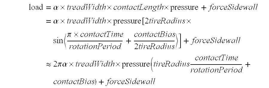
- where treadWidth is the width of the tread, treadWidth×contactLength is the area of applied pressure, forceSidewall is the effective resiliency of the tire sidewall to collapse, contactBias is related to the width of the base plate, and α is a proportionality constant nearly equal to 1. The treadWidth is known from the tire specifications, forceSidewall is known by the tire manufacturer, the tire pressure is measured by a pressure sensor within the tire, and the proportionality constant α and the contactBias are determined as those which best fit laboratory data.
- The means and standard deviations of the timing data can be used to calculate the mean and standard deviation of the load estimate. The standard deviation, σ, is given by

- Determining Tire Molar Air Content: According to the Ideal Gas Law,
- pressure×volume=R×moles×temperature
- where R is the Universal Gas Constant (8.31451 J/mole/° K.), moles is the number of 6.022×10 23 molecules of gas being considered, volume is the volume within which the molecules are constrained, and pressure and temperature are the pressure within the volume and the temperature of the gas.
- In some cases the deflationVolume is insignificant in contrast with the maxVolume and thus

- otherwise the full relationship needs to be used

- and, so long as air is not physically added or removed from the tire, this value is constant regardless of pressure or temperature or load. It is the absolute measure of tire inflation and a regular reduction (negative slope) of the molar content indicates an air leak.
- The relationship between moles, pressure, temperature, and contactLength, since contactLength is itself a function of load, becomes one between moles, pressure, temperature and load:

- Given any three, the fourth can be calculated.
- Determining Vehicle Mass and the Distribution of Mass: The distribution of mass is concisely described by the total mass and the location of the center-of-mass. The center-of-mass is the effective point location of the total mass as acted on by all external forces; the forces acting on a four-wheeled moving vehicle are shown in FIG. 26. The reactive forces of the road surface, in the z direction, are equal to the tire loads but opposite in direction, vehicleMass is the vehicle mass, accForward is the net forward (y direction) acceleration of the vehicle due to engine power or gravity on non-level roads, and is entered in its opposite direction to describe its effect on the load; accRadial is the net radial acceleration due to a turn (x direction) and is entered in its opposite direction to describe its centrifugal effect on the load; and accGravity is the acceleration of gravity (−z direction). Imposing zero net torque about each of the vehicle road contact axes:
- τ0,1=−vehicleMass×accGravity×Y c+vehicleMass×accForward×Z c+(load0,Y+loadX,Y)Y≡0
- τ2,3=vehicleMass×accGravity(Y−Y c)+vehicleMass×accForward×Z c−(load0,0+loadX,0)Y≡0
- τ0,2=vehicleMass×accGravity×X c−vehicleMass×accRadial×Z c−(loadX,0+loadX,Y)X≡0
- τ1,3=−vehicleMass×accGravity(X−X c)−vehicleMass×accRadial×Z c+(load0,0+load0,Y)X≡0
- where accForward and accRadial are measured by vehicle accelerometers; accGravity, X, Y, and Z are known; load 0,0, load0,Y, loadX,0, and loadX,Y are the calculated tire loads; and vehicleMass, Xc, Yc, and Zc are unknowns to be determined. These four equations can be written in matrix form a
- M load−Ax=0
- where

- Initially it would seem the solution is the simple matrix inversion
- x=A −1 M load
- with
- vehicleMass=x(1)
- X c =x(2)/x(1)
- Y c =x(3)/x(1)
- Z c =x(4)/x(1)
- However, the fourth column of A is linearly related to the sum of the second and third columns and the matrix cannot be inverted. The M matrix also cannot be inverted for a similar reason. This means there are less than four independent relationships among the four unknowns.
- Algebraically solving the linear coupled equations: there are only three independent relations:

- These equations suggest an algorithm to determine the mass and center-of-mass as:
- the vehicleMass can always be determined as

- if there is no accForward, then

- if there is no accRadial then

- having determined X c or Yc, Zc is determined once there is either accForward or accRadial:

- As information is received from the tires over many observation periods, a simple means to track the center-of-mass in time would be to average the values (weighted equally) using a sliding window averager or a digital low-pass filter. But a better method would be one that weights values with large standard deviations less than those with small ones, and an even better one would optimally weight the values to minimize the standard deviation of the result. The optimal algorithm is referred to as a stochastic state estimator, a Kalman filter, and has the advantage of automatically implementing the above algorithm without having to invert A or M. Given the means and standard deviations of the load estimates, such an algorithm can take full advantage of all the information and automatically adapt to the vehicle accelerations. The result is the real-time optimal estimation of the four constants [vehicleMass, vehicleMass×X c, vehicleMass×Yc, vehicleMass×Zc] and the standard deviations of these estimates.
- The Kalman filter is linear in state and measurement:

- where x=[vehicleMass vehicleMass×X c vehicleMass×Yc vehicleMass×Zc]T, and the state noise covariance matrix is selected to trade-off the desired estimate accuracies against the filter ability to track changing values. The filter begins with an initialization phase comprising the following steps and equations:
- define vehicle dimensions X, Y
- define initial values of vehicleMass 0 and σvehicleMass,0
- define initial values of x center of mass X c,0 and σXc,0
- define initial values of y center of mass Y c,0 and σYc,0
- define initial values of z center of mass Z c,0 and σZc,0
- define state noise σ δvehicleMass,σδXc,σδZc

- and each load set is processed according to the following steps and equations:
- get measurement mean load,0,0,i+1 and σload,0,0,i+1 at ti+1
- get measurement mean load,0,Y,i+1 and σload,0,Y,i+1 at ti+1
- get measurement mean load,X,0,i+1 and σload,X,0,i+1 at ti+1
- get measurement mean load,X,Y,i+1 and σload,X,Y,i+1 at ti+1
- define the measurement observable:

- predict the state vector at t i+1:

- predict the observable at t i+1:

- calculate the Kalman gain at t i+1: Kalman gain matrix

- correct the state at t i+1:

- While the filter is linear, the actual center-of-mass components are non-linearly related to the filter state estimates and are generated according to the following steps and equations:

- A similar set of relations can be written for trailers, trucks, and so forth.
- Implementation of the Vehicle Data Processor 58: The term “Vehicle Data Processor” is a generic term used herein to describe the various microprocessors, micro-controllers, and other computing devices and their software programs used to satisfy the requirements of this invention. The processors responsible for the vehicle control system operation are considered separate and distributed among its various subsystems. The vehicle data processor 58 (FIG. 2) is responsible for accessing the tire data received by the
vehicle receiver 56, data from the vehicledata storage unit 62 and thevehicle control system 60, and for performing the calculations required of this invention. - The vehicle data processor 58:
- responds to the indication from the vehicle data storage device that new tire data is available and attempts to verify the message;
- reads the tire parameters from data storage: rimRadius, tireRadius, tangentialOffset, α proportionality constant, contactBias, treadWidth, forceSidewall, kBallooning vs. contactLength, deflationVolume vs. contactLength, baseplateWidth, maxPressure, maxDeflation, maxDeflectionAngle, maxTemperature, maxLoad;
- reads vehicle parameters from data storage: X and Y vehicle tire positions;
- calculates the anticipatedPeakAcceleration is using

- from the reported rotationPeriod and compared to the reported peakToPeakAcceleration;
- if the message is valid and the anticipatedPeakToPeakAcceleration compares favorably with the peakToPeakAcceleration:
- the means and standard deviations of the instantaneous contactLength and of the load are calculated from the reported means and standard deviations of contactTime and of rotationPeriod based on

- the accForward and accRadial are acquired from vehicle sensors and the mean and standard deviation of the instantaneous load are processed by the Kalman filter mass and center-of-mass tracking equations based on

- the mean and standard deviation of the volume of the tire are determined from the mean and standard deviation of the contactLength based on

- the mean and standard deviation of the tire molar content are determined from the mean and standard deviation of the tire volume and the reported tire pressure and temperature based on

- the mean and standard deviation of the tire deflation and deflection angle are determined from the mean and standard deviation of the instantaneous contactLength where deflation and deflection angle are based on

- vehicle mass and center-of-mass are sent to the vehicle control system; and
- tire load, pressure, and moles are evaluated with results sent to the operator display.
- The tire pressure required to establish a deflection of deflectionAngleDesired at with a given load is

- The tire pressure required to establish a deflation of deflationDesired at a given load is

- The
vehicle data processor 58 knows a great deal about each tire: - load
- pressure
- temperature
- molar content
- contactLength
- deflation
- deflection angle
- and the manufacturer places limits:
pressure conditions ◯ pressure <maxPressure to limit the internal forces on the tire structure ◯ deflation <maxDeflation to provide a margin so the tire does not bottom out ◯ deflection <maxDeflectionAngle to minimize the bending stresses angle on the tire structure temperature <maxTemperature to limit the heating of the tire structure load <maxLoad to limit the internal force on the tire structure - The pressure conditions reduce to the

- If the temperature condition is not met, the operator must stop and cool the tire. If the load and pressure conditions are not met, the operator must alter the load on the tire. If the pressure condition is met, and the tire pressure is not within the proximity of pressureRecommended, the operator must stop and change the tire pressure. If the tire deflation, deflection angle, or volume changes abruptly, the tire has suffered a blowout.
- 7. The Tire-Identifying
Plaque 54 and the Tire-IdentifyingPlaque Scanner 76 - The values of certain tire specific parameters are required by the
vehicle data processor 58 in order to perform its duties related to this invention including: - rimRadius, tireRadius, tangentialOffset, contactBias, α proportionality constant, treadWidth, forceSidewall, kBallooning vs. contactLength, deflationVolume vs. contactLength, baseplateWidth, maxPressure, maxDeflation, maxDeflectionAngle, maxTemperature, maxLoad;
- and a means is included to facilitate their entry. Each tire carries a tire-identifying plaque 54 (FIG. 2) which contains a series of optical, magnetic or other machine readable data markings, and an identifying plaque scanner 76 (FIGS. 2 and 24) is provided with which to read them. When read, the markings define the values of the various parameters, which are then stored in the vehicle
data storage unit 62 for use by thevehicle data processor 58. - The
plaque 54 is also marked with a code, readable by humans, which can be entered at thetechnician console 72 to cause parameter values that are pre-stored in the vehicledata storage unit 62 to be entered for the tire. The plaque and the scanner used when a new tire is mounted on the vehicle. - 8. The
Vehicle Control System 60 - This is a generic term used to describe the various vehicle data processors and subsystems used to control the actuators that move, control and stop the vehicle. The vehicle control system 60 (FIGS. 2 and 24) comprises the
brake controller 60 a (for example, an anti-lock brake unit), the steeringcontroller 60 b, thesuspension controller 60 c, the engine controller 60 d, thetransmission controller 60 e, and any other controllers and their interactions. - For purposes of the present invention, the
vehicle control system 60 is also one that uses the calculated results of this invention to modify the vehicle operation so as to enhance aspects of the vehicle including performance, vehicle stability and safety, and tire safety. - The vehicle
brake control system 60 a adjusts the braking force on each tire according to the load on the tire. Traction Control, Anti-lock Braking and the Electronic Braking Systems use the mass and mass distribution information to more accurately make the needed adjustments. - The mass, the distribution of mass, and the loads on each tire are used to determine the vehicle stability envelope and to select the maximum perturbation allowed from steering commands. This information is applicable to the
steering control system 60 b (Electrically Assisted Steering Systems) to limit the yaw rate. - The vehicle
suspension control system 60 c adjusts the stiffness of the springs for each tire according to the load on the tire. Active Roll Control systems currently use sensed lateral acceleration to increase the hydraulic pressure to move the stabilizer bars in order to remove the body lean when cornering. This same system could also compensate for unequal load distribution. - Given the vehicle mass, the vehicle engine control 60 d acts to limit the available torque so as not to exceed the ratings of the drive train; it also uses vehicle mass to diagnose power loss based on sensed acceleration and generated torque; and adjusts the engine power output based on the driven load to increase fuel efficiency.
- The
vehicle transmission controller 60 e adjusts the gear switch points according to vehicle mass in order to maximize fuel efficiency and power. - The mass, the distribution of mass, and the loads on each tire are used to determine the vehicle stability. This information is applicable to the Vehicle Stability Control Systems.
- The conditions of the vehicle may indicate that the performance of the vehicle is reduced and the driver should restrict his driving maneuvers. The
vehicle control system 60 itself can take action to limit the maximum vehicle speed to maintain stability and not exceed the tire specifications, or to limit steering yaw rate in order to keep rollovers from occurring. - The operator is alerted to the current vehicle control system condition; the actions it has taken on his behalf to safe the vehicle (reducing the maximum attainable speed, steering rate, engine power); and whether he should take further action (change the distribution of mass, restrict driving maneuvers and speed) as needed on a
display device 64. - 9. The Vehicle
Data Storage Unit 62 - This is a generic term used to describe the various vehicle data storage locations used to retain parameter and data values as required by this invention. The information includes historical logs of: excessive tire loads, pressures, temperatures; measures of vehicle instability; steps the control system has taken to adapt to the loads; alarms displayed to the operator; and messages exchanged with the remote monitor receiver-
transmitter 70 through the vehicleremote receiver transmitter 66. - 10. The
Vehicle Operator Display 64 - This device comprises a visual or audible unit, for displaying alerts and vehicle status indications in order to inform the operator, and is a standard feature in today's vehicles. An illustration of such a display is presented in FIG. 27.
- 11. The Vehicle Remote Receiver-
Transmitter 66 and The Remote Monitor Receiver-Transmitter 70 - The vehicle remote receiver-
transmitter 66 comprises a radio frequency receiver-transmitter and antenna used to communicate externally from the vehicle with a remote monitor receiver-transmitter 70 to exchange data between the two. Such remote monitors 70 include a central diagnostic and prognostic facility that checks on the performance and maintenance requirement of the vehicle; governmental or other stations that check the status of passing vehicles (such as a truck weight station to determine the weight of trucks without having them stop and be weighed); police vehicles, and others. Existing vehicle remote receiver-transmitters 66 of this nature are more and more being proposed and implemented in vehicles and use the cellular telephone network and other existing radio frequency links. - As envisioned here, the data provided to the remote monitor receiver-
transmitter 70 include: the vehicle mass; the loads on the tires; indications of excessive tire loads, pressures, temperatures; measures of vehicle instability; steps the control system has taken to adapt to the loads; and the alarms displayed to the operator. - 12. The
Technician Console 72 - This device is a generic term used to describe a device used by a maintenance technician to gain access to the
vehicle data bus 68 in order to diagnose the vehicle systems and to reprogram their functions. Typically it connects through an electrical port located under the dashboard. - 13. Other Embodiments
- While several illustrative embodiments of the invention have been shown and described, numerous variations and alternate embodiments will occur to those skilled in the art. For example, instead of high-pass filtering to reduce the effect of gravity, a correction based on the estimated angular orientation of the acceleration contact detector relative to the gravity vector can be subtracted; instead of an optical or RF communications link between the contact region detector and the tire receiver-transmitter, electrical conductors may be used; only the accelerometer may be coupled to the inner tread lining, with electrical conductors being provided to route the accelerometer output signal directly to the in-tire receiver-transmitter which would incorporate all of the circuitry and functions otherwise distributed between the contact region detector and the in-tire receiver-transmitter; the accelerometer and any support electronics can be embedded within a tire wall rather than be mounted on an inner surface; the contact region detector and the tire receiver-transmitter may be integrated into a single unit mounted on the inner tread lining; instead of being connected to the technician console, the tire identifying plaque scanner may be coupled directly to the vehicle data bus; the tire identifying plaque scanner and the wand may be combined into a single unit; instead of a magnetic energy source in the wand, sonic or radio frequency energy may be employed; instead of optical encoding, the tire identifying plaque and the associated tire identifying plaque scanner can use magnetic encoding; and instead of a battery, another power source can be used. Such variations and alternate embodiments, as well as others, are contemplated, and can be made without departing from the spirit and scope of the invention as defined in the appended claims.
Claims (123)
1. A device for determining the occurrences of deflections of a vehicle tire due to a load while rotating upon a load-bearing surface, the device comprising:
an accelerometer, adapted to be mounted on the tire, for sensing acceleration variations due to load-induced tire deflections and providing an output representative of said acceleration variations; and
an electrical circuit responsive to said output to provide signals representative of the occurrences of said deflections.
2. The device of claim 1 in which:
the accelerometer is adapted to be mounted on an inner surface of the tire.
3. The device of claim 1 in which:
the accelerometer is adapted to be mounted on an inner tread lining of the tire.
4. The device of claim 1 in which:
the accelerometer is adapted to be embedded within a wall of the tire.
5. The device of claim 1 in which:
the accelerometer is adapted to be positioned to sense acceleration variations along a radius of the tire.
6. The device of claim 1 in which:
the accelerometer is adapted to be positioned to sense acceleration variations perpendicular to a radius of the tire.
7. The device of claim 1 which further comprises:
a base plate attached to the accelerometer.
8. The device of claim 7 which further comprises:
an adhesive patch operatively associated with said base plate for attaching the accelerometer to an inner surface of the tire.
9. The device of claim 1 which further comprises:
a fastener for attaching the accelerometer to the tire.
10. A device, adapted to be mounted on a vehicle tire, for determining the occurrences of deflections of the tire due to a load while rotating upon a load bearing surface, the device comprising:
a substrate;
an accelerometer mounted on the substrate for sensing acceleration variations due to load induced tire deflections and providing an output representative of said acceleration variations; and
an electrical circuit mounted on the substrate, said circuit being responsive to said accelerometer output to provide signals representative of the occurrences of said deflections.
11. The device of claim 10 in which:
the substrate is adapted to be mounted on an inner surface of the tire.
12. The device of claim 10 in which:
the substrate is adapted to be mounted on an inner tread lining of the tire.
13. The device of claim 10 in which:
the substrate is adapted to be embedded in a wall of the tire.
14. The device of claim 10 in which:
the accelerometer is adapted to be positioned to sense acceleration variations along a radius of the tire.
15. The device of claim 10 in which:
the accelerometer is adapted to be positioned to sense acceleration variations perpendicular to a radius of the tire.
16. The device of claim 10 in which the device further comprises:
a base plate attached to the substrate for attaching the device to the inner surface of the tire.
17. The device of claim 16 which further comprises:
an adhesive patch operatively associated with said base plate for attaching the device to said inner surface of the tire.
18. The device of claim 10 in which the device further comprises:
a fastener attached to the substrate for attaching the device to said inner surface of the tire.
19. The device of claim 10 in which:
said electrical circuit includes a data processor; and
in which the device further comprises:
an electrical power supply mounted on the substrate, the power supply being connected to power the electrical circuit.
20. The device of claim 19 in which the device further comprises:
a transmitter mounted on the substrate for transmitting to a remote location information based on said signals.
21. The device of claim 20 in which the device further comprises:
a receiver mounted on the substrate for receiving data from said remote location.
22. In a tire adapted to be mounted on a vehicle wheel, a device for determining the occurrences of deflections of the tire due to a load while rotating upon a load-bearing surface, the device comprising:
an accelerometer mounted on the tire, the accelerometer being disposed to sense acceleration variations due to load-induced tire deflections and adapted to provide an output representative of said acceleration variations.
23. The device of claim 22 in which:
the accelerometer is oriented to sense acceleration variations along a radius of the tire.
24. The device of claim 22 in which:
the accelerometer is oriented to sense acceleration variations perpendicular to a radius of the tire.
25. The device of claim 22 in which:
the accelerometer is mounted on an inner surface of the tire.
26. The device of claim 25 in which:
the inner surface comprises an inner tread lining of the tire.
27. The device of claim 22 in which:
the accelerometer is embedded in a wall of the tire.
28. In a tire adapted to be mounted on a vehicle wheel, a device for determining the occurrences of deflections of the tire due to a load while rotating upon a load-bearing surface, the device comprising:
a substrate attached to the tire at a selected radial and circumferential location;
an accelerometer mounted on the substrate, the accelerometer being disposed to respond to acceleration variations in load-induced tire deflections and being adapted to provide an output representative of said acceleration variations; and
an electrical circuit mounted on the substrate, said circuit being responsive to said accelerometer output to provide signals representative of the occurrences of said deflections.
29. The device of claim 28 in which:
the accelerometer is disposed to sense acceleration variations along a radius of the tire.
30. The device of claim 28 in which:
the accelerometer is disposed to sense acceleration variations perpendicular to a radius of the tire.
31. The device of claim 28 in which:
the accelerometer is mounted on an inner surface of the tire.
32. The device of claim 28 which further comprises:
a base plate, the substrate being secured to the base plate, the substrate being attached to the tire by means of said base plate.
33. The device of claim 32 in which:
the base plate has opposed, parallel inner and outer surfaces, the outer surface engaging an inner surface of the tire, the base plate having a periphery; and
in which the device further comprises:
a patch overlying the inner surface of base plate, the base plate being sandwiched between the patch and the inner surface of the tire, the patch having a portion extending beyond the periphery of the base plate, said portion of said patch being bonded to the inner surface of the tire.
34. The device of claim 33 in which:
the patch includes an aperture through which the substrate projects.
35. The device of claim 32 in which:
the substrate is detachably secured to the base plate.
36. The device of claim 28 in which:
the substrate is attached to the tire by means of a fastener.
37. The device of claim 36 in which:
said fastener includes a post anchored in a wall of the tire.
38. The device of claim 28 in which:
said electrical circuit includes a data processor; and
in which the device further comprises:
an electrical power supply for powering the electrical circuit.
39. The device of claim 28 further comprising:
a transmitter mounted on the substrate for transmitting to a remote location information based on said accelerometer output signals.
40. The device of claim 39 further comprising:
a receiver mounted on the substrate for receiving data from said remote location.
41. A device for determining the occurrences of deflections of a vehicle tire due to a load on the tire while rotating upon a load-bearing surface, the device comprising:
means, adapted to be mounted on the tire relative to an inner surface thereof, for sensing acceleration variations in response to load-induced tire deflections and for providing an output representative of said acceleration variations; and
means responsive to said output for providing signals representative of the occurrences of said tire deflections.
42. In a vehicle wheel comprising a tire mounted on a wheel rim, the tire having known geometric parameters, the tire and rim defining a cavity for retaining air under pressure, an apparatus within said cavity for monitoring the load-induced deformation imposed on the tire during rotation thereof on a load-bearing surface, said apparatus comprising:
a. a device attached to the tire for determining the occurrences of deflections of the tire due to a load on the tire while rotating upon the load bearing surface, the device comprising:
(1) an accelerometer disposed to sense acceleration variations due to load-induced tire deflections and being adapted to provide an output representative of said acceleration variations;
(2) an electrical circuit responsive to said accelerometer output to provide signals representative of the occurrences of said tire deflections; and
(3) a transmitter coupled to said electrical circuit and adapted to transmit signals representative of said tire deflection signals; and
b. a receiver positioned to receive said signals transmitted by said transmitter.
43. The apparatus of claim 42 further comprising:
a processor responsive to said received signals, for determining the tire deformation based on said received signals and the known geometric parameters of the tire.
44. The apparatus of claim 42 in which:
the tire deformation is selected from the group consisting of the length of the load-bearing surface contact; the deflection angle of the tire relative to the load-bearing surface contact; the deflation of the tire; the volume of the tire; and the deflation volume of the tire.
45. The apparatus of claim 42 further comprising:
a communications link for coupling the transmitter and the receiver.
46. The apparatus of claim 45 in which:
the communications link is an optical link.
47. The apparatus of claim 45 in which:
the communications link is an RF link.
48. The apparatus of claim 42 in which:
the vehicle wheel includes a valve stem communicating with the cavity defined by the tire and wheel rim, the valve stem including an inner portion projecting into said cavity; and
the transmitter is mounted on said inner portion of the valve stem.
49. The apparatus of claim 42 further comprising:
an air pressure sensor, a second transmitter and a second electrical circuit coupling the receiver, the pressure sensor and the second transmitter, the second transmitter being adapted to transmit tire deflection signals and signals representative of the air pressure, to a location remote from the vehicle wheel.
50. The apparatus of claim 42 in which:
the accelerometer is disposed to sense acceleration variations along a radius of the tire.
51. The apparatus of claim 42 in which:
the accelerometer is disposed to sense acceleration variations perpendicular to a radius of the tire.
52. The apparatus of claim 42 further comprising:
a base plate, the device being attached to the tire by means of the base plate.
53. The apparatus of claim 52 in which:
the base plate has opposed, parallel inner and outer surfaces, the outer surface engaging an inner surface of the tire, the base plate having a periphery; and
in which the apparatus further comprises:
a patch overlying the inner surface of the base plate, the base plate being sandwiched between the patch and the inner surface of the tire, the patch having a portion extending beyond the periphery of the base plate, said portion of said patch being bonded to the inner surface of the tire.
54. The apparatus of claim 53 in which:
the patch includes an opening through which the device projects.
55. The apparatus of claim 42 further comprising:
a fastener for attaching the device to the tire.
56. The apparatus of claim 55 in which:
the fastener is adapted to releasably attach the device to the tire.
57. In a vehicle wheel comprising a tire mounted on a wheel rim, the tire and rim defining a cavity for retaining air under pressure, an apparatus for monitoring the load imposed on the tire during rotation thereof on a load-bearing surface, said apparatus comprising:
an accelerometer disposed to sense acceleration variations due to load induced tire deflections and for providing an output representative of said acceleration variations;
a first electrical circuit responsive to said accelerometer output to provide signals representative of the occurrences of said tire deflections;
a pressure sensor disposed to sense the pressure of the air within the cavity and provide an output representative of said pressure;
a second electrical circuit responsive to said pressure sensor output to provide signals representative of said air pressure; and
a transmitter coupled to said first and second electrical circuits and adapted to transmit signals representative of said tire deflection and pressure signals;
58. In a vehicle wheel comprising a tire mounted on a wheel rim, the tire and rim defining a cavity for retaining air under pressure, an apparatus for monitoring the molar quantity of air within the tire during rotation thereof on a load-bearing surface, said apparatus comprising:
an accelerometer disposed to sense acceleration variations due to load induced tire deflections and for providing an output representative of said acceleration variations;
a first electrical circuit responsive to said accelerometer output to provide signals representative of the occurrences of said tire deflections;
a pressure sensor disposed to sense the pressure of the air within the cavity and to provide an output representative of said pressure;
a second electrical circuit responsive to said pressure sensor output to provide signals representative of said air pressure;
a temperature sensor disposed to sense the temperature of the air within the cavity and to provide an output representative of said temperature;
a third electrical circuit responsive to said temperature sensor output to provide signals representative of said air temperature; and
a transmitter coupled to said first, second and third electrical circuits and adapted to transmit signals representative of said tire deflection and air pressure and temperature signals.
59. An apparatus for monitoring a load induced deformation imposed on a tire during rotation thereof on a load-bearing surface, the tire having known geometric parameters, said apparatus comprising:
means, attached to a localized region within the tire, for sensing the acceleration of said localized region in response to variations in load-induced tire deflections, and for providing an output representative of said acceleration;
means responsive to said acceleration-representative output for transmitting signals representative of the occurrences of said tire deflections;
means for receiving said transmitted signals; and
means for computing the tire deformation using the received signals and the known geometric parameters of the tire.
60. An apparatus for monitoring the load imposed on a tire during rotation thereof on a load-bearing surface, the tire having known geometric parameters, the tire being mounted on a wheel rim, the tire and rim defining a cavity for retaining air under pressure, said apparatus comprising:
means, attached to a localized region within the tire, for sensing the acceleration of said localized region due to load-induced tire deflections, and for providing an output representative of said acceleration;
means for sensing the air pressure within said cavity and for providing an output representative of said pressure;
means responsive to said acceleration-representative output and said pressure-representative output for transmitting signals representative of said pressure and the occurrences of said tire deflections;
means for receiving said transmitted signals; and
means for computing the tire load based on received signals and the known geometric parameters of the tire.
61. An apparatus for monitoring the molar quantity of air within a tire during rotation thereof on a load-bearing surface, the tire having known geometric parameters, the tire being mounted on a wheel rim, the tire and rim defining a cavity for retaining air under pressure, said apparatus comprising:
means, attached to a localized region within the tire, for sensing the acceleration of said localized region due to load-induced tire deflections, and for providing an output representative of said acceleration;
means for sensing the air pressure within said tire and for providing an output representative of said pressure;
means for sensing the air temperature within said tire and for providing an output representative of said temperature;
means responsive to said acceleration-representative output, said pressure-representative output and said temperature-representative output for transmitting signals representative of said pressure and said temperature and of the occurrences of said tire deflections;
means for receiving said transmitted signals; and
means for computing the tire molar air content based on the received signals and the known geometric parameters of the tire.
62. In a vehicle wheel comprising a tire mounted on a wheel rim, the tire having known geometric parameters, the tire and rim defining a cavity for retaining air under pressure, an apparatus for monitoring the load-induced deformation imposed on the tire during rotation thereof on a load-bearing surface, said apparatus comprising:
an accelerometer attached to a wall of the tire, the accelerometer being disposed to sense acceleration variations due to load-induced tire deflections and being adapted to provide an output representative of said acceleration variations;
an electrical circuit responsive to said accelerometer output to provide signals representative of the occurrences of said tire deflections; and
a transmitter coupled to said electrical circuit, said transmitter being adapted to transmit signals representative of said tire deflection signals.
63. The apparatus of claim 62 in which:
the accelerometer, electrical circuit and transmitter are integrated into a single unit.
64. The apparatus of claim 63 in which:
said single unit is releasably attached to said tire wall.
65. The apparatus of claim 63 in which:
said single unit is embedded in said tire wall.
66. The apparatus of claim 63 further comprising:
a patch for securing the single unit to a wall of the tire.
67. The apparatus of claim 63 further comprising:
a fastener for securing the single unit to a wall of the tire.
68. The apparatus of claim 67 in which:
said fastener releasably secures the unit to the tire wall.
69. The apparatus of claim 62 further comprising:
a receiver positioned to receive said tire deflection signals transmitted by said transmitter.
70. The apparatus of claim 69 further comprising:
a communications link for coupling the transmitter and the receiver.
71. The apparatus of claim 70 in which:
the communications link is an optical link.
72. The apparatus of claim 70 in which:
the communications link is an RF link.
73. The apparatus of claim 62 further comprising:
a second transmitter, the second transmitter being coupled to said receiver and adapted to transmit said tire deflection signals to a location remote from the vehicle wheel.
74. The apparatus of claim 62 in which:
the accelerometer is disposed to sense acceleration variations along a radius of the tire.
75. The apparatus of claim 62 in which:
the accelerometer is disposed to sense acceleration variations perpendicular to a radius of the tire.
76. A method for determining the occurrence of a deflection of a vehicle tire due to a load on the tire while rotating on a load bearing surface, the method comprising the steps of:
sensing acceleration in a local region of the tire;
detecting an acceleration variation caused by the load induced deflection of the tire; and
generating a signal in response to the detected acceleration variation, said signal indicating the occurrence of the deflection.
77. The method of claim 76 further comprising the step of:
correcting said signal for the effect of gravity.
78. The method of claim 77 in which:
said correcting step is performed by correcting for an estimated gravitational term.
79. The method of claim 78 in which said correcting step comprises the steps of:
establishing a rotational index reference;
determining the tire rotational position relative to the index; and
determining the gravitational term based on the tire rotational position.
80. The method of claim 79 in which the correcting step further comprises the step of:
inhibiting the frequency band in which the effect of gravity is expressed.
81. The method of claim 76 further comprising the step of:
correcting said signal for the effect of road noise.
82. The method of claim 81 in which:
the effect of road noise is corrected by inhibiting the frequency band in which said road noise is expressed.
83. A method for determining the occurrence of a deflection of a vehicle tire due to a load on the tire while rotating on a load bearing surface comprising the steps of:
sensing acceleration in a local region of the tire;
generating a first signal representative of the sensed acceleration;
comparing the first signal with a second signal representative of a reference acceleration; and
generating a third signal indicating the occurrence of the deflection in response to the comparison of the first and second signals.
84. The method of claim 83 further comprising the step of:
correcting for the effect of gravity.
85. The method of claim 84 in which:
said correcting step is performed by correcting for an estimated gravitational term.
86. The method of claim 85 in which said correcting step comprises the steps of:
establishing a rotational index reference;
determining the tire rotational position relative to the index; and
determining the gravitational term based on the tire rotational position.
87. The method of claim 86 in which the correcting step further comprises the step of:
inhibiting the frequency band in which the effect of gravity is expressed.
88. The method of claim 83 further comprising the step of:
correcting for the effect of road noise.
89. The method of claim 88 in which:
the effect of road noise is corrected by inhibiting the frequency band in which said road noise is expressed.
90. A method for determining the deformation of a loaded vehicle tire mounted on a rim, the tire having a contact region between the tire and a load-bearing surface, the contact region being delimited by a leading edge and a trailing edge, the tire having known geometric parameters, the tire and rim defining an interior tire cavity, the method comprising the steps of:
sensing acceleration in a local region of the tire;
detecting the occurrences of a first acceleration variation and a second acceleration variation occurring, respectively, at said leading and trailing edges of the contact region;
determining the elapsed time between the occurrences of said first and second acceleration variations;
determining the rotational period of the tire based on the time between the occurrences of sequential acceleration variations at said leading edge or at said trailing edge; and
computing the tire deformation based on the ratio of said elapsed time to said rotational period and the known geometric parameters of the tire.
91. The method of claim 90 in which:
the deformation is selected from the group consisting of the length of the contact region; the tire deflation; the tire deflation volume; the tire volume; and the tire deflection angle.
92. A method for determining the molar air content of a loaded vehicle tire mounted on a rim, the tire having a contact region between the tire and a load-bearing surface, the contact region being delimited by a leading edge and a trailing edge, the tire having known geometric parameters, the tire and rim defining an interior tire cavity, the method comprising the steps of:
measuring the pressure and the temperature of the air within the tire cavity;
generating signals representative of said measured air pressure and temperature;
sensing acceleration in a local region of the tire;
detecting the occurrences of a first acceleration variation and a second acceleration variation occurring, respectively, at said leading and trailing edges of the contact region;
determining the elapsed time between the occurrences of said first and second acceleration variations and generating a signal representative of said elapsed time;
determining the rotational period of the tire based on the time between the occurrences of sequential acceleration variations at said leading edge or at said trailing edge; and
computing the molar air content of the loaded tire based on said signals and the known geometric parameters of the tire.
93. A method for determining the leakage of molar air content from a loaded vehicle tire mounted on a rim, the tire having a contact region between the tire and a load-bearing surface, the contact region being delimited by a leading edge and a trailing edge, the tire having known geometric parameters, the tire and rim defining an interior tire cavity, the method comprising the steps of:
measuring the pressure and the temperature of the air within the tire cavity;
generating signals representative of said measured air pressure and temperature;
sensing acceleration in a local region of the tire;
detecting the occurrences of a first acceleration variation and a second acceleration variation occurring, respectively, at said leading and trailing edges of the contact region;
determining the elapsed time between the occurrences of said first and second acceleration variations and generating a signal representative of said elapsed time;
determining the rotational period of the tire based on the time between the occurrences of sequential acceleration variations at said leading edge or at said trailing edge; and
computing the molar air content of the loaded tire based on the said signals and the known geometric parameters of the tire; and
determining that the rate of change of the molar air content is negative.
94. A method for determining the load on a loaded vehicle tire mounted on a rim, the tire and rim defining an interior tire cavity, the tire having a contact region between the tire and a load-bearing surface, the contact region being delimited by a leading edge and a trailing edge, the tire having known geometric parameters, said method comprising the steps of:
measuring the pressure of the air within the tire cavity;
generating a signal representative of said measured air pressure;
sensing acceleration in a local region of the tire;
detecting the occurrences of a first acceleration variation and a second acceleration variation occurring, respectively, at said leading and trailing edges of the contact region;
determining the elapsed time between the occurrences of said first and second acceleration variations and generating a signal representative of said elapsed time;
determining the rotational period of the tire based on the time between the occurrences of sequential acceleration variations at said leading edge or at said trailing edge; and
computing the load on the loaded tire based on the known geometric parameters of the tire and said signals.
95. A method for determining the total mass of a vehicle supported by a plurality of wheels, each of the wheels comprising a tire mounted on a rim, the tire and rim of each wheel defining an interior tire cavity, each tire having a contact region between the tire and a load-bearing surface, the contact region being delimited by a leading edge and a trailing edge, each tire having known geometric parameters, said method comprising the steps of:
a. for each tire:
(1) measuring the pressure of the air within the tire cavity;
(2) generating a signal representative of said measured air pressure;
(3) sensing acceleration in a local region of the tire;
(4) detecting the occurrences of a first acceleration variation and a second acceleration variation occurring, respectively, at said leading and trailing edges of the contact region;
(5) determining the elapsed time between the occurrences of said first and second acceleration variations and generating a signal representative of said elapsed time; and
(6) determining the rotational period of the tire based on the time between the occurrences of sequential acceleration variations at said leading edge or at said trailing edge; and
b. computing the total mass of the vehicle based on said signals from each of the plurality of tires and their known geometric parameters.
96. A method for determining the distribution of mass of a vehicle supported by a plurality of wheels, each of the wheels comprising a tire mounted on a rim, the tire and rim of each wheel defining an interior tire cavity, each tire having a contact region between the tire and a load-bearing surface, the contact region being delimited by a leading edge and a trailing edge, each tire having known geometric parameters and position on the vehicle, said method comprising the steps of:
a. for each tire:
(1) measuring the pressure of the air within the tire cavity;
(2) generating a signal representative of said measured air pressure;
(3) sensing acceleration in a local region of the tire;
(4) detecting the occurrences of a first acceleration variation and a second acceleration variation occurring, respectively, at said leading and trailing edges of the deflection;
(5) determining the elapsed time between the occurrences of said first and second acceleration variations and generating a signal representative of said elapsed time; and
(6) determining the rotational period of the tire based on the time between the occurrences of sequential acceleration variations at said leading edge or at said trailing edge; and
b. computing the distribution of mass of the vehicle based on said signals and the known geometric parameters and positions of each of the plurality of tires.
97. The method of claim 96 further including the step of:
determining at least one vehicle motion parameter and generating a signal representative of said motion parameter;
and in which:
the computing step is additionally based on the signal representative of said motion parameter.
98. The method of claim 96 in which:
the distribution of mass is the two-dimensional center of mass of the vehicle.
99. The method of claim 96 further including the step of:
determining at least one vehicle motion parameter and generating a signal representative of said motion parameter;
and in which:
the computing step is additionally based on the signal representative of said motion parameter and the distribution of mass is the three-dimensional center of mass of the vehicle.
100. The method of claim 96 further including the steps of:
a. for each tire:
(1) determining a plurality of elapsed times and rotational periods over a series of tire rotations; and
(2) determining the nominal values of the plurality of elapsed times and of rotational periods and their variablility about their nominal values and generating signals representative of said nominal values and variability;
b. computing the nominal value and the variability about the nominal value of the distribution of mass of the vehicle based on said signals and the known geometric parameters and positions of each of the plurality of tires.
101. A system for monitoring in real time the load-induced deflection on at least one tire supporting a vehicle and for providing deflection-related information, the at least one tire being mounted on a rim and defining with said rim an interior tire cavity, the at least one tire having a contact region between the at least one tire and a load-bearing surface, the at least one tire having known parameter values, the at least one tire having an on-contact time and a rotational period, said system comprising:
an accelerometer disposed within the at least one tire to sense acceleration variations due to load induced tire deflections and for providing an output representative of said acceleration variations;
an electrical circuit responsive to said accelerometer output for producing signals from which the ratio of the on-contact time to the rotational period of the at least one tire may be determined;
a transmitter mounted within the tire cavity responsive to said ratio-determining signals, for transmitting a signal representative thereof to a location within said vehicle remote from the at least one tire;
a receiver within the vehicle remote from the at least one tire for receiving said signals transmitted by the transmitter mounted within the tire cavity;
a memory for storing known values comprising parameter values of the at least one tire; and
a computer connected to said receiver and memory for computing said deflection-related information based on said transmitted signal and said known tire parameter values.
102. The system of claim 101 which further includes:
a remote receiver-transmitter carried by the vehicle and coupled to the computer for receiving said deflection-related information and for transmitting said information to a monitor remote from said vehicle; and
a receiver remote from the vehicle for receiving said load-related information from the vehicle.
103. The system of claim 101 in which the at least one tire includes an exterior surface and which further includes:
machine-readable indicia on the exterior surface of the at least one tire, said indicia identifying at least one parameter value affecting the determination of tire deflection-related information.
104. The system of claim 103 which includes:
a scanner for reading said machine-readable parameter indicia, and connected to store the at least one identified parameter value into said memory.
105. The system of claim 101 which further comprises:
a display at an operator's station within the vehicle, said display being connected to said computer for displaying said deflection-related information.
106. The system of claim 101 in which:
the computer is coupled to at least one adaptive vehicle control system responsive to said deflection-related information, said at least one adaptive vehicle control system being associated with at least one of the following: an engine, a transmission, a steering system, a brake system, and a suspension system.
107. The system of claim 101 in which:
the memory is adapted to store vehicle related parameters; and in which:
said computer is adapted to compute said deflection-related information based also on said vehicle related parameters.
108. The system of claim 101 in which:
the deflection-related information is selected from the group consisting of the length of the load-bearing surface contact; the deflection angle of the tire relative to the load-bearing surface contact; the deflation of the tire; the volume of the tire; and the deflation volume of the tire.
109. The system of claim 101 which further includes:
a pressure sensor mounted within the tire cavity for sensing the pressure of the air within the cavity and generating a signal representative of said pressure; and
said computer is adapted to compute said deflection-related information based also on said pressure signal.
110. The system of claim 109 where the deflection-related information is the tire load.
111. The system of claim 109 in which:
the system monitors the deflection on each of a plurality of loaded tires supporting the vehicle; and
the deflection-related information is selected from the group consisting of total vehicle mass, vehicle mass distribution and the location of the center of mass of the vehicle.
112. The system of claim 109 further including:
a. within each tire:
(1) a temperature sensor mounted within the tire cavity for sensing the temperature of the air within the cavity and generating a signal representative of said temperature; and
(2) the transmitter within the tire and the receiver within the vehicle being also responsive to said temperature signal for transmitting and receiving signals representative thereof;
b. the memory is furthermore adapted to store known parameter values affecting the determination of tire molar content; and
c. the computer is furthermore adapted to compute tire molar content related information.
113. The system of claim 101 in which:
a. the electrical circuit responsive to said accelerometer output is further adapted to:
(1) determine multiple samples of values from which said ratio can be determined; and
(2) reduce the samples to signals that represent, of the samples, the nominal values and the variation about the nominal; and in which
b. the transmitter within the tire and the receiver within the vehicle being also responsive to said nominal and variation signals; and
c. said computer is further adapted to compute said deflection-related information based on said nominal and variation signals.
114. A vehicle tire including a sidewall having an exterior surface, the tire comprising:
machine-readable information disposed on the exterior surface of the tire sidewall within a local region of said surface, the information identifying at least one parameter value relating to the determination of the load-induced deformation capability of the tire.
115. The tire of claim 114 in which:
the parameter value is identified by providing its numeric value.
116. The tire of claim 114 in which:
the information is readable magnetically.
117. The tire of claim 114 in which:
the information is readable optically.
118. The tire of claim 114 which further comprises:
a plaque mounted on the exterior surface of the tire within said local region thereof, the plaque having an outer surface carrying said machine-readable information.
119. An electronic package adapted to be attached to an inner surface of a vehicle tire, the package comprising:
a base plate attached to said package; and
an adhesive patch, operatively associated with said base plate, for attaching the package to said inner surface of the tire.
120. The package of claim 119 in which:
the base plate comprises parallel inner and outer surfaces and a periphery, the outer surface of the base plate being adapted to engage the inner surface of the tire, the patch overlying the inner surface of the base plate, the base plate being thereby adapted to be sandwiched between the patch and said inner surface of the tire; and
the patch having a portion extending beyond the periphery of the base plate, said portion of the patch being adapted to be bonded to said inner surface of the tire.
121. The device of claim 120 for which:
the patch includes an opening through which the package projects.
122. A vehicle tire having a wall, an inner surface and an interior cavity, the tire comprising:
an electronic package;
a post anchored in the wall of the tire and having an end projecting from said inner surface into the interior cavity of the tire; and
a fastener coupling the electronic package to the projecting end of the post.
123. The vehicle tire of claim 122 in which:
the fastener releasably couples the electronic package to the post, the package being thereby removable from said post and transferable to another vehicle tire equipped with a post.
Priority Applications (4)
| Application Number | Priority Date | Filing Date | Title |
|---|---|---|---|
| US10/143,312 US20030058118A1 (en) | 2001-05-15 | 2002-05-10 | Vehicle and vehicle tire monitoring system, apparatus and method |
| EP02729190A EP1390218A2 (en) | 2001-05-15 | 2002-05-13 | Vehicle and vehicle tire monitoring system, apparatus and method |
| PCT/US2002/015060 WO2002092364A2 (en) | 2001-05-15 | 2002-05-13 | Vehicle and vehicle tire monitoring system, apparatus and method |
| AU2002259198A AU2002259198A1 (en) | 2001-05-15 | 2002-05-13 | Vehicle and vehicle tire monitoring system, apparatus and method |
Applications Claiming Priority (4)
| Application Number | Priority Date | Filing Date | Title |
|---|---|---|---|
| US29067201P | 2001-05-15 | 2001-05-15 | |
| US30795601P | 2001-07-25 | 2001-07-25 | |
| US32420401P | 2001-09-21 | 2001-09-21 | |
| US10/143,312 US20030058118A1 (en) | 2001-05-15 | 2002-05-10 | Vehicle and vehicle tire monitoring system, apparatus and method |
Publications (1)
| Publication Number | Publication Date |
|---|---|
| US20030058118A1 true US20030058118A1 (en) | 2003-03-27 |
Family
ID=27495561
Family Applications (1)
| Application Number | Title | Priority Date | Filing Date |
|---|---|---|---|
| US10/143,312 Abandoned US20030058118A1 (en) | 2001-05-15 | 2002-05-10 | Vehicle and vehicle tire monitoring system, apparatus and method |
Country Status (4)
| Country | Link |
|---|---|
| US (1) | US20030058118A1 (en) |
| EP (1) | EP1390218A2 (en) |
| AU (1) | AU2002259198A1 (en) |
| WO (1) | WO2002092364A2 (en) |
Cited By (116)
| Publication number | Priority date | Publication date | Assignee | Title |
|---|---|---|---|---|
| US20040064219A1 (en) * | 2000-03-16 | 2004-04-01 | Federico Mancosu | System, tyre and method for determining the behaviour of a tyre in motion |
| US20040078662A1 (en) * | 2002-03-07 | 2004-04-22 | Hamel Michael John | Energy harvesting for wireless sensor operation and data transmission |
| US6819980B2 (en) * | 2001-06-23 | 2004-11-16 | Daimlerchrysler Ag | Method for the avoidance of rollover phenomena in semitrailers |
| WO2005005950A1 (en) * | 2003-07-04 | 2005-01-20 | Pirelli Pneumatici S.P.A. | Method and system for determining a tyre load during the running of a motor vehicle |
| US20050075825A1 (en) * | 2003-10-03 | 2005-04-07 | Yuhong Zheng | Real-time signal processing for vehicle tire load monitoring |
| US6877371B1 (en) * | 2003-11-07 | 2005-04-12 | General Motors Corporation | Method and apparatus for detecting tire pressure |
| US20050080546A1 (en) * | 2002-05-01 | 2005-04-14 | Milot Danny R. | Vehicle stability control enhancement using tire force characteristics |
| US20050097949A1 (en) * | 2003-11-11 | 2005-05-12 | Siemens Aktiengesellschaft | System for monitoring a vehicle with pneumatic tires, signal analysis method, and vehicle tire |
| WO2005053972A1 (en) * | 2003-12-02 | 2005-06-16 | Daimlerchrysler Ag | Method and system for identifying and/or monitoring wheels of a motor vehicle |
| WO2005056311A2 (en) * | 2003-12-11 | 2005-06-23 | Conti Temic Microelectronic Gmbh | Sensor transponder and method for measuring tire contact lengths and wheel load |
| US20050187667A1 (en) * | 2004-02-19 | 2005-08-25 | Johnson Controls Technology Company | System and method for identifying tire position on a vehicle |
| WO2005095133A1 (en) * | 2004-03-23 | 2005-10-13 | Kelsey-Hayes Company | Method and apparatus for vehicle rollover mitigation |
| US6960994B2 (en) * | 2002-02-18 | 2005-11-01 | Toyota Jidosha Kabushiki Kaisha | Vehicle tire information obtaining apparatus and tire information processing apparatus |
| US20060010992A1 (en) * | 2002-06-21 | 2006-01-19 | Hiroshi Shima | Method for measuring forces acted upon tire and apparatus for measuring forces acted upon tire |
| US20060122758A1 (en) * | 2004-12-08 | 2006-06-08 | Bauer Geoffrey B | Reduced order parameter identification for vehicle rollover control system |
| US20060136782A1 (en) * | 2003-04-16 | 2006-06-22 | Michelin Recherche Et Technique S.A. | Method and device for treating a set of components for the wheel of a vehicle |
| EP1674300A2 (en) * | 2004-12-22 | 2006-06-28 | The Goodyear Tire & Rubber Company | Integrated sensor system and method for a tire |
| US20060161327A1 (en) * | 2005-01-18 | 2006-07-20 | Harald Emmerich | Wheel sensor for detecting a vehicle motion |
| US20060169414A1 (en) * | 2005-02-02 | 2006-08-03 | Scott Hillman | Vehicle tire changer with integrated detector for tire pressure sensors |
| US20060190150A1 (en) * | 2005-02-22 | 2006-08-24 | Milot Danny R | Vehicle stability control utilizing static tire data |
| US20060220812A1 (en) * | 2003-06-02 | 2006-10-05 | Siemens Vdo Automotive | Wheel unit for motor vehicle tyre pressure monitoring device |
| WO2007031677A2 (en) * | 2005-09-16 | 2007-03-22 | Peugeot Citroen Automobiles Sa | Method and device for determining the condition of at least one tyre of a vehicle wheel |
| WO2007031678A2 (en) * | 2005-09-16 | 2007-03-22 | Peugeot Citroen Automobiles Sa | Method and system for diagnosing the condition of a motor vehicle tyres |
| US20070069877A1 (en) * | 2005-09-29 | 2007-03-29 | Fogelstrom Kenneth A | Tire pressure monitoring system with permanent tire identification |
| JP2007113957A (en) * | 2005-10-18 | 2007-05-10 | Hitachi Ltd | Friction force sensor and tire with friction force sensor |
| US20070112495A1 (en) * | 2003-07-12 | 2007-05-17 | Torotrak (Development) Limited | Method and device for determining motor vehicle acceleration |
| WO2007063926A1 (en) * | 2005-11-29 | 2007-06-07 | Toyota Jidosha Kabushiki Kaisha | Wheel-state estimation device and vehicle control device |
| US20070156320A1 (en) * | 2000-09-08 | 2007-07-05 | Automotive Technologies International, Inc. | Vehicular Tire Monitoring Based on Sensed Acceleration |
| EP1813493A1 (en) * | 2004-11-19 | 2007-08-01 | The Yokohama Rubber Co., Ltd. | Tire slipping state detecting method and tire slipping state detecting device |
| US20070240501A1 (en) * | 2003-10-24 | 2007-10-18 | Federico Mancosu | Method and System for Determining a Tyre Load During the Running of a Vehicle |
| US20070255510A1 (en) * | 2003-10-31 | 2007-11-01 | Federico Mancosu | Method and a System for Determining the Roughness of a Tyre Rolling Surface |
| US20070299573A1 (en) * | 2006-06-26 | 2007-12-27 | International Truck Intellectual Property Company, Llc | Accelerometer based system for detection of tire tread separation and loose wheels |
| US20080077293A1 (en) * | 2006-05-09 | 2008-03-27 | Lockheed Martin Corporation | System and method for extending the range of run-flat tires |
| US20080129478A1 (en) * | 2006-11-30 | 2008-06-05 | Siemens Vdo Automotive Aktiengesellschaft | Method for Localizing Wheel Electronics Systems |
| US20080255795A1 (en) * | 2007-04-13 | 2008-10-16 | Keynetik, Inc. | Force Sensing Apparatus and Method to Determine the Radius of Rotation of a Moving Object |
| US20080258581A1 (en) * | 2003-12-19 | 2008-10-23 | Enocean Gmbh | Energy converter arranged on rotating elements and used to convert mechanical energy into electric energy |
| US20080272900A1 (en) * | 2004-04-01 | 2008-11-06 | Conti Temic Microelectronic Gmbh | Procedure and Facility for Transmission Between a Control Device and a Wheel Module |
| US20090125251A1 (en) * | 2004-05-12 | 2009-05-14 | Pirelli Pneumatici, S.P.A. | Method for determining a force at the hub of a wheel of a vehicle while traveling and wheel suitable for allowing said method to be carried out |
| US20090134632A1 (en) * | 2007-11-27 | 2009-05-28 | Infineon Technologies Sensonor As | Energy Harvesting System and Method |
| US20090158595A1 (en) * | 2005-10-14 | 2009-06-25 | David Acher | Microemulsion and Shaving Apparatus Comprising a Microemulsion |
| US7552628B2 (en) | 2003-10-24 | 2009-06-30 | Pirelli Pneumatici S.P.A. | Method and system for determining a cornering angle of a tyre during the running of a vehicle |
| US20090271061A1 (en) * | 2008-04-25 | 2009-10-29 | Wang Dexin | System and method for tire cornering power estimation and monitoring |
| US20090293602A1 (en) * | 2008-06-03 | 2009-12-03 | Infineon Technologies Ag | Wireless communication apparatuses, systems and methods |
| US7677095B1 (en) | 2006-12-11 | 2010-03-16 | Kelsey-Hayes Company | Method for providing enhanced stability of a vehicle with a deflated tire |
| US20100114468A1 (en) * | 2008-11-06 | 2010-05-06 | Segway Inc. | Apparatus and method for control of a vehicle |
| US20100126263A1 (en) * | 2007-07-18 | 2010-05-27 | Pirelli Tyre S.P.A. | Method and system for determining operating parameters of a tyre during running of a vehicle |
| US20110098882A1 (en) * | 2004-10-07 | 2011-04-28 | Sumitomo Rubber Industries, Ltd. | Vehicle speed estimation device, method and device for detecting decreased tire pressure using the same |
| WO2011062983A1 (en) * | 2009-11-18 | 2011-05-26 | Geer Derek H | Method, apparatus and system for sensing a signal with automatic adjustments for changing signal levels |
| DE102009057578A1 (en) * | 2009-12-09 | 2011-06-16 | Continental Automotive Gmbh | Device for examining wheel load distribution of multiple tires of vehicle, has receiving unit for receiving sensor signals of multiple tires of vehicle |
| CN102145639A (en) * | 2010-02-05 | 2011-08-10 | 博格华纳贝鲁系统股份有限公司 | Method for monitoring the load of vehicle tires |
| US8024087B2 (en) | 2004-09-29 | 2011-09-20 | Pirelli Tyre S.P.A. | Method and system for determining a cornering angle of a tyre during the running of a vehicle |
| US20110302708A1 (en) * | 2001-11-20 | 2011-12-15 | Parsons Natan E | Passive sensors and control algorithms for faucets and bathroom flushers |
| US8151127B2 (en) | 2000-07-26 | 2012-04-03 | Bridgestone Americas Tire Operations, Llc | System for conserving battery life in a battery operated device |
| DE102010041768A1 (en) * | 2010-09-30 | 2012-04-05 | Bayerische Motoren Werke Aktiengesellschaft | Method for approximate determination of diameter of wheel of motor vehicle, involves determining radial distance of acceleration sensor to wheel midpoint based on determined acceleration of wheel and rotation speed of wheel |
| US20120203400A1 (en) * | 2009-10-14 | 2012-08-09 | Sensordynamics Gmbh | Method for the Measurement and Analysis of Tyre Air Pressure with Allocation of Wheel Positions and System for Tyre Air Pressure Measurement |
| US8266465B2 (en) | 2000-07-26 | 2012-09-11 | Bridgestone Americas Tire Operation, LLC | System for conserving battery life in a battery operated device |
| US20120268263A1 (en) * | 2009-12-03 | 2012-10-25 | Seetron Inc. | Tire position detecting system and tire position detecting method |
| US20130006440A1 (en) * | 2011-06-30 | 2013-01-03 | GM Global Technology Operations LLC | Vehicle using tire temperature to adjust active chassis systems |
| US8565967B2 (en) | 2011-12-21 | 2013-10-22 | Infineon Technologies Ag | Acceleration detection and angular position determination systems and methods in tire pressure monitoring systems |
| US20130304416A1 (en) * | 2010-12-30 | 2013-11-14 | Continental Automotive Gmbh | Method for determining a pivoting angle of a wheel unit mounted onto a snap-in inflation valve |
| US8593273B2 (en) | 2011-02-07 | 2013-11-26 | Infineon Technologies Ag | Systems and methods for localization of tire pressure monitoring system wheel modules |
| US20140005956A1 (en) * | 2012-06-27 | 2014-01-02 | Amrita Patel | Load estimation system and method for a vehicle tire |
| CN103522997A (en) * | 2012-07-06 | 2014-01-22 | 法国大陆汽车公司 | Method for determining the angular position of an electronic module fixed to the inner face of the tread of a tire |
| US20140058580A1 (en) * | 2012-08-27 | 2014-02-27 | Infineon Technologies Ag | Wheel localizer, wheel localization device, system, method and computer program for locating a position of a wheel |
| US20140107946A1 (en) * | 2012-10-11 | 2014-04-17 | Infineon Technologies Ag | System and Method for Determining the Mileage and Wear of a Tire |
| CN104029684A (en) * | 2013-03-08 | 2014-09-10 | 固特异轮胎和橡胶公司 | Tire Load Estimation System Using Road Longitudinal Profile Adaptive Filtering |
| US20140251015A1 (en) * | 2012-02-28 | 2014-09-11 | Sperry Rail, Inc. | System and Method for Non-Destructive Testing of Railroad Rails Using Ultrasonic Apparatuses Mounted Within Fluid-Filled Tires Maintained at Constant Temperatures |
| US8843267B2 (en) | 2013-01-10 | 2014-09-23 | Infineon Technologies Ag | Wheel localizer, wheel localization device, system, method and computer program for locating a position of a wheel |
| US8849500B2 (en) * | 2012-09-03 | 2014-09-30 | Bridgestone Corporation | System for predicting tire casing life |
| US20150061852A1 (en) * | 2012-11-20 | 2015-03-05 | Liming FU | Tire pressure monitoring systems and methods |
| US20150102921A1 (en) * | 2013-10-10 | 2015-04-16 | Hyundai Mobis Co., Ltd. | Micro leakage detecting device of suspension device and method for detecting micro leakage |
| US20150142259A1 (en) * | 2012-06-11 | 2015-05-21 | Denso Corporation | Wheel position detecting device and tire air pressure detecting apparatus including the same |
| US9038465B2 (en) | 2011-08-29 | 2015-05-26 | Mando Corporation | Method of setting valid output sections of 2-axis acceleration sensor or 3-axis acceleration sensor |
| US9099410B2 (en) | 2003-10-13 | 2015-08-04 | Joseph H. McCain | Microelectronic device with integrated energy source |
| US20150260143A1 (en) * | 2014-03-11 | 2015-09-17 | Voyomotive, Llc | Method of signaling an engine stop or start request |
| DE102009033060B4 (en) * | 2008-08-01 | 2015-09-17 | Infineon Technologies Ag | Tire footprint determining devices, systems and methods |
| US9221309B2 (en) | 2012-02-06 | 2015-12-29 | Infineon Technologies Ag | Wheel localizer, wheel localization device, system, method and computer program for locating a position of a wheel |
| EP3006234A1 (en) * | 2014-10-07 | 2016-04-13 | Sung Jung Minute Industry Co., Ltd. | Method for judging abnormal loading of vehicles |
| US20160129737A1 (en) * | 2014-11-11 | 2016-05-12 | The Goodyear Tire & Rubber Company | Tire wear compensated load estimation system and method |
| US9340211B1 (en) | 2014-12-03 | 2016-05-17 | The Goodyear Tire & Rubber Company | Intelligent tire-based road friction estimation system and method |
| WO2016100434A1 (en) * | 2014-12-16 | 2016-06-23 | Trw Automotive Us Llc | Tire fill assist method and apparatus |
| US20170010184A1 (en) * | 2015-07-08 | 2017-01-12 | The Goodyear Tire & Rubber Company | Tire sensor-based vehicle state estimation system and method |
| US9555675B2 (en) | 2012-11-19 | 2017-01-31 | Compagnie Generale Des Etablissements Michelin | Flexible sensor support for tire inspection |
| US9742566B2 (en) | 2012-02-17 | 2017-08-22 | International Business Machines Corporation | Homomorphic evaluation including key switching, modulus switching, and dynamic noise management |
| DE102004031810B4 (en) * | 2004-07-01 | 2017-11-09 | Continental Aktiengesellschaft | System for generating electrical energy for electronic components |
| US9840118B2 (en) | 2015-12-09 | 2017-12-12 | The Goodyear Tire & Rubber Company | Tire sensor-based robust road surface roughness classification system and method |
| US20170355234A1 (en) * | 2014-12-22 | 2017-12-14 | Continental Automotive Gmbh | Method and system for determining a wheel load acting on a tire of a vehicle |
| US10000100B2 (en) | 2010-12-30 | 2018-06-19 | Compagnie Generale Des Etablissements Michelin | Piezoelectric based system and method for determining tire load |
| US20180222488A1 (en) * | 2017-02-08 | 2018-08-09 | Caterpillar Inc. | Tire management system and method |
| US10093137B2 (en) | 2012-08-27 | 2018-10-09 | Infineon Technologies Ag | Wheel localizer, wheel localization device, system, method and computer program for locating a position of a wheel |
| FR3072165A1 (en) * | 2017-10-10 | 2019-04-12 | Continental Automotive France | METHOD FOR DETERMINING THE THICKNESS OF A TIRE OF A MOTOR VEHICLE |
| US10281298B2 (en) | 2016-07-22 | 2019-05-07 | Infineon Technologies Ag | Wheel localization from reference magnetic field and angular rotation information in TPMS application |
| US10333696B2 (en) | 2015-01-12 | 2019-06-25 | X-Prime, Inc. | Systems and methods for implementing an efficient, scalable homomorphic transformation of encrypted data with minimal data expansion and improved processing efficiency |
| DE112005000543B4 (en) * | 2004-03-09 | 2019-09-26 | Conti Temic Microelectronic Gmbh | wheel module |
| US10502567B2 (en) * | 2014-04-25 | 2019-12-10 | Yamaha Hatsudoki Kabushiki Kaisha | Roll angle estimation device and transport apparatus |
| US10514322B2 (en) * | 2017-12-19 | 2019-12-24 | Ford Global Technologies, Llc | Methods and apparatus for assessing tire health |
| CN110682743A (en) * | 2019-09-30 | 2020-01-14 | 深圳市全昇科技有限公司 | Method for improving signal receiving effect of sensor |
| US20200047566A1 (en) * | 2018-08-13 | 2020-02-13 | Hankook Tire & Technology Co., Ltd. | Tire sensor fixed in screwing manner and tire having the same |
| US20200086695A1 (en) * | 2016-12-23 | 2020-03-19 | Continental Automotive France | Method for identifying the wheels of a motor vehicle |
| WO2020081977A1 (en) * | 2018-10-19 | 2020-04-23 | ClearMotion, Inc. | Method and apparatus for operating suspension systems |
| US10665581B1 (en) | 2019-01-23 | 2020-05-26 | Sandisk Technologies Llc | Three-dimensional semiconductor chip containing memory die bonded to both sides of a support die and methods of making the same |
| DE102018131303A1 (en) * | 2018-12-07 | 2020-06-10 | B-Horizon GmbH | Process for measuring and / or processing measured pressure and / or moisture values |
| US10787047B2 (en) * | 2016-12-22 | 2020-09-29 | Continental Automotive France | Method for pairing a measurement module mounted in a motor vehicle wheel |
| US10879260B2 (en) | 2019-02-28 | 2020-12-29 | Sandisk Technologies Llc | Bonded assembly of a support die and plural memory dies containing laterally shifted vertical interconnections and methods for making the same |
| US10875539B2 (en) * | 2018-08-22 | 2020-12-29 | Infineon Technologies Ag | Tire load estimation |
| CN112498019A (en) * | 2020-11-24 | 2021-03-16 | 广西路桥工程集团有限公司 | Detection system and detection method for detecting vehicle load capacity by utilizing tire pressure |
| US20210080242A1 (en) * | 2015-12-04 | 2021-03-18 | Pavement Analytics Limited | Method and system for measuring deformation of a surface |
| CN112834433A (en) * | 2019-11-22 | 2021-05-25 | 深圳市光鉴科技有限公司 | 4D camera device and electronic equipment |
| DE102019131807A1 (en) * | 2019-11-25 | 2021-05-27 | B-Horizon GmbH | Method for measuring and / or processing measured pressure and / or humidity values based on ambient humidity |
| CN113226801A (en) * | 2018-12-21 | 2021-08-06 | 米其林集团总公司 | Method for obtaining the deformation of a tyre under load while driving |
| JP2021521042A (en) * | 2018-03-29 | 2021-08-26 | ディーア・アンド・カンパニーDeere And Company | A method for dynamically determining tire longitudinal force |
| US20220074785A1 (en) * | 2018-12-21 | 2022-03-10 | Sensata Technologies, Inc. | Method for monitoring a load carrier vehicle, monitoring device for a load carrier vehicle, load carrier vehicle, load carrier vehicle system and swap body |
| US11298991B2 (en) | 2018-11-28 | 2022-04-12 | The Goodyear Tire & Rubber Company | Tire load estimation system and method |
| KR20220045899A (en) * | 2020-10-06 | 2022-04-13 | 더 굿이어 타이어 앤드 러버 캄파니 | System for detection of non-pneumatic tire loading |
| US11338630B2 (en) * | 2015-12-04 | 2022-05-24 | Pavement Analytics Limited | Method and system for measuring deformation of a surface |
| CN114901494A (en) * | 2019-12-30 | 2022-08-12 | 米其林集团总公司 | Method for obtaining a load applied to a pneumatic tyre while rolling |
Families Citing this family (15)
| Publication number | Priority date | Publication date | Assignee | Title |
|---|---|---|---|---|
| JP3895347B2 (en) * | 2004-11-19 | 2007-03-22 | 横浜ゴム株式会社 | Tire deformation amount calculation method and tire deformation amount calculation device |
| FI122392B (en) | 2005-07-14 | 2011-12-30 | Secure Oy W | Vehicle wheel monitoring system and wireless measurement module |
| DE102006028412A1 (en) * | 2006-06-21 | 2007-12-27 | Robert Bosch Gmbh | Method for measuring the air pressure in a vehicle tire |
| DE102007039242A1 (en) * | 2007-08-20 | 2009-02-26 | Robert Bosch Gmbh | Method for operating a sensor on or in a vehicle tire and sensor arrangement |
| DE102008002722A1 (en) | 2008-06-27 | 2009-12-31 | Robert Bosch Gmbh | Tread depth variation determining method for car tire, involves selecting subset of ratios representing measurement for tire contact patch, and inferring subset on variation of tread depth from timely variation of ratios |
| DE102008041608B4 (en) | 2008-08-27 | 2021-08-12 | Robert Bosch Gmbh | Process for the detection of acceleration peaks in tires |
| DE102009057580B4 (en) | 2009-12-09 | 2023-06-15 | Continental Automotive Technologies GmbH | Contact patch evaluation circuit for an electromechanical converter of a tire |
| WO2012110877A1 (en) * | 2011-02-16 | 2012-08-23 | 1814393 Ontario Inc. | Tire pressure sensing mounting system |
| EP3281810B1 (en) * | 2016-08-10 | 2020-12-16 | 4JET Technologies GmbH | Tire processing method, computer program product and batch of tires |
| AU2019279457A1 (en) * | 2018-05-30 | 2021-01-07 | Pavement Analytics Limited | A method and system for measuring deformation of a surface |
| EP3741587B1 (en) * | 2019-05-23 | 2023-09-27 | Melexis Technologies SA | Auto-location using tire mounted system |
| US11203235B2 (en) * | 2020-05-05 | 2021-12-21 | Enervibe Ltd | System for tires pressure and wear detection |
| CN112013937B (en) * | 2020-07-31 | 2022-10-11 | 浙江万安科技股份有限公司 | ABS-based system and method for identifying wheel load in real time |
| CN112287465B (en) * | 2020-11-23 | 2022-03-18 | 吉林大学 | Method for realizing real-time simulation of in-plane tire flexible ring model |
| GB2620962A (en) * | 2022-07-28 | 2024-01-31 | Continental Automotive Gmbh | Vehicle load regulating system and method thereof |
Citations (31)
| Publication number | Priority date | Publication date | Assignee | Title |
|---|---|---|---|---|
| US4364267A (en) * | 1980-08-20 | 1982-12-21 | The Goodyear Tire & Rubber Company | Method and apparatus for correlating tire inflation pressure and load |
| US5247831A (en) * | 1988-11-18 | 1993-09-28 | Fioravanti S.R.L. | Method and system for monitoring the tire footprints of a motor vehicle, particularly for automatically optimizing the behavior of the motor vehicle |
| US5541573A (en) * | 1993-10-09 | 1996-07-30 | Sumitomo Rubber Industries Limited | Method of detecting a deflated tire on a vehicle |
| US5546070A (en) * | 1993-09-02 | 1996-08-13 | Bayerische Motoren Werke Ag | Device for monitoring the air pressure of a tire in motor vehicles with a sensor |
| US5708411A (en) * | 1995-09-25 | 1998-01-13 | D H Products, Llc | Tire monitoring system, device and method |
| US5801306A (en) * | 1996-03-20 | 1998-09-01 | Compagnie Generale Des Etablissements Michelin - Michelin & Cie | Method of processing pressure measurements in a tire monitoring system |
| US5877679A (en) * | 1996-09-13 | 1999-03-02 | Sumitomo Rubber Industries, Ltd. | Sensor for a pneumatic tire |
| US5880363A (en) * | 1996-08-09 | 1999-03-09 | Temic Telefunken Microelectronic Gmbh | Process for checking air pressure in vehicle wheel tires |
| US5889464A (en) * | 1998-03-13 | 1999-03-30 | Huang; Tien-Tsai | Tire pressure indicator including pressure gauges that have a self-generating power capability |
| US5900808A (en) * | 1997-02-21 | 1999-05-04 | Lebo; Michael E. | Low pressure warning system |
| US5924055A (en) * | 1994-11-14 | 1999-07-13 | The Yokohama Rubber Co., Ltd. | Vehicle tire air pressure monitor |
| US5963128A (en) * | 1994-11-22 | 1999-10-05 | Schrader-Bridgeport International, Inc. | Remote tire pressure monitoring system |
| US5960844A (en) * | 1997-12-22 | 1999-10-05 | Bridgestone/Firestone, Inc. | Method and apparatus for monitoring conditions of a vehicle tire |
| US6034597A (en) * | 1996-08-07 | 2000-03-07 | Ami Doduco Gmbh | Process for evaluating the signals from a tire pressure monitoring system |
| US6043738A (en) * | 1998-06-26 | 2000-03-28 | Schrader-Bridgeport International, Inc. | Method and apparatus for identifying remote sending units in a vehicle |
| US6046672A (en) * | 1996-07-29 | 2000-04-04 | Pearman; Kevin Patrick Austin | Tire deflation detector |
| US6087930A (en) * | 1994-02-22 | 2000-07-11 | Computer Methods Corporation | Active integrated circuit transponder and sensor apparatus for transmitting vehicle tire parameter data |
| US6105423A (en) * | 1997-12-17 | 2000-08-22 | Sumitomo Rubber Industries Limited | Sensor for a pneumatic tire |
| US6112587A (en) * | 1997-08-08 | 2000-09-05 | Continental Aktiengesellschaft | Method for assigning the wheel position to tire pressure control devices in a tire pressure control system of a motor vehicle |
| US6115301A (en) * | 1998-03-03 | 2000-09-05 | Kabushiki Kaisha Toshiba | Semiconductor memory device having defect relieving system using data line shift method |
| US6144295A (en) * | 1998-12-11 | 2000-11-07 | Case Corporation | Automatic central tire inflation system |
| US6148888A (en) * | 1995-09-01 | 2000-11-21 | Fast Air, S.L. | Method and system for measuring and adjusting pressure of tires |
| US6175302B1 (en) * | 1999-04-02 | 2001-01-16 | Tien-Tsai Huang | Tire pressure indicator including pressure gauges that have a self-generating power capability |
| US6208244B1 (en) * | 1999-04-29 | 2001-03-27 | Bridgestone/Firestone Research, Inc. | Combination monitoring device and patch for a pneumatic tire and method of installing the same with a coupled antenna |
| US6215393B1 (en) * | 1999-05-28 | 2001-04-10 | Sagem Sa | Safeguarded system for monitoring the pressure of a tire |
| US6215389B1 (en) * | 1999-04-14 | 2001-04-10 | Gentex Corporation | Time-independent, event-based system for receiving and discriminating unique codes from multiple transmitters and method for doing the same |
| US6217683B1 (en) * | 1998-02-12 | 2001-04-17 | Michelin Recherche Et Technique S.A. | Monitored vehicle tire and monitor retainer assembly |
| US6218936B1 (en) * | 1998-08-25 | 2001-04-17 | Pacific Industrial Co. Ltd. | Tire air pressure monitoring system |
| US6218937B1 (en) * | 1999-05-20 | 2001-04-17 | Sagem S.A. | System for monitoring the pressure of tires |
| US20020092364A1 (en) * | 2000-11-28 | 2002-07-18 | Adderton Dennis M. | Tire sensor and method |
| US20020095979A1 (en) * | 1999-01-22 | 2002-07-25 | Soichiro Shirato | Apparatus for measuring dynamic load characteristics of wheels |
Family Cites Families (1)
| Publication number | Priority date | Publication date | Assignee | Title |
|---|---|---|---|---|
| FR2764241B1 (en) * | 1997-06-10 | 1999-08-20 | Dassault Electronique | MONITORING A TIRE BY ACCELERATION MEASURE |
-
2002
- 2002-05-10 US US10/143,312 patent/US20030058118A1/en not_active Abandoned
- 2002-05-13 EP EP02729190A patent/EP1390218A2/en not_active Withdrawn
- 2002-05-13 AU AU2002259198A patent/AU2002259198A1/en not_active Abandoned
- 2002-05-13 WO PCT/US2002/015060 patent/WO2002092364A2/en not_active Application Discontinuation
Patent Citations (31)
| Publication number | Priority date | Publication date | Assignee | Title |
|---|---|---|---|---|
| US4364267A (en) * | 1980-08-20 | 1982-12-21 | The Goodyear Tire & Rubber Company | Method and apparatus for correlating tire inflation pressure and load |
| US5247831A (en) * | 1988-11-18 | 1993-09-28 | Fioravanti S.R.L. | Method and system for monitoring the tire footprints of a motor vehicle, particularly for automatically optimizing the behavior of the motor vehicle |
| US5546070A (en) * | 1993-09-02 | 1996-08-13 | Bayerische Motoren Werke Ag | Device for monitoring the air pressure of a tire in motor vehicles with a sensor |
| US5541573A (en) * | 1993-10-09 | 1996-07-30 | Sumitomo Rubber Industries Limited | Method of detecting a deflated tire on a vehicle |
| US6087930A (en) * | 1994-02-22 | 2000-07-11 | Computer Methods Corporation | Active integrated circuit transponder and sensor apparatus for transmitting vehicle tire parameter data |
| US5924055A (en) * | 1994-11-14 | 1999-07-13 | The Yokohama Rubber Co., Ltd. | Vehicle tire air pressure monitor |
| US5963128A (en) * | 1994-11-22 | 1999-10-05 | Schrader-Bridgeport International, Inc. | Remote tire pressure monitoring system |
| US6148888A (en) * | 1995-09-01 | 2000-11-21 | Fast Air, S.L. | Method and system for measuring and adjusting pressure of tires |
| US5708411A (en) * | 1995-09-25 | 1998-01-13 | D H Products, Llc | Tire monitoring system, device and method |
| US5801306A (en) * | 1996-03-20 | 1998-09-01 | Compagnie Generale Des Etablissements Michelin - Michelin & Cie | Method of processing pressure measurements in a tire monitoring system |
| US6046672A (en) * | 1996-07-29 | 2000-04-04 | Pearman; Kevin Patrick Austin | Tire deflation detector |
| US6034597A (en) * | 1996-08-07 | 2000-03-07 | Ami Doduco Gmbh | Process for evaluating the signals from a tire pressure monitoring system |
| US5880363A (en) * | 1996-08-09 | 1999-03-09 | Temic Telefunken Microelectronic Gmbh | Process for checking air pressure in vehicle wheel tires |
| US5877679A (en) * | 1996-09-13 | 1999-03-02 | Sumitomo Rubber Industries, Ltd. | Sensor for a pneumatic tire |
| US5900808A (en) * | 1997-02-21 | 1999-05-04 | Lebo; Michael E. | Low pressure warning system |
| US6112587A (en) * | 1997-08-08 | 2000-09-05 | Continental Aktiengesellschaft | Method for assigning the wheel position to tire pressure control devices in a tire pressure control system of a motor vehicle |
| US6105423A (en) * | 1997-12-17 | 2000-08-22 | Sumitomo Rubber Industries Limited | Sensor for a pneumatic tire |
| US5960844A (en) * | 1997-12-22 | 1999-10-05 | Bridgestone/Firestone, Inc. | Method and apparatus for monitoring conditions of a vehicle tire |
| US6217683B1 (en) * | 1998-02-12 | 2001-04-17 | Michelin Recherche Et Technique S.A. | Monitored vehicle tire and monitor retainer assembly |
| US6115301A (en) * | 1998-03-03 | 2000-09-05 | Kabushiki Kaisha Toshiba | Semiconductor memory device having defect relieving system using data line shift method |
| US5889464A (en) * | 1998-03-13 | 1999-03-30 | Huang; Tien-Tsai | Tire pressure indicator including pressure gauges that have a self-generating power capability |
| US6043738A (en) * | 1998-06-26 | 2000-03-28 | Schrader-Bridgeport International, Inc. | Method and apparatus for identifying remote sending units in a vehicle |
| US6218936B1 (en) * | 1998-08-25 | 2001-04-17 | Pacific Industrial Co. Ltd. | Tire air pressure monitoring system |
| US6144295A (en) * | 1998-12-11 | 2000-11-07 | Case Corporation | Automatic central tire inflation system |
| US20020095979A1 (en) * | 1999-01-22 | 2002-07-25 | Soichiro Shirato | Apparatus for measuring dynamic load characteristics of wheels |
| US6175302B1 (en) * | 1999-04-02 | 2001-01-16 | Tien-Tsai Huang | Tire pressure indicator including pressure gauges that have a self-generating power capability |
| US6215389B1 (en) * | 1999-04-14 | 2001-04-10 | Gentex Corporation | Time-independent, event-based system for receiving and discriminating unique codes from multiple transmitters and method for doing the same |
| US6208244B1 (en) * | 1999-04-29 | 2001-03-27 | Bridgestone/Firestone Research, Inc. | Combination monitoring device and patch for a pneumatic tire and method of installing the same with a coupled antenna |
| US6218937B1 (en) * | 1999-05-20 | 2001-04-17 | Sagem S.A. | System for monitoring the pressure of tires |
| US6215393B1 (en) * | 1999-05-28 | 2001-04-10 | Sagem Sa | Safeguarded system for monitoring the pressure of a tire |
| US20020092364A1 (en) * | 2000-11-28 | 2002-07-18 | Adderton Dennis M. | Tire sensor and method |
Cited By (204)
| Publication number | Priority date | Publication date | Assignee | Title |
|---|---|---|---|---|
| US20050257609A1 (en) * | 2000-03-16 | 2005-11-24 | Pirelli Pneumatici S.P.A. | Detecting, monitoring, and/or controlling behaviour of a tyre in motion |
| US6959593B2 (en) * | 2000-03-16 | 2005-11-01 | Pirelli Pneumatici S.P.A. | System, tire, wheel, vehicle, and method for determining the behavior of a tire in motion |
| US20040064219A1 (en) * | 2000-03-16 | 2004-04-01 | Federico Mancosu | System, tyre and method for determining the behaviour of a tyre in motion |
| US7168308B2 (en) * | 2000-03-16 | 2007-01-30 | Pirelli Pneumatici S.P.A. | Methods for detecting, monitoring, and/or controlling behaviour of a tire in motion |
| US8266465B2 (en) | 2000-07-26 | 2012-09-11 | Bridgestone Americas Tire Operation, LLC | System for conserving battery life in a battery operated device |
| US8151127B2 (en) | 2000-07-26 | 2012-04-03 | Bridgestone Americas Tire Operations, Llc | System for conserving battery life in a battery operated device |
| US7693626B2 (en) | 2000-09-08 | 2010-04-06 | Automotive Technologies International, Inc. | Vehicular tire monitoring based on sensed acceleration |
| US20070156320A1 (en) * | 2000-09-08 | 2007-07-05 | Automotive Technologies International, Inc. | Vehicular Tire Monitoring Based on Sensed Acceleration |
| US6819980B2 (en) * | 2001-06-23 | 2004-11-16 | Daimlerchrysler Ag | Method for the avoidance of rollover phenomena in semitrailers |
| US9822514B2 (en) * | 2001-11-20 | 2017-11-21 | Sloan Valve Company | Passive sensors and control algorithms for faucets and bathroom flushers |
| US20110302708A1 (en) * | 2001-11-20 | 2011-12-15 | Parsons Natan E | Passive sensors and control algorithms for faucets and bathroom flushers |
| US6960994B2 (en) * | 2002-02-18 | 2005-11-01 | Toyota Jidosha Kabushiki Kaisha | Vehicle tire information obtaining apparatus and tire information processing apparatus |
| US20040078662A1 (en) * | 2002-03-07 | 2004-04-22 | Hamel Michael John | Energy harvesting for wireless sensor operation and data transmission |
| US7081693B2 (en) * | 2002-03-07 | 2006-07-25 | Microstrain, Inc. | Energy harvesting for wireless sensor operation and data transmission |
| US20050080546A1 (en) * | 2002-05-01 | 2005-04-14 | Milot Danny R. | Vehicle stability control enhancement using tire force characteristics |
| US7292924B2 (en) | 2002-05-01 | 2007-11-06 | Kelsey-Hayes Company | Vehicle stability control enhancement using tire force characteristics |
| US7302868B2 (en) * | 2002-06-21 | 2007-12-04 | Bridgestone Corporation | Method for measuring forces acted upon tire and apparatus for measuring forces acted upon tire |
| US20060010992A1 (en) * | 2002-06-21 | 2006-01-19 | Hiroshi Shima | Method for measuring forces acted upon tire and apparatus for measuring forces acted upon tire |
| US20060136782A1 (en) * | 2003-04-16 | 2006-06-22 | Michelin Recherche Et Technique S.A. | Method and device for treating a set of components for the wheel of a vehicle |
| US7648062B2 (en) * | 2003-04-16 | 2010-01-19 | Michelin Recherche Et Technique S.A. | Method and device for treating a set of components for the wheel of a vehicle |
| US20060220812A1 (en) * | 2003-06-02 | 2006-10-05 | Siemens Vdo Automotive | Wheel unit for motor vehicle tyre pressure monitoring device |
| US7945361B2 (en) | 2003-07-04 | 2011-05-17 | Pirelli Pneumatici S.P.A. | Method and system for determining a tyre load during the running of a motor vehicle |
| US20110231113A1 (en) * | 2003-07-04 | 2011-09-22 | Pirelli Pneumatici S.P.A. | Method and system for determining a tyre load during the running of a motor vehicle |
| US20070010928A1 (en) * | 2003-07-04 | 2007-01-11 | Massimo Brusarosco | Method and system for determining a tyre load during the running of a motor vehicle |
| WO2005005950A1 (en) * | 2003-07-04 | 2005-01-20 | Pirelli Pneumatici S.P.A. | Method and system for determining a tyre load during the running of a motor vehicle |
| US8874386B2 (en) | 2003-07-04 | 2014-10-28 | Pirelli Pneumatici S.P.A. | Method and system for determining a tyre load during the running of a motor vehicle |
| US8989970B2 (en) | 2003-07-12 | 2015-03-24 | Torotrak (Development) Limited | Continuously variable ratio transmission assembly and method of control of same |
| US20070112495A1 (en) * | 2003-07-12 | 2007-05-17 | Torotrak (Development) Limited | Method and device for determining motor vehicle acceleration |
| US20070142163A1 (en) * | 2003-07-12 | 2007-06-21 | Murray Stephen W | Continouously variable ratio transmission assembly and method of control of same |
| US8489299B2 (en) * | 2003-07-12 | 2013-07-16 | Torotrak (Development) Limited | Method and device for determining motor vehicle acceleration |
| US20050075825A1 (en) * | 2003-10-03 | 2005-04-07 | Yuhong Zheng | Real-time signal processing for vehicle tire load monitoring |
| US6980925B2 (en) * | 2003-10-03 | 2005-12-27 | Kelsey-Hayes Company | Real-time signal processing for vehicle tire load monitoring |
| WO2005032859A1 (en) * | 2003-10-03 | 2005-04-14 | Kelsey-Hayes Company | Real-time signal processing for vehicle tire load monitoring |
| US9099410B2 (en) | 2003-10-13 | 2015-08-04 | Joseph H. McCain | Microelectronic device with integrated energy source |
| US9413405B2 (en) | 2003-10-13 | 2016-08-09 | Joseph H. McCain | Microelectronic device with integrated energy source |
| US7404317B2 (en) * | 2003-10-24 | 2008-07-29 | Pirelli Pneumatici S.P.A. | Method and system for determining a tyre load during the running of a vehicle |
| US20070240501A1 (en) * | 2003-10-24 | 2007-10-18 | Federico Mancosu | Method and System for Determining a Tyre Load During the Running of a Vehicle |
| US7552628B2 (en) | 2003-10-24 | 2009-06-30 | Pirelli Pneumatici S.P.A. | Method and system for determining a cornering angle of a tyre during the running of a vehicle |
| US20070255510A1 (en) * | 2003-10-31 | 2007-11-01 | Federico Mancosu | Method and a System for Determining the Roughness of a Tyre Rolling Surface |
| US7756670B2 (en) | 2003-10-31 | 2010-07-13 | Pirelli Pneumatici S.P.A. | Method and a system for determining the roughness of a tyre rolling surface |
| US6877371B1 (en) * | 2003-11-07 | 2005-04-12 | General Motors Corporation | Method and apparatus for detecting tire pressure |
| US20050097949A1 (en) * | 2003-11-11 | 2005-05-12 | Siemens Aktiengesellschaft | System for monitoring a vehicle with pneumatic tires, signal analysis method, and vehicle tire |
| US7000462B2 (en) | 2003-11-11 | 2006-02-21 | Siemens Aktiengesellschaft | System for monitoring a vehicle with pneumatic tires, signal analysis method, and vehicle tire |
| WO2005053972A1 (en) * | 2003-12-02 | 2005-06-16 | Daimlerchrysler Ag | Method and system for identifying and/or monitoring wheels of a motor vehicle |
| JP2007514176A (en) * | 2003-12-11 | 2007-05-31 | コンティ テミック マイクロエレクトロニック ゲゼルシャフト ミット ベシュレンクテル ハフツング | Sensor transponder, tire contact length and tire load measuring method |
| WO2005056311A3 (en) * | 2003-12-11 | 2005-09-29 | Conti Temic Microelectronic | Sensor transponder and method for measuring tire contact lengths and wheel load |
| US7536903B2 (en) | 2003-12-11 | 2009-05-26 | Conti Temic Microelectronic Gmbh | Sensor transponder and procedure for measuring tire contact lengths and wheel load |
| WO2005056311A2 (en) * | 2003-12-11 | 2005-06-23 | Conti Temic Microelectronic Gmbh | Sensor transponder and method for measuring tire contact lengths and wheel load |
| US20070107505A1 (en) * | 2003-12-11 | 2007-05-17 | Jakob Schillinger | Sensor transponder and a procedure for measuring tire contact lengths and wheel load |
| US20080258581A1 (en) * | 2003-12-19 | 2008-10-23 | Enocean Gmbh | Energy converter arranged on rotating elements and used to convert mechanical energy into electric energy |
| US7667376B2 (en) * | 2003-12-19 | 2010-02-23 | Enocean Gmbh | Energy converter arranged on rotating elements and used to convert mechanical energy into electric energy |
| US20050187667A1 (en) * | 2004-02-19 | 2005-08-25 | Johnson Controls Technology Company | System and method for identifying tire position on a vehicle |
| US7574293B2 (en) * | 2004-02-19 | 2009-08-11 | Johnson Controls Technology Company | System and method for identifying tire position on a vehicle |
| DE112005000543B4 (en) * | 2004-03-09 | 2019-09-26 | Conti Temic Microelectronic Gmbh | wheel module |
| US7894955B2 (en) * | 2004-03-23 | 2011-02-22 | Kelsey-Hayes Company | Method and apparatus for vehicle rollover mitigation |
| WO2005095133A1 (en) * | 2004-03-23 | 2005-10-13 | Kelsey-Hayes Company | Method and apparatus for vehicle rollover mitigation |
| US20080281487A1 (en) * | 2004-03-23 | 2008-11-13 | Kelsey-Hayes Company | Method and Apparatus for Vehicle Rollover Mitigation |
| US7876206B2 (en) * | 2004-04-01 | 2011-01-25 | Conti Temic Microelectronic Gmbh | Procedure and facility for transmission between a control device and a wheel module |
| US20080272900A1 (en) * | 2004-04-01 | 2008-11-06 | Conti Temic Microelectronic Gmbh | Procedure and Facility for Transmission Between a Control Device and a Wheel Module |
| US20090125251A1 (en) * | 2004-05-12 | 2009-05-14 | Pirelli Pneumatici, S.P.A. | Method for determining a force at the hub of a wheel of a vehicle while traveling and wheel suitable for allowing said method to be carried out |
| US7832288B2 (en) | 2004-05-12 | 2010-11-16 | Pirelli Tyre S.P.A. | Method for determining a force at the hub of a wheel of a vehicle while traveling and wheel suitable for allowing said method to be carried out |
| DE102004031810B4 (en) * | 2004-07-01 | 2017-11-09 | Continental Aktiengesellschaft | System for generating electrical energy for electronic components |
| US8024087B2 (en) | 2004-09-29 | 2011-09-20 | Pirelli Tyre S.P.A. | Method and system for determining a cornering angle of a tyre during the running of a vehicle |
| US20110098882A1 (en) * | 2004-10-07 | 2011-04-28 | Sumitomo Rubber Industries, Ltd. | Vehicle speed estimation device, method and device for detecting decreased tire pressure using the same |
| EP1813493A4 (en) * | 2004-11-19 | 2007-08-22 | Yokohama Rubber Co Ltd | Tire slipping state detecting method and tire slipping state detecting device |
| EP1813493A1 (en) * | 2004-11-19 | 2007-08-01 | The Yokohama Rubber Co., Ltd. | Tire slipping state detecting method and tire slipping state detecting device |
| US7918131B2 (en) | 2004-11-19 | 2011-04-05 | The Yokohama Rubber Co., Ltd. | Tire slip state detecting method and tire slip state detecting apparatus |
| US20060122758A1 (en) * | 2004-12-08 | 2006-06-08 | Bauer Geoffrey B | Reduced order parameter identification for vehicle rollover control system |
| US7239952B2 (en) * | 2004-12-08 | 2007-07-03 | Continental Teves, Inc. | Reduced order parameter identification for vehicle rollover control system |
| EP1674300A2 (en) * | 2004-12-22 | 2006-06-28 | The Goodyear Tire & Rubber Company | Integrated sensor system and method for a tire |
| US20060161327A1 (en) * | 2005-01-18 | 2006-07-20 | Harald Emmerich | Wheel sensor for detecting a vehicle motion |
| US20060169414A1 (en) * | 2005-02-02 | 2006-08-03 | Scott Hillman | Vehicle tire changer with integrated detector for tire pressure sensors |
| US7404427B2 (en) * | 2005-02-02 | 2008-07-29 | Hunter Engineering Company | Vehicle tire changer with integrated detector for tire pressure sensors |
| US20060190150A1 (en) * | 2005-02-22 | 2006-08-24 | Milot Danny R | Vehicle stability control utilizing static tire data |
| US7983801B2 (en) | 2005-02-22 | 2011-07-19 | Kelsey-Hayes Company | Vehicle stability control utilizing static tire data |
| WO2007031678A3 (en) * | 2005-09-16 | 2007-05-03 | Peugeot Citroen Automobiles Sa | Method and system for diagnosing the condition of a motor vehicle tyres |
| WO2007031677A3 (en) * | 2005-09-16 | 2007-05-03 | Peugeot Citroen Automobiles Sa | Method and device for determining the condition of at least one tyre of a vehicle wheel |
| FR2890899A1 (en) * | 2005-09-16 | 2007-03-23 | Peugeot Citroen Automobiles Sa | METHOD AND SYSTEM FOR DETERMINING THE STATE OF AT LEAST ONE TIRE OF A VEHICLE WHEEL |
| FR2890898A1 (en) * | 2005-09-16 | 2007-03-23 | Peugeot Citroen Automobiles Sa | METHOD AND SYSTEM FOR DIAGNOSING THE CONDITION OF TIRES OF A MOTOR VEHICLE. |
| WO2007031677A2 (en) * | 2005-09-16 | 2007-03-22 | Peugeot Citroen Automobiles Sa | Method and device for determining the condition of at least one tyre of a vehicle wheel |
| WO2007031678A2 (en) * | 2005-09-16 | 2007-03-22 | Peugeot Citroen Automobiles Sa | Method and system for diagnosing the condition of a motor vehicle tyres |
| US20090118894A1 (en) * | 2005-09-16 | 2009-05-07 | Peugeot Citroen Automobiles Sa | Method and system for diagnosing the condition of a motor vehicle tyres |
| EP1769948A3 (en) * | 2005-09-29 | 2007-12-12 | International Truck Intellectual Property Company, LLC. | Tire pressure monitoring system with permanent tire identification |
| US7348878B2 (en) * | 2005-09-29 | 2008-03-25 | International Truck Intellectual Property Company, Llc | Tire pressure monitoring system with permanent tire identification |
| US20070069877A1 (en) * | 2005-09-29 | 2007-03-29 | Fogelstrom Kenneth A | Tire pressure monitoring system with permanent tire identification |
| US20090158595A1 (en) * | 2005-10-14 | 2009-06-25 | David Acher | Microemulsion and Shaving Apparatus Comprising a Microemulsion |
| JP2007113957A (en) * | 2005-10-18 | 2007-05-10 | Hitachi Ltd | Friction force sensor and tire with friction force sensor |
| US20090276113A1 (en) * | 2005-11-29 | 2009-11-05 | Toyota Jidosha Kabushiki Kaisha | Wheel-state estimation device and vehicle control device |
| WO2007063926A1 (en) * | 2005-11-29 | 2007-06-07 | Toyota Jidosha Kabushiki Kaisha | Wheel-state estimation device and vehicle control device |
| US20080077293A1 (en) * | 2006-05-09 | 2008-03-27 | Lockheed Martin Corporation | System and method for extending the range of run-flat tires |
| US20070299573A1 (en) * | 2006-06-26 | 2007-12-27 | International Truck Intellectual Property Company, Llc | Accelerometer based system for detection of tire tread separation and loose wheels |
| US20080129478A1 (en) * | 2006-11-30 | 2008-06-05 | Siemens Vdo Automotive Aktiengesellschaft | Method for Localizing Wheel Electronics Systems |
| US7768383B2 (en) * | 2006-11-30 | 2010-08-03 | Siemens VDO Aotomotive AG | Method for localizing wheel electronics systems |
| US7677095B1 (en) | 2006-12-11 | 2010-03-16 | Kelsey-Hayes Company | Method for providing enhanced stability of a vehicle with a deflated tire |
| US7966146B2 (en) * | 2007-04-13 | 2011-06-21 | Keynetik, Inc. | Force sensing apparatus and method to determine the radius of rotation of a moving object |
| US20080255795A1 (en) * | 2007-04-13 | 2008-10-16 | Keynetik, Inc. | Force Sensing Apparatus and Method to Determine the Radius of Rotation of a Moving Object |
| US8316700B2 (en) * | 2007-07-18 | 2012-11-27 | Pirelli Tyre S.P.A. | Method and system for determining operating parameters of a tyre during running of a vehicle |
| US20100126263A1 (en) * | 2007-07-18 | 2010-05-27 | Pirelli Tyre S.P.A. | Method and system for determining operating parameters of a tyre during running of a vehicle |
| US20090134632A1 (en) * | 2007-11-27 | 2009-05-28 | Infineon Technologies Sensonor As | Energy Harvesting System and Method |
| US8589025B2 (en) * | 2008-04-25 | 2013-11-19 | Ford Global Technologies, Llc | Tire cornering power on-board estimation and monitoring using steering moment |
| US20090271061A1 (en) * | 2008-04-25 | 2009-10-29 | Wang Dexin | System and method for tire cornering power estimation and monitoring |
| US8290662B2 (en) * | 2008-04-25 | 2012-10-16 | Ford Global Technologies, Llc | System and method for tire cornering power estimation and monitoring |
| US20090293602A1 (en) * | 2008-06-03 | 2009-12-03 | Infineon Technologies Ag | Wireless communication apparatuses, systems and methods |
| US8096172B2 (en) | 2008-06-03 | 2012-01-17 | Infineon Technologies Ag | Wireless communication apparatuses, systems and methods |
| DE102009033060B4 (en) * | 2008-08-01 | 2015-09-17 | Infineon Technologies Ag | Tire footprint determining devices, systems and methods |
| US8467941B2 (en) | 2008-11-06 | 2013-06-18 | Segway, Inc. | Apparatus and method for control of a vehicle |
| US20100114468A1 (en) * | 2008-11-06 | 2010-05-06 | Segway Inc. | Apparatus and method for control of a vehicle |
| US8170780B2 (en) * | 2008-11-06 | 2012-05-01 | Segway, Inc. | Apparatus and method for control of a vehicle |
| US9168966B2 (en) | 2008-11-06 | 2015-10-27 | Segway, Inc. | Apparatus and method for control of a vehicle |
| US9477228B2 (en) | 2008-11-06 | 2016-10-25 | Segway, Inc. | Apparatus and method for control of a vehicle |
| US9132705B2 (en) * | 2009-10-14 | 2015-09-15 | Maxim Integrated Products, Inc. | Method for the measurement and analysis of tyre air pressure with allocation of wheel positions and system for tyre air pressure measurement |
| US20120203400A1 (en) * | 2009-10-14 | 2012-08-09 | Sensordynamics Gmbh | Method for the Measurement and Analysis of Tyre Air Pressure with Allocation of Wheel Positions and System for Tyre Air Pressure Measurement |
| US8786343B2 (en) | 2009-11-18 | 2014-07-22 | Cognitive Vision Inc. | Method, apparatus and system for sensing a signal with automatic adjustments for changing signal levels |
| WO2011062983A1 (en) * | 2009-11-18 | 2011-05-26 | Geer Derek H | Method, apparatus and system for sensing a signal with automatic adjustments for changing signal levels |
| US20120268263A1 (en) * | 2009-12-03 | 2012-10-25 | Seetron Inc. | Tire position detecting system and tire position detecting method |
| US8749369B2 (en) * | 2009-12-03 | 2014-06-10 | Seetron Inc. | Tire position detecting system and tire position detecting method |
| DE102009057578B4 (en) | 2009-12-09 | 2018-12-27 | Continental Automotive Gmbh | Radlastuntersuchungssystem |
| DE102009057578A1 (en) * | 2009-12-09 | 2011-06-16 | Continental Automotive Gmbh | Device for examining wheel load distribution of multiple tires of vehicle, has receiving unit for receiving sensor signals of multiple tires of vehicle |
| US20110193696A1 (en) * | 2010-02-05 | 2011-08-11 | Markus Wagner | Method for monitoring the load of vehicle tires |
| US8742911B2 (en) * | 2010-02-05 | 2014-06-03 | Huf Hulsbeck & Furst Gmbh & Co. Kg | Method for monitoring the load of vehicle tires |
| CN102145639A (en) * | 2010-02-05 | 2011-08-10 | 博格华纳贝鲁系统股份有限公司 | Method for monitoring the load of vehicle tires |
| DE102010041768A1 (en) * | 2010-09-30 | 2012-04-05 | Bayerische Motoren Werke Aktiengesellschaft | Method for approximate determination of diameter of wheel of motor vehicle, involves determining radial distance of acceleration sensor to wheel midpoint based on determined acceleration of wheel and rotation speed of wheel |
| US9891045B2 (en) * | 2010-12-30 | 2018-02-13 | Continental Automotive France | Method for determining a pivoting angle of a wheel unit mounted onto a snap-in inflation valve |
| US10000100B2 (en) | 2010-12-30 | 2018-06-19 | Compagnie Generale Des Etablissements Michelin | Piezoelectric based system and method for determining tire load |
| US20130304416A1 (en) * | 2010-12-30 | 2013-11-14 | Continental Automotive Gmbh | Method for determining a pivoting angle of a wheel unit mounted onto a snap-in inflation valve |
| US8593273B2 (en) | 2011-02-07 | 2013-11-26 | Infineon Technologies Ag | Systems and methods for localization of tire pressure monitoring system wheel modules |
| US20130006440A1 (en) * | 2011-06-30 | 2013-01-03 | GM Global Technology Operations LLC | Vehicle using tire temperature to adjust active chassis systems |
| US8718868B2 (en) * | 2011-06-30 | 2014-05-06 | GM Global Technology Operations LLC | Vehicle using tire temperature to adjust active chassis systems |
| DE102012209015B4 (en) | 2011-08-29 | 2023-03-02 | Mando Corporation | Method of setting valid output sections of a two-axis accelerometer or three-axis accelerometer |
| US9038465B2 (en) | 2011-08-29 | 2015-05-26 | Mando Corporation | Method of setting valid output sections of 2-axis acceleration sensor or 3-axis acceleration sensor |
| US8565967B2 (en) | 2011-12-21 | 2013-10-22 | Infineon Technologies Ag | Acceleration detection and angular position determination systems and methods in tire pressure monitoring systems |
| US9221309B2 (en) | 2012-02-06 | 2015-12-29 | Infineon Technologies Ag | Wheel localizer, wheel localization device, system, method and computer program for locating a position of a wheel |
| US9742566B2 (en) | 2012-02-17 | 2017-08-22 | International Business Machines Corporation | Homomorphic evaluation including key switching, modulus switching, and dynamic noise management |
| US20140251015A1 (en) * | 2012-02-28 | 2014-09-11 | Sperry Rail, Inc. | System and Method for Non-Destructive Testing of Railroad Rails Using Ultrasonic Apparatuses Mounted Within Fluid-Filled Tires Maintained at Constant Temperatures |
| US9429545B2 (en) * | 2012-02-28 | 2016-08-30 | Sperry Rail Holdings, Inc. | System and method for non-destructive testing of railroad rails using ultrasonic apparatuses mounted within fluid-filled tires maintained at constant temperatures |
| US20150142259A1 (en) * | 2012-06-11 | 2015-05-21 | Denso Corporation | Wheel position detecting device and tire air pressure detecting apparatus including the same |
| US9120356B2 (en) * | 2012-06-27 | 2015-09-01 | The Goodyear Tire & Rubber Company | Load estimation system and method for a vehicle tire |
| US20140005956A1 (en) * | 2012-06-27 | 2014-01-02 | Amrita Patel | Load estimation system and method for a vehicle tire |
| CN103522997A (en) * | 2012-07-06 | 2014-01-22 | 法国大陆汽车公司 | Method for determining the angular position of an electronic module fixed to the inner face of the tread of a tire |
| US10093137B2 (en) | 2012-08-27 | 2018-10-09 | Infineon Technologies Ag | Wheel localizer, wheel localization device, system, method and computer program for locating a position of a wheel |
| US9251120B2 (en) * | 2012-08-27 | 2016-02-02 | Infineon Technologies Ag | Wheel localizer, wheel localization device, system, method and computer program for locating a position of a wheel |
| US20140058580A1 (en) * | 2012-08-27 | 2014-02-27 | Infineon Technologies Ag | Wheel localizer, wheel localization device, system, method and computer program for locating a position of a wheel |
| US10870321B2 (en) | 2012-08-27 | 2020-12-22 | Infineon Technologies Ag | Wheel localizer, wheel localization device, system, method and computer program for locating a position of a wheel |
| US8849500B2 (en) * | 2012-09-03 | 2014-09-30 | Bridgestone Corporation | System for predicting tire casing life |
| US20140107946A1 (en) * | 2012-10-11 | 2014-04-17 | Infineon Technologies Ag | System and Method for Determining the Mileage and Wear of a Tire |
| US9566834B2 (en) * | 2012-10-11 | 2017-02-14 | Infineon Technologies Ag | System and method for determining the mileage and wear of a tire |
| US9555675B2 (en) | 2012-11-19 | 2017-01-31 | Compagnie Generale Des Etablissements Michelin | Flexible sensor support for tire inspection |
| JP2015536463A (en) * | 2012-11-20 | 2015-12-21 | 黎明 傅 | Method for improving passenger car tire pressure monitoring system |
| RU2646779C2 (en) * | 2012-11-20 | 2018-03-07 | Лимин ФУ | Improved method with usage of the pressure monitoring system in the passenger car tires |
| US10189319B2 (en) * | 2012-11-20 | 2019-01-29 | Jianzhong Fu | Tire pressure monitoring systems and methods |
| US20150061852A1 (en) * | 2012-11-20 | 2015-03-05 | Liming FU | Tire pressure monitoring systems and methods |
| US8843267B2 (en) | 2013-01-10 | 2014-09-23 | Infineon Technologies Ag | Wheel localizer, wheel localization device, system, method and computer program for locating a position of a wheel |
| US9180743B2 (en) | 2013-01-10 | 2015-11-10 | Infineon Technologies Ag | Wheel localizer, wheel localization device, system, method and computer program for locating a position of a wheel |
| CN104029684A (en) * | 2013-03-08 | 2014-09-10 | 固特异轮胎和橡胶公司 | Tire Load Estimation System Using Road Longitudinal Profile Adaptive Filtering |
| US8844346B1 (en) * | 2013-03-08 | 2014-09-30 | The Goodyear Tire & Rubber Company | Tire load estimation system using road profile adaptive filtering |
| US20150102921A1 (en) * | 2013-10-10 | 2015-04-16 | Hyundai Mobis Co., Ltd. | Micro leakage detecting device of suspension device and method for detecting micro leakage |
| US9951738B2 (en) * | 2014-03-11 | 2018-04-24 | Voyomotive, Llc | Method of signaling an engine stop or start request |
| WO2015138089A1 (en) * | 2014-03-11 | 2015-09-17 | Voyomotive, Llc | A method of signaling an engine stop or start request |
| US20150260143A1 (en) * | 2014-03-11 | 2015-09-17 | Voyomotive, Llc | Method of signaling an engine stop or start request |
| US10502567B2 (en) * | 2014-04-25 | 2019-12-10 | Yamaha Hatsudoki Kabushiki Kaisha | Roll angle estimation device and transport apparatus |
| EP3006234A1 (en) * | 2014-10-07 | 2016-04-13 | Sung Jung Minute Industry Co., Ltd. | Method for judging abnormal loading of vehicles |
| US20160129737A1 (en) * | 2014-11-11 | 2016-05-12 | The Goodyear Tire & Rubber Company | Tire wear compensated load estimation system and method |
| US10245906B2 (en) * | 2014-11-11 | 2019-04-02 | The Goodyear Tire & Rubber Company | Tire wear compensated load estimation system and method |
| US9340211B1 (en) | 2014-12-03 | 2016-05-17 | The Goodyear Tire & Rubber Company | Intelligent tire-based road friction estimation system and method |
| WO2016100434A1 (en) * | 2014-12-16 | 2016-06-23 | Trw Automotive Us Llc | Tire fill assist method and apparatus |
| CN107000512A (en) * | 2014-12-16 | 2017-08-01 | Trw汽车美国有限责任公司 | Tyre inflating householder method and equipment |
| US20170355234A1 (en) * | 2014-12-22 | 2017-12-14 | Continental Automotive Gmbh | Method and system for determining a wheel load acting on a tire of a vehicle |
| US10333696B2 (en) | 2015-01-12 | 2019-06-25 | X-Prime, Inc. | Systems and methods for implementing an efficient, scalable homomorphic transformation of encrypted data with minimal data expansion and improved processing efficiency |
| US20170010184A1 (en) * | 2015-07-08 | 2017-01-12 | The Goodyear Tire & Rubber Company | Tire sensor-based vehicle state estimation system and method |
| US9995654B2 (en) * | 2015-07-08 | 2018-06-12 | The Goodyear Tire & Rubber Company | Tire and vehicle sensor-based vehicle state estimation system and method |
| US20210080242A1 (en) * | 2015-12-04 | 2021-03-18 | Pavement Analytics Limited | Method and system for measuring deformation of a surface |
| US11338630B2 (en) * | 2015-12-04 | 2022-05-24 | Pavement Analytics Limited | Method and system for measuring deformation of a surface |
| US9840118B2 (en) | 2015-12-09 | 2017-12-12 | The Goodyear Tire & Rubber Company | Tire sensor-based robust road surface roughness classification system and method |
| US10281298B2 (en) | 2016-07-22 | 2019-05-07 | Infineon Technologies Ag | Wheel localization from reference magnetic field and angular rotation information in TPMS application |
| US10787047B2 (en) * | 2016-12-22 | 2020-09-29 | Continental Automotive France | Method for pairing a measurement module mounted in a motor vehicle wheel |
| US20200086695A1 (en) * | 2016-12-23 | 2020-03-19 | Continental Automotive France | Method for identifying the wheels of a motor vehicle |
| US10723183B2 (en) * | 2016-12-23 | 2020-07-28 | Continental Automotive France | Method for identifying the wheels of a motor vehicle |
| US10518593B2 (en) * | 2017-02-08 | 2019-12-31 | Caterpillar Inc. | Tire management system and method |
| US20180222488A1 (en) * | 2017-02-08 | 2018-08-09 | Caterpillar Inc. | Tire management system and method |
| US11199402B2 (en) | 2017-10-10 | 2021-12-14 | Continental Automotive Gmbh | Method for determining the thickness of a motor vehicle tire |
| WO2019073155A1 (en) * | 2017-10-10 | 2019-04-18 | Continental Automotive France | Method for determining the thickness of a motor vehicle tyre |
| FR3072165A1 (en) * | 2017-10-10 | 2019-04-12 | Continental Automotive France | METHOD FOR DETERMINING THE THICKNESS OF A TIRE OF A MOTOR VEHICLE |
| US10514322B2 (en) * | 2017-12-19 | 2019-12-24 | Ford Global Technologies, Llc | Methods and apparatus for assessing tire health |
| JP7385579B2 (en) | 2018-03-29 | 2023-11-22 | ディーア・アンド・カンパニー | Method for dynamically determining tire longitudinal force |
| JP2021521042A (en) * | 2018-03-29 | 2021-08-26 | ディーア・アンド・カンパニーDeere And Company | A method for dynamically determining tire longitudinal force |
| US11203236B2 (en) * | 2018-08-13 | 2021-12-21 | Hankook Tire & Technology Co., Ltd. | Tire sensor fixed in screwing manner and tire having the same |
| US20200047566A1 (en) * | 2018-08-13 | 2020-02-13 | Hankook Tire & Technology Co., Ltd. | Tire sensor fixed in screwing manner and tire having the same |
| US10875539B2 (en) * | 2018-08-22 | 2020-12-29 | Infineon Technologies Ag | Tire load estimation |
| US11945266B2 (en) | 2018-08-22 | 2024-04-02 | Infineon Technologies Ag | Tire load estimation |
| WO2020081977A1 (en) * | 2018-10-19 | 2020-04-23 | ClearMotion, Inc. | Method and apparatus for operating suspension systems |
| US11298991B2 (en) | 2018-11-28 | 2022-04-12 | The Goodyear Tire & Rubber Company | Tire load estimation system and method |
| DE102018131303A1 (en) * | 2018-12-07 | 2020-06-10 | B-Horizon GmbH | Process for measuring and / or processing measured pressure and / or moisture values |
| CN113226801A (en) * | 2018-12-21 | 2021-08-06 | 米其林集团总公司 | Method for obtaining the deformation of a tyre under load while driving |
| US20220074785A1 (en) * | 2018-12-21 | 2022-03-10 | Sensata Technologies, Inc. | Method for monitoring a load carrier vehicle, monitoring device for a load carrier vehicle, load carrier vehicle, load carrier vehicle system and swap body |
| US11127728B2 (en) | 2019-01-23 | 2021-09-21 | Sandisk Technologies Llc | Three-dimensional semiconductor chip containing memory die bonded to both sides of a support die and methods of making the same |
| US10665581B1 (en) | 2019-01-23 | 2020-05-26 | Sandisk Technologies Llc | Three-dimensional semiconductor chip containing memory die bonded to both sides of a support die and methods of making the same |
| US10879260B2 (en) | 2019-02-28 | 2020-12-29 | Sandisk Technologies Llc | Bonded assembly of a support die and plural memory dies containing laterally shifted vertical interconnections and methods for making the same |
| CN110682743A (en) * | 2019-09-30 | 2020-01-14 | 深圳市全昇科技有限公司 | Method for improving signal receiving effect of sensor |
| CN112834433A (en) * | 2019-11-22 | 2021-05-25 | 深圳市光鉴科技有限公司 | 4D camera device and electronic equipment |
| DE102019131807A1 (en) * | 2019-11-25 | 2021-05-27 | B-Horizon GmbH | Method for measuring and / or processing measured pressure and / or humidity values based on ambient humidity |
| CN114901494A (en) * | 2019-12-30 | 2022-08-12 | 米其林集团总公司 | Method for obtaining a load applied to a pneumatic tyre while rolling |
| KR20220045899A (en) * | 2020-10-06 | 2022-04-13 | 더 굿이어 타이어 앤드 러버 캄파니 | System for detection of non-pneumatic tire loading |
| KR102529708B1 (en) | 2020-10-06 | 2023-05-04 | 더 굿이어 타이어 앤드 러버 캄파니 | System for detection of non-pneumatic tire loading |
| CN112498019A (en) * | 2020-11-24 | 2021-03-16 | 广西路桥工程集团有限公司 | Detection system and detection method for detecting vehicle load capacity by utilizing tire pressure |
Also Published As
| Publication number | Publication date |
|---|---|
| EP1390218A2 (en) | 2004-02-25 |
| WO2002092364A3 (en) | 2003-04-03 |
| WO2002092364B1 (en) | 2003-05-08 |
| AU2002259198A1 (en) | 2002-11-25 |
| WO2002092364A2 (en) | 2002-11-21 |
Similar Documents
| Publication | Publication Date | Title |
|---|---|---|
| US20030058118A1 (en) | Vehicle and vehicle tire monitoring system, apparatus and method | |
| US7000462B2 (en) | System for monitoring a vehicle with pneumatic tires, signal analysis method, and vehicle tire | |
| JP3516917B2 (en) | System and method for monitoring vehicle conditions affecting tires | |
| US8874386B2 (en) | Method and system for determining a tyre load during the running of a motor vehicle | |
| JP4596782B2 (en) | Method and system for monitoring tires during vehicle travel | |
| EP0887211B1 (en) | Tire monitoring system | |
| EP1675735B1 (en) | Method and system for determining a tyre load during the running of a vehicle | |
| CA2189688C (en) | Tire monitoring system and method | |
| US7443288B2 (en) | Tire and suspension warning and monitoring system | |
| US6112165A (en) | Method of operating a device for monitoring vehicle-tire pressures and indicating changes in pressure by radio | |
| US6938467B2 (en) | Transmitter of tire condition monitoring apparatus | |
| US9061662B2 (en) | Method and device for continuously determining wheel state variables of a wheel | |
| CN110406331B (en) | Method and apparatus for determining the orientation of a tire mounting device | |
| US6973824B2 (en) | Tire status detection system | |
| US7543491B2 (en) | Capacitive measurement of tire deformation | |
| EP1500528B1 (en) | Transmitter and receiver for tire condition monitoring apparatus | |
| WO2006085191A1 (en) | Vehicle tyre monitoring devices | |
| KR101331781B1 (en) | Tire Pressure Monitoring System | |
| JPH07230587A (en) | Alarm device for drop of tire air pressure | |
| KR19990002424A (en) | Tire abnormality detection algorithm |
Legal Events
| Date | Code | Title | Description |
|---|---|---|---|
| STCB | Information on status: application discontinuation |
Free format text: ABANDONED -- FAILURE TO RESPOND TO AN OFFICE ACTION |