EP2894509A1 - Field of vision display for a vehicle for displaying image information in two independent images to a viewer - Google Patents
Field of vision display for a vehicle for displaying image information in two independent images to a viewer Download PDFInfo
- Publication number
- EP2894509A1 EP2894509A1 EP14193987.6A EP14193987A EP2894509A1 EP 2894509 A1 EP2894509 A1 EP 2894509A1 EP 14193987 A EP14193987 A EP 14193987A EP 2894509 A1 EP2894509 A1 EP 2894509A1
- Authority
- EP
- European Patent Office
- Prior art keywords
- image
- optical axis
- projection
- display
- holographic
- Prior art date
- Legal status (The legal status is an assumption and is not a legal conclusion. Google has not performed a legal analysis and makes no representation as to the accuracy of the status listed.)
- Withdrawn
Links
Images


Classifications
-
- G—PHYSICS
- G02—OPTICS
- G02B—OPTICAL ELEMENTS, SYSTEMS OR APPARATUS
- G02B27/00—Optical systems or apparatus not provided for by any of the groups G02B1/00 - G02B26/00, G02B30/00
- G02B27/01—Head-up displays
- G02B27/0101—Head-up displays characterised by optical features
- G02B27/0103—Head-up displays characterised by optical features comprising holographic elements
-
- G—PHYSICS
- G02—OPTICS
- G02B—OPTICAL ELEMENTS, SYSTEMS OR APPARATUS
- G02B27/00—Optical systems or apparatus not provided for by any of the groups G02B1/00 - G02B26/00, G02B30/00
- G02B27/01—Head-up displays
- G02B27/0101—Head-up displays characterised by optical features
-
- B—PERFORMING OPERATIONS; TRANSPORTING
- B60—VEHICLES IN GENERAL
- B60K—ARRANGEMENT OR MOUNTING OF PROPULSION UNITS OR OF TRANSMISSIONS IN VEHICLES; ARRANGEMENT OR MOUNTING OF PLURAL DIVERSE PRIME-MOVERS IN VEHICLES; AUXILIARY DRIVES FOR VEHICLES; INSTRUMENTATION OR DASHBOARDS FOR VEHICLES; ARRANGEMENTS IN CONNECTION WITH COOLING, AIR INTAKE, GAS EXHAUST OR FUEL SUPPLY OF PROPULSION UNITS IN VEHICLES
- B60K35/00—Arrangement of adaptations of instruments
-
- G—PHYSICS
- G02—OPTICS
- G02B—OPTICAL ELEMENTS, SYSTEMS OR APPARATUS
- G02B30/00—Optical systems or apparatus for producing three-dimensional [3D] effects, e.g. stereoscopic images
- G02B30/20—Optical systems or apparatus for producing three-dimensional [3D] effects, e.g. stereoscopic images by providing first and second parallax images to an observer's left and right eyes
- G02B30/34—Stereoscopes providing a stereoscopic pair of separated images corresponding to parallactically displaced views of the same object, e.g. 3D slide viewers
-
- G—PHYSICS
- G03—PHOTOGRAPHY; CINEMATOGRAPHY; ANALOGOUS TECHNIQUES USING WAVES OTHER THAN OPTICAL WAVES; ELECTROGRAPHY; HOLOGRAPHY
- G03B—APPARATUS OR ARRANGEMENTS FOR TAKING PHOTOGRAPHS OR FOR PROJECTING OR VIEWING THEM; APPARATUS OR ARRANGEMENTS EMPLOYING ANALOGOUS TECHNIQUES USING WAVES OTHER THAN OPTICAL WAVES; ACCESSORIES THEREFOR
- G03B21/00—Projectors or projection-type viewers; Accessories therefor
-
- G—PHYSICS
- G03—PHOTOGRAPHY; CINEMATOGRAPHY; ANALOGOUS TECHNIQUES USING WAVES OTHER THAN OPTICAL WAVES; ELECTROGRAPHY; HOLOGRAPHY
- G03B—APPARATUS OR ARRANGEMENTS FOR TAKING PHOTOGRAPHS OR FOR PROJECTING OR VIEWING THEM; APPARATUS OR ARRANGEMENTS EMPLOYING ANALOGOUS TECHNIQUES USING WAVES OTHER THAN OPTICAL WAVES; ACCESSORIES THEREFOR
- G03B35/00—Stereoscopic photography
-
- H—ELECTRICITY
- H04—ELECTRIC COMMUNICATION TECHNIQUE
- H04N—PICTORIAL COMMUNICATION, e.g. TELEVISION
- H04N13/00—Stereoscopic video systems; Multi-view video systems; Details thereof
- H04N13/30—Image reproducers
- H04N13/302—Image reproducers for viewing without the aid of special glasses, i.e. using autostereoscopic displays
-
- G—PHYSICS
- G02—OPTICS
- G02B—OPTICAL ELEMENTS, SYSTEMS OR APPARATUS
- G02B27/00—Optical systems or apparatus not provided for by any of the groups G02B1/00 - G02B26/00, G02B30/00
- G02B27/01—Head-up displays
- G02B27/0101—Head-up displays characterised by optical features
- G02B2027/0123—Head-up displays characterised by optical features comprising devices increasing the field of view
-
- G—PHYSICS
- G02—OPTICS
- G02B—OPTICAL ELEMENTS, SYSTEMS OR APPARATUS
- G02B27/00—Optical systems or apparatus not provided for by any of the groups G02B1/00 - G02B26/00, G02B30/00
- G02B27/01—Head-up displays
- G02B27/0101—Head-up displays characterised by optical features
- G02B2027/0132—Head-up displays characterised by optical features comprising binocular systems
- G02B2027/0134—Head-up displays characterised by optical features comprising binocular systems of stereoscopic type
-
- G—PHYSICS
- G02—OPTICS
- G02B—OPTICAL ELEMENTS, SYSTEMS OR APPARATUS
- G02B27/00—Optical systems or apparatus not provided for by any of the groups G02B1/00 - G02B26/00, G02B30/00
- G02B27/01—Head-up displays
- G02B27/0101—Head-up displays characterised by optical features
- G02B2027/0141—Head-up displays characterised by optical features characterised by the informative content of the display
-
- G—PHYSICS
- G02—OPTICS
- G02B—OPTICAL ELEMENTS, SYSTEMS OR APPARATUS
- G02B27/00—Optical systems or apparatus not provided for by any of the groups G02B1/00 - G02B26/00, G02B30/00
- G02B27/01—Head-up displays
- G02B27/0149—Head-up displays characterised by mechanical features
- G02B2027/0165—Head-up displays characterised by mechanical features associated with a head-down display
Definitions
- the present invention relates to a visual field display for a vehicle for displaying image information in two independent images to a viewer, to a method for manufacturing and a method for operating a corresponding visual field display and to a corresponding method for displaying image information in two independent images for a viewer.
- Visual field displays are also known as head-up displays (HUDs).
- Field of view displays are systems that image small liquid crystal displays (dimensions typically 40mm (horizontal) x 20mm (vertical)) via a magnifying glass optics into a virtual image floating above the hood.
- visual field displays offer increased driving safety through faster reading due to the lower angle to the driving situation and increased reading comfort due to reduced accommodation efforts of the eyes of a viewer or driver.
- Visual field displays are on the market with different technologies or features. So-called combiner HUDs are field of view displays that operate independently of the windshield using a separate combiner disc. AR-HUDs are field of view displays that use contact-analogue visual information with the street scene can merge. The AR stands for "augmented reality” or “augmented reality”. Furthermore, LED-based mini-projectors are available on the consumer market and will be able to meet automotive requirements in the future.
- the field of view displays in the area of the instrument panel of a vehicle only a very limited space available.
- the field of vision or the so-called eyebox is very limited in the field of view displays.
- the field of view can be expanded by adding a second projection or projection surface. Two different principles for visual field displays can be combined. Thus, a variety in the visual field displayable functions compared to the prior art can be extended or enlarged.
- a vehicle may have a field of view display.
- the vehicle may be a motor vehicle, in particular a passenger car or a commercial vehicle.
- the field of view display may include the functionality of a head-up display or combiner HUD.
- the field of view display information in a field of view of an occupant of a vehicle can be displayed.
- information from a driver assistance system can be displayed in the driver's or viewer's view.
- the visual field display can have the functionality of a combination instrument with which, for example, further information can be displayed to the driver.
- the presented visual field display is designed to display a first image and a second image.
- the first image and the second image may be independent of each other, that is, the first image and the second image may have different image information.
- the device for redirecting can be designed such that at least one of the two independent images appears to the viewer as a virtual image.
- the first image and / or the second image may arise and act to the viewer as if the data carried over the image would float in front of the eye.
- the means for deflecting may comprise a projection surface, for example a transparent surface or translucent surface or window surface, wherein the visual field display may be configured to illuminate the projection surface with light, so that at least one Part of the light in the eyes of a viewer who looks through the transparent surface, is mirrored.
- the light can transport the information contained in the first image and / or second image.
- the means for redirecting may comprise a combiner.
- the means for redirecting may comprise a portion of a windshield of the vehicle as a projection surface.
- the combiner is also known as a combiner.
- a portion of the windshield may be specially equipped or have special properties to be optimized for use as part of the diverter.
- the means for redirecting may comprise a holographic-optical element.
- the means for redirecting in particular, comprise a holographic diffuser.
- a holographic-optical element is also often referred to by its abbreviation HOE.
- HOE abbreviation
- a holographic-optical element or holographic-optical device can be understood element whose holographic properties can be used for the optics of visual field display.
- a holographic-optical device can replace properties of conventional lenses, mirrors and, additionally or alternatively, prisms.
- Holographic-optical elements can have special properties such as the selectivity of the color and the angle of incidence of light;
- a holographic-optical element may deflect or scatter the light for a given angle of incidence, but be completely transparent to the other angles of incidence.
- a holographic-optical element may be designed as a planar mirror, a concave mirror or a diffuser so that the light is reflected so that the angle of incidence is different than the angle of reflection.
- a reflection can be combined with a deflection or scattering (by diffraction) of the light beam.
- the means for providing may comprise a first imager for providing the first image and a second imager for providing the second image.
- the means for providing may include a first imager for providing the first image and the second image, and a mirror. It is also advantageous if the means for providing a first image generator for providing the first image, a second image generator for providing the second image and a mirror having. It is also favorable if the device for providing comprises an optical module.
- An optical module can be understood to mean an imaging unit such as a TFT display, an LCD display, a picture tube or a projector.
- the means for providing may include an imager configured to provide the first image and the second image.
- the imager can be designed to provide the first image and the second image alternately in time and additionally or alternatively the first image and the second image in two mutually different subareas of an imager surface of the imager.
- the imager can be combined with a mirror which is alternately translucent and specular and can be driven synchronously with the imager. If the imager displays the two images in adjacent partial areas, a mirror can be arranged in the beam path such that one of the two images is deflected by the mirror and the optical axis associated with the image passes through a different beam path.
- the means for redirecting may comprise a holographic-optical element.
- the holographic-optical element may have a concave mirror function for a reflection of the first image at a first angle of incidence and a diffuser function for a reflection of the second image at a second angle of incidence different from the first angle of incidence.
- the angle of incidence may represent an angle between the first optical axis and / or the second optical axis and a surface of the holographic-optical element.
- An angle of incidence can be understood as a reconstruction angle.
- a first image can be projected onto the holographic-optical element at a first angle of incidence
- a second image at a second angle of incidence other than the first angle of incidence projected onto the holographic-optical element, and both images become identical Visual field of the observer diverted.
- both images become identical Visual field of the observer diverted.
- the means for deflecting the projection can be designed to display the first image and additionally or alternatively the second image as a contact-analogous display for the viewer.
- a contact-analogue display can be understood as meaning that contact-analogue information or contact-analogous display elements are superimposed on a driver or viewer in his current view in such a way that he has the feeling that they are an integral part of the environment.
- the means for providing may be configured to provide the first image in a first wavelength range and the second image in a second wavelength range.
- the first wavelength range and the second wavelength range may differ from each other.
- the first wavelength range and the second wavelength range may be in the visible spectrum of the light.
- a holographic-optical element having different properties depending on the wavelength of the incident light, one aspect of the present invention can be implemented.
- means for providing can be configured to generate at least one autostereoscopic image and, in addition or alternatively, the device for redirecting be designed to be autostereoscopic.
- Fig. 1 shows a schematic overview of a visual display 100 in a vehicle 102 according to an embodiment of the present invention.
- the visual field display 100 is configured to display image information in two independent images to a viewer.
- the field of view display comprises means 106 for providing and means for redirecting.
- the device 106 is configured to provide a first image of the two independent images in a first optical axis 110 and a second image of the two independent images in a second optical axis 112.
- the two optical axes 110, 112 are at least partially different.
- the means for redirecting 108 is designed to redirect a projection of the first image and a projection of the second image in the direction of the observer 104. Furthermore, the means 108 for deflecting is formed as an at least partially transparent projection surface. Thus, the means 108 for deflecting in the first optical axis 110 and in the second optical axis 112 is arranged. In other words, the in Fig. 1 visual field display 100 may be referred to as a visual field display with additional projection display for an extended field of view.
- the visual field display 100 is connected to a combination device 114 and a navigation system 116.
- the combination device 114 and the navigation system 116 provide the visual field display 100 with information that is made visible to the viewer 104 in the first image and / or the second image.
- the visual field display 100 uses a partial area of a windscreen 118 of the vehicle 102 for the device 108 for deflecting or as a projection surface.
- the visual field display 100 is partially disposed in a dashboard 120 of the vehicle 102.
- the dashboard 120 is located behind a steering wheel 122 of the vehicle 102 from the viewpoint of the observer 104.
- the provisioning means 106 is hidden to the viewer 104 in an area behind the instrument panel 120.
- the instrument panel 120 is a display or instrument panel with gauges and control levers. The content or value of display elements of the dashboard 120 may be displayed in one of the images of the visual field display 100 for the viewer 104.
- a visual field display 100 offers the advantage that the viewer 104 has the view does not have to turn away from a real traffic situation in order to capture the information transmitted by means of the visual field display 100. Another advantage is that the viewer 104 does not have to refocus between the driving scene and the visual field image content. The focal length of the individual eyes of the observer 104 remains almost at infinity when reading.
- the visual field display 100 comprises in one embodiment the functionality of a contact-analogue visual field display. Images in the current view of a vehicle occupant can be displayed as if they were an integral part of the environment. For example, a navigation arrow may appear to be directly on the road.
- the projection surface is made transparent or translucent, so that in addition to the image information displayed on the projection surface, the image information lying behind the projection surface in a viewing direction is visible to the viewer 104.
- the projection surface can superimpose or combine information of the environment with the image information, that is artificially generated information.
- light beams emanating from the means 106 for providing can be conducted. Propagation of the light beams emanating from means 106 for providing may be defined by an optical axis 110, 112.
- the first image and the second image can be displayed by the means 106 for providing, starting from the projection surface in the direction of the visual field of the observer 104.
- the field of vision of the vehicle occupant can also be referred to as an eyebox.
- FIG. 12 shows a schematic representation of a windshield visual field display 100.
- the windshield visual field display 100 comprises a device 106 for providing and a device 108 for diverting.
- the provisioning means 106 is disposed in the instrument panel 120.
- the means 106 for providing comprises an imager 224 and a mirror 226.
- the mirror 226 represents an optical module of the device 108 for providing or representing a plurality of components of an optical module of the device 108 for providing.
- a windshield 118 is used as a projection surface of the device 108 for deflecting. From an eye of an observer 104, reference is made to a horizontal line 228 in the figure Fig. 2 located.
- the image output by the imager 224 is directed by the mirror 226 in the direction of Means 108 for redirecting and directed from there towards the viewer 104.
- the first optical axis 110 is in Fig. 2 played.
- the image provided by the imager 224 presents itself as a virtual image 230 in front of the windshield 118.
- Visual field display 100 also referred to as head-up display 100 or HUD 100, shows an imaging surface 224, which is imaged via a concave mirror 226 and the windshield 118 into a virtual image 230, which appears hovering over the engine hood for the driver 104.
- the space required for the imaging optics requires a considerable volume in the dashboard 120.
- the field of view which can be used for information presentation, is typically about 6 ° x2 °.
- the HUD is designed as an AR-HUD or contact-analogue visual field display, in which image content seems to merge with the driving scene, the image distance can significantly exceed the typical 2m, and can amount to more than 15m.
- the field of view of a contact-analogue field of view display (AR-HUD) is typically at least 8 ° x4 ° (horizontal x vertical).
- Fig. 3 shows a schematic representation of a combiner visual field display 100.
- the illustration in FIG Fig. 3 a similarity to the representation in Fig. 2 on.
- a combiner 332 is disposed as a diverter 108.
- the provisioning device 106 has an LCD screen as an image generator 224, which can be replaced by an image projector together with a corresponding diffusing screen.
- An image provided by the imager 224 is projected via the combiner 332 toward the eyes of the observer 104.
- the projected image appears as a virtual image in front of the windshield 118 of the vehicle.
- the combiner 332 is implemented as a transparent optical component.
- the beam path of the visual field display 100 is detected by the second optical axis 112 in FIG Fig. 3 shown.
- a combiner HUD 100 or a combiner visual field display 100 is shown in FIG Fig. 3 shown. This results, as in the in Fig. 2 described Windshield HUD 100, a virtual image 230 at a distance of typically 2m in front of the driver's eye. Unlike the windshield HUD 100, a separate glass or plastic disk 332 is used to blend the image into the driver's field of vision 104 rather than the windshield 118. Advantages of combiner HUDs 100 are independence from the windshield 118 and thus The transferability to different vehicle models, as well as the ability to freely form the combiner surface, whereby the combiner 332 can even realize the optical magnification function of the visual field display 100 (HUD) or at least can be adapted to this. With a windshield HUD 100, this is not possible because the windshield curvature is dictated to a very high degree by the design and aerodynamics of the vehicle.
- Fig. 4 shows a schematic representation of a transparent holographic element projection display as a lens root display.
- visual field display 100 has a similarity to those in Fig. 2 and Fig. 3 shown field of view 100.
- visual field display 100 shown is used as means for deflecting a holographic diffuser disc 434 as a holographic-optical element 436.
- the means 106 for providing comprises an image projector 224. The image provided by the image projector 224 is projected over the holographic diffuser 434 toward the eye of the viewer 104.
- a holographic projection display 100 is shown in which a real image on a transparent lens 434 is generated by a beamer 224. Due to the unnecessary imaging optics, the space required for this purpose is significantly smaller in comparison to a conventional field of view display, ie in particular less than 2 liters (with a typical HUD field of view of 6 ° ⁇ 2 °). Furthermore, due to the reduced installation space requirements, significantly larger fields of view can be covered (horizontal> 15 °, vertical> 4 °). The disadvantage compared to a classic field of view display is the lower image distance to the driver's eye, which compared to the classic field of view display greater accommodation efforts are required when reading.
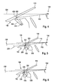
- FIG. 12 is a schematic illustration of a field of view display 100 as a combination of a windshield visual field display and a combiner visual field display according to an embodiment of the present invention.
- the visual field display 100 may be a combination of a variant of an in Fig. 2 and one in Fig. 3 displayed field of view 100 act.
- the field of view display 100 comprises a device 106 for providing and a device 108 for redirecting.
- the means 106 for providing has a first imager 224, a second imager 538 and a mirror 226.
- the mirror 226 is representative of an optical module.
- the optical path of the light beams emanating from the imagers is represented by the optical axes 110, 112 in the figure.
- the diverter 108 comprises a portion of the windshield 118 as a projection surface and a combiner 332 in the lens root of the windshield 118.
- the image provided by the first imager 224 is displayed along the first optical axis 110 via the mirror 226 and a portion of the windshield 118 as a projection surface to the viewer 104 as a virtual image 230 in front of the windshield.
- the image provided by the second imager 538 is displayed to the viewer 104 as a virtual image 230 via the combiner 332 along the second optical axis 112.
- Fig. 5 12 shows a variant of a field of view display 100 in which the means for redirecting comprises a combiner 332 and a portion of the windshield 118 of the vehicle as a projection surface.
- means 108 for diverting comprises two combiners 332 or alternatively at least a portion of windshield 118.
- the means 106 for providing the in Fig. 5 The visual field display 100 shown has a first imager 224 and a second imager 538 and a mirror 226. In alternative embodiments, not shown here, the means 106 for providing comprises an imager 224 and a mirror 226. A corresponding embodiment is shown in FIG Fig. 7 explained in more detail.
- the means 108 for redirecting the projection may be configured to display the first image and / or the second image as a contact-analogous display for the viewer 104.
- a variant of the in Fig. 5 Viewing field 100 displayed around a contact-analogue field of view display (AR-HUD) with an additional combiner visual field display (combiner HUD).
- AR-HUD contact-analogue field of view display
- combiner visual field display combiner HUD
- the advantage is that vehicle-specific information such as speed, turn signal display, etc. can be displayed via the combiner visual field display and driving scene related information such as ACC bar, marking of a pedestrian or predictive vehicle, information of the navigation system, via the contact-analogue visual field display or AR hud look.
- the corresponding imagers 224, 538 are designed either as backlit liquid crystal displays or as projection imagers based on an image projector and a scattering surface, or a combination of both variants.
- FIG. 12 shows a schematic representation of a visual field display 100 as a combination of a visual field display with a separate, transparent holographic element projection display according to an exemplary embodiment of the present invention.
- the visual field display 100 may be a combination of a variant of an in Fig. 2 and one in Fig. 4 displayed field of view 100 act.
- the means 106 for providing comprises a first imager 224, a second imager 538 and a mirror 226. As already stated, the mirror 226 in the schematic representation represents a representative of an optical module.
- the holographic-optical element 436 is formed as a holographic lens 434.
- a field of view display 100 with integrated or additional holographic-optical projection display shown is located in the area of the lens root.
- the space is compared to a visual field display or contact-analogue field of view as in the variant Fig. 5 not enlarged.
- the field of view which can be used to display information, widens considerably, and care must be taken to ensure that the image fields do not interfere with one another.
- the field of view can be extended by adding a holographic-optical projection display (HOE: holographic-optical element), which is supplied with image information by a projector 224, 538.
- HOE holographic-optical element
- the image contents displayed on the holographic-optical projection display appear on the holographic-optical surface as a real image and not as a virtual image at a greater distance (> 1.8 m) as in a classical field of view display.
- the field of view typically 5 ° x 1.5 ° to 10 ° x 4 °
- a multiple (field of view of a holographic-optical projection display> 18 ° x 4 °).
- the installation space of the visual field display 100 does not change. It is an increased driving safety and increased ride comfort achieved because all the information displayed in the instrument cluster and central display on the holographic-optical projection display can be displayed at a lower angle to the driving and these are compared to the combination instrument in a slightly greater distance to the driver's eye, whereby the accommodation efforts by the viewer 104 can be reduced during reading.
- new ways of displaying image content are used: Information can be displayed in different levels, this can be used together with a perspective view to achieve depth-effective presentation. For example, vehicle-related information can be displayed on the holographic-optical projection display and environmental information with a classic Visual field display. Both functions are combined in one device.
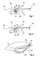
- FIG. 12 shows a schematic representation of a field of view display 100 as a combination of a single projector controlled field of view display with a separate transparent holographic element projection display according to one embodiment of the present invention.
- the diverter 108 includes a portion of the windshield 118 and a holographic-optical element 436.
- the provision 106 includes an imager 224 and an optics module including at least two mirrors 226 and another mirror 740.
- the imager 224 provides two images.
- the mirror 740 protrudes halfway into the beam path of the imager 224 and passes a picture half or partial picture over the two mirrors 226 and the partial area of the windshield 118 in the direction of the observer 104 Viewer 104 as a virtual image 230 in front of the windshield.
- the other half of the image or another partial image is not deflected by the mirror 740, but passes directly onto a holographic-optical projection surface 436 and appears to the viewer 104 as a real image.
- the mirror 740 is configured as an active optical element 740.
- the active optical element 740 is formed as a switchable mirror that alternately reflects, deflects, and reflects incident light rays and transmits incident light rays in a transparent-connected state.
- the active optical element 740 is arranged completely in the beam path of the imager 224 and, in a reflective state, guides the incident light or a first image over the optical elements or mirrors 226 onto the partial region of the windshield 118 formed as a projection surface and in one permeable state is passed to the incident light or the second image to the holographic-optical element 436.
- the reflective state and the transmissive state can be interchanged or, instead of the holographic-optical element 436, also a combiner 436 or with another embodiment described here in the figures can be combined.
- two systems may share an imager 224, that is, the image content of both systems is generated by a projector 224.
- each system may use a different imager area.
- the beam path of the image projector is hereby divided by means of a mirror 740 in the two paths (HUD and HOE display).
- an active optical element 740 for example, switchable mirror
- a frequency of> 120Hz could switch back and forth temporally sequentially between transmissive and reflective state with a frequency of> 120Hz.
- FIG. 12 is a schematic illustration of a field of view display 100 as a combination of a field of view display and a transparent holographic element projection display integrated into the windshield according to one embodiment of the present invention.
- the visual field display 100 may be an embodiment of the in Fig. 1 or Fig. 5 to Fig. 7 shown field of view 100 act.
- holographic-optical element 436 is arranged in the lens root of the windshield 101.
- means 108 for redirecting includes a portion of the windshield 118 and the holographic-optical element 436.
- the means 106 for providing comprises a first imager 224, a mirror 226, and a second imager 538.
- the first image provided by the first imager 224 becomes passed through the mirror 226 on the designed as a projection surface portion of the windshield 118 and shown as a virtual image 230 for the viewer 104 in front of the windshield 118.
- the second image provided by the second imager 538 is deflected towards the observer 104 via the holographic-optical element 436 and presents itself to the viewer 104 as a real image.
- the means 106 for providing is designed to provide the first image in a first wavelength range and the second image in a second wavelength range.
- the first wavelength range and the difference second wavelength range from each other.
- the first wavelength range extends from 380 nm to 580 nm and the second wavelength range from 580 nm to 720 nm.
- Fig. 8 is the combination of windshield field of view display (HUD or AR-HUD) and embedded in the windshield 118 embedded (or glued) holographic projection display in the area of the lens root.
- HUD windshield field of view display
- AR-HUD embedded in the windshield 118 embedded (or glued) holographic projection display in the area of the lens root.
- the areas used by the field of view display and the holographic-optical display to overlap, without image interference occurring.
- the topic of angle selectivity continues to run.
- the holographic pane root display can be designed over a large area and represent a variety of functions, along with the contact analog content displayed in the AR-HUD.
- both systems are mirrored over the windshield 118 (or visual field display integrated with the windshield), but utilize different areas on the windshield.
- both systems use the same area on the windshield 118.
- the field of view display uses the reflection on the windshield 118, while the image of the holographic-optical projection display is formed by the holographic layer. So that there is no mutual disruption of the systems here, the reconstruction angle of the holographic-optical display is chosen such that it differs from the reflection angle of the visual field display. If both systems share a projector 224, the separation of the systems by wavelength (for example, the field of view display uses a red representation and the holographic-optical system uses wavelengths of light in the range of green and / or blue).
- Fig. 9 shows a schematic representation of an autostereoscopic holographic projection display.
- a holographic pane root display 436 in an analogous manner as the combination of visual field display and holographic-optical projection display (see above), such a solution can be used to display image contents in different depth levels and combine them with additional image contents displayed on the holographic-optical projection display.
- the latter are relatively close to the driver's eye (typically ⁇ 1m) and therefore can not be displayed by means of the autostereoscopic display without a driver inconvenient inconsistency between the depth indications of accommodation and convergence.
- the holographic projection display 436 to the autostereoscopic visual field display, the depth range usable for the display of image contents is increased.
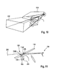
- FIG. 12 is a schematic diagram of a visual field display 100 as a combination of an autostereoscopic holographic projection display and an autostereoscopic visual field display according to an embodiment of the present invention. So shows Fig. 10 a stereo field of view display with additional (stereoscopic) holographic-optical projection display integrated into the windshield 118.
- means 106 for providing is configured to generate at least one autostereoscopic image.
- the deflecting device 108 is designed to be autostereoscopic.
- the holographic-optical projection display can also be designed to be autostereoscopic.
- FIG. 11 shows a schematic representation of a visual display 100 with an embedded in the windshield holographic-optical element according to an embodiment of the present invention.
- a device 106 for providing comprises two imagers 224, 538.
- a device 108 for diverting has a holographic-optical element 436.
- the images provided by the imagers 224, 538 are directed via the holographic-optical element 436 in the direction of the eye of the observer 104. In this case, the image emanating from the first imager 224 presents itself to the viewer 104 as a real image.
- the second image provided by the second imager 538 represents the viewer 104 as a virtual image 230.
- the holographic-optical element 436 has a Spreading disc function 1146 and a concave mirror function 1148 on.
- the diffuser lens function 1146 and the concave mirror function 1148 selectively operate depending on the angle of the light rays occurring. This can be referred to as dependent on an angle of incidence or reconstruction angle.
- the holographic-optical element has different optical properties depending on the angle of incidence between the light beams or the optical axis of the incident light beams.
- the means 108 for redirecting comprises a holographic-optical element 436, wherein the holographic-optical element 436 has a concave mirror function 1148 for a first reconstruction angle and a lens function 1146 for a second reconstruction angle different from the first reconstruction angle.
- FIG. 11 an embodiment is shown in which an embedded in the windshield 118 holographic-optical element 436 performs two optical functions. First, it creates the scatter function for the transparent holographic-optical projection display. On the other hand, it is also the last optical element of the visual field display system and realizes, for example, a concave mirror function. In this case, the last in "last optical element" refers to an arrangement starting from the image generator as the light source and the eye of the observer 104 as the detector.
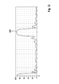
- Fig. 12 the result of a simulation for a simple holographic deflection element is shown by way of example. It can be seen clearly the steep drop in the diffraction efficiency, if the angle of incidence from the target angle (in this example 56 °) deviates.
- the diffraction efficiency is already below 1%.
- suitable choice of the reconstruction angle taking into account the angular selectivity of the holographic-optical element 436, therefore, different optical functions can be realized in one that do not interfere.
- the independence of the two optical functions can also be achieved by utilizing the wavelength selectivity.
- FIG. 10 is a graph showing a simulation of a diffraction efficiency of a holographic-optical element according to an embodiment of the present invention.
- the holographic-optical element can be a holographic-optical element 436 provided with the reference numeral 436 in the preceding figures.
- the abscissa represents the spherical angle theta and the ordinate shows an effectivity of the reflection in percent.
- the curve 1250 has a maximum at 0 ° and at 56.7 °. In this case, a region of high reflection extends in a range from 0 ° to approximately 4 °, and a further region of high reflection extends in a range of 52 ° to 60 °. At all other angles, the reflection is below 20%.
- FIG. 12 shows a flow chart of a method 1300 for displaying image information in two independent images for a vehicle according to an exemplary embodiment of the present invention.
- the method 1300 for displaying image information in two independent images for a vehicle includes a step 1310 of providing a first image of the two independent images in a first optical axis and a second image of the two independent images in a second optical axis at least partially different from the first optical axis and a step 1320 of redirecting a projection of the first image and / or a projection of the second image, wherein the means for deflecting is formed as at least a partially transparent projection surface which is arranged in the optical axis of the first image and / or in the optical axis of the second image, wherein the projection of the first image along the first optical axis directed towards the viewer and wherein the projection of the second image along the second optical axis is directed towards the viewer.
- FIG. 12 shows a flowchart of a method 1400 for producing a visual field display for a vehicle for displaying image information in two independent images for a viewer according to an exemplary embodiment of the present invention.
- the visual field display may be an exemplary embodiment of a visual field display 100 described in the preceding figures.
- the method 1400 for producing a visual field display for a vehicle for displaying image information in two independent images for a viewer comprises a step 1410 of providing means for providing a first image of the two independent images in a first optical axis and a second image of the first image two independent images in one of the first optical axis at least partially different second optical axis and a means for deflecting a projection of the first image and / or a projection of the second image, wherein the means for deflecting is formed as at least a partially transparent projection surface and a Step 1420 of arranging the means for providing and the means for redirecting, such that the means for redirecting in the optical axis of the first image and / or arranged in the optical axis of the second image, wherein the projection d the first image is directed along the first optical axis in the direction of the observer and wherein the projection of the second image along the second optical axis is directed in the direction of the observer.
- an exemplary embodiment comprises a "and / or" link between a first feature and a second feature, then this is to be read so that the embodiment according to one embodiment, both the first feature and the second feature and according to another embodiment either only first feature or only the second feature.
Abstract
Die Erfindung betrifft eine Blickfeldanzeige (100) für ein Fahrzeug (102) zum Darstellen von Bildinformationen in zwei unabhängigen Bildern für einen Betrachter (104). Die Blickfeldanzeige (100) umfasst eine eine Einrichtung (106) zum Bereitstellen von einem ersten Bild der zwei unabhängigen Bilder in einer ersten optischen Achse (110) und von einem zweiten Bild der zwei unabhängigen Bilder in einer von der ersten optischen Achse (110) zumindest abschnittsweise verschiedenen zweiten optischen Achse (112) sowie eine Einrichtung (108) zum Umlenken einer Projektion des ersten Bildes und/oder einer Projektion des zweiten Bildes, wobei die Einrichtung (108) zum Umlenken als zumindest eine teilweise transparente Projektionsfläche ausgebildet ist, die in der ersten optischen Achse (110) des ersten Bildes und/oder in der zweiten optischen Achse (112) des zweiten Bildes angeordnet ist, wobei die Projektion des ersten Bildes entlang der ersten optischen Achse (110) in Richtung des Betrachters gelenkt wird und wobei die Projektion des zweiten Bildes entlang der zweiten optischen Achse (112) in Richtung des Betrachters (104) gelenkt wird.The invention relates to a visual field display (100) for a vehicle (102) for displaying image information in two independent images for a viewer (104). The field of view display (100) comprises means (106) for providing a first image of the two independent images in a first optical axis (110) and a second image of the two independent images in one of the first optical axis (110) at least in sections, different second optical axis (112) and means (108) for deflecting a projection of the first image and / or a projection of the second image, wherein the means (108) for deflecting at least a partially transparent projection surface is formed in the the first optical axis (110) of the first image and / or in the second optical axis (112) of the second image is arranged, wherein the projection of the first image along the first optical axis (110) is directed towards the viewer and wherein the projection of the second image along the second optical axis (112) in the direction of the viewer (104) is directed.
Description
Die vorliegende Erfindung bezieht sich auf eine Blickfeldanzeige für ein Fahrzeug zum Darstellen von Bildinformationen in zwei unabhängigen Bildern für einen Betrachter, auf ein Verfahren zum Herstellen und ein Verfahren zum Betreiben einer entsprechenden Blickfeldanzeige sowie auf ein entsprechendes Verfahren zum Darstellen von Bildinformationen in zwei unabhängigen Bildern für einen Betrachter.The present invention relates to a visual field display for a vehicle for displaying image information in two independent images to a viewer, to a method for manufacturing and a method for operating a corresponding visual field display and to a corresponding method for displaying image information in two independent images for a viewer.
Um Komfort und Sicherheit in modernen Fahrzeugen zu erhöhen, werden seit einiger Zeit immer mehr Fahrzeuge zusätzlich zum normalen Tachometer, im Folgenden auch als Kombigerät bezeichnet, mit einer Blickfeldanzeige ausgestattet. Blickfeldanzeigen werden auch als Head-up Displays (HUDs) bezeichnet. Blickfeldanzeigen sind Systeme, die kleine Flüssigkristallbildschirme (Abmessungen typischerweise 40mm (horizontal) x 20mm (vertikal)) über eine reflektiv ausgeführte Lupenoptik in ein über der Motorhaube schwebendes virtuelles Bild abbilden. Vorteilhaft bieten Blickfeldanzeigen eine erhöhte Fahrsicherheit durch schnelleres Ablesen aufgrund geringerem Winkel zum Fahrgeschehen und einen erhöhten Ablesekomfort durch reduzierte Akkommodationsanstrengungen der Augen eines Betrachters oder Fahrers.In order to increase comfort and safety in modern vehicles, more and more vehicles have been equipped with a visual field display in addition to the standard speedometer, also referred to below as combined unit. Visual field displays are also known as head-up displays (HUDs). Field of view displays are systems that image small liquid crystal displays (dimensions typically 40mm (horizontal) x 20mm (vertical)) via a magnifying glass optics into a virtual image floating above the hood. Advantageously, visual field displays offer increased driving safety through faster reading due to the lower angle to the driving situation and increased reading comfort due to reduced accommodation efforts of the eyes of a viewer or driver.
Blickfeldanzeigen sind auf dem Markt mit verschiedenen Technologien oder Eigenschaften. Sogenannte Combiner-HUDs sind Blickfeldanzeigen, die unabhängig von der Windschutzscheibe mittels einer separaten Combiner-Scheibe funktionieren. AR-HUDs sind Blickfeldanzeigen, die mittels kontaktanaloger Darstellung Bildinformationen mit der Straßenszene verschmelzen können. Dabei steht das AR auch für "Augmented Reality" oder "Erweiterte Realität". Weiterhin sind auf dem Consumermarkt LED-basierte Miniprojektoren verfügbar und werden in Zukunft auch Kfz-Anforderungen erfüllen können.Visual field displays are on the market with different technologies or features. So-called combiner HUDs are field of view displays that operate independently of the windshield using a separate combiner disc. AR-HUDs are field of view displays that use contact-analogue visual information with the street scene can merge. The AR stands for "augmented reality" or "augmented reality". Furthermore, LED-based mini-projectors are available on the consumer market and will be able to meet automotive requirements in the future.
In der
In
Vor diesem Hintergrund wird mit dem hier vorgestellten Ansatz ein Verfahren zum Darstellen von Bildinformationen in zwei unabhängigen Bildern für einen Betrachter, weiterhin eine Blickfeldeinrichtung für ein Fahrzeug zum Darstellen von Bildinformationen in zwei unabhängigen Bildern für einen Betrachter, das dieses Verfahren verwendet sowie schließlich ein Verfahren zum Betreiben einer Blickfeldeinrichtung für ein Fahrzeug und ein Verfahren zum Herstellen einer Blickfeldeinrichtung für ein Fahrzeug gemäß den Hauptansprüchen vorgestellt. Vorteilhafte Ausgestaltungen ergeben sich aus den jeweiligen Unteransprüchen und der nachfolgenden Beschreibung.Against this background, with the approach presented here, a method for displaying image information in two independent images for a viewer, a field of view device for a vehicle for displaying image information in two independent images for a viewer using this method, and finally a method for the Operating a field of view device for a vehicle and a method for producing a field of view device for a vehicle according to the main claims presented. Advantageous embodiments emerge from the respective subclaims and the following description.
Für Blickfeldanzeigen steht im Bereich der Armaturentafel eines Fahrzeugs nur ein sehr begrenzter Bauraum zur Verfügung. Gleichzeitig ist das Blickfeld oder die sogenannte Eyebox bei Blickfeldanzeigen sehr begrenzt. Das Blickfeld kann erweitert werden durch Hinzufügen einer zweiten Projektion oder Projektionsfläche. Dabei können zwei unterschiedliche Prinzipien für Blickfeldanzeigen kombiniert werden. Somit kann auch eine Vielfalt in der Blickfeldanzeige darstellbarer Funktionen im Vergleich zum Stand der Technik erweitert oder vergrößert werden.For field of view displays in the area of the instrument panel of a vehicle only a very limited space available. At the same time, the field of vision or the so-called eyebox is very limited in the field of view displays. The field of view can be expanded by adding a second projection or projection surface. Two different principles for visual field displays can be combined. Thus, a variety in the visual field displayable functions compared to the prior art can be extended or enlarged.
Es wird eine Blickfeldanzeige für ein Fahrzeug zum Darstellen von Bildinformationen in zwei unabhängigen Bildern für einen Betrachter vorgestellt, wobei die Blickfeldanzeige die folgenden Merkmale aufweist:
- eine Einrichtung zum Bereitstellen von einem ersten Bild der zwei unabhängigen Bilder in einer ersten optischen Achse und von einem zweiten Bild der zwei unabhängigen Bilder in einer von der ersten optischen Achse zumindest abschnittsweise verschiedenen zweiten optischen Achse; und
- eine Einrichtung zum Umlenken einer Projektion des ersten Bildes und/oder einer Projektion des zweiten Bildes, wobei die Einrichtung zum Umlenken als zumindest eine teilweise transparente Projektionsfläche ausgebildet ist, die in der optischen Achse des ersten Bildes und/oder in der optischen Achse des zweiten Bildes angeordnet ist, wobei die Einrichtung zum Umlenken ausgebildet ist, um die Projektion des ersten Bildes entlang der ersten optischen Achse in Richtung des Betrachters auszulenken und wobei die Einrichtung zum Umlenken ausgebildet ist, um die Projektion des zweiten Bildes entlang der zweiten optischen Achse in Richtung des Betrachters auszulenken.
- means for providing a first image of the two independent images in a first optical axis and a second image of the two independent images in a second optical axis at least partially different from the first optical axis; and
- a device for deflecting a projection of the first image and / or a projection of the second image, wherein the means for deflecting at least a partially transparent projection surface is formed in the optical axis of the first image and / or in the optical axis of the second image is arranged, wherein the means for deflecting is adapted to deflect the projection of the first image along the first optical axis in the direction of the observer and wherein the means for deflecting is adapted to the projection of the second image along the second optical axis in the direction of To deflect the viewer.
Ein Fahrzeug kann eine Blickfeldanzeige aufweisen. Bei dem Fahrzeug kann es sich um ein Kraftfahrzeug, insbesondere einen Personenkraftwagen oder ein Nutzfahrzeug handeln. Die Blickfeldanzeige kann die Funktionalität eines Head-up-Displays oder Combiner-HUDs umfassen. Somit können mit der Blickfeldanzeige Informationen in ein Sichtfeld eines Insassen eines Fahrzeugs eingeblendet werden. Beispielsweise können Informationen eines Fahrerassistenzsystems in die Sicht des Fahrers beziehungsweise Betrachters eingeblendet werden. Ferner kann die Blickfeldanzeige die Funktionalität eines Kombünstruments aufweisen, mit dem beispielsweise dem Fahrer weitere Informationen angezeigt werden können. Die vorgestellte Blickfeldanzeige ist ausgebildet, ein erstes Bild und ein zweites Bild darzustellen. Das erste Bild und das zweite Bild können voneinander unabhängig sein, das heißt das erste Bild und das zweite Bild können unterschiedliche Bildinformationen aufweisen. Dabei kann die Einrichtung zum Umlenken ausgebildet sein, dass zumindest eines der zwei unabhängigen Bilder für den Betrachter als ein virtuelles Bild erscheint. Somit kann das erste Bild und/oder das zweite Bild entstehen, und für den Betrachter wirken, als ob die über das Bild transportierten Daten vor dem Auge schweben würden. Die Einrichtung zum Umlenken kann eine Projektionsfläche umfassen, beispielsweise eine transparente Fläche beziehungsweise transluzente Fläche oder Fensterfläche, wobei die Blickfeldanzeige ausgebildet sein kann, die Projektionsfläche mit Licht zu beleuchten, sodass zumindest ein Teil des Lichts in die Augen eines Betrachters, der durch die transparente Fläche blickt, gespiegelt wird. Dabei kann das Licht die im ersten Bild und/oder zweiten Bild enthaltene Information transportieren.A vehicle may have a field of view display. The vehicle may be a motor vehicle, in particular a passenger car or a commercial vehicle. The field of view display may include the functionality of a head-up display or combiner HUD. Thus, the field of view display information in a field of view of an occupant of a vehicle can be displayed. For example, information from a driver assistance system can be displayed in the driver's or viewer's view. Furthermore, the visual field display can have the functionality of a combination instrument with which, for example, further information can be displayed to the driver. The presented visual field display is designed to display a first image and a second image. The first image and the second image may be independent of each other, that is, the first image and the second image may have different image information. In this case, the device for redirecting can be designed such that at least one of the two independent images appears to the viewer as a virtual image. Thus, the first image and / or the second image may arise and act to the viewer as if the data carried over the image would float in front of the eye. The means for deflecting may comprise a projection surface, for example a transparent surface or translucent surface or window surface, wherein the visual field display may be configured to illuminate the projection surface with light, so that at least one Part of the light in the eyes of a viewer who looks through the transparent surface, is mirrored. In this case, the light can transport the information contained in the first image and / or second image.
Die Einrichtung zum Umlenken kann einen Kombinierer umfassen. Die Einrichtung zum Umlenken kann einen Teilbereich einer Windschutzscheibe des Fahrzeugs als eine Projektionsfläche umfassen. In Fachkreisen ist der Kombinierer auch als Combiner bekannt. Ein Teilbereich der Windschutzscheibe kann speziell ausgerüstet sein oder spezielle Eigenschaften aufweisen, um für die Verwendung als Teil der Einrichtung zum Umlenken optimiert zu sein.The means for redirecting may comprise a combiner. The means for redirecting may comprise a portion of a windshield of the vehicle as a projection surface. In professional circles, the combiner is also known as a combiner. A portion of the windshield may be specially equipped or have special properties to be optimized for use as part of the diverter.
Ferner kann die Einrichtung zum Umlenken ein holografisch-optisches Element umfassen. So kann die Einrichtung zum Umlenken insbesondere eine holografische Streuscheibe umfassen. Ein holografisch-optisches Element wird auch oft mit seiner Abkürzung HOE bezeichnet. Unter einem holografisch-optischen Element oder holografisch-optischem Bauelement kann Element verstanden werden, dessen holografische Eigenschaften für die Optik der Blickfeldanzeige genutzt werden kann. So kann ein holografisch-optisches Bauelement Eigenschaften herkömmliche Linsen, Spiegel und ergänzend oder alternativ Prismen ersetzen. Holografisch-optische Elemente können spezielle Eigenschaften wie zum Beispiel die Selektivität der Farbe und des Einfallswinkels von Licht aufweisen; beispielsweise kann ein holografisch-optisches Element für einen bestimmten Einfallswinkel das Licht umlenken oder streuen, für die anderen Einfallswinkel aber vollkommen transparent sein. Vorteilhaft kann ein holografisch-optisches Element als planarer Spiegel, Hohlspiegel oder als Streuscheibe derart ausgebildet sein, dass das Licht so reflektiert wird, dass der Einfallswinkel anders als der Ausfallswinkel ist. So kann eine Reflexion mit einer Umlenkung oder Streuung (durch Beugung) des Lichtstrahls kombiniert werden.Further, the means for redirecting may comprise a holographic-optical element. Thus, the means for redirecting, in particular, comprise a holographic diffuser. A holographic-optical element is also often referred to by its abbreviation HOE. Under a holographic-optical element or holographic-optical device can be understood element whose holographic properties can be used for the optics of visual field display. Thus, a holographic-optical device can replace properties of conventional lenses, mirrors and, additionally or alternatively, prisms. Holographic-optical elements can have special properties such as the selectivity of the color and the angle of incidence of light; For example, a holographic-optical element may deflect or scatter the light for a given angle of incidence, but be completely transparent to the other angles of incidence. Advantageously, a holographic-optical element may be designed as a planar mirror, a concave mirror or a diffuser so that the light is reflected so that the angle of incidence is different than the angle of reflection. Thus, a reflection can be combined with a deflection or scattering (by diffraction) of the light beam.
Ferner kann die Einrichtung zum Bereitstellen einen ersten Bildgeber zum Bereitstellen des ersten Bildes und einen zweiten Bildgeber zum Bereitstellen des zweiten Bildes aufweisen. Alternativ kann die Einrichtung zum Bereitstellen einen ersten Bildgeber zum Bereitstellen des ersten Bildes und des zweiten Bildes und einen Spiegel umfassen. Günstig ist es auch, wenn die Einrichtung zum Bereitstellen einen ersten Bildgeber zum Bereitstellen des ersten Bildes, einen zweiten Bildgeber zum Bereitstellen des zweiten Bildes und einen Spiegel aufweist. Günstig ist es auch, wenn die Einrichtung zum Bereitstellen ein Optikmodul umfasst. Unter einem Optikmodul kann eine bildgebende Einheit wie ein TFT-Display, ein LCD-Display, eine Bildröhre oder ein Projektor verstanden werden.Furthermore, the means for providing may comprise a first imager for providing the first image and a second imager for providing the second image. Alternatively, the means for providing may include a first imager for providing the first image and the second image, and a mirror. It is also advantageous if the means for providing a first image generator for providing the first image, a second image generator for providing the second image and a mirror having. It is also favorable if the device for providing comprises an optical module. An optical module can be understood to mean an imaging unit such as a TFT display, an LCD display, a picture tube or a projector.
Die Einrichtung zum Bereitstellen kann einen Bildgeber aufweisen, der ausgebildet ist, das erste Bild und das zweite Bild bereitzustellen. Dabei kann der Bildgeber ausgebildet sein, das erste Bild und das zweite Bild zeitlich abwechselnd und ergänzend oder alternativ das erste Bild und das zweite Bild in zwei voneinander verschiedenen Teilbereichen einer Bildgeberfläche des Bildgebers bereitzustellen. Wenn die zwei Bilder zeitlich abwechselnd bereitgestellt werden, kann der Bildgeber mit einem Spiegel kombiniert werden, der abwechselnd transluzent und spiegelnd ausgebildet ist und synchron mit dem Bildgeber angesteuert werden kann. Wenn der Bildgeber die zwei Bilder in benachbarten Teilbereichen darstellt, kann ein Spiegel im Strahlengang derart angeordnet sein, dass eines der beiden Bilder von dem Spiegel abgelenkt wird und die dem Bild zugeordnete optische Achse einen verschiedenen Strahlengang durchläuft.The means for providing may include an imager configured to provide the first image and the second image. In this case, the imager can be designed to provide the first image and the second image alternately in time and additionally or alternatively the first image and the second image in two mutually different subareas of an imager surface of the imager. When the two images are alternately temporally provided, the imager can be combined with a mirror which is alternately translucent and specular and can be driven synchronously with the imager. If the imager displays the two images in adjacent partial areas, a mirror can be arranged in the beam path such that one of the two images is deflected by the mirror and the optical axis associated with the image passes through a different beam path.
Die Einrichtung zum Umlenken kann ein holografisch-optisches Element umfassen. Das holografisch-optische Element kann eine Hohlspiegelfunktion für eine Reflexion des ersten Bildes unter einem ersten Einfallswinkel und eine Streuscheibenfunktion für eine Reflexion des zweiten Bildes unter einem von dem ersten Einfallswinkel verschiedenen zweiten Einfallswinkel aufweisen. Der Einfallswinkel kann einen Winkel zwischen der ersten optischen Achse und/oder der zweiten optischen Achse und einer Oberfläche des holografisch-optischen Elements repräsentieren. Unter einem Einfallswinkel kann ein Rekonstruktionswinkel verstanden werden. So kann ein erstes Bild unter einem ersten Einfallswinkel auf das holografisch-optische Element projiziert werden und ein zweites Bild unter einem zweiten Einfallswinkel, der von dem ersten Einfallswinkel verschieden ist, auf das holografisch-optische Element projiziert werden, und beide Bilder werden in das identische Gesichtsfeld des Betrachters umgelenkt. So kann je nach Winkel der optischen Achse zu einer Oberfläche des holografisch-optischen Elementes dieses unterschiedliche optische Eigenschaften aufweisen.The means for redirecting may comprise a holographic-optical element. The holographic-optical element may have a concave mirror function for a reflection of the first image at a first angle of incidence and a diffuser function for a reflection of the second image at a second angle of incidence different from the first angle of incidence. The angle of incidence may represent an angle between the first optical axis and / or the second optical axis and a surface of the holographic-optical element. An angle of incidence can be understood as a reconstruction angle. Thus, a first image can be projected onto the holographic-optical element at a first angle of incidence, and a second image at a second angle of incidence other than the first angle of incidence projected onto the holographic-optical element, and both images become identical Visual field of the observer diverted. Thus, depending on the angle of the optical axis to a surface of the holographic-optical element have this different optical properties.
Ferner kann die Einrichtung zum Umlenken der Projektion ausgebildet sein, das erste Bild und ergänzend oder alternativ das zweite Bild als eine kontaktanaloge Anzeige für den Betrachter darzustellen. Unter einer kontaktanalogen Anzeige kann verstanden werden, dass kontaktanaloge Informationen oder kontaktanaloge Anzeigeelemente einem Fahrer oder Betrachter in seine aktuelle Sicht so eingeblendet werden, dass er das Gefühl hat, als seien sie fester Bestandteil der Umwelt.Furthermore, the means for deflecting the projection can be designed to display the first image and additionally or alternatively the second image as a contact-analogous display for the viewer. A contact-analogue display can be understood as meaning that contact-analogue information or contact-analogous display elements are superimposed on a driver or viewer in his current view in such a way that he has the feeling that they are an integral part of the environment.
Die Einrichtung zum Bereitstellen kann ausgebildet sein, das erste Bild in einem ersten Wellenlängenbereich und das zweite Bild in einem zweiten Wellenlängenbereich bereitzustellen. Dabei können sich der erste Wellenlängenbereich und der zweite Wellenlängenbereich voneinander unterscheiden. Beispielsweise können der erste Wellenlängenbereich und der zweite Wellenlängenbereich im sichtbaren Spektrum des Lichts liegen. Vorteilhaft kann zusammen mit einem holografisch-optischen Element, welches unterschiedliche Eigenschaften je nach Wellenlänge des auftreffenden Lichts aufweist, ein Aspekt der vorliegenden Erfindung umgesetzt werden.The means for providing may be configured to provide the first image in a first wavelength range and the second image in a second wavelength range. In this case, the first wavelength range and the second wavelength range may differ from each other. For example, the first wavelength range and the second wavelength range may be in the visible spectrum of the light. Advantageously, together with a holographic-optical element having different properties depending on the wavelength of the incident light, one aspect of the present invention can be implemented.
In einer Ausführungsform kann Einrichtung zum Bereitstellen ausgebildet sein, zumindest ein autostereoskopisches Bild zu erzeugen und ergänzend oder alternativ die Einrichtung zum Umlenken autostereoskopisch ausgelegt sein.In one embodiment, means for providing can be configured to generate at least one autostereoscopic image and, in addition or alternatively, the device for redirecting be designed to be autostereoscopic.
Es wird ein Verfahren zum Darstellen von Bildinformationen in zwei unabhängigen Bildern für ein Fahrzeug vorgestellt, wobei das Verfahren die folgenden Schritte umfasst:
- Bereitstellen von einem ersten Bild der zwei unabhängigen Bilder in einer ersten optischen Achse und von einem zweiten Bild der zwei unabhängigen Bilder in einer von der ersten optischen Achse zumindest abschnittsweise verschiedenen zweiten optischen Achse; und
- Umlenken einer Projektion des ersten Bildes und/oder einer Projektion des zweiten Bildes, wobei die Einrichtung zum Umlenken als zumindest eine teilweise transparente Projektionsfläche ausgebildet ist, die in der optischen Achse des ersten Bildes und/oder in der optischen Achse des zweiten Bildes angeordnet ist, wobei die Projektion des ersten Bildes entlang der ersten optischen Achse in Richtung des Betrachters gelenkt wird und wobei die Projektion des zweiten Bildes entlang der zweiten optischen Achse in Richtung des Betrachters gelenkt wird.
- Providing a first image of the two independent images in a first optical axis and a second image of the two independent images in a second optical axis at least partially different from the first optical axis; and
- Deflecting a projection of the first image and / or a projection of the second image, wherein the device for deflecting is formed as at least one partially transparent projection surface which is arranged in the optical axis of the first image and / or in the optical axis of the second image, the projection of the first image along the first optical axis is directed in the direction of the observer and wherein the projection of the second image along the second optical axis is directed in the direction of the observer.
Es wird ein Verfahren zum Herstellen einer Blickfeldanzeige für ein Fahrzeug zum Darstellen von Bildinformationen in zwei unabhängigen Bildern für einen Betrachter vorgestellt, wobei das Verfahren die folgenden Schritte umfasst:
- Bereitstellen einer Einrichtung zum Bereitstellen von einem ersten Bild der zwei unabhängigen Bilder in einer ersten optischen Achse und von einem zweiten Bild der zwei unabhängigen Bilder in einer von der ersten optischen Achse zumindest abschnittsweise verschiedenen zweiten optischen Achse sowie einer Einrichtung zum Umlenken einer Projektion des ersten Bildes und/oder einer Projektion des zweiten Bildes, wobei die Einrichtung zum Umlenken als zumindest eine teilweise transparente Projektionsfläche ausgebildet ist; und
- Anordnen der Einrichtung zum Bereitstellen und der Einrichtung zum Umlenken, derart, dass die Einrichtung zum Umlenken in der optischen Achse des ersten Bildes und/oder in der optischen Achse des zweiten Bildes angeordnet wird, sodass die Projektion des ersten Bildes entlang der ersten optischen Achse in Richtung des Betrachters gelenkt wird und wobei die Projektion des zweiten Bildes entlang der zweiten optischen Achse in Richtung des Betrachters gelenkt wird.
- Providing means for providing a first image of the two independent images in a first optical axis and a second image of the two independent images in a second optical axis at least partially different from the first optical axis, and means for redirecting a projection of the first image and / or a projection of the second image, wherein the device for deflecting is formed as at least a partially transparent projection surface; and
- Arranging the means for providing and the means for redirecting, such that the means for redirecting in the optical axis of the first image and / or arranged in the optical axis of the second image, so that the projection of the first image along the first optical axis in Direction of the viewer is directed and wherein the projection of the second image along the second optical axis is directed in the direction of the viewer.
Auch durch diese Ausführungsvariante der Erfindung in Form eines Verfahrens kann die der Erfindung zugrunde liegende Aufgabe schnell und effizient gelöst werden.Also by this embodiment of the invention in the form of a method, the object underlying the invention can be solved quickly and efficiently.
Der hier vorgestellte Ansatz wird nachstehend anhand der beigefügten Zeichnungen beispielhaft näher erläutert. Es zeigen:
- Fig. 1
- eine schematische Übersichtsdarstellung einer Blickfeldanzeige in einem Fahrzeug gemäß einem Ausführungsbeispiel der vorliegenden Erfindung;
- Fig. 2
- eine schematische Darstellung einer Windschutzscheiben-Blickfeldanzeige;
- Fig. 3
- eine schematische Darstellung einer Kombinierer-Blickfeldanzeige;
- Fig. 4
- eine schematische Darstellung einer transparenten Holografisches-Element-Projektionsanzeige als eine Scheibenwurzelanzeige;
- Fig. 5
- eine schematische Darstellung einer Blickfeldanzeige als eine Kombination einer Windschutzscheiben-Blickfeldanzeige und einer Kombinierer-Blickfeldanzeige gemäß einem Ausführungsbeispiel der vorliegenden Erfindung;
- Fig. 6
- eine schematische Darstellung einer Blickfeldanzeige als eine Kombination einer Blickfeldanzeige mit einer separaten, transparenten Holografisches-Element-Projektionsanzeige gemäß einem Ausführungsbeispiel der vorliegenden Erfindung;
- Fig. 7
- eine schematische Darstellung einer Blickfeldanzeige als eine Kombination von einer von einem einzigen Projektor angesteuerten Blickfeldanzeige mit einer separaten, transparenten Holografisches-Element-Projektionsanzeige gemäß einem Ausführungsbeispiel der vorliegenden Erfindung;
- Fig. 8
- eine schematische Darstellung einer Blickfeldanzeige als eine Kombination von einer Blickfeldanzeige und einer in die Windschutzscheibe integrierten transparenten Holografisches-Element-Projektionsanzeige gemäß einem Ausführungsbeispiel der vorliegenden Erfindung;
- Fig. 9
- eine schematische Darstellung einer autostereoskopischen holografischen Projektionsanzeige;
- Fig. 10
- eine schematische Darstellung einer Blickfeldanzeige als eine Kombination einer autostereoskopischen holografischen Projektionsanzeige und einer autostereoskopischen Blickfeldanzeige gemäß einem Ausführungsbeispiel der vorliegenden Erfindung;
- Fig. 11
- eine schematische Darstellung einer Blickfeldanzeige mit einem in die Windschutzscheibe eingebetteten holografisch-optischen Element gemäß einem Ausführungsbeispiel der vorliegenden Erfindung;
- Fig. 12
- ein Kurvenverlauf einer Simulation einer Beugungseffizienz eines holografisch-optischen Elements gemäß einem Ausführungsbeispiel der vorliegenden Erfindung;
- Fig. 13
- ein Ablaufdiagramm eines Verfahrens zum Darstellen von Bildinformationen in zwei unabhängigen Bildern für ein Fahrzeug gemäß einem Ausführungsbeispiel der vorliegenden Erfindung; und
- Fig. 14
- ein Ablaufdiagramm eines Verfahrens zum Herstellen einer Blickfeldanzeige für ein Fahrzeug zum Darstellen von Bildinformationen in zwei unabhängigen Bildern für einen Betrachter gemäß einem Ausführungsbeispiel der vorliegenden Erfindung.
- Fig. 1
- a schematic overview of a visual display in a vehicle according to an embodiment of the present invention;
- Fig. 2
- a schematic representation of a windshield visual field display;
- Fig. 3
- a schematic representation of a combiner visual field display;
- Fig. 4
- a schematic representation of a transparent holographic element projection display as a lens root display;
- Fig. 5
- a schematic representation of a visual field display as a combination of a windshield visual field display and a combiner visual field display according to an embodiment of the present invention;
- Fig. 6
- a schematic representation of a visual field display as a combination of a visual field display with a separate, transparent holographic element projection display according to an embodiment of the present invention;
- Fig. 7
- a schematic representation of a visual field display as a combination of a single-projector-driven visual field display with a separate, transparent holographic element projection display according to an embodiment of the present invention;
- Fig. 8
- a schematic representation of a visual field display as a combination of a visual display and a built-in windshield transparent holographic element projection display according to an embodiment of the present invention;
- Fig. 9
- a schematic representation of an autostereoscopic holographic projection display;
- Fig. 10
- a schematic representation of a visual field display as a combination of an autostereoscopic holographic Projection display and autostereoscopic visual field display according to an embodiment of the present invention;
- Fig. 11
- a schematic representation of a visual display with an embedded in the windshield holographic-optical element according to an embodiment of the present invention;
- Fig. 12
- a graph of a simulation of a diffraction efficiency of a holographic-optical element according to an embodiment of the present invention;
- Fig. 13
- a flowchart of a method for displaying image information in two independent images for a vehicle according to an embodiment of the present invention; and
- Fig. 14
- a flowchart of a method for producing a visual field display for a vehicle for displaying image information in two independent images for a viewer according to an embodiment of the present invention.
In der nachfolgenden Beschreibung günstiger Ausführungsbeispiele der vorliegenden Erfindung werden für die in den verschiedenen Figuren dargestellten und ähnlich wirkenden Elemente gleiche oder ähnliche Bezugszeichen verwendet, wobei auf eine wiederholte Beschreibung dieser Elemente verzichtet wird.In the following description of favorable embodiments of the present invention, the same or similar reference numerals are used for the elements shown in the various figures and similar acting, with a repeated description of these elements is omitted.
In dem gezeigten Ausführungsbeispiel ist die Blickfeldanzeige 100 mit einem Kombigerät 114 und einem Navigationssystem 116 verbunden. Das Kombigerät 114 und das Navigationssystem 116 stellen der Blickfeldanzeige 100 Informationen bereit, die in dem ersten Bild und/oder dem zweiten Bild für den Betrachter 104 sichtbar gemacht werden.In the exemplary embodiment shown, the
Die Blickfeldanzeige 100 nutzt in dem gezeigten Ausführungsbeispiel einen Teilbereich einer Windschutzscheibe 118 des Fahrzeugs 102 für die Einrichtung 108 zum Umlenken beziehungsweise als Projektionsfläche.In the exemplary embodiment shown, the
Die Blickfeldanzeige 100 ist zu einem Teil in einem Armaturenbrett 120 des Fahrzeugs 102 angeordnet. Das Armaturenbrett 120 ist aus Sicht des Betrachters 104 hinter einem Lenkrad 122 des Fahrzeugs 102 angeordnet. Die Einrichtung 106 zum Bereitstellen befindet sich für den Betrachter 104 verdeckt in einem Bereich hinter dem Armaturenbrett 120. Bei dem Armaturenbrett 120 handelt es sich um eine Anzeige- oder Instrumententafel mit Messanzeigern und Bedienungshebeln. Der Inhalt oder Wert von Anzeigeelementen der Armaturentafel 120 können in einem der Bilder der Blickfeldanzeige 100 für den Betrachter 104 dargestellt werden.The
Der nicht unbegrenzt verfügbare Bauraum im Armaturenbrett limitiert das Blickfeld einer Blickfeldanzeige, weswegen die Vielfalt darstellbarer Funktionen bei bekannten Systemen begrenzt ist.The not indefinitely available space in the dashboard limits the field of view of a visual field display, which is why the variety of representable functions is limited in known systems.
Gegenüber einer konventionellen Anzeige über eine Instrumententafel bietet eine eine solche Blickfeldanzeige 100 den Vorteil, dass der Betrachter 104 den Blick nicht von einer realen Verkehrssituation abwenden muss, um die mittels der Blickfeldanzeige 100 übermittelten Informationen zu erfassen. Ein weiterer Vorteil ist, dass der Betrachter 104 zwischen Fahrszene und Blickfeldanzeigen-Bildinhalt nicht refokussieren muss. Die Brennweite der einzelnen Augen des Betrachters 104 bleibt beim Ablesen nahezu auf unendlich. Die Blickfeldanzeige 100 umfasst in einem Ausführungsbeispiel die Funktionalität einer kontaktanalogen Blickfeldanzeige. Dabei können Bilder in die aktuelle Sicht eines Fahrzeuginsassen derart eingeblendet werden, als seien sie fester Bestandteil der Umwelt. Beispielsweise kann ein Navigationspfeil derart erscheinen, als läge er direkt auf der Straße. Die Projektionsfläche ist in dem gezeigten Ausführungsbeispiel transparent beziehungsweise transluzent ausgeführt, sodass neben der auf der Projektionsfläche dargestellten Bildinformation die in einer Blickrichtung hinter der Projektionsfläche liegende Bildinformation für den Betrachter 104 sichtbar ist. Die Projektionsfläche kann Informationen der Umwelt mit der Bildinformation, das heißt künstlich erzeugten Informationen, überlagern bzw. kombinieren. Auf die Projektionsfläche können von der Einrichtung 106 zum Bereitstellen ausgehende Lichtstrahlen geleitet werden. Eine Ausbreitung der von der Einrichtung 106 zum Bereitstellen ausgehenden Lichtstrahlen kann durch eine optische Achse 110, 112 definiert sein. Das erste Bild und das zweite Bild sind von der Einrichtung 106 zum Bereitstellen ausgehend über die Projektionsfläche in Richtung des Gesichtsfelds des Betrachters 104 darstellbar. Das Gesichtsfeld des Fahrzeuginsassen kann auch als Eyebox bezeichnet werden.Compared to a conventional display via an instrument panel, such a
Die in
Ein Combiner-HUD 100 oder eine Kombinierer-Blickfeldanzeige 100 ist in
In
Das von dem ersten Bildgeber 224 bereitgestellte Bild wird entlang der ersten optischen Achse 110 über den Spiegel 226 und einen Teilbereich der Windschutzscheibe 118 als Projektionsfläche dem Betrachter 104 als virtuelles Bild 230 vor der Windschutzscheibe dargestellt. Das von dem zweiten Bildgeber 538 bereitgestellte Bild wird über den Kombinierer 332 entlang der zweiten optischen Achse 112 dem Betrachter 104 als virtuelles Bild 230 dargestellt.
Die Einrichtung 106 zum Bereitstellen der in
Die Einrichtung 108 zum Umlenken der Projektion kann in einem Ausführungsbeispiel ausgebildet sein, das erste Bild und/oder das zweite Bild als eine kontaktanaloge Anzeige für den Betrachter 104 darzustellen.In one embodiment, the
Mit anderen Worten handelt es sich bei einer Variante der in
Mit anderen Worten ist in
Vorteilhaft kann im Vergleich zu einer einfachen, bekannten Blickfeldanzeige 100 das Blickfeld durch Hinzufügen einer holografisch-optischen Projektionsanzeige (HOE: holografisch-optisches Element), welche von einem Projektor 224, 538 mit Bildinformationen versorgt wird, erweitert werden. Die auf der holografisch-optischen Projektionsanzeige dargestellten Bildinhalte erscheinen auf der holografisch-optischen Oberfläche als reelles Bild und nicht als virtuelles Bild in größerer Entfernung (>1,8m) wie bei einer klassischen Blickfeldanzeige. Somit wird das Blickfeld (typisch 5°x 1,5° bis 10° x 4°) um ein Vielfaches vergrößert (Blickfeld einer holografisch-optischen Projektionsanzeige >= 18° x 4°). Dabei verändert sich der Bauraum der Blickfeldanzeige 100 nicht. Es wird eine erhöhte Fahrsicherheit und ein erhöhter Fahrkomfort erzielt, da alle im Kombiinstrument sowie Zentral-Display dargestellten Informationen auf der holografisch-optischen Projektionsanzeige in geringerem Winkel zum Fahrgeschehen dargestellt werden können und diese im Vergleich zum Kombünstrument auch in etwas größerer Entfernung zum Fahrerauge liegen, wodurch die Akkommodationsanstrengungen durch den Betrachter 104 beim Ablesen reduziert werden können. Vorteilhaft werden neuartige Möglichkeiten der Darstellung von Bildinhalten genutzt: Es können Informationen in verschiedenen Ebenen dargestellt werden, dies kann zusammen mit perspektivischer Darstellung genutzt werden, um tiefenwirksame Darstellung zu erreichen. Beispielsweise können fahrzeugzugehörige Informationen auf der holografisch-optischen Projektionsanzeige dargestellt werden und umgebungsabhängige Informationen mit einer klassischen Blickfeldanzeige angezeigt werden. Dabei sind beide Funktionalitäten in einer Vorrichtung vereint.Advantageously, in comparison to a simple, known
In einem alternativen Ausführungsbeispiel ist der Spiegel 740 als ein aktives optisches Element 740 ausgebildet. Beispielsweise ist das aktive optische Element 740 als ein schaltbarer Spiegel ausgebildet, der abwechselnd auf treffende Lichtstrahlen reflektiert, ablenkt bzw. spiegelt und in einem transparentgeschalteten Zustand auftreffende Lichtstrahlen hindurch lässt. Das aktive optische Element 740 ist in diesem Ausführungsbeispiel komplett im Strahlengang des Bildgebers 224 angeordnet und leitet in einem reflektierenden Zustand das auftreffende Licht bzw. ein erstes Bild über die optischen Elemente bzw. spiegelt 226 auf den als Projektionsfläche ausgebildeten Teilbereich der Windschutzscheibe 118 und in einem durchlässigen Zustand wird das auf treffende Licht bzw. das zweite Bild an das holografisch-optische Element 436 geleitet. In einer Variante können selbstverständlich der reflektierende Zustand und der durchlässige Zustand vertauscht werden oder anstelle des holografisch-optischen Elements 436 auch ein Kombinierer 436 oder mit einem anderen hier in den Figuren beschriebenem Ausführungsbeispiel kombiniert werden.In an alternative embodiment, the
Mit anderen Worten können sich zwei Systeme (beispielsweise eine klassische Blickfeldanzeige und eine holografisch-optische Projektionsanzeige) einen Bildgeber 224 teilen, das heißt, der Bildinhalt beider Systeme wird von einem Projektor 224 erzeugt. Hierbei kann jedes System beispielsweise eine andere Bildgeberfläche nutzen. Der Strahlengang des Bildprojektors wird hierbei mittels eines Spiegels 740 in die zwei Pfade (HUD- und HOE-Anzeige) aufgeteilt.In other words, two systems (eg, a classic field of view display and a holographic-optical projection display) may share an
Alternativ zu einem in
In einer Variante der in
In
Verschiedene Ausführungen sind möglich. In einem Ausführungsbeispiel werden die Bildinhalte beider Systeme über die Windschutzscheibe 118 (beziehungsweise eine in die Windschutzscheibe integrierte Blickfeldanzeige) eingespiegelt, aber nutzen unterschiedliche Bereiche auf der Windschutzscheibe. Alternativ nutzen beide Systeme den gleichen Bereich auf der Windschutzscheibe 118. Dabei nutzt die Blickfeldanzeige die Reflexion an der Windschutzscheibe 118, während das Bild der holografisch-optischen Projektionsanzeige durch die holografische Schicht entsteht. Damit es hier nicht zu einer gegenseitigen Störung der Systeme kommt, wird der Rekonstruktionswinkel der holografisch-optischen Anzeige so gewählt, dass er sich vom Reflexionswinkel der Blickfeldanzeige unterscheidet. Wenn beide Systeme sich einen Projektor 224 teilen, könnte die Trennung der Systeme mittels Wellenlänge (beispielsweise nutzt die Blickfeldanzeige eine rote Darstellung und das holografisch-optische System nutzt Wellenlängen des Lichts im Bereich von grün und/oder blau).Different versions are possible. In one embodiment, the image contents of both systems are mirrored over the windshield 118 (or visual field display integrated with the windshield), but utilize different areas on the windshield. Alternatively, both systems use the same area on the
Die Einrichtung 108 zum Umlenken umfasst ein holografisch-optisches Element 436, wobei das holografisch-optische Element 436 eine Hohlspiegelfunktion 1148 für einen ersten Rekonstruktionswinkel und eine Streuscheibenfunktion 1146 für einen von dem ersten Rekonstruktionswinkel verschiedenen zweiten Rekonstruktionswinkel aufweist.The means 108 for redirecting comprises a holographic-
Mit anderen Worten erfolgt eine Integration von zwei Funktionen, d.h. Streuscheibe und Hohlspiegel, in das holografisch-optische Element 436) in das HOE in der Windschutzscheibe 118. In
Die zwei optischen Funktionen können beide in ein einziges holografisch-optisches Element 436 aufgenommen werden oder durch zwei separate holografisch-optische Elemente 436 erzeugt werden, die aufeinander laminiert sind. Weiterhin können die zwei optischen Funktionen in unterschiedlichen Bereichen des holografisch-optischen Elements 436 liegen oder im selben Bereich des holografisch-optischen Elements 436 überlagert sein. Im letzteren Fall sind die zwei Funktionen dann durch unterschiedliche Rekonstruktionswinkel (=Einfallswinkel) zu separieren. Der Unterschied der Einfallswinkel sollte so groß sein, dass sich die Funktionen gegenseitig nicht stören. In
Die beschriebenen und in den Figuren gezeigten Ausführungsbeispiele sind nur beispielhaft gewählt. Unterschiedliche Ausführungsbeispiele können vollständig oder in Bezug auf einzelne Merkmale miteinander kombiniert werden. Auch kann ein Ausführungsbeispiel durch Merkmale eines weiteren Ausführungsbeispiels ergänzt werden.The embodiments described and shown in the figures are chosen only by way of example. Different embodiments may be combined together or in relation to individual features. Also, an embodiment can be supplemented by features of another embodiment.
Ferner können die hier vorgestellten Verfahrensschritte wiederholt sowie in einer anderen als in der beschriebenen Reihenfolge ausgeführt werden.Furthermore, the method steps presented here can be repeated as well as executed in a sequence other than that described.
Umfasst ein Ausführungsbeispiel eine "und/oder"-Verknüpfung zwischen einem ersten Merkmal und einem zweiten Merkmal, so ist dies so zu lesen, dass das Ausführungsbeispiel gemäß einer Ausführungsform sowohl das erste Merkmal als auch das zweite Merkmal und gemäß einer weiteren Ausführungsform entweder nur das erste Merkmal oder nur das zweite Merkmal aufweist.If an exemplary embodiment comprises a "and / or" link between a first feature and a second feature, then this is to be read so that the embodiment according to one embodiment, both the first feature and the second feature and according to another embodiment either only first feature or only the second feature.
Claims (11)
Applications Claiming Priority (1)
| Application Number | Priority Date | Filing Date | Title |
|---|---|---|---|
| DE102014200377.6A DE102014200377A1 (en) | 2014-01-13 | 2014-01-13 | A visual field display for a vehicle for displaying image information in two independent images to a viewer |
Publications (1)
| Publication Number | Publication Date |
|---|---|
| EP2894509A1 true EP2894509A1 (en) | 2015-07-15 |
Family
ID=51904814
Family Applications (1)
| Application Number | Title | Priority Date | Filing Date |
|---|---|---|---|
| EP14193987.6A Withdrawn EP2894509A1 (en) | 2014-01-13 | 2014-11-20 | Field of vision display for a vehicle for displaying image information in two independent images to a viewer |
Country Status (3)
| Country | Link |
|---|---|
| EP (1) | EP2894509A1 (en) |
| CN (1) | CN104777614A (en) |
| DE (1) | DE102014200377A1 (en) |
Cited By (7)
| Publication number | Priority date | Publication date | Assignee | Title |
|---|---|---|---|---|
| DE102016108878A1 (en) | 2016-05-13 | 2017-11-16 | Visteon Global Technologies, Inc. | Display unit and method for displaying information |
| WO2018206314A1 (en) | 2017-05-11 | 2018-11-15 | Saint-Gobain Glass France | Hud system and method for hud image generation |
| KR20210016699A (en) * | 2019-08-05 | 2021-02-17 | 주식회사 엘지화학 | Cover Dust Laminate and Head Up Display including the Cover Dust Laminate |
| JP2021039299A (en) * | 2019-09-05 | 2021-03-11 | 矢崎総業株式会社 | Display device for vehicle |
| CN112862980A (en) * | 2021-02-06 | 2021-05-28 | 西藏宁算科技集团有限公司 | Car arhud system based on Carla simulation platform |
| WO2022008119A1 (en) * | 2020-07-10 | 2022-01-13 | Bayerische Motoren Werke Aktiengesellschaft | Arrangement for reflection suppression in a windscreen display system, and windscreen display system |
| US11388376B2 (en) | 2018-04-03 | 2022-07-12 | Boe Technology Group Co., Ltd. | Display device and display control method |
Families Citing this family (13)
| Publication number | Priority date | Publication date | Assignee | Title |
|---|---|---|---|---|
| WO2017061039A1 (en) * | 2015-10-09 | 2017-04-13 | 日立マクセル株式会社 | Projection optical system and head-up display device |
| US20170161949A1 (en) * | 2015-12-08 | 2017-06-08 | GM Global Technology Operations LLC | Holographic waveguide hud side view display |
| DE102016005200A1 (en) | 2016-04-29 | 2017-11-02 | Audi Ag | Head-up display device with a holographic optical element for a motor vehicle |
| US11231586B2 (en) | 2017-04-28 | 2022-01-25 | Sony Corporation | Optical apparatus, image display apparatus, and display apparatus |
| CN110915205A (en) * | 2017-07-24 | 2020-03-24 | 三菱电机株式会社 | Display control device, display system, and display control method |
| DE102017219737A1 (en) * | 2017-11-07 | 2019-05-09 | Bayerische Motoren Werke Aktiengesellschaft | Visual field display device for a vehicle |
| CN108983423A (en) * | 2018-07-26 | 2018-12-11 | 京东方科技集团股份有限公司 | A kind of Binocular displays system and vehicle-mounted head-up-display system |
| CN108919495A (en) * | 2018-08-01 | 2018-11-30 | 张家港康得新光电材料有限公司 | A kind of 3D head-up-display system and its design method, automobile |
| DE102018221545A1 (en) * | 2018-12-12 | 2020-06-18 | Robert Bosch Gmbh | Projection device |
| TWI676823B (en) | 2018-12-26 | 2019-11-11 | 中強光電股份有限公司 | Head-up display apparatus |
| DE102019207898A1 (en) * | 2019-05-29 | 2020-12-03 | Robert Bosch Gmbh | Display device for a field of view display device for a vehicle, field of view display device, information display device or vehicle with a display device and method for operating a display device |
| DE102019210719B4 (en) * | 2019-07-19 | 2021-06-24 | Audi Ag | Display device with a screen element, motor vehicle, and method for operating a display device |
| DE102019211518B3 (en) * | 2019-08-01 | 2020-08-20 | Audi Ag | Display device for a motor vehicle and motor vehicle with a display device |
Citations (5)
| Publication number | Priority date | Publication date | Assignee | Title |
|---|---|---|---|---|
| WO1998035260A1 (en) | 1997-02-07 | 1998-08-13 | Daimler-Benz Ag | Holographic display screen for airplanes and vehicles |
| US20050154505A1 (en) * | 2003-12-17 | 2005-07-14 | Koji Nakamura | Vehicle information display system |
| US20090067057A1 (en) * | 2007-09-10 | 2009-03-12 | Microvision, Inc. | Buried numerical aperture expander having transparent properties |
| WO2009054709A2 (en) | 2007-10-22 | 2009-04-30 | Uab 'geola Digital' | Method for spatial images stream's observation and system implementing thereof |
| DE102012208697A1 (en) * | 2012-05-24 | 2013-11-28 | Bayerische Motoren Werke Aktiengesellschaft | Automotive head-up display |
Family Cites Families (2)
| Publication number | Priority date | Publication date | Assignee | Title |
|---|---|---|---|---|
| DE4445555C2 (en) * | 1993-12-24 | 2002-07-18 | Hyundai Autonet Co | Field of view display device for vehicles |
| DE102004050574B4 (en) * | 2004-10-15 | 2017-10-19 | Continental Automotive Gmbh | Device for displaying optical information by means of a virtual image, in particular in a motor vehicle |
-
2014
- 2014-01-13 DE DE102014200377.6A patent/DE102014200377A1/en not_active Withdrawn
- 2014-11-20 EP EP14193987.6A patent/EP2894509A1/en not_active Withdrawn
-
2015
- 2015-01-12 CN CN201510013124.8A patent/CN104777614A/en active Pending
Patent Citations (5)
| Publication number | Priority date | Publication date | Assignee | Title |
|---|---|---|---|---|
| WO1998035260A1 (en) | 1997-02-07 | 1998-08-13 | Daimler-Benz Ag | Holographic display screen for airplanes and vehicles |
| US20050154505A1 (en) * | 2003-12-17 | 2005-07-14 | Koji Nakamura | Vehicle information display system |
| US20090067057A1 (en) * | 2007-09-10 | 2009-03-12 | Microvision, Inc. | Buried numerical aperture expander having transparent properties |
| WO2009054709A2 (en) | 2007-10-22 | 2009-04-30 | Uab 'geola Digital' | Method for spatial images stream's observation and system implementing thereof |
| DE102012208697A1 (en) * | 2012-05-24 | 2013-11-28 | Bayerische Motoren Werke Aktiengesellschaft | Automotive head-up display |
Cited By (10)
| Publication number | Priority date | Publication date | Assignee | Title |
|---|---|---|---|---|
| DE102016108878A1 (en) | 2016-05-13 | 2017-11-16 | Visteon Global Technologies, Inc. | Display unit and method for displaying information |
| EP3246745A1 (en) | 2016-05-13 | 2017-11-22 | Visteon Global Technologies, Inc. | Display unit and method for representing information |
| WO2018206314A1 (en) | 2017-05-11 | 2018-11-15 | Saint-Gobain Glass France | Hud system and method for hud image generation |
| US11127216B2 (en) | 2017-05-11 | 2021-09-21 | Saint-Gobain Glass France | HUD system and method for HUD image generation |
| US11388376B2 (en) | 2018-04-03 | 2022-07-12 | Boe Technology Group Co., Ltd. | Display device and display control method |
| KR20210016699A (en) * | 2019-08-05 | 2021-02-17 | 주식회사 엘지화학 | Cover Dust Laminate and Head Up Display including the Cover Dust Laminate |
| JP2021039299A (en) * | 2019-09-05 | 2021-03-11 | 矢崎総業株式会社 | Display device for vehicle |
| WO2022008119A1 (en) * | 2020-07-10 | 2022-01-13 | Bayerische Motoren Werke Aktiengesellschaft | Arrangement for reflection suppression in a windscreen display system, and windscreen display system |
| CN112862980A (en) * | 2021-02-06 | 2021-05-28 | 西藏宁算科技集团有限公司 | Car arhud system based on Carla simulation platform |
| CN112862980B (en) * | 2021-02-06 | 2022-11-18 | 西藏宁算科技集团有限公司 | Car arhud system based on Carla simulation platform |
Also Published As
| Publication number | Publication date |
|---|---|
| CN104777614A (en) | 2015-07-15 |
| DE102014200377A1 (en) | 2015-07-16 |
Similar Documents
| Publication | Publication Date | Title |
|---|---|---|
| EP2894509A1 (en) | Field of vision display for a vehicle for displaying image information in two independent images to a viewer | |
| DE102011083662B4 (en) | Display apparatus for an occupant of a vehicle, vehicle and method for generating a display in an occupant's field of view | |
| DE19704740B4 (en) | Holographic screen and manufacturing process | |
| DE19930710C2 (en) | Image display system and method for vehicles | |
| DE102016111783B4 (en) | Display device for superimposing a virtual image in the field of view of a user | |
| EP3847499B1 (en) | Method for operating a field-of-vision display device for a motor vehicle | |
| DE112015002814T5 (en) | Display device for virtual images | |
| DE102005001973A1 (en) | Stereo combiner display for displaying image information e.g. text, in motor vehicle, has combiner arranged in field of view of vehicle driver, and image producing and separation units formed as transparent components of combiner | |
| EP3807708A1 (en) | Apparatus for generating a virtual image having a variable projection distance | |
| DE102014213355B4 (en) | Display unit with a head-up display device | |
| DE102012221310B4 (en) | Display arrangement for a motor vehicle, comprising an imager and a screen separator | |
| WO2014056702A2 (en) | Head-up display for a vehicle | |
| WO2014023658A2 (en) | Head-up display | |
| DE102011088794A1 (en) | Projection device e.g. combiner head-up display mounted near windshield of e.g. truck, has projection element to superimpose light signal in visible region, and illuminating device to illuminate peripheral portion of projection element | |
| DE102018221545A1 (en) | Projection device | |
| WO2018015496A1 (en) | Devices for data reflection | |
| DE102008004631A1 (en) | Cominer HUD with laser projects and special RGB coating | |
| DE102012208697A1 (en) | Automotive head-up display | |
| DE10302387A1 (en) | Head up display for motor vehicle divides display image into strips to provide reduction of parallax | |
| DE102016111119A1 (en) | Laser projection device and method for generating virtual images | |
| EP3296795A1 (en) | Method for displaying an image object in a vehicle on a display seen inside and outside the vehicle | |
| DE102019218627A1 (en) | Augmented reality head-up display | |
| DE102017208339A1 (en) | A projection display device for displaying a virtual display image in different display planes and a method for operating a projection display device | |
| DE102021113845A1 (en) | Vehicle-side display device | |
| DE102014221438A1 (en) | A visual field display device for projecting image information into a visual field of a vehicle occupant of a vehicle, and a method and control device for operating a visual field display device |
Legal Events
| Date | Code | Title | Description |
|---|---|---|---|
| PUAI | Public reference made under article 153(3) epc to a published international application that has entered the european phase |
Free format text: ORIGINAL CODE: 0009012 |
|
| 17P | Request for examination filed |
Effective date: 20141120 |
|
| AK | Designated contracting states |
Kind code of ref document: A1 Designated state(s): AL AT BE BG CH CY CZ DE DK EE ES FI FR GB GR HR HU IE IS IT LI LT LU LV MC MK MT NL NO PL PT RO RS SE SI SK SM TR |
|
| AX | Request for extension of the european patent |
Extension state: BA ME |
|
| R17P | Request for examination filed (corrected) |
Effective date: 20160115 |
|
| RBV | Designated contracting states (corrected) |
Designated state(s): AL AT BE BG CH CY CZ DE DK EE ES FI FR GB GR HR HU IE IS IT LI LT LU LV MC MK MT NL NO PL PT RO RS SE SI SK SM TR |
|
| 17Q | First examination report despatched |
Effective date: 20170131 |
|
| STAA | Information on the status of an ep patent application or granted ep patent |
Free format text: STATUS: THE APPLICATION IS DEEMED TO BE WITHDRAWN |
|
| 18D | Application deemed to be withdrawn |
Effective date: 20170811 |