EP2820968A1 - Case having non-insertion type interface for portable electronic device - Google Patents
Case having non-insertion type interface for portable electronic device Download PDFInfo
- Publication number
- EP2820968A1 EP2820968A1 EP13755333.5A EP13755333A EP2820968A1 EP 2820968 A1 EP2820968 A1 EP 2820968A1 EP 13755333 A EP13755333 A EP 13755333A EP 2820968 A1 EP2820968 A1 EP 2820968A1
- Authority
- EP
- European Patent Office
- Prior art keywords
- insertion type
- contact
- portable electronic
- electronic device
- magnetic coupling
- Prior art date
- Legal status (The legal status is an assumption and is not a legal conclusion. Google has not performed a legal analysis and makes no representation as to the accuracy of the status listed.)
- Withdrawn
Links
Images


Classifications
-
- H—ELECTRICITY
- H01—ELECTRIC ELEMENTS
- H01R—ELECTRICALLY-CONDUCTIVE CONNECTIONS; STRUCTURAL ASSOCIATIONS OF A PLURALITY OF MUTUALLY-INSULATED ELECTRICAL CONNECTING ELEMENTS; COUPLING DEVICES; CURRENT COLLECTORS
- H01R13/00—Details of coupling devices of the kinds covered by groups H01R12/70 or H01R24/00 - H01R33/00
- H01R13/62—Means for facilitating engagement or disengagement of coupling parts or for holding them in engagement
- H01R13/6205—Two-part coupling devices held in engagement by a magnet
-
- A—HUMAN NECESSITIES
- A45—HAND OR TRAVELLING ARTICLES
- A45C—PURSES; LUGGAGE; HAND CARRIED BAGS
- A45C11/00—Receptacles for purposes not provided for in groups A45C1/00-A45C9/00
-
- H—ELECTRICITY
- H01—ELECTRIC ELEMENTS
- H01R—ELECTRICALLY-CONDUCTIVE CONNECTIONS; STRUCTURAL ASSOCIATIONS OF A PLURALITY OF MUTUALLY-INSULATED ELECTRICAL CONNECTING ELEMENTS; COUPLING DEVICES; CURRENT COLLECTORS
- H01R11/00—Individual connecting elements providing two or more spaced connecting locations for conductive members which are, or may be, thereby interconnected, e.g. end pieces for wires or cables supported by the wire or cable and having means for facilitating electrical connection to some other wire, terminal, or conductive member, blocks of binding posts
- H01R11/11—End pieces or tapping pieces for wires, supported by the wire and for facilitating electrical connection to some other wire, terminal or conductive member
- H01R11/30—End pieces held in contact by a magnet
-
- A—HUMAN NECESSITIES
- A45—HAND OR TRAVELLING ARTICLES
- A45C—PURSES; LUGGAGE; HAND CARRIED BAGS
- A45C11/00—Receptacles for purposes not provided for in groups A45C1/00-A45C9/00
- A45C2011/002—Receptacles for purposes not provided for in groups A45C1/00-A45C9/00 for portable handheld communication devices, e.g. mobile phone, pager, beeper, PDA, smart phone
-
- H—ELECTRICITY
- H01—ELECTRIC ELEMENTS
- H01R—ELECTRICALLY-CONDUCTIVE CONNECTIONS; STRUCTURAL ASSOCIATIONS OF A PLURALITY OF MUTUALLY-INSULATED ELECTRICAL CONNECTING ELEMENTS; COUPLING DEVICES; CURRENT COLLECTORS
- H01R13/00—Details of coupling devices of the kinds covered by groups H01R12/70 or H01R24/00 - H01R33/00
- H01R13/02—Contact members
- H01R13/22—Contacts for co-operating by abutting
- H01R13/24—Contacts for co-operating by abutting resilient; resiliently-mounted
- H01R13/2407—Contacts for co-operating by abutting resilient; resiliently-mounted characterized by the resilient means
- H01R13/2414—Contacts for co-operating by abutting resilient; resiliently-mounted characterized by the resilient means conductive elastomers
Definitions
- the present invention relates to a case for a portable electronic device, and more particularly, to a case for a portable electronic device having a non-insertion type interface, whereby the case protects an outer side of the portable electronic device, an insertion type connector is inserted into an open type port of the portable electronic device and a non-insertion type port corresponding to the insertion type connector comes into non-insertion point contact with a non-insertion type connector of a peripheral device by using magnetism.
- portable electronic devices such as mobile phones, smartphones, or tablet personal computers (PCs)
- PCs personal computers
- Various units for protecting these portable electronic devices have been researched and developed due to their high prices and outer surface special processing thereof.
- various types of cases whereby a crack or scratch can be prevented from occurring due to contact between sides, rear surfaces, and edges of the portable electronic devices and other objects when the portable electronic devices are carried, or partial abrasion can be prevented from occurring due to user's hand grasp, the portable electronic devices are accommodated so as to protect various manipulation buttons or keys and exteriors of the portable electronic devices are protected, have been suggested.
- the portable electronic devices each include an open type port that enables connection of a connector of a peripheral device, such as a charging unit, to sides of the portable electronic device and charging of the portable electronic devices. Since the case has a through hole formed therein so that an insertion type connector of the peripheral device can be connected to the open type port through the through hole, a contact point terminal of the insertion type connector of the peripheral device physically comes into contact with a contact point terminal of the open type port such that the use, i.e., charging of the peripheral device can be performed.
- a peripheral device such as a charging unit
- the open type port of the portable electronic device generally has a structure of a concave groove shape and the insertion type connector of the peripheral device generally has a structure of a convex protrusion shape, damage or breakage in which physical contact point states of connectors become loose with reciprocal repeated combination and separation, a contact state of the contact point terminals becomes bad, or contact point terminals of the connectors may be bent or crooked according to a separation direction when the connectors are separated from each other.
- a printed circuit board (PCB) connected to the contact point terminal may be damaged with damage of the contact point terminal, and in this case, an economical loss in which the PCB needs to be replaced with a new one, may occur.
- PCB printed circuit board
- the open type port has always an open state, when foreign substances, such as dust and water, are introduced into the open type port, an unstable connection state may be established, and esthetic appeal of the portable electronic device may be lowered.
- the present invention provides a case for a portable electronic device having a non-insertion type interface, whereby the case protects an outer side of the portable electronic device, an insertion type connector is inserted into an open type port of the portable electronic device and a non-insertion type port corresponding to the insertion type connector comes into non-insertion point contact with a non-insertion type connector of a peripheral device by using magnetism.
- a portable electronic device including: a body in which the portable electronic device is accommodated; and a non-insertion type interface including an insertion type connector that is formed at one side of the body and that is inserted into an open type port formed at the portable electronic device and a non-insertion type port that is formed at the other side of the body so as to be electrically connected to the insertion type connector and that causes the non-insertion type connector of the peripheral device to come into surface contact with the non-insertion type port using magnetism.
- the non-insertion type port may include: a magnetic coupling member that is formed on a contact surface of the body and comes into surface contact with a magnetic coupling member provided on a contact surface of a non-insertion type connector using magnetism; and a contact terminal that is formed on the contact surface and causes a contact terminal of the non-insertion type connector to come into non-insertion point contact with the contact terminal when the magnetic coupling members are combined with each other using magnetism.
- the non-insertion type port may further include a guide that is formed on the contact surface and guides a guide of the non-insertion type connector so that non-insertion point contact of the contact terminals can be precisely performed in accordance with a magnetism combination of the magnetic coupling members.
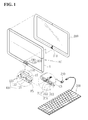
- FIG. 1 is a perspective view of a case for a portable electronic device having a non-insertion type interface according to an exemplary embodiment of the present invention
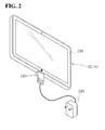
- FIG. 2 illustrates a state in which a non-insertion type connector of a peripheral device comes in contact with a non-insertion type port of the non-insertion type interface illustrated in FIG. 1
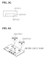
- FIGS. 3A through 3G illustrate the non-insertion type port of the non-insertion type interface of FIG. 1 and the non-insertion type connector of the peripheral device, according to various embodiments of the present invention
- FIGS. 4A through 4C illustrate a contact terminal provided on a printed circuit board (PCB) of the non-insertion type port and the non-insertion type connector illustrated in FIGS. 3A through 3G , according to an embodiment of the present invention.
- PCB printed circuit board
- a case EC for a portable electronic device having a non-insertion type interface includes a body A having a shape corresponding to an exterior of a portable electronic device 200 other than a display unit of the portable electronic device 200 so as to cover and protect the exterior of the portable electronic device 200, and a non-insertion type interface 100 including an insertion type connector 110 that is formed at one side of the body A, i.e., a lower side of the body A and that is inserted into an open type port 210 formed at the portable electronic device 200 and a non-insertion type port 120 that is formed at the other side of the body A, that is electrically connected to the insertion type connector 110 and that causes a non-insertion type connector 310 of a peripheral device 300 to come into surface contact with the non-insertion type port 120 using magnetism.
- the non-insertion type interface 100 of the case EC enables sealing of an open portion of the open type port 210 of the portable electronic device 200 using the insertion type connector 110 and sealing of the open portion using the non-insertion type port 120 connected to the insertion type connector 110 so that a problem that may occur when the open type port 210 has an open shape can be prevented.
- the non-insertion type connector 310 of the peripheral device 300 comes into contact with the non-insertion type port 120 using magnetism so that a conventional problem that may occur when the non-insertion type connector 310 having a protrusion shape of the peripheral device 300 is inserted into and comes into contact with the non-insertion type port 120 can be prevented.
- the body A may have a shape in which the body A may cover an exterior (except for the display unit) of the portable electronic device 200, such as a mobile phone, a smartphone, or a tablet personal computer (PC).
- the body A may be configured using various structures and assembling methods, whereby the body A is formed of a flexible material or causes a plurality of pieces to be connected as one body via a connection member and enables easy electrical point contact between the insertion type connector 110 of the non-insertion type interface 100 and the open type port 210 of the portable electronic device 200.
- the body A may serve as a bumper that protects the portable electronic device 200 from a shock.
- a lighting member such as a plurality of light emitting diode (LED) lamps that are connected to the insertion type connector 110 that will be described later and that emit light with power supplied from the portable electronic device 200, and a lighting diffusion member may be further provided at the body A so that the body A serves as a delicate lighting when the insertion type connector 110 is connected to the open type port 210 of the portable electronic device 200.
- the body A may further include accessories of various colors so that esthetic appeal of the portable electronic device 200 can be improved.
- the insertion type connector 110 is formed at one side of the body A, i.e., an insertion surface IS, to correspond to the open type port 210 of the portable electronic device 200 and thus is inserted into and connected to the open type port 210.
- the case EC includes a connector having a shape in which the insertion type connector 110 is to be inserted into the port.
- the non-insertion type port 120 is a connection port that is formed at the other side of the body A, i.e., a contact surface PS, to electrically correspond to the insertion type connector 110, that is provided to communicate with each other and that causes the non-insertion type connector 310 of the peripheral device 300 to come into surface contact with the non-insertion type port 120 using magnetism.
- the non-insertion type port 120 includes a magnetic coupling member 121 that is formed on the contact surface PS of the body A and comes into surface contact with a magnetic coupling member 311 provided on a contact surface CS of the non-insertion type connector 310 using magnetism, a contact terminal 122 that is formed on the contact surface PS and causes a contact terminal 312 of the non-insertion type connector 310 to come into non-insertion point contact with the contact terminal 122 when a magnetism combination of the magnetic coupling members 121 and 311 is performed, thereby enabling reciprocal transmission of power and data, and a guide 123 that is formed on the contact surface PS and causes a guide 313 of the non-insertion type connector 310 to be guided so that non-insertion point-contact of the contact terminals 122 and 312 with a magnetism combination of the magnetic coupling members 121 and 311 can be precisely performed.
- the non-insertion type connector 310 of the peripheral device 300 connected to the non-insertion type port 120 of the non-insertion type interface 100 of the case EC is a connector that causes the non-insertion type connector 310 to come into surface contact with the non-insertion type port 120 using magnetism.
- the non-insertion type connector 310 of the peripheral device 300 includes a magnetic coupling member 311 that is formed on the contact surface CS of a connector case and is coupled to the magnetic coupling member 121 using magnetism, a contact terminal 312 that is formed on the contact surface CS and causes the contact terminal 122 to come into non-insertion point contact with the contact terminal 312 when a magnetism combination of the magnetic coupling members 121 and 311 is performed, thereby enabling reciprocal transmission of power and data, and the guide 313 that is formed on the contact surface CS and is guided by the guide 123 so that non-insertion point-contact of the contact terminals 122 and 312 with a magnetism combination of the magnetic coupling members 121 and 311 can be precisely performed.
- the magnetic coupling member 121 is a coupling member that is formed on the contact surface PS of the body A and comes into surface contact with and is coupled to the magnetic coupling member 311 provided on the contact surface CS of the non-insertion type connector 310 using magnetism.
- the magnetic coupling member 121 may be placed on the contact surface PS of the body A to have various shapes and areas.
- the magnetic coupling member 121 may be provided to have an area corresponding to an area of the contact surface PS other than the contact terminal 122 and the guide 123, as illustrated in FIGS. 3A through 3G , or may be provided at one side of the contact terminal 122 and the guide 123 to have the area, or may be integrally formed with the guide 123.
- the magnetic coupling member 121 may be configured as one of a magnetic member and a magnetized member.
- the magnetic coupling member 121 may be at least one of a magnet, an electromagnet, a permanent magnet, a monopole magnetizer, an a multi-pole magnetizer.
- the magnetic coupling member 121 may include a metal or ferromagnetic substance that may be combined with the magnetic member using magnetism.
- the magnetic coupling member 121 may be a magnetic member having attraction with respect to the magnetic member so that the magnetic coupling member 121 and the magnetic coupling member 311 can be combined with each other using reciprocal magnetism, or a magnetized member.
- the magnetic coupling member 121 may be a magnetic member so that the magnetic coupling member 121 and the magnetic coupling member 311 can be combined with each other using reciprocal magnetism.
- the magnets are manufactured as vertical monopole, two-pole and four-pole magnetizers using equipment called a 'magnetizing yoke' without physically dividing the magnets and may have various numbers of polarities, or a metal substance may be placed at at least one of a rear portion, a right and left side portion, and a vertical side portion of each of the magnets so that magnetism can be improved using securing linearity of magnetism, or when a magnetism combination of the magnets is performed, only corresponding polarities of the magnets are combined so that, when the non-insertion type port 120 and the non-insertion type connector 310 need to come into point contact with each other with directivity, point contact in a reverse direction can be prevented.
- the magnetic coupling member 311 may be coupled to the magnetic coupling member 121 using magnetism.
- the contact terminal 122 may be integrally formed on a PCB provided at an inner side of the contact surface PS using a plating method or mounted on the PCB using a shape of a pin.
- the contact terminal 122 having various numbers may be disposed on the contact surface PS of the body A, as illustrated in FIGS. 3A through 3G .
- the contact terminal 122 may include a planar terminal 122a, of which an end has a planar or concave groove, and an elastic terminal 122b, of which an end rebounds and is inserted into the PCB with elasticity of a spring provided inside the elastic terminal 122b or only the end bends toward the PCB with elasticity.
- the planar terminal 122a has a structure in which the planar terminal 122a is recessed into an inner side of a through hole formed in the contact surface PS or corresponds to a plane of the through hole, and the elastic terminal 122b has a structure in which a part of the elastic terminal 122b protrudes toward an outer side of the through hole formed in the contact surface PS.
- the contact terminal 122 may be the elastic terminal 122b that enables reciprocal electrical point contact when the contact terminal 312 of the non-insertion type connector 310 of the peripheral device 300 is a planar terminal 312a.
- the contact terminal 122 may be the planar terminal 122a that enables reciprocal electrical point contact.
- the contact surface CS of the non-insertion type connector 310 elastically comes into point contact with the contact surface PS of the body A when the magnetic coupling members 121 and 311 for surface contact are combined with each other using magnetism, thereby enabling transmission of power and data between the non-insertion type port 120 and the non-insertion type connector 310.
- the PCB on which the contact terminal 122 of the non-insertion type port 120 is placed may be electrically connected to the PCB of the insertion type connector 110.
- the insertion type connector 110 is inserted into the open type port 210 of the portable electronic device 200, power and data can be transmitted.
- the contact terminal 122 may be formed on the PCB using various methods including assembling a material to which an electric current may be applied, i.e., the pin or an iron piece that is processed by etching and pressing, as well as the contact terminal 122 being integrally formed when a plating procedure for manufacturing the PCB is performed.
- the guide 123 is a guide member that guides the guide 313 of the non-insertion type connector 310 so that, when the non-insertion type connector 310 comes into surface contact with the contact surface PS, the guide 123 can be formed on the contact surface PS and non-insertion point contact between the contact terminals 122 and 312 with a magnetism combination of the magnetic coupling members 121 and 311 can be precisely performed as intended.
- the guide 123 may be placed on the contact surface PS of the body A to have various shapes and areas. For example, as illustrated in FIGS.
- the guide 123 may be formed to cover a plurality of contact terminals 122 with one group, or to include the magnetic coupling member 121 in a position of the contact surface PS, or one or a plurality of contact terminals 122 may be independently performed in the position of the contact surface PS.
- the guide 123 may be formed as one of an embossed guide that protrudes from the contact surface PS and an intagliated guide that is recessed into the contact surface PS.
- the guide 123 may be formed as an intagliated guide so that reciprocal insertion and combination can be performed.
- the guide 123 may be formed as an embossed guide so that reciprocal insertion and combination can be performed.
- the guide 123 of the non-insertion type port 120 guides the guide 313 of the non-insertion type connector 310 so that, when the non-insertion type connector 310 comes into surface contact with the contact surface PS, non-insertion point contact between the contact terminals 122 and 312 with a magnetism combination of the magnetic coupling members 121 and 311 can be precisely performed as intended.
- the non-insertion type connector 310 can be prevented from being unintentionally separated from a contact portion and simultaneously, the contact terminals 122 and 312 can be prevented from coming into point contact with each other in the reverse direction according to shapes.
- the guide 123 may also be provided on the contact surface PS to correspond to the exterior of the connector case on the contact surface CS of the non-insertion type connector 310.
- the contact surface CS of the non-insertion type connector 310 may be precisely placed on the contact surface PS of the non-insertion type port 120.
- the non-insertion type connector 310 of the peripheral device 300 is guided toward the non-insertion type port 120, comes into surface contact with the non-insertion type port 120 using magnetism and simultaneously, non-insertion point contact between the contact terminals 122 and 312 is performed.
- the non-insertion type port 120 can be easily connected to or separated from the non-insertion type connector 310, and unstable connection of terminals and damage of components that are conventional problems can be prevented.
- the non-insertion type connector 310 for the peripheral device 300 connected to the non-insertion type interface 100 of the case EC illustrated in FIG. 1 includes the magnetic coupling member 311, the contact terminal 312, and the guide 313 that are formed on the contact surface CS of the connector case, as described above.
- Each magnetic member or magnetized member, the planar terminal 312a, the elastic terminal 312b, the embossed guide, and the intagliated guide are configured in the same structures and the same methods as those of the magnetic member or magnetized member, the planar terminal 122a, the elastic terminal 122b, the embossed guide, and the intagliated guide of the non-insertion type port 120.
- the magnetic coupling member 311, the contact terminal 312, and the guide 313 formed on the contact surface CS of the connector case, and the magnetic coupling member 121, the contact terminal 122, and the guide 123 of the non-insertion type port 120 are configured so that their reciprocal opposed configurations, i.e., a magnetic member and a magnetized member, a planar terminal and an elastic terminal, and an embossed guide and an intagliated guide may correspond to each one configuration.
- the non-insertion type port 120 and the non-insertion type connector 310 may face each other and may be coupled to each other so that transmission of power and data between the peripheral device 300 and the portable electronic device 200 can be performed.
- the magnetic coupling members 121 and 311 may be provided at both or either of the non-insertion type port 120 and the non-insertion type connector 310.
- the non-insertion type connector 310 may be configured as a gender type that is separately connected to a terminal of an existing connector of the peripheral device 300 or an integral type that is connected directly to an end of an electric wire of the peripheral device 300 instead of the existing connector.
- the non-insertion type connector 310 may be configured in various shapes in which an existing terminal is fully accommodated and covered or is inserted into a rear side of the connector case.
- the gender type non-insertion type connector 310 may be connected to the connector case via a loss prevention unit, such as a loop that is provided at the electric wire of the peripheral device 300 so as to prevent loss.
- the portable electronic device 200 is accommodated in the body A of the case EC so that the insertion type connector 110 of the non-insertion type interface 100 is inserted into and connected to the open type port 210 formed at the portable electronic device 200.
- the portable electronic device 200 can be carried in a state in which the case EC accommodates the portable electronic device 200. Also, compared to the open type port 210 formed at the portable electronic device 200, the non-insertion type port 120 formed on the contact surface PS of the body A to correspond to the open type port 210 may be placed with a sense of sealing so that foreign substances can be prevented from being inserted into the non-insertion type port 120 and esthetic appeal of the portable electronic device 200 can be improved.
- the non-insertion type connector 310 of the peripheral device 300 comes into surface contact with the non-insertion type port 120 of the non-insertion type interface 100 placed on the contact surface PS of the body A.
- the magnetic coupling members 121 and 311 configured by being guided by the guide 123 of the non-insertion type port 120 are combined with each other using magnetism and thus, the contact terminals 122 and 312 configured on the magnetic coupling members 121 and 311 come into electrical point contact with each other so that the guide 313 of the non-insertion type connector 310 enables easy connection and separation to and from the non-insertion type connector 310 and thus a conventional problem that may occur when contact terminals are in an unstable connection state due to a long usage can be prevented.
- a non-insertion type connector of a peripheral device comes into non-insertion point contact with a non-insertion type port of a non-insertion type interface using magnetism in a state in which a portable electronic device is accommodated in a body of a case so that a non-insertion type interface insertion type connector can be inserted into and connected to an open type port of the portable electronic device so that connection of the peripheral device to the portable electronic device can be more conveniently and solidly performed and a stable contact state can be maintained.
- the portable electronic device can be carried in a state in which it is accommodated in the case so that esthetic appeal of the portable electronic device can be improved and simultaneously foreign substances can be prevented from being inserted into the open type port and the portable electronic device can be protected from an external shock.
Abstract
Description
- The present invention relates to a case for a portable electronic device, and more particularly, to a case for a portable electronic device having a non-insertion type interface, whereby the case protects an outer side of the portable electronic device, an insertion type connector is inserted into an open type port of the portable electronic device and a non-insertion type port corresponding to the insertion type connector comes into non-insertion point contact with a non-insertion type connector of a peripheral device by using magnetism.
- In general, portable electronic devices, such as mobile phones, smartphones, or tablet personal computers (PCs), have been necessarily used for communication in a modern society. Various units for protecting these portable electronic devices have been researched and developed due to their high prices and outer surface special processing thereof. In particular, various types of cases, whereby a crack or scratch can be prevented from occurring due to contact between sides, rear surfaces, and edges of the portable electronic devices and other objects when the portable electronic devices are carried, or partial abrasion can be prevented from occurring due to user's hand grasp, the portable electronic devices are accommodated so as to protect various manipulation buttons or keys and exteriors of the portable electronic devices are protected, have been suggested.
- Meanwhile, the portable electronic devices each include an open type port that enables connection of a connector of a peripheral device, such as a charging unit, to sides of the portable electronic device and charging of the portable electronic devices. Since the case has a through hole formed therein so that an insertion type connector of the peripheral device can be connected to the open type port through the through hole, a contact point terminal of the insertion type connector of the peripheral device physically comes into contact with a contact point terminal of the open type port such that the use, i.e., charging of the peripheral device can be performed.
- However, since the open type port of the portable electronic device generally has a structure of a concave groove shape and the insertion type connector of the peripheral device generally has a structure of a convex protrusion shape, damage or breakage in which physical contact point states of connectors become loose with reciprocal repeated combination and separation, a contact state of the contact point terminals becomes bad, or contact point terminals of the connectors may be bent or crooked according to a separation direction when the connectors are separated from each other.
- Also, when the open type port and the insertion type connector are coupled to each other in a reverse direction or an unreasonable force is applied to the open type port and the insertion type connector with a wrong using method, a printed circuit board (PCB) connected to the contact point terminal may be damaged with damage of the contact point terminal, and in this case, an economical loss in which the PCB needs to be replaced with a new one, may occur.
- Furthermore, since the open type port has always an open state, when foreign substances, such as dust and water, are introduced into the open type port, an unstable connection state may be established, and esthetic appeal of the portable electronic device may be lowered.
- The present invention provides a case for a portable electronic device having a non-insertion type interface, whereby the case protects an outer side of the portable electronic device, an insertion type connector is inserted into an open type port of the portable electronic device and a non-insertion type port corresponding to the insertion type connector comes into non-insertion point contact with a non-insertion type connector of a peripheral device by using magnetism.
- According to an aspect of the present invention, there is provided a case for a portable electronic device, including: a body in which the portable electronic device is accommodated; and a non-insertion type interface including an insertion type connector that is formed at one side of the body and that is inserted into an open type port formed at the portable electronic device and a non-insertion type port that is formed at the other side of the body so as to be electrically connected to the insertion type connector and that causes the non-insertion type connector of the peripheral device to come into surface contact with the non-insertion type port using magnetism.
- The non-insertion type port may include: a magnetic coupling member that is formed on a contact surface of the body and comes into surface contact with a magnetic coupling member provided on a contact surface of a non-insertion type connector using magnetism; and a contact terminal that is formed on the contact surface and causes a contact terminal of the non-insertion type connector to come into non-insertion point contact with the contact terminal when the magnetic coupling members are combined with each other using magnetism.
- The non-insertion type port may further include a guide that is formed on the contact surface and guides a guide of the non-insertion type connector so that non-insertion point contact of the contact terminals can be precisely performed in accordance with a magnetism combination of the magnetic coupling members.
-
-
FIG. 1 is a perspective view of a case for a portable electronic device having a non-insertion type interface according to an exemplary embodiment of the present invention; -
FIG. 2 illustrates a state in which a non-insertion type connector of a peripheral device comes in contact with a non-insertion type port of the non-insertion type interface illustrated inFIG. 1 ; -
FIGS. 3A through 3G illustrate the non-insertion type port of the non-insertion type interface ofFIG. 1 and the non-insertion type connector of the peripheral device, according to various embodiments of the present invention; and -
FIGS. 4A through 4C illustrate a contact terminal provided on a printed circuit board (PCB) of the non-insertion type port and the non-insertion type connector illustrated inFIGS. 3A through 3G , according to an embodiment of the present invention. - Hereinafter, the present invention will be described in detail by explaining exemplary embodiments of the invention with reference to the attached drawings.
-
FIG. 1 is a perspective view of a case for a portable electronic device having a non-insertion type interface according to an exemplary embodiment of the present invention,FIG. 2 illustrates a state in which a non-insertion type connector of a peripheral device comes in contact with a non-insertion type port of the non-insertion type interface illustrated inFIG. 1 ,FIGS. 3A through 3G illustrate the non-insertion type port of the non-insertion type interface ofFIG. 1 and the non-insertion type connector of the peripheral device, according to various embodiments of the present invention, andFIGS. 4A through 4C illustrate a contact terminal provided on a printed circuit board (PCB) of the non-insertion type port and the non-insertion type connector illustrated inFIGS. 3A through 3G , according to an embodiment of the present invention. - As illustrated in
FIGS. 1 through 4 , a case EC for a portable electronic device having a non-insertion type interface according to an exemplary embodiment of the present invention includes a body A having a shape corresponding to an exterior of a portableelectronic device 200 other than a display unit of the portableelectronic device 200 so as to cover and protect the exterior of the portableelectronic device 200, and anon-insertion type interface 100 including aninsertion type connector 110 that is formed at one side of the body A, i.e., a lower side of the body A and that is inserted into anopen type port 210 formed at the portableelectronic device 200 and anon-insertion type port 120 that is formed at the other side of the body A, that is electrically connected to theinsertion type connector 110 and that causes anon-insertion type connector 310 of aperipheral device 300 to come into surface contact with thenon-insertion type port 120 using magnetism. - That is, the
non-insertion type interface 100 of the case EC according to the present invention enables sealing of an open portion of theopen type port 210 of the portableelectronic device 200 using theinsertion type connector 110 and sealing of the open portion using thenon-insertion type port 120 connected to theinsertion type connector 110 so that a problem that may occur when theopen type port 210 has an open shape can be prevented. - Also, in the
non-insertion type interface 100 of the case EC, thenon-insertion type connector 310 of theperipheral device 300 comes into contact with thenon-insertion type port 120 using magnetism so that a conventional problem that may occur when thenon-insertion type connector 310 having a protrusion shape of theperipheral device 300 is inserted into and comes into contact with thenon-insertion type port 120 can be prevented. - Hereinafter, the case EC for the portable
electronic device 200 having thenon-insertion type interface 100 illustrated inFIG. 1 will be described in more detail. - The body A may have a shape in which the body A may cover an exterior (except for the display unit) of the portable
electronic device 200, such as a mobile phone, a smartphone, or a tablet personal computer (PC). The body A may be configured using various structures and assembling methods, whereby the body A is formed of a flexible material or causes a plurality of pieces to be connected as one body via a connection member and enables easy electrical point contact between theinsertion type connector 110 of thenon-insertion type interface 100 and theopen type port 210 of the portableelectronic device 200. - Here, the body A may serve as a bumper that protects the portable
electronic device 200 from a shock. A lighting member, such as a plurality of light emitting diode (LED) lamps that are connected to theinsertion type connector 110 that will be described later and that emit light with power supplied from the portableelectronic device 200, and a lighting diffusion member may be further provided at the body A so that the body A serves as a delicate lighting when theinsertion type connector 110 is connected to theopen type port 210 of the portableelectronic device 200. Also, the body A may further include accessories of various colors so that esthetic appeal of the portableelectronic device 200 can be improved. - The
insertion type connector 110 is formed at one side of the body A, i.e., an insertion surface IS, to correspond to theopen type port 210 of the portableelectronic device 200 and thus is inserted into and connected to theopen type port 210. When theopen type port 210 has the same shape as that of a charging port, the case EC includes a connector having a shape in which theinsertion type connector 110 is to be inserted into the port. - Here, structures of the
insertion type connector 110 and theopen type port 210 are well-known to one of ordinary skill in the art and thus a detailed description thereof will be omitted. - The
non-insertion type port 120 is a connection port that is formed at the other side of the body A, i.e., a contact surface PS, to electrically correspond to theinsertion type connector 110, that is provided to communicate with each other and that causes thenon-insertion type connector 310 of theperipheral device 300 to come into surface contact with thenon-insertion type port 120 using magnetism. Thenon-insertion type port 120 includes amagnetic coupling member 121 that is formed on the contact surface PS of the body A and comes into surface contact with amagnetic coupling member 311 provided on a contact surface CS of thenon-insertion type connector 310 using magnetism, acontact terminal 122 that is formed on the contact surface PS and causes acontact terminal 312 of thenon-insertion type connector 310 to come into non-insertion point contact with thecontact terminal 122 when a magnetism combination of themagnetic coupling members guide 123 that is formed on the contact surface PS and causes aguide 313 of thenon-insertion type connector 310 to be guided so that non-insertion point-contact of thecontact terminals magnetic coupling members - Here, the
non-insertion type connector 310 of theperipheral device 300 connected to thenon-insertion type port 120 of thenon-insertion type interface 100 of the case EC is a connector that causes thenon-insertion type connector 310 to come into surface contact with thenon-insertion type port 120 using magnetism. Thenon-insertion type connector 310 of theperipheral device 300 includes amagnetic coupling member 311 that is formed on the contact surface CS of a connector case and is coupled to themagnetic coupling member 121 using magnetism, acontact terminal 312 that is formed on the contact surface CS and causes thecontact terminal 122 to come into non-insertion point contact with thecontact terminal 312 when a magnetism combination of themagnetic coupling members guide 313 that is formed on the contact surface CS and is guided by theguide 123 so that non-insertion point-contact of thecontact terminals magnetic coupling members - The
magnetic coupling member 121 is a coupling member that is formed on the contact surface PS of the body A and comes into surface contact with and is coupled to themagnetic coupling member 311 provided on the contact surface CS of thenon-insertion type connector 310 using magnetism. Themagnetic coupling member 121 may be placed on the contact surface PS of the body A to have various shapes and areas. For example, themagnetic coupling member 121 may be provided to have an area corresponding to an area of the contact surface PS other than thecontact terminal 122 and theguide 123, as illustrated inFIGS. 3A through 3G , or may be provided at one side of thecontact terminal 122 and theguide 123 to have the area, or may be integrally formed with theguide 123. - Here, the
magnetic coupling member 121 may be configured as one of a magnetic member and a magnetized member. When themagnetic coupling member 121 is a magnetic member, themagnetic coupling member 121 may be at least one of a magnet, an electromagnet, a permanent magnet, a monopole magnetizer, an a multi-pole magnetizer. When themagnetic coupling member 121 is a magnetized member, themagnetic coupling member 121 may include a metal or ferromagnetic substance that may be combined with the magnetic member using magnetism. - Thus, when the
magnetic coupling member 311 of thenon-insertion type connector 310 of theperipheral device 300 is a magnetic member, themagnetic coupling member 121 may be a magnetic member having attraction with respect to the magnetic member so that themagnetic coupling member 121 and themagnetic coupling member 311 can be combined with each other using reciprocal magnetism, or a magnetized member. When themagnetic coupling member 311 is a magnetized member, themagnetic coupling member 121 may be a magnetic member so that themagnetic coupling member 121 and themagnetic coupling member 311 can be combined with each other using reciprocal magnetism. - Meanwhile, when the
magnetic coupling members non-insertion type port 120 and thenon-insertion type connector 310 need to come into point contact with each other with directivity, point contact in a reverse direction can be prevented. - Thus, according to the
magnetic coupling member 121 of thenon-insertion type port 120, when the contact surface CS of thenon-insertion type connector 310 comes into surface contact with the contact surface PS of the body A, themagnetic coupling member 311 may be coupled to themagnetic coupling member 121 using magnetism. - The
contact terminal 122 may be integrally formed on a PCB provided at an inner side of the contact surface PS using a plating method or mounted on the PCB using a shape of a pin. - Here, the
contact terminal 122 having various numbers may be disposed on the contact surface PS of the body A, as illustrated inFIGS. 3A through 3G . Also, as illustrated inFIGS. 4A through 4C , thecontact terminal 122 may include aplanar terminal 122a, of which an end has a planar or concave groove, and anelastic terminal 122b, of which an end rebounds and is inserted into the PCB with elasticity of a spring provided inside theelastic terminal 122b or only the end bends toward the PCB with elasticity. Theplanar terminal 122a has a structure in which theplanar terminal 122a is recessed into an inner side of a through hole formed in the contact surface PS or corresponds to a plane of the through hole, and theelastic terminal 122b has a structure in which a part of theelastic terminal 122b protrudes toward an outer side of the through hole formed in the contact surface PS. - Thus, the
contact terminal 122 may be theelastic terminal 122b that enables reciprocal electrical point contact when thecontact terminal 312 of thenon-insertion type connector 310 of theperipheral device 300 is aplanar terminal 312a. When thecontact terminal 312 is anelastic terminal 312b, thecontact terminal 122 may be theplanar terminal 122a that enables reciprocal electrical point contact. - Thus, according to the
contact terminal 122 of thenon-insertion type port 120, the contact surface CS of thenon-insertion type connector 310 elastically comes into point contact with the contact surface PS of the body A when themagnetic coupling members non-insertion type port 120 and thenon-insertion type connector 310. - In this case, the PCB on which the
contact terminal 122 of thenon-insertion type port 120 is placed, may be electrically connected to the PCB of theinsertion type connector 110. Thus, when theinsertion type connector 110 is inserted into theopen type port 210 of the portableelectronic device 200, power and data can be transmitted. - Meanwhile, the
contact terminal 122 may be formed on the PCB using various methods including assembling a material to which an electric current may be applied, i.e., the pin or an iron piece that is processed by etching and pressing, as well as thecontact terminal 122 being integrally formed when a plating procedure for manufacturing the PCB is performed. - The
guide 123 is a guide member that guides theguide 313 of thenon-insertion type connector 310 so that, when thenon-insertion type connector 310 comes into surface contact with the contact surface PS, theguide 123 can be formed on the contact surface PS and non-insertion point contact between thecontact terminals magnetic coupling members guide 123 may be placed on the contact surface PS of the body A to have various shapes and areas. For example, as illustrated inFIGS. 3A through 3G , theguide 123 may be formed to cover a plurality ofcontact terminals 122 with one group, or to include themagnetic coupling member 121 in a position of the contact surface PS, or one or a plurality ofcontact terminals 122 may be independently performed in the position of the contact surface PS. - Here, the
guide 123 may be formed as one of an embossed guide that protrudes from the contact surface PS and an intagliated guide that is recessed into the contact surface PS. When theguide 313 of thenon-insertion type connector 310 of theperipheral device 300 is an embossed guide, theguide 123 may be formed as an intagliated guide so that reciprocal insertion and combination can be performed. When theguide 313 of thenon-insertion type connector 310 is an intagliated guide, theguide 123 may be formed as an embossed guide so that reciprocal insertion and combination can be performed. Thus, when thenon-insertion type port 120 and thenon-insertion type connector 310 need to come into point contact with each other with directivity, point contact in a reverse direction can also be prevented. - Thus, the
guide 123 of thenon-insertion type port 120 guides theguide 313 of thenon-insertion type connector 310 so that, when thenon-insertion type connector 310 comes into surface contact with the contact surface PS, non-insertion point contact between thecontact terminals magnetic coupling members non-insertion type connector 310 can be prevented from being unintentionally separated from a contact portion and simultaneously, thecontact terminals - Meanwhile, the
guide 123 may also be provided on the contact surface PS to correspond to the exterior of the connector case on the contact surface CS of thenon-insertion type connector 310. Thus, the contact surface CS of thenon-insertion type connector 310 may be precisely placed on the contact surface PS of thenon-insertion type port 120. - Thus, according to the
non-insertion type port 120, thenon-insertion type connector 310 of theperipheral device 300 is guided toward thenon-insertion type port 120, comes into surface contact with thenon-insertion type port 120 using magnetism and simultaneously, non-insertion point contact between thecontact terminals non-insertion type port 120 can be easily connected to or separated from thenon-insertion type connector 310, and unstable connection of terminals and damage of components that are conventional problems can be prevented. - Meanwhile, the
non-insertion type connector 310 for theperipheral device 300 connected to thenon-insertion type interface 100 of the case EC illustrated inFIG. 1 includes themagnetic coupling member 311, thecontact terminal 312, and theguide 313 that are formed on the contact surface CS of the connector case, as described above. Each magnetic member or magnetized member, theplanar terminal 312a, theelastic terminal 312b, the embossed guide, and the intagliated guide are configured in the same structures and the same methods as those of the magnetic member or magnetized member, theplanar terminal 122a, theelastic terminal 122b, the embossed guide, and the intagliated guide of thenon-insertion type port 120. - Thus, the
magnetic coupling member 311, thecontact terminal 312, and theguide 313 formed on the contact surface CS of the connector case, and themagnetic coupling member 121, thecontact terminal 122, and theguide 123 of thenon-insertion type port 120 are configured so that their reciprocal opposed configurations, i.e., a magnetic member and a magnetized member, a planar terminal and an elastic terminal, and an embossed guide and an intagliated guide may correspond to each one configuration. Thus, thenon-insertion type port 120 and thenon-insertion type connector 310 may face each other and may be coupled to each other so that transmission of power and data between theperipheral device 300 and the portableelectronic device 200 can be performed. - In this case, the
magnetic coupling members non-insertion type port 120 and thenon-insertion type connector 310. - Also, the
non-insertion type connector 310 may be configured as a gender type that is separately connected to a terminal of an existing connector of theperipheral device 300 or an integral type that is connected directly to an end of an electric wire of theperipheral device 300 instead of the existing connector. When thenon-insertion type connector 310 is formed as the gender type, thenon-insertion type connector 310 may be configured in various shapes in which an existing terminal is fully accommodated and covered or is inserted into a rear side of the connector case. The gender typenon-insertion type connector 310 may be connected to the connector case via a loss prevention unit, such as a loop that is provided at the electric wire of theperipheral device 300 so as to prevent loss. - Meanwhile, in the present invention, when the
non-insertion type connector 310 comes into surface contact with thenon-insertion type port 120, contact surfaces are guided by theguides magnetic coupling members - Hereinafter, operations and effects of the case EC for the portable
electronic device 200 having thenon-insertion type interface 100 and thenon-insertion type connector 310 of theperipheral device 300 connected to the case EC illustrated inFIG. 1 will be described. - First, the portable
electronic device 200 is accommodated in the body A of the case EC so that theinsertion type connector 110 of thenon-insertion type interface 100 is inserted into and connected to theopen type port 210 formed at the portableelectronic device 200. - Thus, the portable
electronic device 200 can be carried in a state in which the case EC accommodates the portableelectronic device 200. Also, compared to theopen type port 210 formed at the portableelectronic device 200, thenon-insertion type port 120 formed on the contact surface PS of the body A to correspond to theopen type port 210 may be placed with a sense of sealing so that foreign substances can be prevented from being inserted into thenon-insertion type port 120 and esthetic appeal of the portableelectronic device 200 can be improved. - In this state, when the
peripheral device 300 is used, thenon-insertion type connector 310 of theperipheral device 300 comes into surface contact with thenon-insertion type port 120 of thenon-insertion type interface 100 placed on the contact surface PS of the body A. - In this case, the
magnetic coupling members guide 123 of thenon-insertion type port 120 are combined with each other using magnetism and thus, thecontact terminals magnetic coupling members guide 313 of thenon-insertion type connector 310 enables easy connection and separation to and from thenon-insertion type connector 310 and thus a conventional problem that may occur when contact terminals are in an unstable connection state due to a long usage can be prevented. - Thus, according to the present invention described above, a non-insertion type connector of a peripheral device comes into non-insertion point contact with a non-insertion type port of a non-insertion type interface using magnetism in a state in which a portable electronic device is accommodated in a body of a case so that a non-insertion type interface insertion type connector can be inserted into and connected to an open type port of the portable electronic device so that connection of the peripheral device to the portable electronic device can be more conveniently and solidly performed and a stable contact state can be maintained.
- Also, the portable electronic device can be carried in a state in which it is accommodated in the case so that esthetic appeal of the portable electronic device can be improved and simultaneously foreign substances can be prevented from being inserted into the open type port and the portable electronic device can be protected from an external shock.
- While the present invention has been particularly shown and described with reference to exemplary embodiments thereof, it will be understood by those of ordinary skill in the art that various changes in form and details may be made therein without departing from the spirit and scope of the present invention as defined by the following claims.
- According to the present invention, a non-insertion type connector of a peripheral device comes into non-insertion point contact with a non-insertion type port of a non-insertion type interface using magnetism in a state in which a portable electronic device is accommodated in a body of a case so that a non-insertion type interface insertion type connector can be inserted into and connected to an open type port of the portable electronic device so that connection of the peripheral device to the portable electronic device can be more conveniently and solidly performed and a stable contact state can be maintained.
- Also, the portable electronic device can be carried in a state in which it is accommodated in the case so that esthetic appeal of the portable electronic device can be improved and simultaneously foreign substances can be prevented from being inserted into the open type port and the portable electronic device can be protected from an external shock.
Claims (7)
- A case for a portable electronic device, comprising:a body A in which a portable electronic device 200 is accommodated; anda non-insertion type interface 100 comprising an insertion type connector 110 that is formed at one side of the body A and that is inserted into an open type port 210 formed at the portable electronic device 200 and a non-insertion type port 120 that is formed at the other side of the body A so as to be electrically connected to the insertion type connector 110 and that causes the non-insertion type connector 310 of the peripheral device 300 to come into surface contact with the non-insertion type port 120 using magnetism.
- The case for a portable electronic device of claim 1, wherein the non-insertion type port 120 comprises:a magnetic coupling member 121 that is formed on a contact surface PS of the body A and comes into surface contact with a magnetic coupling member 311 provided on a contact surface CS of a non-insertion type connector 310 using magnetism; anda contact terminal 122 that is formed on the contact surface PS and causes a contact terminal 312 of the non-insertion type connector 310 to come into non-insertion point contact with the contact terminal 122 when the magnetic coupling members 121 and 311 are combined with each other using magnetism.
- The case for a portable electronic device of claim 2, wherein the non-insertion type port 120 further comprises a guide 123 that is formed on the contact surface PS and guides a guide 313 of the non-insertion type connector 310 so that non-insertion point contact of the contact terminals 122 and 312 is capable of being precisely performed in accordance with a magnetism combination of the magnetic coupling members 121 and 311.
- The case for a portable electronic device of claim 2, wherein the magnetic coupling member 121 is configured as one of a magnetic member and a magnetized member, and when the magnetic coupling member 121 is a magnetic member, the magnetic coupling member 121 comprises at least one of a magnet, an electromagnet, a permanent magnet, a monopole magnetizer, and a multi-pole magnetizer, and when the magnetic coupling member 121 is a magnetized member, the magnetic coupling member 121 comprises a metal or ferromagnetic substance that is capable of being combined with the magnetic member using magnetism.
- The case for a portable electronic device of claim 2, wherein the contact terminal 122 is configured as one of a planar terminal 122a, of which an end has a planar or concave groove, and an elastic terminal 122b, of which an end has elasticity of a spring provided inside the elastic terminal 122b or only the end bends toward the PCB with elasticity, and the planar terminal 122a has a structure in which the planar terminal 122a is recessed into an inner side of a through hole formed in the contact surface PS or corresponds to a plane of the through hole, and the elastic terminal 122b has a structure in which a part of the elastic terminal 122b protrudes toward an outer side of the through hole formed in the contact surface PS.
- The case for a portable electronic device of claim 3, wherein the guide 123 is formed as one of an embossed guide that protrudes from the contact surface PS and an intagliated guide that is recessed into the contact surface PS.
- The case for a portable electronic device of claim 1, wherein a lighting member and a lighting diffusion member are further provided at the body A.
Applications Claiming Priority (2)
| Application Number | Priority Date | Filing Date | Title |
|---|---|---|---|
| KR1020120019725A KR101315688B1 (en) | 2012-02-27 | 2012-02-27 | Case with non-insertion type interface for potable electric apparatus |
| PCT/KR2013/001225 WO2013129794A1 (en) | 2012-02-27 | 2013-02-18 | Case having non-insertion type interface for portable electronic device |
Publications (2)
| Publication Number | Publication Date |
|---|---|
| EP2820968A1 true EP2820968A1 (en) | 2015-01-07 |
| EP2820968A4 EP2820968A4 (en) | 2015-08-26 |
Family
ID=49082945
Family Applications (1)
| Application Number | Title | Priority Date | Filing Date |
|---|---|---|---|
| EP13755333.5A Withdrawn EP2820968A4 (en) | 2012-02-27 | 2013-02-18 | Case having non-insertion type interface for portable electronic device |
Country Status (6)
| Country | Link |
|---|---|
| US (1) | US9147966B2 (en) |
| EP (1) | EP2820968A4 (en) |
| JP (1) | JP2015505270A (en) |
| KR (1) | KR101315688B1 (en) |
| CN (1) | CN103841853A (en) |
| WO (1) | WO2013129794A1 (en) |
Families Citing this family (15)
| Publication number | Priority date | Publication date | Assignee | Title |
|---|---|---|---|---|
| KR101326071B1 (en) * | 2012-02-27 | 2013-11-07 | (주)대한특수금속 | Tablet pc with non-insertion type port and cradle apparatus connecting thereof |
| KR101348932B1 (en) * | 2012-04-17 | 2014-01-08 | (주)대한특수금속 | USB memory apparatus with non-insertion type connecter and gender connecting thereof |
| US8894419B1 (en) * | 2012-08-14 | 2014-11-25 | Bby Solutions, Inc. | Magnetically connected universal computer power adapter |
| CN203445280U (en) * | 2013-07-26 | 2014-02-19 | 富士康(昆山)电脑接插件有限公司 | Electric connector |
| EP2846418A1 (en) * | 2013-09-06 | 2015-03-11 | Siemens Aktiengesellschaft | Subsea connection assembly |
| US10050658B2 (en) | 2014-02-24 | 2018-08-14 | National Products, Inc. | Docking sleeve with electrical adapter |
| WO2016017830A1 (en) * | 2014-07-29 | 2016-02-04 | (주)대한특수금속 | Case for portable electronic device |
| KR101597196B1 (en) * | 2014-08-07 | 2016-02-24 | (주)대한특수금속 | Case for portable electronic apparatus |
| KR101639330B1 (en) * | 2015-03-02 | 2016-07-14 | (주)대한특수금속 | Case for potable electric apparatus |
| CN105573430A (en) * | 2015-12-16 | 2016-05-11 | 联想(北京)有限公司 | Electronic equipment and manufacturing method of connection part |
| WO2018176630A1 (en) * | 2017-03-29 | 2018-10-04 | 华为技术有限公司 | Connector, electronic device and electronic apparatus |
| US10817689B2 (en) * | 2017-12-21 | 2020-10-27 | Datalogic IP Tech, S.r.l. | Systems and methods for a scan engine coupled to a finger mount |
| US11489350B2 (en) | 2019-12-23 | 2022-11-01 | National Products, Inc. | Cradle for mobile devices with resilient guides and methods of making and using |
| US11277506B2 (en) | 2020-05-26 | 2022-03-15 | National Products, Inc. | Cradles for mobile devices with one or more biasing tabs and methods of making and using |
| US11652326B2 (en) | 2021-04-30 | 2023-05-16 | National Products, Inc. | Dock with flexible locator pins and methods of making and using |
Family Cites Families (23)
| Publication number | Priority date | Publication date | Assignee | Title |
|---|---|---|---|---|
| JPH0645278U (en) * | 1991-06-06 | 1994-06-14 | 日本電気ホームエレクトロニクス株式会社 | Connector device |
| KR0133713Y1 (en) * | 1995-05-26 | 1999-01-15 | 김광호 | Memory card connecting device |
| ES2187260B1 (en) * | 2001-01-02 | 2004-09-16 | Ciba Specialty Chemicals Holding Inc. | PROCEDURE FOR THE EXTRUSION OF CHEMICAL PRODUCTS. |
| KR20020080766A (en) * | 2001-04-17 | 2002-10-26 | 신형진 | Apparatus for connecting power used magnetic |
| KR200265673Y1 (en) * | 2001-11-12 | 2002-02-25 | 송기석 | Auto joint magnet data jack of the cellular hands free |
| US6727477B1 (en) * | 2003-03-28 | 2004-04-27 | Lyu Jan Co., Ltd. | Temperature controller |
| KR200382247Y1 (en) * | 2005-01-22 | 2005-04-18 | (주)대한특수금속 | Non-insertion and contact type connector using magnet, mobile communication terminal connecting thereof and cellular phone charger |
| KR100736399B1 (en) * | 2005-01-22 | 2007-07-09 | (주)대한특수금속 | Non-insertion and contact type interface |
| US7351066B2 (en) * | 2005-09-26 | 2008-04-01 | Apple Computer, Inc. | Electromagnetic connector for electronic device |
| US7311526B2 (en) * | 2005-09-26 | 2007-12-25 | Apple Inc. | Magnetic connector for electronic device |
| US7467948B2 (en) * | 2006-06-08 | 2008-12-23 | Nokia Corporation | Magnetic connector for mobile electronic devices |
| US8170623B2 (en) * | 2006-11-17 | 2012-05-01 | Apple Inc. | Charging arrangement for electronic accessories |
| DE202008014989U1 (en) * | 2007-09-04 | 2009-01-15 | Magcode Ag | Device for producing a compound |
| US8367235B2 (en) * | 2008-01-18 | 2013-02-05 | Mophie, Inc. | Battery pack, holster, and extendible processing and interface platform for mobile devices |
| CN101515685A (en) * | 2008-02-21 | 2009-08-26 | 鸿富锦精密工业(深圳)有限公司 | Electric connector, and plug and socket thereof |
| US7828556B2 (en) * | 2008-03-31 | 2010-11-09 | Stanton Magnetics, Inc. | Audio magnetic connection and indexing device |
| JP5079617B2 (en) * | 2008-07-24 | 2012-11-21 | ジェット・Neko株式会社 | Solar power generator |
| DE102008038649A1 (en) * | 2008-08-12 | 2010-02-18 | Rosenberger Hochfrequenztechnik Gmbh & Co. Kg | Device for producing a compound |
| US7889494B2 (en) * | 2009-06-03 | 2011-02-15 | Urs Stampfli | Portable electronic device holster with guided docking station |
| CN202043757U (en) * | 2011-04-19 | 2011-11-23 | 钱懿 | Roller shutter type mobile phone protecting sleeve |
| US8920178B2 (en) * | 2011-12-01 | 2014-12-30 | Htc Corporation | Electronic apparatus assembly |
| KR101326071B1 (en) * | 2012-02-27 | 2013-11-07 | (주)대한특수금속 | Tablet pc with non-insertion type port and cradle apparatus connecting thereof |
| KR101348932B1 (en) * | 2012-04-17 | 2014-01-08 | (주)대한특수금속 | USB memory apparatus with non-insertion type connecter and gender connecting thereof |
-
2012
- 2012-02-27 KR KR1020120019725A patent/KR101315688B1/en not_active IP Right Cessation
-
2013
- 2013-02-18 CN CN201380003221.8A patent/CN103841853A/en active Pending
- 2013-02-18 JP JP2014553267A patent/JP2015505270A/en active Pending
- 2013-02-18 WO PCT/KR2013/001225 patent/WO2013129794A1/en active Application Filing
- 2013-02-18 US US14/342,853 patent/US9147966B2/en active Active
- 2013-02-18 EP EP13755333.5A patent/EP2820968A4/en not_active Withdrawn
Also Published As
| Publication number | Publication date |
|---|---|
| KR20130097982A (en) | 2013-09-04 |
| CN103841853A (en) | 2014-06-04 |
| US9147966B2 (en) | 2015-09-29 |
| JP2015505270A (en) | 2015-02-19 |
| KR101315688B1 (en) | 2013-10-10 |
| WO2013129794A9 (en) | 2014-10-16 |
| US20140362587A1 (en) | 2014-12-11 |
| EP2820968A4 (en) | 2015-08-26 |
| WO2013129794A1 (en) | 2013-09-06 |
Similar Documents
| Publication | Publication Date | Title |
|---|---|---|
| US9147966B2 (en) | Case for a portable electronic device having a non-insertion type interface | |
| US20140363988A1 (en) | Tablet pc having non-insertion type port and cradle connected to same | |
| US20150081944A1 (en) | Usb memory having non-insertion type connector and gender connected thereto | |
| EP2736127B1 (en) | An electronic device comprising a connector port and a cable connector device | |
| EP1865581B1 (en) | Mobile electronic device | |
| KR100736399B1 (en) | Non-insertion and contact type interface | |
| CN109995399B (en) | Connector and combination thereof | |
| KR101285253B1 (en) | Connector docking apparatus for potable electric apparatus and non-insertion type connector for peripheral apparatus connecting thereof | |
| WO2014168337A1 (en) | Magnetic interface | |
| KR101348933B1 (en) | Magnetic force type interface apparatus for electronic equipment | |
| JP2008171652A (en) | Small magnet connector | |
| KR101239215B1 (en) | Magnetic connector of portable electronic apparatus | |
| JP2013242976A (en) | Connector connection structure and electronic apparatus | |
| KR101326072B1 (en) | Notebook with non-insertion type port | |
| KR200382247Y1 (en) | Non-insertion and contact type connector using magnet, mobile communication terminal connecting thereof and cellular phone charger | |
| JP2012234627A (en) | Small magnet type connector | |
| KR200379697Y1 (en) | A connector for charging of a hand phone | |
| CN110336901B (en) | Mobile terminal and external device | |
| JP5832240B2 (en) | Magnetic connector | |
| CN219717316U (en) | Connector, connecting assembly and electronic equipment | |
| KR102318050B1 (en) | A Charging Connector Having a Structure of Magnet Coupling | |
| KR20140017363A (en) | Magnetic force type interface apparatus for electronic equipment | |
| KR20150043187A (en) | Interface connecting control apparatus |
Legal Events
| Date | Code | Title | Description |
|---|---|---|---|
| PUAI | Public reference made under article 153(3) epc to a published international application that has entered the european phase |
Free format text: ORIGINAL CODE: 0009012 |
|
| 17P | Request for examination filed |
Effective date: 20140714 |
|
| AK | Designated contracting states |
Kind code of ref document: A1 Designated state(s): AL AT BE BG CH CY CZ DE DK EE ES FI FR GB GR HR HU IE IS IT LI LT LU LV MC MK MT NL NO PL PT RO RS SE SI SK SM TR |
|
| AX | Request for extension of the european patent |
Extension state: BA ME |
|
| DAX | Request for extension of the european patent (deleted) | ||
| RA4 | Supplementary search report drawn up and despatched (corrected) |
Effective date: 20150728 |
|
| RIC1 | Information provided on ipc code assigned before grant |
Ipc: H01R 13/62 20060101ALI20150722BHEP Ipc: H01R 13/24 20060101ALI20150722BHEP Ipc: A45C 11/00 20060101AFI20150722BHEP Ipc: H01R 11/30 20060101ALI20150722BHEP |
|
| STAA | Information on the status of an ep patent application or granted ep patent |
Free format text: STATUS: THE APPLICATION HAS BEEN WITHDRAWN |
|
| 18W | Application withdrawn |
Effective date: 20160211 |