EP2469876B1 - Stereoscopic image display control apparatus and operation control method of the same - Google Patents
Stereoscopic image display control apparatus and operation control method of the same Download PDFInfo
- Publication number
- EP2469876B1 EP2469876B1 EP11795481.8A EP11795481A EP2469876B1 EP 2469876 B1 EP2469876 B1 EP 2469876B1 EP 11795481 A EP11795481 A EP 11795481A EP 2469876 B1 EP2469876 B1 EP 2469876B1
- Authority
- EP
- European Patent Office
- Prior art keywords
- stereoscopic
- stereoscopic image
- image
- blurring
- parallax
- Prior art date
- Legal status (The legal status is an assumption and is not a legal conclusion. Google has not performed a legal analysis and makes no representation as to the accuracy of the status listed.)
- Not-in-force
Links
Images


Classifications
-
- H—ELECTRICITY
- H04—ELECTRIC COMMUNICATION TECHNIQUE
- H04N—PICTORIAL COMMUNICATION, e.g. TELEVISION
- H04N13/00—Stereoscopic video systems; Multi-view video systems; Details thereof
- H04N13/10—Processing, recording or transmission of stereoscopic or multi-view image signals
- H04N13/106—Processing image signals
- H04N13/172—Processing image signals image signals comprising non-image signal components, e.g. headers or format information
- H04N13/178—Metadata, e.g. disparity information
-
- H—ELECTRICITY
- H04—ELECTRIC COMMUNICATION TECHNIQUE
- H04N—PICTORIAL COMMUNICATION, e.g. TELEVISION
- H04N13/00—Stereoscopic video systems; Multi-view video systems; Details thereof
- H04N13/10—Processing, recording or transmission of stereoscopic or multi-view image signals
- H04N13/106—Processing image signals
- H04N13/122—Improving the 3D impression of stereoscopic images by modifying image signal contents, e.g. by filtering or adding monoscopic depth cues
-
- H—ELECTRICITY
- H04—ELECTRIC COMMUNICATION TECHNIQUE
- H04N—PICTORIAL COMMUNICATION, e.g. TELEVISION
- H04N2213/00—Details of stereoscopic systems
- H04N2213/002—Eyestrain reduction by processing stereoscopic signals or controlling stereoscopic devices
Definitions
- This invention relates to a stereoscopic image display control apparatus and to a method of controlling the operation of this apparatus.
- WO-A1-2009/149413 discloses a method and apparatus for selectively blurring parts of an image set according to differences in disparity between successive images.
- the method may involve detecting regions of disparity between adjacent views, and then blurring those regions by weighted local pixel averaging.
- the relationship between the blur radius and the disparity is preferentially non-linear to maintain sharpness of low disparity regions.
- US-A1-2007/0236560 discloses three general designs for reducing parallax in a moving picture.
- One design comprises stretching graphics content near the left and right frame edges of stereo pair elements in order to modify parallax settings.
- a second design comprises identifying a plurality of substantially corresponding points in a left eye view and right eye view and bringing the plurality of substantially corresponding points closer together using a morph technique.
- the third design entails fading a portion of a right eye view with a portion of a left eye view near or proximate an edge of the image.
- WO-A1-2004/084550 discloses a stereoscopic video photographing/displaying system comprising a stereoscopic video imaging unit having two imaging means and outputting video information therefrom, a stereoscopic video display for displaying different videos on both eyes of a viewer, and a medium for transmitting image information from the stereoscopic video imaging unit to the stereoscopic video display, the stereoscopic video imaging unit comprising means for measuring cross point information concerning the cross point (CP) of the optical axes of the imaging means, characterized in that an offset setting means for delivering information including the CP information and the video information to the medium and displaying the different videos while shifting based on the video information, the cross point information, and the size information of an image being displayed by the stereoscopic video display.
- CP cross point
- EP-A2-2106150 discloses a method, apparatus and program for stereoscopic videos. Fatigue in users who stereoscopically view stereoscopic videos is reduced during switching among scenes in stereoscopic videos.
- a video input section receives input of stereoscopic videos constituted by a plurality of frames, which are viewable stereoscopically.
- a scene detecting section detects positions within the stereoscopic videos at which scene changes occur.
- a perceived depth adjusting section administers perceived depth adjusting processes that adjust the perceived depths of the stereoscopic videos such that the perceived depth changes gradually at the positions at which scene changes occur, to obtain processed stereoscopic videos.
- WO-A1-2010/046824 discloses a system and method of processing an input three dimensional video signal comprising multiple views, the method comprising: determining a far disparity estimate indicative of the largest disparity value for the input three dimensional video signal, a near disparity estimate indicative of the smallest disparity value for a spatial region within the input three dimensional video signal, adapting the input three dimensional video signal by shifting the input three dimensional video signal backwards by means of a disparity shift based on the far disparity estimate and generating an overlay within the spatial region for the shifted three dimensional video signal based on the near disparity estimate and the disparity shift.
- An object of the present invention is to display a stereoscopic image that is devoid of viewing discomfort.
- the present invention provides a stereoscopic image display control apparatus according to Claim 1.
- the present invention also provides a method of controlling operation of a stereoscopic image display control apparatus according to Claim 5.
- stereoscopic image data and cross-point information have been recorded on a recording medium.
- the stereoscopic image data and cross-point information are read from the recording medium and an image portion in the stereoscopic image representing a subject at a position deeper than the cross point, which is represented by the cross-point information, is caused to blur in such a manner that the deeper into the stereoscopic image from the cross point, the more the amount of blurring applied.
- the stereoscopic image thus blurred is displayed. If an image portion representing a subject shallower that the cross point is caused to blur, there are instances where the resulting image cannot be enjoyed as a stereoscopic image. However, an image portion representing a subject shallower that the cross point is not caused to blur.
- the first blurring unit blurs an image portion, which represents a subject at a position deeper than the cross point detected by the cross point detection unit in the stereoscopic image, in such a manner that the larger a display screen of the display device, the more the amount of blurring becomes.
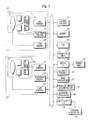
- Fig. 1 is a block diagram illustrating the electrical configuration of a stereoscopic moving-image imaging digital camera.
- the operation of the stereoscopic moving-image imaging digital camera is controlled by a central control unit 31.
- the stereoscopic moving-image imaging digital camera also includes a memory 32, which stores prescribed data, and an automatic control unit 36.
- the stereoscopic moving-image imaging digital camera includes a first imaging unit 10 for capturing a moving image for the right eye, and a second imaging unit 20 for capturing a moving image for the left eye.
- the first imaging unit 10 includes a first image sensing element 13 such as a CCD or C-MOS.
- An imaging lens 11 and a diaphragm 12 are provided in front of the first image sensing element 13.
- the imaging lens 11 is positioned by a lens control unit 16.
- the diaphragm 12 has its aperture controlled by a diaphragm control unit 15.
- a right-eye video signal representing the image of a subject captured by the first image sensing element 13 is input to an ADC (Analog-Digital Converter) control unit 14.
- ADC Analog-Digital Converter
- Prescribed processing such as analog/digital conversion processing is executed in the ADC control unit 14, whereby a conversion is made to moving image data representing the moving image for the right eye.
- the second imaging unit 20 also includes a second image sensing element 23.
- An imaging lens 21 and a diaphragm 22 are provided in front of the second image sensing element 23.
- the imaging lens 21 is positioned by a lens control unit 26.
- the diaphragm 22 has its aperture controlled by a diaphragm control unit 25.
- a left-eye video signal representing the image of a subject captured by the left image sensing element 23 is subjected to prescribed processing such as analog/digital conversion processing in an ADC control unit 24, whereby a conversion is made to moving image data representing the moving image for the right eye.
- an imaging mode When an imaging mode is set in an operation unit 34, the right-eye moving image data that has been output from the ADC control unit 14 and the left-eye moving image data that has been output from the ADC control unit 24 are subjected to prescribed image processing in an image processing unit 37 and then input to a liquid crystal display device 33.
- the captured image of the subject is displayed in the form of a moving image.
- An external display unit 41 can also be connected to the stereoscopic imaging digital camera.
- the stereoscopic imaging camera is provided with an input/output interface 39. By connecting the external display unit 41 to the input/output interface 39, the stereoscopic image (stereoscopic moving image) obtained (reproduced) by imaging is displayed on the display screen of the external display unit 41.
- the right-eye moving image data that has been output from the ADC control unit 14 and the left-eye moving image data that has been output from the ADC control unit 24 are input to a parallax-amount determination unit 38.
- the parallax-amount determination unit 38 determines whether a portion of the image of the subject having parallax equal to or greater than a prescribed threshold value is included in one frame of a stereoscopic image (one set of an image for the left eye and image for the right eye) constituting the stereoscopic moving image.
- a stereoscopic image that includes a portion of the image of the subject having parallax equal to or greater than the prescribed threshold value
- a parallax adjustment is applied to the one set of images for the left eye and right eye, which represents this stereoscopic image, in such a manner that the stereoscopic image will not include the portion of the image of the subject having parallax equal to or greater than the prescribed threshold value.
- the image data for the left eye and the image data for the right eye obtained by imaging are applied to a memory card 40 via a media interface 35 and are recorded on the memory card 40 as stereoscopic image data.
- the parallax-adjusted left-eye image and right-eye image are recorded on the memory card 40 of the left-eye image data and right-eye image data representing the respective left- and right-eye images.
- cross-point information representing a cross point that indicates a location where parallax is not produced is also recorded on the memory card 40 in addition to the moving image data representing the stereoscopic moving image.
- the cross point is predetermined (at a distance of 2 m in front of the stereoscopic imaging digital camera, by way of example). Normally a subject is imaged so as to eliminate parallax at the location decided by the cross point. However, in a case where parallax equal to or greater than the prescribed threshold value occurs, as mentioned above, the parallax adjustment is applied to the left- and right-eye images representing the stereoscopic image of the frame. As a result, the position of the cross point shifts as well.
- cross-point information is recorded on the memory card 40 in correspondence with frames of the stereoscopic image constituting the stereoscopic moving image.
- it may be arranged so that cross-point information is recorded frame by frame only for frames of the stereoscopic image in which a predetermined cross point has shifted, without recording cross-point information frame by frame in correspondence with the frames.
- cross-point information representing the predetermined cross point also is recorded on the memory card 40.
- Fig. 2 illustrates the header of a file (a file containing stereoscopic moving image data) in which cross-point (CP) information has been recorded.
- the cross-point information may just as well be recorded in an image data recording area of the file and not in the header.
- Cross points of first, second and third frames constituting a stereoscopic moving image are at 2 m, 2.1 m and 2.3 m, respectively, and these items of cross-point information have been recorded on the memory card 59.
- Cross-point information has been recorded with regard to other frames as well.
- the stereoscopic imaging digital camera also has a playback function.
- Stereoscopic moving image data representing a stereoscopic moving image recorded on the memory card 40 is read from the memory card 40 via the media interface 35.
- the stereoscopic moving image data that has been read is applied to the liquid crystal display device 33.
- the stereoscopic moving image represented by the stereoscopic moving image data is displayed on the display screen of the liquid crystal display device 33.
- the stereoscopic imaging digital camera can also be connected to the external display unit 41, and the stereoscopic moving image represented by the stereoscopic moving image data that has been recorded on the memory card 40 can also be displayed on the external display unit 41.
- the stereoscopic moving image data that has been read from the memory card 40 is applied to the external display unit 41 via the input/output interface 39.
- the stereoscopic moving image is displayed on the external display unit 41 as a result.
- an image portion representing a subject at a position deeper than the cross point in the stereoscopic image is caused to blur. Since the image portion representing the subject at this deep position is blurred in this manner, the observer can be prevented from closely observing this image portion. Since blurring is not applied to an image portion representing a subject at a position shallower than the cross point in the stereoscopic image, the image is displayed stereoscopically. Since the display screen of the liquid crystal display device 33 provided on the back of the stereoscopic imaging digital camera is comparatively small, there is not a large amount of parallax.
- the blurring processing can utilize a smoothing filter and can also be implemented by software.
- the stereoscopic imaging digital camera is provided with a blurring processing unit 42 in order to execute blurring processing.
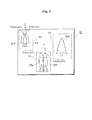
- Fig. 3 is an example of a reproduced stereoscopic image.
- This stereoscopic image 50 is represented by superimposing an image for the left eye and an image for the right eye.
- the left-eye image and right-eye image may be superimposed simultaneously, or it will suffice if the left-eye image and right-eye image can be seen by the observer in essentially superimposed form by displaying them with a temporal shift.
- the stereoscopic image 50 contains a first area 51 at the upper left, a second area 52 at the upper right and a third area 53 in front.
- the second area 52 is an area in which the cross point is located.
- the first area 51 is an area farther (deeper) than the cross point, and the third area 53 is an area nearer (shallower) than the cross point.
- the second area 52 includes an image 52A of a tree. Since the second area 52 is the area having the cross point, the image 52A of the tree is devoid of parallax (this image is not expressed by images offset to the left and right).
- the first area 51 includes tree images 51L and 51R offset to the left and right. One tree image 51L is represented by an image for the left eye, and the other tree image 51R is represented by an image for the right eye. Parallax is produced between the tree images 51L and 51R.
- the third area 53 includes person images 53L and 53R offset to the left and right. One person image 53L is represented by an image for the left eye, and the other person image 53R is represented by an image for the right eye. In this background example, blurring processing is applied to the images 51L and 51R representing a subject farther than the cross point.
- Parallax is utilized in order to find an image portion farther than the cross point in the stereoscopic image.
- Fig. 4 is an example of a stereoscopic image for describing parallax. Items in Fig. 4 identical with those shown in Fig. 3 are designated by like reference characters and a description thereof is omitted.
- Such processing is executed with regard to the entirety of the stereoscopic image 50 and an image portion representing a subject farther (deeper) than the cross point and an image portion representing a subject nearer (shallower) than the cross point are found in the stereoscopic image 50.
- processing may be executed at one pixel or at a plurality of pixels within this area and an image within the area may be judged to be farther than or nearer than the cross point depending upon the result.
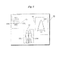
- Fig. 5 is an example of a reproduced stereoscopic image.
- the second area 52 is an area of the cross point
- the first area 51 is an area representing the subject farther than the cross point
- the third area 53 is an area nearer than the cross point. Since the first area 51 is an area representing the subject farther than the cross point, the images 51R and 51L within the area 51 have been caused to blur. As a result, the observer can be prevented from closely observing the images 51R and 51L within the area 51.
- Fig. 6 is a flowchart illustrating a playback processing procedure.
- the stereoscopic imaging digital camera and the external display apparatus (e.g., a television apparatus) 41 are connected and begin communicating (step 61).
- Cross-point information and stereoscopic moving image data are read from the memory card 40 (step 62).
- an image portion farther than the cross point is found and blurring processing is applied to the image portion found (step 63), as described above.
- Stereoscopic images blurred with regard to image portions farther than the cross point are displayed successively on the external display unit 41, whereby a stereoscopic moving image is displayed (step 64).
- the background example described above concerns a stereoscopic moving image
- the invention is not limited to a stereoscopic moving image and similar processing can be applied to a stereoscopic still image as well.
- Figs. 7 to 9 illustrate another background example.
- an image portion representing a subject at a position farther than the cross point is caused to blur.
- the farther an image portion is from the cross point the greater the amount of blurring applied.
- Fig. 7 illustrates an example of a reproduced stereoscopic image. Items in Fig. 7 identical with those shown in Fig. 3 are designated by like reference characters and a description thereof is omitted.
- a stereoscopic image 60 contains a fourth area 54 in addition to the first area 51, second area 52 and third area 53.
- the fourth area 54 includes an image 54L of a tree for the left eye and an image 54R of the tree for the right eye.
- a subject represented by these images 54L and 54R is located at a position farther than the subject represented by the images 51L and 51R included in the first area 51.
- Fig. 8 is an example of a stereoscopic image that has been subjected to blurring processing.
- the tree images 51L and 51R within the first area 51 and the tree images 54L and 54R within the second area 54 which represent subjects farther than the cross point, have all been blurred.
- the subject represented by the tree images 54L and 54R within the second area 54 is farther than the subject represented by the tree images 51L and 51R within the first area 51, the amount of blurring applied to it is greater.
- Fig. 9 which corresponds to Fig. 6 , is a flowchart illustrating a playback processing procedure. Processing in Fig. 9 identical with that shown in Fig. 6 is designated by like reference characters and a description thereof is omitted.
- Cross-point information, stereoscopic moving image data and information representing parallax are read from the memory card 40 (steps 62, 65).
- step 66 it is judged whether blurring processing is that of a first stage (step 66). Whether blurring processing is that of a first stage is decided by a setting made at the operation unit 34. If blurring processing has been set to a first stage by the operation unit 34 ("YES" at step 66), then image portions representing subjects far from the cross point are subjected to uniform blurring processing (step 63) in the manner described above. If blurring processing has not been set to the first stage by the operation unit 34 ("NO" at step 66), then blurring processing is executed in such a manner that the more an image portion represents a subject deeper than the cross point, the more the amount of blurring is increased (step 67).
- Figs. 10 to 12 illustrate an embodiment. This embodiment changes the amount of blurring in accordance with the size of the display screen that displays the stereoscopic image.
- the amount of blurring may just as well be changed in accordance with the display screen size while changing the amount of blurring the deeper an image portion is from the cross point in the manner described above.
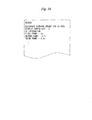
- Fig. 10 illustrates the contents of the header of a file in which the above-mentioned cross-point information has been recorded.
- a reference amount of blurring with respect to a prescribed display screen size has been stored in addition to the above-mentioned cross-point information.
- a reference amount of blurring is represented by D in case of a 42-inch display screen size.
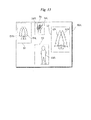
- Figs. 11a and 11b are examples of reproduced stereoscopic images. Items in these figures identical with those shown in Fig. 8 are designated by like reference characters and a description thereof is omitted.
- Fig. 11a is the example of the stereoscopic image 60 displayed on the display screen of a 37-inch
- Fig. 11b is the example of the stereoscopic image 60 displayed on the display screen of a 42-inch.
- the amount of blurring prevailing when a stereoscopic image is displayed on the 42-inch display screen is the blurring amount D, as mentioned above, then the amount of blurring that prevails when the stereoscopic image is displayed on a 37-inch display screen will be (37-inch size / 42-inch size) x D.
- Fig. 12 which corresponds to Fig. 6 , is a flowchart illustrating a playback processing procedure. Processing in Fig. 12 identical with that shown in Fig. 6 is designated by like reference characters and a description thereof is omitted.
- the stereoscopic imaging digital camera and the external display apparatus 41 are connected, size information representing the size of the display screen of external display unit 41 is read from the external display unit 41 and a reference blurring amount that has been recorded on the memory card 40 is read (step 68).
- a cross point that matches the size of the display screen represented by the read size information is calculated.
- the image for the left eye and the image for the right eye are adjusted in such a manner that the parallax at the calculated cross point vanishes.
- a blurring amount matching the display screen that displays the stereoscopic image is calculated from the read reference blurring amount.
- a subject located at a position farther than the calculated cross point is caused to blur at the blurring amount calculated from the reference blurring amount (step 69).
- a cross point is calculated in accordance with the size of the display screen and images for the left and right eyes are adjusted in such a manner that the parallax at the calculated cross point vanishes. Also, so that a blurring amount conforming to the size of the display screen is applied based upon the read reference blurring amount without calculating a cross point conforming to the display screen and without adjusting the images for the left and right eyes.
- Figs. 13 and 14 illustrate another embodiment. This embodiment changes the cross point at the time of playback.
- Fig. 13 is an example of a stereoscopic image displayed on a display screen.
- a stereoscopic image 60A contains the first area 51, second area 52, third area 53 and fourth area 54 in a manner similar to the stereoscopic image 60 shown in Fig. 8 .
- the second area 52 contains the cross point and the tree image 52A devoid of parallax is being displayed.
- the cross point has been moved to the third area 53 that represents a subject shallower than the subject represented by the image portion contained in the second area 52.
- the tree images 52L and 52R within the second area 52 become overlapping images and the person image 53A within the third area 53 becomes an image devoid of parallax.
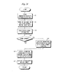
- Fig. 14 is a flowchart illustrating a playback processing procedure.
- the stereoscopic imaging digital camera and the external display apparatus 41 are connected and begin communicating (step 61).
- Stereoscopic moving image data that has been recorded on the memory card 40 is read (step 71).
- cross-point information and reference blurring amount with respect to display screen size for every stereoscopic image constituting the stereoscopic moving image are read from the header of the file containing the stereoscopic moving image data (step 72).
- parallax information for every stereoscopic image also is read from the file (step 73). It goes without saying that the parallax information is generated at the time of recording of the stereoscopic moving image data and that it has been stored in the file header along with the cross-point information and reference blurring amount. Naturally, it may be arranged so that the parallax information is generated at the time of playback without being recorded beforehand.
- parallax is outside the allowed range if the parallax is equal to or greater than a prescribed threshold value, and that parallax is within the allowed range if the parallax is less than the prescribed threshold value.
- parallax is not within the allowed range ("NO" at step 74)
- the cross point is moved toward the short-distance side (shallower) (step 75).
- Parallax of an image portion representing a shallow subject vanishes, as illustrated in Fig. 13 .
- the image portion representing a subject farther than the cross point at the time of recording is caused to blur in accordance with amount of parallax and the display screen size of the external display unit (step 76).
- the image portion representing the subject farther than this cross point is caused to blur in accordance with the amount of parallax and display screen size of the external display unit (step 76).
- step 77 If processing regarding the stereoscopic images of all frames that constitute the stereoscopic image is not finished ("NO" at step 77), then the stereoscopic imaging digital camera is controlled in such a manner that similar processing is applied to the stereoscopic image of the next frame (step 78), and the processing of steps 74 to 76 is repeated.
- the stereoscopic moving image is displayed (step 64).
- Figs. 15 to 21 illustrate another embodiment. This embodiment arranges it so that in a case where the scene of a stereoscopic moving image changes, the observer will not be given an impression of a sudden change in scene.
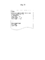
- Fig. 15 illustrates the contents of a header.
- a scene-change frame representing a frame in which the scene changes over has been recorded in the header in addition to the cross-point information.
- a 134 th frame is a scene-change frame and there is a changeover between the scene of the stereoscopic moving image extending up to the 133 rd frame and the scene of the stereoscopic moving image from the 134 th frame onward.
- Fig. 16 is a time chart representing scenes of a stereoscopic moving image.
- Frames from the first frame to the 133 rd frame constitute the stereoscopic moving image of a scene A, and frames from the 134 th frame onward constitute the stereoscopic moving image of a scene B.
- Fig. 17 is a time chart illustrating the timing at which stereoscopic images before and after the scene changeover of the stereoscopic moving image are caused to blur in their entirety.
- stereoscopic images are displayed upon being blurred in their entirety over a total of two seconds, namely one second before and one second after the scene-change frame. Since the stereoscopic images before and after the scene change are blurred entirely, the observer is not imparted with a sense of oddness even though the scene changes.
- Fig. 18 illustrates an example of stereoscopic images.
- Fig. 19 which illustrates a modification, is a time chart illustrating the timing at which stereoscopic images before and after a scene changeover of a stereoscopic moving image are caused to blur in their entirety.
- stereoscopic images are caused to blur entirely before and after the scene changes over.
- stereoscopic images of a plurality of frames preceding the changeover of the scene are displayed in gradually decreasing size, and stereoscopic images of a plurality of frames following the scene changeover gradually increase in size and take on the original size of the stereoscopic image.
- Fig. 20 illustrates the manner in which the size of stereoscopic images changes before and after a scene changes over.
- stereoscopic images of a plurality of frames preceding the changeover of the scene gradually decrease in size from an original size 60B of the stereoscopic image, and the image of the frame immediately preceding the scene changeover or of the frame in which the scene changes over takes on the smallest size 60C. After the scene changes over, the sizes of the images gradually increase and take on the size 60B of the original stereoscopic image.
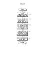
- Fig. 21 which corresponds to Fig. 6 , is a flowchart illustrating a playback processing procedure. Processing in Fig. 21 identical with that shown in Fig. 6 is designated by like reference characters and a description thereof is omitted.
- Step 101 Scene-change information that has been recorded on the memory card 40 is read (step 101).
- processing such as processing for blurring in their entirety stereoscopic images before and after the scene changeover and for reducing and enlarging stereoscopic images, as described above, is executed (step 104). Thereafter, processing for blurring an image portion representing a subject farther than the cross point is executed (step 69), as described above. If there is no scene changeover ("NO" at step 102), then step 104 is skipped.
- the processing shown in Fig. 6 , the processing shown in Fig. 9 , the processing shown in Fig. 12 , the processing shown in Fig. 14 and the processing shown in Fig. 21 appear in the drawings as processes that are separate from one another. However, any number of these processes may be combined. For example, from among the processing shown in Fig. 9 , the processing shown in Fig. 12 , the processing shown in Fig. 14 and the processing shown in Fig. 21 , one or any number of the processes may be combined with the processing shown in Fig. 6 ; from among the processing shown in Fig. 12 , the processing shown in Fig. 14 and the processing shown in Fig.
- one or any number of the processes may be combined with the processing shown in Fig. 9 ; either or both of the processing shown in Figs. 14 and 21 may be combined with the processing shown in Fig. 12 ; and the processing shown in Fig. 14 and the processing shown in Fig. 21 may be combined.
- a stereoscopic image is caused to blur in such a manner that the deeper an image portion relative to a cross point, the larger the amount of blurring becomes.
- it may be arranged so that the shallower an image portion relative to a cross point, the more the stereoscopic image is caused to blur.
- the processing for blurring a stereoscopic image more the shallower an image portion is relative to the cross point may just as well be executed in the above-mentioned processing shown in Fig. 9 , processing shown in Fig. 12 , processing shown in Fig. 14 or processing shown in Fig. 21 , or it may be executed in any combination of these. It goes without saying that such blurring processing can be implemented using a smoothing filter.
Description
- This invention relates to a stereoscopic image display control apparatus and to a method of controlling the operation of this apparatus.
- By displaying on a display screen a left-eye image (an image observed by the left eye of the observer) and a right-eye image (an image observed by the right eye of the observer) having parallax, an image can be viewed stereoscopically. There are occasions where the user may find viewing unconformable if there is too much parallax. For this reason, there is a technique for applying blurring processing to areas where parallax separation is great (Japanese Patent Application Laid-Open No.
4-343685 JP-H06-194602 9-43468 JP-H10-239634 - However, with the technique of merely blurring areas where parallax separation is great, there are instances where the image cannot be enjoyed as a stereoscopic image and viewing becomes uncomfortable.
-
WO-A1-2009/149413 discloses a method and apparatus for selectively blurring parts of an image set according to differences in disparity between successive images. As a result, the one-dimensional 'ringing' edge artifacts, intrinsic to autostereoscopic displays, are hidden, thereby improving the perceived image quality of a multi-view autostereoscopic image. The method may involve detecting regions of disparity between adjacent views, and then blurring those regions by weighted local pixel averaging. The relationship between the blur radius and the disparity is preferentially non-linear to maintain sharpness of low disparity regions. -
US-A1-2007/0236560 discloses three general designs for reducing parallax in a moving picture. One design comprises stretching graphics content near the left and right frame edges of stereo pair elements in order to modify parallax settings. A second design comprises identifying a plurality of substantially corresponding points in a left eye view and right eye view and bringing the plurality of substantially corresponding points closer together using a morph technique. The third design entails fading a portion of a right eye view with a portion of a left eye view near or proximate an edge of the image. -
WO-A1-2004/084550 discloses a stereoscopic video photographing/displaying system comprising a stereoscopic video imaging unit having two imaging means and outputting video information therefrom, a stereoscopic video display for displaying different videos on both eyes of a viewer, and a medium for transmitting image information from the stereoscopic video imaging unit to the stereoscopic video display, the stereoscopic video imaging unit comprising means for measuring cross point information concerning the cross point (CP) of the optical axes of the imaging means, characterized in that an offset setting means for delivering information including the CP information and the video information to the medium and displaying the different videos while shifting based on the video information, the cross point information, and the size information of an image being displayed by the stereoscopic video display. -
EP-A2-2106150 discloses a method, apparatus and program for stereoscopic videos. Fatigue in users who stereoscopically view stereoscopic videos is reduced during switching among scenes in stereoscopic videos. A video input section receives input of stereoscopic videos constituted by a plurality of frames, which are viewable stereoscopically. A scene detecting section detects positions within the stereoscopic videos at which scene changes occur. A perceived depth adjusting section administers perceived depth adjusting processes that adjust the perceived depths of the stereoscopic videos such that the perceived depth changes gradually at the positions at which scene changes occur, to obtain processed stereoscopic videos. -
WO-A1-2010/046824 discloses a system and method of processing an input three dimensional video signal comprising multiple views, the method comprising: determining a far disparity estimate indicative of the largest disparity value for the input three dimensional video signal, a near disparity estimate indicative of the smallest disparity value for a spatial region within the input three dimensional video signal, adapting the input three dimensional video signal by shifting the input three dimensional video signal backwards by means of a disparity shift based on the far disparity estimate and generating an overlay within the spatial region for the shifted three dimensional video signal based on the near disparity estimate and the disparity shift. - An object of the present invention is to display a stereoscopic image that is devoid of viewing discomfort.
- The present invention provides a stereoscopic image display control apparatus according to
Claim 1. - The present invention also provides a method of controlling operation of a stereoscopic image display control apparatus according to
Claim 5. -
-
Fig. 1 is a block diagram illustrating the electrical configuration of a stereoscopic imaging digital camera; -
Fig. 2 illustrates the contents of a header; -
Fig. 3 is an example of a stereoscopic image; -
Fig. 4 is an example of a stereoscopic image; -
Fig. 5 is an example of a stereoscopic image; -
Fig. 6 is a flowchart illustrating a playback processing procedure; -
Fig. 7 is an example of a stereoscopic image; -
Fig. 8 is an example of a stereoscopic image; -
Fig. 9 is a flowchart illustrating a playback processing procedure; -
Fig. 10 illustrates the contents of a header; -
Figs. 11a and 11b are examples of stereoscopic images; -
Fig. 12 is a flowchart illustrating a playback processing procedure; -
Fig. 13 is an example of a stereoscopic image; -
Fig. 14 is a flowchart illustrating a playback processing procedure; -
Fig. 15 illustrates the contents of a header; -
Fig. 16 illustrates the manner in which a scene changes; -
Fig. 17 illustrates the manner in which a scene changes over; -
Fig. 18 illustrates how stereoscopic images appear when a scene changes over; -
Fig. 19 illustrates the manner in which a scene changes over; -
Fig. 20 illustrates the manner in which the size of stereoscopic images changes when a scene changes over; and -
Fig. 21 is a flowchart illustrating a playback processing procedure. - The following describes that stereoscopic image data and cross-point information have been recorded on a recording medium. The stereoscopic image data and cross-point information are read from the recording medium and an image portion in the stereoscopic image representing a subject at a position deeper than the cross point, which is represented by the cross-point information, is caused to blur in such a manner that the deeper into the stereoscopic image from the cross point, the more the amount of blurring applied. The stereoscopic image thus blurred is displayed. If an image portion representing a subject shallower that the cross point is caused to blur, there are instances where the resulting image cannot be enjoyed as a stereoscopic image. However, an image portion representing a subject shallower that the cross point is not caused to blur. Even if blurring processing is applied, therefore, the resulting image can be enjoyed as a stereoscopic image. Furthermore, although the deeper into the stereoscopic image from the cross point, the greater the amount of parallax becomes, the adverse effect of this parallax upon the observer can be mitigated because the amount of blurring also increases the greater the distance inward from the cross point.
- By way of example, the first blurring unit blurs an image portion, which represents a subject at a position deeper than the cross point detected by the cross point detection unit in the stereoscopic image, in such a manner that the larger a display screen of the display device, the more the amount of blurring becomes.
-
Fig. 1 is a block diagram illustrating the electrical configuration of a stereoscopic moving-image imaging digital camera. - The operation of the stereoscopic moving-image imaging digital camera is controlled by a
central control unit 31. The stereoscopic moving-image imaging digital camera also includes amemory 32, which stores prescribed data, and anautomatic control unit 36. - The stereoscopic moving-image imaging digital camera includes a
first imaging unit 10 for capturing a moving image for the right eye, and asecond imaging unit 20 for capturing a moving image for the left eye. - The
first imaging unit 10 includes a firstimage sensing element 13 such as a CCD or C-MOS. Animaging lens 11 and adiaphragm 12 are provided in front of the firstimage sensing element 13. Theimaging lens 11 is positioned by alens control unit 16. Thediaphragm 12 has its aperture controlled by adiaphragm control unit 15. A right-eye video signal representing the image of a subject captured by the firstimage sensing element 13 is input to an ADC (Analog-Digital Converter)control unit 14. Prescribed processing such as analog/digital conversion processing is executed in theADC control unit 14, whereby a conversion is made to moving image data representing the moving image for the right eye. - The
second imaging unit 20 also includes a secondimage sensing element 23. Animaging lens 21 and adiaphragm 22 are provided in front of the secondimage sensing element 23. Theimaging lens 21 is positioned by alens control unit 26. Thediaphragm 22 has its aperture controlled by adiaphragm control unit 25. A left-eye video signal representing the image of a subject captured by the leftimage sensing element 23 is subjected to prescribed processing such as analog/digital conversion processing in anADC control unit 24, whereby a conversion is made to moving image data representing the moving image for the right eye. - When an imaging mode is set in an
operation unit 34, the right-eye moving image data that has been output from theADC control unit 14 and the left-eye moving image data that has been output from theADC control unit 24 are subjected to prescribed image processing in animage processing unit 37 and then input to a liquidcrystal display device 33. The captured image of the subject is displayed in the form of a moving image. Anexternal display unit 41 can also be connected to the stereoscopic imaging digital camera. In order to connect theexternal display unit 41 to the stereoscopic imaging digital camera, the stereoscopic imaging camera is provided with an input/output interface 39. By connecting theexternal display unit 41 to the input/output interface 39, the stereoscopic image (stereoscopic moving image) obtained (reproduced) by imaging is displayed on the display screen of theexternal display unit 41. - When a recording mode is set in the
operation unit 34, the right-eye moving image data that has been output from theADC control unit 14 and the left-eye moving image data that has been output from theADC control unit 24 are input to a parallax-amount determination unit 38. - The parallax-
amount determination unit 38 determines whether a portion of the image of the subject having parallax equal to or greater than a prescribed threshold value is included in one frame of a stereoscopic image (one set of an image for the left eye and image for the right eye) constituting the stereoscopic moving image. With regard to a stereoscopic image that includes a portion of the image of the subject having parallax equal to or greater than the prescribed threshold value, a parallax adjustment is applied to the one set of images for the left eye and right eye, which represents this stereoscopic image, in such a manner that the stereoscopic image will not include the portion of the image of the subject having parallax equal to or greater than the prescribed threshold value. - The image data for the left eye and the image data for the right eye obtained by imaging are applied to a
memory card 40 via amedia interface 35 and are recorded on thememory card 40 as stereoscopic image data. In a case where the parallax adjustment has been applied, it goes without saying that the parallax-adjusted left-eye image and right-eye image are recorded on thememory card 40 of the left-eye image data and right-eye image data representing the respective left- and right-eye images. By recording the left-eye image data and right-eye image data on thememory card 40 frame by frame, moving image data (moving image data for the left eye and moving image data for the right eye) representing a stereoscopic moving image is recorded on thememory card 40. - In this background example, cross-point information representing a cross point that indicates a location where parallax is not produced is also recorded on the
memory card 40 in addition to the moving image data representing the stereoscopic moving image. In this background example, the cross point is predetermined (at a distance of 2 m in front of the stereoscopic imaging digital camera, by way of example). Normally a subject is imaged so as to eliminate parallax at the location decided by the cross point. However, in a case where parallax equal to or greater than the prescribed threshold value occurs, as mentioned above, the parallax adjustment is applied to the left- and right-eye images representing the stereoscopic image of the frame. As a result, the position of the cross point shifts as well. In this background example, cross-point information is recorded on thememory card 40 in correspondence with frames of the stereoscopic image constituting the stereoscopic moving image. Naturally, it may be arranged so that cross-point information is recorded frame by frame only for frames of the stereoscopic image in which a predetermined cross point has shifted, without recording cross-point information frame by frame in correspondence with the frames. In this case, it goes without saying that cross-point information representing the predetermined cross point also is recorded on thememory card 40. -
Fig. 2 illustrates the header of a file (a file containing stereoscopic moving image data) in which cross-point (CP) information has been recorded. The cross-point information may just as well be recorded in an image data recording area of the file and not in the header. - Cross points of first, second and third frames constituting a stereoscopic moving image are at 2 m, 2.1 m and 2.3 m, respectively, and these items of cross-point information have been recorded on the memory card 59. Cross-point information has been recorded with regard to other frames as well.
- With reference again to
Fig. 1 , the stereoscopic imaging digital camera also has a playback function. Stereoscopic moving image data representing a stereoscopic moving image recorded on thememory card 40 is read from thememory card 40 via themedia interface 35. The stereoscopic moving image data that has been read is applied to the liquidcrystal display device 33. The stereoscopic moving image represented by the stereoscopic moving image data is displayed on the display screen of the liquidcrystal display device 33. As mentioned above, the stereoscopic imaging digital camera can also be connected to theexternal display unit 41, and the stereoscopic moving image represented by the stereoscopic moving image data that has been recorded on thememory card 40 can also be displayed on theexternal display unit 41. In this case, the stereoscopic moving image data that has been read from thememory card 40 is applied to theexternal display unit 41 via the input/output interface 39. The stereoscopic moving image is displayed on theexternal display unit 41 as a result. - If there is inclusion of a portion exhibiting large parallax, there will be instances where the observer viewing the stereoscopic image will find viewing uncomfortable. In accordance with this background example, an image portion representing a subject at a position deeper than the cross point in the stereoscopic image is caused to blur. Since the image portion representing the subject at this deep position is blurred in this manner, the observer can be prevented from closely observing this image portion. Since blurring is not applied to an image portion representing a subject at a position shallower than the cross point in the stereoscopic image, the image is displayed stereoscopically. Since the display screen of the liquid
crystal display device 33 provided on the back of the stereoscopic imaging digital camera is comparatively small, there is not a large amount of parallax. However, since the display screen of theexternal display unit 41 is comparatively large, the amount of parallax also is greater and the observer may find viewing uncomfortable. This background example is effective in a case where a stereoscopic image is displayed on a comparatively large display screen such as that of theexternal display unit 41. The blurring processing can utilize a smoothing filter and can also be implemented by software. The stereoscopic imaging digital camera is provided with ablurring processing unit 42 in order to execute blurring processing. -
Fig. 3 is an example of a reproduced stereoscopic image. - This
stereoscopic image 50 is represented by superimposing an image for the left eye and an image for the right eye. The left-eye image and right-eye image may be superimposed simultaneously, or it will suffice if the left-eye image and right-eye image can be seen by the observer in essentially superimposed form by displaying them with a temporal shift. - The
stereoscopic image 50 contains afirst area 51 at the upper left, asecond area 52 at the upper right and athird area 53 in front. Thesecond area 52 is an area in which the cross point is located. Thefirst area 51 is an area farther (deeper) than the cross point, and thethird area 53 is an area nearer (shallower) than the cross point. - The
second area 52 includes animage 52A of a tree. Since thesecond area 52 is the area having the cross point, theimage 52A of the tree is devoid of parallax (this image is not expressed by images offset to the left and right). Thefirst area 51 includestree images tree image 51L is represented by an image for the left eye, and theother tree image 51R is represented by an image for the right eye. Parallax is produced between thetree images third area 53 includesperson images person image 53L is represented by an image for the left eye, and theother person image 53R is represented by an image for the right eye. In this background example, blurring processing is applied to theimages - Parallax is utilized in order to find an image portion farther than the cross point in the stereoscopic image.
-
Fig. 4 is an example of a stereoscopic image for describing parallax. Items inFig. 4 identical with those shown inFig. 3 are designated by like reference characters and a description thereof is omitted. - Consider the image for the left eye as a reference. It is also permissible to consider the image for the right eye as the reference. Consider a specific pixel P1 in the
tree image 51L contained in thefirst area 51. A pixel P2 corresponding to the pixel P1 is found in theother tree image 51R. If we let (xL1, yL1) be the position of the pixel P1 and let (xR1, yR1) be the position of the pixel P2, then parallax d1 will be d1 = (xL1 - xR1). Parallax d1 is positive. Since parallax d1 is positive, it is judged that the subject represented by pixels P1, P2 is farther than the cross point. Similarly, consider a specific pixel P3 in theperson image 53L contained in thethird area 53. A pixel P4 corresponding to the pixel P2 is found in theother person image 53R. If we let (xL2, yL2) be the position of the pixel P3 and let (xR2, yR2) be the position of the pixel P4, then parallax d2 will be d2 = (xL2 - xR2). Parallax d2 is negative. Since parallax d2 is negative, it is judged that the subject represented by pixels P3, P4 is nearer than the cross point. Such processing is executed with regard to the entirety of thestereoscopic image 50 and an image portion representing a subject farther (deeper) than the cross point and an image portion representing a subject nearer (shallower) than the cross point are found in thestereoscopic image 50. Naturally, within an area considered to be that of the same subject-image portion, such processing may be executed at one pixel or at a plurality of pixels within this area and an image within the area may be judged to be farther than or nearer than the cross point depending upon the result. -
Fig. 5 is an example of a reproduced stereoscopic image. - As mentioned above, the
second area 52 is an area of the cross point, thefirst area 51 is an area representing the subject farther than the cross point, and thethird area 53 is an area nearer than the cross point. Since thefirst area 51 is an area representing the subject farther than the cross point, theimages area 51 have been caused to blur. As a result, the observer can be prevented from closely observing theimages area 51. -
Fig. 6 is a flowchart illustrating a playback processing procedure. - The stereoscopic imaging digital camera and the external display apparatus (e.g., a television apparatus) 41 are connected and begin communicating (step 61). Cross-point information and stereoscopic moving image data are read from the memory card 40 (step 62). With regard to each frame of a stereoscopic image that constitutes the stereoscopic moving image represented by the stereoscopic moving image data, an image portion farther than the cross point is found and blurring processing is applied to the image portion found (step 63), as described above. Stereoscopic images blurred with regard to image portions farther than the cross point are displayed successively on the
external display unit 41, whereby a stereoscopic moving image is displayed (step 64). - Although the background example described above concerns a stereoscopic moving image, it goes without saying that the invention is not limited to a stereoscopic moving image and similar processing can be applied to a stereoscopic still image as well.
-
Figs. 7 to 9 illustrate another background example. In the background example set forth above, an image portion representing a subject at a position farther than the cross point is caused to blur. In this background example, the farther an image portion is from the cross point, the greater the amount of blurring applied. -
Fig. 7 illustrates an example of a reproduced stereoscopic image. Items inFig. 7 identical with those shown inFig. 3 are designated by like reference characters and a description thereof is omitted. - A
stereoscopic image 60 contains afourth area 54 in addition to thefirst area 51,second area 52 andthird area 53. Thefourth area 54 includes animage 54L of a tree for the left eye and animage 54R of the tree for the right eye. A subject represented by theseimages images first area 51. -
Fig. 8 is an example of a stereoscopic image that has been subjected to blurring processing. - As mentioned above, the
tree images first area 51 and thetree images second area 54, which represent subjects farther than the cross point, have all been blurred. However, since the subject represented by thetree images second area 54 is farther than the subject represented by thetree images first area 51, the amount of blurring applied to it is greater. - Although the deeper into the stereoscopic image from the cross point, the greater the parallax, the deeper into the stereoscopic image, the greater the amount of blurring applied. Thus it can be arranged so that an image portion exhibiting large parallax will not be observed closely.
-
Fig. 9 , which corresponds toFig. 6 , is a flowchart illustrating a playback processing procedure. Processing inFig. 9 identical with that shown inFig. 6 is designated by like reference characters and a description thereof is omitted. - In this background example, it is assumed that information representing the parallax of images has been generated in advance and that this information representing parallax has been recorded on the
memory card 40 in correspondence with each frame of a stereoscopic image that constitutes a stereoscopic moving image, as described above. It goes without saying that it may be arranged so that parallax is calculated at the time of playback without information representing parallax having been recorded on thememory card 40 beforehand. - Cross-point information, stereoscopic moving image data and information representing parallax are read from the memory card 40 (
steps 62, 65). - Next, it is judged whether blurring processing is that of a first stage (step 66). Whether blurring processing is that of a first stage is decided by a setting made at the
operation unit 34. If blurring processing has been set to a first stage by the operation unit 34 ("YES" at step 66), then image portions representing subjects far from the cross point are subjected to uniform blurring processing (step 63) in the manner described above. If blurring processing has not been set to the first stage by the operation unit 34 ("NO" at step 66), then blurring processing is executed in such a manner that the more an image portion represents a subject deeper than the cross point, the more the amount of blurring is increased (step 67). -
Figs. 10 to 12 illustrate an embodiment. This embodiment changes the amount of blurring in accordance with the size of the display screen that displays the stereoscopic image. The amount of blurring may just as well be changed in accordance with the display screen size while changing the amount of blurring the deeper an image portion is from the cross point in the manner described above. -
Fig. 10 illustrates the contents of the header of a file in which the above-mentioned cross-point information has been recorded. - In this embodiment, a reference amount of blurring with respect to a prescribed display screen size has been stored in addition to the above-mentioned cross-point information. For example, a reference amount of blurring is represented by D in case of a 42-inch display screen size.
-
Figs. 11a and 11b are examples of reproduced stereoscopic images. Items in these figures identical with those shown inFig. 8 are designated by like reference characters and a description thereof is omitted. -
Fig. 11a is the example of thestereoscopic image 60 displayed on the display screen of a 37-inch, andFig. 11b is the example of thestereoscopic image 60 displayed on the display screen of a 42-inch. - The larger the image displayed, the greater parallax becomes. For example, in
Fig. 11a , assume that the parallax between theimages first area 51 is d37, and inFig. 11b , assume that the parallax between theimages first area 51 is d42. In such case, d42 > d37 holds. In this embodiment, the larger the display screen size and the greater the parallax, the more the amount of blurring becomes, and the smaller the display screen size and the smaller the parallax, the smaller the amount of blurring becomes. For example, if we assume that the amount of blurring prevailing when a stereoscopic image is displayed on the 42-inch display screen is the blurring amount D, as mentioned above, then the amount of blurring that prevails when the stereoscopic image is displayed on a 37-inch display screen will be (37-inch size / 42-inch size) x D. -
Fig. 12 , which corresponds toFig. 6 , is a flowchart illustrating a playback processing procedure. Processing inFig. 12 identical with that shown inFig. 6 is designated by like reference characters and a description thereof is omitted. - The stereoscopic imaging digital camera and the
external display apparatus 41 are connected, size information representing the size of the display screen ofexternal display unit 41 is read from theexternal display unit 41 and a reference blurring amount that has been recorded on thememory card 40 is read (step 68). A cross point that matches the size of the display screen represented by the read size information is calculated. The image for the left eye and the image for the right eye are adjusted in such a manner that the parallax at the calculated cross point vanishes. Further, a blurring amount matching the display screen that displays the stereoscopic image is calculated from the read reference blurring amount. A subject located at a position farther than the calculated cross point is caused to blur at the blurring amount calculated from the reference blurring amount (step 69). - In the embodiment described above, a cross point is calculated in accordance with the size of the display screen and images for the left and right eyes are adjusted in such a manner that the parallax at the calculated cross point vanishes. Also, so that a blurring amount conforming to the size of the display screen is applied based upon the read reference blurring amount without calculating a cross point conforming to the display screen and without adjusting the images for the left and right eyes.
-
Figs. 13 and14 illustrate another embodiment. This embodiment changes the cross point at the time of playback. -
Fig. 13 is an example of a stereoscopic image displayed on a display screen. - A
stereoscopic image 60A contains thefirst area 51,second area 52,third area 53 andfourth area 54 in a manner similar to thestereoscopic image 60 shown inFig. 8 . With thestereoscopic image 60 shown inFig. 8 , thesecond area 52 contains the cross point and thetree image 52A devoid of parallax is being displayed. By contrast, with thestereoscopic image 60A shown inFig. 13 , the cross point has been moved to thethird area 53 that represents a subject shallower than the subject represented by the image portion contained in thesecond area 52. As a consequence, thetree images second area 52 become overlapping images and theperson image 53A within thethird area 53 becomes an image devoid of parallax. - Although an image portion shallower than the cross point requires parallax in order to form a stereoscopic image, there are instances where viewing will become uncomfortable for the observer if there is too much parallax. For this reason, in a case where the parallax of an image portion shallower than the cross point of the stereoscopic image at the time of recording is equal to or greater than a prescribed threshold value, the cross point is moved shallower.
-
Fig. 14 is a flowchart illustrating a playback processing procedure. - The stereoscopic imaging digital camera and the
external display apparatus 41 are connected and begin communicating (step 61). Stereoscopic moving image data that has been recorded on thememory card 40 is read (step 71). Further, cross-point information and reference blurring amount with respect to display screen size for every stereoscopic image constituting the stereoscopic moving image are read from the header of the file containing the stereoscopic moving image data (step 72). Furthermore, parallax information for every stereoscopic image also is read from the file (step 73). It goes without saying that the parallax information is generated at the time of recording of the stereoscopic moving image data and that it has been stored in the file header along with the cross-point information and reference blurring amount. Naturally, it may be arranged so that the parallax information is generated at the time of playback without being recorded beforehand. - It is determined whether the parallax of an image portion shallower than (a short distance from) the cross point at the time of recording of the stereoscopic image is within an allowed range (step 74). It is construed that parallax is outside the allowed range if the parallax is equal to or greater than a prescribed threshold value, and that parallax is within the allowed range if the parallax is less than the prescribed threshold value.
- If parallax is not within the allowed range ("NO" at step 74), then the cross point is moved toward the short-distance side (shallower) (step 75). Parallax of an image portion representing a shallow subject vanishes, as illustrated in
Fig. 13 . - If parallax is within the allowed range ("YES" at step 74), then the image portion representing a subject farther than the cross point at the time of recording is caused to blur in accordance with amount of parallax and the display screen size of the external display unit (step 76). The more parallax a portion has, the more the amount of blurring is increased, and the larger the size of the display screen, the more the amount of blurring is increased.
- In a case where the cross point is moved shallower, the image portion representing the subject farther than this cross point is caused to blur in accordance with the amount of parallax and display screen size of the external display unit (step 76).
- If processing regarding the stereoscopic images of all frames that constitute the stereoscopic image is not finished ("NO" at step 77), then the stereoscopic imaging digital camera is controlled in such a manner that similar processing is applied to the stereoscopic image of the next frame (step 78), and the processing of
steps 74 to 76 is repeated. - When processing regarding the stereoscopic images of all frames that constitute the stereoscopic image ends ("YES" at step 77), the stereoscopic moving image is displayed (step 64).
-
Figs. 15 to 21 illustrate another embodiment. This embodiment arranges it so that in a case where the scene of a stereoscopic moving image changes, the observer will not be given an impression of a sudden change in scene. -
Fig. 15 illustrates the contents of a header. - In this embodiment, a scene-change frame representing a frame in which the scene changes over has been recorded in the header in addition to the cross-point information. For example, a 134th frame is a scene-change frame and there is a changeover between the scene of the stereoscopic moving image extending up to the 133rd frame and the scene of the stereoscopic moving image from the 134th frame onward.
-
Fig. 16 is a time chart representing scenes of a stereoscopic moving image. - Frames from the first frame to the 133rd frame constitute the stereoscopic moving image of a scene A, and frames from the 134th frame onward constitute the stereoscopic moving image of a scene B.
-
Fig. 17 is a time chart illustrating the timing at which stereoscopic images before and after the scene changeover of the stereoscopic moving image are caused to blur in their entirety. - As indicated by the hatching, stereoscopic images are displayed upon being blurred in their entirety over a total of two seconds, namely one second before and one second after the scene-change frame. Since the stereoscopic images before and after the scene change are blurred entirely, the observer is not imparted with a sense of oddness even though the scene changes.
-
Fig. 18 illustrates an example of stereoscopic images. - The scene changes when
stereoscopic image 60 of the 133rd frame changes over tostereoscopic image 60A of the 134th frame. Since stereoscopic images before and after a scene changes over are caused to blur entirely, as mentioned above, the observer is not imparted with a sense of oddness even though the scene changes. -
Fig. 19 , which illustrates a modification, is a time chart illustrating the timing at which stereoscopic images before and after a scene changeover of a stereoscopic moving image are caused to blur in their entirety. - In the foregoing embodiment, stereoscopic images are caused to blur entirely before and after the scene changes over. In this embodiment, however, stereoscopic images of a plurality of frames preceding the changeover of the scene are displayed in gradually decreasing size, and stereoscopic images of a plurality of frames following the scene changeover gradually increase in size and take on the original size of the stereoscopic image.
-
Fig. 20 illustrates the manner in which the size of stereoscopic images changes before and after a scene changes over. - As mentioned above, stereoscopic images of a plurality of frames preceding the changeover of the scene gradually decrease in size from an
original size 60B of the stereoscopic image, and the image of the frame immediately preceding the scene changeover or of the frame in which the scene changes over takes on thesmallest size 60C. After the scene changes over, the sizes of the images gradually increase and take on thesize 60B of the original stereoscopic image. -
Fig. 21 , which corresponds toFig. 6 , is a flowchart illustrating a playback processing procedure. Processing inFig. 21 identical with that shown inFig. 6 is designated by like reference characters and a description thereof is omitted. - Scene-change information that has been recorded on the
memory card 40 is read (step 101). When a scene changes over ("YES" at step 102), processing such as processing for blurring in their entirety stereoscopic images before and after the scene changeover and for reducing and enlarging stereoscopic images, as described above, is executed (step 104). Thereafter, processing for blurring an image portion representing a subject farther than the cross point is executed (step 69), as described above. If there is no scene changeover ("NO" at step 102), then step 104 is skipped. - In the foregoing embodiments and background examples, the processing shown in
Fig. 6 , the processing shown inFig. 9 , the processing shown inFig. 12 , the processing shown inFig. 14 and the processing shown inFig. 21 appear in the drawings as processes that are separate from one another. However, any number of these processes may be combined. For example, from among the processing shown inFig. 9 , the processing shown inFig. 12 , the processing shown inFig. 14 and the processing shown inFig. 21 , one or any number of the processes may be combined with the processing shown inFig. 6 ; from among the processing shown inFig. 12 , the processing shown inFig. 14 and the processing shown inFig. 21 , one or any number of the processes may be combined with the processing shown inFig. 9 ; either or both of the processing shown inFigs. 14 and21 may be combined with the processing shown inFig. 12 ; and the processing shown inFig. 14 and the processing shown inFig. 21 may be combined. - Furthermore, in the foregoing embodiments and background examples, a stereoscopic image is caused to blur in such a manner that the deeper an image portion relative to a cross point, the larger the amount of blurring becomes. However, it may be arranged so that the shallower an image portion relative to a cross point, the more the stereoscopic image is caused to blur. Thus, the processing for blurring a stereoscopic image more the shallower an image portion is relative to the cross point may just as well be executed in the above-mentioned processing shown in
Fig. 9 , processing shown inFig. 12 , processing shown inFig. 14 or processing shown inFig. 21 , or it may be executed in any combination of these. It goes without saying that such blurring processing can be implemented using a smoothing filter.
Claims (5)
- A stereoscopic image display control apparatus comprising:a stereoscopic image data reading unit (35) for reading stereoscopic image data that represents a stereoscopic image and that has been recorded on a recording medium (40);a cross-point information reading unit for reading cross-point information that has been recorded on the recording medium and that represents a cross point, the cross point indicating a depth at which no parallax is produced in the stereoscopic image;a parallax determination unit (38) for determining whether a parallax of a first image portion representing a subject at a depth shallower than the cross point in the stereoscopic image is equal to or greater than a threshold value;characterized bya cross-point control unit for controlling the stereoscopic image data, wherein,if it is determined by said parallax determination unit that the parallax of said first image portion is equal to or greater than the threshold value,said cross-point control unit is adapted to move the cross point to a shallower depth;a first blurring unit (42) for blurring a second image portion, which represents a subject at a depth deeper than the moved cross point, in such a manner that the deeper the subject relative to the moved cross point, the greater the amount of blurring becomes and for blurring said second image portion, in such a manner that the larger a display screen of a display device (41), the greater the amount of blurring becomes; anda display control unit (39) for controlling the display device (41) so as to display the stereoscopic image in which the second image portion representing the subject at the position deeper than the moved cross point has been blurred by said first blurring unit (42).
- A stereoscopic image display control apparatus according to claim 1, wherein said stereoscopic image is an image of a single frame constituting a stereoscopic moving image, said stereoscopic image data reading unit is arranged to read stereoscopic image data, which represents stereoscopic images of a number of frames, from the recording medium (40), and scene-change information representing a frame of the stereoscopic image in which a scene of the stereoscopic image changes has been recorded on the recording medium (40), said apparatus further comprising:a scene-change information reading unit for reading the scene-change information from the recording medium (40); anda second blurring unit (42) for blurring the entirety of stereoscopic images of scene-change frames which are one or a plurality of frames preceding and following a frame of the stereoscopic image represented by scene-change information read by said scene-change information reading unit;wherein said display control unit (39) is arranged to control the display device (41) so as to display stereoscopic images, which have been blurred by said first blurring unit (42), with regard to said stereoscopic images of frames other than the scene-change frames, and so as to display stereoscopic images, which have been blurred by said first and second blurring units (42), with regard to the stereoscopic images of the scene-change frames.
- A stereoscopic image display control apparatus according to claim 2, wherein said display control unit (39) is arranged to control the display device (41) so as to display the stereoscopic images in such a manner that stereoscopic images of the scene-change frames are gradually reduced from large to small up to a stereoscopic image preceding the stereoscopic image in which the scene of the stereoscopic image changes, and are gradually enlarged from small to large following the stereoscopic image in which the scene of the stereoscopic image changes.
- A stereoscopic image display control apparatus according to claim 3, wherein the second blurring unit(42) is further arranged to blur an image portion, which represents a subject at a position shallower than the cross point represented by cross- point information read by said cross-point information reading unit, in the stereoscopic image represented by stereoscopic image data read by said stereoscopic image data reading unit, in such a manner that the shallower the subject relative to the cross point, the more the amount of blurring becomes.
- A method of controlling operation of a stereoscopic image display apparatus, comprising:reading (71) , by a stereoscopic image data reading unit, stereoscopic image data that represents a stereoscopic image and that has been recorded on a recording medium (40);reading (72), by a cross-point information reading unit, cross-point information that has been recorded on the recording medium (40) and that represents a cross point, the cross point indicating a depth at which no parallax is produced in the stereoscopic image;determining (74), by a parallax determination unit, whether a parallax of a first image portion representing a subject at a depth shallower than the cross point in the stereoscopic image is equal to or greater than a threshold value;characterized bycontrolling (75) by a cross-point control unit, the stereoscopic image data, wherein, if it is determined by said parallax determination unit that the parallax of said first image portion is equal to or greater than the threshold value, the cross point is moved to a shallower depthblurring (76), by a first blurring unit (42), a second image portion, which represents a subject at a depth deeper than the moved cross point, in such a manner that the deeper the subject relative to the moved cross point, the greater the amount of blurring becomes and blurring, by the first blurring unit (42), said second image portion,
in such a manner that the larger a display screen of the display device, the greater the amount of blurring becomes; andcontrolling (64), by a display control unit (39), a display device (41) so as to display the stereoscopic image in which said second image portion representing the subject at the position deeper than the moved cross point has been blurred by said first blurring unit (42).
Applications Claiming Priority (2)
| Application Number | Priority Date | Filing Date | Title |
|---|---|---|---|
| JP2010138100 | 2010-06-17 | ||
| PCT/JP2011/060681 WO2011158573A1 (en) | 2010-06-17 | 2011-04-27 | Stereoscopic image display control device and operation control method of same |
Publications (3)
| Publication Number | Publication Date |
|---|---|
| EP2469876A1 EP2469876A1 (en) | 2012-06-27 |
| EP2469876A4 EP2469876A4 (en) | 2013-06-05 |
| EP2469876B1 true EP2469876B1 (en) | 2015-07-29 |
Family
ID=45347984
Family Applications (1)
| Application Number | Title | Priority Date | Filing Date |
|---|---|---|---|
| EP11795481.8A Not-in-force EP2469876B1 (en) | 2010-06-17 | 2011-04-27 | Stereoscopic image display control apparatus and operation control method of the same |
Country Status (5)
| Country | Link |
|---|---|
| US (1) | US8472786B2 (en) |
| EP (1) | EP2469876B1 (en) |
| JP (1) | JP4989788B2 (en) |
| CN (1) | CN102656892B (en) |
| WO (1) | WO2011158573A1 (en) |
Families Citing this family (7)
| Publication number | Priority date | Publication date | Assignee | Title |
|---|---|---|---|---|
| JP4787369B1 (en) * | 2010-03-30 | 2011-10-05 | 富士フイルム株式会社 | Image processing apparatus and method, and program |
| JP5572647B2 (en) * | 2012-02-17 | 2014-08-13 | 任天堂株式会社 | Display control program, display control device, display control system, and display control method |
| JP5564633B2 (en) * | 2012-02-23 | 2014-07-30 | 富士フイルム株式会社 | Stereoscopic image display control apparatus, imaging apparatus including the same, and stereoscopic image display control method |
| US8937644B2 (en) * | 2012-03-21 | 2015-01-20 | Canon Kabushiki Kaisha | Stereoscopic image capture |
| JP2014236340A (en) * | 2013-05-31 | 2014-12-15 | 株式会社東芝 | Image processing device, method, program, and stereoscopic image display device |
| CN105100772B (en) * | 2015-07-16 | 2017-03-15 | 深圳市华星光电技术有限公司 | A kind of three dimensional image processing method and device |
| US10078228B2 (en) | 2016-09-29 | 2018-09-18 | Jeremy Paul Willden | Three-dimensional imaging system |
Citations (1)
| Publication number | Priority date | Publication date | Assignee | Title |
|---|---|---|---|---|
| WO2010046824A1 (en) * | 2008-10-21 | 2010-04-29 | Koninklijke Philips Electronics N.V. | Method and system for processing an input three dimensional video signal |
Family Cites Families (11)
| Publication number | Priority date | Publication date | Assignee | Title |
|---|---|---|---|---|
| JPH04343685A (en) | 1991-05-20 | 1992-11-30 | Mitsubishi Electric Corp | Driving device for industrial robot |
| JP3182009B2 (en) * | 1992-12-24 | 2001-07-03 | 日本電信電話株式会社 | Binocular stereoscopic device |
| JPH0943468A (en) | 1995-08-02 | 1997-02-14 | Fujikura Ltd | Optical fiber cable and its production |
| JP3787939B2 (en) | 1997-02-27 | 2006-06-21 | コニカミノルタホールディングス株式会社 | 3D image display device |
| JPH11355624A (en) | 1998-06-05 | 1999-12-24 | Fuji Photo Film Co Ltd | Photographing device |
| JP2001326947A (en) * | 2000-05-12 | 2001-11-22 | Sony Corp | Stereoscopic image display device |
| AU2003221143A1 (en) | 2003-03-20 | 2004-10-11 | Seijiro Tomita | Stereoscopic video photographing/displaying system |
| US7679641B2 (en) * | 2006-04-07 | 2010-03-16 | Real D | Vertical surround parallax correction |
| WO2008126200A1 (en) | 2007-03-23 | 2008-10-23 | Ntt Comware Corporation | Three-dimensional image processing device and program |
| JP4695664B2 (en) * | 2008-03-26 | 2011-06-08 | 富士フイルム株式会社 | 3D image processing apparatus, method, and program |
| EP2286385A4 (en) * | 2008-06-06 | 2013-01-16 | Reald Inc | Blur enhancement of stereoscopic images |
-
2011
- 2011-04-27 WO PCT/JP2011/060681 patent/WO2011158573A1/en active Application Filing
- 2011-04-27 JP JP2011554288A patent/JP4989788B2/en not_active Expired - Fee Related
- 2011-04-27 CN CN201180004972.2A patent/CN102656892B/en not_active Expired - Fee Related
- 2011-04-27 EP EP11795481.8A patent/EP2469876B1/en not_active Not-in-force
- 2011-04-27 US US13/498,315 patent/US8472786B2/en not_active Expired - Fee Related
Patent Citations (1)
| Publication number | Priority date | Publication date | Assignee | Title |
|---|---|---|---|---|
| WO2010046824A1 (en) * | 2008-10-21 | 2010-04-29 | Koninklijke Philips Electronics N.V. | Method and system for processing an input three dimensional video signal |
Also Published As
| Publication number | Publication date |
|---|---|
| CN102656892A (en) | 2012-09-05 |
| JPWO2011158573A1 (en) | 2013-08-19 |
| WO2011158573A1 (en) | 2011-12-22 |
| EP2469876A4 (en) | 2013-06-05 |
| JP4989788B2 (en) | 2012-08-01 |
| EP2469876A1 (en) | 2012-06-27 |
| US20120237179A1 (en) | 2012-09-20 |
| US8472786B2 (en) | 2013-06-25 |
| CN102656892B (en) | 2015-03-25 |
Similar Documents
| Publication | Publication Date | Title |
|---|---|---|
| EP2469876B1 (en) | Stereoscopic image display control apparatus and operation control method of the same | |
| JP5963422B2 (en) | Imaging apparatus, display apparatus, computer program, and stereoscopic image display system | |
| WO2012132797A1 (en) | Image capturing device and image capturing method | |
| US20130038611A1 (en) | Image conversion device | |
| US20130162764A1 (en) | Image processing apparatus, image processing method, and non-transitory computer-readable medium | |
| JP2000209614A (en) | Stereoscopic video system | |
| JP5420075B2 (en) | Stereoscopic image reproduction apparatus, parallax adjustment method thereof, parallax adjustment program, and imaging apparatus | |
| EP2555525B1 (en) | Compound-eye imaging device, and disparity adjustment method and program therefor | |
| JP5978573B2 (en) | Video signal processing apparatus and video signal processing method | |
| JP5449551B2 (en) | Image output apparatus, method and program | |
| JP5336662B2 (en) | Image processing apparatus, method, and program | |
| EP2434766A2 (en) | Adaptation of 3d video content | |
| US9094671B2 (en) | Image processing device, method, and recording medium therefor | |
| JP5580486B2 (en) | Image output apparatus, method and program | |
| JP2012227653A (en) | Imaging apparatus and imaging method | |
| JP2012015620A (en) | Solid imaging device | |
| JP5507003B2 (en) | Stereoscopic image processing apparatus and stereoscopic image processing method | |
| JP6439285B2 (en) | Image processing apparatus, imaging apparatus, and image processing program | |
| JPWO2012001958A1 (en) | Image processing apparatus and method, and program | |
| JP2012023676A (en) | Stereoscopic image processing device and stereoscopic image display device | |
| JP2011223540A (en) | Stereoscopic video processing device and operation control method of the same |
Legal Events
| Date | Code | Title | Description |
|---|---|---|---|
| PUAI | Public reference made under article 153(3) epc to a published international application that has entered the european phase |
Free format text: ORIGINAL CODE: 0009012 |
|
| 17P | Request for examination filed |
Effective date: 20120320 |
|
| AK | Designated contracting states |
Kind code of ref document: A1 Designated state(s): AL AT BE BG CH CY CZ DE DK EE ES FI FR GB GR HR HU IE IS IT LI LT LU LV MC MK MT NL NO PL PT RO RS SE SI SK SM TR |
|
| REG | Reference to a national code |
Ref country code: DE Ref legal event code: R079 Ref document number: 602011018321 Country of ref document: DE Free format text: PREVIOUS MAIN CLASS: H04N0013040000 Ipc: H04N0013000000 |
|
| A4 | Supplementary search report drawn up and despatched |
Effective date: 20130506 |
|
| RIC1 | Information provided on ipc code assigned before grant |
Ipc: H04N 13/00 20060101AFI20130426BHEP |
|
| DAX | Request for extension of the european patent (deleted) | ||
| 17Q | First examination report despatched |
Effective date: 20140116 |
|
| GRAP | Despatch of communication of intention to grant a patent |
Free format text: ORIGINAL CODE: EPIDOSNIGR1 |
|
| INTG | Intention to grant announced |
Effective date: 20150305 |
|
| GRAS | Grant fee paid |
Free format text: ORIGINAL CODE: EPIDOSNIGR3 |
|
| GRAA | (expected) grant |
Free format text: ORIGINAL CODE: 0009210 |
|
| AK | Designated contracting states |
Kind code of ref document: B1 Designated state(s): AL AT BE BG CH CY CZ DE DK EE ES FI FR GB GR HR HU IE IS IT LI LT LU LV MC MK MT NL NO PL PT RO RS SE SI SK SM TR |
|
| REG | Reference to a national code |
Ref country code: GB Ref legal event code: FG4D |
|
| REG | Reference to a national code |
Ref country code: CH Ref legal event code: EP |
|
| REG | Reference to a national code |
Ref country code: AT Ref legal event code: REF Ref document number: 740054 Country of ref document: AT Kind code of ref document: T Effective date: 20150815 |
|
| REG | Reference to a national code |
Ref country code: IE Ref legal event code: FG4D |
|
| REG | Reference to a national code |
Ref country code: DE Ref legal event code: R096 Ref document number: 602011018321 Country of ref document: DE |
|
| REG | Reference to a national code |
Ref country code: AT Ref legal event code: MK05 Ref document number: 740054 Country of ref document: AT Kind code of ref document: T Effective date: 20150729 |
|
| REG | Reference to a national code |
Ref country code: LT Ref legal event code: MG4D |
|
| REG | Reference to a national code |
Ref country code: NL Ref legal event code: MP Effective date: 20150729 |
|
| PG25 | Lapsed in a contracting state [announced via postgrant information from national office to epo] |
Ref country code: NO Free format text: LAPSE BECAUSE OF FAILURE TO SUBMIT A TRANSLATION OF THE DESCRIPTION OR TO PAY THE FEE WITHIN THE PRESCRIBED TIME-LIMIT Effective date: 20151029 Ref country code: FI Free format text: LAPSE BECAUSE OF FAILURE TO SUBMIT A TRANSLATION OF THE DESCRIPTION OR TO PAY THE FEE WITHIN THE PRESCRIBED TIME-LIMIT Effective date: 20150729 Ref country code: GR Free format text: LAPSE BECAUSE OF FAILURE TO SUBMIT A TRANSLATION OF THE DESCRIPTION OR TO PAY THE FEE WITHIN THE PRESCRIBED TIME-LIMIT Effective date: 20151030 Ref country code: LT Free format text: LAPSE BECAUSE OF FAILURE TO SUBMIT A TRANSLATION OF THE DESCRIPTION OR TO PAY THE FEE WITHIN THE PRESCRIBED TIME-LIMIT Effective date: 20150729 Ref country code: LV Free format text: LAPSE BECAUSE OF FAILURE TO SUBMIT A TRANSLATION OF THE DESCRIPTION OR TO PAY THE FEE WITHIN THE PRESCRIBED TIME-LIMIT Effective date: 20150729 |
|
| PG25 | Lapsed in a contracting state [announced via postgrant information from national office to epo] |
Ref country code: SE Free format text: LAPSE BECAUSE OF FAILURE TO SUBMIT A TRANSLATION OF THE DESCRIPTION OR TO PAY THE FEE WITHIN THE PRESCRIBED TIME-LIMIT Effective date: 20150729 Ref country code: AT Free format text: LAPSE BECAUSE OF FAILURE TO SUBMIT A TRANSLATION OF THE DESCRIPTION OR TO PAY THE FEE WITHIN THE PRESCRIBED TIME-LIMIT Effective date: 20150729 Ref country code: PL Free format text: LAPSE BECAUSE OF FAILURE TO SUBMIT A TRANSLATION OF THE DESCRIPTION OR TO PAY THE FEE WITHIN THE PRESCRIBED TIME-LIMIT Effective date: 20150729 Ref country code: RS Free format text: LAPSE BECAUSE OF FAILURE TO SUBMIT A TRANSLATION OF THE DESCRIPTION OR TO PAY THE FEE WITHIN THE PRESCRIBED TIME-LIMIT Effective date: 20150729 Ref country code: HR Free format text: LAPSE BECAUSE OF FAILURE TO SUBMIT A TRANSLATION OF THE DESCRIPTION OR TO PAY THE FEE WITHIN THE PRESCRIBED TIME-LIMIT Effective date: 20150729 Ref country code: PT Free format text: LAPSE BECAUSE OF FAILURE TO SUBMIT A TRANSLATION OF THE DESCRIPTION OR TO PAY THE FEE WITHIN THE PRESCRIBED TIME-LIMIT Effective date: 20151130 Ref country code: ES Free format text: LAPSE BECAUSE OF FAILURE TO SUBMIT A TRANSLATION OF THE DESCRIPTION OR TO PAY THE FEE WITHIN THE PRESCRIBED TIME-LIMIT Effective date: 20150729 Ref country code: IS Free format text: LAPSE BECAUSE OF FAILURE TO SUBMIT A TRANSLATION OF THE DESCRIPTION OR TO PAY THE FEE WITHIN THE PRESCRIBED TIME-LIMIT Effective date: 20151129 |
|
| PG25 | Lapsed in a contracting state [announced via postgrant information from national office to epo] |
Ref country code: NL Free format text: LAPSE BECAUSE OF FAILURE TO SUBMIT A TRANSLATION OF THE DESCRIPTION OR TO PAY THE FEE WITHIN THE PRESCRIBED TIME-LIMIT Effective date: 20150729 |
|
| PG25 | Lapsed in a contracting state [announced via postgrant information from national office to epo] |
Ref country code: DK Free format text: LAPSE BECAUSE OF FAILURE TO SUBMIT A TRANSLATION OF THE DESCRIPTION OR TO PAY THE FEE WITHIN THE PRESCRIBED TIME-LIMIT Effective date: 20150729 Ref country code: IT Free format text: LAPSE BECAUSE OF FAILURE TO SUBMIT A TRANSLATION OF THE DESCRIPTION OR TO PAY THE FEE WITHIN THE PRESCRIBED TIME-LIMIT Effective date: 20150729 Ref country code: SK Free format text: LAPSE BECAUSE OF FAILURE TO SUBMIT A TRANSLATION OF THE DESCRIPTION OR TO PAY THE FEE WITHIN THE PRESCRIBED TIME-LIMIT Effective date: 20150729 Ref country code: EE Free format text: LAPSE BECAUSE OF FAILURE TO SUBMIT A TRANSLATION OF THE DESCRIPTION OR TO PAY THE FEE WITHIN THE PRESCRIBED TIME-LIMIT Effective date: 20150729 Ref country code: CZ Free format text: LAPSE BECAUSE OF FAILURE TO SUBMIT A TRANSLATION OF THE DESCRIPTION OR TO PAY THE FEE WITHIN THE PRESCRIBED TIME-LIMIT Effective date: 20150729 |
|
| REG | Reference to a national code |
Ref country code: DE Ref legal event code: R097 Ref document number: 602011018321 Country of ref document: DE |
|
| PG25 | Lapsed in a contracting state [announced via postgrant information from national office to epo] |
Ref country code: RO Free format text: LAPSE BECAUSE OF FAILURE TO SUBMIT A TRANSLATION OF THE DESCRIPTION OR TO PAY THE FEE WITHIN THE PRESCRIBED TIME-LIMIT Effective date: 20150729 |
|
| PLBE | No opposition filed within time limit |
Free format text: ORIGINAL CODE: 0009261 |
|
| STAA | Information on the status of an ep patent application or granted ep patent |
Free format text: STATUS: NO OPPOSITION FILED WITHIN TIME LIMIT |
|
| 26N | No opposition filed |
Effective date: 20160502 |
|
| PG25 | Lapsed in a contracting state [announced via postgrant information from national office to epo] |
Ref country code: SI Free format text: LAPSE BECAUSE OF FAILURE TO SUBMIT A TRANSLATION OF THE DESCRIPTION OR TO PAY THE FEE WITHIN THE PRESCRIBED TIME-LIMIT Effective date: 20150729 Ref country code: BE Free format text: LAPSE BECAUSE OF NON-PAYMENT OF DUE FEES Effective date: 20160430 |
|
| REG | Reference to a national code |
Ref country code: CH Ref legal event code: PL |
|
| GBPC | Gb: european patent ceased through non-payment of renewal fee |
Effective date: 20160427 |
|
| PG25 | Lapsed in a contracting state [announced via postgrant information from national office to epo] |
Ref country code: LU Free format text: LAPSE BECAUSE OF FAILURE TO SUBMIT A TRANSLATION OF THE DESCRIPTION OR TO PAY THE FEE WITHIN THE PRESCRIBED TIME-LIMIT Effective date: 20160427 Ref country code: BE Free format text: LAPSE BECAUSE OF FAILURE TO SUBMIT A TRANSLATION OF THE DESCRIPTION OR TO PAY THE FEE WITHIN THE PRESCRIBED TIME-LIMIT Effective date: 20150729 |
|
| REG | Reference to a national code |
Ref country code: IE Ref legal event code: MM4A |
|
| REG | Reference to a national code |
Ref country code: FR Ref legal event code: ST Effective date: 20161230 |
|
| PG25 | Lapsed in a contracting state [announced via postgrant information from national office to epo] |
Ref country code: FR Free format text: LAPSE BECAUSE OF NON-PAYMENT OF DUE FEES Effective date: 20160502 Ref country code: CH Free format text: LAPSE BECAUSE OF NON-PAYMENT OF DUE FEES Effective date: 20160430 Ref country code: LI Free format text: LAPSE BECAUSE OF NON-PAYMENT OF DUE FEES Effective date: 20160430 Ref country code: GB Free format text: LAPSE BECAUSE OF NON-PAYMENT OF DUE FEES Effective date: 20160427 |
|
| PG25 | Lapsed in a contracting state [announced via postgrant information from national office to epo] |
Ref country code: IE Free format text: LAPSE BECAUSE OF NON-PAYMENT OF DUE FEES Effective date: 20160427 |
|
| PGFP | Annual fee paid to national office [announced via postgrant information from national office to epo] |
Ref country code: DE Payment date: 20170420 Year of fee payment: 7 |
|
| PG25 | Lapsed in a contracting state [announced via postgrant information from national office to epo] |
Ref country code: SM Free format text: LAPSE BECAUSE OF FAILURE TO SUBMIT A TRANSLATION OF THE DESCRIPTION OR TO PAY THE FEE WITHIN THE PRESCRIBED TIME-LIMIT Effective date: 20150729 Ref country code: CY Free format text: LAPSE BECAUSE OF FAILURE TO SUBMIT A TRANSLATION OF THE DESCRIPTION OR TO PAY THE FEE WITHIN THE PRESCRIBED TIME-LIMIT Effective date: 20150729 Ref country code: HU Free format text: LAPSE BECAUSE OF FAILURE TO SUBMIT A TRANSLATION OF THE DESCRIPTION OR TO PAY THE FEE WITHIN THE PRESCRIBED TIME-LIMIT; INVALID AB INITIO Effective date: 20110427 |
|
| PG25 | Lapsed in a contracting state [announced via postgrant information from national office to epo] |
Ref country code: MC Free format text: LAPSE BECAUSE OF FAILURE TO SUBMIT A TRANSLATION OF THE DESCRIPTION OR TO PAY THE FEE WITHIN THE PRESCRIBED TIME-LIMIT Effective date: 20150729 Ref country code: TR Free format text: LAPSE BECAUSE OF FAILURE TO SUBMIT A TRANSLATION OF THE DESCRIPTION OR TO PAY THE FEE WITHIN THE PRESCRIBED TIME-LIMIT Effective date: 20150729 Ref country code: MK Free format text: LAPSE BECAUSE OF FAILURE TO SUBMIT A TRANSLATION OF THE DESCRIPTION OR TO PAY THE FEE WITHIN THE PRESCRIBED TIME-LIMIT Effective date: 20150729 Ref country code: MT Free format text: LAPSE BECAUSE OF NON-PAYMENT OF DUE FEES Effective date: 20160430 |
|
| PG25 | Lapsed in a contracting state [announced via postgrant information from national office to epo] |
Ref country code: BG Free format text: LAPSE BECAUSE OF FAILURE TO SUBMIT A TRANSLATION OF THE DESCRIPTION OR TO PAY THE FEE WITHIN THE PRESCRIBED TIME-LIMIT Effective date: 20150729 |
|
| PG25 | Lapsed in a contracting state [announced via postgrant information from national office to epo] |
Ref country code: AL Free format text: LAPSE BECAUSE OF FAILURE TO SUBMIT A TRANSLATION OF THE DESCRIPTION OR TO PAY THE FEE WITHIN THE PRESCRIBED TIME-LIMIT Effective date: 20150729 |
|
| REG | Reference to a national code |
Ref country code: DE Ref legal event code: R119 Ref document number: 602011018321 Country of ref document: DE |
|
| PG25 | Lapsed in a contracting state [announced via postgrant information from national office to epo] |
Ref country code: DE Free format text: LAPSE BECAUSE OF NON-PAYMENT OF DUE FEES Effective date: 20181101 |