EP2466904A1 - Image display device, method and program - Google Patents
Image display device, method and program Download PDFInfo
- Publication number
- EP2466904A1 EP2466904A1 EP12001817A EP12001817A EP2466904A1 EP 2466904 A1 EP2466904 A1 EP 2466904A1 EP 12001817 A EP12001817 A EP 12001817A EP 12001817 A EP12001817 A EP 12001817A EP 2466904 A1 EP2466904 A1 EP 2466904A1
- Authority
- EP
- European Patent Office
- Prior art keywords
- images
- image
- display
- stereoscopic
- displayed
- Prior art date
- Legal status (The legal status is an assumption and is not a legal conclusion. Google has not performed a legal analysis and makes no representation as to the accuracy of the status listed.)
- Ceased
Links
Images


Classifications
-
- H—ELECTRICITY
- H04—ELECTRIC COMMUNICATION TECHNIQUE
- H04N—PICTORIAL COMMUNICATION, e.g. TELEVISION
- H04N13/00—Stereoscopic video systems; Multi-view video systems; Details thereof
- H04N13/30—Image reproducers
- H04N13/302—Image reproducers for viewing without the aid of special glasses, i.e. using autostereoscopic displays
- H04N13/31—Image reproducers for viewing without the aid of special glasses, i.e. using autostereoscopic displays using parallax barriers
-
- H—ELECTRICITY
- H04—ELECTRIC COMMUNICATION TECHNIQUE
- H04N—PICTORIAL COMMUNICATION, e.g. TELEVISION
- H04N13/00—Stereoscopic video systems; Multi-view video systems; Details thereof
- H04N13/10—Processing, recording or transmission of stereoscopic or multi-view image signals
- H04N13/106—Processing image signals
- H04N13/128—Adjusting depth or disparity
-
- H—ELECTRICITY
- H04—ELECTRIC COMMUNICATION TECHNIQUE
- H04N—PICTORIAL COMMUNICATION, e.g. TELEVISION
- H04N13/00—Stereoscopic video systems; Multi-view video systems; Details thereof
- H04N13/10—Processing, recording or transmission of stereoscopic or multi-view image signals
- H04N13/106—Processing image signals
- H04N13/139—Format conversion, e.g. of frame-rate or size
-
- H—ELECTRICITY
- H04—ELECTRIC COMMUNICATION TECHNIQUE
- H04N—PICTORIAL COMMUNICATION, e.g. TELEVISION
- H04N13/00—Stereoscopic video systems; Multi-view video systems; Details thereof
- H04N13/10—Processing, recording or transmission of stereoscopic or multi-view image signals
- H04N13/106—Processing image signals
- H04N13/172—Processing image signals image signals comprising non-image signal components, e.g. headers or format information
- H04N13/178—Metadata, e.g. disparity information
-
- H—ELECTRICITY
- H04—ELECTRIC COMMUNICATION TECHNIQUE
- H04N—PICTORIAL COMMUNICATION, e.g. TELEVISION
- H04N13/00—Stereoscopic video systems; Multi-view video systems; Details thereof
- H04N13/10—Processing, recording or transmission of stereoscopic or multi-view image signals
- H04N13/106—Processing image signals
- H04N13/172—Processing image signals image signals comprising non-image signal components, e.g. headers or format information
- H04N13/183—On-screen display [OSD] information, e.g. subtitles or menus
-
- H—ELECTRICITY
- H04—ELECTRIC COMMUNICATION TECHNIQUE
- H04N—PICTORIAL COMMUNICATION, e.g. TELEVISION
- H04N13/00—Stereoscopic video systems; Multi-view video systems; Details thereof
- H04N13/20—Image signal generators
- H04N13/204—Image signal generators using stereoscopic image cameras
-
- H—ELECTRICITY
- H04—ELECTRIC COMMUNICATION TECHNIQUE
- H04N—PICTORIAL COMMUNICATION, e.g. TELEVISION
- H04N13/00—Stereoscopic video systems; Multi-view video systems; Details thereof
- H04N13/20—Image signal generators
- H04N13/296—Synchronisation thereof; Control thereof
-
- H—ELECTRICITY
- H04—ELECTRIC COMMUNICATION TECHNIQUE
- H04N—PICTORIAL COMMUNICATION, e.g. TELEVISION
- H04N13/00—Stereoscopic video systems; Multi-view video systems; Details thereof
- H04N13/30—Image reproducers
- H04N13/302—Image reproducers for viewing without the aid of special glasses, i.e. using autostereoscopic displays
-
- H—ELECTRICITY
- H04—ELECTRIC COMMUNICATION TECHNIQUE
- H04N—PICTORIAL COMMUNICATION, e.g. TELEVISION
- H04N13/00—Stereoscopic video systems; Multi-view video systems; Details thereof
- H04N13/30—Image reproducers
- H04N13/356—Image reproducers having separate monoscopic and stereoscopic modes
- H04N13/359—Switching between monoscopic and stereoscopic modes
-
- H—ELECTRICITY
- H04—ELECTRIC COMMUNICATION TECHNIQUE
- H04N—PICTORIAL COMMUNICATION, e.g. TELEVISION
- H04N13/00—Stereoscopic video systems; Multi-view video systems; Details thereof
- H04N13/30—Image reproducers
- H04N13/398—Synchronisation thereof; Control thereof
-
- H—ELECTRICITY
- H04—ELECTRIC COMMUNICATION TECHNIQUE
- H04N—PICTORIAL COMMUNICATION, e.g. TELEVISION
- H04N23/00—Cameras or camera modules comprising electronic image sensors; Control thereof
- H04N23/60—Control of cameras or camera modules
- H04N23/63—Control of cameras or camera modules by using electronic viewfinders
- H04N23/633—Control of cameras or camera modules by using electronic viewfinders for displaying additional information relating to control or operation of the camera
Definitions
- the present invention relates to an image display device and method for stereoscopically displaying a stereoscopic image generated from two or more images to allow stereoscopic viewing of the image, as well as a program for causing a computer to carry out the image display method.
- the stereoscopic display may be achieved by generating a stereoscopic image by combining the two or more images, for example, by overlapping the images while changing the colours of the images into colours different from each other, such as red and blue (anaglyph system), or by overlapping the images with providing different polarization directions of the images (polarization filter system).
- the stereoscopic viewing is effected by using image separating glasses, such as red-and-blue glasses or polarization glasses, to provide a merged view, which is attained via the automatic focusing function of the eyes, of the stereoscopically displayed stereoscopic image.
- Stereoscopic viewing can also be achieved without using the polarization glasses, etc, by displaying the two or more images on a stereoscopic display monitor which allows the stereoscopic viewing of the images, such as in a parallax barrier system or a lenticular system.
- the stereoscopic display is achieved by cutting the two or more images into vertical strips and arranging the strips alternately to generate a stereoscopic image, and disposing a light shielding barrier having slits.
- Patent Document 2 Another technique to generate a stereoscopic image has been proposed, where the stereoscopic effect is controlled while the stereoscopic image being displayed is stereoscopically viewed (see Japanese Unexamined Patent Publication No. 10(1998)-090814 , which is hereinafter referred to as Patent Document 2).
- Patent Document 3 A technique to control the stereoscopic effect during a video game has also been proposed (see Japanese Unexamined Patent Publication No. 9(1997)-192349 , which is hereinafter referred to as Patent Document 3).
- At least the preferred embodiments of the present invention are directed to allowing to facilitate checking the parallax level during adjustment of the stereoscopic effect of stereoscopic images.
- an image display device which includes: display means capable of stereoscopically displaying a stereoscopic image generated from two or more images obtained through photographing from different positions; three-dimensional processing means for applying three-dimensional processing for stereoscopic display to the two or more images to generate the stereoscopic image; input means for receiving an instruction to start changing a parallax level of the stereoscopic image and an instruction to change the parallax level; and display control means for switching stereoscopic display of the stereoscopic image into two-dimensional display of the two or more images overlapped with each other in response to the instruction to start changing the parallax level, and two-dimensionally displaying the two or more images with changing the parallax level of the images in response to the instruction to change the parallax level.
- the display control means drives backlights of the display means in a three-dimensional mode during the stereoscopic display and drives the backlights in a two-dimensional mode during the two-dimensional display.
- the display control means displays a display range of the two or more images during the stereoscopic display in a visually recognizable manner on the display means according to an amount of change of the parallax level.
- a display range of the two or more images during the stereoscopic display in a visually recognizable manner herein means providing the user with visual recognition of the size of the display range during the stereoscopic display before and after changing the parallax level, without changing the size of the two or more images, for example, by adding a frame around the displayed image and changing the size of the frame, without changing the display size of the two or more images.
- the image display device further includes notifying means for notifying, in a case where an area with substantially zero parallax between the two or more images is present, of the fact that the area with substantially zero parallax is present.
- the "notifying" herein may be achieved by changing the colour of the area with zero parallax in the two-dimensionally displayed images, or with a sound which indicates that an area with substantially zero parallax is present.
- the image display device may further include recording control means for recording an amount of change of the parallax level according to the instruction in a recording medium with the amount of change of the parallax level being associated with the two or more images.
- the display control means may switch, after the switching into the two-dimensional display, the two-dimensional display into the stereoscopic display when a predetermined operation is received.
- the display control means may switch, after the switching into the two-dimensional display, the two-dimensional display into the stereoscopic display when a predetermined period of time has elapsed.
- the display control means may display the parallax level during the two-dimensional display.
- a photographing apparatus which includes: two or more photographing means for obtaining two or more images for stereoscopic display through photographing from different positions; and the image display device according to the invention.
- an image display method which includes the steps of: generating a stereoscopic image by applying three-dimensional processing to two or more images, the two or more images obtained through photographing from different positions; stereoscopically displaying the stereoscopic image; receiving an instruction to start changing a parallax level of the stereoscopic image; switching stereoscopic display of the stereoscopic image into two-dimensional display of the two or more images overlapped with each other in response to the instruction to start changing the parallax level; receiving an instruction to change the parallax level; and two-dimensionally displaying the two or more images with changing the parallax level of the images in response to the instruction to change the parallax level.
- the invention may be provided in the form of a program for causing a computer to carry out the image display method of the invention.
- stereoscopic display of the two or more images is switched into two-dimensional display of the two or more images overlapped with each other. This allows the user to check the level of parallax between the two or more images when the user adjusts the stereoscopic effect by changing the parallax level.
- the stereoscopic display is achieved using an overlapping range between the two or more images. Therefore, the larger the parallax level, the smaller the area trimmed out from the two or more images for the stereoscopic display. As a result, the stereoscopic image to be stereoscopically displayed is enlarged from the original images. However, in this case, the change of the display size of the image may catch the user's eyes and may hinder the user from determining an appropriate parallax level.
- the displayed image is not enlarged. With this, the user can concentrate on control of the parallax level, and thus can efficiently control the parallax level.
- the instructed amount of change of the parallax level is stored with being associated with the original images before subjected to the three-dimensional processing.
- the three-dimensional processing is applied again to the original images to change the stereoscopic effect.
- FIG. 1 is a perspective view illustrating the appearance of an image display device according to the embodiment of the invention.
- the image display device 1 includes a liquid crystal display (LCD) 2 and a manual operation button 3 at the front side thereof.
- the image display device 1 further includes, on a lateral side thereof, a slot 5 for receiving a recording medium 4, such as a memory card.
- the image display device 1 according to this embodiment stereoscopically displays, on the LCD 2, a stereoscopic image generated from two or more images, which have been obtained by photographing the same subject from different positions and are recorded in the recording medium 4.
- the stereoscopic display is carried out using two images GL and GR.
- the image GL is the image for the left eye
- the image GR is the image for the right eye during the stereoscopic display.
- the manual operation button 3 includes an upper button 3U, a lower button 3D, a left button 3L, a right button 3R and a centre button 3C.
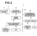
- FIG. 2 is a schematic block diagram illustrating the internal configuration of the image display device according to this embodiment.
- the image display device 1 includes a recording control unit 21, a compression/decompression processing unit 22, a frame memory 23, an internal memory 24, a three-dimensional processing unit 25, a display control unit 26 and a CPU 27.
- the recording control unit 21 controls recording and reading of information into and from the recording medium 4 inserted in the slot 5. Further, the recording control unit 21 writes stereoscopic effect control values based on the parallax level changed by the user, as will be described later, in tags of image files of the images GL and GR.
- the compression/decompression processing unit 22 carries out compression and decompression of the two images GL and GR to be stereoscopically displayed, which are read out from the recording medium 4.
- the frame memory 23 is a work memory for various processing operations including three-dimensional processing, which will be described later, to be applied to image data representing the images GL and GR.
- a dynamic RAM which is a volatile memory, is commonly used in view of costs.
- the internal memory 24 stores various constants to be set within the image display device 1, programs to be executed by the CPU 27, etc.
- a non-volatile memory is used so that the data stored therein is not lost when the power is turned off, and therefore, it is possible to record the photographed images in this memory.
- the three-dimensional processing unit 25 applies the three-dimensional processing to the images GL and GR to generate a stereoscopic image for stereoscopically displaying the images GL and GR on the LCD 2.
- the technique used in this embodiment to achieve the stereoscopic display may be any of known techniques.
- the images GL and GR may be displayed side by side to achieve the stereoscopic viewing through parallel viewing with naked eyes, or a lenticular system may be used, in which a lenticular lens is attached on the LCD 2, and the images GL and GR are displayed at predetermined positions on the display surface of the LCD 2 so that the images GL and GR are respectively viewed by the left and right eyes to achieve the stereoscopic display.
- a parallax barrier system may be used, in which a barrier for changing optical paths to the left and right eyes is attached on the LCD 2, and the images GL and GR are displayed at predetermined positions on the display surface of the LCD 2 so that the images GL and GR are respectively viewed by the left and right eyes to achieve the stereoscopic display.
- the stereoscopic display may also be achieved by combining the images GL and GR by overlapping the images GL and GR and changing the colours of the images GL and GR into colours different from each other, for example, red and blue (anaglyph system), or by overlapping the images GL and GR and providing different polarization directions of the images GL and GR (polarization filter system).
- a backlight control system may be used, which achieves the stereoscopic display by optically separating the optical paths of the backlights of the LCD 2 correspondingly to the left and right eyes in an alternating manner, and alternately displaying the images GL and GR on the display surface of the LCD 2 according to the separation of the backlights to the left and right.
- the LCD 2 is modified according to the type of the three-dimensional processing carried out by the three-dimensional processing unit 25.
- a lenticular lens is attached on the display surface of the LCD 2.
- a barrier is attached on the surface of the LCD 2.
- an optical element for changing directions of the rays from the left and right images is attached on the display surface of the LCD 2.
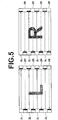
- the stereoscopic display is achieved using the backlight control system. Therefore, the LCD 2 includes backlights 2L for the left eye and backlights 2R for the right eye, as shown in FIG. 3 .
- optical paths of the backlights 2L for the left eye are indicated by solid lines
- optical paths of the backlights 2R for the right eye are indicated by dashed lines.
- the three-dimensional processing unit 25 applies image processing, such as white balance correction, tone correction, sharpness correction and colour correction, to the images GL and GR. It should be noted that a separate image processing unit for applying the image processing may be provided besides the three-dimensional processing unit 25.
- the three-dimensional processing unit 25 changes the parallax level of the images GL and GR to regenerate a stereoscopic image G3 according to the stereoscopic effect controlled by the user via the manual operation button 3, as will be described later, and stereoscopically displays the regenerated stereoscopic image G3.
- the display control unit 26 stereoscopically displays the stereoscopic image G3 obtained through the three-dimensional processing or two-dimensionally displays the images GL and GR overlapped with each other, according to an instruction made by the user via the manual operation button 3.
- an operation to turn on the backlights 2L for the left eye and display the image GL for the left eye and an operation to turn on the backlights 2R for the right eye and display the image GR for the right eye are continuously switched at a high rate (for example, 60 Hz) to provide the stereoscopic effect using the afterimage effect (three-dimensional mode).
- a high rate for example, 60 Hz
- turned-off backlights are indicated with hatching.
- the displayed image GL or GR is represented by the symbol "L" or "R".
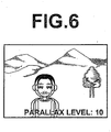
- the backlights 2L and 2R for the left and right eyes are simultaneously turned on, as shown in FIG. 5 , and display of the image GL for the left eye and display of the image GR for the right eye are continuously switched at a high speed to effect overlapped display of the two images GL, GR, as shown in FIG. 6 (two-dimensional mode).
- the CPU 27 controls the units of the image display device 1 according to instructions entered via the manual operation button 3.
- a data bus 28 is connected to the units and the CPU 27 forming the image display device 1 for communication of various data and information in the image display device 1.
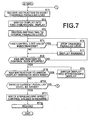
- FIG. 7 is a flow chart illustrating a process that is carried out during the stereoscopic effect control, i.e., changing the parallax level, in the embodiment.
- the three-dimensional processing has been applied to the images GL and GR read out from recording medium 4 without changing the parallax level, and the thus generated stereoscopic image G3 is stereoscopically displayed on the LCD 2.
- the CPU 27 starts the process when the stereoscopic image G3 is stereoscopically displayed, and receives an instruction to start changing the parallax level made by the user via the manual operation button 3 (step ST1).
- the instruction to start changing the parallax level is made via the centre button 3C, for example, of the manual operation button 3.
- the display control unit 26 switches the display dimension of the currently displayed image into two-dimensional display (step ST2).
- the two images GL and GR are two-dimensionally displayed on the LCD 2 so that they appear as being overlapped with each other.
- the parallax level between the two images GL and GR may be displayed during the two-dimensional display.
- a text "parallax level: 10" is displayed.
- the CPU 27 receives an instruction to change the parallax level made by the user via the manual operation button 3 (step ST3).
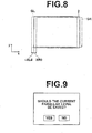
- FIG. 8 is a diagram for explaining how the parallax level is changed.
- the solid line indicates a display range of the LCD 2
- the dashed line indicates the image GL
- the dashed-dotted line indicates the image GR.
- the image GL is deviated from a predetermined parallax reference by an amount of -XLO
- the image GR is deviated from the parallax reference by an amount of XR0.
- the images GL and GR and the LCD 2 actually have the same size in the longitudinal direction, they are shown with different sizes in the longitudinal direction for the convenience of explanation.
- stereoscopic viewing can be provided by applying the three-dimensional processing to the images GL and GR to generate a stereoscopic image and stereoscopically displaying the stereoscopic image.
- step ST4 determines whether or not the parallax level has been changed to reach a control limit value.
- the control limit value of the parallax level refers to a control value at which, for example, each of the images GL and GR is shifted to reach an opposite end of the other image. If the determination in step ST4 is negative, then, determination is made as to whether or not the user has released the manual operation button 3 to stop the instruction to control (step ST5). If the determination in step ST5 is negative, the process returns to step ST4.
- step ST6 changing of the parallax level is stopped (step ST6), and a warning indicating that no further change can be made to the stereoscopic effect is displayed on the LCD 2 (step ST7), and the process proceeds to step ST5.
- changing of the parallax level is continued to achieve the instructed parallax level until the parallax level reaches the control limit value or the user releases the manual operation button 3.
- step ST8 determines whether or not an instruction to switch the display dimension is made via the manual operation button 3 (step ST8).
- the instruction to switch the display dimension may be made via the centre button 3C, for example, of the manual operation button 3. If the determination in step ST8 is affirmative, the display control unit 26 switches the display dimension of the image into the stereoscopic display (step ST9), and the process returns to step ST8.
- step ST8 If no instruction to switch the display dimension is made within a predetermined period of time, negative determination is made in step ST8, and the CPU 27 displays a query screen for determining whether or nor the current parallax level should be saved, as shown in FIG. 9 , on the LCD 2 (step ST10).
- the operation in step ST10 may be carried out immediately after the display dimension of the image is switched into the stereoscopic display in response to the user's operation of the centre button 3C. The user can select "YES” or “NO” via the manual operation button 3. If "NO” is selected, the process returns to step ST1.
- the recording control unit 21 writes the current parallax level as the stereoscopic effect control values in the headers of the images GL and GR (step ST11) and records the images GL and GR in the recording medium 4 (step ST12), and the process ends.
- the images GL and GR recorded in the recording medium 4 are overwritten with the images GL and GR having the stereoscopic effect control values written in the headers thereof.
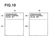
- FIG. 10 is a diagram illustrating the file structure of the image files of the images GL and GR having the stereoscopic effect control values written in the headers thereof.
- the image files FL and FR of the images GL and GR include headers HL and HR and main images (denoted by the same symbols GL and GR as the images), which are substantial data of the images GL and GR.
- the headers HL and HR contain descriptions of the stereoscopic effect control values.
- the header HL of the image GL contains a description "XL1" as the stereoscopic effect control value
- the header HR of the image GR contains a description "XR1" as the stereoscopic effect control value.
- the stereoscopic effect control values may be calculated in a manner that is most convenient for the system used.
- step ST8 the determination is made in step ST8 as to whether the instruction to switch the display dimension is made, and if the instruction to switch is made, the display dimension of the image is switched to the stereoscopic display.
- the display dimension of the image may be switched to the stereoscopic display when a predetermined period of time has elapsed after the instruction to control is stopped.
- FIG. 11 is a flow chart illustrating the process that is carried out during the stereoscopic display.
- the CPU 27 starts the process, and the recording control unit 21 reads out the images GL and GR to be displayed from the recording medium 4 and temporarily stores the images GL and GR in the frame memory 23 (step ST21). Then, the three-dimensional processing unit 25 determines whether or not the stereoscopic effect control values are written in the headers of the images GL and GR (step ST22).
- step ST22 If the determination in step ST22 is affirmative, the stereoscopic effect control values written in the headers of the images GL and GR are read out (step ST23), and the three-dimensional processing is applied to the images GL and GR to generate the stereoscopic image G3 with changing the parallax level to achieve the parallax level based on the read out stereoscopic effect control values (step ST24). Then, the display control unit 26 stereoscopically displays the stereoscopic image G3 on the LCD 2 (step ST25), and the process ends.
- step ST22 determines whether the three-dimensional processing is applied to the images GL and GR to generate the stereoscopic image G3 without changing the parallax level. Then, the process proceeds to step ST25 to stereoscopically display the stereoscopic image G3, and the process ends.
- the stereoscopic display of the images GL and GR is switched to the two-dimensional display during changing the parallax level. This makes it easier for the user to check the parallax level between the images GL and GR.
- the stereoscopic effect control values are written in the headers of the original images GL and GR before subjected to the three-dimensional processing and are recorded in the recording medium 4.
- the three-dimensional processing is again applied to the original images GL and GR to change the stereoscopic effect.
- the stereoscopic effect control values are written in the headers HL and HR of the image files FL and FR of the images GL and GR. Therefore, by applying the three-dimensional processing to achieve the parallax level based on the stereoscopic effect control values written in the headers HL and HR, the images GL and GR can be stereoscopically displayed to have a stereoscopic effect according to the preference of the user who has changed the parallax level. This eliminates the need of changing the parallax level by the user each time the stereoscopic display is carried out, thereby reducing the burden on the user.
- the stereoscopic display is achieved using the backlight control system in the above-described embodiment
- the stereoscopic display system is a system other than the backlight control system, such as a lenticular system or a parallax barrier system
- the,two-dimensional display is achieved by displaying the images GL and GR overlapped each other in a semi-transparent state without applying the three-dimensional processing, so that the two images GL and GR appear as being overlapped, as shown in FIG. 6 .
- a larger parallax level of the images GL and GR provides a narrower overlapping area between the images GL and GR, resulting in a narrower display range for the stereoscopic display. That is, as shown in FIG. 12 , when the parallax level of the images GL and GR is small, the display range of the images GL and GR, where the images overlap with each other, is as indicated by an area A1 shown in FIG. 12 , and when the parallax level is larger, the display range of the images GL and GR, where the images overlap with each other, is smaller than that when the parallax level is small, as indicated by an area A2. It should be noted that the images GL and GR and the areas A1 and A2 have the same aspect ratio.
- the stereoscopic display is carried out using the overlapping range between the images GL and GR. Therefore, the larger the parallax level, the smaller the area trimmed out from the images GL and GR for the stereoscopic display. As a result, the stereoscopic image G3 stereoscopically displayed on the LCD 2 is enlarged.
- the stereoscopically displayed stereoscopic image G3 may be enlarged or reduced to change the size thereof depending on the parallax level.
- the change of the display size of the image may catch the user's eyes and may hinder the user from determining an appropriate parallax level.
- a black frame as shown in FIG. 13 , may be added around the stereoscopically displayed stereoscopic image depending on the amount of change of the parallax level to provide indication of an actual display range on the LCD 2 during the stereoscopic display, i.e., the range of the images GL and GR to be trimmed out.
- the user can concentrate on control of the parallax level, and thus can efficiently control the parallax level.
- the frame may also be added during the two-dimensional display in the similar manner as during the stereoscopic display.
- the colour of the frame may be changed to notify the user to that effect.
- the colour of the frame may be changed stepwise according to the magnitude of the parallax level, such as to blue, to yellow and to red as the parallax level increases.
- the colour of the area with zero parallax in the stereoscopic image G3 may be changed so that the user can tell the area with zero parallax.
- the colour of the person's face may be changed into a predetermined colour (red, for example).
- the colour change is indicated by hatching. With this, the user can easily recognize the area with zero parallax.
- the colour of the area with zero parallax in the stereoscopic image G3 may be changed.
- the user may also be notified of the fact with a sound.
- an image file F1 containing the connected images GL and GR may be formed.
- the stereoscopic effect control values of the images GL and GR may be written in a header H1 of the image file F1.
- the images GL and GR and the stereoscopic effect control values may be stored as separate files.
- the image files FL and FR of the images GL and GR and a text file T1 with the stereoscopic effect control values written therein may be stored in a folder D1.
- a copy of the image files FL and FR of the original images GL and GR may be stored in the same folder D1 together with the text file T1, or the original images GL and GR may be moved from the folder where they were stored so that the original images GL and GR are stored in the same folder D1 as the text file T1.
- two or more image files F1 and F1' and the text file T1 with the stereoscopic effect control values written therein may be stored in the same folder D1.
- the stereoscopic effect control values for all the images stored in the folder D1 are written in the text file T1 with being associated with the image files F1 and F1'.
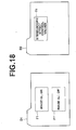
- the folder D1 may store only the image files F1 and F1', and a separate folder D2 may store a text file T0 with the stereoscopic effect control values written therein.
- the stereoscopic effect control values for all the images stored in the folder D1 are written in the text file T0 with being associated with the image files F1 and F1'.
- the images are read out from the recording medium 4 to be fed to the image display device 1 in the above-described embodiment, the invention is not limited to this.
- the images may be fed from an image server which is connected to the image display device 1 via a network, or the images may be fed via non-contact communication, etc.
- the image display device 1 may be applied to a photographing device including two or more photographing units.
- two or more images obtained through photographing can immediately be displayed on the monitor to allow changing the parallax level before the images are recorded in the recording medium 4.
- the parallax level may be changed with the display dimension being switched into the two-dimensional display, and then, when the user half-presses the release button, the display dimension of the image may be switched to the stereoscopic display. Further, the display dimension of the image may be switched to the stereoscopic display when a predetermined period of time has elapsed after the parallax level is changed.
- the device 10 has been described.
- the invention may be implemented as a program for causing a computer to function as means corresponding to the three-dimensional processing unit 25, the recording control unit 21 and the display control unit 26 to carry out the processes as shown in FIGS. 7 and 11 .
- the invention may also be implemented as a computer-readable recording medium containing such a program.
Abstract
Description
- The present invention relates to an image display device and method for stereoscopically displaying a stereoscopic image generated from two or more images to allow stereoscopic viewing of the image, as well as a program for causing a computer to carry out the image display method.
- It has been known to provide stereoscopic viewing using parallax, by combining two or more images, which are obtained through photographing the same subject from different positions, to generate a stereoscopic image, and stereoscopically displaying the thus generated stereoscopic image. As a specific example of a technique to achieve the stereoscopic display, parallel viewing with naked eyes is known, where the stereoscopic display is achieved by arranging the two or more images side by side. Further, the stereoscopic display may be achieved by generating a stereoscopic image by combining the two or more images, for example, by overlapping the images while changing the colours of the images into colours different from each other, such as red and blue (anaglyph system), or by overlapping the images with providing different polarization directions of the images (polarization filter system). In these cases, the stereoscopic viewing is effected by using image separating glasses, such as red-and-blue glasses or polarization glasses, to provide a merged view, which is attained via the automatic focusing function of the eyes, of the stereoscopically displayed stereoscopic image.
- Stereoscopic viewing can also be achieved without using the polarization glasses, etc, by displaying the two or more images on a stereoscopic display monitor which allows the stereoscopic viewing of the images, such as in a parallax barrier system or a lenticular system. In this case, the stereoscopic display is achieved by cutting the two or more images into vertical strips and arranging the strips alternately to generate a stereoscopic image, and disposing a light shielding barrier having slits. Further, a method for providing the stereoscopic display using afterimage effect has been proposed, in which left and right images are alternately displayed by being switched at a high speed with changing the direction of rays from the left and right images through the use of image separation glasses or attaching an optical element on a liquid crystal display (backlight control system).
- When the stereoscopic viewing is provided as described above, a preferred level of stereoscopic effect varies among users who view the stereoscopic images. Since the stereoscopic effect changes depending on an amount of disparity (parallax) between the two or more images for stereoscopic viewing, a technique to generate a stereoscopic image has been proposed, which involves receiving an instruction to control the parallax level of the stereoscopic image while the image is stereoscopically displayed, and generating a modified stereoscopic image according to the instructed parallax level (see Japanese Unexamined Patent Publication No.
2004-129186 10(1998)-090814 9(1997)-192349 - In the techniques disclosed in
Patent Documents 1 to 3, however, although the stereoscopic effect can be changed by adjusting the parallax level, adjustment of the stereoscopic effect is performed with the user viewing the stereoscopically displayed image, and therefore the amount of change of the parallax level is not readily recognized. - In view of the above-described circumstances, at least the preferred embodiments of the present invention are directed to allowing to facilitate checking the parallax level during adjustment of the stereoscopic effect of stereoscopic images.
- According to a first aspect of the present invention, there is provided an image display device which includes: display means capable of stereoscopically displaying a stereoscopic image generated from two or more images obtained through photographing from different positions; three-dimensional processing means for applying three-dimensional processing for stereoscopic display to the two or more images to generate the stereoscopic image; input means for receiving an instruction to start changing a parallax level of the stereoscopic image and an instruction to change the parallax level; and display control means for switching stereoscopic display of the stereoscopic image into two-dimensional display of the two or more images overlapped with each other in response to the instruction to start changing the parallax level, and two-dimensionally displaying the two or more images with changing the parallax level of the images in response to the instruction to change the parallax level.
- Preferably, in a case where the stereoscopic display is achieved using a backlight control system and the display means is a liquid crystal display means, the display control means drives backlights of the display means in a three-dimensional mode during the stereoscopic display and drives the backlights in a two-dimensional mode during the two-dimensional display.
- Preferably, when the instruction to change the parallax level is received, the display control means displays a display range of the two or more images during the stereoscopic display in a visually recognizable manner on the display means according to an amount of change of the parallax level.
- The description "a display range of the two or more images during the stereoscopic display in a visually recognizable manner" herein means providing the user with visual recognition of the size of the display range during the stereoscopic display before and after changing the parallax level, without changing the size of the two or more images, for example, by adding a frame around the displayed image and changing the size of the frame, without changing the display size of the two or more images.
- In a further preferred form, the image display device further includes notifying means for notifying, in a case where an area with substantially zero parallax between the two or more images is present, of the fact that the area with substantially zero parallax is present.
- The "notifying" herein may be achieved by changing the colour of the area with zero parallax in the two-dimensionally displayed images, or with a sound which indicates that an area with substantially zero parallax is present.
- The image display device according to the invention may further include recording control means for recording an amount of change of the parallax level according to the instruction in a recording medium with the amount of change of the parallax level being associated with the two or more images.
- In the image display device according to the invention, the display control means may switch, after the switching into the two-dimensional display, the two-dimensional display into the stereoscopic display when a predetermined operation is received.
- Further, in the image display device according to the invention, the display control means may switch, after the switching into the two-dimensional display, the two-dimensional display into the stereoscopic display when a predetermined period of time has elapsed.
- In a further preferred form of the image display device, the display control means may display the parallax level during the two-dimensional display.
- According to a second aspect of the present invention, there is provided a photographing apparatus which includes: two or more photographing means for obtaining two or more images for stereoscopic display through photographing from different positions; and the image display device according to the invention.
- According to a third aspect of the present invention, there is provided an image display method which includes the steps of: generating a stereoscopic image by applying three-dimensional processing to two or more images, the two or more images obtained through photographing from different positions; stereoscopically displaying the stereoscopic image; receiving an instruction to start changing a parallax level of the stereoscopic image; switching stereoscopic display of the stereoscopic image into two-dimensional display of the two or more images overlapped with each other in response to the instruction to start changing the parallax level; receiving an instruction to change the parallax level; and two-dimensionally displaying the two or more images with changing the parallax level of the images in response to the instruction to change the parallax level.
- The invention may be provided in the form of a program for causing a computer to carry out the image display method of the invention.
- According to the invention, when an instruction to change the parallax level is made by the user, stereoscopic display of the two or more images is switched into two-dimensional display of the two or more images overlapped with each other. This allows the user to check the level of parallax between the two or more images when the user adjusts the stereoscopic effect by changing the parallax level.
- The stereoscopic display is achieved using an overlapping range between the two or more images. Therefore, the larger the parallax level, the smaller the area trimmed out from the two or more images for the stereoscopic display. As a result, the stereoscopic image to be stereoscopically displayed is enlarged from the original images. However, in this case, the change of the display size of the image may catch the user's eyes and may hinder the user from determining an appropriate parallax level.
- By displaying the display range of the two or more images in a visually recognizable manner according to the amount of change of the parallax level, the displayed image is not enlarged. With this, the user can concentrate on control of the parallax level, and thus can efficiently control the parallax level.
- Further, when an area with zero parallax between the two or more images is present, the fact is notified. This allows the user to efficiently carry out the operation when the user wishes to provide a desired area with zero parallax between the images.
- Furthermore, the instructed amount of change of the parallax level is stored with being associated with the original images before subjected to the three-dimensional processing. Thus, when it is desired to change the stereoscopic effect later, the three-dimensional processing is applied again to the original images to change the stereoscopic effect.
- Preferred embodiments of the invention will now be described by way of example only and with reference to the accompanying drawings, in which
-
FIG. 1 is a perspective view illustrating the appearance of an image display device according to an embodiment of the present invention; -
FIG. 2 is a schematic block diagram illustrating the internal configuration of the image display device according to the embodiment of the invention; -
FIG. 3 is a diagram illustrating the structure of backlights of an LCD of a backlight control system; -
FIG. 4 is a diagram for explaining stereoscopic display with the backlight control system; -
FIG. 5 is a diagram for explaining two-dimensional display with the backlight control system; -
FIG. 6 is a diagram illustrating a two-dimensionally displayed state; -
FIG. 7 is a flow chart illustrating a process that is carried out during stereoscopic effect control in the embodiment of the invention; -
FIG. 8 is a diagram for explaining how a parallax level is changed; -
FIG. 9 is a diagram illustrating a query screen for determining whether or not a current parallax level should be saved; -
FIG. 10 is a diagram illustrating the file structure of image files having stereoscopic effect control values written in headers thereof; -
FIG. 11 is a flow chart illustrating a process that is carried out during stereoscopic display; -
FIG. 12 is a diagram for explaining how a trimming area is changed depending on a parallax level; -
FIG. 13 is a diagram illustrating a state where a black frame is added around a stereoscopic image; -
FIG. 14 is a diagram illustrating a state where a colour at an area with zero parallax is changed; -
FIG. 15 is a diagram illustrating the file structure of an image file including two connected images; -
FIG. 16 is a diagram illustrating how the image files and a text file of the stereoscopic effect control values are stored; -
FIG. 17 is another diagram illustrating how the image files and the text file of the stereoscopic effect control values are stored; and -
FIG. 18 is still another diagram illustrating how the image files and the text file of the stereoscopic effect control values are stored. - Hereinafter, an embodiment of the present invention will be described with reference to the drawings.
FIG. 1 is a perspective view illustrating the appearance of an image display device according to the embodiment of the invention. As shown inFIG. 1 , theimage display device 1 according to this embodiment includes a liquid crystal display (LCD) 2 and amanual operation button 3 at the front side thereof. Theimage display device 1 further includes, on a lateral side thereof, aslot 5 for receiving arecording medium 4, such as a memory card. Theimage display device 1 according to this embodiment stereoscopically displays, on theLCD 2, a stereoscopic image generated from two or more images, which have been obtained by photographing the same subject from different positions and are recorded in therecording medium 4. In the description of this embodiment, it is assumed that the stereoscopic display is carried out using two images GL and GR. The image GL is the image for the left eye and the image GR is the image for the right eye during the stereoscopic display. - The
manual operation button 3 includes anupper button 3U, alower button 3D, aleft button 3L, aright button 3R and acentre button 3C. -
FIG. 2 is a schematic block diagram illustrating the internal configuration of the image display device according to this embodiment. As shown inFIG. 2 , theimage display device 1 includes arecording control unit 21, a compression/decompression processing unit 22, aframe memory 23, aninternal memory 24, a three-dimensional processing unit 25, adisplay control unit 26 and aCPU 27. - The
recording control unit 21 controls recording and reading of information into and from therecording medium 4 inserted in theslot 5. Further, therecording control unit 21 writes stereoscopic effect control values based on the parallax level changed by the user, as will be described later, in tags of image files of the images GL and GR. - The compression/
decompression processing unit 22 carries out compression and decompression of the two images GL and GR to be stereoscopically displayed, which are read out from therecording medium 4. A tag storing the stereoscopic effect control values, which will be described later, and associated information, such as photographing time and date, is added to the image files of images GL and GR, based on the Exif format, for example. - The
frame memory 23 is a work memory for various processing operations including three-dimensional processing, which will be described later, to be applied to image data representing the images GL and GR. As theframe memory 23, a dynamic RAM, which is a volatile memory, is commonly used in view of costs. - The
internal memory 24 stores various constants to be set within theimage display device 1, programs to be executed by theCPU 27, etc. As theinternal memory 24, a non-volatile memory is used so that the data stored therein is not lost when the power is turned off, and therefore, it is possible to record the photographed images in this memory. - The three-
dimensional processing unit 25 applies the three-dimensional processing to the images GL and GR to generate a stereoscopic image for stereoscopically displaying the images GL and GR on theLCD 2. The technique used in this embodiment to achieve the stereoscopic display may be any of known techniques. For example, the images GL and GR may be displayed side by side to achieve the stereoscopic viewing through parallel viewing with naked eyes, or a lenticular system may be used, in which a lenticular lens is attached on theLCD 2, and the images GL and GR are displayed at predetermined positions on the display surface of theLCD 2 so that the images GL and GR are respectively viewed by the left and right eyes to achieve the stereoscopic display. Further, a parallax barrier system may be used, in which a barrier for changing optical paths to the left and right eyes is attached on theLCD 2, and the images GL and GR are displayed at predetermined positions on the display surface of theLCD 2 so that the images GL and GR are respectively viewed by the left and right eyes to achieve the stereoscopic display. - The stereoscopic display may also be achieved by combining the images GL and GR by overlapping the images GL and GR and changing the colours of the images GL and GR into colours different from each other, for example, red and blue (anaglyph system), or by overlapping the images GL and GR and providing different polarization directions of the images GL and GR (polarization filter system). Further, a backlight control system may be used, which achieves the stereoscopic display by optically separating the optical paths of the backlights of the
LCD 2 correspondingly to the left and right eyes in an alternating manner, and alternately displaying the images GL and GR on the display surface of theLCD 2 according to the separation of the backlights to the left and right. - The
LCD 2 is modified according to the type of the three-dimensional processing carried out by the three-dimensional processing unit 25. For example, in the case where the stereoscopic display is implemented with the lenticular system, a lenticular lens is attached on the display surface of theLCD 2. In the case of the parallax barrier system, a barrier is attached on the surface of theLCD 2. In the case of the backlight control system, an optical element for changing directions of the rays from the left and right images is attached on the display surface of theLCD 2. In this embodiment, the stereoscopic display is achieved using the backlight control system. Therefore, theLCD 2 includesbacklights 2L for the left eye and backlights 2R for the right eye, as shown inFIG. 3 . In the following description, optical paths of thebacklights 2L for the left eye are indicated by solid lines, and optical paths of thebacklights 2R for the right eye are indicated by dashed lines. - The three-
dimensional processing unit 25 applies image processing, such as white balance correction, tone correction, sharpness correction and colour correction, to the images GL and GR. It should be noted that a separate image processing unit for applying the image processing may be provided besides the three-dimensional processing unit 25. - The three-
dimensional processing unit 25 changes the parallax level of the images GL and GR to regenerate a stereoscopic image G3 according to the stereoscopic effect controlled by the user via themanual operation button 3, as will be described later, and stereoscopically displays the regenerated stereoscopic image G3. - The
display control unit 26 stereoscopically displays the stereoscopic image G3 obtained through the three-dimensional processing or two-dimensionally displays the images GL and GR overlapped with each other, according to an instruction made by the user via themanual operation button 3. - Namely, when the stereoscopic display is carried out, an operation to turn on the
backlights 2L for the left eye and display the image GL for the left eye and an operation to turn on thebacklights 2R for the right eye and display the image GR for the right eye, as shown inFIG. 4 , are continuously switched at a high rate (for example, 60 Hz) to provide the stereoscopic effect using the afterimage effect (three-dimensional mode). InFIG. 4 , turned-off backlights are indicated with hatching. The displayed image GL or GR is represented by the symbol "L" or "R". - On the other hand, when the two-dimensional display is carried out, the
backlights FIG. 5 , and display of the image GL for the left eye and display of the image GR for the right eye are continuously switched at a high speed to effect overlapped display of the two images GL, GR, as shown inFIG. 6 (two-dimensional mode). - The
CPU 27 controls the units of theimage display device 1 according to instructions entered via themanual operation button 3. - A
data bus 28 is connected to the units and theCPU 27 forming theimage display device 1 for communication of various data and information in theimage display device 1. - Next, a process carried out in this embodiment will be described.
FIG. 7 is a flow chart illustrating a process that is carried out during the stereoscopic effect control, i.e., changing the parallax level, in the embodiment. In this description, it is assumed that the three-dimensional processing has been applied to the images GL and GR read out from recordingmedium 4 without changing the parallax level, and the thus generated stereoscopic image G3 is stereoscopically displayed on theLCD 2. TheCPU 27 starts the process when the stereoscopic image G3 is stereoscopically displayed, and receives an instruction to start changing the parallax level made by the user via the manual operation button 3 (step ST1). The instruction to start changing the parallax level is made via thecentre button 3C, for example, of themanual operation button 3. With this, thedisplay control unit 26 switches the display dimension of the currently displayed image into two-dimensional display (step ST2). As shown inFIG. 6 , the two images GL and GR are two-dimensionally displayed on theLCD 2 so that they appear as being overlapped with each other. It should be noted that the parallax level between the two images GL and GR may be displayed during the two-dimensional display. In the example shown inFIG. 6 , a text "parallax level: 10" is displayed. Further, theCPU 27 receives an instruction to change the parallax level made by the user via the manual operation button 3 (step ST3). -
FIG. 8 is a diagram for explaining how the parallax level is changed. InFIG. 8 , the solid line indicates a display range of theLCD 2, the dashed line indicates the image GL, and the dashed-dotted line indicates the image GR. As shown in the drawing, the image GL is deviated from a predetermined parallax reference by an amount of -XLO and the image GR is deviated from the parallax reference by an amount of XR0. Although the images GL and GR and theLCD 2 actually have the same size in the longitudinal direction, they are shown with different sizes in the longitudinal direction for the convenience of explanation. Since the images GL and GR are obtained by photographing the same subject from different positions, there is a predetermined parallax (XRO + XL0 in the example shown inFIG. 8 ) between the images of the subject contained in the images GL and GR, as can be seen when the images GL and GR are overlapped with each other. Therefore, stereoscopic viewing can be provided by applying the three-dimensional processing to the images GL and GR to generate a stereoscopic image and stereoscopically displaying the stereoscopic image. - However, since a preferred level of the stereoscopic effect varies among users, the instruction to change the parallax level made by the user via the
manual operation button 3 is received, and the parallax level of the images GL and GR is changed in this embodiment. For example, in this embodiment, the parallax level is changed such that a smaller parallax level is provided when theleft button 3L of themanual operation button 3 is pressed, and a larger parallax level is provided when theright button 3R is pressed. In the case where the parallax level is displayed, the displayed parallax level is changed when theright button 3R or theleft button 3L is pressed. - Subsequently, the
CPU 27 determines whether or not the parallax level has been changed to reach a control limit value (step ST4). The control limit value of the parallax level refers to a control value at which, for example, each of the images GL and GR is shifted to reach an opposite end of the other image. If the determination in step ST4 is negative, then, determination is made as to whether or not the user has released themanual operation button 3 to stop the instruction to control (step ST5). If the determination in step ST5 is negative, the process returns to step ST4. If the determination in step ST4 is affirmative, changing of the parallax level is stopped (step ST6), and a warning indicating that no further change can be made to the stereoscopic effect is displayed on the LCD 2 (step ST7), and the process proceeds to step ST5. In this manner, changing of the parallax level is continued to achieve the instructed parallax level until the parallax level reaches the control limit value or the user releases themanual operation button 3. - If the determination in step ST5 is affirmative, the
CPU 27 determines whether or not an instruction to switch the display dimension is made via the manual operation button 3 (step ST8). The instruction to switch the display dimension may be made via thecentre button 3C, for example, of themanual operation button 3. If the determination in step ST8 is affirmative, thedisplay control unit 26 switches the display dimension of the image into the stereoscopic display (step ST9), and the process returns to step ST8. - If no instruction to switch the display dimension is made within a predetermined period of time, negative determination is made in step ST8, and the
CPU 27 displays a query screen for determining whether or nor the current parallax level should be saved, as shown inFIG. 9 , on the LCD 2 (step ST10). It should be noted that, when the instruction to switch the display dimension is made, the operation in step ST10 may be carried out immediately after the display dimension of the image is switched into the stereoscopic display in response to the user's operation of thecentre button 3C. The user can select "YES" or "NO" via themanual operation button 3. If "NO" is selected, the process returns to step ST1. If "YES" is selected, therecording control unit 21 writes the current parallax level as the stereoscopic effect control values in the headers of the images GL and GR (step ST11) and records the images GL and GR in the recording medium 4 (step ST12), and the process ends. The images GL and GR recorded in therecording medium 4 are overwritten with the images GL and GR having the stereoscopic effect control values written in the headers thereof. -
FIG. 10 is a diagram illustrating the file structure of the image files of the images GL and GR having the stereoscopic effect control values written in the headers thereof. As shown inFIG. 10 , the image files FL and FR of the images GL and GR include headers HL and HR and main images (denoted by the same symbols GL and GR as the images), which are substantial data of the images GL and GR. The headers HL and HR contain descriptions of the stereoscopic effect control values. For example, the header HL of the image GL contains a description "XL1" as the stereoscopic effect control value, and the header HR of the image GR contains a description "XR1" as the stereoscopic effect control value. - The stereoscopic effect control values XL1 and XR1 are calculated from the parallax level. For example, when the parallax level is 6 and the parallax reference is set on the middle of the images GL and GR, the stereoscopic effect control values are XL1 = 3 and XR1 = 3. The parallax reference may be set on the image GL, and in this case, the stereoscopic effect control values are XL1 = 0, XR1 = 6. It should be noted that the method for calculating the stereoscopic effect control values is not limited to the above-described example. The stereoscopic effect control values may be calculated in a manner that is most convenient for the system used.
- In the above-described process, the determination is made in step ST8 as to whether the instruction to switch the display dimension is made, and if the instruction to switch is made, the display dimension of the image is switched to the stereoscopic display. However, the display dimension of the image may be switched to the stereoscopic display when a predetermined period of time has elapsed after the instruction to control is stopped.
- Next, a process carried out in this embodiment when the images GL and GR recorded in the
recording medium 4 are stereoscopically displayed is described.FIG. 11 is a flow chart illustrating the process that is carried out during the stereoscopic display. When an instruction to stereoscopically display the images is made via themanual operation button 3, theCPU 27 starts the process, and therecording control unit 21 reads out the images GL and GR to be displayed from therecording medium 4 and temporarily stores the images GL and GR in the frame memory 23 (step ST21). Then, the three-dimensional processing unit 25 determines whether or not the stereoscopic effect control values are written in the headers of the images GL and GR (step ST22). If the determination in step ST22 is affirmative, the stereoscopic effect control values written in the headers of the images GL and GR are read out (step ST23), and the three-dimensional processing is applied to the images GL and GR to generate the stereoscopic image G3 with changing the parallax level to achieve the parallax level based on the read out stereoscopic effect control values (step ST24). Then, thedisplay control unit 26 stereoscopically displays the stereoscopic image G3 on the LCD 2 (step ST25), and the process ends. - On the other hand, if the determination in step ST22 is negative, the three-dimensional processing is applied to the images GL and GR to generate the stereoscopic image G3 without changing the parallax level (step ST26). Then, the process proceeds to step ST25 to stereoscopically display the stereoscopic image G3, and the process ends.
- As described above, in this embodiment, the stereoscopic display of the images GL and GR is switched to the two-dimensional display during changing the parallax level. This makes it easier for the user to check the parallax level between the images GL and GR.
- Further, the stereoscopic effect control values are written in the headers of the original images GL and GR before subjected to the three-dimensional processing and are recorded in the
recording medium 4. Thus, if the user wants to change the stereoscopic effect at a later time, the three-dimensional processing is again applied to the original images GL and GR to change the stereoscopic effect. - Further, the stereoscopic effect control values are written in the headers HL and HR of the image files FL and FR of the images GL and GR. Therefore, by applying the three-dimensional processing to achieve the parallax level based on the stereoscopic effect control values written in the headers HL and HR, the images GL and GR can be stereoscopically displayed to have a stereoscopic effect according to the preference of the user who has changed the parallax level. This eliminates the need of changing the parallax level by the user each time the stereoscopic display is carried out, thereby reducing the burden on the user.
- It should be noted that, although the stereoscopic display is achieved using the backlight control system in the above-described embodiment, in a case where the stereoscopic display system is a system other than the backlight control system, such as a lenticular system or a parallax barrier system, the,two-dimensional display is achieved by displaying the images GL and GR overlapped each other in a semi-transparent state without applying the three-dimensional processing, so that the two images GL and GR appear as being overlapped, as shown in
FIG. 6 . - When the stereoscopic display is carried out, a larger parallax level of the images GL and GR provides a narrower overlapping area between the images GL and GR, resulting in a narrower display range for the stereoscopic display. That is, as shown in
FIG. 12 , when the parallax level of the images GL and GR is small, the display range of the images GL and GR, where the images overlap with each other, is as indicated by an area A1 shown inFIG. 12 , and when the parallax level is larger, the display range of the images GL and GR, where the images overlap with each other, is smaller than that when the parallax level is small, as indicated by an area A2. It should be noted that the images GL and GR and the areas A1 and A2 have the same aspect ratio. - The stereoscopic display is carried out using the overlapping range between the images GL and GR. Therefore, the larger the parallax level, the smaller the area trimmed out from the images GL and GR for the stereoscopic display. As a result, the stereoscopic image G3 stereoscopically displayed on the
LCD 2 is enlarged. In this embodiment, when the parallax level is changed, the stereoscopically displayed stereoscopic image G3 may be enlarged or reduced to change the size thereof depending on the parallax level. However, in this case, the change of the display size of the image may catch the user's eyes and may hinder the user from determining an appropriate parallax level. - Therefore, for example, a black frame, as shown in
FIG. 13 , may be added around the stereoscopically displayed stereoscopic image depending on the amount of change of the parallax level to provide indication of an actual display range on theLCD 2 during the stereoscopic display, i.e., the range of the images GL and GR to be trimmed out. With this, the user can concentrate on control of the parallax level, and thus can efficiently control the parallax level. - It should be noted that the frame may also be added during the two-dimensional display in the similar manner as during the stereoscopic display.
- If the parallax level is excessively large, appropriate stereoscopic viewing cannot be provided. Therefore, when the parallax level is too large to provide the stereoscopic viewing, the colour of the frame may be changed to notify the user to that effect. In this case, the colour of the frame may be changed stepwise according to the magnitude of the parallax level, such as to blue, to yellow and to red as the parallax level increases.
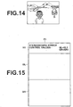
- Further, in the above-described embodiment, when the parallax level is changed, an area with zero parallax appears on the images GL and GR. In this case, the colour of the area with zero parallax in the stereoscopic image G3 may be changed so that the user can tell the area with zero parallax. For example, in the two-dimensionally displayed images GL and GR shown in
FIG. 14 , if the parallax level is zero at the person's face, the colour of the person's face may be changed into a predetermined colour (red, for example). InFIG. 14 , the colour change is indicated by hatching. With this, the user can easily recognize the area with zero parallax. Similarly, during the stereoscopic display, the colour of the area with zero parallax in the stereoscopic image G3 may be changed. - If there is an area with zero parallax, the user may also be notified of the fact with a sound.
- Although the stereoscopic effect control values are written in the headers HL and HR of the image files FL and FR of the images GL and GR in the above-described embodiment, in some cases, an image file F1 containing the connected images GL and GR, as shown in
FIG. 15 , may be formed. In this case, the stereoscopic effect control values of the images GL and GR may be written in a header H1 of the image file F1. - The images GL and GR and the stereoscopic effect control values may be stored as separate files. For example, as shown in
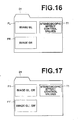
FIG. 16 , the image files FL and FR of the images GL and GR and a text file T1 with the stereoscopic effect control values written therein may be stored in a folder D1. In this case, a copy of the image files FL and FR of the original images GL and GR may be stored in the same folder D1 together with the text file T1, or the original images GL and GR may be moved from the folder where they were stored so that the original images GL and GR are stored in the same folder D1 as the text file T1. - In particular, in a case where the images GL and GR are stored as the single image file F1, as shown in
FIG. 17 , two or more image files F1 and F1' and the text file T1 with the stereoscopic effect control values written therein may be stored in the same folder D1. In this case, the stereoscopic effect control values for all the images stored in the folder D1 are written in the text file T1 with being associated with the image files F1 and F1'. - Further, as shown in
FIG. 18 , the folder D1 may store only the image files F1 and F1', and a separate folder D2 may store a text file T0 with the stereoscopic effect control values written therein. In this case, the stereoscopic effect control values for all the images stored in the folder D1 are written in the text file T0 with being associated with the image files F1 and F1'. - It should be noted that, although the images are read out from the
recording medium 4 to be fed to theimage display device 1 in the above-described embodiment, the invention is not limited to this. The images may be fed from an image server which is connected to theimage display device 1 via a network, or the images may be fed via non-contact communication, etc. - Further, the
image display device 1 according to the above-described embodiment may be applied to a photographing device including two or more photographing units. In this case, two or more images obtained through photographing can immediately be displayed on the monitor to allow changing the parallax level before the images are recorded in therecording medium 4. In this case, it is possible to change the parallax level while the live view image before photographing is displayed. In this case, the parallax level may be changed with the display dimension being switched into the two-dimensional display, and then, when the user half-presses the release button, the display dimension of the image may be switched to the stereoscopic display. Further, the display dimension of the image may be switched to the stereoscopic display when a predetermined period of time has elapsed after the parallax level is changed. - The
device 10 according to a preferred embodiment of the invention has been described. In addition, the invention may be implemented as a program for causing a computer to function as means corresponding to the three-dimensional processing unit 25, therecording control unit 21 and thedisplay control unit 26 to carry out the processes as shown inFIGS. 7 and11 . The invention may also be implemented as a computer-readable recording medium containing such a program.
Claims (9)
- A stereoscopic imaging apparatus comprising:two photographing means for obtaining two images for stereoscopic display through photographing from different positions;three-dimensional processing means for applying three-dimensional processing for stereoscopic display to the two images to generate the image which will be perceived stereoscopically;autostereoscopic display means capable of displaying an image generated from the said two images in a mode such that the displayed image will be perceived stereoscopically by a viewer or in a mode such that the displayed image will be perceived as two-dimensional;input means for receiving an instruction to change the amount of disparity between the two images, and thus the level of parallax; anddisplay control means for switching the display so that the displayed image will be perceived as two-dimensional, with the two images overlapped with each other, at least while the instruction to change the amount of disparity between the two images is inputted when the image is displayed so as to be perceived stereoscopically as a live view image, and two-dimensionally displaying the two images and changing the amount of disparity between the two images in response to the instruction to change the amount of disparity between the two images, and switching the display back so that the displayed image is displayed so as to be perceived stereoscopically when a predetermined period of time has elapsed after the instruction to change the amount of disparity between the two images is stopped.
- The stereoscopic imaging apparatus as claimed in claim 1, further comprising:a first determining means for determining whether the amount of disparity between the two images has been changed to reach a control limit value; anda second determining means for determining whether the instruction to change the amount of disparity between the two images has stopped;wherein the display control means continues to change the amount of disparity between the two images until an affirmative determination is made by one of the first determining means and the second determining means.
- The stereoscopic imaging apparatus as claimed in claim 1 or 2, wherein the display control means displays a numerical value indicating the amount of disparity between the two images, and thus the level of parallax, when the two images are displayed so as to be perceived as two-dimensional.
- The stereoscopic imaging apparatus as claimed in any of claims 1 to 3, wherein in a case where the display mode where the two images are displayed so as to be perceived stereoscopically is achieved using a backlight control system and the display means is a liquid crystal display means, the display control means drives backlights of the display means so as to be continuously switched at a high rate in a display mode where the two images are displayed so as to be perceived stereoscopically and drives the backlights to be simultaneously turned on in a display mode where the two images are displayed so as to be perceived as two-dimensional.
- The stereoscopic imaging apparatus as claimed in any of claims 1 to 4, wherein, when the instruction to change the amount of disparity is received, the display control means displays a display range of the two images during the stereoscopic display in a visually recognizable manner on the display means according to an amount of change of the disparity and thus of the parallax level.
- The stereoscopic imaging apparatus as claimed in any one of claims 1 to 5, further comprising notifying means for notifying, in a case where an area with substantially zero parallax between the two images is present, the fact that the area with substantially zero parallax is present.
- The stereoscopic imaging apparatus as claimed in any one of claims 1 to 6, further comprising recording control means for recording an amount of change of the amount of disparity and thus of parallax level according to the instruction in a recording medium, with the amount of change of the amount of disparity and thus the parallax level being associated with the two or images.
- A stereoscopic imaging method comprising the steps of:obtaining two images through photographing from different positions;generating a stereoscopic image from the two images by applying three-dimensional processing for stereoscopic display to the two images to generate the image which will be perceived stereoscopically;stereoscopically displaying a live view of the stereoscopic image on an autostereoscopic display means capable of displaying an image generated from the said two images in a mode such that the displayed image will be perceived stereoscopically by a viewer or in a mode such that the displayed image will be perceived as two-dimensional;receiving an instruction to change the amount of disparity between the two images when the image is displayed so as to be perceived stereoscopically;changing from a display mode where the two images are displayed so as to be perceived stereoscopically as a live view image to a display mode where the two images are displayed so as to be perceived as two-dimensional, with the two images overlapped with each other, in response to the instruction to change the amount of disparity between the two images;displaying the two images so as to be perceived as two-dimensional and changing the amount of disparity between the two images in response to the instruction to change the amount of disparity; andchanging the display back so that the displayed image is displayed so as to be perceived stereoscopically when a predetermined period of time has elapsed after the instruction to change the amount of disparity between the two images is stopped.
- A program for causing a computer to carry out an image display method including generating a stereoscopic image by applying three-dimensional processing to two images, obtained through photographing from different positions, and stereoscopically displaying the stereoscopic image, the program being characterized by the method comprising the steps of:generating a stereoscopic image from the two images by applying three-dimensional processing for stereoscopic display to the two images to generate the image which will be perceived stereoscopically;stereoscopically displaying a live view of the stereoscopic image on an autostereoscopic display means capable of displaying an image generated from the said two images in a mode such that the displayed image will be perceived stereoscopically by a viewer or in a mode such that the displayed image will be perceived as two-dimensional;receiving an instruction to change the amount of disparity between the two images when the image is displayed so as to be perceived stereoscopically;changing from a display mode where the two images are displayed so as to be perceived stereoscopically as a live view image to a display mode where the two images are displayed so as to be perceived as two-dimensional, with the two images overlapped with each other, in response to the instruction to change the amount of disparity between the two images;displaying the two images so as to be perceived as two-dimensional and changing the amount of disparity between the two images in response to the instruction to change the amount of disparity; andchanging the display back so that the displayed image is displayed so as to be perceived stereoscopically when a predetermined period of time has elapsed after the instruction to change the amount of disparity between the two images is stopped.
Applications Claiming Priority (2)
| Application Number | Priority Date | Filing Date | Title |
|---|---|---|---|
| JP2009169664A JP5430266B2 (en) | 2009-07-21 | 2009-07-21 | Image display apparatus and method, and program |
| EP10251295.1A EP2293587B1 (en) | 2009-07-21 | 2010-07-20 | Image display device, method and program |
Related Parent Applications (2)
| Application Number | Title | Priority Date | Filing Date |
|---|---|---|---|
| EP10251295.1A Division-Into EP2293587B1 (en) | 2009-07-21 | 2010-07-20 | Image display device, method and program |
| EP10251295.1 Division | 2010-07-20 |
Publications (1)
| Publication Number | Publication Date |
|---|---|
| EP2466904A1 true EP2466904A1 (en) | 2012-06-20 |
Family
ID=42805506
Family Applications (3)
| Application Number | Title | Priority Date | Filing Date |
|---|---|---|---|
| EP10251295.1A Not-in-force EP2293587B1 (en) | 2009-07-21 | 2010-07-20 | Image display device, method and program |
| EP12001816A Ceased EP2469871A3 (en) | 2009-07-21 | 2010-07-20 | Image display device, method and program |
| EP12001817A Ceased EP2466904A1 (en) | 2009-07-21 | 2010-07-20 | Image display device, method and program |
Family Applications Before (2)
| Application Number | Title | Priority Date | Filing Date |
|---|---|---|---|
| EP10251295.1A Not-in-force EP2293587B1 (en) | 2009-07-21 | 2010-07-20 | Image display device, method and program |
| EP12001816A Ceased EP2469871A3 (en) | 2009-07-21 | 2010-07-20 | Image display device, method and program |
Country Status (4)
| Country | Link |
|---|---|
| US (2) | US10080013B2 (en) |
| EP (3) | EP2293587B1 (en) |
| JP (1) | JP5430266B2 (en) |
| CN (2) | CN103731656B (en) |
Families Citing this family (24)
| Publication number | Priority date | Publication date | Assignee | Title |
|---|---|---|---|---|
| JP4787369B1 (en) * | 2010-03-30 | 2011-10-05 | 富士フイルム株式会社 | Image processing apparatus and method, and program |
| JP5546960B2 (en) * | 2010-06-14 | 2014-07-09 | 任天堂株式会社 | Stereoscopic image display program, stereoscopic image display device, stereoscopic image display system, and stereoscopic image display method |
| KR20120010764A (en) * | 2010-07-27 | 2012-02-06 | 엘지전자 주식회사 | MOBILE TERMINAL AND METHOD FOR CONTROLLING A THREE DIMENSION IMAGE in thereof |
| KR20120011161A (en) * | 2010-07-28 | 2012-02-07 | 삼성전자주식회사 | Apparatus and method for altering images for three-dimensional display |
| JP5324537B2 (en) * | 2010-09-06 | 2013-10-23 | 富士フイルム株式会社 | Stereoscopic image display control device, operation control method thereof, and operation control program thereof |
| JP5324538B2 (en) * | 2010-09-06 | 2013-10-23 | 富士フイルム株式会社 | Stereoscopic image display control device, operation control method thereof, and operation control program thereof |
| JPWO2012033005A1 (en) * | 2010-09-08 | 2014-01-20 | 日本電気株式会社 | Imaging apparatus and imaging method |
| JP2012114896A (en) * | 2010-11-04 | 2012-06-14 | Panasonic Corp | Three-dimensional imaging apparatus and three-dimensional reproduction apparatus |
| CN103202027B (en) * | 2010-11-05 | 2016-01-20 | 富士胶片株式会社 | Image processing apparatus, image processing program, image processing method and storage medium |
| EP2506587A2 (en) * | 2011-03-31 | 2012-10-03 | Fujifilm Corporation | Stereoscopic display apparatus |
| JP5325255B2 (en) * | 2011-03-31 | 2013-10-23 | 富士フイルム株式会社 | Stereoscopic image display device, stereoscopic image display method, and stereoscopic image display program |
| JP6089383B2 (en) * | 2011-04-08 | 2017-03-08 | ソニー株式会社 | Image processing apparatus, image processing method, and program |
| CN102879993B (en) * | 2011-07-15 | 2015-06-10 | 时代光电科技股份有限公司 | Object outline probing device and method |
| US20130047186A1 (en) * | 2011-08-18 | 2013-02-21 | Cisco Technology, Inc. | Method to Enable Proper Representation of Scaled 3D Video |
| CN102427542B (en) * | 2011-09-28 | 2014-07-30 | 深圳超多维光电子有限公司 | Method and device for processing three-dimensional image and terminal equipment thereof |
| KR101850718B1 (en) * | 2011-12-15 | 2018-04-20 | 엘지전자 주식회사 | Display Apparatus and method for adjusting 3D image of the display apparatus |
| US20150116467A1 (en) * | 2011-12-28 | 2015-04-30 | Sony Corporation | Parallax adjustment device, image processing device, and frame format |
| JP5932363B2 (en) * | 2012-01-26 | 2016-06-08 | キヤノン株式会社 | Imaging apparatus and control method thereof |
| JP6004354B2 (en) * | 2012-06-15 | 2016-10-05 | パナソニックIpマネジメント株式会社 | Image data processing apparatus and image data processing method |
| TWI566576B (en) * | 2014-06-03 | 2017-01-11 | 宏碁股份有限公司 | Stereoscopic view synthesis method and apparatus using the same |
| CN104378621A (en) * | 2014-11-25 | 2015-02-25 | 深圳超多维光电子有限公司 | Processing method and device for three-dimensional scene |
| CN111684497A (en) * | 2018-02-06 | 2020-09-18 | 索尼公司 | Image processing apparatus, image processing method, and image providing system |
| US11314383B2 (en) * | 2019-03-24 | 2022-04-26 | Apple Inc. | Stacked media elements with selective parallax effects |
| US11770517B2 (en) * | 2019-10-28 | 2023-09-26 | Sony Group Corporation | Information processing apparatus and information processing method |
Citations (6)
| Publication number | Priority date | Publication date | Assignee | Title |
|---|---|---|---|---|
| JPH09192349A (en) | 1996-01-19 | 1997-07-29 | Taito Corp | Parallax adjustment device of game machine capable of visualizing three-dimensional image |
| JPH1090814A (en) | 1996-09-11 | 1998-04-10 | Canon Inc | Compound eye camera and image processing method |
| JP2004129186A (en) | 2002-07-31 | 2004-04-22 | Sharp Corp | Device and program for processing stereoscopic image data, and recording medium |
| US7102686B1 (en) * | 1998-06-05 | 2006-09-05 | Fuji Photo Film Co., Ltd. | Image-capturing apparatus having multiple image capturing units |
| US20080158346A1 (en) * | 2006-12-27 | 2008-07-03 | Fujifilm Corporation | Compound eye digital camera |
| US20090058878A1 (en) * | 2007-08-31 | 2009-03-05 | Fujifilm Corporation | Method for displaying adjustment images in multi-view imaging system, and multi-view imaging system |
Family Cites Families (26)
| Publication number | Priority date | Publication date | Assignee | Title |
|---|---|---|---|---|
| JP3283925B2 (en) * | 1992-09-29 | 2002-05-20 | 株式会社鷺宮製作所 | Digital display thermostat |
| JP3054002B2 (en) * | 1993-09-01 | 2000-06-19 | キヤノン株式会社 | Compound eye imaging device |
| KR100414629B1 (en) * | 1995-03-29 | 2004-05-03 | 산요덴키가부시키가이샤 | 3D display image generation method, image processing method using depth information, depth information generation method |
| JP3581745B2 (en) * | 1995-08-07 | 2004-10-27 | 公佑 橋本 | 3D image display device |
| JPH09130513A (en) * | 1995-11-02 | 1997-05-16 | Minolta Co Ltd | Image formation device |
| DE69733233T2 (en) * | 1996-09-11 | 2006-01-19 | Canon K.K. | Image processing for three-dimensional rendering of image data on the display of an image capture device |
| JP3802630B2 (en) * | 1996-12-28 | 2006-07-26 | オリンパス株式会社 | Stereoscopic image generating apparatus and stereoscopic image generating method |
| JP2001236521A (en) | 2000-02-22 | 2001-08-31 | Japan Science & Technology Corp | Virtual reality system based on image dividing system |
| JP2002006425A (en) * | 2000-06-20 | 2002-01-09 | Nippon Hoso Kyokai <Nhk> | Stereoscopic image photographic optical device |
| US7277121B2 (en) * | 2001-08-29 | 2007-10-02 | Sanyo Electric Co., Ltd. | Stereoscopic image processing and display system |
| JP3691444B2 (en) * | 2002-03-11 | 2005-09-07 | 三洋電機株式会社 | Stereo imaging device |
| WO2004030376A1 (en) * | 2002-09-27 | 2004-04-08 | Sharp Kabushiki Kaisha | 3-d image display unit, 3-d image recording device and 3-d image recording method |
| JP2004207933A (en) | 2002-12-25 | 2004-07-22 | Toshiba Corp | Crt display device and projection display device |
| JPWO2004084560A1 (en) * | 2003-03-20 | 2006-06-29 | 富田 誠次郎 | 3D image display system |
| EP1617684A4 (en) * | 2003-04-17 | 2009-06-03 | Sharp Kk | 3-dimensional image creation device, 3-dimensional image reproduction device, 3-dimensional image processing device, 3-dimensional image processing program, and recording medium containing the program |
| JP4181446B2 (en) * | 2003-05-14 | 2008-11-12 | シャープ株式会社 | Stereoscopic image display device |
| JP2004356772A (en) * | 2003-05-27 | 2004-12-16 | Sanyo Electric Co Ltd | Three-dimensional stereoscopic image display apparatus and program for providing three-dimensional stereoscopic display function to computer |
| JP2005026800A (en) * | 2003-06-30 | 2005-01-27 | Konica Minolta Photo Imaging Inc | Image processing method, imaging apparatus, image processing apparatus, and image recording apparatus |
| JP2005073038A (en) * | 2003-08-26 | 2005-03-17 | Casio Comput Co Ltd | Electronic equipment with three-dimensional display function |
| JP4212987B2 (en) | 2003-08-26 | 2009-01-21 | シャープ株式会社 | Stereoscopic image display apparatus, stereoscopic image display method, program for causing computer to execute the method, and recording medium recording the program |
| JP4251952B2 (en) * | 2003-10-01 | 2009-04-08 | シャープ株式会社 | Stereoscopic image display apparatus and stereoscopic image display method |
| JP4469159B2 (en) | 2003-11-06 | 2010-05-26 | 学校法人早稲田大学 | 3D image evaluation apparatus and 3D image tuner |
| JP4447407B2 (en) * | 2004-08-30 | 2010-04-07 | 株式会社リコー | Print processing device |
| JP5096048B2 (en) * | 2007-06-15 | 2012-12-12 | 富士フイルム株式会社 | Imaging apparatus, stereoscopic image reproduction apparatus, and stereoscopic image reproduction program |
| KR100927720B1 (en) * | 2007-08-24 | 2009-11-18 | 삼성모바일디스플레이주식회사 | Electronic imaging equipment |
| JP5266126B2 (en) * | 2009-03-31 | 2013-08-21 | 富士フイルム株式会社 | Image display apparatus and method, and program |
-
2009
- 2009-07-21 JP JP2009169664A patent/JP5430266B2/en not_active Expired - Fee Related
-
2010
- 2010-07-13 US US12/835,607 patent/US10080013B2/en not_active Expired - Fee Related
- 2010-07-20 EP EP10251295.1A patent/EP2293587B1/en not_active Not-in-force
- 2010-07-20 EP EP12001816A patent/EP2469871A3/en not_active Ceased
- 2010-07-20 EP EP12001817A patent/EP2466904A1/en not_active Ceased
- 2010-07-21 CN CN201410021543.1A patent/CN103731656B/en not_active Expired - Fee Related
- 2010-07-21 CN CN201010235639.XA patent/CN101964916B/en not_active Expired - Fee Related
-
2013
- 2013-03-15 US US13/833,237 patent/US9060170B2/en not_active Expired - Fee Related
Patent Citations (6)
| Publication number | Priority date | Publication date | Assignee | Title |
|---|---|---|---|---|
| JPH09192349A (en) | 1996-01-19 | 1997-07-29 | Taito Corp | Parallax adjustment device of game machine capable of visualizing three-dimensional image |
| JPH1090814A (en) | 1996-09-11 | 1998-04-10 | Canon Inc | Compound eye camera and image processing method |
| US7102686B1 (en) * | 1998-06-05 | 2006-09-05 | Fuji Photo Film Co., Ltd. | Image-capturing apparatus having multiple image capturing units |
| JP2004129186A (en) | 2002-07-31 | 2004-04-22 | Sharp Corp | Device and program for processing stereoscopic image data, and recording medium |
| US20080158346A1 (en) * | 2006-12-27 | 2008-07-03 | Fujifilm Corporation | Compound eye digital camera |
| US20090058878A1 (en) * | 2007-08-31 | 2009-03-05 | Fujifilm Corporation | Method for displaying adjustment images in multi-view imaging system, and multi-view imaging system |
Also Published As
| Publication number | Publication date |
|---|---|
| US10080013B2 (en) | 2018-09-18 |
| EP2469871A2 (en) | 2012-06-27 |
| US20110018968A1 (en) | 2011-01-27 |
| EP2469871A3 (en) | 2012-07-25 |
| JP2011024151A (en) | 2011-02-03 |
| JP5430266B2 (en) | 2014-02-26 |
| EP2293587A1 (en) | 2011-03-09 |
| EP2293587B1 (en) | 2014-12-03 |
| US20130201302A1 (en) | 2013-08-08 |
| CN101964916B (en) | 2014-02-26 |
| US9060170B2 (en) | 2015-06-16 |
| CN103731656A (en) | 2014-04-16 |
| CN103731656B (en) | 2016-01-20 |
| CN101964916A (en) | 2011-02-02 |
Similar Documents
| Publication | Publication Date | Title |
|---|---|---|
| EP2293587B1 (en) | Image display device, method and program | |
| EP2415273B1 (en) | Image display device and method as well as program | |
| JP4787905B1 (en) | Image processing apparatus and method, and program | |
| KR20090102705A (en) | Method, apparatus, and program for processing stereoscopic videos | |
| EP2107816A2 (en) | Stereoscopic display apparatus, stereoscopic display method, and program | |
| US8648953B2 (en) | Image display apparatus and method, as well as program | |
| JP5550791B2 (en) | Image processing apparatus, imaging apparatus, and parallax adjustment method | |
| EP2645726A1 (en) | Image processing device, image processing method, and image processing program | |
| JP5396877B2 (en) | Image processing apparatus, program, image processing method, and recording method | |
| US9369699B2 (en) | Stereoscopic image display device, stereoscopic imaging device, and methods | |
| US8849012B2 (en) | Image processing apparatus and method and computer readable medium having a program for processing stereoscopic image | |
| JP5659285B2 (en) | Display control apparatus and method, and program | |
| JP5894249B2 (en) | Display control apparatus and method, and program | |
| JP4819194B2 (en) | Compound eye photographing apparatus and method, and program | |
| JP4819195B2 (en) | Image display apparatus and method, and program | |
| JP4819196B2 (en) | Compound eye photographing apparatus and method, and program | |
| JP4516188B2 (en) | Image display device | |
| US20120236129A1 (en) | Imaging apparatus, imaging method and imaging system |
Legal Events
| Date | Code | Title | Description |
|---|---|---|---|
| PUAI | Public reference made under article 153(3) epc to a published international application that has entered the european phase |
Free format text: ORIGINAL CODE: 0009012 |
|
| AC | Divisional application: reference to earlier application |
Ref document number: 2293587 Country of ref document: EP Kind code of ref document: P |
|
| AK | Designated contracting states |
Kind code of ref document: A1 Designated state(s): AL AT BE BG CH CY CZ DE DK EE ES FI FR GB GR HR HU IE IS IT LI LT LU LV MC MK MT NL NO PL PT RO SE SI SK SM TR |
|
| 17P | Request for examination filed |
Effective date: 20121213 |
|
| 17Q | First examination report despatched |
Effective date: 20130308 |
|
| APBK | Appeal reference recorded |
Free format text: ORIGINAL CODE: EPIDOSNREFNE |
|
| APBN | Date of receipt of notice of appeal recorded |
Free format text: ORIGINAL CODE: EPIDOSNNOA2E |
|
| APBR | Date of receipt of statement of grounds of appeal recorded |
Free format text: ORIGINAL CODE: EPIDOSNNOA3E |
|
| APAF | Appeal reference modified |
Free format text: ORIGINAL CODE: EPIDOSCREFNE |
|
| APBT | Appeal procedure closed |
Free format text: ORIGINAL CODE: EPIDOSNNOA9E |
|
| STAA | Information on the status of an ep patent application or granted ep patent |
Free format text: STATUS: THE APPLICATION HAS BEEN REFUSED |
|
| 18R | Application refused |
Effective date: 20191030 |