EP2330480A1 - Adapting portable electrical devices to receive power wirelessly - Google Patents
Adapting portable electrical devices to receive power wirelessly Download PDFInfo
- Publication number
- EP2330480A1 EP2330480A1 EP11152593A EP11152593A EP2330480A1 EP 2330480 A1 EP2330480 A1 EP 2330480A1 EP 11152593 A EP11152593 A EP 11152593A EP 11152593 A EP11152593 A EP 11152593A EP 2330480 A1 EP2330480 A1 EP 2330480A1
- Authority
- EP
- European Patent Office
- Prior art keywords
- power
- receiving element
- portable electrical
- electrical device
- connectors
- Prior art date
- Legal status (The legal status is an assumption and is not a legal conclusion. Google has not performed a legal analysis and makes no representation as to the accuracy of the status listed.)
- Withdrawn
Links
- 239000000853 adhesive Substances 0.000 claims abstract description 17
- 230000001070 adhesive effect Effects 0.000 claims abstract description 17
- 230000001939 inductive effect Effects 0.000 claims description 20
- 238000000034 method Methods 0.000 claims description 12
- 230000005674 electromagnetic induction Effects 0.000 claims description 4
- 238000009420 retrofitting Methods 0.000 claims description 2
- 238000013461 design Methods 0.000 description 5
- 238000010295 mobile communication Methods 0.000 description 5
- 239000003990 capacitor Substances 0.000 description 3
- 230000003750 conditioning effect Effects 0.000 description 3
- 239000011162 core material Substances 0.000 description 3
- 230000001965 increasing effect Effects 0.000 description 2
- 230000013011 mating Effects 0.000 description 2
- 238000012546 transfer Methods 0.000 description 2
- RYGMFSIKBFXOCR-UHFFFAOYSA-N Copper Chemical compound [Cu] RYGMFSIKBFXOCR-UHFFFAOYSA-N 0.000 description 1
- 239000000654 additive Substances 0.000 description 1
- 238000004891 communication Methods 0.000 description 1
- 238000010276 construction Methods 0.000 description 1
- 238000010411 cooking Methods 0.000 description 1
- 239000002537 cosmetic Substances 0.000 description 1
- 238000010586 diagram Methods 0.000 description 1
- 230000000694 effects Effects 0.000 description 1
- 230000005611 electricity Effects 0.000 description 1
- 238000009499 grossing Methods 0.000 description 1
- 238000010438 heat treatment Methods 0.000 description 1
- 238000003384 imaging method Methods 0.000 description 1
- 230000006698 induction Effects 0.000 description 1
- 238000003780 insertion Methods 0.000 description 1
- 230000037431 insertion Effects 0.000 description 1
- 238000009434 installation Methods 0.000 description 1
- 238000007726 management method Methods 0.000 description 1
- 238000004519 manufacturing process Methods 0.000 description 1
- 239000002184 metal Substances 0.000 description 1
- 229910052751 metal Inorganic materials 0.000 description 1
- 239000005300 metallic glass Substances 0.000 description 1
- 238000011160 research Methods 0.000 description 1
Images


Classifications
-
- G—PHYSICS
- G06—COMPUTING; CALCULATING OR COUNTING
- G06F—ELECTRIC DIGITAL DATA PROCESSING
- G06F1/00—Details not covered by groups G06F3/00 - G06F13/00 and G06F21/00
- G06F1/16—Constructional details or arrangements
- G06F1/1613—Constructional details or arrangements for portable computers
- G06F1/1632—External expansion units, e.g. docking stations
-
- G—PHYSICS
- G06—COMPUTING; CALCULATING OR COUNTING
- G06F—ELECTRIC DIGITAL DATA PROCESSING
- G06F1/00—Details not covered by groups G06F3/00 - G06F13/00 and G06F21/00
- G06F1/26—Power supply means, e.g. regulation thereof
-
- H—ELECTRICITY
- H02—GENERATION; CONVERSION OR DISTRIBUTION OF ELECTRIC POWER
- H02J—CIRCUIT ARRANGEMENTS OR SYSTEMS FOR SUPPLYING OR DISTRIBUTING ELECTRIC POWER; SYSTEMS FOR STORING ELECTRIC ENERGY
- H02J50/00—Circuit arrangements or systems for wireless supply or distribution of electric power
-
- H—ELECTRICITY
- H02—GENERATION; CONVERSION OR DISTRIBUTION OF ELECTRIC POWER
- H02J—CIRCUIT ARRANGEMENTS OR SYSTEMS FOR SUPPLYING OR DISTRIBUTING ELECTRIC POWER; SYSTEMS FOR STORING ELECTRIC ENERGY
- H02J50/00—Circuit arrangements or systems for wireless supply or distribution of electric power
- H02J50/10—Circuit arrangements or systems for wireless supply or distribution of electric power using inductive coupling
- H02J50/12—Circuit arrangements or systems for wireless supply or distribution of electric power using inductive coupling of the resonant type
-
- H—ELECTRICITY
- H02—GENERATION; CONVERSION OR DISTRIBUTION OF ELECTRIC POWER
- H02J—CIRCUIT ARRANGEMENTS OR SYSTEMS FOR SUPPLYING OR DISTRIBUTING ELECTRIC POWER; SYSTEMS FOR STORING ELECTRIC ENERGY
- H02J7/00—Circuit arrangements for charging or depolarising batteries or for supplying loads from batteries
- H02J7/0042—Circuit arrangements for charging or depolarising batteries or for supplying loads from batteries characterised by the mechanical construction
-
- H04B5/79—
-
- H—ELECTRICITY
- H04—ELECTRIC COMMUNICATION TECHNIQUE
- H04M—TELEPHONIC COMMUNICATION
- H04M1/00—Substation equipment, e.g. for use by subscribers
- H04M1/02—Constructional features of telephone sets
- H04M1/0202—Portable telephone sets, e.g. cordless phones, mobile phones or bar type handsets
- H04M1/026—Details of the structure or mounting of specific components
- H04M1/0262—Details of the structure or mounting of specific components for a battery compartment
Definitions
- the present invention relates to adapting portable electrical devices to receive power wirelessly.
- wireless power receiving apparatus for use with a portable electrical device to enable the device to receive power wirelessly
- the apparatus comprising: a power-receiving element adapted to be attached to the device, and also being adapted to receive power wirelessly from a transmitter of power when the element and transmitter are in proximity with one another; and one or more power connectors which, when the apparatus is an use, are connected electrically to the power-receiving element and are adapted to be connected to one or more corresponding power connectors of the portable electrical device to deliver power received by the element to the device.
- the benefit of the invention is that it enables users to add wireless power transfer capability to their existing portable devices easily.
- the user simply attaches the power-receiving element to the portable device and then connects the power cormector(s) to the corresponding power connector(s) (power-input) of the portable device, thus enabling the device to receive power without wires from a transmitter of power (e.g. an external charger) for example by way of electromagnetic induction.
- a transmitter of power e.g. an external charger
- the means of attaching the power-receiving element to the device might be an adhesive, or might be some mechanical means such as a clip.
- the power receiving element could alternatively snap-fit on the device or slide on to it.
- the element may be removable or permanently attached once applied.
- connection of that power connector or those power connectors to the corresponding power connector(s) on the portable electrical device serves to attach the power-receiving element mechanically to the device without the need for any separate attaching means such as adhesive or a clip.
- Another way of attaching the power-receiving element to the portable electrical device is to form the power-receiving element as part of a replacement cover portion of the portable electrical device.
- the power-connector(s) may be attached to the power-receiving element by a flexible connecting member, allowing the power-connector(s) to be inserted and removed from the device's power-input while the power-receiving element remains attached for convenient future use.
- the flexible connecting member also serves to connect the one or more power connectors electrically to the power-receiving element.
- the electrical connections e.g. wires
- the electrical connections extending between the power-receiving element and power connectors are detachable from the power-receiving element and/or from the power connectors when the apparatus is not in use. This can enable the electrical connections and the power connectors to be removed to protect them from possible damage whilst still leaving the power-receiving element attached.
- the power-connector may itself incorporate a contact means similar to the power-receiving input of the device, so that even when it is connected to the device, the device may still be plugged in to a conventional adaptor in a "pass-through” fashion.
- the portable electrical device may have first connector means adapted to connect to corresponding second connector means of external equipment.
- the first connector means provide the one or more corresponding power connectors of the portable electrical device, possibly together with one or more further connectors for other purposes such as signal or data input/output.
- the apparatus preferably further comprises: third connector means adapted to connect to the device's first connector means, the third connector means providing the power connector(s) of the apparatus; fourth connector means adapted to connect to the external equipment's second connector means; and a pass-through connection arrangement interconnecting at least one connector of the third connector means and a corresponding connector of said fourth connector means.
- the third and fourth connector means may be on opposite faces of a power connector unit or block so that the unit or block can be sandwiched between the external equipment (e.g. a car hands-free cradle for a mobile phone) and the portable electrical device. It is not necessary for the pass-through connection arrangement to interconnect the power connectors of the third and fourth connector means, although this is preferable to enable power to be supplied from the external equipment when available.
- the pass-through connection arrangement could serve just to interconnect signal or data connectors of the third and fourth connector means.
- the power-conditioning circuitry may optionally be incorporated into the power-receiving element or the power-connector.
- all parts of the invention may be substantially waterproof
- the power-receiving element may be coloured and textured such that, when adhered to the device, it appears to be a part of the device.
- the power-receiving means may carry text or pictures, for example a logo or advertising.
- the power-receiving element may include a substantially transparent pocket into which pictures and the like may be slid.
- a part of the power-receiving element which must be placed in proximity with the transmitter is marked or coloured or labelled distinctively. In this way, the user can be informed of how to position or orient the power-receiving element (attached to the portable electrical device) relative to the transmitter so that power is transferred efficiently from the transmitter to the power-receiving element.
- a power indicator may be provided, optionally in the power-receiving element or the power-connector, to indicate when power is being received and/or being passed to the device.
- the indicator may produce light (perhaps an LED or electroluminescent panel), sound or vibration.
- the power-receiving element may be applied inside the device instead of outside, for example to the rear of the battery compartment.
- the power-connector may connect to internal power contacts within the device, possibly to its batteries and/or battery contacts.
- the power-receiving element is substantially flat.
- the power-receiving element is flexible.
- These features make it easy to attach the power-receiving element to the portable electrical device at a suitable internal or external surface portion thereof.
- the surface portion is an internal one, having the power-receiving element substantially flat and/or flexible makes it possible to fit the element conveniently even in confined spaces such as battery compartments.
- the surface portion is external, these features make it possible to attach the power-receiving element without significantly affecting the overall shape and/or ergonomics of the portable electrical device.
- a power-receiving element in the form of a sticker adapted to be attached adhesively to a surface portion of a portable electrical device, the element being adapted to receive power wirelessly from a transmitter of power when the element and transmitter are in proximity with one another, and having connection means from which an electrical connection can be made to a power connector of the device.
- the user can readily retrofit the power-receiving element to the portable electrical device.
- the sticker preferably has a removable backing sheet on its adhesive side which is removed at the time of attaching the element to the device.
- the side of the sticker opposite its adhesive side may conform in appearance to surface portions of the portable electrical device that will be adjacent to that opposite side when the sticker is attached to the device. This can enable the sticker-form power-receiving element to be attached unobtrusively or invisibly to the outside of the portable electrical device.
- the sticker has, on its side opposite its adhesive side, a substantially transparent pocket for carrying an insert.
- the insert may carry text or pictures, for example a logo or advertising.
- a replacement cover portion for a portable electrical device, the cover portion carrying or incorporating a power-receiving element adapted to receive power wirelessly from a transmitter of power when the element and transmitter are in proximity with one another, and having connection means from which an electrical connection can be made to a power connector of the device.
- the replacement cover portion has substantially the same size and shape as the cover portion which it replaces.
- the replacement cover portion may be thicker than that which it replaces, or extend over the side of the portable electrical device which houses the power connector, to allow the connection means to connect to the power connector.
- the replacement cover portion has a power connector part carrying one or more power connectors arranged to connect, when the replacement cover portion is in place on the device, to one or more corresponding power connectors of the portable electrical device.
- the power connector part is connected rigidly or semi-rigidly (e.g. resiliently) to the remaining parts of the replacement cover portion so that fitting the replacement cover portion automatically brings the one or more power connectors of the replacement cover portion into electrical connection with the one or more corresponding power connectors of the portable electrical device.
- the replacement cover portion covers a battery compartment of the portable electrical device and has one or more battery connectors adapted to connect to one or more corresponding battery connectors of the device and/or to terminals of one or more batteries installed in the device.
- the one or more battery connectors of the cover portion may be adapted to be interposed between the battery terminals and the corresponding battery connectors of the device.
- the replacement cover portion covers a battery compartment of the portable electrical device, and the cover portion further carries or incorporates at least one rechargeable battery.
- the battery is installed operatively in the battery compartment.
- the power-receiving element is connected operatively to the battery for charging the battery when power is received wirelessly from the transmitter.
- the replacement cover portion is, for example, a replacement cover portion for a handset of a mobile communications network.
- a method of adapting a portable electrical device having no wireless power receiving capability to have such a capability comprising: attaching a power-receiving element to the device, the element being adapted to receive power wirelessly from a transmitter of power when the element and transmitter are in proximity with one another; and connecting one or more power connectors, which are connected electrically to the element, to one or more corresponding power connectors of the device so that power received by the element can be delivered to the device.
- an attachable means for receiving power comprising:
- the device 100 has a power-connector 101 which in this case is a socket.
- the apparatus 150 comprises a substantially flat power-receiving element 200, a layer of adhesive 201, a flexible connecting member (flexible wiring) 202 and a power-connector 203 capable of being plugged-in to the device's power-connector 101.
- Figures 1b and 1 show end and plan views of the arrangement of Figure 1a .
- the rear face (underside) of the mobile device 100 is uppermost in Figure 1a , and it is to this face that the element 200 is attached.
- Figures 2a to 2c shows corresponding views to those of Figures 1a to 1c but for apparatus 160 according to the second embodiment of the present invention.
- the device power connections (first connector means) 111a,b are contact strips instead of a socket.
- These device power connections 111a,b are adapted to connect to corresponding mating strips (second connector means - not shown) of external equipment (not shown) such as a charger.
- a power connector unit 213 of the apparatus has corresponding mating strips (third connector means) 215a,b on an inner face 214 thereof which make electrical contact with the device's power connections 111a,b.
- further connectors (fourth connector means) 217a,b are provided on an outer face 216 of the power connector unit 213 so that other equipment, for example an in-car hands-free unit or charger, having the second connector means may still be connected.
- These further connectors 217a,b are connected electrically to the corresponding contacts 215a,b by a pass-through connection arrangement incorporated into the power connector unit 213.
- the connectors 215a,b and 217a,b may include connectors used for purposes other than power delivery, for example input/output of signals and data.
- FIGS 3a and 3b show plan and side views respectively of one example of a substantially flat power-receiving element 200 for use in embodiments of the present invention.
- a magnetic core consists of six strips of amorphous metal 400 each measuring 50x30x0.02mm, stacked. Around these is wound a coil 300, which could be for example of copper wire, tape, or a stamped or pressed metal. In this case, the coil passes around the core 30 times, with a centre-tap, providing current to three connections 202 which connect to further circuitry described later with reference to Figure 4 .
- the entire element is readily flexible, which is useful in making it conform to any non-flat part of the device to which it is applied, and also makes it less fragile, since the entire element can be less than 0.2mm thick.
- Figure 4 shows circuitry 450 capable of converting the alternating current delivered by the power receiving element into power suitable for, use in a portable electronic device.
- a parallel-resonating capacitor 501 tunes the coil, which allows increased power transfer.
- a value of 100's of nF is typical, depending on the exact core materials and coil construction, and therefore inductance.
- the alternating current is full-wave rectified by diodes 500. Schottky diodes with a forward voltage drop of 0.3V provide best performance.
- Capacitor 502 provides smoothing of the DC. The voltage at this point is unregulated, which may be sufficient to send to subsequent electronics within the portable device, if it is capable of taking such.
- Optional voltage regulator 503 limits the voltage for devices which are not capable of taking an unregulated supply. This regulator may be a linear or switch mode type, and may optionally also contain other protection and system management circuitry.
- Optional indicator 504 indicates that power is being received.
- the tuning capacitor may be parallel-resonant or series-resonant.
- Figure 5 shows a detail view of one implementation of a power connector 600.
- a barrel-shaped protrusion carries two conducting rings 601 and 602 which mate with contacts within the power input socket of the portable device.
- the circuitry 450 of Figure 4 is contained within the power connector, and the optional power indicator 504 is visible externally.
- the connector 600 is removable from an end 603 of the flexible wiring 202, allowing different power connectors to be fitted to suit the particular device, each with the appropriate circuitry (power electronics) 450.
- one end of the flexible wiring 202 could be removable from the power-receiving element 200 and the other end attached permanently to the power connector 600.
- the removable connections between the flexible wiring and the power connector and/or power-receiving element can be made by any suitable electrical connection arrangement such as a plug and socket.
- the power-receiving element is in the form of a "sticker" 700.
- the element 700 has a layer of adhesive 702 on one surface 701 thereof.
- the element is supplied with a removable backing sheet 703 which protects the adhesive 702 prior to attachment of the element to the portable electrical device.
- the backing sheet 703 is peeled off by a user to expose the layer of adhesive 702 on surface 701. After peeling off the backing sheet 703 the user simply presses the power-receiving element on its adhesive side 702 to the portable electrical device.
- FIG. 7 shows a schematic perspective view of a power-receiving element in another embodiment of the present invention.
- the power-receiving element 800 has, on its side 801 which will be visible to a user when the element is attached to the device, a transparent pocket 802.
- the insert may bear text or pictures, for example a logo or advertising.
- apparatus embodying the present invention is in the form of a replacement cover portion of the portable electrical device itself.
- portable electrical device Commercially available which have replaceable cover portions.
- Handsets for use in mobile communications networks made by several major manufacturers are one example.
- Replacement cover portions for such devices can advantageously carry or incorporate at least the power-receiving element of apparatus embodying the present invention.
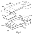
- FIG 8 shows a schematic perspective view of such a handset 900.
- the handset 900 has a battery compartment 902 for holding a removable battery pack 904.
- the removable battery pack 904 is, for example, a rechargeable battery pack.
- the battery pack 904 has terminals (not shown) which connect to corresponding battery connectors 906 of the handset 900 within the battery compartment 902 when the battery pack 904 is installed in the battery compartment.
- the handset 900 also has a power connector 908 at a bottom end 910 thereof.
- a replacement cover portion 950 is adapted to be fitted to the handset 900.
- the replacement cover portion in this embodiment is a rear cover portion and covers the battery compartment 902 of the handset 900 as well as other parts thereof.
- the cover portion 950 has on its inner face or incorporated within it a power-receiving element 952.
- the element 952 may, for example, be the same as the power-receiving element 200 described hereinbefore.
- the cover portion 950 is designed to extend at one end 954 beyond the bottom end 910 of the handset 900. At the end 954 the cover portion 950 has a power connector part 956 carrying one or more power connectors 958.
- the power connector(s) is/are connected in some suitable way (not shown) to the power-receiving element 952, either directly or via power conditioning circuitry such as the circuitry 450 of Figure 4 .
- the power connector(s) 958 is/are adapted to connect to the corresponding power connector(s) of the handset power connector 908.
- This arrangement is convenient in that installation of the cover portion 950 on the handset 900 automatically makes the required electrical connections between the power-receiving element 952 and the power connector 908 of the handset.
- the power connector part 956 of the cover portion 950 may be connected semi-rigidly (e.g. resiliently) instead of rigidly to the remaining parts of the cover portion 950. This can make it easier for the power connector(s) 958 of the cover portion to be connected to the corresponding power connector(s) of the handset 900 when the cover portion is being fitted to the handset.
- FIG 9 shows another embodiment in which the power-receiving element is carried by or incorporated in a replacement cover portion.
- a replacement cover portion 1000 does not have the extended end 954 or the power connector part 956 of the replacement cover portion 950 of Figure 8 .
- an internal power connector part 1002 is connected, preferably via power conditioning circuitry such as the circuitry 450 of Figure 4 , to the power-receiving element 952.
- the connection may be made using flexible wiring 1004.
- the power connector part 1002 is sufficiently thin to enable it to be interposed between the battery terminals of the battery pack 904 and the power connectors 906 formed within the battery compartment 902 of the handset 900.
- the power connector part 1002 has a set of contacts on both its main faces.
- the two sets of contacts are connected together by a pass-through connection arrangement. This enables the power from the battery pack 904 to be supplied to the power connectors 906 when the power-receiving element is not receiving power wirelessly from a transmitter.
- FIG 10 shows yet another embodiment in which a replacement cover portion 1050 carries or incorporates a rechargeable battery pack 1054 in addition to a power-receiving element 952.
- the electrical connections between the power receiving element 952 and the battery pack 1054 are made by suitable means (not shown) incorporated in or carried by the cover portion 1050.
- the fitting of the replacement cover portion 1050 to the handset 900 brings the battery terminals of the battery pack 1054 into contact with the power connectors 906 of the handset 900.
- the present application is a divisional application divided from EP03786118.4 (the "parent" application), which originated as PCT/GB2003/005470 .
- the wording of the original parent claims is provided here as the following set of statements. The applicant reserves the right to rely on this disclosure in the present application and in any divisional application divided from this application.
Abstract
Wireless power receiving apparatus (150) is retrofitted to a portable electrical device (100) to enable the device to receive power wirelessly. The apparatus (150) comprises a power-receiving element (200) adapted to be attached to the device (100), e.g. by adhesive (201), and also being adapted to receive power wirelessly from a transmitter of power when the element and transmitter are in proximity with one another. One or more power connectors (203) are connected electrically to the power-receiving element (200) and are adapted to be connected, when the apparatus (150) is in use, to one or more corresponding power connectors (101) of the portable electrical device (100) to deliver power received by the element (200) to the device (100). The power-receiving element (200) may be in the form of a sticker or may be carried by or incorporated in a replacement cover portion for the portable electrical device (100).
Description
- The present invention relates to adapting portable electrical devices to receive power wirelessly.
- Many of today's portable devices contain an internal secondary cell or battery which may be recharged by temporarily attaching an external adaptor to the power connector of the device. However this is something of a nuisance for users because it requires manual dexterity, requires both hands, and, especially, because different manufacturers use incompatible connectors, so the right adaptor must be located for each device.
- Various means have been proposed for charging devices without the need to attach an external adaptor. These include:
- A surface providing power by presenting an array of contacts which then mate with receiving contacts on the device. Examples include:
- o In academia, the "Networked Surfaces" research conducted by James Scott and Frank Hoffman of the Laboratory for Communications Engineering, Engineering Department, University Of Cambridge, U.K.
- o In business, the wire-free electricity base proposed by Mobile Wise Inc., U.S.A.
- A surface providing power to devices by induction, without any contacts, for example as disclosed in patent publication no.
WO-A-03/96512 - These solutions typically require a device design to be modified, typically by the Original Equipment Manufacturer, in order to incorporate the power-receiving element during manufacture. However there are a very large number of existing portable devices which are not already enabled. It would therefore be convenient to have a solution whereby the user could enable an existing device by simply retrofitting a power-receiving element to it.
- According to a first aspect of the present invention, there is provided wireless power receiving apparatus for use with a portable electrical device to enable the device to receive power wirelessly, the apparatus comprising: a power-receiving element adapted to be attached to the device, and also being adapted to receive power wirelessly from a transmitter of power when the element and transmitter are in proximity with one another; and one or more power connectors which, when the apparatus is an use, are connected electrically to the power-receiving element and are adapted to be connected to one or more corresponding power connectors of the portable electrical device to deliver power received by the element to the device.
- The benefit of the invention is that it enables users to add wireless power transfer capability to their existing portable devices easily.
- In use, the user simply attaches the power-receiving element to the portable device and then connects the power cormector(s) to the corresponding power connector(s) (power-input) of the portable device, thus enabling the device to receive power without wires from a transmitter of power (e.g. an external charger) for example by way of electromagnetic induction.
- The means of attaching the power-receiving element to the device might be an adhesive, or might be some mechanical means such as a clip. The power receiving element could alternatively snap-fit on the device or slide on to it. The element may be removable or permanently attached once applied.
- Yet another way of attaching the power-receiving element to the portable electrical device is to have a rigid connection between the power-receiving element and at least one of the power connectors. In this case, connection of that power connector or those power connectors to the corresponding power connector(s) on the portable electrical device serves to attach the power-receiving element mechanically to the device without the need for any separate attaching means such as adhesive or a clip.
- Another way of attaching the power-receiving element to the portable electrical device is to form the power-receiving element as part of a replacement cover portion of the portable electrical device. Some devices, such as mobile phones, have replaceable cover portions so that the user can change the appearance or "skin" of the device.
- Optionally, the power-connector(s) may be attached to the power-receiving element by a flexible connecting member, allowing the power-connector(s) to be inserted and removed from the device's power-input while the power-receiving element remains attached for convenient future use. Preferably, the flexible connecting member also serves to connect the one or more power connectors electrically to the power-receiving element.
- In one embodiment the electrical connections (e.g. wires) extending between the power-receiving element and power connectors are detachable from the power-receiving element and/or from the power connectors when the apparatus is not in use. This can enable the electrical connections and the power connectors to be removed to protect them from possible damage whilst still leaving the power-receiving element attached.
- By having the electrical connections detachable it is also possible to offer a single design of power-receiving element but several different designs of power connector (or power connector plus electrical connection such as a flying lead) for use with different portable electrical devices.
- Optionally, the power-connector may itself incorporate a contact means similar to the power-receiving input of the device, so that even when it is connected to the device, the device may still be plugged in to a conventional adaptor in a "pass-through" fashion.
- The portable electrical device may have first connector means adapted to connect to corresponding second connector means of external equipment. The first connector means provide the one or more corresponding power connectors of the portable electrical device, possibly together with one or more further connectors for other purposes such as signal or data input/output. In this case, the apparatus preferably further comprises: third connector means adapted to connect to the device's first connector means, the third connector means providing the power connector(s) of the apparatus; fourth connector means adapted to connect to the external equipment's second connector means; and a pass-through connection arrangement interconnecting at least one connector of the third connector means and a corresponding connector of said fourth connector means.
- The third and fourth connector means may be on opposite faces of a power connector unit or block so that the unit or block can be sandwiched between the external equipment (e.g. a car hands-free cradle for a mobile phone) and the portable electrical device. It is not necessary for the pass-through connection arrangement to interconnect the power connectors of the third and fourth connector means, although this is preferable to enable power to be supplied from the external equipment when available. The pass-through connection arrangement could serve just to interconnect signal or data connectors of the third and fourth connector means.
- If the power received by the power-receiving means must be power-conditioned before being passed to the device, the power-conditioning circuitry may optionally be incorporated into the power-receiving element or the power-connector.
- Optionally, all parts of the invention, especially the adhesive, may be substantially waterproof
- Optionally, the power-receiving element may be coloured and textured such that, when adhered to the device, it appears to be a part of the device. Alternatively, or additionally, the power-receiving means may carry text or pictures, for example a logo or advertising.
- Optionally, the power-receiving element may include a substantially transparent pocket into which pictures and the like may be slid.
- In another embodiment, a part of the power-receiving element which must be placed in proximity with the transmitter is marked or coloured or labelled distinctively. In this way, the user can be informed of how to position or orient the power-receiving element (attached to the portable electrical device) relative to the transmitter so that power is transferred efficiently from the transmitter to the power-receiving element.
- Optionally, a power indicator may be provided, optionally in the power-receiving element or the power-connector, to indicate when power is being received and/or being passed to the device. The indicator may produce light (perhaps an LED or electroluminescent panel), sound or vibration.
- Optionally, the power-receiving element may be applied inside the device instead of outside, for example to the rear of the battery compartment.
- Optionally, the power-connector may connect to internal power contacts within the device, possibly to its batteries and/or battery contacts.
- Preferably, the power-receiving element is substantially flat. Alternatively, but preferably in addition, the power-receiving element is flexible. These features make it easy to attach the power-receiving element to the portable electrical device at a suitable internal or external surface portion thereof. When the surface portion is an internal one, having the power-receiving element substantially flat and/or flexible makes it possible to fit the element conveniently even in confined spaces such as battery compartments. When the surface portion is external, these features make it possible to attach the power-receiving element without significantly affecting the overall shape and/or ergonomics of the portable electrical device.
- According to a second aspect of the present invention, there is provided in combination a portable electrical device and wireless power receiving apparatus embodying the aforesaid first aspect of the present invention.
- The following non-exhaustive list illustrates some examples of devices that can be enabled using the present invention. Possibilities are not limited to those described below:
- A mobile communication device, for example a radio, mobile telephone or walkie-talkie;
- A portable computing device, for example a personal digital assistant or palmtop or laptop computer;
- Portable entertainment devices, for example a music player, game console or toy;
- Personal care items, for example a toothbrush, shaver, hair curler, hair rollers;
- A portable imaging device, for example video recorder or camera;
- Containers of contents that may require heating, for example coffee mugs, plates, cooking pots, nail-polish and cosmetic containers;
- Consumer devices, for example torches, clocks and fans;
- A battery-pack for insertion into any of the above;
- A standard-sized battery cell;
- In the case of unintelligent secondary devices such as a battery cell, some sophisticated charge-control means may also be necessary to meter inductive power to the cell and to deal with situations where multiple cells in a device have different charge states. Furthermore, it becomes more important for the transmitter of power to be able to indicate a "charged" condition, since the secondary cell or battery may not be easily visible when located inside another electrical device.
- According to a third aspect of the present invention there is provided a power-receiving element in the form of a sticker adapted to be attached adhesively to a surface portion of a portable electrical device, the element being adapted to receive power wirelessly from a transmitter of power when the element and transmitter are in proximity with one another, and having connection means from which an electrical connection can be made to a power connector of the device.
- By providing the power-receiving element in the form of a sticker the user can readily retrofit the power-receiving element to the portable electrical device.
- For convenience of delivery and attachment, the sticker preferably has a removable backing sheet on its adhesive side which is removed at the time of attaching the element to the device.
- The side of the sticker opposite its adhesive side may conform in appearance to surface portions of the portable electrical device that will be adjacent to that opposite side when the sticker is attached to the device. This can enable the sticker-form power-receiving element to be attached unobtrusively or invisibly to the outside of the portable electrical device.
- In another embodiment the sticker has, on its side opposite its adhesive side, a substantially transparent pocket for carrying an insert. The insert may carry text or pictures, for example a logo or advertising.
- According to a fourth aspect of the present invention, there is provided a replacement cover portion for a portable electrical device, the cover portion carrying or incorporating a power-receiving element adapted to receive power wirelessly from a transmitter of power when the element and transmitter are in proximity with one another, and having connection means from which an electrical connection can be made to a power connector of the device. Preferably, the replacement cover portion has substantially the same size and shape as the cover portion which it replaces. Alternatively, the replacement cover portion may be thicker than that which it replaces, or extend over the side of the portable electrical device which houses the power connector, to allow the connection means to connect to the power connector.
- In one embodiment the replacement cover portion has a power connector part carrying one or more power connectors arranged to connect, when the replacement cover portion is in place on the device, to one or more corresponding power connectors of the portable electrical device. Preferably, the power connector part is connected rigidly or semi-rigidly (e.g. resiliently) to the remaining parts of the replacement cover portion so that fitting the replacement cover portion automatically brings the one or more power connectors of the replacement cover portion into electrical connection with the one or more corresponding power connectors of the portable electrical device.
- In another embodiment, the replacement cover portion covers a battery compartment of the portable electrical device and has one or more battery connectors adapted to connect to one or more corresponding battery connectors of the device and/or to terminals of one or more batteries installed in the device. For example, the one or more battery connectors of the cover portion may be adapted to be interposed between the battery terminals and the corresponding battery connectors of the device.
- In another embodiment, the replacement cover portion covers a battery compartment of the portable electrical device, and the cover portion further carries or incorporates at least one rechargeable battery. When the replacement cover portion is in place on the device the battery is installed operatively in the battery compartment. The power-receiving element is connected operatively to the battery for charging the battery when power is received wirelessly from the transmitter.
- The replacement cover portion is, for example, a replacement cover portion for a handset of a mobile communications network.
- According to a fifth aspect of the present invention, there is provided a method of adapting a portable electrical device having no wireless power receiving capability to have such a capability, the method comprising: attaching a power-receiving element to the device, the element being adapted to receive power wirelessly from a transmitter of power when the element and transmitter are in proximity with one another; and connecting one or more power connectors, which are connected electrically to the element, to one or more corresponding power connectors of the device so that power received by the element can be delivered to the device.
- According to a still further aspect of the present invention, there is provided an attachable means for receiving power, the means comprising:
- i) a substantially flat power-receiving means of sufficiently small dimensions that it can attach to an existing portable device without significantly altering its ergonomics;
- ii) a power connector capable of attaching to the power input of an existing portable device; and
- iii) a means of attaching part or all of the above to a portable device.
- For a better understanding of the present invention and to show how it may be carried into effect, reference will now be made, by way of example only, to the accompanying drawings, in which:
-
Figure 1a shows a schematic side view of a portable electrical device and a first example of wireless power receiving apparatus embodying the present invention; -
Figure 1b is a schematic end view corresponding toFigure 1a ; -
Figure 1c is a plan view corresponding toFigure 1a ; -
Figures 2a to 2c are respective schematic side, end and plan views of a portable electrical device and a second example of wireless power receiving apparatus embodying the present invention; -
Figures 3 a and 3b are respective schematic plan and side views of a power-receiving element embodying the present invention; -
Figure 4 shows a circuit diagram of parts of circuitry included in apparatus according to one embodiment of the present invention; -
Figure 5 shows a schematic cross-sectional view of a power connector of apparatus according to one embodiment of the present invention; -
Figure 6 shows a schematic perspective view of a power-receiving element in the form of a sticker according to one embodiment of the present invention; -
Figure 7 shows a schematic perspective view of a power-receiving element according to another embodiment of the present invention. -
Figure 8 shows a schematic perspective view of parts of a handset for use in a mobile communications network, a battery pack therefor and a replacement cover portion for the handset according to one embodiment of the present invention; -
Figure 9 shows a schematic perspective view of the handset and battery pack ofFigure 8 and a replacement cover portion for the handset according to another embodiment of the present invention; and -
Figure 10 shows a schematic perspective view of the handset ofFigure 8 and a replacement cover portion for the handset according to yet another embodiment of the present invention. -
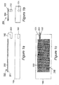
FIGURE 1 shows parts ofapparatus 150 according to a first embodiment of the present invention, and an example portable electrical device (mobile handset) 100 with which the apparatus is used. As originally manufactured the device has no wireless power receiving capability. - As shown in side view in
Figure 1a thedevice 100 has a power-connector 101 which in this case is a socket. Theapparatus 150 comprises a substantially flat power-receivingelement 200, a layer ofadhesive 201, a flexible connecting member (flexible wiring) 202 and a power-connector 203 capable of being plugged-in to the device's power-connector 101. -
Figures 1b and 1 show end and plan views of the arrangement ofFigure 1a . The rear face (underside) of themobile device 100 is uppermost inFigure 1a , and it is to this face that theelement 200 is attached. -
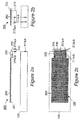
Figures 2a to 2c shows corresponding views to those ofFigures 1a to 1c but forapparatus 160 according to the second embodiment of the present invention. In this case the device power connections (first connector means) 111a,b are contact strips instead of a socket. Thesedevice power connections 111a,b are adapted to connect to corresponding mating strips (second connector means - not shown) of external equipment (not shown) such as a charger. Apower connector unit 213 of the apparatus has corresponding mating strips (third connector means) 215a,b on aninner face 214 thereof which make electrical contact with the device'spower connections 111a,b. In addition, further connectors (fourth connector means) 217a,b are provided on anouter face 216 of thepower connector unit 213 so that other equipment, for example an in-car hands-free unit or charger, having the second connector means may still be connected. Thesefurther connectors 217a,b are connected electrically to the correspondingcontacts 215a,b by a pass-through connection arrangement incorporated into thepower connector unit 213. Theconnectors 215a,b and 217a,b may include connectors used for purposes other than power delivery, for example input/output of signals and data. -
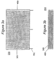
Figures 3a and 3b show plan and side views respectively of one example of a substantially flat power-receivingelement 200 for use in embodiments of the present invention. A magnetic core consists of six strips ofamorphous metal 400 each measuring 50x30x0.02mm, stacked. Around these is wound acoil 300, which could be for example of copper wire, tape, or a stamped or pressed metal. In this case, the coil passes around the core 30 times, with a centre-tap, providing current to threeconnections 202 which connect to further circuitry described later with reference toFigure 4 . The entire element is readily flexible, which is useful in making it conform to any non-flat part of the device to which it is applied, and also makes it less fragile, since the entire element can be less than 0.2mm thick. - Further information regarding the power-receiving element of the example shown in
Figures 3a and 3b , and regarding further examples of suitable power-receiving element is given in our patent publicationsWO-A-03/096361 WO-A-03/096512 -
Figure 4 showscircuitry 450 capable of converting the alternating current delivered by the power receiving element into power suitable for, use in a portable electronic device. A parallel-resonating capacitor 501 tunes the coil, which allows increased power transfer. A value of 100's of nF is typical, depending on the exact core materials and coil construction, and therefore inductance. The alternating current is full-wave rectified bydiodes 500. Schottky diodes with a forward voltage drop of 0.3V provide best performance.Capacitor 502 provides smoothing of the DC. The voltage at this point is unregulated, which may be sufficient to send to subsequent electronics within the portable device, if it is capable of taking such.Optional voltage regulator 503 limits the voltage for devices which are not capable of taking an unregulated supply. This regulator may be a linear or switch mode type, and may optionally also contain other protection and system management circuitry.Optional indicator 504 indicates that power is being received. - An alternative configuration to that shown in
Figures 3a, 3b and4 would be to use a full bridge rectifier instead ofdiodes 500, removing the need for the centre-tap, but increasing the total power loss. With this configuration, the tuning capacitor may be parallel-resonant or series-resonant. -
Figure 5 shows a detail view of one implementation of apower connector 600. A barrel-shaped protrusion carries two conductingrings circuitry 450 ofFigure 4 is contained within the power connector, and theoptional power indicator 504 is visible externally. Optionally theconnector 600 is removable from anend 603 of theflexible wiring 202, allowing different power connectors to be fitted to suit the particular device, each with the appropriate circuitry (power electronics) 450. - Alternatively, one end of the
flexible wiring 202 could be removable from the power-receivingelement 200 and the other end attached permanently to thepower connector 600. This would allow thepower connector 600 andflexible wiring 202 to be sold as one unit, and the power-receiving element to be sold as another unit. Again, this would make it possible to offer different versions of the power connector plus flexible wiring to work with different portable electrical devices, whilst offering only a single design of power-receiving element. The removable connections between the flexible wiring and the power connector and/or power-receiving element can be made by any suitable electrical connection arrangement such as a plug and socket. - A preferred implementation of the present invention is illustrated schematically in
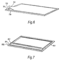
Figure 6 . In this implementation, the power-receiving element is in the form of a "sticker" 700. Theelement 700 has a layer of adhesive 702 on onesurface 701 thereof. The element is supplied with aremovable backing sheet 703 which protects the adhesive 702 prior to attachment of the element to the portable electrical device. Thebacking sheet 703 is peeled off by a user to expose the layer of adhesive 702 onsurface 701. After peeling off thebacking sheet 703 the user simply presses the power-receiving element on itsadhesive side 702 to the portable electrical device. -
Figure 7 shows a schematic perspective view of a power-receiving element in another embodiment of the present invention. In this embodiment the power-receivingelement 800 has, on itsside 801 which will be visible to a user when the element is attached to the device, atransparent pocket 802. Aninsert 803, for example a slip of paper or card, is earned within thepocket 802. The insert may bear text or pictures, for example a logo or advertising. - Another preferred implementation of apparatus embodying the present invention is in the form of a replacement cover portion of the portable electrical device itself. There are several types of portable electrical device commercially available which have replaceable cover portions. Handsets for use in mobile communications networks made by several major manufacturers are one example. Replacement cover portions for such devices can advantageously carry or incorporate at least the power-receiving element of apparatus embodying the present invention.
-
Figure 8 shows a schematic perspective view of such ahandset 900. Thehandset 900 has abattery compartment 902 for holding aremovable battery pack 904. Theremovable battery pack 904 is, for example, a rechargeable battery pack. Thebattery pack 904 has terminals (not shown) which connect tocorresponding battery connectors 906 of thehandset 900 within thebattery compartment 902 when thebattery pack 904 is installed in the battery compartment. Thehandset 900 also has apower connector 908 at abottom end 910 thereof. - A
replacement cover portion 950 according to an embodiment of the present invention is adapted to be fitted to thehandset 900. The replacement cover portion in this embodiment is a rear cover portion and covers thebattery compartment 902 of thehandset 900 as well as other parts thereof. Thecover portion 950 has on its inner face or incorporated within it a power-receivingelement 952. Theelement 952 may, for example, be the same as the power-receivingelement 200 described hereinbefore. Thecover portion 950 is designed to extend at oneend 954 beyond thebottom end 910 of thehandset 900. At theend 954 thecover portion 950 has apower connector part 956 carrying one ormore power connectors 958. The power connector(s) is/are connected in some suitable way (not shown) to the power-receivingelement 952, either directly or via power conditioning circuitry such as thecircuitry 450 ofFigure 4 . The power connector(s) 958 is/are adapted to connect to the corresponding power connector(s) of thehandset power connector 908. This arrangement is convenient in that installation of thecover portion 950 on thehandset 900 automatically makes the required electrical connections between the power-receivingelement 952 and thepower connector 908 of the handset. If necessary, thepower connector part 956 of thecover portion 950 may be connected semi-rigidly (e.g. resiliently) instead of rigidly to the remaining parts of thecover portion 950. This can make it easier for the power connector(s) 958 of the cover portion to be connected to the corresponding power connector(s) of thehandset 900 when the cover portion is being fitted to the handset. -
Figure 9 shows another embodiment in which the power-receiving element is carried by or incorporated in a replacement cover portion. InFigure 9 , areplacement cover portion 1000 does not have theextended end 954 or thepower connector part 956 of thereplacement cover portion 950 ofFigure 8 . Instead, an internalpower connector part 1002 is connected, preferably via power conditioning circuitry such as thecircuitry 450 ofFigure 4 , to the power-receivingelement 952. The connection may be made usingflexible wiring 1004. Thepower connector part 1002 is sufficiently thin to enable it to be interposed between the battery terminals of thebattery pack 904 and thepower connectors 906 formed within thebattery compartment 902 of thehandset 900. In a similar way to that described previously with reference toFigure 2 , thepower connector part 1002 has a set of contacts on both its main faces. The two sets of contacts are connected together by a pass-through connection arrangement. This enables the power from thebattery pack 904 to be supplied to thepower connectors 906 when the power-receiving element is not receiving power wirelessly from a transmitter. -
Figure 10 shows yet another embodiment in which areplacement cover portion 1050 carries or incorporates a rechargeable battery pack 1054 in addition to a power-receivingelement 952. The electrical connections between thepower receiving element 952 and the battery pack 1054 are made by suitable means (not shown) incorporated in or carried by thecover portion 1050. The fitting of thereplacement cover portion 1050 to thehandset 900 brings the battery terminals of the battery pack 1054 into contact with thepower connectors 906 of thehandset 900. - The preferred features of the invention are applicable to all aspects of the invention and may be used in any possible combination.
- Throughout the description and claims of this specification, the words "comprise" and "contain" and variations of the words, for example "comprising" and "comprises", mean "including but not limited to", and are not intended to (and do not) exclude other components, integers, moieties, additives or steps.
- The present application is a divisional application divided from
EP03786118.4 PCT/GB2003/005470 - A1. Wireless power receiving apparatus for use with a portable electrical device to enable the device to receive power wirelessly, the apparatus comprising:
- a power-receiving element adapted to be attached to the device, and also being adapted to receive power wirelessly from a transmitter of power when the element and transmitter are in proximity with one another; and
- one or more power connectors which, when the apparatus is in use, are connected electrically to the power-receiving element and are adapted to be connected to one or more corresponding power connectors of the portable electrical device to deliver power received by the element to the device.
- A2. Apparatus according to statement A1, wherein said power-receiving element is adapted to be attached adhesively to the device when the apparatus is in use.
- A3. Apparatus according to statement A1, further comprising mechanical attachment means adapted to attach the power-receiving element mechanically to the device when the apparatus is in use.
- A4. Apparatus according to statement A1, wherein said power-receiving element forms part of a replacement cover portion of the portable electrical device.
- A5. Apparatus according to statement A1, wherein said power-receiving element and at least one of said power connectors of the apparatus are connected rigidly together, whereby connection of said at least one power connector to its said corresponding power connector of the portable electrical device serves to attach the power-receiving element mechanically to the device.
- A6. Apparatus according to any one of statements A1 to A4, further comprising a flexible connecting member connecting said one or more power connectors flexibly to said power-receiving element.
- A7. Apparatus according to statement A6, wherein said flexible connecting member also serves to connect said one or more power connectors electrically to the power-receiving element.
- A8. Apparatus according to any one of statements A1 to A5, having one or more electrical connections extending between said power-receiving element and said one or more power connectors, said one or more electrical connections being detachable from said power-receiving element and/or from said one or more power connectors when the apparatus is not in use.
- A9. Apparatus according to any preceding statement, wherein said portable electrical device has first connector means adapted to connect to corresponding second connector means of external equipment, said first connector means providing said one or more corresponding power connectors of the portable electrical device, and the apparatus further comprising:
- third connector means adapted to connect to said first connector means of the portable electrical device, said third connector means providing said one or more power connectors of the apparatus;
- fourth connector means adapted to connect to said second connector means of said external equipment; and
- a pass-through connection arrangement interconnecting at least one connector of said third connector means and a corresponding connector of said fourth connector means.
- A10. Apparatus according to statement A9, wherein said first to fourth connector means also provide connectors for purposes other than power delivery, and said pass-through connection arrangement serves to interconnect corresponding connectors of said third and fourth connector means used for said other purposes.
- A11. Apparatus according to any preceding statement, further comprising:
- power-conditioning circuitry operable to condition the power received by the power-receiving element prior to delivery to the portable electrical device.
- A 12. Apparatus according to any preceding statement, wherein said power-receiving element is small relative to said portable electrical device.
- A13. Apparatus according to any preceding statement, wherein said power-receiving element is thin relative to said portable electrical device.
- A 14. Apparatus according to any preceding statement, wherein a volume occupied by said power-receiving element is small in comparison with a volume occupied by said portable electrical device.
- A15. Apparatus according to any preceding statement, wherein said power-receiving element is of sufficiently small dimensions that, when attached to the portable electrical device, it does not substantially alter the ergonomics of the device.
- A16. Apparatus according to any preceding statement, wherein parts of said power-receiving element that are visible to a user of the device when the element is attached to the device have an external appearance which conforms to an external appearance of adjacent parts of the device.
- A17. Apparatus according to any preceding statement, wherein a part of said power-receiving element which must be placed in proximity with the transmitter is marked or coloured or labelled distinctively.
- A18. Apparatus according to any preceding statement, wherein said power-receiving element has, at a surface thereof that is visible to a user of the portable electrical device when the element is attached to the device, a substantially transparent pocket for carrying an insert to be visible to the user.
- A19. Apparatus according to any preceding statement further comprising an indicator which produces a predetermined indication of an operating state of the apparatus.
- A20. Apparatus according to any preceding statement, wherein said power-receiving element is substantially flat.
- A21. Apparatus according to any preceding statement, wherein said power-receiving element is flexible.
- A22. In combination a portable electrical device and wireless power receiving apparatus according to any preceding statement.
- A23. The combination of statement A22, wherein said power-receiving element is attached to an external surface portion of the device.
- A24. The combination of statement A22, wherein said power-receiving element is attached to an internal surface portion of the device.
- A25. The combination of statement A24, wherein said internal surface portion is a surface portion of a battery compartment of the device.
- A26. The combination of any one of statements A22 to A25, wherein said one or more corresponding power connectors of the portable electrical device are internal power connectors.
- A27. The combination of any one of statements A22 to A26, wherein said one or more corresponding power connectors of the portable electrical device are battery connectors.
- A28. A power-receiving element in the form of a sticker adapted to be attached adhesively to a surface portion of a portable electrical device, the element being adapted to receive power wirelessly from a transmitter of power when the element and transmitter are in proximity with one another, and having connection means from which an electrical connection can be made to a power connector of the device.
- A29. A power-receiving element according to statement A28, wherein said sticker has a removable backing sheet on its adhesive side which is removed at the time of attaching the element to the device.
- A30. A power-receiving element according to statement A28 or A29, wherein a side of said sticker opposite its adhesive side conforms in appearance to surface portions of the portable electrical device that will be adjacent to said opposite side when the sticker is attached to the device.
- A31. A power-receiving element according to any one of statements A28 to A30, wherein said sticker has, on its side opposite its adhesive side, a substantially transparent pocket for carrying an insert.
- A32. A replacement cover portion for a portable electrical device, the cover portion carrying or incorporating a power-receiving element adapted to receive power wirelessly from a transmitter of power when the element and transmitter are in proximity with one another, and having connection means from which an electrical connection can be made to a power connector of the device.
- A33. A replacement cover portion according to statement A32, having a power connector part carrying one or more power connectors connected operatively to the power-receiving element and arranged to connect, when the replacement cover portion is in place on the device, to one or more corresponding power connectors of the portable electrical device.
- A34. A replacement cover portion according to statement A32 or A33, adapted to cover a battery compartment of the portable electrical device, and having one or more battery connectors adapted to connect to one or more corresponding battery connectors of the device and/or to terminals of one or more batteries installed in the device.
- A35. A replacement cover portion according to statement A34, wherein said one or more battery connectors of the cover portion are adapted to be interposed between said battery terminals and said corresponding battery connectors of the device.
- A36. A replacement cover portion according to statement A32 or A33, adapted to cover a battery compartment of the portable electrical device, and further carrying or incorporating at least one rechargeable battery such that, when the replacement cover portion is in place on a device, the battery is installed operatively in the battery compartment, the power-receiving element being connected operatively to the battery for charging the battery for charging the battery when power is received wirelessly from the transmitter.
- A37. A replacement cover portion according to any one of statements A32 to A36, being a replacement cover portion for a handset of a mobile communications network.
- A38. A method of adapting a portable electrical device having no wireless power receiving capability to have such a capability, the method comprising:
- attaching a power-receiving element to the device, the element being adapted to receive power wirelessly from a transmitter of power when the element and transmitter are in proximity with one another; and
- connecting one or more power connectors, which are connected electrically to the element, to one or more corresponding power connectors of the device so that power received by the element can be delivered to the device.
Claims (15)
- Inductive power receiving apparatus for use with a portable electrical device to enable said device to receive power wirelessly by electromagnetic induction, said apparatus comprising:an inductive power-receiving element adapted to be attached to said portable electrical device, and also being adapted to receive power wirelessly by electromagnetic induction from a transmitter of power when said inductive power-receiving element and said transmitter are in proximity with one another; andone or more power connectors which, when the apparatus is in use, are connected electrically to the power-receiving element and are adapted to be connected to one or more corresponding power connectors of the portable electrical device to deliver power received by the element to the device, electrical connections extending between the inductive power-receiving element and said one or more power connectors of the inductive power receiving apparatus being detachable from said power-receiving element and/or from said portable electrical device while said power-receiving element is attached to said portable electrical device.
- Apparatus as claimed in claim 1, further comprising mechanical attachment means adapted to attach said power-receiving element mechanically to said device.
- Apparatus as claimed in claim 1, further comprising a flexible connecting member connecting said one or more power connectors of the inductive power receiving apparatus to said inductive power-receiving element, wherein said one or more power connectors of the inductive power receiving apparatus are insertable and removable from said one or more corresponding power connectors of said portable electrical device while said inductive power-receiving element remains attached to said portable electrical device.
- Apparatus as claimed in claim 3, wherein said one or more corresponding power connectors of said portable electrical device includes a power input of said portable electrical device.
- Apparatus as claimed in any preceding claim, wherein said power-receiving element is of sufficiently small dimensions that, when attached to said portable electrical device, it does not substantially alter the ergonomics of said device.
- Apparatus as claimed in any preceding claim, wherein adhesive attaches said inductive power-receiving element to said portable electrical device.
- Apparatus as claimed in any preceding claim, adapted to be retrofitted to a said portable electrical device having no inductive power receiving capability so as to provide said device with that capability.
- In combination a portable electrical device and inductive power receiving apparatus as claimed in any preceding claim.
- A method of adapting a portable electrical device having no inductive power receiving capability to have such a capability, said method comprising:attaching an inductive power-receiving element to said device, said element being adapted to receive power wirelessly by electromagnetic induction from a transmitter of power when said element and transmitter are in proximity with one another; andconnecting one or more power connectors, which are connected electrically to said element, to one or more corresponding power connectors of said device so that power received by said element can be delivered to said device, electrical connections extending between the inductive power-receiving element and said one or more power connectors being detachable from said power-receiving element and/or from said portable electrical device while said power-receiving element is attached to said portable electrical device.
- A method as claimed in claim 9, wherein a flexible connecting member connects said one or more power connectors to said inductive power-receiving element, said one or more power connectors being insertable and removable from said one or more corresponding power connectors of said portable electrical device while said inductive power-receiving element remains attached to said portable electrical device.
- A method as claimed in claim 9 or 10, wherein said one or more corresponding power connectors of said portable electrical device includes a power input of said portable electrical device.
- A method as claimed in any of claims 9 to 11, wherein said power-receiving element is of sufficiently small dimensions that, when attached to said portable electrical device, it does not substantially alter the ergonomics of said device.
- A method as claimed in any of claims 9 to 12, wherein adhesive is used to attach said inductive power-receiving element to said portable electrical device.
- A method as claimed in any of claims 9 to 13, including retro-fitting said portable electrical device having no inductive power receiving capability so as to provide said device with that capability.
- A method as claimed in any of claims 9 to 14, including detaching said one or more power connectors from said portable electrical device whilst leaving said power-receiving element attached to said portable electrical device.
Applications Claiming Priority (2)
| Application Number | Priority Date | Filing Date | Title |
|---|---|---|---|
| GBGB0229141.7A GB0229141D0 (en) | 2002-12-16 | 2002-12-16 | Improvements relating to contact-less power transfer |
| EP03786118.4A EP1573489B1 (en) | 2002-12-16 | 2003-12-16 | Adapting portable electrical devices to receive power wirelessly |
Related Parent Applications (2)
| Application Number | Title | Priority Date | Filing Date |
|---|---|---|---|
| EP03786118.4 Division | 2003-12-16 | ||
| EP03786118.4A Division-Into EP1573489B1 (en) | 2002-12-16 | 2003-12-16 | Adapting portable electrical devices to receive power wirelessly |
Publications (1)
| Publication Number | Publication Date |
|---|---|
| EP2330480A1 true EP2330480A1 (en) | 2011-06-08 |
Family
ID=9949665
Family Applications (5)
| Application Number | Title | Priority Date | Filing Date |
|---|---|---|---|
| EP03786118.4A Expired - Lifetime EP1573489B1 (en) | 2002-12-16 | 2003-12-16 | Adapting portable electrical devices to receive power wirelessly |
| EP10187345A Ceased EP2275897A3 (en) | 2002-12-16 | 2003-12-16 | Adapting portable electrical devices to receive power wirelessly |
| EP10187343.8A Expired - Lifetime EP2275896B1 (en) | 2002-12-16 | 2003-12-16 | Adapting portable electrical devices to receive power wirelessly |
| EP11152593A Withdrawn EP2330480A1 (en) | 2002-12-16 | 2003-12-16 | Adapting portable electrical devices to receive power wirelessly |
| EP10187342A Withdrawn EP2275895A3 (en) | 2002-12-16 | 2003-12-16 | Adapting portable electrical devices to receive power wirelessly |
Family Applications Before (3)
| Application Number | Title | Priority Date | Filing Date |
|---|---|---|---|
| EP03786118.4A Expired - Lifetime EP1573489B1 (en) | 2002-12-16 | 2003-12-16 | Adapting portable electrical devices to receive power wirelessly |
| EP10187345A Ceased EP2275897A3 (en) | 2002-12-16 | 2003-12-16 | Adapting portable electrical devices to receive power wirelessly |
| EP10187343.8A Expired - Lifetime EP2275896B1 (en) | 2002-12-16 | 2003-12-16 | Adapting portable electrical devices to receive power wirelessly |
Family Applications After (1)
| Application Number | Title | Priority Date | Filing Date |
|---|---|---|---|
| EP10187342A Withdrawn EP2275895A3 (en) | 2002-12-16 | 2003-12-16 | Adapting portable electrical devices to receive power wirelessly |
Country Status (8)
| Country | Link |
|---|---|
| US (5) | US8055310B2 (en) |
| EP (5) | EP1573489B1 (en) |
| JP (2) | JP4925393B2 (en) |
| CN (1) | CN100347633C (en) |
| AU (1) | AU2003295117A1 (en) |
| GB (1) | GB0229141D0 (en) |
| HK (1) | HK1088086A1 (en) |
| WO (1) | WO2004055654A2 (en) |
Families Citing this family (268)
| Publication number | Priority date | Publication date | Assignee | Title |
|---|---|---|---|---|
| GB2399466B (en) * | 2003-03-10 | 2005-11-16 | Univ City Hong Kong | Battery charging system |
| US8917057B2 (en) | 2002-06-10 | 2014-12-23 | City University Of Hong Kong | Battery charging system |
| AU2003229145A1 (en) | 2002-06-10 | 2003-12-22 | City University Of Hong Kong | Planar inductive battery charger |
| US7982436B2 (en) * | 2002-12-10 | 2011-07-19 | Pure Energy Solutions, Inc. | Battery cover with contact-type power receiver for electrically powered device |
| US7932638B2 (en) * | 2002-12-10 | 2011-04-26 | Pure Energy Solutions, Inc. | Reliable contact and safe system and method for providing power to an electronic device |
| US20120080958A1 (en) * | 2002-12-10 | 2012-04-05 | Pure Energy Solutions, Inc. | Reliable contact and safe system and method for providing power to an electronic device |
| GB0229141D0 (en) | 2002-12-16 | 2003-01-15 | Splashpower Ltd | Improvements relating to contact-less power transfer |
| US10575376B2 (en) | 2004-02-25 | 2020-02-25 | Lynk Labs, Inc. | AC light emitting diode and AC LED drive methods and apparatus |
| WO2011143510A1 (en) | 2010-05-12 | 2011-11-17 | Lynk Labs, Inc. | Led lighting system |
| US10499465B2 (en) | 2004-02-25 | 2019-12-03 | Lynk Labs, Inc. | High frequency multi-voltage and multi-brightness LED lighting devices and systems and methods of using same |
| EP1782331B1 (en) | 2004-08-16 | 2018-01-31 | Giesecke+Devrient Mobile Security GmbH | User input device including user input evaluation and method |
| US8594567B2 (en) | 2004-08-16 | 2013-11-26 | Giesecke & Devrient Gmbh | Controlled wireless charging of an accumulator in a chipcard |
| US7970870B2 (en) | 2005-06-24 | 2011-06-28 | Microsoft Corporation | Extending digital artifacts through an interactive surface |
| US7825543B2 (en) | 2005-07-12 | 2010-11-02 | Massachusetts Institute Of Technology | Wireless energy transfer |
| AU2006269374C1 (en) | 2005-07-12 | 2010-03-25 | Massachusetts Institute Of Technology | Wireless non-radiative energy transfer |
| US7514899B2 (en) | 2005-11-18 | 2009-04-07 | Avago Technologies Ecbu Ip (Singapore) Pte. Ltd. | Method and apparatus for optical wireless charging |
| GB0524790D0 (en) * | 2005-12-05 | 2006-01-11 | Univ City Hong Kong | Apparatus and method for the charging of electrical devices |
| FR2895164A1 (en) * | 2005-12-19 | 2007-06-22 | France Telecom | ENVELOPE AND CASE FOR RECHARGING AN ELECTRONIC APPARATUS IN MOBILITY SITUATION |
| US8447234B2 (en) | 2006-01-18 | 2013-05-21 | Qualcomm Incorporated | Method and system for powering an electronic device via a wireless link |
| US9130602B2 (en) | 2006-01-18 | 2015-09-08 | Qualcomm Incorporated | Method and apparatus for delivering energy to an electrical or electronic device via a wireless link |
| US8169185B2 (en) | 2006-01-31 | 2012-05-01 | Mojo Mobility, Inc. | System and method for inductive charging of portable devices |
| US11201500B2 (en) | 2006-01-31 | 2021-12-14 | Mojo Mobility, Inc. | Efficiencies and flexibilities in inductive (wireless) charging |
| US7952322B2 (en) * | 2006-01-31 | 2011-05-31 | Mojo Mobility, Inc. | Inductive power source and charging system |
| JP4635918B2 (en) * | 2006-03-13 | 2011-02-23 | ソニー株式会社 | Mobile phone protective cover and mobile phone charging system. |
| MX2008011902A (en) * | 2006-03-22 | 2008-11-06 | Powercast Corp | Method and apparatus for implementation of a wireless power supply. |
| US7948208B2 (en) | 2006-06-01 | 2011-05-24 | Mojo Mobility, Inc. | Power source, charging system, and inductive receiver for mobile devices |
| US11329511B2 (en) | 2006-06-01 | 2022-05-10 | Mojo Mobility Inc. | Power source, charging system, and inductive receiver for mobile devices |
| JP4855150B2 (en) * | 2006-06-09 | 2012-01-18 | 株式会社トプコン | Fundus observation apparatus, ophthalmic image processing apparatus, and ophthalmic image processing program |
| US9129741B2 (en) * | 2006-09-14 | 2015-09-08 | Qualcomm Incorporated | Method and apparatus for wireless power transmission |
| US7706771B2 (en) * | 2007-02-08 | 2010-04-27 | Broadcom Corporation | Inductive powering for a mobile communication device and method for use therewith |
| US8378522B2 (en) | 2007-03-02 | 2013-02-19 | Qualcomm, Incorporated | Maximizing power yield from wireless power magnetic resonators |
| US9774086B2 (en) | 2007-03-02 | 2017-09-26 | Qualcomm Incorporated | Wireless power apparatus and methods |
| US8199117B2 (en) | 2007-05-09 | 2012-06-12 | Microsoft Corporation | Archive for physical and digital objects |
| US8805530B2 (en) | 2007-06-01 | 2014-08-12 | Witricity Corporation | Power generation for implantable devices |
| US9421388B2 (en) | 2007-06-01 | 2016-08-23 | Witricity Corporation | Power generation for implantable devices |
| US9124120B2 (en) | 2007-06-11 | 2015-09-01 | Qualcomm Incorporated | Wireless power system and proximity effects |
| TW200901599A (en) * | 2007-06-29 | 2009-01-01 | rong-cong Lin | Battery cover |
| KR20100057632A (en) | 2007-08-09 | 2010-05-31 | 퀄컴 인코포레이티드 | Increasing the q factor of a resonator |
| US20090072628A1 (en) * | 2007-09-13 | 2009-03-19 | Nigel Power, Llc | Antennas for Wireless Power applications |
| WO2009039113A1 (en) * | 2007-09-17 | 2009-03-26 | Nigel Power, Llc | Transmitters and receivers for wireless energy transfer |
| FI120853B (en) * | 2007-09-18 | 2010-03-31 | Powerkiss Oy | Energy transfer device and method |
| US11317495B2 (en) | 2007-10-06 | 2022-04-26 | Lynk Labs, Inc. | LED circuits and assemblies |
| US11297705B2 (en) | 2007-10-06 | 2022-04-05 | Lynk Labs, Inc. | Multi-voltage and multi-brightness LED lighting devices and methods of using same |
| KR101414404B1 (en) | 2007-10-11 | 2014-07-01 | 퀄컴 인코포레이티드 | Wireless power transfer using magneto mechanical systems |
| RU2493579C2 (en) * | 2007-10-17 | 2013-09-20 | Эксесс Бизнес Груп Интернейшнл Ллс | Wireless systems for electrical powering of portable computers and electronic devices |
| US7986059B2 (en) * | 2008-01-04 | 2011-07-26 | Pure Energy Solutions, Inc. | Device cover with embedded power receiver |
| AU2009204263A1 (en) | 2008-01-07 | 2009-07-16 | Access Business Group International Llc | Wireless power adapter for computer |
| US8367235B2 (en) * | 2008-01-18 | 2013-02-05 | Mophie, Inc. | Battery pack, holster, and extendible processing and interface platform for mobile devices |
| DE102008007822A1 (en) * | 2008-02-07 | 2009-08-13 | Fraunhofer-Gesellschaft zur Förderung der angewandten Forschung e.V. | Wireless charging interface for an energy storage |
| WO2009142795A1 (en) * | 2008-03-03 | 2009-11-26 | Mitch Randall | Apparatus and method for retrofitting a broad range of mobile devices to receive wireless power |
| US20100022285A1 (en) * | 2008-03-03 | 2010-01-28 | Wildcharge, Inc. | Apparatus and method for retrofitting a broad range of mobile devices to receive wireless power |
| US8629576B2 (en) | 2008-03-28 | 2014-01-14 | Qualcomm Incorporated | Tuning and gain control in electro-magnetic power systems |
| US20110050164A1 (en) | 2008-05-07 | 2011-03-03 | Afshin Partovi | System and methods for inductive charging, and improvements and uses thereof |
| US8878393B2 (en) | 2008-05-13 | 2014-11-04 | Qualcomm Incorporated | Wireless power transfer for vehicles |
| US20090284369A1 (en) | 2008-05-13 | 2009-11-19 | Qualcomm Incorporated | Transmit power control for a wireless charging system |
| CA2724341C (en) | 2008-05-14 | 2016-07-05 | Massachusetts Institute Of Technology | Wireless energy transfer, including interference enhancement |
| US7855529B2 (en) * | 2008-07-16 | 2010-12-21 | ConvenientPower HK Ltd. | Inductively powered sleeve for mobile electronic device |
| US8723366B2 (en) | 2008-09-27 | 2014-05-13 | Witricity Corporation | Wireless energy transfer resonator enclosures |
| US8963488B2 (en) | 2008-09-27 | 2015-02-24 | Witricity Corporation | Position insensitive wireless charging |
| US9160203B2 (en) | 2008-09-27 | 2015-10-13 | Witricity Corporation | Wireless powered television |
| US9184595B2 (en) | 2008-09-27 | 2015-11-10 | Witricity Corporation | Wireless energy transfer in lossy environments |
| US8901779B2 (en) | 2008-09-27 | 2014-12-02 | Witricity Corporation | Wireless energy transfer with resonator arrays for medical applications |
| US9105959B2 (en) | 2008-09-27 | 2015-08-11 | Witricity Corporation | Resonator enclosure |
| US9544683B2 (en) | 2008-09-27 | 2017-01-10 | Witricity Corporation | Wirelessly powered audio devices |
| US8598743B2 (en) | 2008-09-27 | 2013-12-03 | Witricity Corporation | Resonator arrays for wireless energy transfer |
| US9601261B2 (en) | 2008-09-27 | 2017-03-21 | Witricity Corporation | Wireless energy transfer using repeater resonators |
| US8957549B2 (en) | 2008-09-27 | 2015-02-17 | Witricity Corporation | Tunable wireless energy transfer for in-vehicle applications |
| US8466583B2 (en) | 2008-09-27 | 2013-06-18 | Witricity Corporation | Tunable wireless energy transfer for outdoor lighting applications |
| US8587153B2 (en) | 2008-09-27 | 2013-11-19 | Witricity Corporation | Wireless energy transfer using high Q resonators for lighting applications |
| US8487480B1 (en) | 2008-09-27 | 2013-07-16 | Witricity Corporation | Wireless energy transfer resonator kit |
| US8669676B2 (en) | 2008-09-27 | 2014-03-11 | Witricity Corporation | Wireless energy transfer across variable distances using field shaping with magnetic materials to improve the coupling factor |
| US8692412B2 (en) | 2008-09-27 | 2014-04-08 | Witricity Corporation | Temperature compensation in a wireless transfer system |
| US8461722B2 (en) | 2008-09-27 | 2013-06-11 | Witricity Corporation | Wireless energy transfer using conducting surfaces to shape field and improve K |
| US8552592B2 (en) | 2008-09-27 | 2013-10-08 | Witricity Corporation | Wireless energy transfer with feedback control for lighting applications |
| US9246336B2 (en) | 2008-09-27 | 2016-01-26 | Witricity Corporation | Resonator optimizations for wireless energy transfer |
| US8933594B2 (en) | 2008-09-27 | 2015-01-13 | Witricity Corporation | Wireless energy transfer for vehicles |
| US9601266B2 (en) | 2008-09-27 | 2017-03-21 | Witricity Corporation | Multiple connected resonators with a single electronic circuit |
| US8643326B2 (en) | 2008-09-27 | 2014-02-04 | Witricity Corporation | Tunable wireless energy transfer systems |
| US9515494B2 (en) | 2008-09-27 | 2016-12-06 | Witricity Corporation | Wireless power system including impedance matching network |
| US8410636B2 (en) | 2008-09-27 | 2013-04-02 | Witricity Corporation | Low AC resistance conductor designs |
| US9744858B2 (en) | 2008-09-27 | 2017-08-29 | Witricity Corporation | System for wireless energy distribution in a vehicle |
| US8471410B2 (en) | 2008-09-27 | 2013-06-25 | Witricity Corporation | Wireless energy transfer over distance using field shaping to improve the coupling factor |
| US8901778B2 (en) | 2008-09-27 | 2014-12-02 | Witricity Corporation | Wireless energy transfer with variable size resonators for implanted medical devices |
| US8772973B2 (en) | 2008-09-27 | 2014-07-08 | Witricity Corporation | Integrated resonator-shield structures |
| US9035499B2 (en) | 2008-09-27 | 2015-05-19 | Witricity Corporation | Wireless energy transfer for photovoltaic panels |
| US9318922B2 (en) | 2008-09-27 | 2016-04-19 | Witricity Corporation | Mechanically removable wireless power vehicle seat assembly |
| US8476788B2 (en) | 2008-09-27 | 2013-07-02 | Witricity Corporation | Wireless energy transfer with high-Q resonators using field shaping to improve K |
| US8587155B2 (en) | 2008-09-27 | 2013-11-19 | Witricity Corporation | Wireless energy transfer using repeater resonators |
| US8907531B2 (en) | 2008-09-27 | 2014-12-09 | Witricity Corporation | Wireless energy transfer with variable size resonators for medical applications |
| US9106203B2 (en) | 2008-09-27 | 2015-08-11 | Witricity Corporation | Secure wireless energy transfer in medical applications |
| US8461721B2 (en) | 2008-09-27 | 2013-06-11 | Witricity Corporation | Wireless energy transfer using object positioning for low loss |
| US9093853B2 (en) | 2008-09-27 | 2015-07-28 | Witricity Corporation | Flexible resonator attachment |
| US9065423B2 (en) | 2008-09-27 | 2015-06-23 | Witricity Corporation | Wireless energy distribution system |
| US8400017B2 (en) | 2008-09-27 | 2013-03-19 | Witricity Corporation | Wireless energy transfer for computer peripheral applications |
| US9577436B2 (en) | 2008-09-27 | 2017-02-21 | Witricity Corporation | Wireless energy transfer for implantable devices |
| US9601270B2 (en) | 2008-09-27 | 2017-03-21 | Witricity Corporation | Low AC resistance conductor designs |
| US8946938B2 (en) | 2008-09-27 | 2015-02-03 | Witricity Corporation | Safety systems for wireless energy transfer in vehicle applications |
| US8461720B2 (en) | 2008-09-27 | 2013-06-11 | Witricity Corporation | Wireless energy transfer using conducting surfaces to shape fields and reduce loss |
| US8922066B2 (en) | 2008-09-27 | 2014-12-30 | Witricity Corporation | Wireless energy transfer with multi resonator arrays for vehicle applications |
| CN107415706B (en) | 2008-09-27 | 2020-06-09 | 韦特里西提公司 | Wireless energy transfer system |
| US8686598B2 (en) | 2008-09-27 | 2014-04-01 | Witricity Corporation | Wireless energy transfer for supplying power and heat to a device |
| US8692410B2 (en) | 2008-09-27 | 2014-04-08 | Witricity Corporation | Wireless energy transfer with frequency hopping |
| US8497601B2 (en) | 2008-09-27 | 2013-07-30 | Witricity Corporation | Wireless energy transfer converters |
| US8947186B2 (en) | 2008-09-27 | 2015-02-03 | Witricity Corporation | Wireless energy transfer resonator thermal management |
| US8912687B2 (en) | 2008-09-27 | 2014-12-16 | Witricity Corporation | Secure wireless energy transfer for vehicle applications |
| US8304935B2 (en) | 2008-09-27 | 2012-11-06 | Witricity Corporation | Wireless energy transfer using field shaping to reduce loss |
| US8482158B2 (en) | 2008-09-27 | 2013-07-09 | Witricity Corporation | Wireless energy transfer using variable size resonators and system monitoring |
| US8324759B2 (en) | 2008-09-27 | 2012-12-04 | Witricity Corporation | Wireless energy transfer using magnetic materials to shape field and reduce loss |
| US8441154B2 (en) | 2008-09-27 | 2013-05-14 | Witricity Corporation | Multi-resonator wireless energy transfer for exterior lighting |
| US8569914B2 (en) | 2008-09-27 | 2013-10-29 | Witricity Corporation | Wireless energy transfer using object positioning for improved k |
| US8937408B2 (en) | 2008-09-27 | 2015-01-20 | Witricity Corporation | Wireless energy transfer for medical applications |
| US9396867B2 (en) | 2008-09-27 | 2016-07-19 | Witricity Corporation | Integrated resonator-shield structures |
| US8629578B2 (en) | 2008-09-27 | 2014-01-14 | Witricity Corporation | Wireless energy transfer systems |
| US8928276B2 (en) | 2008-09-27 | 2015-01-06 | Witricity Corporation | Integrated repeaters for cell phone applications |
| US8362651B2 (en) | 2008-10-01 | 2013-01-29 | Massachusetts Institute Of Technology | Efficient near-field wireless energy transfer using adiabatic system variations |
| US8810194B2 (en) | 2008-11-20 | 2014-08-19 | Qualcomm Incorporated | Retrofitting wireless power and near-field communication in electronic devices |
| JP5141518B2 (en) * | 2008-11-28 | 2013-02-13 | 富士通株式会社 | Mobile terminal device |
| EP2377296B1 (en) * | 2009-01-05 | 2019-10-16 | QUALCOMM Incorporated | Interior connector scheme for accessorizing a mobile computing device with a removeable housing segment |
| JP5628191B2 (en) * | 2009-02-05 | 2014-11-19 | クゥアルコム・インコーポレイテッドQualcomm Incorporated | Retrofitting wireless power and near field communication in electronic devices |
| US8854224B2 (en) | 2009-02-10 | 2014-10-07 | Qualcomm Incorporated | Conveying device information relating to wireless charging |
| US9312924B2 (en) | 2009-02-10 | 2016-04-12 | Qualcomm Incorporated | Systems and methods relating to multi-dimensional wireless charging |
| US20100201312A1 (en) | 2009-02-10 | 2010-08-12 | Qualcomm Incorporated | Wireless power transfer for portable enclosures |
| KR101083630B1 (en) * | 2009-05-22 | 2011-11-17 | 정춘길 | Control module layout for battery charging of wireless type |
| US9312728B2 (en) * | 2009-08-24 | 2016-04-12 | Access Business Group International Llc | Physical and virtual identification in a wireless power network |
| US20110210617A1 (en) * | 2009-08-28 | 2011-09-01 | Pure Energy Solutions, Inc. | Power transmission across a substantially planar interface by magnetic induction and geometrically-complimentary magnetic field structures |
| TWI578237B (en) | 2010-04-08 | 2017-04-11 | 通路實業集團國際公司 | Point of sale inductive systems and methods |
| TWI431887B (en) * | 2010-05-21 | 2014-03-21 | Htc Corp | Wireless charging jacket combined with a battery and wireless charging system thereof |
| CN102263425B (en) * | 2010-05-28 | 2014-08-27 | 宏达国际电子股份有限公司 | Wireless charging jacket combined with battery and related wireless charging system |
| EP2580844A4 (en) | 2010-06-11 | 2016-05-25 | Mojo Mobility Inc | System for wireless power transfer that supports interoperability, and multi-pole magnets for use therewith |
| US20120106103A1 (en) * | 2010-06-23 | 2012-05-03 | Tanios Nohra | Radio frequency energy harvesting enclosure for radio frequency connected devices |
| KR101441453B1 (en) * | 2010-08-25 | 2014-09-18 | 한국전자통신연구원 | Apparatus and method for reducing electric field and radiation field in magnetic resonant coupling coils or magnetic induction device for wireless energy transfer |
| US9602168B2 (en) | 2010-08-31 | 2017-03-21 | Witricity Corporation | Communication in wireless energy transfer systems |
| US8759721B1 (en) * | 2010-11-02 | 2014-06-24 | Piatto Technologies, Inc. | Heated or cooled dishwasher safe dishware and drinkware |
| US11950726B2 (en) | 2010-11-02 | 2024-04-09 | Ember Technologies, Inc. | Drinkware container with active temperature control |
| US10010213B2 (en) * | 2010-11-02 | 2018-07-03 | Ember Technologies, Inc. | Heated or cooled dishware and drinkware and food containers |
| WO2012061527A1 (en) | 2010-11-02 | 2012-05-10 | Clayton Alexander | Heated or cooled dishwasher safe dishware and drinkware |
| US9035222B2 (en) * | 2010-11-02 | 2015-05-19 | Oromo Technologies, Inc. | Heated or cooled dishware and drinkware |
| US9814331B2 (en) | 2010-11-02 | 2017-11-14 | Ember Technologies, Inc. | Heated or cooled dishware and drinkware |
| CN102480149A (en) * | 2010-11-29 | 2012-05-30 | 和硕联合科技股份有限公司 | Multifunctional back splint device |
| US9356659B2 (en) | 2011-01-18 | 2016-05-31 | Mojo Mobility, Inc. | Chargers and methods for wireless power transfer |
| US9178369B2 (en) | 2011-01-18 | 2015-11-03 | Mojo Mobility, Inc. | Systems and methods for providing positioning freedom, and support of different voltages, protocols, and power levels in a wireless power system |
| US11342777B2 (en) | 2011-01-18 | 2022-05-24 | Mojo Mobility, Inc. | Powering and/or charging with more than one protocol |
| US10115520B2 (en) | 2011-01-18 | 2018-10-30 | Mojo Mobility, Inc. | Systems and method for wireless power transfer |
| US9496732B2 (en) | 2011-01-18 | 2016-11-15 | Mojo Mobility, Inc. | Systems and methods for wireless power transfer |
| WO2012101729A1 (en) | 2011-01-26 | 2012-08-02 | パナソニック株式会社 | Non-contact charging module and non-contact charging instrument |
| CN103384879A (en) * | 2011-02-03 | 2013-11-06 | 泰格斯集团国际公司 | Portable electronic device docking station |
| CN102130482A (en) * | 2011-03-21 | 2011-07-20 | 深圳桑菲消费通信有限公司 | General multifunctional wireless charge jacket |
| US20120244969A1 (en) | 2011-03-25 | 2012-09-27 | May Patents Ltd. | System and Method for a Motion Sensing Device |
| WO2012172813A1 (en) | 2011-06-14 | 2012-12-20 | パナソニック株式会社 | Communication device |
| GB2508729B (en) * | 2011-06-22 | 2016-01-20 | Sandal Plc | Portable Charging Apparatus |
| US8660495B2 (en) * | 2011-07-05 | 2014-02-25 | Hewlett-Packard Development Company, L.P. | Accessory display system |
| US9948145B2 (en) | 2011-07-08 | 2018-04-17 | Witricity Corporation | Wireless power transfer for a seat-vest-helmet system |
| EP2764604B1 (en) | 2011-08-04 | 2018-07-04 | WiTricity Corporation | Tunable wireless power architectures |
| WO2013026053A1 (en) | 2011-08-18 | 2013-02-21 | Lynk Labs, Inc. | Devices and systems having ac led circuits and methods of driving the same |
| US8909149B2 (en) * | 2011-08-26 | 2014-12-09 | Hewlett-Packard Development Company, L.P. | Media module of a device |
| WO2013031025A1 (en) | 2011-09-02 | 2013-03-07 | 富士通株式会社 | Power relay |
| AU2012305688B2 (en) | 2011-09-09 | 2017-06-01 | Witricity Corporation | Foreign object detection in wireless energy transfer systems |
| US20130062966A1 (en) | 2011-09-12 | 2013-03-14 | Witricity Corporation | Reconfigurable control architectures and algorithms for electric vehicle wireless energy transfer systems |
| US9948126B2 (en) | 2011-09-30 | 2018-04-17 | Samsung Electronics Co., Ltd. | Portable terminal having wireless charging module |
| KR101979266B1 (en) * | 2011-09-30 | 2019-08-28 | 삼성전자주식회사 | Portable terminal with wireless charging module |
| US9318257B2 (en) | 2011-10-18 | 2016-04-19 | Witricity Corporation | Wireless energy transfer for packaging |
| US10204734B2 (en) | 2011-11-02 | 2019-02-12 | Panasonic Corporation | Electronic device including non-contact charging module and near field communication antenna |
| CN103918192A (en) | 2011-11-02 | 2014-07-09 | 松下电器产业株式会社 | Non-contact wireless communication coil, transmission coil, and portable wireless terminal |
| US8667452B2 (en) | 2011-11-04 | 2014-03-04 | Witricity Corporation | Wireless energy transfer modeling tool |
| WO2013082609A1 (en) | 2011-12-02 | 2013-06-06 | Lynk Labs, Inc. | Color temperature controlled and low thd led lighting devices and systems and methods of driving the same |
| EP2793173A4 (en) * | 2011-12-14 | 2015-08-05 | Mobile terminal apparatus and method for adjusting rfid antenna resonance frequency thereof | |
| TW201330442A (en) * | 2012-01-02 | 2013-07-16 | Primax Electronics Ltd | Wireless charging transferring device |
| KR20130081620A (en) | 2012-01-09 | 2013-07-17 | 주식회사 케이더파워 | The reciving set for the wireless charging system |
| WO2013111832A1 (en) | 2012-01-24 | 2013-08-01 | 三菱鉛筆株式会社 | Erasing implement and writing implement provided with erasing implement |
| EP2807720A4 (en) | 2012-01-26 | 2015-12-02 | Witricity Corp | Wireless energy transfer with reduced fields |
| JP2013169122A (en) | 2012-02-17 | 2013-08-29 | Panasonic Corp | Non-contact charge module and portable terminal having the same |
| US9722447B2 (en) | 2012-03-21 | 2017-08-01 | Mojo Mobility, Inc. | System and method for charging or powering devices, such as robots, electric vehicles, or other mobile devices or equipment |
| US8774716B2 (en) * | 2012-03-29 | 2014-07-08 | Auden Techno Corp. | Mobile terminal extension case |
| US8684012B1 (en) * | 2012-05-31 | 2014-04-01 | Denise Lynn Ryan | Remote control rollers |
| US9343922B2 (en) | 2012-06-27 | 2016-05-17 | Witricity Corporation | Wireless energy transfer for rechargeable batteries |
| JP6008237B2 (en) | 2012-06-28 | 2016-10-19 | パナソニックIpマネジメント株式会社 | Mobile device |
| JP6112383B2 (en) | 2012-06-28 | 2017-04-12 | パナソニックIpマネジメント株式会社 | Mobile device |
| US9287607B2 (en) | 2012-07-31 | 2016-03-15 | Witricity Corporation | Resonator fine tuning |
| US9179558B1 (en) | 2012-09-17 | 2015-11-03 | Brite Case, LLC | Case with panel for display |
| US9595378B2 (en) | 2012-09-19 | 2017-03-14 | Witricity Corporation | Resonator enclosure |
| CN103022404B (en) * | 2012-09-27 | 2015-05-27 | 珠海德百祺科技有限公司 | Mobile terminal and battery for same |
| US20140091756A1 (en) * | 2012-10-02 | 2014-04-03 | Witricity Corporation | Wireless power transfer |
| KR20150038280A (en) | 2012-10-17 | 2015-04-08 | 가부시키가이샤 무라타 세이사쿠쇼 | Wireless power reception device, wireless power transmission device, and wireless power transmission/reception device |
| US9404954B2 (en) | 2012-10-19 | 2016-08-02 | Witricity Corporation | Foreign object detection in wireless energy transfer systems |
| US10090714B2 (en) | 2013-11-12 | 2018-10-02 | California Institute Of Technology | Wireless power transfer |
| US11843260B2 (en) | 2012-11-09 | 2023-12-12 | California Institute Of Technology | Generator unit for wireless power transfer |
| KR102225531B1 (en) * | 2012-11-09 | 2021-03-08 | 캘리포니아 인스티튜트 오브 테크놀로지 | Smart rf lensing: efficient, dynamic and mobile wireless power transfer |
| US11616520B2 (en) | 2012-11-09 | 2023-03-28 | California Institute Of Technology | RF receiver |
| US9842684B2 (en) | 2012-11-16 | 2017-12-12 | Witricity Corporation | Systems and methods for wireless power system with improved performance and/or ease of use |
| CN105052117A (en) * | 2013-03-19 | 2015-11-11 | 惠普发展公司,有限责任合伙企业 | Interconnect assembly |
| US9837846B2 (en) | 2013-04-12 | 2017-12-05 | Mojo Mobility, Inc. | System and method for powering or charging receivers or devices having small surface areas or volumes |
| US9601267B2 (en) | 2013-07-03 | 2017-03-21 | Qualcomm Incorporated | Wireless power transmitter with a plurality of magnetic oscillators |
| US9716524B2 (en) * | 2013-08-08 | 2017-07-25 | Ramin Rostami | System, apparatus and method for generic electronic device power module and case formation |
| WO2015023899A2 (en) | 2013-08-14 | 2015-02-19 | Witricity Corporation | Impedance tuning |
| TWM469671U (en) * | 2013-08-22 | 2014-01-01 | Kuo-Zhi Huang | Wirelessly powered electronic device and wireless powered structure |
| TWI509937B (en) | 2013-09-16 | 2015-11-21 | 萬國商業機器公司 | Method for a first device to wirelessly charge a second device, charging device, and charging system |
| KR102473074B1 (en) | 2013-11-22 | 2022-11-30 | 캘리포니아 인스티튜트 오브 테크놀로지 | Generator unit for wireless power transfer |
| US9780573B2 (en) | 2014-02-03 | 2017-10-03 | Witricity Corporation | Wirelessly charged battery system |
| US9952266B2 (en) | 2014-02-14 | 2018-04-24 | Witricity Corporation | Object detection for wireless energy transfer systems |
| KR101762778B1 (en) | 2014-03-04 | 2017-07-28 | 엘지이노텍 주식회사 | Wireless communication and charge substrate and wireless communication and charge device |
| US10664772B1 (en) | 2014-03-07 | 2020-05-26 | Steelcase Inc. | Method and system for facilitating collaboration sessions |
| US9716861B1 (en) | 2014-03-07 | 2017-07-25 | Steelcase Inc. | Method and system for facilitating collaboration sessions |
| US20150270737A1 (en) * | 2014-03-21 | 2015-09-24 | Sony Corporation | Terminal device cover and a terminal device for contactless charging |
| US9842687B2 (en) | 2014-04-17 | 2017-12-12 | Witricity Corporation | Wireless power transfer systems with shaped magnetic components |
| WO2015161035A1 (en) | 2014-04-17 | 2015-10-22 | Witricity Corporation | Wireless power transfer systems with shield openings |
| US9837860B2 (en) | 2014-05-05 | 2017-12-05 | Witricity Corporation | Wireless power transmission systems for elevators |
| WO2015171910A1 (en) | 2014-05-07 | 2015-11-12 | Witricity Corporation | Foreign object detection in wireless energy transfer systems |
| US9380682B2 (en) | 2014-06-05 | 2016-06-28 | Steelcase Inc. | Environment optimization for space based on presence and activities |
| US9955318B1 (en) | 2014-06-05 | 2018-04-24 | Steelcase Inc. | Space guidance and management system and method |
| US9766079B1 (en) | 2014-10-03 | 2017-09-19 | Steelcase Inc. | Method and system for locating resources and communicating within an enterprise |
| US10433646B1 (en) | 2014-06-06 | 2019-10-08 | Steelcaase Inc. | Microclimate control systems and methods |
| US10614694B1 (en) | 2014-06-06 | 2020-04-07 | Steelcase Inc. | Powered furniture assembly |
| US11744376B2 (en) | 2014-06-06 | 2023-09-05 | Steelcase Inc. | Microclimate control systems and methods |
| US9954375B2 (en) | 2014-06-20 | 2018-04-24 | Witricity Corporation | Wireless power transfer systems for surfaces |
| CN106716778A (en) | 2014-06-26 | 2017-05-24 | 索雷斯能源公司 | Wireless electric field power transmission system, transmitter and receiver therefor and method of wirelessly transferring power |
| US10574091B2 (en) | 2014-07-08 | 2020-02-25 | Witricity Corporation | Enclosures for high power wireless power transfer systems |
| WO2016007674A1 (en) | 2014-07-08 | 2016-01-14 | Witricity Corporation | Resonator balancing in wireless power transfer systems |
| CA2960166C (en) | 2014-09-05 | 2023-01-24 | Solace Power Inc. | Wireless electric field power transfer system, method, transmitter and receiver therefor |
| US9852388B1 (en) | 2014-10-03 | 2017-12-26 | Steelcase, Inc. | Method and system for locating resources and communicating within an enterprise |
| CA2910341C (en) | 2014-10-28 | 2022-07-26 | Targus Group International, Inc. | Power and data adapter, and related systems and methods |
| KR101628019B1 (en) * | 2014-12-10 | 2016-06-13 | 오지훈 | Wireless charger receiver module |
| US9900420B2 (en) | 2014-12-15 | 2018-02-20 | Targus International Llc | Power and data adapter |
| US9843217B2 (en) | 2015-01-05 | 2017-12-12 | Witricity Corporation | Wireless energy transfer for wearables |
| US9782036B2 (en) | 2015-02-24 | 2017-10-10 | Ember Technologies, Inc. | Heated or cooled portable drinkware |
| USD861653S1 (en) | 2015-05-27 | 2019-10-01 | Mophie Inc. | Protective battery case for mobile communications device |
| US10733371B1 (en) | 2015-06-02 | 2020-08-04 | Steelcase Inc. | Template based content preparation system for use with a plurality of space types |
| US10027150B2 (en) * | 2015-06-18 | 2018-07-17 | Serene Devices Llc | RFI/EMI shielding enclosure containing wireless charging element for personal electronic devices security |
| WO2017062647A1 (en) | 2015-10-06 | 2017-04-13 | Witricity Corporation | Rfid tag and transponder detection in wireless energy transfer systems |
| JP2018538517A (en) | 2015-10-14 | 2018-12-27 | ワイトリシティ コーポレーションWitricity Corporation | Phase and amplitude detection in wireless energy transfer systems |
| WO2017070227A1 (en) | 2015-10-19 | 2017-04-27 | Witricity Corporation | Foreign object detection in wireless energy transfer systems |
| CN108781002B (en) | 2015-10-22 | 2021-07-06 | 韦特里西提公司 | Dynamic tuning in wireless energy transfer systems |
| US10075019B2 (en) | 2015-11-20 | 2018-09-11 | Witricity Corporation | Voltage source isolation in wireless power transfer systems |
| CN109075613B (en) | 2016-02-02 | 2022-05-31 | 韦特里西提公司 | Controlling a wireless power transfer system |
| WO2017139406A1 (en) | 2016-02-08 | 2017-08-17 | Witricity Corporation | Pwm capacitor control |
| US10033203B1 (en) | 2016-02-10 | 2018-07-24 | James Frederick Snyder, Jr. | Apparatus and method for charging at least one portable electrical device |
| DE102017002146A1 (en) | 2016-03-04 | 2017-09-07 | Logitech Europe S.A. | Wireless charging for an input device |
| US20170256978A1 (en) * | 2016-03-04 | 2017-09-07 | Logitech Europe S.A. | Wireless charging for an input device |
| WO2017192396A1 (en) | 2016-05-02 | 2017-11-09 | Ember Technologies, Inc. | Heated or cooled drinkware |
| JP6522153B2 (en) | 2016-05-12 | 2019-05-29 | エンバー テクノロジーズ, インコーポレイテッド | Active control module for beverage containers and dishes and beverage containers and dishes |
| US9921726B1 (en) | 2016-06-03 | 2018-03-20 | Steelcase Inc. | Smart workstation method and system |
| US10705566B2 (en) | 2016-09-09 | 2020-07-07 | Targus International Llc | Systems, methods and devices for native and virtualized video in a hybrid docking station |
| KR20180035662A (en) | 2016-09-29 | 2018-04-06 | 엠버 테크놀로지스 인코포레이티드 | Heated or cooled drinkware |
| US9995529B1 (en) * | 2016-12-08 | 2018-06-12 | Nova Laboratories | Temperature-regulating containment system |
| US10264213B1 (en) | 2016-12-15 | 2019-04-16 | Steelcase Inc. | Content amplification system and method |
| WO2018218252A1 (en) | 2017-05-26 | 2018-11-29 | California Institute Of Technology | Method and apparatus for dynamic rf lens focusing and tracking of wireless power recovery unit |
| US10283952B2 (en) | 2017-06-22 | 2019-05-07 | Bretford Manufacturing, Inc. | Rapidly deployable floor power system |
| US11031818B2 (en) | 2017-06-29 | 2021-06-08 | Witricity Corporation | Protection and control of wireless power systems |
| US10663498B2 (en) | 2017-07-20 | 2020-05-26 | Targus International Llc | Systems, methods and devices for remote power management and discovery |
| US11231448B2 (en) | 2017-07-20 | 2022-01-25 | Targus International Llc | Systems, methods and devices for remote power management and discovery |
| US11079077B2 (en) | 2017-08-31 | 2021-08-03 | Lynk Labs, Inc. | LED lighting system and installation methods |
| US20190110643A1 (en) * | 2017-10-14 | 2019-04-18 | Gloria Contreras | Smart charger plate |
| US10516431B2 (en) | 2017-11-21 | 2019-12-24 | Mophie Inc. | Mobile device case for receiving wireless signals |
| US10433672B2 (en) | 2018-01-31 | 2019-10-08 | Ember Technologies, Inc. | Actively heated or cooled infant bottle system |
| JP2021522462A (en) | 2018-04-19 | 2021-08-30 | エンバー テクノロジーズ, インコーポレイテッド | Portable cooler with active temperature control |
| US11502536B2 (en) * | 2018-05-18 | 2022-11-15 | Bracketron, Inc. | Wireless charging mount |
| US11522382B1 (en) | 2018-08-03 | 2022-12-06 | William Vahle | Wireless mobile battery |
| US11239682B2 (en) | 2018-10-09 | 2022-02-01 | Can Cakmak | Wireless charging pack |
| SG11202106020TA (en) | 2018-12-19 | 2021-07-29 | Targus International Llc | Display and docking apparatus for a portable electronic device |
| US11360534B2 (en) | 2019-01-04 | 2022-06-14 | Targus Internatonal Llc | Smart workspace management system |
| US11017334B2 (en) | 2019-01-04 | 2021-05-25 | Targus International Llc | Workspace management system utilizing smart docking station for monitoring power consumption, occupancy, and usage displayed via heat maps |
| CN113557399A (en) | 2019-01-11 | 2021-10-26 | 恩伯技术公司 | Portable cooler with active temperature control |
| US11444485B2 (en) | 2019-02-05 | 2022-09-13 | Mojo Mobility, Inc. | Inductive charging system with charging electronics physically separated from charging coil |
| US11668508B2 (en) | 2019-06-25 | 2023-06-06 | Ember Technologies, Inc. | Portable cooler |
| WO2020263710A1 (en) | 2019-06-25 | 2020-12-30 | Ember Technologies, Inc. | Portable cooler |
| US11162716B2 (en) | 2019-06-25 | 2021-11-02 | Ember Technologies, Inc. | Portable cooler |
| WO2021035156A1 (en) | 2019-08-22 | 2021-02-25 | Targus International Llc | Systems and methods for participant-controlled video conferencing |
| CA3153964A1 (en) | 2019-09-09 | 2021-03-18 | Targus International Llc | Systems and methods for docking stations removably attachable to display apparatuses and docking stand assemblies |
| JP2022020270A (en) * | 2020-07-20 | 2022-02-01 | 株式会社オートネットワーク技術研究所 | On-vehicle device and on-vehicle system |
Citations (12)
| Publication number | Priority date | Publication date | Assignee | Title |
|---|---|---|---|---|
| US5455467A (en) * | 1991-12-18 | 1995-10-03 | Apple Computer, Inc. | Power connection scheme |
| WO1996002879A1 (en) * | 1994-07-19 | 1996-02-01 | Elonex Technologies, Inc. | Micro personal digital assistant |
| US5959433A (en) * | 1997-08-22 | 1999-09-28 | Centurion Intl., Inc. | Universal inductive battery charger system |
| JP2000166112A (en) * | 1998-11-27 | 2000-06-16 | Matsushita Electric Ind Co Ltd | Battery charger for mobile information terminal equipment and the mobile information terminal equipment |
| JP2001060998A (en) * | 1999-08-20 | 2001-03-06 | Denso Corp | Connecting device of portable telephone set |
| US6208115B1 (en) * | 1997-06-16 | 2001-03-27 | Yehuda Binder | Battery substitute pack |
| EP1117068A1 (en) * | 1998-08-31 | 2001-07-18 | C. Media Co. Ltd. | Noncontact ic medium and system using the same |
| EP1221753A2 (en) * | 2001-01-05 | 2002-07-10 | Samsung Electronics Co., Ltd. | A coreless superthin PCB transformer and noncontact battery charger using the same |
| US20020099894A1 (en) * | 1997-06-26 | 2002-07-25 | Timothy Kehoe | Adapter unit having a handle grip for a personal digital assistant |
| WO2002095555A2 (en) * | 2001-05-18 | 2002-11-28 | Palm, Inc. | Portable computer system |
| WO2003096361A1 (en) | 2002-05-13 | 2003-11-20 | Splashpower Limited | Improvements relating to the transfer of electromagnetic power |
| WO2003105308A1 (en) * | 2002-01-11 | 2003-12-18 | City University Of Hong Kong | Planar inductive battery charger |
Family Cites Families (76)
| Publication number | Priority date | Publication date | Assignee | Title |
|---|---|---|---|---|
| US1221753A (en) * | 1916-04-06 | 1917-04-03 | Gen Electric | Electric locomotive. |
| US2133742A (en) * | 1935-07-31 | 1938-10-18 | Kerotest Mfg Company | Forged valve body and method of making same |
| US2130243A (en) * | 1935-08-12 | 1938-09-13 | Galvin Mfg Corp | Radio receiving set |
| US2095555A (en) * | 1935-09-23 | 1937-10-12 | Mayer William | Adjustable necktie and strip applicable thereto |
| US2108868A (en) * | 1935-10-28 | 1938-02-22 | Rumsey Junior Vehicle Company | Chariot vehicle |
| US2388716A (en) * | 1936-03-30 | 1945-11-13 | Odin Corp | Valve mechanism |
| US2284255A (en) * | 1939-08-19 | 1942-05-26 | Larsen Boles Tool Company | Choke |
| US2250066A (en) * | 1940-07-17 | 1941-07-22 | Central Commercial Co | Musical instrument |
| US2399466A (en) * | 1942-01-08 | 1946-04-30 | Rca Corp | Metalworking |
| US2389767A (en) * | 1943-09-01 | 1945-11-27 | Budd Edward G Mfg Co | Structural frame |
| US2388715A (en) * | 1944-01-29 | 1945-11-13 | Lillian T Smith | Window blind |
| US2389720A (en) * | 1944-06-06 | 1945-11-27 | Phillips B Drane | Diaphragm operated valve |
| US3075415A (en) * | 1959-05-04 | 1963-01-29 | Gustav H Dabringhaus | Machine for deep drilling |
| US3096361A (en) * | 1959-06-19 | 1963-07-02 | Basf Ag | Production of nitriles from alcohols |
| US3096512A (en) * | 1960-09-22 | 1963-07-02 | Tasker Instr Corp | Multiple symbol visual presentation |
| US3105308A (en) * | 1961-06-12 | 1963-10-01 | Acf Ind Inc | Pressure ratio simulator |
| US3938018A (en) | 1974-09-16 | 1976-02-10 | Dahl Ernest A | Induction charging system |
| JPS5821967A (en) | 1981-07-31 | 1983-02-09 | Toshiba Corp | Facsimile signal supplying circuit of electronic facsimile device |
| US4424246A (en) | 1981-11-02 | 1984-01-03 | Raychem Corporation | Patch closure system |
| GB2108868A (en) | 1981-11-04 | 1983-05-25 | Burgess Power Tools Ltd | Spray guns |
| JPS58107498A (en) | 1981-12-18 | 1983-06-27 | Fuji Photo Film Co Ltd | Method and apparatus for electrolytic treatment of strip like metal plate |
| BR8307492A (en) | 1982-09-03 | 1984-08-14 | N Proizv Ob Tulatschermet | HAZEL FOR METAL VENTILATION THROUGH THE BACKGROUND |
| US4894283A (en) | 1988-05-10 | 1990-01-16 | Ncr Corporation | Reuseable thermal transfer ribbon |
| US4941154A (en) | 1989-05-30 | 1990-07-10 | At&T Bell Laboratories | Trellis coding method and arrangement for fractional bit rates |
| DE9015899U1 (en) | 1990-11-22 | 1991-02-07 | Skf Gmbh, 8720 Schweinfurt, De | |
| JPH065231A (en) | 1992-06-23 | 1994-01-14 | Sony Corp | Convergence correcting device |
| JP3261205B2 (en) * | 1993-04-14 | 2002-02-25 | 任天堂株式会社 | Rechargeable power supply system, charging unit and battery unit used therefor |
| JP3011829B2 (en) | 1993-06-30 | 2000-02-21 | 株式会社ケンウッド | Method and apparatus for manufacturing speaker |
| GB2284255A (en) | 1993-11-29 | 1995-05-31 | Hor Kuang Flashlight Bulb Fact | Control of decorative lighting set |
| JP3011829U (en) | 1994-07-27 | 1995-06-06 | 株式会社三岡電機製作所 | Power supply connection device for charging |
| WO1996018940A1 (en) | 1994-12-16 | 1996-06-20 | Elonex Technologies, Inc. | Management of data before zero volt suspend in computer power management |
| JPH09190938A (en) | 1996-01-09 | 1997-07-22 | Tdk Corp | Non-contact type battery charger |
| US6519463B2 (en) * | 1996-02-28 | 2003-02-11 | Tendler Cellular, Inc. | Location based service request system |
| CN1197319A (en) * | 1996-12-23 | 1998-10-28 | 曾明楷 | Portable dual-purpose solar mobile telephone cell charger |
| JP2990083B2 (en) * | 1996-12-27 | 1999-12-13 | 静岡日本電気株式会社 | Mobile communication antenna device |
| US7068991B2 (en) * | 1997-05-09 | 2006-06-27 | Parise Ronald J | Remote power recharge for electronic equipment |
| JPH1141824A (en) * | 1997-07-14 | 1999-02-12 | Casio Comput Co Ltd | Portable electronic equipment |
| JP3747677B2 (en) * | 1998-03-03 | 2006-02-22 | セイコーエプソン株式会社 | Electronics |
| US6275681B1 (en) * | 1998-04-16 | 2001-08-14 | Motorola, Inc. | Wireless electrostatic charging and communicating system |
| CN2350918Y (en) * | 1998-12-31 | 1999-11-24 | 周伟中 | Charger carried along with wireless mobile telephone |
| US7518267B2 (en) | 2003-02-04 | 2009-04-14 | Access Business Group International Llc | Power adapter for a remote device |
| US6803744B1 (en) | 1999-11-01 | 2004-10-12 | Anthony Sabo | Alignment independent and self aligning inductive power transfer system |
| JP2001251207A (en) | 2000-03-07 | 2001-09-14 | Hitachi Ltd | Mobile phone |
| US6628459B2 (en) * | 2000-04-19 | 2003-09-30 | Olympus Optical Co., Ltd. | Focus stabilizing apparatus |
| JP2001352698A (en) | 2000-06-06 | 2001-12-21 | Funai Electric Co Ltd | Power controller, power control system, and electronic apparatus |
| FI116344B (en) * | 2000-10-11 | 2005-10-31 | Nokia Corp | The communication device |
| JP3580245B2 (en) | 2000-11-10 | 2004-10-20 | 日本電気株式会社 | Mobile terminal |
| FI20002493A (en) * | 2000-11-14 | 2002-05-15 | Salcomp Oy | Power Supply Arrangement and Inductively Connected Battery Charger with Wireless Connected Control, and Method for Wirelessly Controlling Power Supply Arrangement and Inductively Connected Battery Charger |
| US20020090983A1 (en) * | 2001-01-11 | 2002-07-11 | I-Ming Chen | Device for charging a battery unit of a mobile telephone handset |
| JP2002288002A (en) * | 2001-03-26 | 2002-10-04 | Mitsubishi Electric Corp | Emulator device and emulation method |
| US20020148325A1 (en) * | 2001-04-13 | 2002-10-17 | Bergsma S. Craig | Semi-solid formed, low elongation aluminum alloy connecting rod |
| JP2002359676A (en) | 2001-05-31 | 2002-12-13 | Sanyodo:Kk | Mobile telephone and battery for the mobile telephone |
| CN2480996Y (en) | 2001-06-08 | 2002-03-06 | 徐跃进 | Solar energy recharger for mobile telephone lithium battery |
| US6977479B2 (en) | 2002-01-08 | 2005-12-20 | Hsu Po-Jung John | Portable cell phone battery charger using solar energy as the primary source of power |
| GB0213374D0 (en) | 2002-06-10 | 2002-07-24 | Univ City Hong Kong | Planar inductive battery charger |
| GB2399466B (en) | 2003-03-10 | 2005-11-16 | Univ City Hong Kong | Battery charging system |
| US20030132731A1 (en) * | 2002-01-14 | 2003-07-17 | Asoka Inc. | Contactless battery charging device |
| US6913477B2 (en) | 2002-03-01 | 2005-07-05 | Mobilewise, Inc. | Wirefree mobile device power supply method & system with free positioning |
| US7392068B2 (en) | 2002-03-01 | 2008-06-24 | Mobilewise | Alternative wirefree mobile device power supply method and system with free positioning |
| GB2388716B (en) | 2002-05-13 | 2004-10-20 | Splashpower Ltd | Improvements relating to contact-less power transfer |
| GB0213375D0 (en) | 2002-06-10 | 2002-07-24 | Univ City Hong Kong | Apparatus for energy transfer by induction |
| US7471062B2 (en) * | 2002-06-12 | 2008-12-30 | Koninklijke Philips Electronics N.V. | Wireless battery charging |
| WO2004015885A1 (en) | 2002-08-12 | 2004-02-19 | Mobilewise, Inc. | Wireless power supply system for small devices |
| US7430003B2 (en) * | 2002-08-23 | 2008-09-30 | Candid Color Systems, Inc. | Digital camera/computer synchronization method |
| US20040131928A1 (en) | 2002-09-17 | 2004-07-08 | Tal Dayan | Modifying surfaces of devices to integrate them into wireless charging systems |
| US7440780B2 (en) * | 2002-09-18 | 2008-10-21 | University Of Pittsburgh - Of The Commonwealth System Of Higher Education | Recharging method and apparatus |
| US7056308B2 (en) * | 2002-10-04 | 2006-06-06 | Dsu Medical Corporation | Medical device with elastomeric penetrable wall and inner seal |
| US6756765B2 (en) * | 2002-10-08 | 2004-06-29 | Koninklijke Philips Electronics N.V. | System and method for charging users to recharge power supplies in portable devices |
| TW200419332A (en) | 2002-10-18 | 2004-10-01 | Mobilewise Inc | Small geometry pads and system for wireless power supply |
| US20040142726A1 (en) | 2002-11-01 | 2004-07-22 | Tal Dayan | Method for controlling and interacting with a mobile device |
| GB0229141D0 (en) * | 2002-12-16 | 2003-01-15 | Splashpower Ltd | Improvements relating to contact-less power transfer |
| US7117010B2 (en) * | 2003-05-29 | 2006-10-03 | Cingular Wireless Ii, Llc | Wireless phone powered inductive loopset |
| US7378817B2 (en) * | 2003-12-12 | 2008-05-27 | Microsoft Corporation | Inductive power adapter |
| US7548040B2 (en) * | 2005-07-28 | 2009-06-16 | Zerog Wireless, Inc. | Wireless battery charging of electronic devices such as wireless headsets/headphones |
| US8447234B2 (en) * | 2006-01-18 | 2013-05-21 | Qualcomm Incorporated | Method and system for powering an electronic device via a wireless link |
| US7986059B2 (en) * | 2008-01-04 | 2011-07-26 | Pure Energy Solutions, Inc. | Device cover with embedded power receiver |
-
2002
- 2002-12-16 GB GBGB0229141.7A patent/GB0229141D0/en not_active Ceased
-
2003
- 2003-12-16 WO PCT/GB2003/005470 patent/WO2004055654A2/en active Application Filing
- 2003-12-16 EP EP03786118.4A patent/EP1573489B1/en not_active Expired - Lifetime
- 2003-12-16 CN CNB2003801061341A patent/CN100347633C/en not_active Expired - Lifetime
- 2003-12-16 EP EP10187345A patent/EP2275897A3/en not_active Ceased
- 2003-12-16 EP EP10187343.8A patent/EP2275896B1/en not_active Expired - Lifetime
- 2003-12-16 EP EP11152593A patent/EP2330480A1/en not_active Withdrawn
- 2003-12-16 EP EP10187342A patent/EP2275895A3/en not_active Withdrawn
- 2003-12-16 JP JP2004559903A patent/JP4925393B2/en not_active Expired - Lifetime
- 2003-12-16 AU AU2003295117A patent/AU2003295117A1/en not_active Abandoned
- 2003-12-16 US US10/539,062 patent/US8055310B2/en active Active
-
2006
- 2006-07-25 HK HK06108242A patent/HK1088086A1/en not_active IP Right Cessation
-
2010
- 2010-04-05 JP JP2010087041A patent/JP5193249B2/en not_active Expired - Lifetime
-
2011
- 2011-02-28 US US13/036,637 patent/US8280453B2/en not_active Expired - Lifetime
-
2012
- 2012-08-29 US US13/597,657 patent/US8560024B2/en not_active Expired - Lifetime
-
2013
- 2013-09-11 US US14/024,186 patent/US9112957B2/en not_active Expired - Lifetime
-
2015
- 2015-07-09 US US14/795,117 patent/US10007297B2/en active Active
Patent Citations (13)
| Publication number | Priority date | Publication date | Assignee | Title |
|---|---|---|---|---|
| US5455467A (en) * | 1991-12-18 | 1995-10-03 | Apple Computer, Inc. | Power connection scheme |
| WO1996002879A1 (en) * | 1994-07-19 | 1996-02-01 | Elonex Technologies, Inc. | Micro personal digital assistant |
| US6208115B1 (en) * | 1997-06-16 | 2001-03-27 | Yehuda Binder | Battery substitute pack |
| US20020099894A1 (en) * | 1997-06-26 | 2002-07-25 | Timothy Kehoe | Adapter unit having a handle grip for a personal digital assistant |
| US5959433A (en) * | 1997-08-22 | 1999-09-28 | Centurion Intl., Inc. | Universal inductive battery charger system |
| EP1117068A1 (en) * | 1998-08-31 | 2001-07-18 | C. Media Co. Ltd. | Noncontact ic medium and system using the same |
| JP2000166112A (en) * | 1998-11-27 | 2000-06-16 | Matsushita Electric Ind Co Ltd | Battery charger for mobile information terminal equipment and the mobile information terminal equipment |
| JP2001060998A (en) * | 1999-08-20 | 2001-03-06 | Denso Corp | Connecting device of portable telephone set |
| EP1221753A2 (en) * | 2001-01-05 | 2002-07-10 | Samsung Electronics Co., Ltd. | A coreless superthin PCB transformer and noncontact battery charger using the same |
| WO2002095555A2 (en) * | 2001-05-18 | 2002-11-28 | Palm, Inc. | Portable computer system |
| WO2003105308A1 (en) * | 2002-01-11 | 2003-12-18 | City University Of Hong Kong | Planar inductive battery charger |
| WO2003096361A1 (en) | 2002-05-13 | 2003-11-20 | Splashpower Limited | Improvements relating to the transfer of electromagnetic power |
| WO2003096512A2 (en) | 2002-05-13 | 2003-11-20 | Splashpower Limited | Contact-less power transfer |
Also Published As
| Publication number | Publication date |
|---|---|
| US20150311745A1 (en) | 2015-10-29 |
| JP2006510101A (en) | 2006-03-23 |
| EP2275895A2 (en) | 2011-01-19 |
| US8560024B2 (en) | 2013-10-15 |
| EP2275896A3 (en) | 2011-04-06 |
| JP2010213570A (en) | 2010-09-24 |
| WO2004055654A3 (en) | 2004-09-23 |
| HK1088086A1 (en) | 2006-10-27 |
| AU2003295117A8 (en) | 2004-07-09 |
| EP1573489A2 (en) | 2005-09-14 |
| JP4925393B2 (en) | 2012-04-25 |
| JP5193249B2 (en) | 2013-05-08 |
| EP2275895A3 (en) | 2011-04-06 |
| EP2275896B1 (en) | 2017-03-22 |
| EP2275897A2 (en) | 2011-01-19 |
| AU2003295117A1 (en) | 2004-07-09 |
| US20110210619A1 (en) | 2011-09-01 |
| WO2004055654A2 (en) | 2004-07-01 |
| EP2275896A2 (en) | 2011-01-19 |
| US20060205381A1 (en) | 2006-09-14 |
| CN1726450A (en) | 2006-01-25 |
| EP1573489B1 (en) | 2017-03-15 |
| EP2275897A3 (en) | 2011-04-06 |
| US8280453B2 (en) | 2012-10-02 |
| US20140011551A1 (en) | 2014-01-09 |
| US8055310B2 (en) | 2011-11-08 |
| US9112957B2 (en) | 2015-08-18 |
| GB0229141D0 (en) | 2003-01-15 |
| US20120319500A1 (en) | 2012-12-20 |
| CN100347633C (en) | 2007-11-07 |
| US10007297B2 (en) | 2018-06-26 |
Similar Documents
| Publication | Publication Date | Title |
|---|---|---|
| US10007297B2 (en) | Adapting portable electrical devices to receive power wirelessly | |
| US8380998B2 (en) | Inductive receivers for electrical devices | |
| JP4852829B2 (en) | Non-contact power transmission device | |
| US6589069B1 (en) | Wire reel having a universal serial bus connector capable of doing emergency charging work | |
| EP2400629A2 (en) | Chargeable inductive power outlet | |
| US20140203661A1 (en) | Inductive power receiver having dual mode connector for portable electrical devices | |
| CN109547593A (en) | Electronic equipment | |
| CN209963819U (en) | Intelligent door lock power supply circuit and intelligent door lock | |
| CN209896729U (en) | Split type wireless charging device | |
| CN207625329U (en) | A kind of charging equipment with storage function | |
| CN215450205U (en) | Finger ring buckle | |
| US20230336029A1 (en) | Wearable battery charging cradle | |
| CN210444053U (en) | Wireless treasured that charges | |
| KR20000039991A (en) | Apparatus for sharing data between portable communication terminal and personal computer | |
| CN113489502A (en) | Data transmission device for audio acquisition device | |
| TWM241858U (en) | Portable power supply |
Legal Events
| Date | Code | Title | Description |
|---|---|---|---|
| PUAI | Public reference made under article 153(3) epc to a published international application that has entered the european phase |
Free format text: ORIGINAL CODE: 0009012 |
|
| AC | Divisional application: reference to earlier application |
Ref document number: 1573489 Country of ref document: EP Kind code of ref document: P |
|
| AK | Designated contracting states |
Kind code of ref document: A1 Designated state(s): AT BE BG CH CY CZ DE DK EE ES FI FR GB GR HU IE IT LI LU MC NL PT RO SE SI SK TR |
|
| STAA | Information on the status of an ep patent application or granted ep patent |
Free format text: STATUS: THE APPLICATION IS DEEMED TO BE WITHDRAWN |
|
| 18D | Application deemed to be withdrawn |
Effective date: 20111209 |