EP2248690A2 - Frame for special vehicles - Google Patents
Frame for special vehicles Download PDFInfo
- Publication number
- EP2248690A2 EP2248690A2 EP10401066A EP10401066A EP2248690A2 EP 2248690 A2 EP2248690 A2 EP 2248690A2 EP 10401066 A EP10401066 A EP 10401066A EP 10401066 A EP10401066 A EP 10401066A EP 2248690 A2 EP2248690 A2 EP 2248690A2
- Authority
- EP
- European Patent Office
- Prior art keywords
- chassis
- adjustable
- height
- special
- special vehicles
- Prior art date
- Legal status (The legal status is an assumption and is not a legal conclusion. Google has not performed a legal analysis and makes no representation as to the accuracy of the status listed.)
- Granted
Links
- 239000000725 suspension Substances 0.000 claims abstract description 52
- 239000003381 stabilizer Substances 0.000 claims description 3
- 241000196324 Embryophyta Species 0.000 description 24
- 239000007921 spray Substances 0.000 description 12
- 230000006378 damage Effects 0.000 description 7
- 240000008042 Zea mays Species 0.000 description 4
- 235000003222 Helianthus annuus Nutrition 0.000 description 3
- 238000005507 spraying Methods 0.000 description 3
- 235000005940 Centaurea cyanus Nutrition 0.000 description 2
- 241000208818 Helianthus Species 0.000 description 2
- 241000607479 Yersinia pestis Species 0.000 description 2
- 235000002017 Zea mays subsp mays Nutrition 0.000 description 2
- 238000006073 displacement reaction Methods 0.000 description 2
- 238000009434 installation Methods 0.000 description 2
- 230000001360 synchronised effect Effects 0.000 description 2
- 240000002791 Brassica napus Species 0.000 description 1
- 235000006008 Brassica napus var napus Nutrition 0.000 description 1
- 244000020551 Helianthus annuus Species 0.000 description 1
- 229910000831 Steel Inorganic materials 0.000 description 1
- 235000005824 Zea mays ssp. parviglumis Nutrition 0.000 description 1
- 235000016383 Zea mays subsp huehuetenangensis Nutrition 0.000 description 1
- 230000006978 adaptation Effects 0.000 description 1
- 230000004888 barrier function Effects 0.000 description 1
- 238000006243 chemical reaction Methods 0.000 description 1
- 238000005253 cladding Methods 0.000 description 1
- 238000010276 construction Methods 0.000 description 1
- 235000005822 corn Nutrition 0.000 description 1
- 238000013016 damping Methods 0.000 description 1
- 238000007599 discharging Methods 0.000 description 1
- 230000004720 fertilization Effects 0.000 description 1
- 239000003337 fertilizer Substances 0.000 description 1
- 239000012530 fluid Substances 0.000 description 1
- 230000005484 gravity Effects 0.000 description 1
- 238000003306 harvesting Methods 0.000 description 1
- 231100001261 hazardous Toxicity 0.000 description 1
- 230000001771 impaired effect Effects 0.000 description 1
- 235000009973 maize Nutrition 0.000 description 1
- 239000002184 metal Substances 0.000 description 1
- 238000000034 method Methods 0.000 description 1
- 239000000575 pesticide Substances 0.000 description 1
- 230000008635 plant growth Effects 0.000 description 1
- 238000002360 preparation method Methods 0.000 description 1
- 238000003825 pressing Methods 0.000 description 1
- 125000006850 spacer group Chemical group 0.000 description 1
- 239000010959 steel Substances 0.000 description 1
- 238000003860 storage Methods 0.000 description 1
- 239000000126 substance Substances 0.000 description 1
Images


Classifications
-
- B—PERFORMING OPERATIONS; TRANSPORTING
- B60—VEHICLES IN GENERAL
- B60G—VEHICLE SUSPENSION ARRANGEMENTS
- B60G3/00—Resilient suspensions for a single wheel
- B60G3/01—Resilient suspensions for a single wheel the wheel being mounted for sliding movement, e.g. in or on a vertical guide
-
- B—PERFORMING OPERATIONS; TRANSPORTING
- B60—VEHICLES IN GENERAL
- B60B—VEHICLE WHEELS; CASTORS; AXLES FOR WHEELS OR CASTORS; INCREASING WHEEL ADHESION
- B60B35/00—Axle units; Parts thereof ; Arrangements for lubrication of axles
- B60B35/001—Axles of the portal type, i.e. axles designed for higher ground clearance
-
- B—PERFORMING OPERATIONS; TRANSPORTING
- B60—VEHICLES IN GENERAL
- B60B—VEHICLE WHEELS; CASTORS; AXLES FOR WHEELS OR CASTORS; INCREASING WHEEL ADHESION
- B60B35/00—Axle units; Parts thereof ; Arrangements for lubrication of axles
- B60B35/004—Mounting arrangements for axles
- B60B35/006—Mounting arrangements for axles with mounting plates or consoles fitted to axles
- B60B35/007—Mounting arrangements for axles with mounting plates or consoles fitted to axles for mounting suspension elements to axles
-
- B—PERFORMING OPERATIONS; TRANSPORTING
- B60—VEHICLES IN GENERAL
- B60B—VEHICLE WHEELS; CASTORS; AXLES FOR WHEELS OR CASTORS; INCREASING WHEEL ADHESION
- B60B35/00—Axle units; Parts thereof ; Arrangements for lubrication of axles
- B60B35/02—Dead axles, i.e. not transmitting torque
- B60B35/10—Dead axles, i.e. not transmitting torque adjustable for varying track
- B60B35/1036—Dead axles, i.e. not transmitting torque adjustable for varying track operated with power assistance
- B60B35/1054—Dead axles, i.e. not transmitting torque adjustable for varying track operated with power assistance hydraulically
-
- B—PERFORMING OPERATIONS; TRANSPORTING
- B60—VEHICLES IN GENERAL
- B60B—VEHICLE WHEELS; CASTORS; AXLES FOR WHEELS OR CASTORS; INCREASING WHEEL ADHESION
- B60B35/00—Axle units; Parts thereof ; Arrangements for lubrication of axles
- B60B35/02—Dead axles, i.e. not transmitting torque
- B60B35/10—Dead axles, i.e. not transmitting torque adjustable for varying track
- B60B35/1072—Dead axles, i.e. not transmitting torque adjustable for varying track by transversally movable elements
- B60B35/109—Dead axles, i.e. not transmitting torque adjustable for varying track by transversally movable elements the element is an axle part
-
- B—PERFORMING OPERATIONS; TRANSPORTING
- B60—VEHICLES IN GENERAL
- B60G—VEHICLE SUSPENSION ARRANGEMENTS
- B60G17/00—Resilient suspensions having means for adjusting the spring or vibration-damper characteristics, for regulating the distance between a supporting surface and a sprung part of vehicle or for locking suspension during use to meet varying vehicular or surface conditions, e.g. due to speed or load
- B60G17/015—Resilient suspensions having means for adjusting the spring or vibration-damper characteristics, for regulating the distance between a supporting surface and a sprung part of vehicle or for locking suspension during use to meet varying vehicular or surface conditions, e.g. due to speed or load the regulating means comprising electric or electronic elements
- B60G17/016—Resilient suspensions having means for adjusting the spring or vibration-damper characteristics, for regulating the distance between a supporting surface and a sprung part of vehicle or for locking suspension during use to meet varying vehicular or surface conditions, e.g. due to speed or load the regulating means comprising electric or electronic elements characterised by their responsiveness, when the vehicle is travelling, to specific motion, a specific condition, or driver input
- B60G17/0165—Resilient suspensions having means for adjusting the spring or vibration-damper characteristics, for regulating the distance between a supporting surface and a sprung part of vehicle or for locking suspension during use to meet varying vehicular or surface conditions, e.g. due to speed or load the regulating means comprising electric or electronic elements characterised by their responsiveness, when the vehicle is travelling, to specific motion, a specific condition, or driver input to an external condition, e.g. rough road surface, side wind
-
- B—PERFORMING OPERATIONS; TRANSPORTING
- B60—VEHICLES IN GENERAL
- B60G—VEHICLE SUSPENSION ARRANGEMENTS
- B60G21/00—Interconnection systems for two or more resiliently-suspended wheels, e.g. for stabilising a vehicle body with respect to acceleration, deceleration or centrifugal forces
- B60G21/10—Interconnection systems for two or more resiliently-suspended wheels, e.g. for stabilising a vehicle body with respect to acceleration, deceleration or centrifugal forces not permanently interconnected, e.g. operative only on acceleration, only on deceleration or only at off-straight position of steering
-
- B—PERFORMING OPERATIONS; TRANSPORTING
- B60—VEHICLES IN GENERAL
- B60G—VEHICLE SUSPENSION ARRANGEMENTS
- B60G9/00—Resilient suspensions of a rigid axle or axle housing for two or more wheels
- B60G9/02—Resilient suspensions of a rigid axle or axle housing for two or more wheels the axle or housing being pivotally mounted on the vehicle, e.g. the pivotal axis being parallel to the longitudinal axis of the vehicle
- B60G9/027—Resilient suspensions of a rigid axle or axle housing for two or more wheels the axle or housing being pivotally mounted on the vehicle, e.g. the pivotal axis being parallel to the longitudinal axis of the vehicle the axle having either a triangular, a "T" or "U" shape and being directly articulated with the chassis only by its middle apex, e.g. De Dion suspension
-
- B—PERFORMING OPERATIONS; TRANSPORTING
- B62—LAND VEHICLES FOR TRAVELLING OTHERWISE THAN ON RAILS
- B62D—MOTOR VEHICLES; TRAILERS
- B62D49/00—Tractors
- B62D49/06—Tractors adapted for multi-purpose use
- B62D49/0607—Straddle tractors, used for instance above vine stocks, rows of bushes, or the like
-
- B—PERFORMING OPERATIONS; TRANSPORTING
- B62—LAND VEHICLES FOR TRAVELLING OTHERWISE THAN ON RAILS
- B62D—MOTOR VEHICLES; TRAILERS
- B62D49/00—Tractors
- B62D49/06—Tractors adapted for multi-purpose use
- B62D49/0678—Tractors of variable track width or wheel base
-
- B—PERFORMING OPERATIONS; TRANSPORTING
- B60—VEHICLES IN GENERAL
- B60B—VEHICLE WHEELS; CASTORS; AXLES FOR WHEELS OR CASTORS; INCREASING WHEEL ADHESION
- B60B2360/00—Materials; Physical forms thereof
- B60B2360/10—Metallic materials
- B60B2360/102—Steel
-
- B—PERFORMING OPERATIONS; TRANSPORTING
- B60—VEHICLES IN GENERAL
- B60B—VEHICLE WHEELS; CASTORS; AXLES FOR WHEELS OR CASTORS; INCREASING WHEEL ADHESION
- B60B2900/00—Purpose of invention
- B60B2900/50—Improvement of
- B60B2900/531—User-friendliness
-
- B—PERFORMING OPERATIONS; TRANSPORTING
- B60—VEHICLES IN GENERAL
- B60G—VEHICLE SUSPENSION ARRANGEMENTS
- B60G2200/00—Indexing codes relating to suspension types
- B60G2200/10—Independent suspensions
-
- B—PERFORMING OPERATIONS; TRANSPORTING
- B60—VEHICLES IN GENERAL
- B60G—VEHICLE SUSPENSION ARRANGEMENTS
- B60G2200/00—Indexing codes relating to suspension types
- B60G2200/30—Rigid axle suspensions
- B60G2200/32—Rigid axle suspensions pivoted
- B60G2200/324—Rigid axle suspensions pivoted with a single pivot point and a triangular "T" or "U"-shaped axle, e.g. DeDion arrangement
-
- B—PERFORMING OPERATIONS; TRANSPORTING
- B60—VEHICLES IN GENERAL
- B60G—VEHICLE SUSPENSION ARRANGEMENTS
- B60G2200/00—Indexing codes relating to suspension types
- B60G2200/40—Indexing codes relating to the wheels in the suspensions
- B60G2200/44—Indexing codes relating to the wheels in the suspensions steerable
-
- B—PERFORMING OPERATIONS; TRANSPORTING
- B60—VEHICLES IN GENERAL
- B60G—VEHICLE SUSPENSION ARRANGEMENTS
- B60G2204/00—Indexing codes related to suspensions per se or to auxiliary parts
- B60G2204/10—Mounting of suspension elements
- B60G2204/12—Mounting of springs or dampers
- B60G2204/128—Damper mount on vehicle body or chassis
-
- B—PERFORMING OPERATIONS; TRANSPORTING
- B60—VEHICLES IN GENERAL
- B60G—VEHICLE SUSPENSION ARRANGEMENTS
- B60G2204/00—Indexing codes related to suspensions per se or to auxiliary parts
- B60G2204/10—Mounting of suspension elements
- B60G2204/12—Mounting of springs or dampers
- B60G2204/129—Damper mount on wheel suspension or knuckle
-
- B—PERFORMING OPERATIONS; TRANSPORTING
- B60—VEHICLES IN GENERAL
- B60G—VEHICLE SUSPENSION ARRANGEMENTS
- B60G2204/00—Indexing codes related to suspensions per se or to auxiliary parts
- B60G2204/40—Auxiliary suspension parts; Adjustment of suspensions
- B60G2204/423—Rails, tubes, or the like, for guiding the movement of suspension elements
- B60G2204/4232—Sliding mounts
-
- B—PERFORMING OPERATIONS; TRANSPORTING
- B60—VEHICLES IN GENERAL
- B60G—VEHICLE SUSPENSION ARRANGEMENTS
- B60G2204/00—Indexing codes related to suspensions per se or to auxiliary parts
- B60G2204/40—Auxiliary suspension parts; Adjustment of suspensions
- B60G2204/43—Fittings, brackets or knuckles
-
- B—PERFORMING OPERATIONS; TRANSPORTING
- B60—VEHICLES IN GENERAL
- B60G—VEHICLE SUSPENSION ARRANGEMENTS
- B60G2204/00—Indexing codes related to suspensions per se or to auxiliary parts
- B60G2204/62—Adjustable continuously, e.g. during driving
-
- B—PERFORMING OPERATIONS; TRANSPORTING
- B60—VEHICLES IN GENERAL
- B60G—VEHICLE SUSPENSION ARRANGEMENTS
- B60G2206/00—Indexing codes related to the manufacturing of suspensions: constructional features, the materials used, procedures or tools
- B60G2206/01—Constructional features of suspension elements, e.g. arms, dampers, springs
- B60G2206/50—Constructional features of wheel supports or knuckles, e.g. steering knuckles, spindle attachments
-
- B—PERFORMING OPERATIONS; TRANSPORTING
- B60—VEHICLES IN GENERAL
- B60G—VEHICLE SUSPENSION ARRANGEMENTS
- B60G2300/00—Indexing codes relating to the type of vehicle
- B60G2300/08—Agricultural vehicles
- B60G2300/083—Boom carrying vehicles, e.g. for crop spraying
-
- B—PERFORMING OPERATIONS; TRANSPORTING
- B60—VEHICLES IN GENERAL
- B60G—VEHICLE SUSPENSION ARRANGEMENTS
- B60G2300/00—Indexing codes relating to the type of vehicle
- B60G2300/36—Independent Multi-axle long vehicles
-
- B—PERFORMING OPERATIONS; TRANSPORTING
- B60—VEHICLES IN GENERAL
- B60G—VEHICLE SUSPENSION ARRANGEMENTS
- B60G2300/00—Indexing codes relating to the type of vehicle
- B60G2300/40—Variable track or wheelbase vehicles
-
- B—PERFORMING OPERATIONS; TRANSPORTING
- B60—VEHICLES IN GENERAL
- B60G—VEHICLE SUSPENSION ARRANGEMENTS
- B60G2800/00—Indexing codes relating to the type of movement or to the condition of the vehicle and to the end result to be achieved by the control action
- B60G2800/01—Attitude or posture control
- B60G2800/012—Rolling condition
-
- B—PERFORMING OPERATIONS; TRANSPORTING
- B60—VEHICLES IN GENERAL
- B60G—VEHICLE SUSPENSION ARRANGEMENTS
- B60G2800/00—Indexing codes relating to the type of movement or to the condition of the vehicle and to the end result to be achieved by the control action
- B60G2800/01—Attitude or posture control
- B60G2800/014—Pitch; Nose dive
-
- B—PERFORMING OPERATIONS; TRANSPORTING
- B60—VEHICLES IN GENERAL
- B60G—VEHICLE SUSPENSION ARRANGEMENTS
- B60G2800/00—Indexing codes relating to the type of movement or to the condition of the vehicle and to the end result to be achieved by the control action
- B60G2800/01—Attitude or posture control
- B60G2800/019—Inclination due to load distribution or road gradient
-
- B—PERFORMING OPERATIONS; TRANSPORTING
- B60—VEHICLES IN GENERAL
- B60G—VEHICLE SUSPENSION ARRANGEMENTS
- B60G2800/00—Indexing codes relating to the type of movement or to the condition of the vehicle and to the end result to be achieved by the control action
- B60G2800/16—Running
-
- B—PERFORMING OPERATIONS; TRANSPORTING
- B60—VEHICLES IN GENERAL
- B60G—VEHICLE SUSPENSION ARRANGEMENTS
- B60G2800/00—Indexing codes relating to the type of movement or to the condition of the vehicle and to the end result to be achieved by the control action
- B60G2800/90—System Controller type
- B60G2800/91—Suspension Control
- B60G2800/912—Attitude Control; levelling control
-
- B—PERFORMING OPERATIONS; TRANSPORTING
- B60—VEHICLES IN GENERAL
- B60Y—INDEXING SCHEME RELATING TO ASPECTS CROSS-CUTTING VEHICLE TECHNOLOGY
- B60Y2200/00—Type of vehicle
- B60Y2200/20—Off-Road Vehicles
Abstract
Description
Die Erfindung betrifft ein Fahrgestell für Spezialfahrzeuge, mit höhenverstellbaren Radaufhängungen, die vom Fahrer fernsteuerbare Vertikalstelleinheiten zur Veränderung der Bodenfreiheit aufweisen, wobei die Radaufhängungen mit vom Fahrer fernsteuerbaren Horizontalstelleinheiten zur Veränderung der Spurweite während der Fahrt versehen sind.The invention relates to a chassis for special vehicles, with height-adjustable suspension, which have remote controllable by the driver vertical adjustment units to change the ground clearance, the suspension are provided with remotely controllable by the driver Horizontalstelleinheiten to change the track while driving.
Aus dem Stand der Technik sind unterschiedliche Verfahren und Anordnungen bekannt, um die Spurweite und Höhe von Spezialfahrzeugen zu verstellen.From the prior art, various methods and arrangements are known to adjust the gauge and height of special vehicles.
Ein in der Höhe verstellbares Fahrgestell ist aus der
Weiter beschreibt die
Aus der
Die
Die
Die
Aus der nachveröffentlichten
Aufgabe der Erfindung ist es, ein Fahrgestell gemäß
Dadurch, dass die höhenverstellbaren Radaufhängungen jeweils seitenweise, nämlich die höhenverstellbaren Radaufhängungen in Fahrtrichtung auf der linken Seite des Spezialfahrzeuges und die höhenverstellbaren Radaufhängungen in Fahrtrichtung auf der rechten Seite des Spezialfahrzeuges, ansteuerbar und verstellbar sind, sind Fahrten am Hang im Wesentlichen senkrecht zum Gefälle des Hanges einfach realisierbar, da dass Gesamtgewicht des Spezialfahrzeuges auf alle Räder gleichmäßig verteilt wird und eine nahezu horizontale Ausrichtung des Spezialfahrzeuges und der Aufbauten darauf möglich ist. Der Fahrer des Spezialfahrzeuges braucht sich nicht mehr speziell um die Hanglage zu kümmern und permanent das Fahrzeug auf ein mögliches Umkippen am Hang zu überwachen. Der Fahrer kann sich vielmehr um die eigentlichen Aufgaben seiner Arbeit kümmern.The fact that the height-adjustable suspension each side, namely the height-adjustable suspension in the direction of travel on the left side of the special vehicle and the height-adjustable suspension in the direction of travel on the right side of the special vehicle, are controlled and adjustable, trips on the slope are substantially perpendicular to the slope of the slope easy to realize, because the total weight of the special vehicle is evenly distributed to all wheels and a nearly horizontal orientation of the special vehicle and the superstructures is possible. The driver of the special vehicle no longer needs to worry about the slope and constantly monitor the vehicle for a possible tipping over on a slope. The driver can rather take care of the actual tasks of his work.
Wenn die höhenverstellbaren Radaufhängungen jeweils paarweise, nämlich die höhenverstellbaren Radaufhängungen an der Front des Spezialfahrzeuges und die höhenverstellbaren Radaufhängungen in Fahrtrichtung am Heck des Spezialfahrzeuges, ansteuerbar und verstellbar sind, kann das Spezialfahrzeug insbesondere an einem Hang hinauf fahren, wobei das Spezialfahrzeug und insbesondere die Aufbauten horizontal ausgerichtet sind. Die Aufbauten auf der hangabwärtigen Seite können durch das Anheben des hangabwärtigen Fahrzeughecks und entsprechendes Ausnivellieren einen wesentlich höheren Abstand zu der Hangoberfläche haben, wodurch etwaige Anbauten oder Gerätschaften des Spezialfahrzeuges über Hindernisse hinweg geführt werden. Diese Gerätschaften oder Anbauten können beispielsweise Spritzanlagen sein, die zur Schädlingsbekämpfung oder zum Düngen eingesetzt werden, wobei diese dann über hochstehende Pflanzen hinweggeführt werden, ohne dass Schäden an diesen entstehen.If the height-adjustable suspension in pairs, namely the height-adjustable suspension on the front of the special vehicle and the height-adjustable suspension in the direction of travel at the rear of the special vehicle, are controllable and adjustable, the special vehicle drive especially on a slope, with the special vehicle and in particular the structures are aligned horizontally. The hangar-side structures may have a much greater distance from the slope surface by lifting the down-slope of the vehicle and leveling out accordingly, allowing any attachments or equipment of the specialized vehicle to pass over obstacles. These equipment or attachments may be, for example, spray systems that are used for pest control or for fertilization, which are then passed over high standing plants without causing damage to them.
Insbesondere wird bei Ausgestaltung des Spezialfahrzeuges mit den entsprechenden Vertikalstelleinheiten eine Zerstörung von am Hang wachsenden Pflanzen effektiv verhindert. Der natürliche Pflanzenwuchs ist auch am Hang senkrecht nach oben gerichtet, so dass bei Durchfahren einer entsprechenden Hangpassage mit Standardfahrzeugen die Pflanzen hangabwärts der Räder und des Fahrgestells umgefahren bzw. zerstört werden würden. Die Räder würden auf Grund der senkrechten Aufstellung auf der Oberfläche des Hangs in diese Pflanzen hineinreichen und sie zerstören. Durch Verwendung des erfindungsgemäß verstellbaren Spezialfahrzeugs wird bei paralleler Ausrichtung der Räder zu den angebauten Pflanzen der Pflanzenbestand nicht beeinträchtigt.In particular, in the design of the special vehicle with the corresponding vertical adjusting units destruction of plants growing on the slope is effectively prevented. The natural vegetation is directed vertically up the slope, so that when driving through a corresponding slope passage with standard vehicles, the plants would be reversed or destroyed down the slope of the wheels and the chassis. The wheels would reach into the plants on the surface of the slope due to the vertical placement and destroy them. By using the inventively adjustable special vehicle, the plant stand is not impaired when the wheels are aligned parallel to the cultivated plants.
Dadurch, dass das Spezialfahrzeug Aufbauten aufweist, wobei an dem Spezialfahrzeug und/oder den Aufbauten eine Gerätschaft angeordnet ist, wobei die Gerätschaft um eine entlang der Fahrtrichtung orientierte Drehachse über eine Winkelverstellaufnahme um einen Winkel drehbar angeordnet ist, kann die Gerätschaft einen anderen Winkel aufweisen, so dass die Gerätschaft parallel zum Hang ausgerichtet werden kann, obwohl das Fahrzeug horizontal, also in einen Winkel α zum Hang, ausgerichtet ist. So können das Gewicht des Spezialfahrzeuges auf alle Räder gleichmäßig verteilt und gleichzeitig die Gerätschaften parallel zum Hang geführt werden. Beispielsweise können wie oben beschrieben diese Gerätschaften Sprühanlagen sein, die nur sinnvoll und effizient arbeiten können, wenn diese einen gleichmäßigen Abstand zum Boden bzw. zu den zu besprühenden Objekten aufweisen.Characterized in that the special vehicle has structures, wherein on the special vehicle and / or the superstructures, a device is arranged, wherein the equipment is rotatable about an axis oriented along the direction of rotation about an angle adjustment by an angle, the equipment can have a different angle, so that the equipment can be aligned parallel to the slope, although the vehicle is oriented horizontally, ie at an angle α to the slope. This means that the weight of the special vehicle can be evenly distributed to all wheels, and at the same time the equipment can be guided parallel to the slope. For example, as described above, these devices can be spray systems that are only useful and can work efficiently if they have a uniform distance to the ground or to the objects to be sprayed.
Wenn eine zentrale Steuereinheit zur Einzelansteuerung und/oder zur seitenweisen Ansteuerung der höhenverstellbaren Radaufhängungen und/oder der Winkelverstellaufnahme vorgesehen ist, wird die gesamte Regelung von einer zentralen Stelle aus gesteuert. Gleichzeitig kann die zentrale Steuereinheit hierfür auch eine Anzeige aufweisen, an der der Fahrer die Neigung ablesen kann. Warnungen, falls die Neigung einmal die zulässige maximale Neigung überschreiten sollte, können ebenfalls dargestellt werden. Es kann eine automatische Anpassung während des Fahrens erfolgen, so dass sich das Spezialfahrzeug permanent selbst ausrichtet. Hierfür ist es besonders vorteilhaft, wenn die zentrale Steuereinheit Neigungssensoren aufweist.If a central control unit is provided for individual control and / or for the lateral control of the height-adjustable wheel suspensions and / or the Winkelverstellaufnahme, the entire control is controlled from a central location. At the same time, the central control unit for this purpose may also have a display at which the driver can read off the inclination. Warnings, if the slope should exceed the maximum permissible slope, can also be displayed. It can be an automatic adjustment while driving, so that the special vehicle permanently aligns itself. For this purpose, it is particularly advantageous if the central control unit has tilt sensors.
Wenn die Radaufhängungen mit vom Fahrer fernsteuerbaren Horizontalstelleinheiten zur Veränderung der Spurweite während der Fahrt versehen sind, ermöglicht dies die Anpassung der Spurweite an die landwirtschaftliche Kultur, bei der Kulturpflanzen wie Mais, Raps oder Sonnenblumen in unterschiedlichen Reihenabständen angebaut werden. Außerdem hat die Verbreiterung der Spurweite den Vorteil, dass auch eine größere Bodenfreiheit eingestellt werden kann, ohne dass die Standsicherheit des Fahrzeugs gefährlich verringert würde. Dies ermöglicht den Einsatz eines erfindungsgemäß ausgestatteten Fahrzeugs auch bei sehr hochwachsenden Kulturen, wie Mais und Sonnenblumen, da die Bodenfreiheit groß genug gewählt werden kann.If the wheel suspensions are equipped with horizontal adjustment units remotely controllable by the driver to change the track width while driving, this allows adaptation of the track to the agricultural crop, cultivating crops such as maize, oilseed rape or sunflowers at different row intervals. In addition, the widening of the track has the advantage that even greater ground clearance can be adjusted without the stability of the vehicle would be dangerously reduced. This allows the use of a vehicle equipped according to the invention even in very high-growing crops, such as corn and sunflowers, since the ground clearance can be chosen large enough.
Die ferngesteuerte Verstellung der Spurbreite und der Bodenfreiheit sowie der Ansteuerung zur Ausrichtung des Fahrzeugs zum Gelände, wie Neigung, etc. aus der Fahrerkabine bedeutet für den Anwender eine enorme Arbeitserleichterung und gleichzeitig wird dadurch die Arbeitssicherheit erhöht. Es müssen keine gefährlichen Montagearbeiten vor Ort ausgeführt werden, um die Höhe, Breite oder Neigung des Fahrwerks zu verändern. Auch die Verwendung von Pressen, Schrauben und Drehmomentschlüsseln ist nicht erforderlich. Die Unfallgefahr und damit verbundene Ausfälle werden vermindert, auch braucht der Fahrer keine Kenntnisse für die Tätigkeit als Umbaumonteur. Vom betriebswirtschaftlichen Standpunkt aus gesehen, können die Arbeiten sehr viel wirtschaftlicher durch weniger qualifizierte Kräfte und in kürzerer Zeit durchgeführt werden.The remote-controlled adjustment of the track width and the ground clearance and the control to the orientation of the vehicle to the terrain, such as inclination, etc. from the driver's cab means for the user an enormous workload and at the same time the work safety is increased. No hazardous on-site assembly work is required to change the height, width or incline of the landing gear. The use of presses, screws and torque wrenches is not required. The risk of accidents and associated failures are reduced, and the driver needs no knowledge of the work as a rebuilding technician. From a business point of view, the work can be done much more economically by less skilled people and in less time.
Nach getaner Arbeit können sowohl Bodenfreiheit, Spurweite als auch eine individuell eingestellte Neigung auf einfache Weise wieder reduziert werden, um öffentliche Wege und Straßen befahren zu dürfen. Gesetzlich ist die Breite eines Fahrzeuges auf 2,5 m und die Höhe auf 4,0 m begrenzt. Diese Werte können ohne weiteres eingehalten werden. Zur Veränderung der Spurweite, der Bodenfreiheit und/oder der Neigung braucht der Fahrer nicht einmal auszusteigen. Beim nächsten Einsatz können Spurweite, Bodenfreiheit und Neigung wieder an ganz andere Bedingungen angepasst werden, ohne dass es besonderer Vorbereitungen dafür bedürfte.After work, both ground clearance, track width and an individually set inclination can be easily reduced again in order to drive on public roads and roads. By law, the width of a vehicle is limited to 2.5 m and the height to 4.0 m. These values can be easily met. To change the gauge, the ground clearance and / or the inclination, the driver does not even need to get out. At the next use, the gauge, ground clearance and inclination can be adjusted to completely different conditions without the need for special preparations.
In einer bevorzugten Ausführungsform sind die Stellmotoren für die Stelleinheiten als Hydraulikzylinder ausgestaltet. Hydraulische Aggregate sind zuverlässig, weit verbreitet und kostengünstig zu beschaffen. In der Regel ist ein hier in Frage kommendes Spezialfahrzeug ohnehin mit einer Hydraulikanlage ausgestattet, so dass nur geringe Zusatzkosten für die Realisierung der Erfindung entstehen.In a preferred embodiment, the servomotors for the actuators are designed as hydraulic cylinders. Hydraulic units are reliable, widely available and inexpensive to procure. In general, a special vehicle in question here is already equipped with a hydraulic system, so that only small additional costs for the realization of the invention arise.
Zur Abstützung des Fahrzeuggewichts sind ineinander verschiebbare Führungsprofile aus Stahl vorgesehen, die quer zur Verschieberichtung durch das Fahrzeuggewicht belastet werden und somit die Stelleinheiten entlasten, welche nur mit Kräften in Verstellrichtung belastet werden.To support the vehicle weight telescoping guide profiles made of steel are provided, which are loaded transversely to the direction of displacement by the vehicle weight and thus relieve the actuators, which are loaded only with forces in the adjustment.
Wenn die Spurweite im Bereich zwischen 1,8 m und 3,0 m einstellbar ist, können im unteren Teil des Verstellbereichs die gesetzlichen Bestimmungen für Fahrten auf öffentlichen Wegen und Straßen eingehalten werden und andererseits steht ein ausreichender Spielraum für die Anpassung der Spurweite an die Pflanzabstände der landwirtschaftlichen Kulturen zur Verfügung. Auf diese Weise lässt sich immer eine Spurweite finden, bei der alle Räder zwischen zwei Pflanzreihen rollen und die Pflanzen nicht beschädigen.If the gauge is adjustable in the range between 1.8 m and 3.0 m, the lower part of the adjustment range can comply with the legal requirements for driving on public roads and roads and, on the other hand, there is sufficient room to adjust the track to the planting distances of agricultural crops available. In this way You can always find a track where all wheels roll between two rows of plants and do not damage the plants.
Wenn eine Vorrichtung zur Anzeige der aktuellen Spurweite am Fahrerstand vorgesehen ist, vorzugsweise in Form eines Computerterminals, kann der Fahrer die momentan gewählte Spurweite ganz bequem ablesen und bedarfsweise auf einen anderen gewünschten Wert einstellen, beispielsweise für die Befahrung von öffentlichen Straßen oder für die Befahrung eines Maisfeldes, von dem der Abstand der Pflanzreihen bekannt ist. Ein Ausprobieren oder manuelles Abstimmen der Spurweite ist nicht erforderlich.If a device for displaying the current gauge is provided at the driver's station, preferably in the form of a computer terminal, the driver can easily read the currently selected gauge and, if necessary, set to another desired value, for example for driving on public roads or for driving one Corn field, of which the distance between the plant rows is known. A trial or manual tuning of the gauge is not required.
In Ausgestaltung der Erfindung ist ein Bedienschalter zur Spurweitenverstellung am Fahrerstand vorgesehen, vorzugsweise an einem Computerterminal. Durch die Anordnung des Bedienschalters kann der Fahrer ohne den Fahrerstand zu verlassen die Spurweitenverstellung vornehmen, während er das Fahrzeug führt, denn ohne eine geringfügige Vorwärtsgeschwindigkeit kann die Spurverstellung nicht vorgenommen werden. Der Bedienschalter wird auf einfache Weise am Computerterminal angeordnet sein, welches auch die Spurweitenanzeige umfasst.In an embodiment of the invention, an operating switch for gage adjustment is provided on the driver's cab, preferably at a computer terminal. The arrangement of the control switch allows the driver without leaving the driver's station to make the gage adjustment while he leads the vehicle, because without a slight forward speed, the lane adjustment can not be made. The control switch will be easily located on the computer terminal, which also includes the gage display.
Wenn die einzustellende Spurweite vorwählbar ist, insbesondere durch Auswahl einer Spurweite aus mehreren fest vorgegebenen Werten, braucht die Bedienperson nicht ständig auf die sich verändernden Werte achten, um im richtigen Moment die Spurverstellung zu unterbrechen. Vielmehr kann durch die genannte Maßnahme der gewünschte Wert ausgewählt und anschließend der Bedienschalter betätigt werden, bis sich die gewünschte Spurweite eingestellt hat.If the track to be adjusted is preselected, in particular by selecting a track of several fixed values, the operator does not need to constantly pay attention to the changing values in order to interrupt the lane adjustment at the correct moment. Rather, the desired value can be selected by the measure mentioned, and then the operating switch can be actuated until the desired track width has been set.
Da eine Verstellung der Spurweite bei Stillstand der Räder nicht möglich ist und eventuell zu Beschädigungen führen kann, schlägt eine Weiterbildung der Erfindung vor, dass eine Sperre vorgesehen ist, die eine Veränderung der Spurweite bei Stillstand der Räder verhindert, vorzugsweise in Form einer softwaremäßigen oder hardwaremäßigen elektronischen Sperre in einer Steuervorrichtung zur Steuerung der Horizontalstelleinheiten. Eine solche Sperre lässt sich besonders einfach realisieren, wenn die Steuervorrichtung einen programmierbaren Mikroprozessor enthält. Die Steuervorrichtung muss dann nur noch mit einem oder mehreren Drehsensoren zur Erfassung der Drehbewegung der Räder verbunden sein. Solche Drehsensoren sind in der Regel ohnehin zur Erfassung der Fahrzeuggeschwindigkeit vorhanden und müssen daher nicht gesondert eingebaut werden. Dann beschränkt sich die Realisierung der elektronischen Sperre darin, ein dies berücksichtigendes Programm in die Steuerungssoftware einzufügen.Since an adjustment of the gauge at standstill of the wheels is not possible and may cause damage, a development of the invention proposes that a barrier is provided which prevents a change in the gauge at standstill of the wheels, preferably in the form of a software or hardware electronic lock in one Control device for controlling the horizontal positioning units. Such a lock can be implemented particularly easily if the control device contains a programmable microprocessor. The control device then only has to be connected to one or more rotary sensors for detecting the rotational movement of the wheels. Such rotary sensors are usually available anyway for detecting the vehicle speed and therefore need not be installed separately. Then, the realization of the electronic lock is limited to inserting a program to be considered in the control software.
In Ausgestaltung der Erfindung sind die Radaufhängungen mit einer mechanischen Arretierung für die Spurweite versehen, vorzugsweise in Form einer Exzenter-Arretierung. Durch die mechanische Arretierung wird die eingestellte Spurweite konstant gehalten, ohne dass die Horizontalstelleinheiten belastet werden oder aktiviert werden müssten. Eine unabsichtliche Verstellung der Spurweite wird somit verhindert.In an embodiment of the invention, the wheel suspensions are provided with a mechanical detent for the track, preferably in the form of an eccentric lock. Due to the mechanical locking, the set track width is kept constant, without the horizontal positioning units having to be loaded or activated. An unintentional adjustment of the gauge is thus prevented.
In einer bevorzugten Ausführungsform ist die mechanische Arretierung hydraulisch betätigbar und vom Fahrer fernsteuerbar. Zum Arretieren oder Lösen der Arretierung braucht der Fahrer somit den Fahrerstand nicht zu verlassen. Eine hydraulische Betätigung hat wiederum die oben bereits genannten Vorteile.In a preferred embodiment, the mechanical locking is hydraulically actuated and remotely controllable by the driver. To lock or unlock the lock thus the driver does not need to leave the driver's cab. A hydraulic actuator in turn has the advantages already mentioned above.
In Ausgestaltung der Erfindung sind die Räder einer angetriebenen Achse jeweils mit einem hydraulischen Radnabenmotor versehen, wobei vorzugsweise zwei angetriebene Achsen mit vier Rädern vorgesehen sind. Ein hydraulischer Motor ist bei ohnehin vorhandener Hydraulikanlage mit geringem Aufwand realisierbar. Durch die Ausgestaltungsform als Radnabenmotor entfallen Antriebswellen und Ausgleichsgetriebe. In seiner einfachsten Ausführungsform besitzt das Fahrgestell vier Räder, die zur sicheren Fortbewegung im schwierigen Gelände vorzugsweise alle angetrieben sind.In an embodiment of the invention, the wheels of a driven axle are each provided with a hydraulic wheel hub motor, wherein preferably two driven axles are provided with four wheels. A hydraulic engine can be realized with little effort in already existing hydraulic system. The design form as a wheel hub motor eliminates drive shafts and differential gear. In its simplest embodiment, the chassis has four wheels, which are preferably all driven for safe movement in difficult terrain.
In Ausgestaltung der Vertikalstelleinheiten ist vorgesehen, dass diese in Form von jeweils zwei in Fahrtrichtung hintereinander angeordneten vertikal ausgerichteten Hydraulikzylindern ausgeführt sind. Auf diese Weise kann auf weitere Radaufhängungsmittel, insbesondere Lenker verzichtet werden. Lediglich die gelenkten Räder müssen schwenkbar befestigt sein.In an embodiment of the vertical adjustment units is provided that these in the form of two in the direction of travel arranged one behind the other vertically aligned hydraulic cylinders are executed. In this way, can be dispensed with further suspension means, in particular handlebars. Only the steered wheels must be pivotally mounted.
In Ausgestaltung der Erfindung ist vorgesehen, dass eine punktuelle Bodenfreiheit, bedingt durch die Neigung, zwischen 0,3 m und 4,0 m einstellbar ist. Hierzu ist auch ein Minimalabstand zum Boden vorwählbar, so dass dieser Abstand in jedem Fall an der flachsten Stelle eingehalten wird. Die höchste Bodenfreiheit von 4,0 m reicht aus, um damit Mais oder Sonnenblumenkulturen an einem geneigten Hang befahren zu können, ohne die Pflanzen zu beschädigen. Bei einer Bodenfreiheit von 1,15 m ist ein sicheres Fahren auf öffentlichen Straßen möglich, ohne dass die gesetzliche Maximalhöhe für das Fahrzeug überschritten wird und ohne das die Gefahr des Umkippens besteht.In an embodiment of the invention it is provided that a punctual ground clearance, due to the inclination between 0.3 m and 4.0 m is adjustable. For this purpose, a minimum distance to the ground is pre-selectable, so that this distance is maintained in each case at the shallowest point. The highest ground clearance of 4.0 m is sufficient to drive corn or sunflower crops on a sloping slope without damaging the plants. With a ground clearance of 1.15 m, safe driving on public roads is possible without exceeding the statutory maximum height for the vehicle and without the risk of tipping over.
Eine Anzeigevorrichtung zur Anzeige der aktuellen Bodenfreiheit am Fahrerstand, vorzugsweise in Form eines Computerterminals, ein Bedienschalter zur Höhenverstellung am Fahrerstand, vorzugsweise am Computerterminal, und die Vorwählbarkeit der Bodenfreiheit, insbesondere durch Auswahl aus mehreren vorgegeben Werten hat die weiter oben bereits im Zusammenhang mit der Spurweitenverstellung beschriebenen Vorteile.A display device for displaying the current ground clearance at the driver's station, preferably in the form of a computer terminal, an operating switch for height adjustment at the driver's station, preferably at the computer terminal, and the preselection of ground clearance, in particular by selecting from a plurality of predetermined values has the above already in connection with the gage adjustment described advantages.
Zur Erhöhung der Sicherheit und insbesondere zum Verhindern des Kippens des Fahrzeugs ist vorgesehen, dass eine Antriebssteuervorrichtung einen Geschwindigkeitsbegrenzer aufweist, der bei einer größeren Bodenfreiheit als ein vorgegebener Grenzwert die Fahrgeschwindigkeit des Fahrgestells auf einen vorgegebenen Wert begrenzt, vorzugsweise wird bei einer größeren Bodenfreiheit als 1,3 m die Geschwindigkeit elektronisch auf maximal 15 km/h begrenzt.To increase the safety and in particular to prevent the tilting of the vehicle is provided that a drive control device comprises a speed limiter, which limits the driving speed of the chassis to a predetermined value at a greater ground clearance than a predetermined limit, preferably at a greater ground clearance than 1, 3 m speed electronically limited to a maximum of 15 km / h.
In Ausgestaltung der Erfindung ist eine Luftfederung vorgesehen, die einen Lastregler aufweist, der die Bodenfreiheit bei variablem Ladungsgewicht konstant hält. Dadurch wird sichergestellt, dass die Bodenfreiheit immer konstant den vorgewählten Wert aufweist, auch wenn das Fahrzeug Last aufgenommen hat, beispielsweise Spritzmittel. Genauso bleibt die Bodenfreiheit konstant, wenn das Fahrzeug beispielsweise beim Betrieb auf dem Acker das Spritzmittel verspritzt und dabei Ladungsgewicht verliert.In an embodiment of the invention, an air suspension is provided, which has a load regulator, which keeps the ground clearance at a variable charge weight constant. This ensures that the ground clearance always remains constant at the preselected value, even when the vehicle has loaded, for example, spray. Similarly, the ground clearance remains constant when, for example, the vehicle sprays the spray during operation on the field and thereby loses cargo weight.
In Ausgestaltung einer Vorderachse mit lenkbaren Rädern ist eine pendelgelagerte Vorderachse vorgesehen, die über ein mittig angeordnetes Gelenklager mit dem Fahrgestell verbunden und mit einem Querstabilisator versehen ist. Um die Funktion der Vorderachse auch bei Verstellung der Spurweite zu gewährleisten, ist die Vorderachse zur Lenkung der Vorderräder mit einer Spurstange versehen, die einen Hydraulikzylinder aufweist, der zur Längsverstellung der Spurstange synchron zur Verstellung der Spurweite der Vorderräder dient.In an embodiment of a front axle with steerable wheels, a pendulum bearing front axle is provided, which is connected via a centrally arranged joint bearing with the chassis and provided with a stabilizer bar. In order to ensure the function of the front axle even when adjusting the track, the front axle for steering the front wheels is provided with a tie rod, which has a hydraulic cylinder which is used for longitudinal adjustment of the tie rod synchronized to adjust the track width of the front wheels.
Das erfindungsgemäße Fahrgestell wird noch verbessert, wenn die Räder mit Pflanzenabweisern versehen sind, die aus einer die Vorderseite der Räder umgebenden Verkleidung aus Blech oder Kunststoff bestehen, die nach vorne spitz zuläuft. Diese Verkleidung sorgt dafür, dass eventuell in dem Bereich der Räder hineinragende Pflanzenteile beim Vorbeifahren zur Seite geschoben und nicht überfahren werden. Der Pflanzenbestand wird dadurch geschont.The chassis according to the invention is further improved when the wheels are provided with Pflanzenabweisern consisting of a surrounding the front of the wheels panel made of sheet metal or plastic, which tapers towards the front. This cladding ensures that any parts of plants protruding into the area of the wheels are pushed aside as they pass by and are not run over. The plant life is thereby spared.
Nachfolgend wird ein Ausführungsbeispiel des erfindungsgemäßen Fahrgestells für Spezialfahrzeuge anhand der beiliegenden Zeichnung detailliert beschrieben.Hereinafter, an embodiment of the chassis according to the invention for special vehicles will be described in detail with reference to the accompanying drawings.
Darin zeigt:
- Fig. 1
- eine schematische Darstellung eines Spezialfahrzeuges am Hang;
- Fig. 2
- eine perspektivische Darstellung eines erfindungsgemäßen Fahrgestells im Zustand mit minimaler Spurweite und Bodenfreiheit;
- Fig. 3
- eine perspektivische Darstellung eines erfindungsgemäßen Fahrgestells im Zustand mit maximaler Spurweite und Bodenfreiheit;
- Fig. 4
- eine Teilansicht einer hinteren Radaufhängung im eingefahrenen Zustand;
- Fig. 5
- eine Teilansicht einer hinteren Radaufhängung im ausgefahrenen Zustand;
- Fig. 6
- eine perspektivische Ansicht des Vorderachsbereichs eines erfindungsgemäßen Fahrgestells im eingefahrenen Zustand;
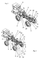
- Fig. 7
- eine Schnittdarstellung des Vorderachsbereichs eines erfindungsgemäßen Fahrgestells im eingefahrenen Zustand mit minimaler Spurweite und
- Fig. 8
- eine Schnittdarstellung des Vorderachsbereichs eines erfindungsgemäßen Fahrgestells im ausgefahrenen Zustand mit maximaler Spurweite.
- Fig. 1
- a schematic representation of a special vehicle on a slope;
- Fig. 2
- a perspective view of a chassis according to the invention in the state with minimum track and ground clearance;
- Fig. 3
- a perspective view of a chassis according to the invention in the state with maximum track and ground clearance;
- Fig. 4
- a partial view of a rear suspension in the retracted state;
- Fig. 5
- a partial view of a rear suspension in the extended state;
- Fig. 6
- a perspective view of the front axle of a chassis according to the invention in the retracted state;
- Fig. 7
- a sectional view of the front axle of a chassis according to the invention in the retracted state with minimum track and
- Fig. 8
- a sectional view of the front axle of a chassis according to the invention in the extended state with maximum track width.
Weiter weist das Spezialfahrzeug 1 Aufbauten 4 auf. Diese Aufbauten 4 sind unter anderem die Motorbaugruppe, das Fahrerhaus und entsprechende fahrzeugspezifische Vorrichtungen, wie Aggregate oder dgl. Weiter weist das Spezialfahrzeug 1 noch Gerätschaften 5 auf. Diese Gerätschaften 5 können beispielsweise wie im dargestellten Ausführungsbeispiel Sprüheinrichtungen großer Arbeitsbreite sein, um beispielsweise Pflanzen zu düngen oder eine Schädlingsbekämpfung an diesen Pflanzen durchzuführen. Zu einer solchen Sprühanordnung gehören insbesondere ein Vorratsbehälter, der auf dem Spezialfahrzeug angeordnet ist und eine Pumpanordnung, sowie ein bedarfsweise ausfahr- oder -klappbares Spritzgestänge mit Spritzdüsen.Next, the special vehicle 1 on 4 structures. These
Das Spezialfahrzeuge 1 fährt in Fahrtrichtung F, also in die Zeichenebene der
Wenn allerdings das Spezialfahrzeug 1 eine Gerätschaft 5 entsprechend einer Spritzanlage, wie hier dargestellt, aufweist, könnte die Spritzanlage nicht effizient und ressourcenschonend arbeiten, da nicht überall ein gleichmäßiger Abstand zu den am Hang befindlichen Pflanzen P vorherrscht. Die Pflanzen P am Hang G würden also mit unterschiedlicher Intensität an Chemikalien, Düngemitteln oder Schädlingsbekämpfungsmitteln bedeckt werden, was zu einer erheblichen negativen Einwirkung auf das Pflanzenwachstum und die Ernte führen würde. Um derartige wirtschaftliche Schädigungen des Bestandes an Pflanzen P zu verhindern wird nunmehr das Spritzgestänge, ebenfalls um einen Winkel α gedreht, so dass das Spritzgestänge und der Hang G Parallel zueinander ausgerichtet sind. Hierdurch wird sichergestellt, dass über den gesamten Wirkbereich der Gerätschaft 5 ein gleichmäßiger Abstand zum Hang G bzw. zu den Pflanzen P besteht.However, if the special vehicle 1 has an
Ein weiterer Vorteil der horizontalen Ausrichtung des Spezialfahrzeuges ist die damit verbundene senkrechte Ausrichtung der Vertikalstellelemente 22 und der Räder 3. Durch diese annähernd senkrechte Ausrichtung der vertikalen Bauteile des Fahrgestells 2 und der Räder 3 wird der Bestand an Pflanzen P geschont. Da die Pflanzen selbst am Hang G senkrecht gen Himmel wachsen, wäre bei Fahrten am Hang G ohne Ausgleich eines Gefälles eine Beschädigung der Pflanzen P wahrscheinlich. Die Räder und auch Teile des Fahrgestells 2 würden Teile der Pflanzen P über- oder umfahren, so dass zumindest in den Reihen rechts R des linken Rades 3 L und rechts R des rechten Rades 3 R die Pflanzen P heruntergedrückt bzw. einfach umgefahren würden. Hierdurch würde ein erheblicher wirtschaftlicher Schaden entstehen, der mit dem erfindungsgemäßen Spezialfahrzeug vermieden werden kann.Another advantage of the horizontal orientation of the special vehicle is the associated vertical alignment of the
In den
Das dargestellte Fahrgestell 2 hat vier Radaufhängungen 21, mit denen sowohl die Höhe des Fahrgestells und damit seine Bodenfreiheit 70 als auch die Spurweite 71 der Räder 3 einstellbar ist. Mit Hilfe der erfindungsgemäßen Ausgestaltung lässt sich die Spurweite 71 zwischen 1,8 m (siehe
Die Anzeige ist in Form eines Computerterminals ausgestaltet, welches darüber hinaus mit einem Bedienschalter zur ferngesteuerten Spurweitenverstellung durch den Fahrer versehen ist. Das Computerterminal ist mit einem Steuergerät verbunden, vorzugsweise einem Computer, über den die elektrohydraulischen Verstelleinheiten steuerbar sind. In dem Computer sind mehrere vorgegebene Werte für Spurweiten abgespeichert, so dass der Fahrer über das Computerterminal lediglich eine passende Spurweite auswählen muss. Darüber hinaus kann der Fahrer auch einen beliebigen Wert für die Spurweite in das Computerterminal eingeben. Selbstverständlich ist die Spurweitenverstellung auch mittels des Bedienschalters direkt vornehmbar, wobei der Fahrer oder eine Hilfsperson die Räder beobachtet, um festzustellen, wann die gewünschte Spurweite 71 erreicht ist.The display is designed in the form of a computer terminal, which is also provided with a control switch for remote control of gauges by the driver. The computer terminal is connected to a control device, preferably a computer, via which the electro-hydraulic adjustment units are controllable. Several predefined values for gauges are stored in the computer so that the driver only has to select a suitable track width via the computer terminal. About that In addition, the driver can also enter any value for the gauge in the computer terminal. Of course, the girth adjustment is also vornehmbar by means of the control switch, the driver or an assistant observing the wheels to determine when the desired
Da die Spurweitenverstellung nur während der Fahrt möglich ist, sorgt eine elektronisch realisierte Sperre in der Steuervorrichtung dafür, dass die Verstellung der Spurweite 71 bei Stillstand der Räder 3 blockiert wird.Since the gage adjustment is possible only while driving, provides an electronically realized lock in the control device that the adjustment of the
Wie man am besten in den
Zur Veränderung der Bodenfreiheit 70 werden die Hydraulikzylinder der Vertikalstelleinheiten 22 an allen vier Radaufhängungen 21 ausgefahren, so dass sich das Fahrgestell 2 insgesamt nach oben bewegt. Dabei steht ein maximaler Verstellweg 20 (siehe
-
Fig. 4 zeigt den Zustand mit vollständig eingefahrenen Vertikalstelleinheiten 22, bei dem eine Bodenfreiheit von 1,15 m erreicht wird. -
Fig. 5 zeigt den Zustand mit vollständig ausgefahrenen Vertikalstelleinheiten 22, bei demeine Bodenfreiheit von 2,0 m erreicht wird.
-
Fig. 4 shows the state with fully retractedvertical adjustment units 22, in which a ground clearance of 1.15 m is achieved. -
Fig. 5 shows the state with fully extendedvertical adjustment units 22, in which a ground clearance of 2.0 m is achieved.
Wie auch bei der Horizontalverstellung ist am Fahrerstand 6 eine Anzeigevorrichtung zur Anzeige der Bodenfreiheit 70 vorgesehen, nämlich in dem oben erwähnten Computerterminal, welches in den Zeichnungen nicht dargestellt ist. Ebenfalls ist an dem Computerterminal ein Bedienschalter zur ferngesteuerten Höhenverstellung durch den Fahrer vom Fahrerstand 6 aus vorgesehen. Dieser kann zwischen vorgegebenen, im Computer gespeicherten Werten für die Bodenfreiheit auswählen, oder einen Wert für die Bodenfreiheit 70 direkt eintippen oder den Bedienschalter solange bedienen, bis die gewünschte Bodenfreiheit 70 erreicht ist.As with the horizontal adjustment of the driver's
Über den Computerterminal können auch Geländeneigungen eingegeben werden, so dass das Spezialfahrzeug mit seinen Vertikalstelleinheiten 22 so angesteuert wird, dass eine gewünschte Orientierung des Fahrzeugs, bevorzugt horizontal, erreicht wird. Dabei kann auch die jeweils momentan gefahrene Fahrtrichtung zum Hang bei der Einstellung der Vertikalstelleinheiten berücksichtigt werden, beispielsweise können bei einer Diagonalfahrt am Hang vier verschiedene Höheneinstellungen eingestellt werden, um das Fahrzeug horizontal auszurichten. Dazu ist es auch möglich, dass am Fahrzeug selbst eine Messeinrichtung für die räumliche Orientierung vorgesehen ist, wobei bei Änderungen in der gemessenen Orientierung sofort eine geeignete Gegensteuerung durch individuelle Veränderung der Höheneinstellung der Vertikalstelleinheiten gegeben ist.On the computer terminal also terrain inclinations can be entered, so that the special vehicle is controlled with its
Des Weiteren ist in dem genannten Bordcomputer eine Antriebssteuervorrichtung realisiert, die einen Geschwindigkeitsbegrenzer aufweist. Im Falle, dass die Bodenfreiheit 70 einen größeren Wert als einen vorgegebenen Grenzwert aufweist, sorgt der Geschwindigkeitsbegrenzer dafür, dass die Fahrgeschwindigkeit des Fahrgestells auf einen ebenfalls vorgegebenen Wert begrenzt wird. Im vorliegenden Fall wird die Fahrgeschwindigkeit elektronisch auf maximal 15 km/h begrenzt, sobald die Bodenfreiheit 70 größer als 1,3 m ist.Furthermore, in the said on-board computer a drive control device is realized, which has a speed limiter. In the event that the
Wie man am besten in den
Wie man am besten in
Für die Horizontalverstellung in Verstellrichtung 72 weist jede Achse zwei Horizontalstelleinheiten 23 auf, die beispielhaft für die Vorderachse 28 in
Eine für die Lenkung der Vorderräder 3 vorgesehene Spurstange 26 ist im Wesentlichen in Form eines weiteren Hydraulikzylinders 27 ausgestaltet, um bei einer Verstellung der Spurweite 71 in Verstellrichtung 72 die Länge der Spurstange 26 an die veränderte Spurweite 71 anzupassen. Die Verstellung der Länge der Spurstange 26 erfolgt synchron zur Verstellung der Spurweite 71 in Verstellrichtung 72.A provided for the steering of the
Die Verstellung der Hinterachse erfolgt ganz analog zur Verstellung der Vorderachse 28, wobei die Horizontalstelleinheit 23 entsprechend ausgebildet sind. Lediglich die Spurstange 26 ist bei der Hinterachse nicht vorgesehen.The adjustment of the rear axle is quite analogous to the adjustment of the
- 11
- Spezialfahrzeugspecial-purpose vehicle
- 22
- Fahrgestellchassis
- 2020
- Verstellweg, vertikalAdjustment, vertical
- 2121
- RadaufhängungArm
- 2222
- VertikalstelleinheitVertical actuator
- 2323
- HorizontalstelleinheitHorizontal adjustment unit
- 2424
- LuftfedereinheitAir suspension unit
- 2525
- Querstabilisatoranti-roll bar
- 2626
- Spurstangetie rod
- 2727
- Hydraulikzylinderhydraulic cylinders
- 2828
- VorderachseFront
- 2929
- GelenklagerSpherical plain bearings
- 33
- Radwheel
- 3131
- Radnabenmotorhub motor
- 44
- Aufbautenconstructions
- 55
- Gerätschaftequipment
- 5151
- WinkelverstellaufnahmeWinkelverstellaufnahme
- 66
- Fahrerstandplatform
- 7070
- Bodenfreiheitground clearance
- 7171
- Spurweitegauge
- 7272
- Verstellrichtungadjustment
- 8181
- äußeres Führungsprofilouter leadership profile
- 8282
- inneres Führungsprofilinner leadership profile
- FF
- Fahrtrichtungdirection of travel
- GG
- Hanghillside
- PP
- Pflanzeplant
- αα
- Anstellwinkel, HanggefälleAngle of attack, slope
- LL
- LinksLeft
- RR
- RechtsRight
Claims (14)
Priority Applications (1)
| Application Number | Priority Date | Filing Date | Title |
|---|---|---|---|
| PL10401066T PL2248690T3 (en) | 2009-05-08 | 2010-05-04 | Frame for special vehicles |
Applications Claiming Priority (1)
| Application Number | Priority Date | Filing Date | Title |
|---|---|---|---|
| DE102009025770A DE102009025770A1 (en) | 2007-11-09 | 2009-05-08 | Chassis for special vehicles according to DE 10 2007 053 906.3 |
Publications (3)
| Publication Number | Publication Date |
|---|---|
| EP2248690A2 true EP2248690A2 (en) | 2010-11-10 |
| EP2248690A3 EP2248690A3 (en) | 2012-05-02 |
| EP2248690B1 EP2248690B1 (en) | 2013-03-27 |
Family
ID=42651407
Family Applications (1)
| Application Number | Title | Priority Date | Filing Date |
|---|---|---|---|
| EP10401066A Active EP2248690B1 (en) | 2009-05-08 | 2010-05-04 | Frame for special vehicles |
Country Status (3)
| Country | Link |
|---|---|
| EP (1) | EP2248690B1 (en) |
| DE (1) | DE102009025770A1 (en) |
| PL (1) | PL2248690T3 (en) |
Cited By (12)
| Publication number | Priority date | Publication date | Assignee | Title |
|---|---|---|---|---|
| WO2012092003A1 (en) * | 2010-12-30 | 2012-07-05 | Agco Corporation | Linkage lift mechanism for off-road vehicle |
| EP2537684A1 (en) * | 2011-06-23 | 2012-12-26 | Haulotte Group | Axle shaft, and vehicle including at least one such axle shaft |
| US9428242B2 (en) | 2014-02-24 | 2016-08-30 | Harley-Davidson Motor Company Group, LLC | Variable ride height systems and methods |
| CN107628144A (en) * | 2017-10-25 | 2018-01-26 | 福建农林大学 | The adjustable probe rod type of driving tread keeps away a fluid pressure underpan and its control method |
| FR3054996A1 (en) * | 2016-08-12 | 2018-02-16 | Artec Pulverisation | AUTOMOTIVE VEHICLE WITH CHASSIS ADJUSTABLE IN HEIGHT |
| CN109278487A (en) * | 2018-11-27 | 2019-01-29 | 辽宁工业大学 | A kind of wheelspan and the adjustable electric automobile chassis system of bodywork height |
| CN109541719A (en) * | 2019-01-18 | 2019-03-29 | 厦门大学嘉庚学院 | Avoidance signal detecting device and its working method |
| CN110502853A (en) * | 2019-08-27 | 2019-11-26 | 北京航天发射技术研究所 | A kind of strength analysis method of the special type vehicle carriage under ground supports |
| EP3303090B1 (en) | 2015-05-25 | 2020-01-08 | Rapid Housing Systems GmbH | Construction set for a modular building with an underriding adjuster |
| CN111038592A (en) * | 2020-01-08 | 2020-04-21 | 吉林工程技术师范学院 | Liftable off-road vehicle frame device |
| US20210155066A1 (en) * | 2018-06-27 | 2021-05-27 | Kubota Corporation | Riding Work Vehicle |
| WO2022043780A1 (en) * | 2020-08-25 | 2022-03-03 | Agco Corporation | System and method for adjusting the chassis height of a machine |
Families Citing this family (2)
| Publication number | Priority date | Publication date | Assignee | Title |
|---|---|---|---|---|
| US9578868B2 (en) | 2013-07-30 | 2017-02-28 | Winfield Solutions, Llc | High clearance adjustable sprayer |
| DK3141114T3 (en) | 2015-09-08 | 2018-12-03 | Herbert Dammann Gmbh | Field Spray and Procedure |
Citations (3)
| Publication number | Priority date | Publication date | Assignee | Title |
|---|---|---|---|---|
| US6311795B1 (en) | 2000-05-02 | 2001-11-06 | Case Corporation | Work vehicle steering and suspension system |
| DE10320291A1 (en) | 2003-05-07 | 2005-01-05 | Wolf-Dieter Wichmann | Hydraulic chassis system for automobile or self-propelled agricultural machine providing matching of ground uneveness, spring suspension with shock absorber function and inclination compensation and stabilization |
| EP1502769A2 (en) | 2003-07-31 | 2005-02-02 | Deere & Company | Agricultural Vehicle |
Family Cites Families (16)
| Publication number | Priority date | Publication date | Assignee | Title |
|---|---|---|---|---|
| GB8407913D0 (en) * | 1984-03-27 | 1984-05-02 | British Res Agricult Eng | Boom assemblies |
| DE3810386A1 (en) * | 1988-03-26 | 1989-10-05 | Daimler Benz Ag | Device for the arbitrary triggering of the raising and lowering of the vehicle body in relation to at least one vehicle axle on a truck with air suspension |
| FR2669804B1 (en) * | 1990-11-29 | 1994-05-20 | Agro Electronique France | AUTOMATIC RETURN DEVICE IN THE REFERENCE POSITION OF A LIQUID OR POWDER DISPENSING RAMP FOR AGRICULTURAL MACHINE OF THE SPRAYER OR FERTILIZER TYPE. |
| FR2734499B1 (en) * | 1995-05-24 | 1997-07-18 | Agrotronix Sa | METHOD OF ADJUSTING THE POSITION OF A SPRAY RAMP |
| US5597172A (en) * | 1995-10-17 | 1997-01-28 | Deere & Company | Sprayer suspension and steering |
| GB9700569D0 (en) * | 1997-01-13 | 1997-03-05 | Knight Brian G | Ground attitude control means |
| US6036206A (en) * | 1997-11-13 | 2000-03-14 | Case Corporation | Traction control and active suspension |
| DE19948407A1 (en) * | 1999-11-04 | 2001-04-12 | Amazonen Werke Dreyer H | Agricultural spreading machine e.g. field sprayer and large area manure spreader and similar with chassis having running wheels also frame on which structural elements |
| FR2809196B1 (en) * | 2000-05-19 | 2004-10-01 | Frema | MOTOR VEHICLE FOR EVOLVING ON A VARIABLE SLOPE SURFACE |
| US20020175467A1 (en) * | 2001-02-28 | 2002-11-28 | Dicus Jack T. | Joystick actuated vehicle suspension control system |
| US7163227B1 (en) * | 2003-12-17 | 2007-01-16 | Burns Kerry C | Multi-position track width sensor for self-propelled agricultural sprayers |
| US7168717B2 (en) * | 2005-01-28 | 2007-01-30 | Deere & Company | High clearance vehicle suspension with twin spindles for transferring steering torque |
| US7611154B2 (en) * | 2006-01-11 | 2009-11-03 | International Truck Intellectual Property Company, Llc | Pneumatic vehicle stabilization system |
| DE102007050252B4 (en) * | 2007-10-20 | 2016-09-15 | Dr. Ing. H.C. F. Porsche Aktiengesellschaft | Level control system of a motor vehicle |
| DE102007053906A1 (en) * | 2007-11-09 | 2009-05-14 | Herbert Dammann Gmbh | Chassis for special vehicles |
| GB0815301D0 (en) * | 2008-08-22 | 2008-09-24 | Chem Europ Bv Ag | Agricultural application machine with single wheel suspension |
-
2009
- 2009-05-08 DE DE102009025770A patent/DE102009025770A1/en not_active Ceased
-
2010
- 2010-05-04 EP EP10401066A patent/EP2248690B1/en active Active
- 2010-05-04 PL PL10401066T patent/PL2248690T3/en unknown
Patent Citations (3)
| Publication number | Priority date | Publication date | Assignee | Title |
|---|---|---|---|---|
| US6311795B1 (en) | 2000-05-02 | 2001-11-06 | Case Corporation | Work vehicle steering and suspension system |
| DE10320291A1 (en) | 2003-05-07 | 2005-01-05 | Wolf-Dieter Wichmann | Hydraulic chassis system for automobile or self-propelled agricultural machine providing matching of ground uneveness, spring suspension with shock absorber function and inclination compensation and stabilization |
| EP1502769A2 (en) | 2003-07-31 | 2005-02-02 | Deere & Company | Agricultural Vehicle |
Cited By (19)
| Publication number | Priority date | Publication date | Assignee | Title |
|---|---|---|---|---|
| US8602137B2 (en) | 2010-12-30 | 2013-12-10 | Agco Corporation | Linkage lift mechanism for off-road vehicle |
| WO2012092003A1 (en) * | 2010-12-30 | 2012-07-05 | Agco Corporation | Linkage lift mechanism for off-road vehicle |
| EP2537684A1 (en) * | 2011-06-23 | 2012-12-26 | Haulotte Group | Axle shaft, and vehicle including at least one such axle shaft |
| FR2976850A1 (en) * | 2011-06-23 | 2012-12-28 | Haulotte Group | HALF AXLE, AND VEHICLE COMPRISING AT LEAST ONE SUCH HALF AXLE |
| US9428242B2 (en) | 2014-02-24 | 2016-08-30 | Harley-Davidson Motor Company Group, LLC | Variable ride height systems and methods |
| US10071785B2 (en) | 2014-02-24 | 2018-09-11 | Harley-Davidson Motor Company Group, LLC | Variable ride height systems and methods |
| EP3303090B1 (en) | 2015-05-25 | 2020-01-08 | Rapid Housing Systems GmbH | Construction set for a modular building with an underriding adjuster |
| FR3054996A1 (en) * | 2016-08-12 | 2018-02-16 | Artec Pulverisation | AUTOMOTIVE VEHICLE WITH CHASSIS ADJUSTABLE IN HEIGHT |
| CN107628144A (en) * | 2017-10-25 | 2018-01-26 | 福建农林大学 | The adjustable probe rod type of driving tread keeps away a fluid pressure underpan and its control method |
| CN107628144B (en) * | 2017-10-25 | 2023-08-18 | 福建农林大学 | Probe type pile avoiding hydraulic chassis with adjustable driving wheel tread and control method thereof |
| US20210155066A1 (en) * | 2018-06-27 | 2021-05-27 | Kubota Corporation | Riding Work Vehicle |
| US11926184B2 (en) * | 2018-06-27 | 2024-03-12 | Kubota Corporation | Riding work vehicle |
| CN109278487A (en) * | 2018-11-27 | 2019-01-29 | 辽宁工业大学 | A kind of wheelspan and the adjustable electric automobile chassis system of bodywork height |
| CN109541719A (en) * | 2019-01-18 | 2019-03-29 | 厦门大学嘉庚学院 | Avoidance signal detecting device and its working method |
| CN110502853B (en) * | 2019-08-27 | 2023-03-17 | 北京航天发射技术研究所 | Method for analyzing strength of special vehicle frame under ground support |
| CN110502853A (en) * | 2019-08-27 | 2019-11-26 | 北京航天发射技术研究所 | A kind of strength analysis method of the special type vehicle carriage under ground supports |
| CN111038592A (en) * | 2020-01-08 | 2020-04-21 | 吉林工程技术师范学院 | Liftable off-road vehicle frame device |
| CN111038592B (en) * | 2020-01-08 | 2021-07-27 | 吉林工程技术师范学院 | Liftable off-road vehicle frame device |
| WO2022043780A1 (en) * | 2020-08-25 | 2022-03-03 | Agco Corporation | System and method for adjusting the chassis height of a machine |
Also Published As
| Publication number | Publication date |
|---|---|
| EP2248690B1 (en) | 2013-03-27 |
| PL2248690T3 (en) | 2013-08-30 |
| EP2248690A3 (en) | 2012-05-02 |
| DE102009025770A1 (en) | 2010-11-11 |
Similar Documents
| Publication | Publication Date | Title |
|---|---|---|
| EP2248690B1 (en) | Frame for special vehicles | |
| EP2058154B1 (en) | Frame for special vehicles | |
| EP1924746B1 (en) | Self-propelled construction machine with lifting columns | |
| EP3357333B1 (en) | Agricultural spreader machine with automatic control of the attenuation of the distributor boom | |
| WO2014121999A1 (en) | Vehicle | |
| WO2015014345A1 (en) | Soil cultivation implement having a device for reconsolidation | |
| DE202011111069U1 (en) | Agricultural vehicle for spraying | |
| DE102014113448A1 (en) | Towing vehicle and hitch for an attachment | |
| DE10120732A1 (en) | Interface between work vehicle and work equipment and control device | |
| DE10346818A1 (en) | Self-propelled mower for green fodder has at least two front mower units, two additional units being mounted on telescopic, swiveling arms on section of vehicle between front and rear axles | |
| EP2839740B1 (en) | Method for motion control, and/or regulation of an agricultural distribution device | |
| EP2559332A1 (en) | Agricultural distributor | |
| DE102005040954A1 (en) | Agricultural tractor ballasting device, has counter balance that is rotatably supported on arm at tractor around horizontal aligned rotational axle, which is aligned parallel to wheel axle of tractor | |
| DE102017214354B3 (en) | Agricultural work vehicle with ground engaging means for transmitting shear forces | |
| EP3912468B1 (en) | Method for motion control, and/or regulation of an agricultural distribution device | |
| WO2017072170A1 (en) | Self-propelled device for working usable spaces | |
| WO2020020885A1 (en) | Self-propelled implement | |
| EP1021943B1 (en) | Agricultural spreader | |
| DE69912671T2 (en) | Device support device especially for agriculture, viticulture and tree nursery | |
| EP4255795A1 (en) | Running gear comprising a crawler drive or wheel drive for vehicles, machines and devices | |
| DE10039600A1 (en) | Plow has shares mounted on consoles each of which can be swivelled by its own hydraulic cylinder, all cylinders being connected in parallel so they can be activated by single control to swivel all shares in same direction simultaneously | |
| EP3081066A1 (en) | Spreading device | |
| DE3630873A1 (en) | EQUIPMENT ATTACHMENT FOR AGRICULTURAL VEHICLES | |
| DE102014220132B4 (en) | Mobile crane and method for supporting such a mobile crane | |
| WO2006040055A1 (en) | Multipurpose vehicle, particularly a harvesting machine or other off-road vehicle |
Legal Events
| Date | Code | Title | Description |
|---|---|---|---|
| PUAI | Public reference made under article 153(3) epc to a published international application that has entered the european phase |
Free format text: ORIGINAL CODE: 0009012 |
|
| AK | Designated contracting states |
Kind code of ref document: A2 Designated state(s): AL AT BE BG CH CY CZ DE DK EE ES FI FR GB GR HR HU IE IS IT LI LT LU LV MC MK MT NL NO PL PT RO SE SI SK SM TR |
|
| AX | Request for extension of the european patent |
Extension state: BA ME RS |
|
| PUAL | Search report despatched |
Free format text: ORIGINAL CODE: 0009013 |
|
| AK | Designated contracting states |
Kind code of ref document: A3 Designated state(s): AL AT BE BG CH CY CZ DE DK EE ES FI FR GB GR HR HU IE IS IT LI LT LU LV MC MK MT NL NO PL PT RO SE SI SK SM TR |
|
| AX | Request for extension of the european patent |
Extension state: BA ME RS |
|
| RIC1 | Information provided on ipc code assigned before grant |
Ipc: A01C 23/00 20060101ALN20120326BHEP Ipc: B60G 9/02 20060101ALN20120326BHEP Ipc: B62D 49/06 20060101ALI20120326BHEP Ipc: B60G 21/10 20060101ALI20120326BHEP Ipc: B62D 63/02 20060101ALN20120326BHEP Ipc: B60B 35/10 20060101ALI20120326BHEP Ipc: B60G 3/01 20060101AFI20120326BHEP Ipc: B60B 23/12 20060101ALN20120326BHEP Ipc: B60G 17/0165 20060101ALI20120326BHEP Ipc: B62D 61/00 20060101ALN20120326BHEP Ipc: A01M 7/00 20060101ALN20120326BHEP |
|
| GRAP | Despatch of communication of intention to grant a patent |
Free format text: ORIGINAL CODE: EPIDOSNIGR1 |
|
| 17P | Request for examination filed |
Effective date: 20121026 |
|
| RIC1 | Information provided on ipc code assigned before grant |
Ipc: B62D 49/06 20060101ALI20121108BHEP Ipc: B60B 23/12 20060101ALN20121108BHEP Ipc: B60G 3/01 20060101AFI20121108BHEP Ipc: B62D 61/00 20060101ALN20121108BHEP Ipc: A01M 7/00 20060101ALN20121108BHEP Ipc: B60G 21/10 20060101ALI20121108BHEP Ipc: B60B 35/10 20060101ALI20121108BHEP Ipc: A01C 23/00 20060101ALN20121108BHEP Ipc: B62D 63/02 20060101ALN20121108BHEP Ipc: B60G 17/0165 20060101ALI20121108BHEP Ipc: B60G 9/02 20060101ALN20121108BHEP |
|
| RIC1 | Information provided on ipc code assigned before grant |
Ipc: B62D 61/00 20060101ALN20121119BHEP Ipc: B60G 17/0165 20060101ALI20121119BHEP Ipc: B60G 21/10 20060101ALI20121119BHEP Ipc: B62D 63/02 20060101ALN20121119BHEP Ipc: A01C 23/00 20060101ALN20121119BHEP Ipc: B60G 9/02 20060101ALN20121119BHEP Ipc: B60B 23/12 20060101ALN20121119BHEP Ipc: B60B 35/10 20060101ALI20121119BHEP Ipc: A01M 7/00 20060101ALN20121119BHEP Ipc: B60G 3/01 20060101AFI20121119BHEP Ipc: B62D 49/06 20060101ALI20121119BHEP |
|
| GRAS | Grant fee paid |
Free format text: ORIGINAL CODE: EPIDOSNIGR3 |
|
| GRAA | (expected) grant |
Free format text: ORIGINAL CODE: 0009210 |
|
| AK | Designated contracting states |
Kind code of ref document: B1 Designated state(s): AL AT BE BG CH CY CZ DE DK EE ES FI FR GB GR HR HU IE IS IT LI LT LU LV MC MK MT NL NO PL PT RO SE SI SK SM TR |
|
| REG | Reference to a national code |
Ref country code: GB Ref legal event code: FG4D Free format text: NOT ENGLISH |
|
| REG | Reference to a national code |
Ref country code: CH Ref legal event code: EP |
|
| REG | Reference to a national code |
Ref country code: AT Ref legal event code: REF Ref document number: 603136 Country of ref document: AT Kind code of ref document: T Effective date: 20130415 |
|
| REG | Reference to a national code |
Ref country code: IE Ref legal event code: FG4D Free format text: LANGUAGE OF EP DOCUMENT: GERMAN |
|
| REG | Reference to a national code |
Ref country code: DE Ref legal event code: R096 Ref document number: 502010002707 Country of ref document: DE Effective date: 20130529 |
|
| PG25 | Lapsed in a contracting state [announced via postgrant information from national office to epo] |
Ref country code: LT Free format text: LAPSE BECAUSE OF FAILURE TO SUBMIT A TRANSLATION OF THE DESCRIPTION OR TO PAY THE FEE WITHIN THE PRESCRIBED TIME-LIMIT Effective date: 20130327 Ref country code: NO Free format text: LAPSE BECAUSE OF FAILURE TO SUBMIT A TRANSLATION OF THE DESCRIPTION OR TO PAY THE FEE WITHIN THE PRESCRIBED TIME-LIMIT Effective date: 20130627 Ref country code: BG Free format text: LAPSE BECAUSE OF FAILURE TO SUBMIT A TRANSLATION OF THE DESCRIPTION OR TO PAY THE FEE WITHIN THE PRESCRIBED TIME-LIMIT Effective date: 20130627 Ref country code: SE Free format text: LAPSE BECAUSE OF FAILURE TO SUBMIT A TRANSLATION OF THE DESCRIPTION OR TO PAY THE FEE WITHIN THE PRESCRIBED TIME-LIMIT Effective date: 20130327 |
|
| REG | Reference to a national code |
Ref country code: LT Ref legal event code: MG4D |
|
| REG | Reference to a national code |
Ref country code: NL Ref legal event code: T3 |
|
| PG25 | Lapsed in a contracting state [announced via postgrant information from national office to epo] |
Ref country code: SI Free format text: LAPSE BECAUSE OF FAILURE TO SUBMIT A TRANSLATION OF THE DESCRIPTION OR TO PAY THE FEE WITHIN THE PRESCRIBED TIME-LIMIT Effective date: 20130327 Ref country code: LV Free format text: LAPSE BECAUSE OF FAILURE TO SUBMIT A TRANSLATION OF THE DESCRIPTION OR TO PAY THE FEE WITHIN THE PRESCRIBED TIME-LIMIT Effective date: 20130327 Ref country code: GR Free format text: LAPSE BECAUSE OF FAILURE TO SUBMIT A TRANSLATION OF THE DESCRIPTION OR TO PAY THE FEE WITHIN THE PRESCRIBED TIME-LIMIT Effective date: 20130628 Ref country code: FI Free format text: LAPSE BECAUSE OF FAILURE TO SUBMIT A TRANSLATION OF THE DESCRIPTION OR TO PAY THE FEE WITHIN THE PRESCRIBED TIME-LIMIT Effective date: 20130327 |
|
| REG | Reference to a national code |
Ref country code: PL Ref legal event code: T3 |
|
| PG25 | Lapsed in a contracting state [announced via postgrant information from national office to epo] |
Ref country code: HR Free format text: LAPSE BECAUSE OF FAILURE TO SUBMIT A TRANSLATION OF THE DESCRIPTION OR TO PAY THE FEE WITHIN THE PRESCRIBED TIME-LIMIT Effective date: 20130327 |
|
| PG25 | Lapsed in a contracting state [announced via postgrant information from national office to epo] |
Ref country code: PT Free format text: LAPSE BECAUSE OF FAILURE TO SUBMIT A TRANSLATION OF THE DESCRIPTION OR TO PAY THE FEE WITHIN THE PRESCRIBED TIME-LIMIT Effective date: 20130729 Ref country code: IS Free format text: LAPSE BECAUSE OF FAILURE TO SUBMIT A TRANSLATION OF THE DESCRIPTION OR TO PAY THE FEE WITHIN THE PRESCRIBED TIME-LIMIT Effective date: 20130727 Ref country code: CZ Free format text: LAPSE BECAUSE OF FAILURE TO SUBMIT A TRANSLATION OF THE DESCRIPTION OR TO PAY THE FEE WITHIN THE PRESCRIBED TIME-LIMIT Effective date: 20130327 Ref country code: RO Free format text: LAPSE BECAUSE OF FAILURE TO SUBMIT A TRANSLATION OF THE DESCRIPTION OR TO PAY THE FEE WITHIN THE PRESCRIBED TIME-LIMIT Effective date: 20130327 Ref country code: ES Free format text: LAPSE BECAUSE OF FAILURE TO SUBMIT A TRANSLATION OF THE DESCRIPTION OR TO PAY THE FEE WITHIN THE PRESCRIBED TIME-LIMIT Effective date: 20130708 Ref country code: EE Free format text: LAPSE BECAUSE OF FAILURE TO SUBMIT A TRANSLATION OF THE DESCRIPTION OR TO PAY THE FEE WITHIN THE PRESCRIBED TIME-LIMIT Effective date: 20130327 Ref country code: SK Free format text: LAPSE BECAUSE OF FAILURE TO SUBMIT A TRANSLATION OF THE DESCRIPTION OR TO PAY THE FEE WITHIN THE PRESCRIBED TIME-LIMIT Effective date: 20130327 |
|
| PG25 | Lapsed in a contracting state [announced via postgrant information from national office to epo] |
Ref country code: CY Free format text: LAPSE BECAUSE OF FAILURE TO SUBMIT A TRANSLATION OF THE DESCRIPTION OR TO PAY THE FEE WITHIN THE PRESCRIBED TIME-LIMIT Effective date: 20130327 |
|
| BERE | Be: lapsed |
Owner name: HERBERT DAMMANN G.M.B.H. Effective date: 20130531 |
|
| PG25 | Lapsed in a contracting state [announced via postgrant information from national office to epo] |
Ref country code: MC Free format text: LAPSE BECAUSE OF FAILURE TO SUBMIT A TRANSLATION OF THE DESCRIPTION OR TO PAY THE FEE WITHIN THE PRESCRIBED TIME-LIMIT Effective date: 20130327 |
|
| PG25 | Lapsed in a contracting state [announced via postgrant information from national office to epo] |
Ref country code: DK Free format text: LAPSE BECAUSE OF FAILURE TO SUBMIT A TRANSLATION OF THE DESCRIPTION OR TO PAY THE FEE WITHIN THE PRESCRIBED TIME-LIMIT Effective date: 20130327 |
|
| PLBE | No opposition filed within time limit |
Free format text: ORIGINAL CODE: 0009261 |
|
| STAA | Information on the status of an ep patent application or granted ep patent |
Free format text: STATUS: NO OPPOSITION FILED WITHIN TIME LIMIT |
|
| REG | Reference to a national code |
Ref country code: IE Ref legal event code: MM4A |
|
| PG25 | Lapsed in a contracting state [announced via postgrant information from national office to epo] |
Ref country code: IT Free format text: LAPSE BECAUSE OF FAILURE TO SUBMIT A TRANSLATION OF THE DESCRIPTION OR TO PAY THE FEE WITHIN THE PRESCRIBED TIME-LIMIT Effective date: 20130327 Ref country code: BE Free format text: LAPSE BECAUSE OF NON-PAYMENT OF DUE FEES Effective date: 20130531 |
|
| 26N | No opposition filed |
Effective date: 20140103 |
|
| REG | Reference to a national code |
Ref country code: HU Ref legal event code: AG4A Ref document number: E018406 Country of ref document: HU |
|
| REG | Reference to a national code |
Ref country code: DE Ref legal event code: R097 Ref document number: 502010002707 Country of ref document: DE Effective date: 20140103 |
|
| PG25 | Lapsed in a contracting state [announced via postgrant information from national office to epo] |
Ref country code: IE Free format text: LAPSE BECAUSE OF NON-PAYMENT OF DUE FEES Effective date: 20130504 |
|
| REG | Reference to a national code |
Ref country code: CH Ref legal event code: PL |
|
| PG25 | Lapsed in a contracting state [announced via postgrant information from national office to epo] |
Ref country code: LI Free format text: LAPSE BECAUSE OF NON-PAYMENT OF DUE FEES Effective date: 20140531 Ref country code: CH Free format text: LAPSE BECAUSE OF NON-PAYMENT OF DUE FEES Effective date: 20140531 |
|
| PG25 | Lapsed in a contracting state [announced via postgrant information from national office to epo] |
Ref country code: MT Free format text: LAPSE BECAUSE OF FAILURE TO SUBMIT A TRANSLATION OF THE DESCRIPTION OR TO PAY THE FEE WITHIN THE PRESCRIBED TIME-LIMIT Effective date: 20130327 |
|
| PG25 | Lapsed in a contracting state [announced via postgrant information from national office to epo] |
Ref country code: SM Free format text: LAPSE BECAUSE OF FAILURE TO SUBMIT A TRANSLATION OF THE DESCRIPTION OR TO PAY THE FEE WITHIN THE PRESCRIBED TIME-LIMIT Effective date: 20130327 |
|
| PG25 | Lapsed in a contracting state [announced via postgrant information from national office to epo] |
Ref country code: TR Free format text: LAPSE BECAUSE OF FAILURE TO SUBMIT A TRANSLATION OF THE DESCRIPTION OR TO PAY THE FEE WITHIN THE PRESCRIBED TIME-LIMIT Effective date: 20130327 |
|
| PG25 | Lapsed in a contracting state [announced via postgrant information from national office to epo] |
Ref country code: MK Free format text: LAPSE BECAUSE OF FAILURE TO SUBMIT A TRANSLATION OF THE DESCRIPTION OR TO PAY THE FEE WITHIN THE PRESCRIBED TIME-LIMIT Effective date: 20130327 Ref country code: LU Free format text: LAPSE BECAUSE OF NON-PAYMENT OF DUE FEES Effective date: 20130504 |
|
| REG | Reference to a national code |
Ref country code: FR Ref legal event code: PLFP Year of fee payment: 7 |
|
| REG | Reference to a national code |
Ref country code: FR Ref legal event code: PLFP Year of fee payment: 8 |
|
| REG | Reference to a national code |
Ref country code: HU Ref legal event code: HC9C |
|
| REG | Reference to a national code |
Ref country code: FR Ref legal event code: PLFP Year of fee payment: 9 |
|
| PG25 | Lapsed in a contracting state [announced via postgrant information from national office to epo] |
Ref country code: AL Free format text: LAPSE BECAUSE OF FAILURE TO SUBMIT A TRANSLATION OF THE DESCRIPTION OR TO PAY THE FEE WITHIN THE PRESCRIBED TIME-LIMIT Effective date: 20130327 |
|
| REG | Reference to a national code |
Ref country code: DE Ref legal event code: R082 Ref document number: 502010002707 Country of ref document: DE Representative=s name: HEESCHEN, SVEN, DIPL.-PHYS., DE |
|
| PGFP | Annual fee paid to national office [announced via postgrant information from national office to epo] |
Ref country code: NL Payment date: 20220518 Year of fee payment: 13 |
|
| PGFP | Annual fee paid to national office [announced via postgrant information from national office to epo] |
Ref country code: HU Payment date: 20220529 Year of fee payment: 13 Ref country code: GB Payment date: 20220523 Year of fee payment: 13 Ref country code: FR Payment date: 20220523 Year of fee payment: 13 Ref country code: DE Payment date: 20220519 Year of fee payment: 13 |
|
| PGFP | Annual fee paid to national office [announced via postgrant information from national office to epo] |
Ref country code: PL Payment date: 20220426 Year of fee payment: 13 Ref country code: AT Payment date: 20220517 Year of fee payment: 13 |
|
| REG | Reference to a national code |
Ref country code: DE Ref legal event code: R119 Ref document number: 502010002707 Country of ref document: DE |
|
| REG | Reference to a national code |
Ref country code: NL Ref legal event code: MM Effective date: 20230601 |
|
| REG | Reference to a national code |
Ref country code: AT Ref legal event code: MM01 Ref document number: 603136 Country of ref document: AT Kind code of ref document: T Effective date: 20230504 |
|
| GBPC | Gb: european patent ceased through non-payment of renewal fee |
Effective date: 20230504 |
|
| PG25 | Lapsed in a contracting state [announced via postgrant information from national office to epo] |
Ref country code: HU Free format text: LAPSE BECAUSE OF NON-PAYMENT OF DUE FEES Effective date: 20230505 Ref country code: AT Free format text: LAPSE BECAUSE OF NON-PAYMENT OF DUE FEES Effective date: 20230504 |
|
| PG25 | Lapsed in a contracting state [announced via postgrant information from national office to epo] |
Ref country code: NL Free format text: LAPSE BECAUSE OF NON-PAYMENT OF DUE FEES Effective date: 20230601 |