EP2034385A2 - Electronic device with circuitry operative to change an orientation of an indicator and method for use therewith - Google Patents
Electronic device with circuitry operative to change an orientation of an indicator and method for use therewith Download PDFInfo
- Publication number
- EP2034385A2 EP2034385A2 EP08252204A EP08252204A EP2034385A2 EP 2034385 A2 EP2034385 A2 EP 2034385A2 EP 08252204 A EP08252204 A EP 08252204A EP 08252204 A EP08252204 A EP 08252204A EP 2034385 A2 EP2034385 A2 EP 2034385A2
- Authority
- EP
- European Patent Office
- Prior art keywords
- electronic device
- mode
- indicator
- orientation
- area
- Prior art date
- Legal status (The legal status is an assumption and is not a legal conclusion. Google has not performed a legal analysis and makes no representation as to the accuracy of the status listed.)
- Withdrawn
Links
Images


Classifications
-
- H—ELECTRICITY
- H01—ELECTRIC ELEMENTS
- H01H—ELECTRIC SWITCHES; RELAYS; SELECTORS; EMERGENCY PROTECTIVE DEVICES
- H01H13/00—Switches having rectilinearly-movable operating part or parts adapted for pushing or pulling in one direction only, e.g. push-button switch
- H01H13/70—Switches having rectilinearly-movable operating part or parts adapted for pushing or pulling in one direction only, e.g. push-button switch having a plurality of operating members associated with different sets of contacts, e.g. keyboard
- H01H13/83—Switches having rectilinearly-movable operating part or parts adapted for pushing or pulling in one direction only, e.g. push-button switch having a plurality of operating members associated with different sets of contacts, e.g. keyboard characterised by legends, e.g. Braille, liquid crystal displays, light emitting or optical elements
-
- G—PHYSICS
- G06—COMPUTING; CALCULATING OR COUNTING
- G06F—ELECTRIC DIGITAL DATA PROCESSING
- G06F1/00—Details not covered by groups G06F3/00 - G06F13/00 and G06F21/00
- G06F1/16—Constructional details or arrangements
- G06F1/1613—Constructional details or arrangements for portable computers
- G06F1/1626—Constructional details or arrangements for portable computers with a single-body enclosure integrating a flat display, e.g. Personal Digital Assistants [PDAs]
-
- G—PHYSICS
- G06—COMPUTING; CALCULATING OR COUNTING
- G06F—ELECTRIC DIGITAL DATA PROCESSING
- G06F1/00—Details not covered by groups G06F3/00 - G06F13/00 and G06F21/00
- G06F1/16—Constructional details or arrangements
- G06F1/1613—Constructional details or arrangements for portable computers
- G06F1/1633—Constructional details or arrangements of portable computers not specific to the type of enclosures covered by groups G06F1/1615 - G06F1/1626
- G06F1/1684—Constructional details or arrangements related to integrated I/O peripherals not covered by groups G06F1/1635 - G06F1/1675
- G06F1/169—Constructional details or arrangements related to integrated I/O peripherals not covered by groups G06F1/1635 - G06F1/1675 the I/O peripheral being an integrated pointing device, e.g. trackball in the palm rest area, mini-joystick integrated between keyboard keys, touch pads or touch stripes
-
- G—PHYSICS
- G06—COMPUTING; CALCULATING OR COUNTING
- G06F—ELECTRIC DIGITAL DATA PROCESSING
- G06F3/00—Input arrangements for transferring data to be processed into a form capable of being handled by the computer; Output arrangements for transferring data from processing unit to output unit, e.g. interface arrangements
- G06F3/01—Input arrangements or combined input and output arrangements for interaction between user and computer
- G06F3/02—Input arrangements using manually operated switches, e.g. using keyboards or dials
- G06F3/023—Arrangements for converting discrete items of information into a coded form, e.g. arrangements for interpreting keyboard generated codes as alphanumeric codes, operand codes or instruction codes
- G06F3/0238—Programmable keyboards
-
- G—PHYSICS
- G06—COMPUTING; CALCULATING OR COUNTING
- G06F—ELECTRIC DIGITAL DATA PROCESSING
- G06F2200/00—Indexing scheme relating to G06F1/04 - G06F1/32
- G06F2200/16—Indexing scheme relating to G06F1/16 - G06F1/18
- G06F2200/161—Indexing scheme relating to constructional details of the monitor
- G06F2200/1614—Image rotation following screen orientation, e.g. switching from landscape to portrait mode
-
- G—PHYSICS
- G06—COMPUTING; CALCULATING OR COUNTING
- G06F—ELECTRIC DIGITAL DATA PROCESSING
- G06F2200/00—Indexing scheme relating to G06F1/04 - G06F1/32
- G06F2200/16—Indexing scheme relating to G06F1/16 - G06F1/18
- G06F2200/163—Indexing scheme relating to constructional details of the computer
- G06F2200/1637—Sensing arrangement for detection of housing movement or orientation, e.g. for controlling scrolling or cursor movement on the display of an handheld computer
-
- H—ELECTRICITY
- H01—ELECTRIC ELEMENTS
- H01H—ELECTRIC SWITCHES; RELAYS; SELECTORS; EMERGENCY PROTECTIVE DEVICES
- H01H2219/00—Legends
- H01H2219/002—Legends replaceable; adaptable
-
- H—ELECTRICITY
- H01—ELECTRIC ELEMENTS
- H01H—ELECTRIC SWITCHES; RELAYS; SELECTORS; EMERGENCY PROTECTIVE DEVICES
- H01H2219/00—Legends
- H01H2219/002—Legends replaceable; adaptable
- H01H2219/014—LED
- H01H2219/016—LED programmable
-
- H—ELECTRICITY
- H01—ELECTRIC ELEMENTS
- H01H—ELECTRIC SWITCHES; RELAYS; SELECTORS; EMERGENCY PROTECTIVE DEVICES
- H01H2219/00—Legends
- H01H2219/054—Optical elements
- H01H2219/062—Light conductor
-
- H—ELECTRICITY
- H04—ELECTRIC COMMUNICATION TECHNIQUE
- H04M—TELEPHONIC COMMUNICATION
- H04M1/00—Substation equipment, e.g. for use by subscribers
- H04M1/02—Constructional features of telephone sets
- H04M1/22—Illumination; Arrangements for improving the visibility of characters on dials
-
- H—ELECTRICITY
- H04—ELECTRIC COMMUNICATION TECHNIQUE
- H04M—TELEPHONIC COMMUNICATION
- H04M1/00—Substation equipment, e.g. for use by subscribers
- H04M1/72—Mobile telephones; Cordless telephones, i.e. devices for establishing wireless links to base stations without route selection
- H04M1/724—User interfaces specially adapted for cordless or mobile telephones
- H04M1/72403—User interfaces specially adapted for cordless or mobile telephones with means for local support of applications that increase the functionality
- H04M1/72442—User interfaces specially adapted for cordless or mobile telephones with means for local support of applications that increase the functionality for playing music files
-
- H—ELECTRICITY
- H04—ELECTRIC COMMUNICATION TECHNIQUE
- H04M—TELEPHONIC COMMUNICATION
- H04M2250/00—Details of telephonic subscriber devices
- H04M2250/12—Details of telephonic subscriber devices including a sensor for measuring a physical value, e.g. temperature or motion
-
- H—ELECTRICITY
- H04—ELECTRIC COMMUNICATION TECHNIQUE
- H04M—TELEPHONIC COMMUNICATION
- H04M2250/00—Details of telephonic subscriber devices
- H04M2250/22—Details of telephonic subscriber devices including a touch pad, a touch sensor or a touch detector
Landscapes
- Engineering & Computer Science (AREA)
- Theoretical Computer Science (AREA)
- General Engineering & Computer Science (AREA)
- Computer Hardware Design (AREA)
- Human Computer Interaction (AREA)
- Physics & Mathematics (AREA)
- General Physics & Mathematics (AREA)
- Position Input By Displaying (AREA)
- Control Of Indicators Other Than Cathode Ray Tubes (AREA)
Abstract

Description
- Electronic devices, such as digital media players, have several user interface elements, whose function can be indicated by indicators printed on or near the user interface elements. Consider, for example, an MP3 player having four buttons (play/pause, forward, menu/option, and reverse) positioned at twelve o'clock, three o'clock, six o'clock, and nine o'clock positions (as seen from a user viewing the buttons when the MP3 player is viewed in its intended orientation). To indicate the function of each button, an indicator (e.g., an icon or word/phrase) can be printed on or near each button. In this way, a user will readily know which button to push for a desired function.
- Some electronic devices with a display device have the capability of displaying images in either landscape or portrait mode. When images are displayed in landscape mode, the user typically rotates the
electronic device 90 degrees. It may be desired to keep the same functional configuration of buttons irrespective of the position of the electronic device (e.g., the button at the twelve o'clock position is play/pause in both the landscape and portrait modes). If the indicators on or near the buttons are printed or are otherwise in a fixed orientation, when a user rotates theelectronic device 90 degrees counter-clockwise to view the display in landscape mode, the play/pause indicator will now be at the nine o'clock position even though the button at the twelve o'clock position performs the play/pause functionality. Additionally, the forward and reverse indicators, which were on or near the "left" and "right" buttons in the portrait orientation would be on or near the "up" and "down" buttons in the landscape orientation. Accordingly, the indicators are now mis-descriptive of the functions of the buttons. Additionally, the indicator itself would be oriented 90 degrees counter-clockwise (e.g., a play arrow pointing to the right when at the twelve o'clock position would be pointing "up" at the nine o'clock position). By not being in the correct orientation, such indicators can compromise the user experience. - The present invention is defined by the claims, and nothing in this section should be taken as a limitation on those claims.
- By way of introduction, the embodiments described below provide an electronic device with circuitry operative to change an orientation of an indicator and method for use therewith. In one embodiment, an electronic device is provided comprising a display device, a user interface element, an indicator displayed outside of the display device, and circuitry operative to change an orientation of the indicator when the electronic device changes between a first mode of operation and a second mode of operation.
- In another embodiment, an electronic device is provided comprising a display device, a user interface element, a first area outside of the display device, a first light source positioned under the first area, wherein, when illuminated, the first light source causes the first area to display an indicator in a first orientation, a second area outside of the display device, a second light source positioned under the second area, wherein, when illuminated, the second light source causes the second area to display the indicator in a second orientation, and circuitry operative to illuminate the first light source when the electronic device is in a first mode of operation and illuminate the second light source when the electronic device is in a second mode of operation.
- In yet another embodiment, a portable digital media player is provided comprising a display device, a memory, a user interface element, a first area outside of the display device, a first light source positioned under the first area, a first semi-transparent area disposed over the first light source, wherein the first semi-transparent area comprises an image of an indicator in a first orientation, a second area outside of the display device, a second light source positioned under the second area, a second semi-transparent area disposed over the second light source, wherein the second semi-transparent area comprises an image of the indicator in a second orientation, and circuitry operative to illuminate the first light source when the electronic device is in a first mode of operation and illuminate the second light source when the electronic device is in a second mode of operation, wherein the circuitry is further operative to play digital media content stored in the memory. Methods for use with such electronic devices are also provided. Other embodiments are disclosed, and each of the embodiments can be used alone or together in combination.
- The embodiments will now be described with reference to the attached drawings.
-
Figure 1A is an illustration of an electronic device of an embodiment in which indicators are displayed in a first orientation. -
Figure 1B is an illustration of an electronic device of an embodiment in which indicators are displayed in a second orientation. -
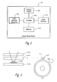
Figure 2 is a block diagram of an electronic device of an embodiment. -
Figure 3 is an illustration of components of an electronic device of an embodiment. -
Figure 4 is an illustration of a semi-transparent layer of an embodiment. -
Figure 5 is a flowchart illustrating an operation of a digital media player of an embodiment. -
Figure 6 is an illustration of a light pipe of an embodiment. - By way of introduction, the embodiments described below generally relate to electronic devices. An electronic device refers to a device that uses electricity for some or all of its functionality. Examples of electronic devices include, but are not limited to, a digital media player (e.g., an MP3 (or other music format) player, a video player, etc.), a game device, a digital camera, a mobile phone, a computer, a text messaging device, a personal digital assistant (PDA), and a remote control. An electronic device can be a wired or wireless device. An electronic device can be portable (e.g., very easy for a user to carry from one location to another) and handheld (e.g., the device can be operated without a desktop or other surface), such as when the electronic device takes the form of a digital media player or mobile phone. However, an electronic device can take a more stationary form, such as a relatively large device intended to be used on a desktop or other surface (e.g., a controller for a large number of separate devices). Although any type of electronic device can be used with these embodiments, the following description and drawings will be presented in terms of a portable digital media player. As used herein, the term "media" generally refers to audio and/or (still or moving) video (with or without audio), and the "player" can refer to a device that plays but does not record or a device that both plays and records digital content (from an internal or external source).
- Turning now to the drawings,
Figure 1A is an illustration of aportable media player 10 of an embodiment. As shown inFigure 1 , theplayer 10 in this embodiment comprises ahousing 20 and adisplay device 30 visible through a portion of thehousing 20. Thedisplay device 30 can take any suitable form and, in one embodiment, is a liquid crystal display (LCD). Thedisplay device 30 is used in this embodiment to display a graphical user interface ("GUI") to facilitate user interaction with theplayer 10. Theportable media player 10 also comprises a plurality ofuser interface elements indicators display device 30 but near some of theuser interface elements digital media player 10 can comprise additional components that are not shown inFigure 1 to simplify the drawing. These components can include, but are not limited to, a power input port, a power switch, an audio output port (e.g., a headphone jack), a video output port, a data port (e.g., a USB jack), a memory card slot, and a wireless (e.g., RF or IR) transmitter and/or receiver. - As used herein, a user interface element (or "user input element") refers to any type of component that facilitates user interaction with the electronic device (in this embodiment, with the player 10). A user input element can take any form including, but not limited to, a tactile element (such as a movable button, wheel, lever, switch, knob, etc.) or a touch-sensitive element (such as a capacitive or other type of touch pad that can sense contact (e.g., single contact or multiple contact (i.e., "tapping") and/or movement (e.g., linear, rotationally, etc.) of an object, such as a finger or stylus). One or more of the user interface elements can be used to allow a user to interact with a graphical user interface displayed on the display device 30 (e.g., by scrolling through multiple items, such as a list of songs or options, displayed on the graphical user interface). One or more of the user interface elements can instead be used to directly issue a command (i.e., without going through the graphical user interface) to the perform a function of the media player 10 (e.g., changing the volume, scrolling through pictures or frames in a moving video, performing a function in a game, etc.). As also used herein, an "indicator" refers to any indicia that can indicate a function of a user interface element. An indicator can take any suitable form, such as, but not limited to, an icon, one or more alpha-numeric characters, a symbol, a color, etc.
- In
Figure 1 , the user interface elements comprise abutton 42, a circular, touch-sensitive pad 50, andfours buttons sensitive pad 50. (In other embodiments, instead of a touch-sensitive scroll wheel, a scroll wheel that physically turns can be used (e.g., a mechanical encoder that turns in a circular motion). Also, instead of a physical button, a touch-sensitive button can be used.) Thefours buttons sensitive pad 50 that overlies the button. In this embodiment, there are three displayed indicators: ahome icon 60, a play/pause icon 62 (at the twelve o'clock position around the circular, touch-sensitive pad 50), and an options icon 64 (at the six o'clock position around the circular, touch-sensitive pad 50). (More or fewer indicators can be used in other embodiments.) Pressing thebutton 42 near thehome icon 60 causes themedia player 10 to display a "home" menu on thedisplay device 30, pressing thebutton 52 under the touch-sensitive pad 50 near the play/pause icon 62 causes themedia player 10 to play/pause a song, movie, or other media content, and pressing thebutton 56 under the touch-sensitive pad 50 near theoption icon 64 causes themedia player 10 to display one or more options on thedisplay device 30. - Although the
indicators Figure 1 as being displayed adjacent to their respectiveuser interface elements home icon 60 is displayed onbutton 42 or when the play/pause icon is displayed on the area of the circular, touch-sensitive pad 50 that overliesbutton 52. Also, it should be noted that players or other electronic devices in other embodiments can have more or fewer user interface elements and indicators (even just one user interface element and/or indicator) than theplayer 10 shown inFigure 1 . Also, as shown inFigure 1 , there is not necessarily a one-to-one correspondence between the user interface elements and indicators (e.g., theplayer 10 inFigure 1 does not contain a displayed indicator indicating the function of the touch-sensitive pad 50). Further, while theindicators housing 20, some or all of theindicators -
Figure 2 is a block diagram of the internal components of theplayer 10 that are housed by thehousing 20. As shown inFigure 2 , theplayer 10 comprises thedisplay device 30, user interface elements (generally indicated here as 90),circuitry 100 operative to change an orientation of the indicator when theplayer 10 changes between a first mode of operation and a second mode of operation, memory devices (generally indicated here as memory 110), andlight sources 120. (Although theuser interface elements 90 are shown separately from thedisplay device 30, these two components can be combined, such as when thedisplay device 30 takes the form of a touch screen.) Thememory 110 in theplayer 10 can take any suitable form (preferably solid state memory, but magnetic, optical, or other types of memory can be used) and can be used to store digital media for playback on theplayer 10 and software/firmware used for the operation of theplayer 10. Other components of theplayer 10 are not shown inFigure 2 to simply the drawing. These other components can include, but are not limited to, an amplifier, digital-to-analog converters, etc. - As mentioned above, the
player 10 comprisescircuitry 100 operative to change an orientation of the indicator when theplayer 10 changes between first and second modes of operation. "Circuitry" can include one or more components and be a pure hardware implementation and/or a combined hardware/software (or firmware) implementation. Accordingly, "circuitry" can take the form of one or more of a microprocessor or processor and a computer-readable medium that stores computer-readable program code (e.g., software or firmware) executable by the (micro)processor, logic gates, switches, an application specific integrated circuit (ASIC), a programmable logic controller, and an embedded microcontroller, for example. As mentioned above, thecircuitry 100 in this embodiment is operative to change an orientation of the indicator when theplayer 10 changes between a first mode of operation and a second mode of operation (as explained below, this can take the form of selectively illuminating various ones of thelight sources 120 in the first and second modes of operation). Thecircuitry 100 can be operative to perform other functions as well, such as playing digital media content stored in thememory 110 or other operations of theplayer 10. - A "mode of operation" can take any suitable form. In one embodiment, the
player 10 is in one mode of operation when theplayer 10 displays images (still or moving video) on thedisplay device 30 in portrait mode and in another mode of operation when theplayer 10 displays images on thedisplay device 30 in landscape mode. Theplayer 10 can change modes of operation manually or automatically. In one embodiment, theplayer 10 changes between the first and second modes of operation in response to user selection via auser interface element 10. For example, the user can change the player's mode of operation by pressing a dedicated button or by using one or more user interface elements to select an option displayed on thedisplay device 30. The displayed option can explicitly describe the mode change (e.g., "portrait mode" and "landscape mode") or can implicitly describe the change (e.g., choosing "video" or "pictures" from a menu will cause theplayer 10 to change to a landscape mode). In another embodiment, theplayer 10 can contain position sensors that detect when a user rotates theplayer 10 to a sideways or landscape orientation and automatically change the operation of theplayer 10 to landscape operation. While landscape and portrait modes were used in these examples, it should be understood that "mode of operation" can include other types of modes. - As discussed in the background section above, if the indicators on or near user interface elements of the player are printed or are otherwise in a fixed orientation, when a user rotates the
player 90 degrees counter-clockwise to view the display device in landscape mode, the indicators can be confusing or even mis-descriptive. To allow a user experience to be equally intuitive in both portrait and landscape modes, thecircuitry 100 in this embodiment is operative to change an orientation of an indicator when theplayer 10 changes between first and second modes of operation (e.g., between portrait and landscape modes). The following paragraphs provide examples of some of the many mechanisms that can be used to provide this functionality. It should be understood that these are merely examples and that features from these examples should not be read into the claims unless explicitly recited therein. - In this particular embodiment, there are
various areas display device 30. Under each of theareas circuitry 100 is operative to change an orientation of an indicator by selectively illuminating one or more of the light sources. This will be illustrated in more detail with respect toFigures 3 and4 . -
Figure 3 showsarea 71 on theplayer 10 and components in thehousing 20 of the player. Specifically, underarea 71 is alight source 200 that is located on acircuit board 210. Thelight source 200 is preferably a light-emitting diode ("LED"), although any type oflight source 200 can be used. Over thelight source 200 is asemi-transparent layer 220 that comprises an image ofindicator 62. Thesemi-transparent layer 220 is preferably a foil layer made of an in-mold decoration ("IDM").Indicator 62 is preferably printed in a 30% transparency, so when thelight source 200 is not illuminated,indicator 62 is not visible. When thelight source 200 is illuminated, thelight source 200 causesindicator 62 to be visible inarea 71 on theplayer 10. In this embodiment, aclear plastic layer 230 is disposed under thesemi-transparent layer 220 to support thesemi-transparent layer 220 and assist in the display of theindicator 62. - As shown in
Figure 4 , in addition toindicator 62, thesemi-transparent layer 220 also comprises images of the other indicators shown inFigure 1A : thehome icon 60 and theoptions icon 64. In addition, thesemi-transparent layer 220 comprises images of these indicators in different positions and orientation. Specifically, thesemi-transparent layer 220 comprise an image of another play/pause icon 62' oriented 90 degrees clockwise from play/pause icon 62 and located at the three o'clock position, another options icon 64' oriented 90 degrees clockwise fromoptions icon 64 and located at the nine o'clock position, and another home icon 60' oriented 90 degrees clockwise fromhome icon 60 and located at the opposite corner near the cut-out forbutton 42. When theplayer 10 is in the first mode of operation (as shown inFigure 1A ), thecircuitry 100 illuminates the light sources underareas areas indicators player 10 is in the second mode of operation (as shown inFigure 1B ), thecircuitry 100 illuminates the light sources underareas areas indicators player 10 is rotated 90 degrees counter-clockwise, the indicators 62', 64', 60' will be in the correct orientation and position, thereby enhancing the user experience. -
Figure 5 is aflow chart 300 illustrating the operation of theplayer 10 in this particular embodiment. It should again be noted that this is merely an example, and details of this example should not be read into the claims. When theplayer 10 is powered on (act 310), the icons default to the portrait mode (i.e., the first mode of operation) (act 320). That is, the light sources underareas icons display device 30 and presses select (the button in the center of the circular, touch-sensitive pad 50) (act 330). Pressing the select button allows the circuitry 100 (here, a processor executing firmware) to turn off/on the appropriate LEDs (act 340). Specifically, when theplayer 10 goes into the second mode of operation, the image in the GUI displayed in thedisplay device 30 switches from portrait to landscape, and thecircuitry 100 turns off the "portrait" LEDs and turns on the "landscape" LEDs (act 350). The icons would then be oriented in a landscape orientation (act 360). - There are many alternatives that can be used with these embodiments. For example, in the above example, there was one only indicator that could be displayed at a given position, and that indicator was either illuminated or not illuminated depending on the mode of operation of the
player 10. For example,area 71 of theplayer 10 only contained a single indicator (play/pause icon 62), which was illuminated in the first mode of operation but not in the second mode of operation. Because of this, although there are fourbuttons sensitive pad 50, with the structure described above, only two of the buttons have displayed indicators near them at any one time. Accordingly, even thoughbuttons areas un-displayed indicators 62' and 64.' - In alternate embodiments, different type of structures can be used so that more than one indicator can be associated with a given area. For example, as shown in
Figure 6 , alight pipe 400 can be used below a given area. Thelight pipe 400 is designed so there are images of two or more indicators within thelight pipe 400. In the example shown inFigure 6 , there are images of two indicators: play/pause and home. There are two light sources positioned adjacent the light pipe 400:green LEDs 410 andred LEDs 420. Each color LED reflects light at different angles. Because the images of the two indicators are positioned in thelight pipe 400 at those different angles, illuminating one of theLEDs LEDs player 10, eacharea buttons areas - Other alternatives can be used. For example, in the above embodiments, an indicator was displayed adjacent to its associated user interface element. In an alternate embodiment, one or more of the indicators can be displayed on the user interface element. (If a movable disc is used instead of a touch-
sensitive pad 50, the disc could contain a transparent ring, be made of a transparent/translucent materials, etc. to allow the indicator to be viewable even when the disc moves.) In another alternative, by "blinking" the light sources on and off, thecircuitry 100 can create an animated effect. In addition to drawing attention to the change of modes, the blinking lights can be used to indicate to the user which way to turn a user interface element, such as a wheel/disc, or indicate that the wheel/disc is being turned. As the wheel/disc is being rotated, a plurality of light sources arranged on, under, or near the wheel/disc can be sequentially illuminated to provide the appearance of movement of the lights. In another alternate embodiment, indicators may be displayed using different colors. For example, when theplayer 10 is in the first mode of operation, all indicators can be shown in one color to indicate portrait mode, and, when theplayer 10 is in the second mode of operation, all indicators can be shown in another color to indicate the landscape mode. - It should be noted that the orientation of the indicator can be changed with or without changing the position of the indicator. For example, in the embodiments shown in
Figures 1A and 1B , the position of the indicator along with the orientation of the indicator changes. However in embodiments where more than one indicator can be associated with an area (e.g., by using a light pipe or a second display device, the orientation of the indicator can change without changing the position of the indicator. Accordingly, an indicator can change orientation with our without changing position, and changing position should not be read into the claims unless explicitly recited therein. - Some of the following claims may state that a component is operative to perform a certain function or configured for a certain task. It should be noted that these are not restrictive limitations. It should also be noted that the acts recited in the claims can be performed in any order - not necessarily in the order in which they are recited.
- It is intended that the foregoing detailed description be understood as an illustration of selected forms that the invention can take and not as a definition of the invention. It is only the following claims, including all equivalents, that are intended to define the scope of this invention. Finally, it should be noted that any aspect of any of the preferred embodiments described herein can be used alone or in combination with one another.
Claims (10)
- A method for changing an orientation of an indicator, the method comprising:(a) displaying an indicator outside of a display device of an electronic device;(b) determining that a mode of the electronic device is being changed from a first mode of operation to a second mode of operation; and(c) changing an orientation of the indicator in response to the mode of the electronic device being changed to the second mode of operation.
- The method of Claim 1, wherein the indicator is displayed in a first orientation in a first area on the electronic device when the electronic device is in the first mode of operation, and wherein the indicator is displayed in a second orientation in a second area on the electronic device when the electronic device is in the second mode of operation.
- The method of Claim 2, wherein the orientation of the indicator is changed by illuminating a first light source positioned under a first area of the electronic device when the electronic device is in the first mode of operation and illuminating a second light source positioned under a second area of the electronic device when the electronic device is in the second mode of operation.
- The method of Claim 1, wherein the electronic device changes between the first mode of operation and the second mode of operation in response to user selection via a user interface element of the electronic device.
- The method of Claim 1, wherein the electronic device changes between the first mode of operation and the second mode of operation in response to a position of the electronic device.
- The method of Claim 1, wherein the electronic device comprises a portable digital media player.
- The method of Claim 1, wherein the display device displays images in a portrait style when the electronic device is in one of the first and second modes of operation, and wherein the display device displays images in a landscape style when the electronic device is in the other of the first and second modes of operation.
- An electronic device comprising:a display device;a user interface element;a first area outside of the display device;a first light source positioned under the first area, wherein, when illuminated, the first light source causes the first area to display an indicator in a first orientation;a second area outside of the display device;a second light source positioned under the second area, wherein, when illuminated, the second light source causes the second area to display the indicator in a second orientation; andcircuitry operative to illuminate the first light source when the electronic device is in a first mode of operation and illuminate the second light source when the electronic device is in a second mode of operation.
- The electronic device of Claim 8 further comprising:a first semi-transparent area disposed over the first light source, wherein the first semi-transparent area comprises an image of the indicator in the first orientation; anda second semi-transparent area disposed over the second light source, wherein the second semi-transparent area comprises an image of the indicator in a second orientation.
- The electronic device of Claim 8, wherein the display device displays images in a portrait style when the electronic device is in one of the first and second modes of operation, and wherein the display device displays images in a landscape style when the electronic device is in the other of the first and second modes of operation.
Applications Claiming Priority (1)
| Application Number | Priority Date | Filing Date | Title |
|---|---|---|---|
| US11/899,984 US20090066506A1 (en) | 2007-09-07 | 2007-09-07 | Electronic device with circuitry operative to change an orientation of an indicator and method for use therewith |
Publications (2)
| Publication Number | Publication Date |
|---|---|
| EP2034385A2 true EP2034385A2 (en) | 2009-03-11 |
| EP2034385A3 EP2034385A3 (en) | 2010-06-02 |
Family
ID=39730596
Family Applications (1)
| Application Number | Title | Priority Date | Filing Date |
|---|---|---|---|
| EP08252204A Withdrawn EP2034385A3 (en) | 2007-09-07 | 2008-06-27 | Electronic device with circuitry operative to change an orientation of an indicator and method for use therewith |
Country Status (3)
| Country | Link |
|---|---|
| US (1) | US20090066506A1 (en) |
| EP (1) | EP2034385A3 (en) |
| CN (1) | CN101382864A (en) |
Cited By (1)
| Publication number | Priority date | Publication date | Assignee | Title |
|---|---|---|---|---|
| EP2428873A1 (en) * | 2010-09-10 | 2012-03-14 | HTC Corporation | Portable electronic device and switching method of icons |
Families Citing this family (6)
| Publication number | Priority date | Publication date | Assignee | Title |
|---|---|---|---|---|
| US20090088876A1 (en) * | 2007-09-28 | 2009-04-02 | Conley Kevin M | Portable, digital media player and associated methods |
| WO2009072240A1 (en) * | 2007-12-07 | 2009-06-11 | Panasonic Corporation | Electronic device |
| US20120206488A1 (en) * | 2011-02-16 | 2012-08-16 | Glenn Wong | Electronic device with a graphic feature |
| CN102760129A (en) * | 2011-04-27 | 2012-10-31 | 腾讯科技(深圳)有限公司 | Network map comment information displaying method and device, and information processing system |
| DE102013224590B4 (en) * | 2012-12-03 | 2019-07-18 | Canon Kabushiki Kaisha | DISPLAY DEVICE AND ITS CONTROL METHOD |
| EP3926414A1 (en) * | 2020-06-17 | 2021-12-22 | ETA SA Manufacture Horlogère Suisse | Display device and related method |
Citations (6)
| Publication number | Priority date | Publication date | Assignee | Title |
|---|---|---|---|---|
| EP1263193A2 (en) * | 2001-05-31 | 2002-12-04 | Nokia Corporation | Mobile station including a display element |
| US6538636B1 (en) * | 1999-07-06 | 2003-03-25 | Intel Corporation | Apparatus and method for configuring a hand-held interactive device |
| US20040201595A1 (en) * | 2003-04-11 | 2004-10-14 | Microsoft Corporation | Self-orienting display |
| US20070004451A1 (en) * | 2005-06-30 | 2007-01-04 | C Anderson Eric | Controlling functions of a handheld multifunction device |
| EP1758140A1 (en) * | 2005-07-26 | 2007-02-28 | Sony Ericsson Mobile Communications AB | Arrangement for generating dual images |
| EP1850218A2 (en) * | 2006-04-28 | 2007-10-31 | Samsung Electronics Co., Ltd. | Method and apparatus to control screen orientation of user interface of portable device |
Family Cites Families (41)
| Publication number | Priority date | Publication date | Assignee | Title |
|---|---|---|---|---|
| GB1521871A (en) * | 1976-01-13 | 1978-08-16 | Random Electronics Int Pty Ltd | Graphic display systems |
| US4828153A (en) * | 1983-12-07 | 1989-05-09 | Motorola, Inc. | Detachable belt clip assembly |
| US5379490A (en) * | 1993-01-04 | 1995-01-10 | Motorola | Belt clip assembly |
| US6122526A (en) * | 1997-04-24 | 2000-09-19 | Eastman Kodak Company | Cellular telephone and electronic camera system with programmable transmission capability |
| US5664292A (en) * | 1996-08-22 | 1997-09-09 | E Lead Electronic Co., Ltd. | Separable clip assembly |
| US6743104B1 (en) * | 1999-11-18 | 2004-06-01 | Nintendo Co., Ltd. | Portable game machine |
| US6125513A (en) * | 1999-11-29 | 2000-10-03 | Motorola | Multifunctional belt clip for a portable device |
| US6443340B1 (en) * | 2000-06-21 | 2002-09-03 | Motorola, Inc. | Spring system for cellular telephone holster |
| US6593914B1 (en) * | 2000-10-31 | 2003-07-15 | Nokia Mobile Phones Ltd. | Keypads for electrical devices |
| US7046230B2 (en) * | 2001-10-22 | 2006-05-16 | Apple Computer, Inc. | Touch pad handheld device |
| USD469109S1 (en) * | 2001-10-22 | 2003-01-21 | Apple Computer, Inc. | Media player |
| US6742685B2 (en) * | 2002-01-04 | 2004-06-01 | Thomas Williams | Clip and holder for portable devices |
| USD489052S1 (en) * | 2002-03-01 | 2004-04-27 | Kabushiki Kaisha Toshiba | Digital audio player |
| US6591085B1 (en) * | 2002-07-17 | 2003-07-08 | Netalog, Inc. | FM transmitter and power supply/charging assembly for MP3 player |
| US6977675B2 (en) * | 2002-12-30 | 2005-12-20 | Motorola, Inc. | Method and apparatus for virtually expanding a display |
| USD486813S1 (en) * | 2003-01-21 | 2004-02-17 | Bluetek Co., Ltd. | MP3 player |
| USD497618S1 (en) * | 2003-04-25 | 2004-10-26 | Apple Computer, Inc. | Media device |
| US7281214B2 (en) * | 2003-06-02 | 2007-10-09 | Apple Inc. | Automatically updating user programmable input sensors to perform user specified functions |
| US7280346B2 (en) * | 2003-09-29 | 2007-10-09 | Danger, Inc. | Adjustable display for a data processing apparatus |
| CA106580S (en) * | 2004-01-05 | 2005-10-31 | Apple Computer | Media device |
| USD516576S1 (en) * | 2004-06-24 | 2006-03-07 | Apple Computer, Inc. | Media device |
| JP2006053629A (en) * | 2004-08-10 | 2006-02-23 | Toshiba Corp | Electronic equipment, control method and control program |
| USD513512S1 (en) * | 2004-09-14 | 2006-01-10 | Tatung Co., Ltd. | Personal portable multimedia player |
| USD511347S1 (en) * | 2004-09-21 | 2005-11-08 | Kabushiki Kaisha Toshiba | Digital audio player |
| USD529044S1 (en) * | 2004-12-23 | 2006-09-26 | Apple Computer, Inc. | Media device |
| USD553640S1 (en) * | 2004-12-28 | 2007-10-23 | Victor Company Of Japan Limited | MP3 player |
| USD521023S1 (en) * | 2005-06-02 | 2006-05-16 | Samsung Electronics Co., Ltd. | MP3 player |
| USD533566S1 (en) * | 2005-07-13 | 2006-12-12 | Coby Electronics Corporation | Digital audio player |
| USD548747S1 (en) * | 2005-08-24 | 2007-08-14 | Apple Inc. | Media device |
| USD541299S1 (en) * | 2005-08-24 | 2007-04-24 | Apple Computer, Inc. | Media device |
| USD538820S1 (en) * | 2005-08-24 | 2007-03-20 | Apple Computer, Inc. | Media device |
| USD541298S1 (en) * | 2005-08-24 | 2007-04-24 | Apple Computer, Inc. | Media device |
| USD541297S1 (en) * | 2005-08-24 | 2007-04-24 | Apple Computer, Inc. | Media device |
| USD549237S1 (en) * | 2005-08-24 | 2007-08-21 | Apple Inc. | Media device |
| USD536691S1 (en) * | 2005-09-14 | 2007-02-13 | Lg Electronics Inc. | Cellular phone |
| USD532425S1 (en) * | 2005-10-11 | 2006-11-21 | Samsung Electronics Co., Ltd. | MP3 player |
| USD537810S1 (en) * | 2005-11-23 | 2007-03-06 | Cowon Systems, Inc. | Digital audio player |
| USD538779S1 (en) * | 2006-03-28 | 2007-03-20 | Olympus Corporation | Digital voice recorder |
| USD543554S1 (en) * | 2006-04-14 | 2007-05-29 | Zewu Dai | MP3 player |
| USD559266S1 (en) * | 2006-06-19 | 2008-01-08 | Jwin Electronics Corp. | Portable MP3 player with FM transmitter with built in car adapter |
| USD558793S1 (en) * | 2006-12-27 | 2008-01-01 | Kabushiki Kaisha Toshiba | Digital audio player |
-
2007
- 2007-09-07 US US11/899,984 patent/US20090066506A1/en not_active Abandoned
-
2008
- 2008-06-27 EP EP08252204A patent/EP2034385A3/en not_active Withdrawn
- 2008-08-15 CN CNA2008101351993A patent/CN101382864A/en active Pending
Patent Citations (6)
| Publication number | Priority date | Publication date | Assignee | Title |
|---|---|---|---|---|
| US6538636B1 (en) * | 1999-07-06 | 2003-03-25 | Intel Corporation | Apparatus and method for configuring a hand-held interactive device |
| EP1263193A2 (en) * | 2001-05-31 | 2002-12-04 | Nokia Corporation | Mobile station including a display element |
| US20040201595A1 (en) * | 2003-04-11 | 2004-10-14 | Microsoft Corporation | Self-orienting display |
| US20070004451A1 (en) * | 2005-06-30 | 2007-01-04 | C Anderson Eric | Controlling functions of a handheld multifunction device |
| EP1758140A1 (en) * | 2005-07-26 | 2007-02-28 | Sony Ericsson Mobile Communications AB | Arrangement for generating dual images |
| EP1850218A2 (en) * | 2006-04-28 | 2007-10-31 | Samsung Electronics Co., Ltd. | Method and apparatus to control screen orientation of user interface of portable device |
Cited By (2)
| Publication number | Priority date | Publication date | Assignee | Title |
|---|---|---|---|---|
| EP2428873A1 (en) * | 2010-09-10 | 2012-03-14 | HTC Corporation | Portable electronic device and switching method of icons |
| US8760394B2 (en) | 2010-09-10 | 2014-06-24 | Htc Corporation | Portable electronic device and switching method of icon |
Also Published As
| Publication number | Publication date |
|---|---|
| CN101382864A (en) | 2009-03-11 |
| EP2034385A3 (en) | 2010-06-02 |
| US20090066506A1 (en) | 2009-03-12 |
Similar Documents
| Publication | Publication Date | Title |
|---|---|---|
| EP2034385A2 (en) | Electronic device with circuitry operative to change an orientation of an indicator and method for use therewith | |
| US10288507B2 (en) | Piezoresistive sensors and sensor arrays | |
| US9442584B2 (en) | Electronic device with reconfigurable keypad | |
| AU2008100383B4 (en) | Touch pad assembly and a handheld device | |
| US8125461B2 (en) | Dynamic input graphic display | |
| US8358278B2 (en) | Input device, mobile terminal having the same, and user interface thereof | |
| US8786553B2 (en) | Navigation pad and method of using same | |
| KR100953795B1 (en) | Method and apparatus for accelerated scrolling | |
| US20110227810A1 (en) | Portable communication device with secondary peripheral display | |
| EP1850218A2 (en) | Method and apparatus to control screen orientation of user interface of portable device | |
| US20070291015A1 (en) | Portable terminal equipment | |
| US20110122085A1 (en) | Apparatus and method for providing side touch panel as part of man-machine interface (mmi) | |
| EP2261909A2 (en) | Method and apparatus for use of rotational user inputs | |
| GB2386707A (en) | Display and touch screen | |
| US8102081B2 (en) | Electronic apparatus | |
| KR100786446B1 (en) | Input apparatus and mobile terminal apparatus, and using method of contents data of mobile terminal apparatus | |
| JPWO2006077686A1 (en) | Portable electronic devices | |
| JP2007202124A (en) | Input unit and mobile terminal device using input unit, and content data browsing method in mobile terminal device | |
| US9430090B2 (en) | Switch system for outputting multimedia content to a digital sign | |
| KR100680807B1 (en) | Communication terminal and method for input display | |
| KR101258494B1 (en) | Mobile terminal having a scroll function | |
| US8068124B2 (en) | Computing device entertainment mode system and method | |
| EP1505481A1 (en) | A device and user activation arrangement therefor | |
| KR20080109283A (en) | Input device and mobile terminal having the same | |
| JP2016149810A5 (en) |
Legal Events
| Date | Code | Title | Description |
|---|---|---|---|
| PUAI | Public reference made under article 153(3) epc to a published international application that has entered the european phase |
Free format text: ORIGINAL CODE: 0009012 |
|
| AK | Designated contracting states |
Kind code of ref document: A2 Designated state(s): AT BE BG CH CY CZ DE DK EE ES FI FR GB GR HR HU IE IS IT LI LT LU LV MC MT NL NO PL PT RO SE SI SK TR |
|
| AX | Request for extension of the european patent |
Extension state: AL BA MK RS |
|
| PUAL | Search report despatched |
Free format text: ORIGINAL CODE: 0009013 |
|
| AK | Designated contracting states |
Kind code of ref document: A3 Designated state(s): AT BE BG CH CY CZ DE DK EE ES FI FR GB GR HR HU IE IS IT LI LT LU LV MC MT NL NO PL PT RO SE SI SK TR |
|
| AX | Request for extension of the european patent |
Extension state: AL BA MK RS |
|
| RIC1 | Information provided on ipc code assigned before grant |
Ipc: H01H 13/83 20060101ALI20100423BHEP Ipc: G06F 3/023 20060101ALI20100423BHEP Ipc: G06F 1/16 20060101AFI20080911BHEP |
|
| AKY | No designation fees paid | ||
| REG | Reference to a national code |
Ref country code: DE Ref legal event code: 8566 |
|
| STAA | Information on the status of an ep patent application or granted ep patent |
Free format text: STATUS: THE APPLICATION IS DEEMED TO BE WITHDRAWN |
|
| 18D | Application deemed to be withdrawn |
Effective date: 20100603 |