EP1741382A1 - An optical system for a swallowable capsule - Google Patents
An optical system for a swallowable capsule Download PDFInfo
- Publication number
- EP1741382A1 EP1741382A1 EP06022666A EP06022666A EP1741382A1 EP 1741382 A1 EP1741382 A1 EP 1741382A1 EP 06022666 A EP06022666 A EP 06022666A EP 06022666 A EP06022666 A EP 06022666A EP 1741382 A1 EP1741382 A1 EP 1741382A1
- Authority
- EP
- European Patent Office
- Prior art keywords
- optical system
- receiving means
- illumination
- optical window
- optical
- Prior art date
- Legal status (The legal status is an assumption and is not a legal conclusion. Google has not performed a legal analysis and makes no representation as to the accuracy of the status listed.)
- Granted
Links
Images

Classifications
-
- A—HUMAN NECESSITIES
- A61—MEDICAL OR VETERINARY SCIENCE; HYGIENE
- A61B—DIAGNOSIS; SURGERY; IDENTIFICATION
- A61B1/00—Instruments for performing medical examinations of the interior of cavities or tubes of the body by visual or photographical inspection, e.g. endoscopes; Illuminating arrangements therefor
- A61B1/04—Instruments for performing medical examinations of the interior of cavities or tubes of the body by visual or photographical inspection, e.g. endoscopes; Illuminating arrangements therefor combined with photographic or television appliances
- A61B1/041—Capsule endoscopes for imaging
-
- A—HUMAN NECESSITIES
- A61—MEDICAL OR VETERINARY SCIENCE; HYGIENE
- A61B—DIAGNOSIS; SURGERY; IDENTIFICATION
- A61B1/00—Instruments for performing medical examinations of the interior of cavities or tubes of the body by visual or photographical inspection, e.g. endoscopes; Illuminating arrangements therefor
- A61B1/00064—Constructional details of the endoscope body
- A61B1/00071—Insertion part of the endoscope body
- A61B1/0008—Insertion part of the endoscope body characterised by distal tip features
- A61B1/00096—Optical elements
-
- A—HUMAN NECESSITIES
- A61—MEDICAL OR VETERINARY SCIENCE; HYGIENE
- A61B—DIAGNOSIS; SURGERY; IDENTIFICATION
- A61B1/00—Instruments for performing medical examinations of the interior of cavities or tubes of the body by visual or photographical inspection, e.g. endoscopes; Illuminating arrangements therefor
- A61B1/04—Instruments for performing medical examinations of the interior of cavities or tubes of the body by visual or photographical inspection, e.g. endoscopes; Illuminating arrangements therefor combined with photographic or television appliances
- A61B1/05—Instruments for performing medical examinations of the interior of cavities or tubes of the body by visual or photographical inspection, e.g. endoscopes; Illuminating arrangements therefor combined with photographic or television appliances characterised by the image sensor, e.g. camera, being in the distal end portion
- A61B1/051—Details of CCD assembly
-
- A—HUMAN NECESSITIES
- A61—MEDICAL OR VETERINARY SCIENCE; HYGIENE
- A61B—DIAGNOSIS; SURGERY; IDENTIFICATION
- A61B1/00—Instruments for performing medical examinations of the interior of cavities or tubes of the body by visual or photographical inspection, e.g. endoscopes; Illuminating arrangements therefor
- A61B1/06—Instruments for performing medical examinations of the interior of cavities or tubes of the body by visual or photographical inspection, e.g. endoscopes; Illuminating arrangements therefor with illuminating arrangements
- A61B1/0661—Endoscope light sources
-
- G—PHYSICS
- G02—OPTICS
- G02B—OPTICAL ELEMENTS, SYSTEMS OR APPARATUS
- G02B17/00—Systems with reflecting surfaces, with or without refracting elements
-
- G—PHYSICS
- G02—OPTICS
- G02B—OPTICAL ELEMENTS, SYSTEMS OR APPARATUS
- G02B23/00—Telescopes, e.g. binoculars; Periscopes; Instruments for viewing the inside of hollow bodies; Viewfinders; Optical aiming or sighting devices
- G02B23/24—Instruments or systems for viewing the inside of hollow bodies, e.g. fibrescopes
- G02B23/2407—Optical details
-
- G—PHYSICS
- G02—OPTICS
- G02B—OPTICAL ELEMENTS, SYSTEMS OR APPARATUS
- G02B27/00—Optical systems or apparatus not provided for by any of the groups G02B1/00 - G02B26/00, G02B30/00
- G02B27/0018—Optical systems or apparatus not provided for by any of the groups G02B1/00 - G02B26/00, G02B30/00 with means for preventing ghost images
-
- H—ELECTRICITY
- H04—ELECTRIC COMMUNICATION TECHNIQUE
- H04N—PICTORIAL COMMUNICATION, e.g. TELEVISION
- H04N7/00—Television systems
- H04N7/18—Closed-circuit television [CCTV] systems, i.e. systems in which the video signal is not broadcast
-
- A—HUMAN NECESSITIES
- A61—MEDICAL OR VETERINARY SCIENCE; HYGIENE
- A61B—DIAGNOSIS; SURGERY; IDENTIFICATION
- A61B1/00—Instruments for performing medical examinations of the interior of cavities or tubes of the body by visual or photographical inspection, e.g. endoscopes; Illuminating arrangements therefor
- A61B1/31—Instruments for performing medical examinations of the interior of cavities or tubes of the body by visual or photographical inspection, e.g. endoscopes; Illuminating arrangements therefor for the rectum, e.g. proctoscopes, sigmoidoscopes, colonoscopes
Definitions
- the present invention relates to an optical system for illuminating and viewing a target.
- An optical system for illuminating and viewing a target which comprises a target, a source of illumination of the target and means for receiving the light remitted from the target, can be defined by an illumination axis and optical axis that converge at the target.
- Such an optical system may be as simple as an operator of an illumination source viewing a target, wherein the operator embodies the means for receiving the light remitted from the target.
- An example of such an optical system is an operator of a vehicle, that is inside the vehicle and is looking out at an illuminated target such as a road or tunnel walls.
- More complex optical systems include automated processors as means for receiving the light remitted from a viewed target. Examples of such optical systems can be found in diagnostic apparatuses such as endoscope devices.
- the endoscopes described in the art comprise an image pickup element and an illuminating element for illuminating an examined target.
- illuminating element and receiving means contained within a single compartment, namely behind a single optical window.
- the illuminating elements are usually situated outside the vehicle, thereby requiring the operator to leave the vehicle for repairs or the like. In vehicles such as submarines or trains travelling in a dark tunnel, this may be a perilous task.
- a frequent problem encountered in having the illumination element and means for receiving remitted light contained behind a single optical window is the "noise" (backscatter and stray light) produced by light remitted from the optical window itself, which is received by the receiving means.
- Presently used techniques for reducing noise include utilizing light guiding means, or separating the illumination element from the receiving means.
- US 5,840,014 (Miyano et al. ) describes an endoscope having an illumination window and a viewing window having a detachable protective covering and a transparent material for purging air from the space between the front end and the detachable covering, for lowering loss in illumination light quantity.
- the present invention provides an optical system for illuminating and viewing a target in which an illumination element and a receiving means are disposed behind a single optical window, and which obtains data essentially free of backscatter and stray light.
- the optical system according to the present invention comprises at least one illumination element and at least one receiving means, both disposed behind a single optical window having a plurality of reflecting surfaces.
- the optical window is configured such that it defines a shape having at least one focal curve.
- At least one illumination element and at least one receiving means are geometrically positioned on the focal curve plane or in proximity of the focal curve plane, such that, when illuminating, rays from the illumination elements, that are internally reflected from the optical window surfaces, will not be incident on the receiving means.
- receiving means relates to any means suitable for receiving, processing or further transmitting illumination rays remitted from a target or data derived from these rays.
- the optical window is an ellipsoid shaped dome.
- a plurality of illumination elements are positioned on the ellipsoid focal curve and a receiving means is positioned on the axis of symmetry of the ellipsoid at an equal distance from the illumination elements.
- the components of the system ensure that when illuminating, all the light internally reflected from the optical window surfaces is received at points on the focal curve and is not incident on the receiving means.
- the present invention further provides a diagnostic instrument comprising an optical system according to the present invention.
- the present invention relates to an optical system based on geometrically positioning both illumination elements and means for receiving light behind a single optical window, such that internally reflected light from the optical window will not be incident on the receiving means.
- the optical window which is made of any suitable glass or plastic, can be viewed as being assembled from infinitesimal level surfaces, each level surface internally reflecting an illumination ray incident on it at a reflection angle equal to the angle of incidence.
- the level surfaces are angled to each other such that reflected illumination rays are always converged at a single known point.
- This assembly can result in a shape having focal points (for example, an ellipse) and an optical window thus assembled would have the optical property that light rays emitted from one focal point, which are internally reflected, will be propagated to the second focal point.
- focal points for example, an ellipse
- an optical window thus assembled would have the optical property that light rays emitted from one focal point, which are internally reflected, will be propagated to the second focal point.
- a three dimensional shape such as an ellipsoid
- the illumination elements are positioned on focal points and the receiving means' position does not coincide with the focal points, thus ensuring that internally reflected light is propagated to focal points and not received by the receiving means.
- Fig. 1A is a schematic two dimensional presentation of an optical system according to the present invention.
- Fig. 1A is a two dimensional illustration of an optical system generally referenced 10.
- the optical system 10 comprises an illumination element 11 and receiving means 13, both disposed behind an optical window 14, for viewing target 15.
- Optical window 14 has a surface configured such that a shape defined by it and by broken line A has an axis of symmetry B and two focal points 19 and 12.
- Illumination element 11 is positioned on focal point 19 and receiving means 13 is positioned on the axis of symmetry B not coinciding with either focal point 19 or 12.
- illumination element 11 The course of light rays emitted from illumination element 11 will be followed as an example of the behavior of illumination rays in the optical system of the invention.
- Light 16 is emitted from illumination element 11 (which element's position coincides with focal point 19) for illuminating target 15.
- a certain percent of the light represented by ray 17
- a percent of the light 16 is incident on target 15, is reflected from target 15 and received by receiving means 13.
- internally reflected light rays (such as ray 17) are propagated to areas outside the receiving means 13 area.
- Receiving means 13 is also unexposed to direct illumination from illumination element 11.
- Illumination element 11 may illuminate light 16 in a circular band that is tangent to line B. In this case, if receiving means 13 is positioned on line B it will not receive any direct illumination rays from illumination element 11. Altematively, receiving element 13 can be concealed in a niche 13' to avoid receiving direct illumination rays from illumination element 11.
- geometric positioning of the components of the system ensures that no backscatter, such as ray 17, and no direct light, only incident light, such as ray 18, is received by receiving means 13.
- the optical window 14 is a three dimensional shape.
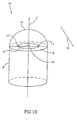
- a three dimensional representation of the optical system 10 of Fig. 1A, is shown in Fig 1B.
- FIG. 1B In the optical system 10 shown in Fig. 1B plane B, formed along line B from Fig. 1A, is shown. Axis C is perpendicular to plane B. The shape on plane B which is defined by optical window 14, encompasses focal curve D.
- a plurality of illumination elements such as 11 and 11', may be positioned on focal curve D to enable a uniform spatial illumination, though it should be appreciated that any number of illuminating elements can be used according to specific requirements of the system.
- Receiving means 13 is positioned at a point which is on, or in the vicinity of, axis C, essentially at an equal distance from both illuminating elements 11 and 11', and on, or in the vicinity of plane B, such that it receives incident light remitted from target 15. All the light radiated from illuminating elements 11 and 11' that is internally reflected from the optical window surfaces is received at points on focal curve D and is not incident on receiving means 13.
- Fig 2A illustrates a swallowable capsule which includes a) a camera system, b) an optical system for imaging an area of interest onto the camera system and c) a transmitter which transmits the video output of the camera system.
- a swallowable capsule is disclosed in US 5,604,531 , assigned to the common assignees of the present application, which is hereby incorporated by reference.
- the swallowable capsule can pass through the entire digestive tract and thus, operates as an autonomous video endoscope.
- the capsule, generally referenced 20 is shaped as an ellipsoid.
- the capsule 20 comprises a housing unit 21 and a viewing unit 23, for viewing a target point 29 on the digestive tract wall.
- the viewing unit 23 comprises an optical system according to the invention.
- the optical system comprises a protective optical window 24, preferably made of isoplast, two illumination elements 25 and 27 and an imaging device 28.
- Illumination elements 25 and 27 are positioned on a focal plane perpendicular to the axis of symmetry of the ellipsoid defined by the body of the capsule 20.
- the imaging device 28, such as a camera, is positioned on the axis of symmetry of the capsule 20.
- protective optical window 24 being a single and complete unit, is easily disposable, and can be smoothly replaced between different passes through the digestive tract. This fact, which is not affordable by endoscopes described in the art, contributes to the sterile and facile use of a diagnostic device comprising the optical system of the invention.
- the present invention provides a simply assembled diagnostic device which can obtain data, essentially free of noise such as backscatter and stray light.
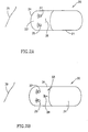
- Fig. 2B illustrates a vehicle, such as a submarine, generally referenced 30.
- Submarine 30 is shaped such that its eccentricity is equal to or larger than zero and smaller than 1.
- the submarine 30 comprises a propulsion unit 31 and a viewing cell 33, encased by window 34, in which an operator or a monitoring device 38 are positioned on the axis of symmetry of the shape of submarine 30.
- a target of interest 39 in the deep waters, is being viewed.
- the target of interest 39 is illuminated by illumination elements 35 and 37 that are positioned on a focal plane of the shape defined by the body of the submarine 30, such that light rays internally reflected from window 34 do not blind the operator and/or are not received by monitoring device 38.
Abstract
Description
- The present invention relates to an optical system for illuminating and viewing a target.
- An optical system for illuminating and viewing a target, which comprises a target, a source of illumination of the target and means for receiving the light remitted from the target, can be defined by an illumination axis and optical axis that converge at the target.
- Such an optical system may be as simple as an operator of an illumination source viewing a target, wherein the operator embodies the means for receiving the light remitted from the target. An example of such an optical system is an operator of a vehicle, that is inside the vehicle and is looking out at an illuminated target such as a road or tunnel walls.
- More complex optical systems include automated processors as means for receiving the light remitted from a viewed target. Examples of such optical systems can be found in diagnostic apparatuses such as endoscope devices. The endoscopes described in the art comprise an image pickup element and an illuminating element for illuminating an examined target.
- For these optical systems it is advantageous to have the illuminating element and receiving means contained within a single compartment, namely behind a single optical window.
- In a vehicle carrying an operator, the illuminating elements are usually situated outside the vehicle, thereby requiring the operator to leave the vehicle for repairs or the like. In vehicles such as submarines or trains travelling in a dark tunnel, this may be a perilous task.
- In diagnostic apparatuses, especially those meant to be inserted into body orifices, having a single optical window is advisable for hygienic and practical considerations.
- A frequent problem encountered in having the illumination element and means for receiving remitted light contained behind a single optical window is the "noise" (backscatter and stray light) produced by light remitted from the optical window itself, which is received by the receiving means.
- Presently used techniques for reducing noise include utilizing light guiding means, or separating the illumination element from the receiving means.
- For example,
US 5,840,014 (Miyano et al. ) describes an endoscope having an illumination window and a viewing window having a detachable protective covering and a transparent material for purging air from the space between the front end and the detachable covering, for lowering loss in illumination light quantity. - The present invention provides an optical system for illuminating and viewing a target in which an illumination element and a receiving means are disposed behind a single optical window, and which obtains data essentially free of backscatter and stray light.
- The optical system according to the present invention comprises at least one illumination element and at least one receiving means, both disposed behind a single optical window having a plurality of reflecting surfaces.
- The optical window is configured such that it defines a shape having at least one focal curve.
- At least one illumination element and at least one receiving means are geometrically positioned on the focal curve plane or in proximity of the focal curve plane, such that, when illuminating, rays from the illumination elements, that are internally reflected from the optical window surfaces, will not be incident on the receiving means.
- It will be appreciated that the term "receiving means" relates to any means suitable for receiving, processing or further transmitting illumination rays remitted from a target or data derived from these rays.
- In an embodiment of the invention the optical window is an ellipsoid shaped dome. A plurality of illumination elements are positioned on the ellipsoid focal curve and a receiving means is positioned on the axis of symmetry of the ellipsoid at an equal distance from the illumination elements.
- The components of the system, thus positioned, ensure that when illuminating, all the light internally reflected from the optical window surfaces is received at points on the focal curve and is not incident on the receiving means.
- The present invention further provides a diagnostic instrument comprising an optical system according to the present invention.
- The present invention will be understood and appreciated more fully from the following detailed description taken in conjunction with the figures in which:
- Figures 1A and 1B are schematic two and three dimensional illustrations, respectively, of an optical system according to the present invention; and
- Figures 2A and 2B are schematic illustrations of two embodiments comprising the optical system of the present invention; a diagnostic device and a vehicle carrying receiving means, respectively.
- The present invention relates to an optical system based on geometrically positioning both illumination elements and means for receiving light behind a single optical window, such that internally reflected light from the optical window will not be incident on the receiving means.
- The optical window, which is made of any suitable glass or plastic, can be viewed as being assembled from infinitesimal level surfaces, each level surface internally reflecting an illumination ray incident on it at a reflection angle equal to the angle of incidence. The level surfaces are angled to each other such that reflected illumination rays are always converged at a single known point.
- This assembly can result in a shape having focal points (for example, an ellipse) and an optical window thus assembled would have the optical property that light rays emitted from one focal point, which are internally reflected, will be propagated to the second focal point. In a three dimensional shape (such as an ellipsoid) light rays emitted from a point on a focal curve, which are internally reflected, will be propagated to another point on the focal curve.
- For example, in the field of arc lamp systems this property is used to collect energy efficiently. For example in Model A -1010 and A - 1010B lamp housings provided by Photon Technology International of New Jersey, USA, an arc source is located at a foci of an ellipsoid reflector and the radiation is reflected to another foci. Energy is collected efficiently since the light is brought to a focus by reflection rather than by refraction (through a lens) such that there is no loss due to absorption or lens surface back reflection.
- In the optical system of the present invention the illumination elements are positioned on focal points and the receiving means' position does not coincide with the focal points, thus ensuring that internally reflected light is propagated to focal points and not received by the receiving means.
- Reference is now made to Fig. 1A which is a schematic two dimensional presentation of an optical system according to the present invention.
- Fig. 1A is a two dimensional illustration of an optical system generally referenced 10. The
optical system 10 comprises anillumination element 11 andreceiving means 13, both disposed behind anoptical window 14, forviewing target 15.Optical window 14 has a surface configured such that a shape defined by it and by broken line A has an axis of symmetry B and twofocal points Illumination element 11 is positioned onfocal point 19 and receivingmeans 13 is positioned on the axis of symmetry B not coinciding with eitherfocal point - The course of light rays emitted from
illumination element 11 will be followed as an example of the behavior of illumination rays in the optical system of the invention.Light 16 is emitted from illumination element 11 (which element's position coincides with focal point 19) forilluminating target 15. A certain percent of the light (represented by ray 17) is internally reflected from theoptical window 14surfaces 14' and 14" and is propagated to the secondfocal point 12. A percent of the light 16 (represented by ray 18) is incident ontarget 15, is reflected fromtarget 15 and received by receivingmeans 13. - Thus, internally reflected light rays (such as ray 17) are propagated to areas outside the
receiving means 13 area. -
Receiving means 13 is also unexposed to direct illumination fromillumination element 11.Illumination element 11 may illuminatelight 16 in a circular band that is tangent to line B. In this case, if receivingmeans 13 is positioned on line B it will not receive any direct illumination rays fromillumination element 11. Altematively, receivingelement 13 can be concealed in a niche 13' to avoid receiving direct illumination rays fromillumination element 11. - Thus, geometric positioning of the components of the system ensures that no backscatter, such as
ray 17, and no direct light, only incident light, such asray 18, is received by receivingmeans 13. - In actuality, the
optical window 14 is a three dimensional shape. A three dimensional representation of theoptical system 10 of Fig. 1A, is shown in Fig 1B. - In the
optical system 10 shown in Fig. 1B plane B, formed along line B from Fig. 1A, is shown. Axis C is perpendicular to plane B. The shape on plane B which is defined byoptical window 14, encompasses focal curve D. - A plurality of illumination elements, such as 11 and 11', may be positioned on focal curve D to enable a uniform spatial illumination, though it should be appreciated that any number of illuminating elements can be used according to specific requirements of the system.
- Receiving means 13 is positioned at a point which is on, or in the vicinity of, axis C, essentially at an equal distance from both illuminating
elements 11 and 11', and on, or in the vicinity of plane B, such that it receives incident light remitted fromtarget 15. All the light radiated from illuminatingelements 11 and 11' that is internally reflected from the optical window surfaces is received at points on focal curve D and is not incident on receivingmeans 13. - Thus data obtained by receiving
means 13 is essentially free of backscatter and stray light. - Two of the possible applications for the optical system of the present invention are provided as two different embodiments, illustrated in Figs. 2A and 2B.
- Fig 2A illustrates a swallowable capsule which includes a) a camera system, b) an optical system for imaging an area of interest onto the camera system and c) a transmitter which transmits the video output of the camera system. Such a swallowable capsule is disclosed in
US 5,604,531 , assigned to the common assignees of the present application, which is hereby incorporated by reference. The swallowable capsule can pass through the entire digestive tract and thus, operates as an autonomous video endoscope. - The capsule, generally referenced 20 is shaped as an ellipsoid. The
capsule 20 comprises ahousing unit 21 and aviewing unit 23, for viewing atarget point 29 on the digestive tract wall. Theviewing unit 23 comprises an optical system according to the invention. - The optical system comprises a protective
optical window 24, preferably made of isoplast, twoillumination elements imaging device 28.Illumination elements capsule 20. Theimaging device 28, such as a camera, is positioned on the axis of symmetry of thecapsule 20. - Light rays emitted from
illumination elements target point 29 on the digestive tract wall are reflected toimaging device 28, whereas light rays internally reflected from protectiveoptical window 24 are propagated to points on the focal curve and not toimaging device 28. - It will be appreciated that protective
optical window 24, being a single and complete unit, is easily disposable, and can be smoothly replaced between different passes through the digestive tract. This fact, which is not affordable by endoscopes described in the art, contributes to the sterile and facile use of a diagnostic device comprising the optical system of the invention. - Thus, the present invention provides a simply assembled diagnostic device which can obtain data, essentially free of noise such as backscatter and stray light.
- Fig. 2B illustrates a vehicle, such as a submarine, generally referenced 30.
Submarine 30 is shaped such that its eccentricity is equal to or larger than zero and smaller than 1. - The
submarine 30 comprises apropulsion unit 31 and a viewing cell 33, encased bywindow 34, in which an operator or a monitoring device 38 are positioned on the axis of symmetry of the shape ofsubmarine 30. A target ofinterest 39, in the deep waters, is being viewed. The target ofinterest 39 is illuminated byillumination elements submarine 30, such that light rays internally reflected fromwindow 34 do not blind the operator and/or are not received by monitoring device 38. - Further Embodiments:
- E1. An optical system comprising at least one illumination element and at least one receiving means, both disposed behind a single optical window, having a plurality of reflecting surfaces, wherein
said optical window is configured such that it defines a shape having at least one focal curve; and
wherein at least one illumination element and at least one receiving means are positioned in proximity of the focal curve plane, such that, when illuminating, rays from the illumination element, that are internally reflected from the optical window surfaces, will not be incident on the receiving means. - E2. The optical system according to E1 wherein the at least one illumination element is positioned on the focal curve.
- E3. The optical system according to E1 wherein the receiving means is positioned on the focal curve plane but not in vicinity of the focal curve.
- E4. The optical system according to E1 wherein the illumination element illuminates a target on the opposite side of the optical window and wherein illumination rays remitted from the target are received by the receiving means.
- E5. The system according to E1 wherein the shape defined by the optical window is an ellipsoid.
- E6. A diagnostic device comprising an optical system according to E1.
- E7. A diagnostic device comprising an optical system according to E5.
- E8. A diagnostic device according to E6 wherein the device is an endoscope.
- E9. A diagnostic device according to E7 wherein the device is an endoscope.
- E10. Use of an optical system according to E1 for viewing a target outside the optical window of the optical system.
- E11. A diagnostic device according to E6 wherein the device is a swallowable capsule which comprises a system for imaging the digestive tract and a transmitter which transmits the output of the imaging system wherein the system for imaging the digestive tract comprises the receiving means.
- E12. A diagnostic device according to E7 wherein the device is a swallowable capsule which comprises a system for imaging the digestive tract and a transmitter which transmits the output of the imaging system wherein the system for imaging the digestive tract comprises the receiving means.
Claims (8)
- An optical system for a swallowable capsule, the optical system comprising an illumination element and a receiving means, the illumination element and receiving means both for being disposed behind a single optical window, said receiving means being concealed in a niche to avoid receiving direct illumination from the illumination element.
- The optical system according to claim 1 comprising a plurality of illumination elements.
- The optical system according to claim 2 wherein the receiving means is positioned at an essentially equal distance from each of the plurality of illumination elements.
- The optical system according to claim 1 wherein the receiving means is positioned on an axis of symmetry of the swallowable capsule.
- A swallowable capsule comprising a camera system, a single optical window and the optical system according to one of claims 1 to 4 disposed behind said single optical window for imaging an area of interest onto the camera system.
- The swallowable capsule according to claim 5 further comprising a transmitter for transmitting output of the camera system.
- The swallowable capsule according to claim 5 wherein the area of interest is in a gastrointestinal tract.
- The swallowable capsule according to claim 5 wherein the optical window is made of isoplast.
Applications Claiming Priority (3)
| Application Number | Priority Date | Filing Date | Title |
|---|---|---|---|
| IL13048699A IL130486A (en) | 1999-06-15 | 1999-06-15 | Optical system |
| EP00937157A EP1199975B1 (en) | 1999-06-15 | 2000-06-15 | An optical system |
| EP05026710A EP1637917A1 (en) | 1999-06-15 | 2000-06-15 | An optical system |
Related Parent Applications (1)
| Application Number | Title | Priority Date | Filing Date |
|---|---|---|---|
| EP05026710A Division EP1637917A1 (en) | 1999-06-15 | 2000-06-15 | An optical system |
Publications (2)
| Publication Number | Publication Date |
|---|---|
| EP1741382A1 true EP1741382A1 (en) | 2007-01-10 |
| EP1741382B1 EP1741382B1 (en) | 2008-09-17 |
Family
ID=11072929
Family Applications (3)
| Application Number | Title | Priority Date | Filing Date |
|---|---|---|---|
| EP05026710A Ceased EP1637917A1 (en) | 1999-06-15 | 2000-06-15 | An optical system |
| EP00937157A Expired - Lifetime EP1199975B1 (en) | 1999-06-15 | 2000-06-15 | An optical system |
| EP06022666A Expired - Lifetime EP1741382B1 (en) | 1999-06-15 | 2000-06-15 | An optical system for a swallowable capsule |
Family Applications Before (2)
| Application Number | Title | Priority Date | Filing Date |
|---|---|---|---|
| EP05026710A Ceased EP1637917A1 (en) | 1999-06-15 | 2000-06-15 | An optical system |
| EP00937157A Expired - Lifetime EP1199975B1 (en) | 1999-06-15 | 2000-06-15 | An optical system |
Country Status (9)
| Country | Link |
|---|---|
| US (4) | US6836377B1 (en) |
| EP (3) | EP1637917A1 (en) |
| JP (3) | JP3795393B2 (en) |
| AT (2) | ATE408367T1 (en) |
| AU (1) | AU5244100A (en) |
| DE (2) | DE60026025T2 (en) |
| ES (1) | ES2257299T3 (en) |
| IL (1) | IL130486A (en) |
| WO (1) | WO2000076391A1 (en) |
Cited By (2)
| Publication number | Priority date | Publication date | Assignee | Title |
|---|---|---|---|---|
| WO2008115576A1 (en) * | 2007-03-22 | 2008-09-25 | Maquet Cardiovascular Llc | Methods and devices for viewing anatomic structure |
| EP2145577A1 (en) * | 2008-07-14 | 2010-01-20 | Given Imaging Ltd. | Device and method for uniform in vivo illumination |
Families Citing this family (83)
| Publication number | Priority date | Publication date | Assignee | Title |
|---|---|---|---|---|
| MD970240A (en) * | 1997-08-29 | 1999-06-30 | Николае Павел КОВАЛЕНКО | Optical radiation photodetector |
| US10973397B2 (en) | 1999-03-01 | 2021-04-13 | West View Research, Llc | Computerized information collection and processing apparatus |
| US7914442B1 (en) | 1999-03-01 | 2011-03-29 | Gazdzinski Robert F | Endoscopic smart probe and method |
| US8068897B1 (en) | 1999-03-01 | 2011-11-29 | Gazdzinski Robert F | Endoscopic smart probe and method |
| US8636648B2 (en) | 1999-03-01 | 2014-01-28 | West View Research, Llc | Endoscopic smart probe |
| US8229549B2 (en) | 2004-07-09 | 2012-07-24 | Tyco Healthcare Group Lp | Surgical imaging device |
| US8065155B1 (en) | 1999-06-10 | 2011-11-22 | Gazdzinski Robert F | Adaptive advertising apparatus and methods |
| IL130486A (en) * | 1999-06-15 | 2005-08-31 | Given Imaging Ltd | Optical system |
| US7996067B2 (en) * | 1999-06-15 | 2011-08-09 | Given Imaging Ltd. | In-vivo imaging device, optical system and method |
| US7813789B2 (en) | 1999-06-15 | 2010-10-12 | Given Imaging Ltd. | In-vivo imaging device, optical system and method |
| IL143258A0 (en) * | 2001-05-20 | 2002-04-21 | Given Imaging Ltd | A method for in vivo imaging of the gastrointestinal tract in unmodified conditions |
| IL132944A (en) | 1999-11-15 | 2009-05-04 | Arkady Glukhovsky | Method for activating an image collecting process |
| KR100800040B1 (en) | 2000-03-08 | 2008-01-31 | 기븐 이미징 리미티드 | A capsule for in vivo imaging |
| US7553276B2 (en) | 2001-01-16 | 2009-06-30 | Given Imaging Ltd. | Method and device for imaging body lumens |
| DE60228266D1 (en) | 2001-06-18 | 2008-09-25 | Given Imaging Ltd | SWITCHABLE IN VIVO CAPSULE WITH A RIGID AND FLEXIBLE SECTION CIRCUIT BOARD |
| US6939292B2 (en) * | 2001-06-20 | 2005-09-06 | Olympus Corporation | Capsule type endoscope |
| US9113846B2 (en) | 2001-07-26 | 2015-08-25 | Given Imaging Ltd. | In-vivo imaging device providing data compression |
| US9149175B2 (en) | 2001-07-26 | 2015-10-06 | Given Imaging Ltd. | Apparatus and method for light control in an in-vivo imaging device |
| IL160179A0 (en) | 2001-08-02 | 2004-07-25 | Given Imaging Ltd | Apparatus and methods for in vivo imaging |
| US6866626B2 (en) | 2001-11-09 | 2005-03-15 | Ethicon-Endo Surgery, Inc. | Self-propelled, intraluminal device with working channel and method of use |
| ATE500777T1 (en) | 2002-01-30 | 2011-03-15 | Tyco Healthcare | SURGICAL IMAGING DEVICE |
| JP3895618B2 (en) | 2002-03-08 | 2007-03-22 | オリンパス株式会社 | Capsule endoscope |
| JP2003260025A (en) | 2002-03-08 | 2003-09-16 | Olympus Optical Co Ltd | Capsule endoscope |
| JP4363843B2 (en) | 2002-03-08 | 2009-11-11 | オリンパス株式会社 | Capsule endoscope |
| JP4009473B2 (en) | 2002-03-08 | 2007-11-14 | オリンパス株式会社 | Capsule endoscope |
| US7662094B2 (en) | 2002-05-14 | 2010-02-16 | Given Imaging Ltd. | Optical head assembly with dome, and device for use thereof |
| US20040199052A1 (en) | 2003-04-01 | 2004-10-07 | Scimed Life Systems, Inc. | Endoscopic imaging system |
| US7591783B2 (en) | 2003-04-01 | 2009-09-22 | Boston Scientific Scimed, Inc. | Articulation joint for video endoscope |
| US8118732B2 (en) | 2003-04-01 | 2012-02-21 | Boston Scientific Scimed, Inc. | Force feedback control system for video endoscope |
| US20050245789A1 (en) | 2003-04-01 | 2005-11-03 | Boston Scientific Scimed, Inc. | Fluid manifold for endoscope system |
| US7578786B2 (en) | 2003-04-01 | 2009-08-25 | Boston Scientific Scimed, Inc. | Video endoscope |
| WO2004096028A1 (en) | 2003-04-25 | 2004-11-11 | Olympus Corporation | Capsule endoscope and capsule endoscope system |
| CN100431475C (en) * | 2003-04-25 | 2008-11-12 | 奥林巴斯株式会社 | Device, method and program for image processing |
| JP3810381B2 (en) | 2003-04-25 | 2006-08-16 | オリンパス株式会社 | Image display device, image display method, and image display program |
| JP2004350963A (en) * | 2003-05-29 | 2004-12-16 | Olympus Corp | Capsule type medical treatment apparatus |
| US7427024B1 (en) | 2003-12-17 | 2008-09-23 | Gazdzinski Mark J | Chattel management apparatus and methods |
| US8639314B2 (en) | 2003-12-24 | 2014-01-28 | Given Imaging Ltd. | Device, system and method for in-vivo imaging of a body lumen |
| JP2005205077A (en) * | 2004-01-26 | 2005-08-04 | Olympus Corp | Capsule type endoscope |
| CN2715696Y (en) * | 2004-02-07 | 2005-08-10 | 姜克让 | Capsule endoscope |
| US7605852B2 (en) | 2004-05-17 | 2009-10-20 | Micron Technology, Inc. | Real-time exposure control for automatic light control |
| WO2006005075A2 (en) * | 2004-06-30 | 2006-01-12 | Amir Belson | Apparatus and methods for capsule endoscopy of the esophagus |
| JP4589048B2 (en) | 2004-08-04 | 2010-12-01 | オリンパス株式会社 | Capsule endoscope |
| WO2006039267A2 (en) | 2004-09-30 | 2006-04-13 | Boston Scientific Scimed, Inc. | Multi-functional endoscopic system for use in electrosurgical applications |
| US7479106B2 (en) | 2004-09-30 | 2009-01-20 | Boston Scientific Scimed, Inc. | Automated control of irrigation and aspiration in a single-use endoscope |
| EP1799095A2 (en) | 2004-09-30 | 2007-06-27 | Boston Scientific Scimed, Inc. | Adapter for use with digital imaging medical device |
| WO2006039511A2 (en) | 2004-09-30 | 2006-04-13 | Boston Scientific Scimed, Inc. | System and method of obstruction removal |
| US7241263B2 (en) | 2004-09-30 | 2007-07-10 | Scimed Life Systems, Inc. | Selectively rotatable shaft coupler |
| US8083671B2 (en) | 2004-09-30 | 2011-12-27 | Boston Scientific Scimed, Inc. | Fluid delivery system for use with an endoscope |
| US8097003B2 (en) | 2005-05-13 | 2012-01-17 | Boston Scientific Scimed, Inc. | Endoscopic apparatus with integrated variceal ligation device |
| US7846107B2 (en) | 2005-05-13 | 2010-12-07 | Boston Scientific Scimed, Inc. | Endoscopic apparatus with integrated multiple biopsy device |
| JP4528216B2 (en) * | 2005-06-29 | 2010-08-18 | オリンパスメディカルシステムズ株式会社 | Endoscope |
| IL177045A (en) | 2005-07-25 | 2012-12-31 | Daniel Gat | Device, system and method of receiving and recording and displaying in-vivo data with user entered data |
| US8052597B2 (en) | 2005-08-30 | 2011-11-08 | Boston Scientific Scimed, Inc. | Method for forming an endoscope articulation joint |
| US9320417B2 (en) | 2005-12-29 | 2016-04-26 | Given Imaging Ltd. | In-vivo optical imaging device with backscatter blocking |
| US20070156051A1 (en) * | 2005-12-29 | 2007-07-05 | Amit Pascal | Device and method for in-vivo illumination |
| US20070167834A1 (en) * | 2005-12-29 | 2007-07-19 | Amit Pascal | In-vivo imaging optical device and method |
| US8773500B2 (en) * | 2006-01-18 | 2014-07-08 | Capso Vision, Inc. | In vivo image capturing system including capsule enclosing a camera |
| US7967759B2 (en) | 2006-01-19 | 2011-06-28 | Boston Scientific Scimed, Inc. | Endoscopic system with integrated patient respiratory status indicator |
| US20070255098A1 (en) * | 2006-01-19 | 2007-11-01 | Capso Vision, Inc. | System and method for in vivo imager with stabilizer |
| US8888684B2 (en) | 2006-03-27 | 2014-11-18 | Boston Scientific Scimed, Inc. | Medical devices with local drug delivery capabilities |
| US7955255B2 (en) | 2006-04-20 | 2011-06-07 | Boston Scientific Scimed, Inc. | Imaging assembly with transparent distal cap |
| US8202265B2 (en) | 2006-04-20 | 2012-06-19 | Boston Scientific Scimed, Inc. | Multiple lumen assembly for use in endoscopes or other medical devices |
| WO2007125918A1 (en) | 2006-04-25 | 2007-11-08 | Olympus Medical Systems Corp. | Encapsulated endoscope |
| US8588887B2 (en) | 2006-09-06 | 2013-11-19 | Innurvation, Inc. | Ingestible low power sensor device and system for communicating with same |
| US8615284B2 (en) | 2006-09-06 | 2013-12-24 | Innurvation, Inc. | Method for acoustic information exchange involving an ingestible low power capsule |
| US8529441B2 (en) | 2008-02-12 | 2013-09-10 | Innurvation, Inc. | Ingestible endoscopic optical scanning device |
| US20100016662A1 (en) * | 2008-02-21 | 2010-01-21 | Innurvation, Inc. | Radial Scanner Imaging System |
| US8094321B2 (en) * | 2008-02-26 | 2012-01-10 | Caterpillar Inc. | Photogrammetric target and related method |
| US8636653B2 (en) | 2008-06-09 | 2014-01-28 | Capso Vision, Inc. | In vivo camera with multiple sources to illuminate tissue at different distances |
| WO2010005571A2 (en) | 2008-07-09 | 2010-01-14 | Innurvation, Inc. | Displaying image data from a scanner capsule |
| US7931149B2 (en) | 2009-05-27 | 2011-04-26 | Given Imaging Ltd. | System for storing and activating an in vivo imaging capsule |
| US8516691B2 (en) | 2009-06-24 | 2013-08-27 | Given Imaging Ltd. | Method of assembly of an in vivo imaging device with a flexible circuit board |
| US8647259B2 (en) | 2010-03-26 | 2014-02-11 | Innurvation, Inc. | Ultrasound scanning capsule endoscope (USCE) |
| KR102603702B1 (en) | 2011-02-16 | 2023-11-16 | 더 제너럴 하스피탈 코포레이션 | Optical coupler for an endoscope |
| WO2013118399A1 (en) * | 2012-02-10 | 2013-08-15 | オリンパスメディカルシステムズ株式会社 | Bio-optical measurement device and measurement probe |
| EP3725234A1 (en) | 2012-02-17 | 2020-10-21 | Progenity, Inc. | Ingestible medical device |
| US9459442B2 (en) | 2014-09-23 | 2016-10-04 | Scott Miller | Optical coupler for optical imaging visualization device |
| CN107430318B (en) * | 2015-03-31 | 2020-03-24 | 富士胶片株式会社 | Ball camera and ball cover |
| US10548467B2 (en) | 2015-06-02 | 2020-02-04 | GI Scientific, LLC | Conductive optical element |
| WO2017015480A1 (en) | 2015-07-21 | 2017-01-26 | GI Scientific, LLC | Endoscope accessory with angularly adjustable exit portal |
| US10402992B2 (en) * | 2015-10-16 | 2019-09-03 | Capsovision Inc. | Method and apparatus for endoscope with distance measuring for object scaling |
| WO2018207254A1 (en) * | 2017-05-09 | 2018-11-15 | オリンパス株式会社 | Capsule-type endoscope |
| EP3883635A1 (en) | 2018-11-19 | 2021-09-29 | Progenity, Inc. | Methods and devices for treating a disease with biotherapeutics |
Citations (6)
| Publication number | Priority date | Publication date | Assignee | Title |
|---|---|---|---|---|
| DE3928515A1 (en) * | 1988-12-20 | 1990-06-21 | Medizin Labortechnik Veb K | Endoscope esp. flexible blood vessel endoscope - achieves reduced dia. using bundled fibre conductors and objective made of individual elements |
| DE9016829U1 (en) * | 1990-12-13 | 1991-02-28 | Aesculap Ag, 7200 Tuttlingen, De | |
| JPH03264037A (en) * | 1990-03-14 | 1991-11-25 | Machida Endscope Co Ltd | Protecting device for endoscope |
| EP0667115A1 (en) * | 1994-01-17 | 1995-08-16 | State Of Israel - Ministry Of Defence | An "in vivo" video camera system |
| US5718663A (en) * | 1995-07-17 | 1998-02-17 | Olympus Winter & Ibe Gmbh | Endoscope optical system with a window plate having a light screen |
| US5840014A (en) | 1997-01-14 | 1998-11-24 | Fuji Photo Optical Co., Ltd. | Endoscope |
Family Cites Families (98)
| Publication number | Priority date | Publication date | Assignee | Title |
|---|---|---|---|---|
| DE323006C (en) * | 1918-08-04 | 1920-07-15 | Paul Hoegner | Double reflector |
| US3289779A (en) | 1965-02-01 | 1966-12-06 | Westinghouse Air Brake Co | Mobile rock drill carrier suspension system |
| US3683389A (en) | 1971-01-20 | 1972-08-08 | Corning Glass Works | Omnidirectional loop antenna array |
| US3745325A (en) * | 1971-08-17 | 1973-07-10 | Eastman Kodak Co | Photographic light |
| US3971362A (en) | 1972-10-27 | 1976-07-27 | The United States Of America As Represented By The Administrator Of The National Aeronautics And Space Administration | Miniature ingestible telemeter devices to measure deep-body temperature |
| US4027510A (en) | 1974-05-15 | 1977-06-07 | Siegfried Hiltebrandt | Forceps |
| US4005287A (en) * | 1975-07-28 | 1977-01-25 | Recognition Equipment Incorporated | Nose attachment for OCR wand |
| US4017163A (en) * | 1976-04-16 | 1977-04-12 | The United States Of America As Represented By The United States Energy Research And Development Administration | Angle amplifying optics using plane and ellipsoidal reflectors |
| US4239040A (en) | 1976-10-19 | 1980-12-16 | Kabushiki Kaisha Daini Seikosha | Capsule for medical use |
| JPS5394515A (en) | 1977-01-31 | 1978-08-18 | Kubota Ltd | Method of producing glass fiber reinforced cement plate |
| JPS5479581A (en) * | 1977-12-07 | 1979-06-25 | Seiko Instr & Electronics Ltd | Thickness-width slide crystal vibrator |
| US4177800A (en) | 1978-04-10 | 1979-12-11 | Enger Carl C | Implantable biotelemetry transmitter and method of using same |
| US4234912A (en) * | 1978-06-28 | 1980-11-18 | International Telephone And Telegraph Corporation | Luminaire for residential roadway lighting |
| JPS5519124A (en) | 1978-07-27 | 1980-02-09 | Olympus Optical Co | Camera system for medical treatment |
| US4217045A (en) | 1978-12-29 | 1980-08-12 | Ziskind Stanley H | Capsule for photographic use in a walled organ of the living body |
| JPS5745833A (en) | 1980-09-01 | 1982-03-16 | Taeko Nakagawa | Stomack camera |
| US5993378A (en) | 1980-10-28 | 1999-11-30 | Lemelson; Jerome H. | Electro-optical instruments and methods for treating disease |
| JPS57156736A (en) | 1981-03-23 | 1982-09-28 | Olympus Optical Co | Therapeutic capsule apparatus |
| US4491865A (en) | 1982-09-29 | 1985-01-01 | Welch Allyn, Inc. | Image sensor assembly |
| DE3337455A1 (en) | 1982-10-15 | 1984-04-19 | Olympus Optical Co., Ltd., Tokio/Tokyo | ENDOSCOPIC PHOTOGRAPHER |
| US4596050A (en) * | 1984-04-26 | 1986-06-17 | Rogers Gordon W | Information processing system using optically encoded signals |
| DE3440177A1 (en) | 1984-11-02 | 1986-05-15 | Friedrich Dipl.-Ing. 8031 Eichenau Hilliges | Television recording and replay device for endoscopy on human and animal bodies |
| US4689621A (en) | 1986-03-31 | 1987-08-25 | The United States Of America As Represented By The Administrator Of The National Aeronautics And Space Administration | Temperature responsive transmitter |
| JPH0664243B2 (en) | 1986-04-30 | 1994-08-22 | オリンパス光学工業株式会社 | Endoscope |
| JPS6349125A (en) | 1986-08-16 | 1988-03-01 | 奥津 一郎 | Guide pipe for endoscope |
| US4735214A (en) | 1986-09-05 | 1988-04-05 | Berman Irwin R | Gastrointestinal diagnostic capsule and method of use |
| JPH07104493B2 (en) | 1987-02-17 | 1995-11-13 | オリンパス光学工業株式会社 | Endoscope device |
| US4917097A (en) | 1987-10-27 | 1990-04-17 | Endosonics Corporation | Apparatus and method for imaging small cavities |
| JP2693978B2 (en) | 1988-02-26 | 1997-12-24 | オリンパス光学工業株式会社 | Electronic endoscope device |
| US4936823A (en) | 1988-05-04 | 1990-06-26 | Triangle Research And Development Corp. | Transendoscopic implant capsule |
| US4844076A (en) | 1988-08-26 | 1989-07-04 | The Johns Hopkins University | Ingestible size continuously transmitting temperature monitoring pill |
| US5010412A (en) | 1988-12-27 | 1991-04-23 | The Boeing Company | High frequency, low power light source for video camera |
| DE3921233A1 (en) | 1989-06-28 | 1991-02-14 | Storz Karl Gmbh & Co | ENDOSCOPE WITH A VIDEO DEVICE AT THE DISTAL END |
| US5681260A (en) * | 1989-09-22 | 1997-10-28 | Olympus Optical Co., Ltd. | Guiding apparatus for guiding an insertable body within an inspected object |
| EP0419729A1 (en) | 1989-09-29 | 1991-04-03 | Siemens Aktiengesellschaft | Position finding of a catheter by means of non-ionising fields |
| JP2579372B2 (en) | 1989-12-04 | 1997-02-05 | 日本テキサス・インスツルメンツ株式会社 | Low power imaging device |
| GB9018660D0 (en) | 1990-08-24 | 1990-10-10 | Imperial College | Probe system |
| JPH04109927A (en) | 1990-08-31 | 1992-04-10 | Toshiba Corp | Electronic endoscope apparatus |
| JPH04144533A (en) | 1990-10-05 | 1992-05-19 | Olympus Optical Co Ltd | Endoscope |
| JP3164609B2 (en) | 1990-10-31 | 2001-05-08 | オリンパス光学工業株式会社 | Endoscope device |
| JP2948900B2 (en) | 1990-11-16 | 1999-09-13 | オリンパス光学工業株式会社 | Medical capsule |
| US5267033A (en) | 1990-11-28 | 1993-11-30 | Dai Nippon Printing Co., Ltd. | Hollow body inspection system, hollow body inspection apparatus and signal transmission apparatus |
| US5217449A (en) | 1990-12-11 | 1993-06-08 | Miyarisan Kabushiki Kaisha | Medical capsule and apparatus for activating the same |
| JP2768029B2 (en) | 1991-02-19 | 1998-06-25 | 日新電機株式会社 | Digestive system diagnostic device |
| US5279607A (en) | 1991-05-30 | 1994-01-18 | The State University Of New York | Telemetry capsule and process |
| US5395366A (en) | 1991-05-30 | 1995-03-07 | The State University Of New York | Sampling capsule and process |
| US5222477A (en) | 1991-09-30 | 1993-06-29 | Welch Allyn, Inc. | Endoscope or borescope stereo viewing system |
| AT399229B (en) | 1992-04-23 | 1995-04-25 | Avl Verbrennungskraft Messtech | SENSOR ARRANGEMENT FOR DIRECT OR INDIRECT OPTICAL DETERMINATION OF PHYSICAL OR CHEMICAL PARAMETERS |
| JPH0663051A (en) | 1992-08-20 | 1994-03-08 | Olympus Optical Co Ltd | Capsule device for medical treatment |
| JP3631257B2 (en) | 1992-08-28 | 2005-03-23 | オリンパス株式会社 | Electronic endoscope device |
| US5662587A (en) | 1992-09-16 | 1997-09-02 | Cedars Sinai Medical Center | Robotic endoscopy |
| US5495114A (en) | 1992-09-30 | 1996-02-27 | Adair; Edwin L. | Miniaturized electronic imaging chip |
| US5373840A (en) | 1992-10-02 | 1994-12-20 | Knighton; David R. | Endoscope and method for vein removal |
| JPH06114037A (en) | 1992-10-05 | 1994-04-26 | Olympus Optical Co Ltd | Capsule device for medical treatment |
| US5603687A (en) | 1992-10-28 | 1997-02-18 | Oktas General Partnership | Asymmetric stereo-optic endoscope |
| JP3285235B2 (en) | 1992-11-05 | 2002-05-27 | オリンパス光学工業株式会社 | Capsule device for in vivo observation |
| JP3020376B2 (en) | 1993-03-26 | 2000-03-15 | サージミヤワキ株式会社 | Internal body identification device for animals |
| CA2145232A1 (en) | 1994-03-24 | 1995-09-25 | Arie Avny | Viewing method and apparatus particularly useful for viewing the interior of the large intestine |
| US5653677A (en) | 1994-04-12 | 1997-08-05 | Fuji Photo Optical Co. Ltd | Electronic endoscope apparatus with imaging unit separable therefrom |
| IL110475A (en) | 1994-07-27 | 2000-11-21 | Given Imaging Ltd | Optical system for flexible tubes |
| JP3862313B2 (en) | 1995-02-15 | 2006-12-27 | キヤノン株式会社 | Image heating device |
| JPH08248326A (en) | 1995-03-10 | 1996-09-27 | Olympus Optical Co Ltd | Stereoscopic endoscope |
| US5764274A (en) | 1996-02-16 | 1998-06-09 | Presstek, Inc. | Apparatus for laser-discharge imaging and focusing elements for use therewith |
| US5833603A (en) | 1996-03-13 | 1998-11-10 | Lipomatrix, Inc. | Implantable biosensing transponder |
| GB9619470D0 (en) | 1996-09-18 | 1996-10-30 | Univ London | Imaging apparatus |
| US6240312B1 (en) * | 1997-10-23 | 2001-05-29 | Robert R. Alfano | Remote-controllable, micro-scale device for use in in vivo medical diagnosis and/or treatment |
| JPH11142933A (en) | 1997-11-13 | 1999-05-28 | Takashi Kawakami | Waterproof camera |
| IL122602A0 (en) * | 1997-12-15 | 1998-08-16 | Tally Eitan Zeev Pearl And Co | Energy management of a video capsule |
| US6632171B2 (en) | 1997-12-22 | 2003-10-14 | Given Imaging Ltd. | Method for in vivo delivery of autonomous capsule |
| EP0941691A1 (en) | 1998-03-11 | 1999-09-15 | Welch Allyn, Inc. | Compact video imaging assembly |
| IL126727A (en) | 1998-10-22 | 2006-12-31 | Given Imaging Ltd | Method for delivering a device to a target location |
| US7116352B2 (en) | 1999-02-25 | 2006-10-03 | Visionsense Ltd. | Capsule |
| US8636648B2 (en) | 1999-03-01 | 2014-01-28 | West View Research, Llc | Endoscopic smart probe |
| US6612701B2 (en) * | 2001-08-20 | 2003-09-02 | Optical Products Development Corporation | Image enhancement in a real image projection system, using on-axis reflectors, at least one of which is aspheric in shape |
| IL130486A (en) * | 1999-06-15 | 2005-08-31 | Given Imaging Ltd | Optical system |
| US7996067B2 (en) | 1999-06-15 | 2011-08-09 | Given Imaging Ltd. | In-vivo imaging device, optical system and method |
| GB2352636B (en) | 1999-08-03 | 2003-05-14 | Univ College London Hospitals | Improved passage-travelling device |
| IL134017A (en) | 2000-01-13 | 2008-04-13 | Capsule View Inc | Camera for viewing inside intestines |
| US7039453B2 (en) | 2000-02-08 | 2006-05-02 | Tarun Mullick | Miniature ingestible capsule |
| KR100800040B1 (en) | 2000-03-08 | 2008-01-31 | 기븐 이미징 리미티드 | A capsule for in vivo imaging |
| US6709387B1 (en) * | 2000-05-15 | 2004-03-23 | Given Imaging Ltd. | System and method for controlling in vivo camera capture and display rate |
| WO2001089596A2 (en) | 2000-05-23 | 2001-11-29 | Given Imaging Ltd. | Device for positioning object in a body lumen |
| US6632175B1 (en) | 2000-11-08 | 2003-10-14 | Hewlett-Packard Development Company, L.P. | Swallowable data recorder capsule medical device |
| US6416181B1 (en) * | 2000-12-15 | 2002-07-09 | Eastman Kodak Company | Monocentric autostereoscopic optical apparatus and method |
| EP1399201B1 (en) | 2001-01-11 | 2012-04-11 | Given Imaging Ltd. | Device for in-vivo procedures |
| IL143259A (en) | 2001-05-20 | 2006-08-01 | Given Imaging Ltd | Method for moving an object through the colon |
| AU2002304269A1 (en) | 2001-05-20 | 2002-12-03 | Given Imaging Ltd. | A floatable in vivo sensing device |
| DE60228266D1 (en) * | 2001-06-18 | 2008-09-25 | Given Imaging Ltd | SWITCHABLE IN VIVO CAPSULE WITH A RIGID AND FLEXIBLE SECTION CIRCUIT BOARD |
| US6939292B2 (en) * | 2001-06-20 | 2005-09-06 | Olympus Corporation | Capsule type endoscope |
| JP4744026B2 (en) * | 2001-07-30 | 2011-08-10 | オリンパス株式会社 | Capsule endoscope and capsule endoscope system |
| JP3974769B2 (en) | 2001-11-06 | 2007-09-12 | オリンパス株式会社 | Capsule medical device |
| US6511182B1 (en) * | 2001-11-13 | 2003-01-28 | Eastman Kodak Company | Autostereoscopic optical apparatus using a scanned linear image source |
| JP3895618B2 (en) * | 2002-03-08 | 2007-03-22 | オリンパス株式会社 | Capsule endoscope |
| JP4009473B2 (en) * | 2002-03-08 | 2007-11-14 | オリンパス株式会社 | Capsule endoscope |
| JP4363843B2 (en) | 2002-03-08 | 2009-11-11 | オリンパス株式会社 | Capsule endoscope |
| AU2003274646A1 (en) | 2002-10-21 | 2004-05-04 | Given Imaging Ltd. | Intubation and imaging device and system |
| JP2005003828A (en) | 2003-06-10 | 2005-01-06 | Sony Corp | Hologram recording apparatus and hologram recording method |
| JP2005106614A (en) * | 2003-09-30 | 2005-04-21 | Tdk Corp | Jig for calibrating three-dimensional camera, and method for calibrating camera |
-
1999
- 1999-06-15 IL IL13048699A patent/IL130486A/en not_active IP Right Cessation
-
2000
- 2000-06-15 AU AU52441/00A patent/AU5244100A/en not_active Abandoned
- 2000-06-15 DE DE60026025T patent/DE60026025T2/en not_active Expired - Lifetime
- 2000-06-15 DE DE60040310T patent/DE60040310D1/en not_active Expired - Lifetime
- 2000-06-15 AT AT06022666T patent/ATE408367T1/en not_active IP Right Cessation
- 2000-06-15 US US10/009,837 patent/US6836377B1/en not_active Expired - Lifetime
- 2000-06-15 ES ES00937157T patent/ES2257299T3/en not_active Expired - Lifetime
- 2000-06-15 WO PCT/IL2000/000349 patent/WO2000076391A1/en active IP Right Grant
- 2000-06-15 JP JP2001502738A patent/JP3795393B2/en not_active Expired - Lifetime
- 2000-06-15 EP EP05026710A patent/EP1637917A1/en not_active Ceased
- 2000-06-15 EP EP00937157A patent/EP1199975B1/en not_active Expired - Lifetime
- 2000-06-15 EP EP06022666A patent/EP1741382B1/en not_active Expired - Lifetime
- 2000-06-15 AT AT00937157T patent/ATE317986T1/en not_active IP Right Cessation
-
2004
- 2004-06-30 US US10/879,276 patent/US6934093B2/en not_active Expired - Lifetime
-
2005
- 2005-04-27 US US11/115,320 patent/US7433133B2/en not_active Expired - Fee Related
- 2005-05-27 JP JP2005155953A patent/JP3795513B2/en not_active Expired - Lifetime
- 2005-05-30 JP JP2005003828U patent/JP3114298U/en not_active Expired - Lifetime
- 2005-12-02 US US11/291,906 patent/US7327525B2/en not_active Expired - Fee Related
Patent Citations (7)
| Publication number | Priority date | Publication date | Assignee | Title |
|---|---|---|---|---|
| DE3928515A1 (en) * | 1988-12-20 | 1990-06-21 | Medizin Labortechnik Veb K | Endoscope esp. flexible blood vessel endoscope - achieves reduced dia. using bundled fibre conductors and objective made of individual elements |
| JPH03264037A (en) * | 1990-03-14 | 1991-11-25 | Machida Endscope Co Ltd | Protecting device for endoscope |
| DE9016829U1 (en) * | 1990-12-13 | 1991-02-28 | Aesculap Ag, 7200 Tuttlingen, De | |
| EP0667115A1 (en) * | 1994-01-17 | 1995-08-16 | State Of Israel - Ministry Of Defence | An "in vivo" video camera system |
| US5604531A (en) | 1994-01-17 | 1997-02-18 | State Of Israel, Ministry Of Defense, Armament Development Authority | In vivo video camera system |
| US5718663A (en) * | 1995-07-17 | 1998-02-17 | Olympus Winter & Ibe Gmbh | Endoscope optical system with a window plate having a light screen |
| US5840014A (en) | 1997-01-14 | 1998-11-24 | Fuji Photo Optical Co., Ltd. | Endoscope |
Cited By (4)
| Publication number | Priority date | Publication date | Assignee | Title |
|---|---|---|---|---|
| WO2008115576A1 (en) * | 2007-03-22 | 2008-09-25 | Maquet Cardiovascular Llc | Methods and devices for viewing anatomic structure |
| EP2145577A1 (en) * | 2008-07-14 | 2010-01-20 | Given Imaging Ltd. | Device and method for uniform in vivo illumination |
| US8262566B2 (en) | 2008-07-14 | 2012-09-11 | Given Imaging Ltd. | Device and method for uniform in vivo illumination |
| EP2145577B1 (en) * | 2008-07-14 | 2016-01-27 | Given Imaging Ltd. | Device and method for uniform in vivo illumination |
Also Published As
| Publication number | Publication date |
|---|---|
| JP2005279292A (en) | 2005-10-13 |
| ATE408367T1 (en) | 2008-10-15 |
| JP2003501704A (en) | 2003-01-14 |
| EP1199975A1 (en) | 2002-05-02 |
| EP1199975A4 (en) | 2004-03-31 |
| DE60026025T2 (en) | 2006-09-14 |
| DE60026025D1 (en) | 2006-04-20 |
| US7327525B2 (en) | 2008-02-05 |
| JP3114298U (en) | 2005-10-27 |
| EP1741382B1 (en) | 2008-09-17 |
| EP1199975B1 (en) | 2006-02-15 |
| DE60040310D1 (en) | 2008-10-30 |
| US7433133B2 (en) | 2008-10-07 |
| US6836377B1 (en) | 2004-12-28 |
| IL130486A0 (en) | 2000-06-01 |
| US20040240077A1 (en) | 2004-12-02 |
| AU5244100A (en) | 2001-01-02 |
| US20060122461A1 (en) | 2006-06-08 |
| US20050185299A1 (en) | 2005-08-25 |
| IL130486A (en) | 2005-08-31 |
| ES2257299T3 (en) | 2006-08-01 |
| WO2000076391A1 (en) | 2000-12-21 |
| JP3795513B2 (en) | 2006-07-12 |
| US6934093B2 (en) | 2005-08-23 |
| JP3795393B2 (en) | 2006-07-12 |
| ATE317986T1 (en) | 2006-03-15 |
| EP1637917A1 (en) | 2006-03-22 |
Similar Documents
| Publication | Publication Date | Title |
|---|---|---|
| EP1199975B1 (en) | An optical system | |
| EP0100517B1 (en) | Optical fiber sensor | |
| US8496580B2 (en) | Omnidirectional and forward-looking imaging device | |
| US7813789B2 (en) | In-vivo imaging device, optical system and method | |
| EP3114983B1 (en) | Laryngoscope blade with a light collecting optical element | |
| US4957112A (en) | Ultrasonic diagnostic apparatus | |
| US7996067B2 (en) | In-vivo imaging device, optical system and method | |
| JP5189762B2 (en) | In vivo imaging optical device | |
| JP2005503702A (en) | Optical system, optical element, and user unit for illuminating a subject for imaging | |
| EP0075415A2 (en) | Endoscopes provided with perspective illumination attachments | |
| IL167233A (en) | Optical system | |
| US7033051B2 (en) | Infrared ray irradiation apparatus for night vision system | |
| JP6865305B2 (en) | Imaging optics, endoscopes and imaging devices | |
| EP3613328B1 (en) | A tip part for a vision device | |
| JP2004267255A (en) | Tip part of endoscope with jacket sheath | |
| JP2004041457A (en) | Distal end of endoscope |
Legal Events
| Date | Code | Title | Description |
|---|---|---|---|
| PUAI | Public reference made under article 153(3) epc to a published international application that has entered the european phase |
Free format text: ORIGINAL CODE: 0009012 |
|
| AC | Divisional application: reference to earlier application |
Ref document number: 1199975 Country of ref document: EP Kind code of ref document: P Ref document number: 1637917 Country of ref document: EP Kind code of ref document: P |
|
| AK | Designated contracting states |
Kind code of ref document: A1 Designated state(s): AT BE CH CY DE DK ES FI FR GB GR IE IT LI LU MC NL PT SE |
|
| 17P | Request for examination filed |
Effective date: 20070306 |
|
| RAP1 | Party data changed (applicant data changed or rights of an application transferred) |
Owner name: GIVEN IMAGING LTD. |
|
| AKX | Designation fees paid |
Designated state(s): AT BE CH CY DE DK ES FI FR GB GR IE IT LI LU MC NL PT SE |
|
| GRAP | Despatch of communication of intention to grant a patent |
Free format text: ORIGINAL CODE: EPIDOSNIGR1 |
|
| GRAS | Grant fee paid |
Free format text: ORIGINAL CODE: EPIDOSNIGR3 |
|
| GRAA | (expected) grant |
Free format text: ORIGINAL CODE: 0009210 |
|
| AC | Divisional application: reference to earlier application |
Ref document number: 1199975 Country of ref document: EP Kind code of ref document: P Ref document number: 1637917 Country of ref document: EP Kind code of ref document: P |
|
| AK | Designated contracting states |
Kind code of ref document: B1 Designated state(s): AT BE CH CY DE DK ES FI FR GB GR IE IT LI LU MC NL PT SE |
|
| REG | Reference to a national code |
Ref country code: GB Ref legal event code: FG4D |
|
| REG | Reference to a national code |
Ref country code: CH Ref legal event code: EP |
|
| REG | Reference to a national code |
Ref country code: IE Ref legal event code: FG4D |
|
| REF | Corresponds to: |
Ref document number: 60040310 Country of ref document: DE Date of ref document: 20081030 Kind code of ref document: P |
|
| PG25 | Lapsed in a contracting state [announced via postgrant information from national office to epo] |
Ref country code: AT Free format text: LAPSE BECAUSE OF FAILURE TO SUBMIT A TRANSLATION OF THE DESCRIPTION OR TO PAY THE FEE WITHIN THE PRESCRIBED TIME-LIMIT Effective date: 20080917 |
|
| NLV1 | Nl: lapsed or annulled due to failure to fulfill the requirements of art. 29p and 29m of the patents act | ||
| PG25 | Lapsed in a contracting state [announced via postgrant information from national office to epo] |
Ref country code: BE Free format text: LAPSE BECAUSE OF FAILURE TO SUBMIT A TRANSLATION OF THE DESCRIPTION OR TO PAY THE FEE WITHIN THE PRESCRIBED TIME-LIMIT Effective date: 20080917 |
|
| PG25 | Lapsed in a contracting state [announced via postgrant information from national office to epo] |
Ref country code: ES Free format text: LAPSE BECAUSE OF FAILURE TO SUBMIT A TRANSLATION OF THE DESCRIPTION OR TO PAY THE FEE WITHIN THE PRESCRIBED TIME-LIMIT Effective date: 20081228 |
|
| PG25 | Lapsed in a contracting state [announced via postgrant information from national office to epo] |
Ref country code: NL Free format text: LAPSE BECAUSE OF FAILURE TO SUBMIT A TRANSLATION OF THE DESCRIPTION OR TO PAY THE FEE WITHIN THE PRESCRIBED TIME-LIMIT Effective date: 20080917 Ref country code: PT Free format text: LAPSE BECAUSE OF FAILURE TO SUBMIT A TRANSLATION OF THE DESCRIPTION OR TO PAY THE FEE WITHIN THE PRESCRIBED TIME-LIMIT Effective date: 20090217 |
|
| PLBE | No opposition filed within time limit |
Free format text: ORIGINAL CODE: 0009261 |
|
| STAA | Information on the status of an ep patent application or granted ep patent |
Free format text: STATUS: NO OPPOSITION FILED WITHIN TIME LIMIT |
|
| PG25 | Lapsed in a contracting state [announced via postgrant information from national office to epo] |
Ref country code: DK Free format text: LAPSE BECAUSE OF FAILURE TO SUBMIT A TRANSLATION OF THE DESCRIPTION OR TO PAY THE FEE WITHIN THE PRESCRIBED TIME-LIMIT Effective date: 20080917 |
|
| 26N | No opposition filed |
Effective date: 20090618 |
|
| PG25 | Lapsed in a contracting state [announced via postgrant information from national office to epo] |
Ref country code: MC Free format text: LAPSE BECAUSE OF NON-PAYMENT OF DUE FEES Effective date: 20090630 Ref country code: SE Free format text: LAPSE BECAUSE OF FAILURE TO SUBMIT A TRANSLATION OF THE DESCRIPTION OR TO PAY THE FEE WITHIN THE PRESCRIBED TIME-LIMIT Effective date: 20081217 |
|
| REG | Reference to a national code |
Ref country code: CH Ref legal event code: PL |
|
| PG25 | Lapsed in a contracting state [announced via postgrant information from national office to epo] |
Ref country code: LI Free format text: LAPSE BECAUSE OF NON-PAYMENT OF DUE FEES Effective date: 20090630 Ref country code: IE Free format text: LAPSE BECAUSE OF NON-PAYMENT OF DUE FEES Effective date: 20090615 Ref country code: CH Free format text: LAPSE BECAUSE OF NON-PAYMENT OF DUE FEES Effective date: 20090630 |
|
| PG25 | Lapsed in a contracting state [announced via postgrant information from national office to epo] |
Ref country code: GR Free format text: LAPSE BECAUSE OF FAILURE TO SUBMIT A TRANSLATION OF THE DESCRIPTION OR TO PAY THE FEE WITHIN THE PRESCRIBED TIME-LIMIT Effective date: 20081218 |
|
| PG25 | Lapsed in a contracting state [announced via postgrant information from national office to epo] |
Ref country code: FI Free format text: LAPSE BECAUSE OF FAILURE TO SUBMIT A TRANSLATION OF THE DESCRIPTION OR TO PAY THE FEE WITHIN THE PRESCRIBED TIME-LIMIT Effective date: 20080917 |
|
| PG25 | Lapsed in a contracting state [announced via postgrant information from national office to epo] |
Ref country code: LU Free format text: LAPSE BECAUSE OF NON-PAYMENT OF DUE FEES Effective date: 20090615 |
|
| PG25 | Lapsed in a contracting state [announced via postgrant information from national office to epo] |
Ref country code: CY Free format text: LAPSE BECAUSE OF FAILURE TO SUBMIT A TRANSLATION OF THE DESCRIPTION OR TO PAY THE FEE WITHIN THE PRESCRIBED TIME-LIMIT Effective date: 20080917 |
|
| REG | Reference to a national code |
Ref country code: FR Ref legal event code: PLFP Year of fee payment: 17 |
|
| REG | Reference to a national code |
Ref country code: FR Ref legal event code: PLFP Year of fee payment: 18 |
|
| REG | Reference to a national code |
Ref country code: FR Ref legal event code: PLFP Year of fee payment: 19 |
|
| PGFP | Annual fee paid to national office [announced via postgrant information from national office to epo] |
Ref country code: IT Payment date: 20190521 Year of fee payment: 20 Ref country code: DE Payment date: 20190521 Year of fee payment: 20 |
|
| PGFP | Annual fee paid to national office [announced via postgrant information from national office to epo] |
Ref country code: FR Payment date: 20190522 Year of fee payment: 20 |
|
| PGFP | Annual fee paid to national office [announced via postgrant information from national office to epo] |
Ref country code: GB Payment date: 20190522 Year of fee payment: 20 |
|
| REG | Reference to a national code |
Ref country code: DE Ref legal event code: R071 Ref document number: 60040310 Country of ref document: DE |
|
| REG | Reference to a national code |
Ref country code: GB Ref legal event code: PE20 Expiry date: 20200614 |
|
| PG25 | Lapsed in a contracting state [announced via postgrant information from national office to epo] |
Ref country code: GB Free format text: LAPSE BECAUSE OF EXPIRATION OF PROTECTION Effective date: 20200614 |