EP1553778A1 - De-ringing filter - Google Patents
De-ringing filter Download PDFInfo
- Publication number
- EP1553778A1 EP1553778A1 EP04030974A EP04030974A EP1553778A1 EP 1553778 A1 EP1553778 A1 EP 1553778A1 EP 04030974 A EP04030974 A EP 04030974A EP 04030974 A EP04030974 A EP 04030974A EP 1553778 A1 EP1553778 A1 EP 1553778A1
- Authority
- EP
- European Patent Office
- Prior art keywords
- pixels
- pixel
- group
- image
- test
- Prior art date
- Legal status (The legal status is an assumption and is not a legal conclusion. Google has not performed a legal analysis and makes no representation as to the accuracy of the status listed.)
- Ceased
Links
Images


Classifications
-
- H—ELECTRICITY
- H04—ELECTRIC COMMUNICATION TECHNIQUE
- H04N—PICTORIAL COMMUNICATION, e.g. TELEVISION
- H04N19/00—Methods or arrangements for coding, decoding, compressing or decompressing digital video signals
- H04N19/85—Methods or arrangements for coding, decoding, compressing or decompressing digital video signals using pre-processing or post-processing specially adapted for video compression
- H04N19/86—Methods or arrangements for coding, decoding, compressing or decompressing digital video signals using pre-processing or post-processing specially adapted for video compression involving reduction of coding artifacts, e.g. of blockiness
-
- H—ELECTRICITY
- H04—ELECTRIC COMMUNICATION TECHNIQUE
- H04N—PICTORIAL COMMUNICATION, e.g. TELEVISION
- H04N19/00—Methods or arrangements for coding, decoding, compressing or decompressing digital video signals
- H04N19/10—Methods or arrangements for coding, decoding, compressing or decompressing digital video signals using adaptive coding
- H04N19/102—Methods or arrangements for coding, decoding, compressing or decompressing digital video signals using adaptive coding characterised by the element, parameter or selection affected or controlled by the adaptive coding
- H04N19/117—Filters, e.g. for pre-processing or post-processing
-
- H—ELECTRICITY
- H04—ELECTRIC COMMUNICATION TECHNIQUE
- H04N—PICTORIAL COMMUNICATION, e.g. TELEVISION
- H04N19/00—Methods or arrangements for coding, decoding, compressing or decompressing digital video signals
- H04N19/10—Methods or arrangements for coding, decoding, compressing or decompressing digital video signals using adaptive coding
- H04N19/134—Methods or arrangements for coding, decoding, compressing or decompressing digital video signals using adaptive coding characterised by the element, parameter or criterion affecting or controlling the adaptive coding
- H04N19/136—Incoming video signal characteristics or properties
- H04N19/14—Coding unit complexity, e.g. amount of activity or edge presence estimation
-
- H—ELECTRICITY
- H04—ELECTRIC COMMUNICATION TECHNIQUE
- H04N—PICTORIAL COMMUNICATION, e.g. TELEVISION
- H04N19/00—Methods or arrangements for coding, decoding, compressing or decompressing digital video signals
- H04N19/10—Methods or arrangements for coding, decoding, compressing or decompressing digital video signals using adaptive coding
- H04N19/169—Methods or arrangements for coding, decoding, compressing or decompressing digital video signals using adaptive coding characterised by the coding unit, i.e. the structural portion or semantic portion of the video signal being the object or the subject of the adaptive coding
- H04N19/182—Methods or arrangements for coding, decoding, compressing or decompressing digital video signals using adaptive coding characterised by the coding unit, i.e. the structural portion or semantic portion of the video signal being the object or the subject of the adaptive coding the unit being a pixel
-
- H—ELECTRICITY
- H04—ELECTRIC COMMUNICATION TECHNIQUE
- H04N—PICTORIAL COMMUNICATION, e.g. TELEVISION
- H04N19/00—Methods or arrangements for coding, decoding, compressing or decompressing digital video signals
- H04N19/80—Details of filtering operations specially adapted for video compression, e.g. for pixel interpolation
Definitions
- This invention generally relates to compressed image and video coding and, more particularly, to a method for filtering ringing artifacts that may occur as a result of compressed image and video encoding/decoding processes.
- Computation resources and bandwidth can be saved by encoding images and videos at a low bit-rate.
- low bit-rate encoding may result in several types of artifacts in the decompressed images.
- the most notable artifacts include blocking and ringing artifacts.
- the ringing artifacts are typically observed around the true edges of an image.
- the ringing artifacts are also referred to as mosquito artifacts, as they tend to be annoying, especially in moving images (video sequences).
- de-ringing conventional methods operate in both the transform and pixel domains.
- Other conventional de-ringing filters make use of quantization information.
- One drawback of all the above-mentioned de-ringing filters is that are computationally intensive. Thus, the filters are not suitable for all receiving systems. Further, the filters may result in unacceptable delays, even when they can be implemented.
- the present invention is a de-ringing filter with a low computational complexity.
- a decision to apply the filter is made for each pixel based on its edge strength.
- a 3x3 kernel is used for filtering. Only the non-edge neighbor pixels are used to filter the current (test) pixel.
- the filter uses all of the non-edge neighbor pixels and the current pixel weighted appropriately, based on the total number of non-edge neighbor pixels.
- the invention works entirely in the pixel domain and does not use or need any quantization information. Further, the solution is not necessarily block or macroblock-based.
- an image de-ringing filter method comprises: accepting a plurality of image pixels; collecting data from a first group of pixels neighboring a test pixel; in response to the first group data, deciding if the test pixel includes image ringing artifacts; collecting data from a second group of pixels neighboring the test pixel; in response to the second group data, generating a filtered value (FV); and, replacing the test pixel actual value with FV.
- FV filtered value
- collecting data from the first and second group of pixels includes the performance of a mathematical operation.
- a matrix may be defined for the multiplication of the first group of pixels.
- the mathematical operation may involve the comparison of pixels values on opposite sides of a coordinate axis bisecting the test pixel. More specifically, values of pixels on a first side of the coordinate axis may be subtracted from pixels on a second side of the coordinate axis, opposite of the first side. Then, the difference is compared to a threshold.
- generating a FV in response to the second group operation includes: generating a map value for each pixel in the second group; and, using pixels from the second group to calculate FV, if they are equal to a first map value. Specifics of map values and the definition of the second group are provided.
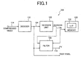
- Fig. 1 is a schematic block diagram of the present invention image de-ringing filter system.
- the system 100 comprises a decision unit 102 having an input on line 104 to accept a plurality of image pixels.
- the decision unit 102 collects data from a first group of pixels neighboring a test pixel. In response to the first group data, the decision unit 102 supplies a decision at an output on line 106 as to whether the test pixel includes image ringing artifacts.
- a filter 108 has an input on line 104 to accept the plurality of image pixels and an input on line 106 to accept the decision.
- the filter 108 collects data from a second group of pixels neighboring the test pixel. In response to the second group data, the filter generates a filtered value (FV) and supplies the FV at an output on line 110 as a replacement to the test pixel actual value.
- FV filtered value
- a decoder 112 has a connection on line 114 to accepted encoded video information.
- the encoded video may come from a network, local storage, or other source. This information may be encoded in a standard such as moving picture experts group (MPEG) or H.264 standards, to name a few examples.
- MPEG moving picture experts group
- the decoder 112 has an output on line 104 to supply the plurality of image pixels to the decision unit 102, and to the filter 108, as decoded image information.
- Fig. 2 is a diagram depicting a test pixel, and a group of neighboring pixels. Pixels from the first group are represented with a "1", while pixels from the second group are represented with a "2". Note, the first and second group of pixels are not necessarily the same. Although 9 pixel positions are shown, neither the first nor the second group of pixels is limited to any particular number.
- the filter performs a mathematical operation on the second group of pixels.
- the decision unit typically performs a mathematical operation on the first group of pixels.
- the decision unit may define a matrix and multiply the first group of pixels by the matrix, or more than one matrix.
- the decision unit defines a matrix such that a zero value is assigned to the position of the test pixel in the matrix.
- matrix may be used for a vector dot product.
- the decision unit may compare values of pixels on opposite sides of a coordinate axis bisecting the test pixel. For example, 1a, 1d, and 1g may be compared to 1c, 1f, and 1i.
- the decision unit subtracts the values of pixels on a first side of the coordinate axis from pixels on a second side of the coordinate axis, opposite of the first side, and compares the difference to a threshold.
- the decision unit compares the values of pixels on opposite sides of a plurality of coordinate axes, oriented in a plurality of directions. For example, pixels 1a and 1c may be compared to pixels 1g and 1i, while pixels 1a and 1g are compared to pixels 1c and 1i.
- the decision unit collects data from a group of 4 pixels neighboring the test pixel. For example, pixel positions 1a, 1c, 1g, and 1i can be used. The results of any of the mathematical operations can be compared to a threshold as a means of making a decision as to whether a test pixel is to be filtered.
- the position of pixels, the number of pixels, and the size of the neighboring group from which the pixels are selected may be different.
- X-axis, reflection, y-axis reflection, diagonal reflection, diagonal reflection symmetry, -90 degree rotation symmetry, centro symmetry, quadrantal symmetry, diagonal symmetry, 4-fold rotation symmetry, and octagonal symmetry are examples of other coordinate axes comparisons that can be made.
- the filter may add the test pixel to the second group of pixels.
- the test pixel value is not used to calculate FV.
- the filter collects data from 8 pixels neighboring the test pixel (2a, 2b, 2c, 2d, 2f, 2g, 2h, and 2i).
- other definitions of the second pixel group are possible.
- the filter uses pixels from the second group to calculate FV, if they are equal to a first map value.
- the filter uses a first map value equal to 0.
- the filter uses a first map value not equal to 1.
- the filter selects pixels from the second group to calculate FV, if they are equal to the first map value.
- the filter may randomly select pixels from the second group to calculate FV, if they are equal to the first map value.
- the filter may accept a plurality of image pixel sets, in a plurality of frames. Then, it generates FV by randomly selecting a first collection of pixel positions with respect to the test pixel, and uses pixels in the first collection to calculate FV for each test pixel in every image pixel set, in every frame.
- the filter generates FV by randomly selecting a first collection of pixel positions with respect to the test pixel in a first image pixel set in a current frame, and uses pixels in the first collection to calculate FV for each test pixel in every image pixel set in the current frame. Further, the filter randomly reselects a second collection of pixel positions in an image pixel set in a frame subsequent to the current frame, and uses pixels in the second collection to calculate FV for each test pixel in every image pixel set in the subsequent frame.
- the filter selects pixels in predetermined pixel positions, with respect to the test pixel, from the second group to calculate FV, if it is equal to the first map value. More generally, the filter may accept a plurality of image pixel sets in a plurality of frames, and select the pixels in the predetermined pixel positions to calculate FV for each test pixel in every image pixel set, in every frame. For example, the filter may select the pixels in a predetermined first collection of pixel positions to calculate FV for each test pixel in every image pixel set in a current frame, and select the pixels in a predetermined second collection of pixel positions to calculate FV for each test pixel in every image pixel set in a frame subsequent to the current frame.
- the filter generates FV by selecting the pixels in the predetermined first collection of pixel positions to calculate FV for test pixels in a first image pixel set and, then, selecting the pixels in the predetermined second collection of pixel positions to calculate FV for test pixels in a second image pixel set.
- the filter uses pixels from the second group to calculate FV, if they are equal to a first map value, by selectively weighting second group pixel values. Then, the weighted values are summed and averaged.
- the filter may add the test pixel to the second group of pixels. The filter may also selectively weigh in response to number of pixels in the second group.
- the filter generates FV by:
- the filter generates FV by:
- some aspects of the system 100 include an accessible memory 120 including a lookup table (LUT) 122 with pre-calculated values.
- the filter 108 generates a FV in response accessing the LUT 122.
- Fig. 3 is a drawing depicting the LUT of Fig. 1.
- the LUT 122 is indexed by nE values.
- the filter then uses the calculated nE value to access the LUT 122.
- the LUT 122 includes a value for each nE indicating the number of times the test pixel P(i,j) is added.
- the LUT 122 includes a value for each nE indicating the number of times the result is right shifted.
- the LUT 122 includes a value for each nE indicating if a pixel value from second group of pixels is subtracted, or not.
- the present invention de-ringing filter consists of decision and filtering functions.
- the following description is one specific example of the de-ringing filter.
- a decision is made as to whether the pixel should be filtered or left unprocessed. The decision is based on following computation:
- H 1 [1 0 -1] and to compute two gradient values that are denoted by g H 1 ( i, j ) and g H 2 ( i, j ).
- the operators are selected so that the actual current (test) pixel itself is not used in the calculation of its Strength(i, j) . Instead, only its 4 neighbors are used for this computation.
- the Threshold is a parameter that can be manipulated to vary the effective strength of the filter. A high-threshold value results in more pixels getting filtered and, thus, a stronger filter. A low-threshold value results in a lesser number of pixels getting filtered and, thus, a weaker filter.
- the de-ringing filter is applied to this pixel. Otherwise, the pixel is left unprocessed, i.e., its value is used without changing. If the decision is made to apply a de-ringing filter to a pixel, then the Strength ( i, j ) value is computed and compared to the Threshold , to obtain the Map ( i , j ) values for the current pixel's 8 neighbors in the 3x3 size kernel. These values are used in the de-ringing filter stage, as explained below.
- the pixels are processed by de-ringing filter, or not processed.
- the filter has a low complexity, as compared to other approaches, and is signal adaptive.
- the filtering can be done in place, or the results could be stored in a separate memory store. For example, satisfactory results are obtained with an in-place computation approach, using a 3x3 kernel.
- Fig. 4 is a drawing illustrating an exemplary aspect of the present invention filter.
- the filter can be realized using only addition, subtraction, and shift operations.
- the multiplication operations in Fig. 4 can also be realized as multiple addition operations.
- a randomly (or selectively - based on some criterion) chosen neighbor pixel is not used in the filtering of the current pixel (if nE is equal to 8, for example).
- a lookup table can be used to realize the filter.
- the lookup table can be indexed by the value nE, and can store the information about the number of times the center pixel is added.
- the LUT can also be used if any neighbor pixels need to be subtracted (or effectively not used). The resulting average value is used to replace the current pixel under consideration.
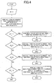
- Fig. 5 is a flowchart illustrating the present invention image de-ringing filter method. Although the method is depicted as a sequence of numbered steps for clarity, no order should be inferred from the numbering unless explicitly stated. It should be understood that some of these steps may be skipped, performed in parallel, or performed without the requirement of maintaining a strict order of sequence.
- the method starts at Step 500.
- Step 502 decodes compressed image information.
- Step 504 accepts a plurality of image pixels. That is, the decoded image information is accepted.
- Step 506 collects data from a first group of pixels neighboring a test pixel.
- Step 508 decides if the test pixel includes image ringing artifacts, in response to the first group data.
- Step 510 collects data from a second group of pixels neighboring the test pixel.
- Step 512 in response to the second group data, generates a filtered value (FV).
- Step 514 replaces the test pixel actual value with FV. Note, FV is not necessarily calculated, or used to replace the test pixel, depending upon the result of the decision process in Step 508.
- collecting data from a second group of pixels neighboring a test pixel in Step 510 includes performing a mathematical operation on the second group of pixels. For example, collecting data from a second group of pixels neighboring the test pixel in Step 510 includes collecting data from 8 pixels neighboring the test pixel. In another aspect, Step 510 adds the test pixel to the second group of pixels.
- collecting data from a first group of pixels neighboring a test pixel in Step 506 may include performing a mathematical operation on the first group of pixels.
- Step 506 compares the results of the mathematical operation to a threshold.
- performing a mathematical operation on the first group of pixels may include substeps.
- Step 506a defines a matrix.
- Step 506b multiplies the first group of pixels by the matrix.
- the matrix is defined such that a zero value is assigned to the position of the test pixel in the matrix.
- performing a mathematical operation on the first group of pixels may include comparing values of pixels on opposite sides of a coordinate axis bisecting the test pixel.
- comparing values of pixels on opposite sides of a coordinate axis bisecting the test pixel may include: subtracting the values of pixels on a first side of the coordinate axis from pixels on a second side of the coordinate axis, opposite of the first side; and, comparing the difference to a threshold.
- a fixed threshold value is selected.
- the values of pixels may be compared on opposite sides of a plurality of coordinate axes, oriented in a plurality of directions.
- data is collected from a group of 4 pixels neighboring the test pixel.
- Step 506 values of pixels on opposite sides of a coordinate axis bisecting the test pixel may be compared (Step 506) as follows:
- Step 508 deciding if the test pixel includes image ringing artifacts in Step 508 includes deciding that P(i,j) includes ringing artifacts, if S(i,j) ⁇ threshold.
- generating FV in Step 512 includes using pixels from the second group to calculate FV, if they are equal to a first map value.
- FV is generated using a first map value of 0.
- the first map value is not equal to 1.
- FV can be calculated by selecting pixels from the second group, if they are equal to the first map value.
- Step 504 accepts a plurality of image pixel sets, in a plurality of frames, then generating FV in Step 512 may include substeps.
- Step 512a randomly selects a first collection of pixel positions with respect to the test pixel.
- Step 512b uses pixels in the first collection to calculate FV for each test pixel in every image pixel set, in every frame.
- Step 512a randomly selects a first collection of pixel positions with respect to the test pixel in a first image pixel set in a current frame.
- Step 512b uses pixels in the first collection to calculate FV for each test pixel in every image pixel set in the current frame.
- Step 512c randomly reselects a second collection of pixel positions in an image pixel set in a frame subsequent to the current frame.
- Step 512d uses pixels in the second collection to calculate FV for each test pixel in every image pixel set in the subsequent frame.
- Step 512 selects a predetermined collection of pixel positions with respect to the test pixel. If Step 504 accepts a plurality of image pixel sets in a plurality of frames, then Step 512 generates FV by selecting the pixels in the predetermined pixel positions to calculate FV for each test pixel in every image pixel set, in every frame. Alternately, Step 512e selects the pixels in a predetermined first collection of pixel positions to calculate FV for each test pixel in every image pixel set in a current frame. Step 512f selects the pixels in a predetermined second collection of pixel positions to calculate FV for each test pixel in every image pixel set in a frame subsequent to the current frame.
- Step 512e may select the pixels in the predetermined first collection of pixel positions to calculate FV for test pixels in a first image pixel set. Then, Step 512f selects the pixels in the predetermined second collection of pixel positions to calculate FV for test pixels in a second image pixel set.
- using pixels from the second group to calculate FV, if they are equal to a first map value (Step 512), may include other substeps (not shown).
- Step 512g selectively weights second group pixel values.
- Step 512h sums the weighted values.
- Step 512i averages.
- the test pixel may be added to the second group of pixels.
- Step 512g may weigh the pixels in response to the number of pixels in the second group.
- the generation of FV may include:
- the generation of FV may include:
- Step 512j loads a lookup table (LUT) with the pre-calculated values. Typically, the LUT is loaded before the decision and filtering processes are performed.
- LUT lookup table
- Step 512j loads a value for each nE indicating the number of times the test pixel P(i,j) is added. In another aspect, Step 512j loads a value for each nE indicating the number of times the result is right shifted. In a third aspect, Step 512j loads a value for each nE indicating if a pixel value from second group of pixels is subtracted or not.
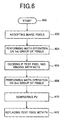
- Fig. 6 is a flowchart illustrating another aspect of the present invention image de-ringing filter method.
- the method starts at Step 600.
- Step 602 accepts a plurality of image pixels.
- Step 604 performs a mathematical operation on a first group of pixels neighboring a test pixel.
- Step 606 in response to the first group operation, decides if the test pixel includes image ringing artifacts.
- Step 608 performs a mathematical operation on a second group of pixels neighboring the test pixel.
- Step 610 in response to the second group operation, generates FV.
- Step 612 replaces the test pixel actual value with FV.
- performing a mathematical operation on the first group of pixels includes: defining a matrix; and, multiplying the first group of pixels by the matrix.
- Step 604 compares values of pixels on opposite sides of a coordinate axis bisecting the test pixel.
- generating a FV in response to the second group operation includes: generating a map value for each pixel in the second group; and, using pixels from the second group to calculate FV, if they are equal to a first map value.
- a system and method have been provided for removing ringing artifacts that can be simply implemented after a compressed video decoding process.
- Some examples of specific algorithms have been described to clarify the invention. However, the invention is not limited to merely these examples.
- abstract compressed video standards have been described, the present invention may be adapted for use with the following video standards: MPEG1, MPEG2, MPEG4, H.263, H.263+, H.263++, and H.264.
- Other variations and embodiments of the invention will occur to those skilled in the art.
Abstract
An image de-ringing filter system and method are
provided. The method comprises: accepting image pixels (504);
collecting data from a first group of pixels neighboring a test pixel
(506); in response to the first group data, deciding if the test pixel
includes image ringing artifacts (508); collecting data from a second
group of pixels neighboring the test pixel (510); in response to the
second group data, generating a filtered value (FV) (512b/512f); and,
replacing the test pixel actual value with FV (514). Typically,
collecting data from the first and second group of pixels includes the
performance of a mathematical operation. For example, a matrix may
be defined for the multiplication of the first group of pixels. Values of
pixels on a first side of the coordinate axis may be subtracted from
pixels on a second side of the coordinate axis, opposite of the first side.
Then, the difference is compared to a threshold.
Description
This invention generally relates to compressed image and
video coding and, more particularly, to a method for filtering ringing
artifacts that may occur as a result of compressed image and video
encoding/decoding processes.
Computation resources and bandwidth can be saved by
encoding images and videos at a low bit-rate. However, low bit-rate
encoding may result in several types of artifacts in the decompressed
images. The most notable artifacts include blocking and ringing
artifacts. The ringing artifacts are typically observed around the true
edges of an image. The ringing artifacts are also referred to as
mosquito artifacts, as they tend to be annoying, especially in moving
images (video sequences). A variety of filters exist for filtering out
these unwanted artifacts. These include de-blocking and de-ringing
filters. For de-ringing, conventional methods operate in both the
transform and pixel domains. Other conventional de-ringing filters
make use of quantization information. One drawback of all the above-mentioned
de-ringing filters is that are computationally intensive.
Thus, the filters are not suitable for all receiving systems. Further, the
filters may result in unacceptable delays, even when they can be
implemented.
It would be advantageous if a low complexity de-ringing
filter could be developed for ringing artifact reduction.
The present invention is a de-ringing filter with a low
computational complexity. A decision to apply the filter is made for
each pixel based on its edge strength. In one aspect, a 3x3 kernel is
used for filtering. Only the non-edge neighbor pixels are used to filter
the current (test) pixel. In this aspect, the filter uses all of the non-edge
neighbor pixels and the current pixel weighted appropriately,
based on the total number of non-edge neighbor pixels. The invention
works entirely in the pixel domain and does not use or need any
quantization information. Further, the solution is not necessarily block
or macroblock-based.
Accordingly, an image de-ringing filter method is provided.
The method comprises: accepting a plurality of image pixels; collecting
data from a first group of pixels neighboring a test pixel; in response to
the first group data, deciding if the test pixel includes image ringing
artifacts; collecting data from a second group of pixels neighboring the
test pixel; in response to the second group data, generating a filtered
value (FV); and, replacing the test pixel actual value with FV.
Typically, collecting data from the first and second group
of pixels includes the performance of a mathematical operation. For
example, a matrix may be defined for the multiplication of the first
group of pixels. The mathematical operation may involve the
comparison of pixels values on opposite sides of a coordinate axis
bisecting the test pixel. More specifically, values of pixels on a first
side of the coordinate axis may be subtracted from pixels on a second
side of the coordinate axis, opposite of the first side. Then, the
difference is compared to a threshold.
In another aspect, generating a FV in response to the
second group operation includes: generating a map value for each pixel
in the second group; and, using pixels from the second group to
calculate FV, if they are equal to a first map value. Specifics of map
values and the definition of the second group are provided.
Additional details of the above-described method, and an
image de-ringing filter system are provided below.
Fig. 1 is a schematic block diagram of the present
invention image de-ringing filter system. The system 100 comprises a
decision unit 102 having an input on line 104 to accept a plurality of
image pixels. The decision unit 102 collects data from a first group of
pixels neighboring a test pixel. In response to the first group data, the
decision unit 102 supplies a decision at an output on line 106 as to
whether the test pixel includes image ringing artifacts. A filter 108
has an input on line 104 to accept the plurality of image pixels and an
input on line 106 to accept the decision. The filter 108 collects data
from a second group of pixels neighboring the test pixel. In response to
the second group data, the filter generates a filtered value (FV) and
supplies the FV at an output on line 110 as a replacement to the test
pixel actual value.
A decoder 112 has a connection on line 114 to accepted
encoded video information. The encoded video may come from a
network, local storage, or other source. This information may be
encoded in a standard such as moving picture experts group (MPEG) or
H.264 standards, to name a few examples. The decoder 112 has an
output on line 104 to supply the plurality of image pixels to the
decision unit 102, and to the filter 108, as decoded image information.
Fig. 2 is a diagram depicting a test pixel, and a group of
neighboring pixels. Pixels from the first group are represented with a
"1", while pixels from the second group are represented with a "2".
Note, the first and second group of pixels are not necessarily the same.
Although 9 pixel positions are shown, neither the first nor the second
group of pixels is limited to any particular number.
Typically, the filter performs a mathematical operation on
the second group of pixels. Likewise, the decision unit typically
performs a mathematical operation on the first group of pixels. For
example, the decision unit may define a matrix and multiply the first
group of pixels by the matrix, or more than one matrix. In some
aspects, the decision unit defines a matrix such that a zero value is
assigned to the position of the test pixel in the matrix. In some aspects
matrix may be used for a vector dot product. In one aspect, the
decision unit may compare values of pixels on opposite sides of a
coordinate axis bisecting the test pixel. For example, 1a, 1d, and 1g
may be compared to 1c, 1f, and 1i. In another aspect, the decision unit
subtracts the values of pixels on a first side of the coordinate axis from
pixels on a second side of the coordinate axis, opposite of the first side,
and compares the difference to a threshold.
In a different aspect, the decision unit compares the
values of pixels on opposite sides of a plurality of coordinate axes,
oriented in a plurality of directions. For example, pixels 1a and 1c may
be compared to pixels 1g and 1i, while pixels 1a and 1g are compared to
pixels 1c and 1i. In one aspect, the decision unit collects data from a
group of 4 pixels neighboring the test pixel. For example, pixel
positions 1a, 1c, 1g, and 1i can be used. The results of any of the
mathematical operations can be compared to a threshold as a means of
making a decision as to whether a test pixel is to be filtered.
With respect to a test pixel P(i,j), with i and j indicating
row and column indices, respectively, and P(i,j) representing a pixel
gray value, operators H1 and H2 may be used to derive gradient values
g H1 (i,j) and g H2(i,j), respectively, where
H1 = [10 -1];
and,

The decision unit calculates S(i,j) = (|g H1 (i,j)| + |g H2 (i,j)| + 1)
>> 1, where >> x represents a binary value right-shift of x. Then, the
decision unit decides that P(i,j) is a ringing artifact, if S(i,j) < threshold.
Note, this examples uses 4 test pixel neighbors, from the immediately
neighboring 8 pixels to make a filter decision.
In other aspects, the position of pixels, the number of
pixels, and the size of the neighboring group from which the pixels are
selected may be different. For example, the operators may be as
follows:
H1 = [110 -1-1];
and,

X-axis, reflection, y-axis reflection, diagonal reflection,
diagonal reflection symmetry, -90 degree rotation symmetry, centro
symmetry, quadrantal symmetry, diagonal symmetry, 4-fold rotation
symmetry, and octagonal symmetry are examples of other coordinate
axes comparisons that can be made.
Referring now to the filter, in some aspects the filter may
add the test pixel to the second group of pixels. Alternately, the test
pixel value is not used to calculate FV. In one aspect, the filter collects
data from 8 pixels neighboring the test pixel (2a, 2b, 2c, 2d, 2f, 2g, 2h,
and 2i). However, other definitions of the second pixel group are
possible.
The decision unit, in response to comparing S(i,j) to the
threshold, generates a map value M(i,j) for P(i,j), where:
M(i,j) = 1, if S(i,j) ≥ threshold;
and,
M(i,j) = 0, if S(i,j) < threshold;
Then, the filter uses pixels from the second group to
calculate FV, if they are equal to a first map value. In some aspects,
the filter uses a first map value equal to 0. Alternately, the filter uses
a first map value not equal to 1.
In one aspect of the system, the filter selects pixels from
the second group to calculate FV, if they are equal to the first map
value. For example, the filter may randomly select pixels from the
second group to calculate FV, if they are equal to the first map value.
More generally, the filter may accept a plurality of image pixel sets, in
a plurality of frames. Then, it generates FV by randomly selecting a
first collection of pixel positions with respect to the test pixel, and uses
pixels in the first collection to calculate FV for each test pixel in every
image pixel set, in every frame.
In another aspect, the filter generates FV by randomly
selecting a first collection of pixel positions with respect to the test
pixel in a first image pixel set in a current frame, and uses pixels in the
first collection to calculate FV for each test pixel in every image pixel
set in the current frame. Further, the filter randomly reselects a
second collection of pixel positions in an image pixel set in a frame
subsequent to the current frame, and uses pixels in the second
collection to calculate FV for each test pixel in every image pixel set in
the subsequent frame.
In another aspect, the filter selects pixels in
predetermined pixel positions, with respect to the test pixel, from the
second group to calculate FV, if it is equal to the first map value. More
generally, the filter may accept a plurality of image pixel sets in a
plurality of frames, and select the pixels in the predetermined pixel
positions to calculate FV for each test pixel in every image pixel set, in
every frame. For example, the filter may select the pixels in a
predetermined first collection of pixel positions to calculate FV for each
test pixel in every image pixel set in a current frame, and select the
pixels in a predetermined second collection of pixel positions to
calculate FV for each test pixel in every image pixel set in a frame
subsequent to the current frame.
In another aspect, the filter generates FV by selecting the
pixels in the predetermined first collection of pixel positions to
calculate FV for test pixels in a first image pixel set and, then,
selecting the pixels in the predetermined second collection of pixel
positions to calculate FV for test pixels in a second image pixel set.
In a different aspect of the invention, the filter uses pixels
from the second group to calculate FV, if they are equal to a first map
value, by selectively weighting second group pixel values. Then, the
weighted values are summed and averaged. In this aspect, the filter
may add the test pixel to the second group of pixels. The filter may
also selectively weigh in response to number of pixels in the second
group.
The following is a specific example of a filter algorithm.
The filter generates FV by:
In an alternate algorithm, the filter generates FV by:
Returning to Fig. 1, some aspects of the system 100
include an accessible memory 120 including a lookup table (LUT) 122
with pre-calculated values. The filter 108 generates a FV in response
accessing the LUT 122.
Fig. 3 is a drawing depicting the LUT of Fig. 1. As shown,
the LUT 122 is indexed by nE values. The filter calculates nE, where
nE = the total number of pixels in the second group with the first map
value. The filter then uses the calculated nE value to access the LUT
122. In one aspect, the LUT 122 includes a value for each nE
indicating the number of times the test pixel P(i,j) is added. In another
aspect, the LUT 122 includes a value for each nE indicating the
number of times the result is right shifted. In a different aspect, the
LUT 122 includes a value for each nE indicating if a pixel value from
second group of pixels is subtracted, or not.
As described above, the present invention de-ringing filter
consists of decision and filtering functions. The following description is
one specific example of the de-ringing filter.
For each pixel, a decision is made as to whether the pixel
should be filtered or left unprocessed. The decision is based on
following computation:
For each pixel, use the operators H 1 = [1 0 -1] and
 to compute two gradient values that are denoted by
gH 1 (i, j) and gH 2 (i, j). The operators are selected so that the actual
current (test) pixel itself is not used in the calculation of its
Strength(i, j) . Instead, only its 4 neighbors are used for this
computation. Then a local measure Strength(i, j) for the current pixel
(i, j) is calculated as:
to compute two gradient values that are denoted by
gH 1 (i, j) and gH 2 (i, j). The operators are selected so that the actual
current (test) pixel itself is not used in the calculation of its
Strength(i, j) . Instead, only its 4 neighbors are used for this
computation. Then a local measure Strength(i, j) for the current pixel
(i, j) is calculated as:
Strength (i,j ) = (| gH 1 (i, j ) | + | gH 2 (i, j ) 1+1) >> 1;
 ,where (i, j) is the pixel index and Threshold is a parameter
which controls the filtering decision. The Threshold is a parameter that
can be manipulated to vary the effective strength of the filter. A high-threshold
value results in more pixels getting filtered and, thus, a
stronger filter. A low-threshold value results in a lesser number of
pixels getting filtered and, thus, a weaker filter.
,where (i, j) is the pixel index and Threshold is a parameter
which controls the filtering decision. The Threshold is a parameter that
can be manipulated to vary the effective strength of the filter. A high-threshold
value results in more pixels getting filtered and, thus, a
stronger filter. A low-threshold value results in a lesser number of
pixels getting filtered and, thus, a weaker filter.
If the Strength(i, j) of a test pixel is less than the threshold,
then the de-ringing filter is applied to this pixel. Otherwise, the pixel
is left unprocessed, i.e., its value is used without changing. If the
decision is made to apply a de-ringing filter to a pixel, then the
Strength(i, j) value is computed and compared to the Threshold , to obtain
the Map (i, j) values for the current pixel's 8 neighbors in the 3x3 size
kernel. These values are used in the de-ringing filter stage, as
explained below.
Based on the decision from the previous stage, the pixels
are processed by de-ringing filter, or not processed. The filter has a low
complexity, as compared to other approaches, and is signal adaptive.
The filtering can be done in place, or the results could be stored in a
separate memory store. For example, satisfactory results are obtained
with an in-place computation approach, using a 3x3 kernel.
Fig. 4 is a drawing illustrating an exemplary aspect of the
present invention filter. The filter can be realized using only addition,
subtraction, and shift operations. The multiplication operations in Fig.
4 can also be realized as multiple addition operations. In one case, a
randomly (or selectively - based on some criterion) chosen neighbor
pixel is not used in the filtering of the current pixel (if nE is equal to 8,
for example). A lookup table can be used to realize the filter. The
lookup table can be indexed by the value nE, and can store the
information about the number of times the center pixel is added. The
LUT can also be used if any neighbor pixels need to be subtracted (or
effectively not used). The resulting average value is used to replace the
current pixel under consideration.
Fig. 5 is a flowchart illustrating the present invention
image de-ringing filter method. Although the method is depicted as a
sequence of numbered steps for clarity, no order should be inferred
from the numbering unless explicitly stated. It should be understood
that some of these steps may be skipped, performed in parallel, or
performed without the requirement of maintaining a strict order of
sequence. The method starts at Step 500.
Step 502 decodes compressed image information. Step
504 accepts a plurality of image pixels. That is, the decoded image
information is accepted. Step 506 collects data from a first group of
pixels neighboring a test pixel. Step 508 decides if the test pixel
includes image ringing artifacts, in response to the first group data.
Step 510 collects data from a second group of pixels neighboring the
test pixel. Step 512, in response to the second group data, generates a
filtered value (FV). Step 514 replaces the test pixel actual value with
FV. Note, FV is not necessarily calculated, or used to replace the test
pixel, depending upon the result of the decision process in Step 508.
In one aspect, collecting data from a second group of pixels
neighboring a test pixel in Step 510 includes performing a
mathematical operation on the second group of pixels. For example,
collecting data from a second group of pixels neighboring the test pixel
in Step 510 includes collecting data from 8 pixels neighboring the test
pixel. In another aspect, Step 510 adds the test pixel to the second
group of pixels.
Likewise, collecting data from a first group of pixels
neighboring a test pixel in Step 506 may include performing a
mathematical operation on the first group of pixels. In some aspects,
Step 506 compares the results of the mathematical operation to a
threshold.
For example, performing a mathematical operation on the
first group of pixels may include substeps. Step 506a defines a matrix.
Step 506b multiplies the first group of pixels by the matrix. In one
aspect, the matrix is defined such that a zero value is assigned to the
position of the test pixel in the matrix.
In one aspect, performing a mathematical operation on
the first group of pixels (Step 506) may include comparing values of
pixels on opposite sides of a coordinate axis bisecting the test pixel.
For example, comparing values of pixels on opposite sides of a
coordinate axis bisecting the test pixel may include: subtracting the
values of pixels on a first side of the coordinate axis from pixels on a
second side of the coordinate axis, opposite of the first side; and,
comparing the difference to a threshold. In some aspects, a fixed
threshold value is selected. Further, the values of pixels may be
compared on opposite sides of a plurality of coordinate axes, oriented in
a plurality of directions. In another example, data is collected from a
group of 4 pixels neighboring the test pixel.
More specifically, values of pixels on opposite sides of a
coordinate axis bisecting the test pixel may be compared (Step 506) as
follows:

Then, deciding if the test pixel includes image ringing
artifacts in Step 508 includes deciding that P(i,j) includes ringing
artifacts, if S(i,j) < threshold.
Additionally, Step 506 may, in response to comparing
S(i,j) to the threshold, generate a map value M(i,j) for P(i,j), where:
M(i,j) = 1, if S(i,j) ≥ threshold;
and,
M(i,j) = 0, if S(ij) < threshold.
Then, generating FV in Step 512 includes using pixels
from the second group to calculate FV, if they are equal to a first map
value. In some aspects, FV is generated using a first map value of 0.
In other aspects, the first map value is not equal to 1. Alternately, FV
can be calculated by selecting pixels from the second group, if they are
equal to the first map value.
For example, pixels may be randomly selected from the
second group for the calculation of FV, if they are equal to the first map
value. If Step 504 accepts a plurality of image pixel sets, in a plurality
of frames, then generating FV in Step 512 may include substeps. Step
512a randomly selects a first collection of pixel positions with respect to
the test pixel. Step 512b uses pixels in the first collection to calculate
FV for each test pixel in every image pixel set, in every frame. In a
different aspect, Step 512a randomly selects a first collection of pixel
positions with respect to the test pixel in a first image pixel set in a
current frame. Step 512b uses pixels in the first collection to calculate
FV for each test pixel in every image pixel set in the current frame.
Step 512c (not shown) randomly reselects a second collection of pixel
positions in an image pixel set in a frame subsequent to the current
frame. Step 512d (not shown) uses pixels in the second collection to
calculate FV for each test pixel in every image pixel set in the
subsequent frame.
In another aspect, Step 512 selects a predetermined
collection of pixel positions with respect to the test pixel. If Step 504
accepts a plurality of image pixel sets in a plurality of frames, then
Step 512 generates FV by selecting the pixels in the predetermined
pixel positions to calculate FV for each test pixel in every image pixel
set, in every frame. Alternately, Step 512e selects the pixels in a
predetermined first collection of pixel positions to calculate FV for each
test pixel in every image pixel set in a current frame. Step 512f selects
the pixels in a predetermined second collection of pixel positions to
calculate FV for each test pixel in every image pixel set in a frame
subsequent to the current frame. As another alternative, Step 512e
may select the pixels in the predetermined first collection of pixel
positions to calculate FV for test pixels in a first image pixel set. Then,
Step 512f selects the pixels in the predetermined second collection of
pixel positions to calculate FV for test pixels in a second image pixel set.
In another aspect, using pixels from the second group to
calculate FV, if they are equal to a first map value (Step 512), may
include other substeps (not shown). Step 512g selectively weights
second group pixel values. Step 512h sums the weighted values. Step
512i averages. With this aspect, the test pixel may be added to the
second group of pixels. Further, Step 512g may weigh the pixels in
response to the number of pixels in the second group.
In another aspect, the generation of FV (Step 512) may
include:
Alternately, the generation of FV may include:
In other aspects, generating FV in response to the second
group data includes other substeps (not shown). Step 512j loads a
lookup table (LUT) with the pre-calculated values. Typically, the LUT
is loaded before the decision and filtering processes are performed.
Step 512k accesses the LUT. For example, Step 512k1 calculates nE =
the total number of pixels in the second group with the first map value.
Then, Step 512k2 uses nE to access the LUT.
In one aspect, Step 512j loads a value for each nE
indicating the number of times the test pixel P(i,j) is added. In another
aspect, Step 512j loads a value for each nE indicating the number of
times the result is right shifted. In a third aspect, Step 512j loads a
value for each nE indicating if a pixel value from second group of pixels
is subtracted or not.
Fig. 6 is a flowchart illustrating another aspect of the
present invention image de-ringing filter method. The method starts
at Step 600. Step 602 accepts a plurality of image pixels. Step 604
performs a mathematical operation on a first group of pixels
neighboring a test pixel. Step 606, in response to the first group
operation, decides if the test pixel includes image ringing artifacts.
Step 608 performs a mathematical operation on a second group of
pixels neighboring the test pixel. Step 610, in response to the second
group operation, generates FV. Step 612 replaces the test pixel actual
value with FV.
In one aspect, performing a mathematical operation on
the first group of pixels (Step 604) includes: defining a matrix; and,
multiplying the first group of pixels by the matrix. In another aspect,
Step 604 compares values of pixels on opposite sides of a coordinate
axis bisecting the test pixel.
In one aspect, generating a FV in response to the second
group operation (Step 610) includes: generating a map value for each
pixel in the second group; and, using pixels from the second group to
calculate FV, if they are equal to a first map value.
A system and method have been provided for removing
ringing artifacts that can be simply implemented after a compressed
video decoding process. Some examples of specific algorithms have
been described to clarify the invention. However, the invention is not
limited to merely these examples. Although abstract compressed video
standards have been described, the present invention may be adapted
for use with the following video standards: MPEG1, MPEG2, MPEG4,
H.263, H.263+, H.263++, and H.264. Other variations and
embodiments of the invention will occur to those skilled in the art.
Claims (75)
- An image de-ringing filter method, the method comprising:accepting a plurality of image pixels;collecting data from a first group of pixels neighboring a test pixel;in response to the first group data, deciding if the test pixel includes image ringing artifacts;collecting data from a second group of pixels neighboring the test pixel;in response to the second group data, generating a filtered value (FV); and,replacing the test pixel actual value with FV.
- The method of claim 1 wherein collecting data from a second group of pixels neighboring a test pixel includes performing a mathematical operation on the second group of pixels.
- The method of claim 1 wherein collecting data from a first group of pixels neighboring a test pixel includes performing a mathematical operation on the first group of pixels.
- The method of claim 3 wherein collecting data from a first group of pixels neighboring a test pixel further includes comparing the results of the mathematical operation to a threshold.
- The method of claim 3 wherein performing a mathematical operation on the first group of pixels includes:defining a matrix; and,multiplying the first group of pixels by the matrix.
- The method of claim 5 wherein the matrix is defined such that a zero value is assigned to the position of the test pixel in the matrix.
- The method of claim 3 wherein performing a mathematical operation on the first group of pixels includes comparing values of pixels on opposite sides of a coordinate axis bisecting the test pixel.
- The method of claim 7 wherein comparing values of pixels on opposite sides of a coordinate axis bisecting the test pixel includes:subtracting the values of pixels on a first side of the coordinate axis from pixels on a second side of the coordinate axis, opposite of the first side; and,comparing the difference to a threshold.
- The method of claim 8 wherein comparing values of pixels on opposite sides of a coordinate axis bisecting the test pixel includes comparing the values of pixels on opposite sides of a plurality of coordinate axes, oriented in a plurality of directions.
- The method of claim 7 wherein collecting data from a first group of pixels neighboring a test pixel includes collecting data from a group of 4 pixels neighboring the test pixel.
- The method of claim 9 wherein comparing values of pixels on opposite sides of a coordinate axis bisecting the test pixel includes:wherein deciding if the test pixel includes image ringing artifacts includes deciding that P(ij) includes ringing artifacts, if S(i,j) < threshold.with respect to a test pixel P(i,j), with i and j indicating row and column indices, respectively, and P(i,j) representing a pixel gray value, using operators H1 and H2 to derive gradient values g H1 (i,j) and g H2 (i,j), respectively, wherecalculating

- The method of claim 7 further comprising:selecting a fixed threshold value.
- The method of claim 1 further comprising:wherein accepting a plurality of image pixels includes accepting the decoded image information.decoding compressed image information; and,
- The method of claim 1 wherein collecting data from a second group of pixels neighboring the test pixel includes adding the test pixel to the second group of pixels.
- The method of claim 1 wherein collecting data from a second group of pixels neighboring the test pixel includes collecting data from 8 pixels neighboring the test pixel.
- The method of claim 11 wherein comparing values of pixels on opposite sides of a coordinate axis bisecting the test pixel additional includes:wherein generating FV includes using pixels from the second group to calculate FV, if they are equal to a first map value.in response to comparing S(i,j) to the threshold, generating a map value M(i,j) for P(i,j), where:
- The method of claim 16 wherein generating FV includes the first map value being equal to 0.
- The method of claim 16 wherein generating FV includes the first map value not being equal to 1.
- The method of claim 16 wherein generating FV includes selecting pixels from the second group to calculate FV, if they are equal to the first map value.
- The method of claim 19 wherein generating FV includes randomly selecting pixels from the second group to calculate FV, if they are equal to the first map value.
- The method of claim 20 wherein accepting a plurality of image pixels includes accepting a plurality of image pixel sets, in a plurality of frames;
wherein generating FV includes:randomly selecting pixels in a first collection of pixel positions with respect to the test pixel;using pixels in the first collection to calculate FV for each test pixel in every image pixel set, in every frame. - The method of claim 20 wherein accepting a plurality of image pixels includes accepting a plurality of image pixel sets, in a plurality of frames;
wherein generating FV includes:randomly selecting a first collection of pixel positions with respect to the test pixel in a first image pixel set in a current frame;using pixels in the first collection to calculate FV for each test pixel in every image pixel set in the current frame;randomly reselecting a second collection of pixel positions in an image pixel set in a frame subsequent to the current frame; and,using pixels in the second collection to calculate FV for each test pixel in every image pixel set in the subsequent frame. - The method of claim 19 wherein selecting pixels from the second group to calculate FV, if they are equal to the first map value, includes selecting a predetermined collection of pixel positions with respect to the test pixel.
- The method of claim 23 wherein accepting a plurality of image pixels includes accepting a plurality of image pixel sets in a plurality of frames;
wherein generating FV includes selecting the pixels in a predetermined first collection of pixel positions to calculate FV for each test pixel in every image pixel set, in every frame. - The method of claim 23 wherein accepting a plurality of image pixels includes accepting a plurality of image pixel sets in a plurality of frames;
wherein generating FV includes:selecting the pixels in a predetermined first collection of pixel positions to calculate FV for each test pixel in every image pixel set in a current frame; and,selecting the pixels in a predetermined second collection of pixel positions to calculate FV for each test pixel in every image pixel set in a frame subsequent to the current frame. - The method of claim 23 wherein generating FV includes:selecting the pixels in a predetermined first collection of pixel positions to calculate FV for each test pixel in a first image pixel set; and,selecting the pixels in a predetermined second collection of pixel positions to calculate FV for each test pixel in a second image pixel set.
- The method of claim 16 wherein using pixels from the second group to calculate FV, if they are equal to a first map value, includes:selectively weighting second group pixel values;summing the weighted values; and,averaging.
- The method of claim 27 wherein collecting data from a second group of pixels neighboring the test pixel includes adding the test pixel to the second group of pixels.
- The method of claim 27 wherein selectively weighting second group pixel values includes weighting in response to number of pixels in the second group.
- The method of claim 16 wherein generating FV includes:calculating nV = sum of second group pixel values for pixels having a map value of 0;calculating nE = total number of pixels in the second group with a map value of 0;if nE = 1, then FV = (nV + P(i,j) +1) >> 1;if nE < 4, thenif nE < 8, thenif nE = 8, then
- The method of claim 16 wherein generating FV includes:calculating nV = sum of second group pixel values for pixels having a map value of 0;calculating nE = total number pixels in the second group with a map value of 0;if nE = 1, thenif nE < 4, thenif nE < 8, thenif nE = 8, then
- The method of claim 16 wherein generating a FV in response to the second group data includes:loading a lookup table (LUT) with the pre-calculated values; and,accessing the LUT.
- The method of claim 32 generating a FV includes:calculating nE = the total number of pixels in the second group with the first map value; and,using nE to access the LUT.
- The method of claim 32 loading a LUT with the pre-calculated values includes loading a value for each nE indicating the number of times the test pixel P(i,j) is added.
- The method of claim 32 loading a LUT with the pre-calculated values includes loading a value for each nE indicating the number of times the result is right shifted.
- The method of claim 32 loading a LUT with the pre-calculated values includes loading a value for each nE indicating if a pixel value from second group of pixels is subtracted.
- An image de-ringing filter method, the method comprising:accepting a plurality of image pixels;performing a mathematical operation on a first group of pixels neighboring a test pixel;in response to the first group operation, deciding if the test pixel includes image ringing artifacts;performing a mathematical operation on a second group of pixels neighboring the test pixel;in response to the second group operation, generating a filtered value (FV); and,replacing the test pixel actual value with FV.
- The method of claim 37 wherein performing a mathematical operation on the first group of pixels includes:defining a matrix; and,multiplying the first group of pixels by the matrix.
- The method of claim 37 wherein performing a mathematical operation on the first group of pixels includes comparing values of pixels on opposite sides of a coordinate axis bisecting the test pixel.
- The method of claim 37 generating a FV in response to the second group operation includes:generating a map value for each pixel in the second group; and,using pixels from the second group to calculate FV, if they are equal to a first map value.
- An image de-ringing filter system, the system comprising:a decision unit (102) having an input to accept a plurality of image pixels, the decision unit (102) collecting data from a first group of pixels neighboring a test pixel and, in response to the first group data, supplying a decision at an output as to whether the test pixel includes image ringing artifacts; and,a filter (108) having an input to accept the plurality of image pixels and an input to accept the decision, the filter collecting data from a second group of pixels neighboring the test pixel and, in response to the second group data, generating a filtered value (FV) and supplying the FV at an output as a replacement to the test pixel actual value.
- The system of claim 41 wherein the filter (108) performs a mathematical operation on the second group of pixels.
- The system of claim 41 wherein the decision unit (102) performs a mathematical operation on the first group of pixels.
- The system of claim 43 wherein the decision unit (102) compares the results of the mathematical operation to a threshold.
- The system of claim 43 wherein the decision unit (102) defines a matrix and multiplies the first group of pixels by the matrix.
- The system of claim 45 wherein the decision unit (102) defines a matrix such that a zero value is assigned to the position of the test pixel in the matrix.
- The system of claim 43 wherein the decision unit (102) compares values of pixels on opposite sides of a coordinate axis bisecting the test pixel.
- The system of claim 47 wherein the decision unit (102) subtracts the values of pixels on a first side of the coordinate axis from pixels on a second side of the coordinate axis, opposite of the first side, and compares the difference to a threshold.
- The system of claim 48 wherein the decision unit (102) compares the values of pixels on opposite sides of a plurality of coordinate axes, oriented in a plurality of directions.
- The system of claim 47 wherein the decision unit (102) collects data from a group of 4 pixels neighboring the test pixel.
- The system of claim 49 wherein the decision unit (102) :with respect to a test pixel P(i,j), with i and j indicating row and column indices, respectively, and P(i,j) represents a pixel gray value, uses operators H1 and H2 to derive gradient values g H1 (i,j) and g H2 (i,j), respectively, wherecalculates
 decides that P(i,j) is a ringing artifact, if S(i,j) < threshold.
 - The system of claim 41 further comprising:a decoder (112) having a connection to accepted encoded video information and an output to supply the plurality of image pixels to the decision unit (102), and to the filter (108), as decoded image information.
- The system of claim 41 wherein the filter (108) adds the test pixel to the second group of pixels.
- The system of claim 41 wherein the filter (108) collects data from 8 pixels neighboring the test pixel.
- The system of claim 51 wherein the decision unit (102) :wherein the filter (108) generates a map value for each pixel in the second group and uses pixels from the second group to calculate FV, if they are equal to a first map value.in response to comparing S(i,j) to the threshold, generates a map value M(i,j) for P(i,j), where:
- The system of claim 55 wherein the filter (108) uses a first map value equal to 0.
- The system of claim 55 wherein the filter (108) uses a first map value not equal to 1.
- The system of claim 55 wherein the filter (108) selects pixels from the second group to calculate FV, if they are equal to the first map value.
- The system of claim 58 wherein the filter (108) randomly selects pixels from the second group to calculate FV, if they are equal to the first map value.
- The system of claim 59 wherein the filter (108) accepts a plurality of image pixel sets, in a plurality of frames and generates FV by:randomly selecting a first collection of pixel positions with respect to the test pixel;using pixels in the first collection to calculate FV for each test pixel in every image pixel set, in every frame.
- The system of claim 59 wherein the filter (108) accepts a plurality of image pixel sets, in a plurality of frames and generates FV by:randomly selecting a first collection of pixel positions with respect to the test pixel in a first image pixel set in a current frame;using pixels in the first collection to calculate FV for each test pixel in every image pixel set in the current frame;randomly reselecting a second collection of pixel positions in an image pixel set in a frame subsequent to the current frame; and,using pixels in the second collection to calculate FV for each test pixel in every image pixel set in the subsequent frame.
- The system of claim 58 wherein the filter (108) selects predetermined pixel positions, with respect to the test pixel, from the second group to calculate FV, if they are equal to the first map value.
- The system of claim 62 wherein the filter (108) accepts a plurality of image pixel sets in a plurality of frames and selects the pixels in the predetermined pixel positions to calculate FV for each test pixel in every image pixel set, in every frame.
- The system of claim 62 wherein the filter (108) accepts a plurality of image pixel sets in a plurality of frames and generates FV by:selecting the pixels in a predetermined first collection of pixel positions to calculate FV for each test pixel in every image pixel set in a current frame; and,selecting the pixels in a predetermined second collection of pixel positions to calculate FV for each test pixel in every image pixel set in a frame subsequent to the current frame.
- The system of claim 62 wherein the filter (108) generates FV by:selecting the pixels in a predetermined first collection of pixel positions to calculate FV for test pixels in a first image pixel set; and,selecting the pixels in a predetermined second collection of pixel positions to calculate FV for test pixels a second image pixel set.
- The system of claim 55 wherein the filter (108) uses pixels from the second group to calculate FV, if they are equal to a first map value, by:selectively weighting second group pixel values;summing the weighted values; and,averaging.
- The system of claim 66 wherein the filter (108) adds the test pixel to the second group of pixels.
- The system of claim 66 wherein the filter (108) selectively weights in response to number of pixels in the second group.
- The system of claim 55 wherein the filter (108) generates FV by:calculating nV = sum of second group pixel values for pixels having a map value of 0;calculating nE = total number of pixels in the second group with a map value of 0;if nE = 1, thenif nE < 4, thenif nE < 8, thenifnE = 8,then
- The system of claim 55 wherein the filter (108) generates FV by:calculating nV = sum of second group pixel values for pixels having a map value of 0;calculating nE = total number pixels in the second group with a map value of 0;if nE = 1, thenif nE < 4, thenif nE < 8, thenif nE = 8, then
- The system of claim 55 further comprising:wherein the filter (108) generates a FV in response accessing the LUT (122).an accessible memory (120) including a lookup table (LUT) (122) with pre-calculated values;
- The system of claim 71 wherein the LUT (122) is indexed by nE values: and,
wherein the filter (108) calculates nE = the total number of pixels in the second group with the first map value, and uses nE to access the LUT (122). - The system of claim 72 wherein the LUT (122) includes a value for each nE indicating the number of times the test pixel P(i,j) is added.
- The system of claim 72 wherein the LUT (122) includes a value for each nE indicating the number of times the result is right shifted.
- The system of claim 72 wherein the LUT (122) includes a value for each nE indicating if a pixel value from second group of pixels is subtracted.
Applications Claiming Priority (6)
| Application Number | Priority Date | Filing Date | Title |
|---|---|---|---|
| US53504504P | 2004-01-06 | 2004-01-06 | |
| US53505004P | 2004-01-06 | 2004-01-06 | |
| US535050P | 2004-01-06 | ||
| US535045P | 2004-01-06 | ||
| US815029 | 2004-03-31 | ||
| US10/815,029 US7471845B2 (en) | 2004-01-06 | 2004-03-31 | De-ringing filter |
Publications (1)
| Publication Number | Publication Date |
|---|---|
| EP1553778A1 true EP1553778A1 (en) | 2005-07-13 |
Family
ID=34595970
Family Applications (1)
| Application Number | Title | Priority Date | Filing Date |
|---|---|---|---|
| EP04030974A Ceased EP1553778A1 (en) | 2004-01-06 | 2004-12-29 | De-ringing filter |
Country Status (3)
| Country | Link |
|---|---|
| US (2) | US7471845B2 (en) |
| EP (1) | EP1553778A1 (en) |
| JP (1) | JP2005198274A (en) |
Cited By (4)
| Publication number | Priority date | Publication date | Assignee | Title |
|---|---|---|---|---|
| EP1909227A1 (en) * | 2006-10-03 | 2008-04-09 | Vestel Elektronik Sanayi ve Ticaret A.S. | method of and apparatus for minimizing ringing artifacts in an input image |
| US8571347B2 (en) | 2008-09-09 | 2013-10-29 | Marvell World Trade Ltd. | Reducing digital image noise |
| WO2015020919A3 (en) * | 2013-08-06 | 2015-04-09 | Microsoft Corporation | Encoding video captured in low light |
| US9077990B2 (en) | 2010-07-28 | 2015-07-07 | Marvell World Trade Ltd. | Block noise detection in digital video |
Families Citing this family (24)
| Publication number | Priority date | Publication date | Assignee | Title |
|---|---|---|---|---|
| US8340177B2 (en) * | 2004-07-12 | 2012-12-25 | Microsoft Corporation | Embedded base layer codec for 3D sub-band coding |
| US8442108B2 (en) * | 2004-07-12 | 2013-05-14 | Microsoft Corporation | Adaptive updates in motion-compensated temporal filtering |
| US8374238B2 (en) | 2004-07-13 | 2013-02-12 | Microsoft Corporation | Spatial scalability in 3D sub-band decoding of SDMCTF-encoded video |
| JP4455487B2 (en) * | 2005-12-16 | 2010-04-21 | 株式会社東芝 | Decoding device, decoding method, and program |
| US8711925B2 (en) | 2006-05-05 | 2014-04-29 | Microsoft Corporation | Flexible quantization |
| JP5150224B2 (en) * | 2006-11-29 | 2013-02-20 | パナソニック株式会社 | Image processing method and image processing apparatus |
| US8238424B2 (en) | 2007-02-09 | 2012-08-07 | Microsoft Corporation | Complexity-based adaptive preprocessing for multiple-pass video compression |
| US8750390B2 (en) * | 2008-01-10 | 2014-06-10 | Microsoft Corporation | Filtering and dithering as pre-processing before encoding |
| US8160132B2 (en) | 2008-02-15 | 2012-04-17 | Microsoft Corporation | Reducing key picture popping effects in video |
| US8953673B2 (en) * | 2008-02-29 | 2015-02-10 | Microsoft Corporation | Scalable video coding and decoding with sample bit depth and chroma high-pass residual layers |
| US8711948B2 (en) * | 2008-03-21 | 2014-04-29 | Microsoft Corporation | Motion-compensated prediction of inter-layer residuals |
| US8897359B2 (en) | 2008-06-03 | 2014-11-25 | Microsoft Corporation | Adaptive quantization for enhancement layer video coding |
| US9571856B2 (en) * | 2008-08-25 | 2017-02-14 | Microsoft Technology Licensing, Llc | Conversion operations in scalable video encoding and decoding |
| US8213503B2 (en) * | 2008-09-05 | 2012-07-03 | Microsoft Corporation | Skip modes for inter-layer residual video coding and decoding |
| TWI415470B (en) * | 2008-10-09 | 2013-11-11 | Mstar Semiconductor Inc | Deringing device and method |
| US8306355B2 (en) * | 2009-07-13 | 2012-11-06 | Sharp Laboratories Of America, Inc. | Methods and systems for reducing compression artifacts |
| US9251569B2 (en) * | 2013-09-10 | 2016-02-02 | Adobe Systems Incorporated | Removing noise from an image via efficient patch distance computations |
| US9380226B2 (en) * | 2014-06-04 | 2016-06-28 | Toshiba America Electronic Components, Inc. | System and method for extraction of a dynamic range zone image |
| RU2696316C1 (en) | 2015-09-25 | 2019-08-01 | Хуавэй Текнолоджиз Ко., Лтд. | Adaptive sharpening filter for encoding with prediction |
| RU2696311C1 (en) | 2015-09-25 | 2019-08-01 | Хуавэй Текнолоджиз Ко., Лтд. | Video motion compensation device and method with selectable interpolation filter |
| KR102143736B1 (en) | 2015-09-25 | 2020-08-12 | 후아웨이 테크놀러지 컴퍼니 리미티드 | Video motion compensation apparatus and method |
| CA2999824C (en) | 2015-09-25 | 2021-08-03 | Huawei Technologies Co., Ltd. | Apparatus and method for video motion compensation |
| JP6556942B2 (en) | 2015-09-25 | 2019-08-07 | ホアウェイ・テクノロジーズ・カンパニー・リミテッド | Apparatus and method for video motion compensation |
| US10091533B2 (en) | 2016-02-18 | 2018-10-02 | Cisco Technology, Inc. | Generalized filter for removing video compression artifacts |
Citations (6)
| Publication number | Priority date | Publication date | Assignee | Title |
|---|---|---|---|---|
| EP0797349A2 (en) * | 1996-03-23 | 1997-09-24 | Samsung Electronics Co., Ltd. | Signal adaptive postprocessing system for reducing blocking effects and ringing noise |
| WO2000014968A1 (en) * | 1998-09-10 | 2000-03-16 | Wisconsin Alumni Research Foundation | Method and apparatus for the reduction of artifact in decompressed images using morphological post-filtering |
| US20020122602A1 (en) * | 2000-12-26 | 2002-09-05 | Rouvellou Laurent Jean Marie | Data processing method |
| US20030081854A1 (en) * | 2001-06-12 | 2003-05-01 | Deshpande Sachin G. | Filter for combined de-ringing and edge sharpening |
| WO2003081534A1 (en) * | 2002-03-26 | 2003-10-02 | Koninklijke Philips Electronics N.V. | Video signal post-processing method |
| EP1351508A2 (en) * | 2002-04-05 | 2003-10-08 | Seiko Epson Corporation | Adaptive post-filtering for reducing noise in highly compressed image/video coding |
Family Cites Families (20)
| Publication number | Priority date | Publication date | Assignee | Title |
|---|---|---|---|---|
| JP2536684B2 (en) | 1990-09-29 | 1996-09-18 | 日本ビクター株式会社 | Image coding device |
| US5598184A (en) * | 1992-03-27 | 1997-01-28 | Hewlett-Packard Company | Method and apparatus for improved color recovery in a computer graphics system |
| US5802218A (en) * | 1994-11-04 | 1998-09-01 | Motorola, Inc. | Method, post-processing filter, and video compression system for suppressing mosquito and blocking atrifacts |
| US5581371A (en) * | 1995-03-07 | 1996-12-03 | Eastman Kodak Company | Error diffusion method |
| US5852475A (en) * | 1995-06-06 | 1998-12-22 | Compression Labs, Inc. | Transform artifact reduction process |
| US5819035A (en) * | 1995-10-20 | 1998-10-06 | Matsushita Electric Industrial Co., Ltd. | Post-filter for removing ringing artifacts of DCT coding |
| US5850294A (en) * | 1995-12-18 | 1998-12-15 | Lucent Technologies Inc. | Method and apparatus for post-processing images |
| DE19626985C1 (en) * | 1996-07-04 | 1998-01-02 | Siemens Ag | Method and arrangement for reducing coding artifacts of block-based image coding methods and object-based image coding methods |
| US6188799B1 (en) * | 1997-02-07 | 2001-02-13 | Matsushita Electric Industrial Co., Ltd. | Method and apparatus for removing noise in still and moving pictures |
| KR100234316B1 (en) * | 1997-04-04 | 1999-12-15 | 윤종용 | Signal adaptive filter for reducing ringing noise and signal adaptive filering method thereof |
| US6236763B1 (en) * | 1997-09-19 | 2001-05-22 | Texas Instruments Incorporated | Method and apparatus for removing noise artifacts in decompressed video signals |
| KR100269125B1 (en) * | 1997-10-25 | 2000-10-16 | 윤덕용 | Image post processing method and apparatus for reducing quantization effect |
| AU717480B2 (en) * | 1998-08-01 | 2000-03-30 | Korea Advanced Institute Of Science And Technology | Loop-filtering method for image data and apparatus therefor |
| KR100366643B1 (en) * | 1998-11-25 | 2003-02-19 | 삼성전자 주식회사 | Method and apparatus for de-blocking |
| EP1209624A1 (en) * | 2000-11-27 | 2002-05-29 | Sony International (Europe) GmbH | Method for compressed imaging artefact reduction |
| US7136538B2 (en) * | 2000-12-21 | 2006-11-14 | Matsushita Electric Industrial Co., Ltd. | Noise reducing apparatus and noise reducing method |
| GB2373661B (en) | 2001-03-23 | 2005-05-11 | Advanced Risc Mach Ltd | A data processing apparatus and method for performing an adaptive filter operation on an input data sample |
| US6993191B2 (en) * | 2001-05-04 | 2006-01-31 | Pts Corporation | Methods and apparatus for removing compression artifacts in video sequences |
| US7003174B2 (en) * | 2001-07-02 | 2006-02-21 | Corel Corporation | Removal of block encoding artifacts |
| US6983079B2 (en) * | 2001-09-20 | 2006-01-03 | Seiko Epson Corporation | Reducing blocking and ringing artifacts in low-bit-rate coding |
-
2004
- 2004-03-31 US US10/815,029 patent/US7471845B2/en not_active Expired - Fee Related
- 2004-12-20 JP JP2004368008A patent/JP2005198274A/en active Pending
- 2004-12-29 EP EP04030974A patent/EP1553778A1/en not_active Ceased
-
2008
- 2008-05-23 US US12/126,795 patent/US7570834B2/en not_active Expired - Fee Related
Patent Citations (6)
| Publication number | Priority date | Publication date | Assignee | Title |
|---|---|---|---|---|
| EP0797349A2 (en) * | 1996-03-23 | 1997-09-24 | Samsung Electronics Co., Ltd. | Signal adaptive postprocessing system for reducing blocking effects and ringing noise |
| WO2000014968A1 (en) * | 1998-09-10 | 2000-03-16 | Wisconsin Alumni Research Foundation | Method and apparatus for the reduction of artifact in decompressed images using morphological post-filtering |
| US20020122602A1 (en) * | 2000-12-26 | 2002-09-05 | Rouvellou Laurent Jean Marie | Data processing method |
| US20030081854A1 (en) * | 2001-06-12 | 2003-05-01 | Deshpande Sachin G. | Filter for combined de-ringing and edge sharpening |
| WO2003081534A1 (en) * | 2002-03-26 | 2003-10-02 | Koninklijke Philips Electronics N.V. | Video signal post-processing method |
| EP1351508A2 (en) * | 2002-04-05 | 2003-10-08 | Seiko Epson Corporation | Adaptive post-filtering for reducing noise in highly compressed image/video coding |
Non-Patent Citations (2)
| Title |
|---|
| HU J ET AL: "Removal of blocking and ringing artifacts in transform coded images", ACOUSTICS, SPEECH, AND SIGNAL PROCESSING, 1997. ICASSP-97., 1997 IEEE INTERNATIONAL CONFERENCE ON MUNICH, GERMANY 21-24 APRIL 1997, LOS ALAMITOS, CA, USA,IEEE COMPUT. SOC, US, vol. 4, 21 April 1997 (1997-04-21), pages 2565 - 2568, XP010225679, ISBN: 0-8186-7919-0 * |
| SKOCIR P ET AL: "Spatio-temporal post-filtering of 3-D coded video sequences", ELECTROTECHNICAL CONFERENCE, 2000. MELECON 2000. 10TH MEDITERRANEAN MAY 29-31, 2000, PISCATAWAY, NJ, USA,IEEE, vol. 2, 29 May 2000 (2000-05-29), pages 474 - 477, XP010517831, ISBN: 0-7803-6290-X * |
Cited By (7)
| Publication number | Priority date | Publication date | Assignee | Title |
|---|---|---|---|---|
| EP1909227A1 (en) * | 2006-10-03 | 2008-04-09 | Vestel Elektronik Sanayi ve Ticaret A.S. | method of and apparatus for minimizing ringing artifacts in an input image |
| US8131104B2 (en) | 2006-10-03 | 2012-03-06 | Vestel Elektronik Sanayi Ve Ticaret A.S. | Method and apparatus for adjusting the contrast of an input image |
| US8571347B2 (en) | 2008-09-09 | 2013-10-29 | Marvell World Trade Ltd. | Reducing digital image noise |
| US9092855B2 (en) | 2008-09-09 | 2015-07-28 | Marvell World Trade Ltd. | Method and apparatus for reducing noise introduced into a digital image by a video compression encoder |
| US9077990B2 (en) | 2010-07-28 | 2015-07-07 | Marvell World Trade Ltd. | Block noise detection in digital video |
| WO2015020919A3 (en) * | 2013-08-06 | 2015-04-09 | Microsoft Corporation | Encoding video captured in low light |
| US9661327B2 (en) | 2013-08-06 | 2017-05-23 | Microsoft Technology Licensing, Llc | Encoding video captured in low light |
Also Published As
| Publication number | Publication date |
|---|---|
| US7570834B2 (en) | 2009-08-04 |
| US20080219583A1 (en) | 2008-09-11 |
| JP2005198274A (en) | 2005-07-21 |
| US7471845B2 (en) | 2008-12-30 |
| US20050147316A1 (en) | 2005-07-07 |
Similar Documents
| Publication | Publication Date | Title |
|---|---|---|
| US7570834B2 (en) | Image de-ringing filter | |
| US7551792B2 (en) | System and method for reducing ringing artifacts in images | |
| US7430337B2 (en) | System and method for removing ringing artifacts | |
| US6370279B1 (en) | Block-based image processing method and apparatus therefor | |
| EP0797349B1 (en) | Signal adaptive postprocessing system for reducing blocking effects and ringing noise | |
| JP2960386B2 (en) | Signal adaptive filtering method and signal adaptive filter | |
| JP3001094B2 (en) | Signal adaptive filtering method and signal adaptive filter for reducing ringing noise | |
| US5512956A (en) | Adaptive spatial-temporal postprocessing for low bit-rate coded image sequences | |
| US8259819B2 (en) | Method and apparatus for improving video quality by utilizing a unified loop filter | |
| US7412109B2 (en) | System and method for filtering artifacts in images | |
| US20060274959A1 (en) | Image processing to reduce blocking artifacts | |
| US8121194B2 (en) | Fast macroblock encoding with the early qualification of skip prediction mode using its temporal coherence | |
| US20050281479A1 (en) | Method of and apparatus for estimating noise of input image based on motion compensation, method of eliminating noise of input image and encoding video using the method for estimating noise of input image, and recording media having recorded thereon program for implementing those methods | |
| WO2004038648A9 (en) | Method and decoder system for reducing quantization effects of a decoded image | |
| EP1434442A2 (en) | Advanced DCT-based video encoding method and apparatus | |
| EP2078424A1 (en) | Video encoding with intra encoding selection | |
| WO2008020687A1 (en) | Image encoding/decoding method and apparatus | |
| JP2000232651A (en) | Method for removing distortion in decoded electronic image from image expression subtected to block transformation and encoding | |
| US7054503B2 (en) | Image processing system, image processing method, and image processing program | |
| US6556718B1 (en) | Video pictures compression and coding with decision step for field/frame and motion vectors DCT | |
| US20040264572A1 (en) | Motion prediction compensating device and its method | |
| WO2001024115A1 (en) | Device and method for filtering | |
| US20080212890A1 (en) | Systems and Methods for Noise Estimation in a Single Frame of Video Data | |
| JPH10336681A (en) | Motion evaluation method for image sequence, especially video signal processing | |
| KR100982835B1 (en) | Deblocking method and equipment for image data |
Legal Events
| Date | Code | Title | Description |
|---|---|---|---|
| PUAI | Public reference made under article 153(3) epc to a published international application that has entered the european phase |
Free format text: ORIGINAL CODE: 0009012 |
|
| AK | Designated contracting states |
Kind code of ref document: A1 Designated state(s): AT BE BG CH CY CZ DE DK EE ES FI FR GB GR HU IE IS IT LI LT LU MC NL PL PT RO SE SI SK TR |
|
| AX | Request for extension of the european patent |
Extension state: AL BA HR LV MK YU |
|
| 17P | Request for examination filed |
Effective date: 20051007 |
|
| AKX | Designation fees paid |
Designated state(s): DE FR GB |
|
| STAA | Information on the status of an ep patent application or granted ep patent |
Free format text: STATUS: THE APPLICATION HAS BEEN REFUSED |
|
| 18R | Application refused |
Effective date: 20110417 |