EP1536573B1 - Mobile terminal having smart card coupled with RFID tag and method for performing RFID function in such mobile terminal - Google Patents
Mobile terminal having smart card coupled with RFID tag and method for performing RFID function in such mobile terminal Download PDFInfo
- Publication number
- EP1536573B1 EP1536573B1 EP04027779A EP04027779A EP1536573B1 EP 1536573 B1 EP1536573 B1 EP 1536573B1 EP 04027779 A EP04027779 A EP 04027779A EP 04027779 A EP04027779 A EP 04027779A EP 1536573 B1 EP1536573 B1 EP 1536573B1
- Authority
- EP
- European Patent Office
- Prior art keywords
- rfid
- sim card
- mobile terminal
- section
- signal
- Prior art date
- Legal status (The legal status is an assumption and is not a legal conclusion. Google has not performed a legal analysis and makes no representation as to the accuracy of the status listed.)
- Expired - Fee Related
Links
- 238000000034 method Methods 0.000 title claims description 30
- 230000006870 function Effects 0.000 claims description 47
- 230000010365 information processing Effects 0.000 claims description 15
- 230000007704 transition Effects 0.000 claims description 11
- 238000013459 approach Methods 0.000 claims description 9
- 230000004044 response Effects 0.000 claims description 5
- 230000005540 biological transmission Effects 0.000 claims description 4
- 238000004891 communication Methods 0.000 claims description 4
- 238000010295 mobile communication Methods 0.000 description 11
- 238000010586 diagram Methods 0.000 description 5
- 238000012545 processing Methods 0.000 description 4
- 230000001413 cellular effect Effects 0.000 description 3
- 230000008569 process Effects 0.000 description 2
- 230000006978 adaptation Effects 0.000 description 1
- 230000008878 coupling Effects 0.000 description 1
- 238000010168 coupling process Methods 0.000 description 1
- 238000005859 coupling reaction Methods 0.000 description 1
- 125000004122 cyclic group Chemical group 0.000 description 1
- 230000003247 decreasing effect Effects 0.000 description 1
- 230000001419 dependent effect Effects 0.000 description 1
- 238000005516 engineering process Methods 0.000 description 1
- 230000006872 improvement Effects 0.000 description 1
- 230000001939 inductive effect Effects 0.000 description 1
- 244000144972 livestock Species 0.000 description 1
- 230000002093 peripheral effect Effects 0.000 description 1
- 230000010363 phase shift Effects 0.000 description 1
- 230000000644 propagated effect Effects 0.000 description 1
- 230000000087 stabilizing effect Effects 0.000 description 1
- 238000012795 verification Methods 0.000 description 1
Images


Classifications
-
- G—PHYSICS
- G06—COMPUTING; CALCULATING OR COUNTING
- G06Q—INFORMATION AND COMMUNICATION TECHNOLOGY [ICT] SPECIALLY ADAPTED FOR ADMINISTRATIVE, COMMERCIAL, FINANCIAL, MANAGERIAL OR SUPERVISORY PURPOSES; SYSTEMS OR METHODS SPECIALLY ADAPTED FOR ADMINISTRATIVE, COMMERCIAL, FINANCIAL, MANAGERIAL OR SUPERVISORY PURPOSES, NOT OTHERWISE PROVIDED FOR
- G06Q20/00—Payment architectures, schemes or protocols
- G06Q20/30—Payment architectures, schemes or protocols characterised by the use of specific devices or networks
- G06Q20/32—Payment architectures, schemes or protocols characterised by the use of specific devices or networks using wireless devices
- G06Q20/327—Short range or proximity payments by means of M-devices
- G06Q20/3278—RFID or NFC payments by means of M-devices
-
- H—ELECTRICITY
- H04—ELECTRIC COMMUNICATION TECHNIQUE
- H04B—TRANSMISSION
- H04B5/00—Near-field transmission systems, e.g. inductive loop type
-
- G—PHYSICS
- G06—COMPUTING; CALCULATING OR COUNTING
- G06K—GRAPHICAL DATA READING; PRESENTATION OF DATA; RECORD CARRIERS; HANDLING RECORD CARRIERS
- G06K19/00—Record carriers for use with machines and with at least a part designed to carry digital markings
- G06K19/06—Record carriers for use with machines and with at least a part designed to carry digital markings characterised by the kind of the digital marking, e.g. shape, nature, code
- G06K19/067—Record carriers with conductive marks, printed circuits or semiconductor circuit elements, e.g. credit or identity cards also with resonating or responding marks without active components
- G06K19/07—Record carriers with conductive marks, printed circuits or semiconductor circuit elements, e.g. credit or identity cards also with resonating or responding marks without active components with integrated circuit chips
- G06K19/0723—Record carriers with conductive marks, printed circuits or semiconductor circuit elements, e.g. credit or identity cards also with resonating or responding marks without active components with integrated circuit chips the record carrier comprising an arrangement for non-contact communication, e.g. wireless communication circuits on transponder cards, non-contact smart cards or RFIDs
-
- G—PHYSICS
- G06—COMPUTING; CALCULATING OR COUNTING
- G06K—GRAPHICAL DATA READING; PRESENTATION OF DATA; RECORD CARRIERS; HANDLING RECORD CARRIERS
- G06K19/00—Record carriers for use with machines and with at least a part designed to carry digital markings
- G06K19/06—Record carriers for use with machines and with at least a part designed to carry digital markings characterised by the kind of the digital marking, e.g. shape, nature, code
- G06K19/067—Record carriers with conductive marks, printed circuits or semiconductor circuit elements, e.g. credit or identity cards also with resonating or responding marks without active components
- G06K19/07—Record carriers with conductive marks, printed circuits or semiconductor circuit elements, e.g. credit or identity cards also with resonating or responding marks without active components with integrated circuit chips
- G06K19/077—Constructional details, e.g. mounting of circuits in the carrier
- G06K19/07749—Constructional details, e.g. mounting of circuits in the carrier the record carrier being capable of non-contact communication, e.g. constructional details of the antenna of a non-contact smart card
- G06K19/07766—Constructional details, e.g. mounting of circuits in the carrier the record carrier being capable of non-contact communication, e.g. constructional details of the antenna of a non-contact smart card comprising at least a second communication arrangement in addition to a first non-contact communication arrangement
- G06K19/07769—Constructional details, e.g. mounting of circuits in the carrier the record carrier being capable of non-contact communication, e.g. constructional details of the antenna of a non-contact smart card comprising at least a second communication arrangement in addition to a first non-contact communication arrangement the further communication means being a galvanic interface, e.g. hybrid or mixed smart cards having a contact and a non-contact interface
-
- G—PHYSICS
- G06—COMPUTING; CALCULATING OR COUNTING
- G06K—GRAPHICAL DATA READING; PRESENTATION OF DATA; RECORD CARRIERS; HANDLING RECORD CARRIERS
- G06K7/00—Methods or arrangements for sensing record carriers, e.g. for reading patterns
- G06K7/0008—General problems related to the reading of electronic memory record carriers, independent of its reading method, e.g. power transfer
-
- G—PHYSICS
- G06—COMPUTING; CALCULATING OR COUNTING
- G06Q—INFORMATION AND COMMUNICATION TECHNOLOGY [ICT] SPECIALLY ADAPTED FOR ADMINISTRATIVE, COMMERCIAL, FINANCIAL, MANAGERIAL OR SUPERVISORY PURPOSES; SYSTEMS OR METHODS SPECIALLY ADAPTED FOR ADMINISTRATIVE, COMMERCIAL, FINANCIAL, MANAGERIAL OR SUPERVISORY PURPOSES, NOT OTHERWISE PROVIDED FOR
- G06Q20/00—Payment architectures, schemes or protocols
- G06Q20/08—Payment architectures
- G06Q20/20—Point-of-sale [POS] network systems
- G06Q20/202—Interconnection or interaction of plural electronic cash registers [ECR] or to host computer, e.g. network details, transfer of information from host to ECR or from ECR to ECR
-
- G—PHYSICS
- G06—COMPUTING; CALCULATING OR COUNTING
- G06Q—INFORMATION AND COMMUNICATION TECHNOLOGY [ICT] SPECIALLY ADAPTED FOR ADMINISTRATIVE, COMMERCIAL, FINANCIAL, MANAGERIAL OR SUPERVISORY PURPOSES; SYSTEMS OR METHODS SPECIALLY ADAPTED FOR ADMINISTRATIVE, COMMERCIAL, FINANCIAL, MANAGERIAL OR SUPERVISORY PURPOSES, NOT OTHERWISE PROVIDED FOR
- G06Q20/00—Payment architectures, schemes or protocols
- G06Q20/30—Payment architectures, schemes or protocols characterised by the use of specific devices or networks
- G06Q20/34—Payment architectures, schemes or protocols characterised by the use of specific devices or networks using cards, e.g. integrated circuit [IC] cards or magnetic cards
- G06Q20/341—Active cards, i.e. cards including their own processing means, e.g. including an IC or chip
-
- G—PHYSICS
- G06—COMPUTING; CALCULATING OR COUNTING
- G06Q—INFORMATION AND COMMUNICATION TECHNOLOGY [ICT] SPECIALLY ADAPTED FOR ADMINISTRATIVE, COMMERCIAL, FINANCIAL, MANAGERIAL OR SUPERVISORY PURPOSES; SYSTEMS OR METHODS SPECIALLY ADAPTED FOR ADMINISTRATIVE, COMMERCIAL, FINANCIAL, MANAGERIAL OR SUPERVISORY PURPOSES, NOT OTHERWISE PROVIDED FOR
- G06Q20/00—Payment architectures, schemes or protocols
- G06Q20/38—Payment protocols; Details thereof
- G06Q20/40—Authorisation, e.g. identification of payer or payee, verification of customer or shop credentials; Review and approval of payers, e.g. check credit lines or negative lists
- G06Q20/401—Transaction verification
- G06Q20/4014—Identity check for transactions
-
- G—PHYSICS
- G07—CHECKING-DEVICES
- G07F—COIN-FREED OR LIKE APPARATUS
- G07F7/00—Mechanisms actuated by objects other than coins to free or to actuate vending, hiring, coin or paper currency dispensing or refunding apparatus
- G07F7/08—Mechanisms actuated by objects other than coins to free or to actuate vending, hiring, coin or paper currency dispensing or refunding apparatus by coded identity card or credit card or other personal identification means
- G07F7/0873—Details of the card reader
- G07F7/088—Details of the card reader the card reader being part of the point of sale [POS] terminal or electronic cash register [ECR] itself
- G07F7/0886—Details of the card reader the card reader being part of the point of sale [POS] terminal or electronic cash register [ECR] itself the card reader being portable for interacting with a POS or ECR in realizing a payment transaction
-
- G—PHYSICS
- G07—CHECKING-DEVICES
- G07F—COIN-FREED OR LIKE APPARATUS
- G07F7/00—Mechanisms actuated by objects other than coins to free or to actuate vending, hiring, coin or paper currency dispensing or refunding apparatus
- G07F7/08—Mechanisms actuated by objects other than coins to free or to actuate vending, hiring, coin or paper currency dispensing or refunding apparatus by coded identity card or credit card or other personal identification means
- G07F7/10—Mechanisms actuated by objects other than coins to free or to actuate vending, hiring, coin or paper currency dispensing or refunding apparatus by coded identity card or credit card or other personal identification means together with a coded signal, e.g. in the form of personal identification information, like personal identification number [PIN] or biometric data
- G07F7/1008—Active credit-cards provided with means to personalise their use, e.g. with PIN-introduction/comparison system
-
- H04B5/48—
-
- H04B5/26—
-
- H04B5/77—
Definitions
- the present invention relates to a mobile terminal having an RFID (radio frequency identification) tag, the usage and importance of which have increased, and a detachable SIM (subscriber identification module), the usage and importance of which have also increased, and more particularly to a circuit in which an RFID tag is integrally coupled with an SIM, a mobile terminal circuit having the circuit and a method for performing an RFID function in a mobile communication terminal.
- RFID radio frequency identification
- SIM subscriber identification module
- An RFID transponder or a tag has been developed in an agriculture department of U.S. National Laboratory to identify livestock.
- the tag having an electric code capable of identifying an animal is inserted into or attached to the animal.
- an interrogator capable of interpreting such electrical code is installed in an animal stable, thereby conveniently checking whether the animal has returned to the stable.
- the interrogator transmits an RF signal to the tag, and the electric code stored in the tag is returned to the interrogator through a modulator of the tag. This is called a backscatter modulation.
- An RFID tag has an antenna coil through which a modulation signal is transmitted to the interrogator. Such systems are described in U.S. Patent Nos. 4,075,632 and 4,360,810 .
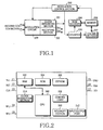
- FIG. 1 shows a structure of a passive RFID tag.
- a tag shown in FIG. 1 is MCRF200 available from Microchip Technology, Inc.
- a modulation circuit 209 is a part for connecting antenna coils (not shown) to RFID circuit elements. As an RFID interrogator (not shown) approaches an RFID tag, according to Faraday's law, the antenna coil generates induced electromotive force through an inductive coupling between the RFID interrogator and the RFID tag. Voltage intensity of the antenna coil varies depending on a modulated signal outputted from the modulation circuit 209.
- a rectifying section 202 rectifies AC voltage of the induced electromotive force in order to supply DC voltage to other components.
- a clock generating section 201 generates a system clock by extracting carrier frequency from a signal transferred from the RFID interrogator. The clock generating section 201 supplies other circuit components of the RFID tag with a baud rate, a modulation rate, and a programming rate.
- a row decoder 204 and a column decoder 207 extract ID data stored in a memory 206 at a clock rate and encode an extracted ID data by means of an NRZ (Non Return to Zero) Direct method, a Differential Biphase method, or a Manchester Biphase method before modulation, thereby generating a serial data stream.
- NRZ Non Return to Zero
- a modulation control section 203 modulates the serial data stream transferred from the decoders 204 and 207 by using a predetermined method, such as an FSK (Frequency Shift keying) method or a PSK (Phase Shift Keying) and the like, and transfers the serial data stream to the modulation circuit 209.
- a counter 205 counts clocks outputted from the clock generating section 201, so as to provide the clocks to the row decoder 204 and the column decoder 207.
- a mobile telephone having a GSM (Global System for Mobile telecommunication) mode generally uses a SIM card for identifying subscribers.
- the SIM card has a small-sized card shape and is used while being set in a slot provided on a rear side of a body of a GSM mode mobile telephone.
- FIG. 2 shows a structure of a conventional SIM card for a mobile terminal.
- a SIM card used for mobile communication systems is defined in GSM 11.11 Standard, GSM 11.12 Standard, and ISO/IEC 7816. In these standard documents, physical characteristics and electrical signals and transmission protocols of the SIM card and a logical model for the SIM card are explained.
- the SIM card has 8 external pins. Contact pins C1, C2, C3, C5, and C6 refer to voltage Vcc, a reset RST, a clock CLK, a ground GND, and program voltage Vpp, respectively.
- a contact pin C7 is an external pin for data input/output I/O and is connected to an antenna for identifying radio frequency. Also, contact pins C4 and C8 RFUs are reserved.
- the SIM card internally has a Read Only Memory (ROM) 304 including an operation system operating the SIM card, a Central Processing Unit (CPU) 300 controlling an SIM card operation, a Random Access Memory (RAM) 302 which is a data processing block, and an Electrically Erasable Programmable Read Only Memory (EEPROM) 306 storing identity information of the SIM card.
- ROM Read Only Memory
- CPU Central Processing Unit
- RAM Random Access Memory
- EEPROM Electrically Erasable Programmable Read Only Memory
- the SIM card is a kind of a smart card. If an RFID tag having functions of the smart card is separately provided for a mobile communication terminal capable of detaching the SIM card, wasteful factors occur. If the SIM card and the RFID tag are separately provided for the mobile communication, it is difficult to manage the RFID tag for service vendors, who provide various services using the SIM card and pursue added value creation through the various services. Accordingly, it is impossible for the service vendors to acquire the expected advantages resulting from employing the RFID tag, which are namely an increase of profit by means of an RFID service, an increase of the number of subscribers, and an expansion of a service range.
- SIM/WIM card which achieves a WIM (Wireless Application Protocol identify Module) function for providing application services is formulated as WAP Provisioning Smart Card WAP-186-PROVSC-20010710-a Version by the WAP forum.
- Toolkit applications providing additional services by dynamically using the SIM card are defined in the GSM 11.14 Standard.
- the above-mentioned forum or standards only defines file structures and protocols for providing application services, and do not define hardware or software protocols accompanied with combination or connection between the RFID tag and the SIM card. Also, the above-mentioned forum or standards do not solve all existing problems.
- EP 1 522 , 955 which falls under Art.
- 54(3) EPC A1 discloses a mobile terminal including an RFID tag. This RFID tag is part of the mobile terminal.
- the mobile includes the RFID tag wherein the main elements of the RFID are implemented with one integrated circuit which is then also part of the circuit board of the terminal. Also according to other embodiments such one-part form of RFID tag and integrated circuit of the mobile terminal is always used. However, it does not disclose a SIM card performing RFID function.
- US 2003/0006 280 A1 discloses a portable terminal apparatus with a contactless IC card function.
- the IC Card function is enabled for utilization during a period of time in particular when an input password matches a registered password.
- a SIM card coupled with an RFID tag is an improvement of a conventional SIM card in view of hardware configuration, logical structure, and operational procedure.
- FIGS. 3 and 4 are block diagrams of a SIM card coupled with an RFID tag according to exemplary embodiments of the present invention.
- FIG. 3 is a view showing the structure of the SIM card coupled with the RFID tag according to a first embodiment of the present invention.
- FIG. 3 several already-known components of the SIM card are not illustrated.
- RFID data shown as a dotted-block in FIG. 3 represent that an RFID memory section can be provided in an EEPROM 404 or in an ROM 410.
- ID (identification) data are generally stored in an EEPROM.
- the SIM card also includes the EEPROM.
- a margin space of the EEPROM can be utilized as a storage space of RFID data. That is, the EEPROM 404 stores RFID data as well as intrinsic data of the SIM card.
- An RFID CODEC section 406 and an RFID modulation section 408 are provided in the ROM 410 of the SIM card.
- the ROM 410 of the SIM card is a digital logic circuit for realizing an operating system by using a digital CODEC and a modulation section.
- a CPU 402 transfers an order to the ROM 410 such that a required function can be carried out.
- RFID data can be processed as another SIM card data.
- functional instruction words such as SELECTION, STATUS, READ BINARY, and UPDATE BINARY, described in "8. Description of the functions" of GSM 11.11 standard document can be used in software capable of operating RFID functions of the SIM card.
- Connection pins C4 and C8, usage of which is now reserved, are connected to an RFID antenna coil (not shown) through a coil connecting section 412 connected to an interrupt section 414. Induced electromotive force is generated from the RFID antenna coil when an RFID interrogator (not shown) approaches the RFID antenna coil and induced electromotive force is transferred to the interrupt section 414 through the coil connecting section 412, thereby creating the interrupt.
- the CPU 402 Upon detecting the interrupt, the CPU 402 recognizes that extracting and processing of RFID data are required.
- the CPU 402 reads RFID data stored in a memory section (EEPROM 404 or ROM 410) and stores RFID data in a RAM 400.
- the CPU 402 controls the RFID CODEC section 406 and the RFID modulation section 408 so as to process RFID data.
- An RFID signal outputted from the RFID modulation section 408 is transmitted to the RFID interrogator through the coil connecting section 412 with a predetermined frequency determined by the RFID system.
- the CPU 402 not only detects the creation of interrupt from the interrupt section 414, but also recognizes a time for carrying out the RFID functions through various manners, such as a software timer.
- RFID functional blocks such as the EEPROM 404, RFID CODEC section 406, and RFID modulation section 408 receive supply voltage Vcc, which is stable voltage of a mobile terminal, through a connection terminal C1 of the SIM card.
- Vcc stable voltage of a mobile terminal
- the clock supplied to a connection pin C3 is typically in a standard range of 1 MHz to 5MHz from a clock supply of the mobile terminal.
- the CPU 402 varies the clock CLK according to the RFID system and transmits the RFID signal by synchronizing the RFID signal with the varied clock CLK.
- FIG. 4 is a view showing a structure of the SIM card coupled with the RFID tag according to a second embodiment of the present invention. In FIG. 4 , several already-known components of the SIM card are not illustrated.
- an RFID CODEC section 508 and an RFID modulation section 510 are provided in the SIM card in such a manner that the RFID CODEC section 508 and the RFID modulation section 510 are separate from a memory section.
- a clock modulation section 516 modulates a clock CLK transmitted from a mobile terminal through a connection pin C3 of the SIM card, thereby generating an RFID clock signal 518 and a SIM clock signal 520.
- the RFID clock signal 518 has a frequency required for operating RFID functional blocks, such as the RFID CODEC section 508 and the RFID modulation section 510.
- the SIM clock signal has a frequency required for operating SIM functional blocks, such as a CPU 500, a RAM 502, a ROM 504, and an EEPROM 506.
- the RFID clock signal 518 can be used as a reference when the CPU 500 finally generates the RFID signal, without using the RFID clock signal 518 for the operation of the above RFID functional blocks.
- the above RFID functional blocks may use the clock signal identical to the clock signal of the SIM functional blocks. That is, the above RFID functional blocks may use the SIM clock signal 520.
- the clock is generated by means of the clock modulation section 516 and is controlled by means of a control signal 522 applied from the CPU 500.
- the CPU 500 reads RFID data stored in the memory section, such as the EEPROM 506 or the ROM 504, and stores RFID data in the RAM 502. In addition, the CPU 500 transfers RFID data to the RFID CODEC section 508 so as to convert RFID data into the RFID signal through the RFID modulation section 510.
- the RFID signal is transferred to a coil connecting section 514 and is propagated to an exterior through an antenna coil (not shown) connected to the coil connecting section 514.
- a logical structure of the SIM card used in a GSM mobile terminal is prescribed in a GSM 11.11 standard document.
- it is required to vary the logical structure of the SIM card.
- the variation may be carried out within a predetermined range capable of maintaining flexibility.
- FIG. 5 is a block view showing the logical structure of the SIM card according to one embodiment of the present invention.
- the logical structure of the SIM card includes a master file (MF), a dedicated file (DF), and an elementary file (EF).
- the MF is selected when the SIM card is initially operated and is designated as a present directory.
- the DF is used for providing multi-functions required for various business services, such a telecom service, a Global System for Mobile communications (GSM), a Digital Cellular System 1800 (DCS1800) or an Interim Standard 41 (IS41).
- GSM Global System for Mobile communications
- DCS1800 Digital Cellular System 1800
- IS41 Interim Standard 41
- the DF has the EF, which stores data utilized for each service.
- the new DF includes a DF RFID for the RFID function.
- An EF 6 stores RFID data for the purpose of the service.
- a file ID "7F2X" is allotted to the DF for new services.
- RFID data is stored in the EF corresponding to the DF having the file ID of 7F2X, it is possible to store data for the RFID service in the conventional SIM logical structure without using conventional instruction words.
- Such files for the RFID service are stored in the EEPROM 406 shown in FIG. 3 and the EEPROM 506 shown in FIG. 4 .
- FIG. 6 is a view showing an EF structure for storing RFID data according to an exemplary embodiment of the present invention.
- the EF is based on GSM standardization, the EF is realized as an extensible file of the SIM logical structure so that conventional software can be continuously used.
- a variable range of an "identifier” may depend on the file ID of the DF. For instance, if the DF RFID has a file ID of 7F2X, the identifier has 6F2X, 6F3X or 6F4X.
- a "structure” is a file structure of the EF. Transparent type, linear fixed type, and cyclic type EFs are standardized. The transparent type EF is adaptable for a sequence of bytes, such as RFID data.
- a "file size” is a size of RFID data to be stored (for example, 4 bytes).
- Software instruction words for controlling RFID data stored in the EF include READ, UPDATE, INVALIDATE, and REHABILITATE, which are based on the standardization of the GSM.
- executive conditions for the instruction words include CHV1 (card holder verification 1) and ADM (administration).
- CHV1 represents a software task allowing a card holder to access thereto
- the ADM represents a software task allowing an administrator of the SIM card to access thereto.
- a mode of the SIM card and an interface between a mobile terminal and the SIM card are varied.
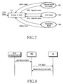
- FIG. 7 is a view showing a mode transition of the SIM card according to one embodiment of the present invention.
- a mode of the SIM card can be shifted into a specific mode or a negotiable mode after transmitting an ATR (answer-to-reset) signal in response to a reset request from the mobile terminal.
- the specific mode is divided into a telecom mode (for example, GSM mode) and an RFID mode.
- Application software of the mobile terminal requests the negotiable mode through a signal exchange between the mobile terminal and the SIM card.
- a mode transition of a smart card into the RFID mode according to a request of the mobile terminal is one example of the negotiable mode.
- the mode transition is displayed by a specific mode byte TA(2) of the ATR signal, which is prescribed in ISO/IEC 7816-3.
- the ATR signal is the sequence of bytes transferred to the mobile terminal from the SIM card as an answer for a reset request of the mobile ' terminal.
- the ATR signal is an asynchronous transmission.
- FIG. 8 is a view showing the signal exchange between the mobile terminal and the SIM card according to one embodiment of the present invention.
- the CPU of the SIM card having the RFID function recognizes an approach of the RFID interrogator, via the interrupt section, the CPU of the SIM card indicates the approach of the RFID interrogator to the CPU of the mobile terminal by using the ATR signal.
- the mobile terminal ME Upon receiving the ATR signal indicating an operation of the RFID function from the SIM card, the mobile terminal ME, grants the RFID function depending on an application program or an operational state of the mobile terminal , so that the SIM card can perform the RFID function.
- the mobile terminal may reject the RFID function.
- the mobile terminal can be designed such that the mobile terminal is converted into an RFID mode when the CPU of the mobile terminal recognizes the approach of the RFID interrogator.
- FIG. 9 is a block view showing a structure of the ATR signal shown in FIG. 8 .
- the ATR signal which is prescribed in ISO/IEC 7816-3, is a combination of bytes transmitted in series. Usage of each byte is prescribed in ISO/IEC 7816-3. In addition, usage of some bytes is reserved.
- the SIM card can indicate the start of the RFID function to the mobile terminal by using the ATR signal.
- the ATR signal including beats (for example, beats having a lower four-beat value of "1111") capable of indicating the RFID mode can be made in the specific mode byte TA(2).
- the specific mode byte TA(2) may be used to indicate that a mode has been already shifted into the RFID mode from the specific mode after a cold reset (that is, when the SIM card having the RFID mode receives a request, which does not relate to the RFID, from the mobile terminal. For example, when the mobile terminal requests the user's ID).
- the specific mode byte TA(2) may be used to indicate the start of the RFID mode as the RFID interrogator approaches the SIM card (that is, notifying of a transition into the RFID mode from a communication mode).
- a bit indicating the RFID mode can be added to the lower four-bits of a TD(i), which is an interface byte.
- TD(i) which is an interface byte.
- FIG. 10 is a schematic view showing a structure of a mobile terminal equipped with an SIM card having an RFID section.
- Reference numeral 900 represents a processor of the mobile terminal ME.
- An example of the processor is a mobile station modem (MSM) chip called “mobile processor” available from the Qualcomm company.
- MSM mobile station modem
- Reference numeral 950 represents the SIM card:
- the SIM card having the RFID section is installed in the mobile terminal in order to signal a mode transition into an RFID mode.
- a CPU 912, a SIM section 914 and an RFID section 916 of the SIM card 950 are only illustrated in FIG. 10 .
- already-known components of the SIM card 950 are not illustrates in FIG. 10 .
- the SIM section 914 is a user information processing section for storing user information and generating a user information signal including user information.
- the user information processing section includes a user information memory section for storing user information and a user program memory section having a program generating a user information signal.
- the user information memory section includes the EEPROM 404 and the user program memory section includes the ROM 410, as shown in FIG. 3 .
- the user information memory section includes the EEPROM 506 and the user program memory section includes the ROM 504 as shown in FIG. 4 .
- the RFID section 916 is an RFID information processing section capable of storing and processing RFID data and generating an RFID signal including RFID data.
- the RFID information processing section includes an RFID information memory section for storing RFID information and an RFID function section for generating the RFID signal.
- the RFID information memory section can be provided in the EEPROM 404 or ROM 410, and the RFID function section includes the RFID CODEC section 406 and the RFID modulation section 408 as shown in FIG. 3 .
- the RFID information memory section can be provided in the EEPROM 506 or ROM 504, and the RFID function section includes the RFID CODEC section 508 and the RFID modulation section 510, as shown in FIG. 4 .
- the CPU 912 is a main calculating section connected to the user information processing section to command the generation of the user information signal so as to transmit the user information signal, and connected to the RFID information processing section to command generation of the RFID signal in order to transmit the RFID signal.
- the CPU 912 corresponds to the CPU 402 shown in FIG. 3 and the CPU 500 shown in FIG. 4 .
- the RFID section 916 of the SIM card 950 installed in the mobile terminal MT detects the approach of the RFID interrogator. Upon detecting the RFID interrogator, the RFID section 916 transfers detecting data to the CPU 912 of the SIM card 950 so that the SIM card 950 recognizes that the RFID function must be carried out. Accordingly, the CPU 912 of the SIM card 950 transmits a signal to the processor 900 of the mobile terminal so as to convert a mode of the mobile terminal into the RFID mode. In addition, a mode of the SIM card 950 is converted into an RFID function mode for performing the RFID function.
- the mobile terminal can provide stable clocks and a stable power supply to the RFID functional blocks, rather than receiving power from the RFID interrogator or providing clocks to the functional blocks that use the coil connecting section and that extract the clocks from a carrier wave signal transmitted from the RFID interrogator, thereby stabilizing the system.
- Conventional systems may become unstable depending on RF feeding environment if carrier wave signals and induced electromotive force are deteriorated.
- the present invention performing the RFID function by utilizing the SIM card has advantages that include:
- the SIM card can be detachably installed in the mobile terminal so as to perform the RFID functions, but the portability and miniaturization of the mobile terminal, which are important matters, are not thereby improved. If the RFID tag is separately fabricated from the SIM card, the mobile terminal may not satisfy the portability and miniaturization requirements.
- the present invention may upgrade the conventional SIM card, so it is possible to create a new demand for the SIM card.
- an RFID technique is provided through the SIM card, an advanced RFID technique can be applied to the conventional mobile communication system. If the RFID tag is fabricated separate from the SIM card, the RFID tag may be fixed in the mobile terminal, so it is difficult to apply the advanced RFID technique to the mobile terminal.
- an earning rate of a service provider providing a service to subscribers by managing the SIM card may increase. This is because the RFID technique, which is a basis for new services, is adopted in the SIM card, making it possible to provide additional techniques based on a conventional payment charge system and a conventional user management system. If the RFID tag is fabricated separately from the SIM card, it is difficult to provide new services that utilize the RFID tag, resulting in a decreased earning rate of the service provider.
Description
- The present invention relates to a mobile terminal having an RFID (radio frequency identification) tag, the usage and importance of which have increased, and a detachable SIM (subscriber identification module), the usage and importance of which have also increased, and more particularly to a circuit in which an RFID tag is integrally coupled with an SIM, a mobile terminal circuit having the circuit and a method for performing an RFID function in a mobile communication terminal.
- An RFID transponder or a tag has been developed in an agriculture department of U.S. National Laboratory to identify livestock. The tag having an electric code capable of identifying an animal is inserted into or attached to the animal. In addition, an interrogator capable of interpreting such electrical code is installed in an animal stable, thereby conveniently checking whether the animal has returned to the stable. The interrogator transmits an RF signal to the tag, and the electric code stored in the tag is returned to the interrogator through a modulator of the tag. This is called a backscatter modulation. An RFID tag has an antenna coil through which a modulation signal is transmitted to the interrogator. Such systems are described in
U.S. Patent Nos. 4,075,632 and4,360,810 . - As RFID techniques make great strides, other techniques for identifying moving objects have been applied to various fields. For example, the techniques have been utilized for vehicles, ocean conveyance containers, or railroad vehicles. Information stored in a tag of such a transportation device is used for a location tracking, a content identification, and so forth. Techniques in relation to such fields are disclosed in
U.S. Patent Nos. 4,739,328 ,4,782,345 ,4,786,907 ,4,816,839 ,4,835,377 , and4,853,705 . - Recently, the RFID technique has been tested in many kinds of fields. A communication system used in such fields has come into the spotlight, owing to wide applicability. For instance, since a mobile communication system has many subscribers, in a case where the mobile communication system employing new techniques such as RFID is industrialized, it is possible to easily make profits. Also, since a current mobile communication is stabilized in the aspect of profitability, vendors request to develop applications capable of making supplementary value.
-
FIG. 1 shows a structure of a passive RFID tag. A tag shown inFIG. 1 is MCRF200 available from Microchip Technology, Inc. - A
modulation circuit 209 is a part for connecting antenna coils (not shown) to RFID circuit elements. As an RFID interrogator (not shown) approaches an RFID tag, according to Faraday's law, the antenna coil generates induced electromotive force through an inductive coupling between the RFID interrogator and the RFID tag. Voltage intensity of the antenna coil varies depending on a modulated signal outputted from themodulation circuit 209. - A rectifying
section 202 rectifies AC voltage of the induced electromotive force in order to supply DC voltage to other components. Aclock generating section 201 generates a system clock by extracting carrier frequency from a signal transferred from the RFID interrogator. Theclock generating section 201 supplies other circuit components of the RFID tag with a baud rate, a modulation rate, and a programming rate. Arow decoder 204 and acolumn decoder 207 extract ID data stored in amemory 206 at a clock rate and encode an extracted ID data by means of an NRZ (Non Return to Zero) Direct method, a Differential Biphase method, or a Manchester Biphase method before modulation, thereby generating a serial data stream. - A
modulation control section 203 modulates the serial data stream transferred from thedecoders modulation circuit 209. Acounter 205 counts clocks outputted from theclock generating section 201, so as to provide the clocks to therow decoder 204 and thecolumn decoder 207. - In a case in which a mobile communication system employs an RFID technique, it is expected to provide various supplementary services suitable for cellular systems.
- In this case, it is absolutely necessary that current RFID equipment are properly combined with current cellular systems. It has already mentioned that an RFID tag (e.g., a card-type RFID tag) is combined with an existing mobile terminal. An example of the RFID tag is disclosed in
Korean Patent laid-open publication No. 2002-0090929 - However, since a generally-used RFID tag is only provided for an existing mobile terminal circuit without modifying it or performing an adaptation process, the problem occurs that such an RFID tag is not adaptable for the miniaturization and portability of the existing mobile terminal which are essential features of a mobile terminal.
- Meanwhile, a mobile telephone having a GSM (Global System for Mobile telecommunication) mode generally uses a SIM card for identifying subscribers. The SIM card has a small-sized card shape and is used while being set in a slot provided on a rear side of a body of a GSM mode mobile telephone.
-
FIG. 2 shows a structure of a conventional SIM card for a mobile terminal. - A SIM card used for mobile communication systems, such as GSM systems, is defined in GSM 11.11 Standard, GSM 11.12 Standard, and ISO/IEC 7816. In these standard documents, physical characteristics and electrical signals and transmission protocols of the SIM card and a logical model for the SIM card are explained. The SIM card has 8 external pins. Contact pins C1, C2, C3, C5, and C6 refer to voltage Vcc, a reset RST, a clock CLK, a ground GND, and program voltage Vpp, respectively. A contact pin C7 is an external pin for data input/output I/O and is connected to an antenna for identifying radio frequency. Also, contact pins C4 and C8 RFUs are reserved.
- The SIM card internally has a Read Only Memory (ROM) 304 including an operation system operating the SIM card, a Central Processing Unit (CPU) 300 controlling an SIM card operation, a Random Access Memory (RAM) 302 which is a data processing block, and an Electrically Erasable Programmable Read Only Memory (EEPROM) 306 storing identity information of the SIM card.
- The SIM card is a kind of a smart card. If an RFID tag having functions of the smart card is separately provided for a mobile communication terminal capable of detaching the SIM card, wasteful factors occur. If the SIM card and the RFID tag are separately provided for the mobile communication, it is difficult to manage the RFID tag for service vendors, who provide various services using the SIM card and pursue added value creation through the various services. Accordingly, it is impossible for the service vendors to acquire the expected advantages resulting from employing the RFID tag, which are namely an increase of profit by means of an RFID service, an increase of the number of subscribers, and an expansion of a service range.
- There exists a method in which the SIM card provides additional functions besides a primary function for authenticating mobile terminal users. For instance, a SIM/WIM card which achieves a WIM (Wireless Application Protocol identify Module) function for providing application services is formulated as WAP Provisioning Smart Card WAP-186-PROVSC-20010710-a Version by the WAP forum. Toolkit applications providing additional services by dynamically using the SIM card are defined in the GSM 11.14 Standard.
- The above-mentioned forum or standards only defines file structures and protocols for providing application services, and do not define hardware or software protocols accompanied with combination or connection between the RFID tag and the SIM card. Also, the above-mentioned forum or standards do not solve all existing problems.
-
EP 1 522955 -
US 2003/0006 280 A1 discloses a portable terminal apparatus with a contactless IC card function. The IC Card function is enabled for utilization during a period of time in particular when an input password matches a registered password. Nothing is disclosed about an SIM Card performing RFID function. - It is an object of the present invention to provide a mobile terminal and a method for performing a RFID function in a mobile terminal which are improved to provide a SIM card coupled with a RFID tag.
- This object is solved by the independent claims.
- Preferred embodiments are defined in the dependent claims.
- The above object, aspects and other features and advantages of the present invention will be more apparent from the following detailed description taken in conjunction with the accompanying drawings, in which:
-
FIG. 1 is a block diagram of a conventional radio frequency identification, RFID, tag; -
FIG. 2 is a block diagram of a conventional SIM card; -
FIG. 3 is a block diagram of an SIM card coupled with an RFID tag according to a first embodiment of the present invention; -
FIG. 4 is a block diagram of an SIM card coupled with an RFID tag according to a second embodiment of the present invention; -
FIG. 5 is a block view showing a logical structure of an SIM card according to one embodiment of the present invention; -
FIG. 6 is a view showing an EF structure for storing RFID data according to one embodiment of the present invention; -
FIG. 7 is a view showing a mode transition of an SIM card according to one embodiment of the present invention; -
FIG. 8 is a view showing a signal exchange between a mobile terminal and a SIM card according to one embodiment of the present invention; -
FIG. 9 is a block view showing a structure of an ATR signal shown inFIG. 8 ; and -
FIG. 10 is a schematic view showing a structure of a mobile terminal equipped with a SIM card having an RFID section. - Hereinafter, preferred embodiments of the present invention will be described with reference to the accompanying drawings. Although certain functions, such as elements of a specific circuit, are specifically defined in the following description of the present invention, it will be obvious to those skilled in the art that such definitions of functions are merely to improve understanding of the present invention and that the present invention can be carried out without such specific elements. Also, in the following description of the present invention, the same reference numerals are used to designate the same or similar components and a detailed description of known functions and configurations incorporated herein are omitted to avoid making the subject matter of the present invention unclear.
- A SIM card coupled with an RFID tag is an improvement of a conventional SIM card in view of hardware configuration, logical structure, and operational procedure.
-
FIGS. 3 and 4 are block diagrams of a SIM card coupled with an RFID tag according to exemplary embodiments of the present invention. -
FIG. 3 is a view showing the structure of the SIM card coupled with the RFID tag according to a first embodiment of the present invention. InFIG. 3 , several already-known components of the SIM card are not illustrated. In addition, RFID data shown as a dotted-block inFIG. 3 represent that an RFID memory section can be provided in anEEPROM 404 or in anROM 410. - In a conventional RFID tag, ID (identification) data are generally stored in an EEPROM. However, the SIM card also includes the EEPROM. Thus, a margin space of the EEPROM can be utilized as a storage space of RFID data. That is, the
EEPROM 404 stores RFID data as well as intrinsic data of the SIM card. - An
RFID CODEC section 406 and anRFID modulation section 408 are provided in theROM 410 of the SIM card. TheROM 410 of the SIM card is a digital logic circuit for realizing an operating system by using a digital CODEC and a modulation section. - A
CPU 402 transfers an order to theROM 410 such that a required function can be carried out. At this time, since RFID data is stored based on a logical structure of a conventional SIM card, RFID data can be processed as another SIM card data. In other words, functional instruction words, such as SELECTION, STATUS, READ BINARY, and UPDATE BINARY, described in "8. Description of the functions" of GSM 11.11 standard document can be used in software capable of operating RFID functions of the SIM card. - Connection pins C4 and C8, usage of which is now reserved, are connected to an RFID antenna coil (not shown) through a
coil connecting section 412 connected to an interruptsection 414. Induced electromotive force is generated from the RFID antenna coil when an RFID interrogator (not shown) approaches the RFID antenna coil and induced electromotive force is transferred to the interruptsection 414 through thecoil connecting section 412, thereby creating the interrupt. Upon detecting the interrupt, theCPU 402 recognizes that extracting and processing of RFID data are required. Thus, theCPU 402 reads RFID data stored in a memory section (EEPROM 404 or ROM 410) and stores RFID data in aRAM 400. In addition, theCPU 402 controls theRFID CODEC section 406 and theRFID modulation section 408 so as to process RFID data. An RFID signal outputted from theRFID modulation section 408 is transmitted to the RFID interrogator through thecoil connecting section 412 with a predetermined frequency determined by the RFID system. - In addition, the
CPU 402 not only detects the creation of interrupt from the interruptsection 414, but also recognizes a time for carrying out the RFID functions through various manners, such as a software timer. - When seeing the first embodiment of the present invention in view of usable power, RFID functional blocks, such as the
EEPROM 404,RFID CODEC section 406, andRFID modulation section 408 receive supply voltage Vcc, which is stable voltage of a mobile terminal, through a connection terminal C1 of the SIM card. Thus, a problem caused by a conventional power supply of induced electromotive force, which is unstable depending on peripheral environment, can be solved. - When seeing the first embodiment of the present invention in view of a clock CLK, the clock supplied to a connection pin C3 is typically in a standard range of 1 MHz to 5MHz from a clock supply of the mobile terminal. When the RFID signal is transferred to the
coil connecting section 412, theCPU 402 varies the clock CLK according to the RFID system and transmits the RFID signal by synchronizing the RFID signal with the varied clock CLK. -
FIG. 4 is a view showing a structure of the SIM card coupled with the RFID tag according to a second embodiment of the present invention. InFIG. 4 , several already-known components of the SIM card are not illustrated. - Referring to
FIG. 4 , anRFID CODEC section 508 and anRFID modulation section 510 are provided in the SIM card in such a manner that theRFID CODEC section 508 and theRFID modulation section 510 are separate from a memory section. - A
clock modulation section 516 modulates a clock CLK transmitted from a mobile terminal through a connection pin C3 of the SIM card, thereby generating anRFID clock signal 518 and aSIM clock signal 520. TheRFID clock signal 518 has a frequency required for operating RFID functional blocks, such as theRFID CODEC section 508 and theRFID modulation section 510. The SIM clock signal has a frequency required for operating SIM functional blocks, such as aCPU 500, aRAM 502, aROM 504, and anEEPROM 506. - Selectively, the
RFID clock signal 518 can be used as a reference when theCPU 500 finally generates the RFID signal, without using theRFID clock signal 518 for the operation of the above RFID functional blocks. In this case, the above RFID functional blocks may use the clock signal identical to the clock signal of the SIM functional blocks. That is, the above RFID functional blocks may use theSIM clock signal 520. The clock is generated by means of theclock modulation section 516 and is controlled by means of acontrol signal 522 applied from theCPU 500. - The
CPU 500 reads RFID data stored in the memory section, such as theEEPROM 506 or theROM 504, and stores RFID data in theRAM 502. In addition, theCPU 500 transfers RFID data to theRFID CODEC section 508 so as to convert RFID data into the RFID signal through theRFID modulation section 510. The RFID signal is transferred to acoil connecting section 514 and is propagated to an exterior through an antenna coil (not shown) connected to thecoil connecting section 514. - A logical structure of the SIM card used in a GSM mobile terminal is prescribed in a GSM 11.11 standard document. In order to provide the RFID functions according to the present invention, it is required to vary the logical structure of the SIM card. However, the variation may be carried out within a predetermined range capable of maintaining flexibility.
-
FIG. 5 is a block view showing the logical structure of the SIM card according to one embodiment of the present invention. - The logical structure of the SIM card includes a master file (MF), a dedicated file (DF), and an elementary file (EF). The MF is selected when the SIM card is initially operated and is designated as a present directory. The DF is used for providing multi-functions required for various business services, such a telecom service, a Global System for Mobile communications (GSM), a Digital Cellular System 1800 (DCS1800) or an Interim Standard 41 (IS41). The DF has the EF, which stores data utilized for each service.
- In order to realize the present invention, a new DF and a new EF corresponding to the new DF are added to the conventional SIM logical system. As shown in
FIG. 5 , the new DF includes a DFRFID for the RFID function. An EF6 stores RFID data for the purpose of the service. - In the SIM logical system, a file ID "7F2X" is allotted to the DF for new services. Thus, by storing RFID data in the EF corresponding to the DF having the file ID of 7F2X, it is possible to store data for the RFID service in the conventional SIM logical structure without using conventional instruction words. Such files for the RFID service are stored in the
EEPROM 406 shown inFIG. 3 and theEEPROM 506 shown inFIG. 4 . -
FIG. 6 is a view showing an EF structure for storing RFID data according to an exemplary embodiment of the present invention. - Since the EF is based on GSM standardization, the EF is realized as an extensible file of the SIM logical structure so that conventional software can be continuously used.
- A variable range of an "identifier" may depend on the file ID of the DF. For instance, if the DFRFID has a file ID of 7F2X, the identifier has 6F2X, 6F3X or 6F4X. A "structure" is a file structure of the EF. Transparent type, linear fixed type, and cyclic type EFs are standardized. The transparent type EF is adaptable for a sequence of bytes, such as RFID data.
- A "file size" is a size of RFID data to be stored (for example, 4 bytes). Software instruction words for controlling RFID data stored in the EF include READ, UPDATE, INVALIDATE, and REHABILITATE, which are based on the standardization of the GSM. In addition, executive conditions for the instruction words include CHV1 (card holder verification 1) and ADM (administration). The CHV1 represents a software task allowing a card holder to access thereto, and the ADM represents a software task allowing an administrator of the SIM card to access thereto.
- By providing the RFID function to the conventional SIM card, a mode of the SIM card and an interface between a mobile terminal and the SIM card are varied.
-
FIG. 7 is a view showing a mode transition of the SIM card according to one embodiment of the present invention. - A mode of the SIM card can be shifted into a specific mode or a negotiable mode after transmitting an ATR (answer-to-reset) signal in response to a reset request from the mobile terminal. The specific mode is divided into a telecom mode (for example, GSM mode) and an RFID mode. Application software of the mobile terminal requests the negotiable mode through a signal exchange between the mobile terminal and the SIM card. A mode transition of a smart card into the RFID mode according to a request of the mobile terminal is one example of the negotiable mode.
- The mode transition is displayed by a specific mode byte TA(2) of the ATR signal, which is prescribed in ISO/IEC 7816-3. The ATR signal is the sequence of bytes transferred to the mobile terminal from the SIM card as an answer for a reset request of the mobile ' terminal. The ATR signal is an asynchronous transmission.
-
FIG. 8 is a view showing the signal exchange between the mobile terminal and the SIM card according to one embodiment of the present invention. - When the CPU of the SIM card having the RFID function recognizes an approach of the RFID interrogator, via the interrupt section, the CPU of the SIM card indicates the approach of the RFID interrogator to the CPU of the mobile terminal by using the ATR signal. Upon receiving the ATR signal indicating an operation of the RFID function from the SIM card, the mobile terminal ME, grants the RFID function depending on an application program or an operational state of the mobile terminal , so that the SIM card can perform the RFID function. In addition, if it is required that mobile terminal request a primary function of the SIM card, that is, when it is required to primarily request a user's identification for a communication system or when the mobile terminal cannot perform the RFID function, the mobile terminal may reject the RFID function. In addition, without considering the priority, the mobile terminal can be designed such that the mobile terminal is converted into an RFID mode when the CPU of the mobile terminal recognizes the approach of the RFID interrogator.
-
FIG. 9 is a block view showing a structure of the ATR signal shown inFIG. 8 . - The ATR signal, which is prescribed in ISO/IEC 7816-3, is a combination of bytes transmitted in series. Usage of each byte is prescribed in ISO/IEC 7816-3. In addition, usage of some bytes is reserved. Thus, the SIM card can indicate the start of the RFID function to the mobile terminal by using the ATR signal. For instance, the ATR signal including beats (for example, beats having a lower four-beat value of "1111") capable of indicating the RFID mode can be made in the specific mode byte TA(2). The specific mode byte TA(2) may be used to indicate that a mode has been already shifted into the RFID mode from the specific mode after a cold reset (that is, when the SIM card having the RFID mode receives a request, which does not relate to the RFID, from the mobile terminal. For example, when the mobile terminal requests the user's ID). In addition, the specific mode byte TA(2) may be used to indicate the start of the RFID mode as the RFID interrogator approaches the SIM card (that is, notifying of a transition into the RFID mode from a communication mode).
- According to another embodiment of the present invention, a bit indicating the RFID mode can be added to the lower four-bits of a TD(i), which is an interface byte. According to the standardization of ISO/IEC 7816-3, lower four-bits of the TD(i) and TA(2) are defined as a parameter T, wherein usage of some parameters (T= 5 to 13) is reserved to use them in the future. Therefore, usage of some T values for the purpose of the RFID does not violate the standardization of ISO/IEC 7816-3, so that the SIM card can be flexibly used in a conventional system.
-
FIG. 10 is a schematic view showing a structure of a mobile terminal equipped with an SIM card having an RFID section. -
Reference numeral 900 represents a processor of the mobile terminal ME. An example of the processor is a mobile station modem (MSM) chip called "mobile processor" available from the Qualcomm company. -
Reference numeral 950 represents the SIM card: The SIM card having the RFID section is installed in the mobile terminal in order to signal a mode transition into an RFID mode. To this end, aCPU 912, aSIM section 914 and anRFID section 916 of theSIM card 950 are only illustrated inFIG. 10 . Already-known components of theSIM card 950 are not illustrates inFIG. 10 . - The
SIM section 914 is a user information processing section for storing user information and generating a user information signal including user information. In addition, the user information processing section includes a user information memory section for storing user information and a user program memory section having a program generating a user information signal. The user information memory section includes theEEPROM 404 and the user program memory section includes theROM 410, as shown inFIG. 3 . In addition, the user information memory section includes theEEPROM 506 and the user program memory section includes theROM 504 as shown inFIG. 4 . - The
RFID section 916 is an RFID information processing section capable of storing and processing RFID data and generating an RFID signal including RFID data. In addition, the RFID information processing section includes an RFID information memory section for storing RFID information and an RFID function section for generating the RFID signal. The RFID information memory section can be provided in theEEPROM 404 orROM 410, and the RFID function section includes theRFID CODEC section 406 and theRFID modulation section 408 as shown inFIG. 3 . In addition, the RFID information memory section can be provided in theEEPROM 506 orROM 504, and the RFID function section includes theRFID CODEC section 508 and theRFID modulation section 510, as shown inFIG. 4 . - The
CPU 912 is a main calculating section connected to the user information processing section to command the generation of the user information signal so as to transmit the user information signal, and connected to the RFID information processing section to command generation of the RFID signal in order to transmit the RFID signal. TheCPU 912 corresponds to theCPU 402 shown inFIG. 3 and theCPU 500 shown inFIG. 4 . - When an RFID interrogator (not shown) approaches the mobile terminal MT within a predetermined distance, the
RFID section 916 of theSIM card 950 installed in the mobile terminal MT detects the approach of the RFID interrogator. Upon detecting the RFID interrogator, theRFID section 916 transfers detecting data to theCPU 912 of theSIM card 950 so that theSIM card 950 recognizes that the RFID function must be carried out. Accordingly, theCPU 912 of theSIM card 950 transmits a signal to theprocessor 900 of the mobile terminal so as to convert a mode of the mobile terminal into the RFID mode. In addition, a mode of theSIM card 950 is converted into an RFID function mode for performing the RFID function. - According to the present invention, the mobile terminal can provide stable clocks and a stable power supply to the RFID functional blocks, rather than receiving power from the RFID interrogator or providing clocks to the functional blocks that use the coil connecting section and that extract the clocks from a carrier wave signal transmitted from the RFID interrogator, thereby stabilizing the system. Conventional systems may become unstable depending on RF feeding environment if carrier wave signals and induced electromotive force are deteriorated.
- As described above, the present invention performing the RFID function by utilizing the SIM card has advantages that include:
- First, the SIM card can be detachably installed in the mobile terminal so as to perform the RFID functions, but the portability and miniaturization of the mobile terminal, which are important matters, are not thereby improved. If the RFID tag is separately fabricated from the SIM card, the mobile terminal may not satisfy the portability and miniaturization requirements.
- Second, in a functional aspect, the present invention may upgrade the conventional SIM card, so it is possible to create a new demand for the SIM card.
- Third, since an RFID technique is provided through the SIM card, an advanced RFID technique can be applied to the conventional mobile communication system. If the RFID tag is fabricated separate from the SIM card, the RFID tag may be fixed in the mobile terminal, so it is difficult to apply the advanced RFID technique to the mobile terminal.
- Fourth, an earning rate of a service provider providing a service to subscribers by managing the SIM card may increase. This is because the RFID technique, which is a basis for new services, is adopted in the SIM card, making it possible to provide additional techniques based on a conventional payment charge system and a conventional user management system. If the RFID tag is fabricated separately from the SIM card, it is difficult to provide new services that utilize the RFID tag, resulting in a decreased earning rate of the service provider.
- While the present invention has been shown and described with reference to certain preferred embodiments thereof, it will be understood by those skilled in the art that various changes in form and details may be made therein without departing from the scope of the invention as defined by the appended claims.
Claims (19)
- A mobile terminal comprising:a subscriber identification module, SIM, card (950) including a user information processing section (914) for storing user information and generating a user information signal including user information,the SIM card further comprising:a radio frequency identification, RFID, information processing section (916; 404, 410, 506, 504) as a RFID tag for storing RFID data and generating a RFID signal including the RFID data, anda main calculating section (912; 402, 500) connected to the user information processing section in order to control generation and transmission of the user information signal, and connected to the RFID information processing section (916) in order to command generation and transmission of the RFID signal;the mobile terminal further comprising:a processor (900) in communication with the SIM card (950) so as to grant or reject a RFID function of the SIM card.
- The mobile terminal as claimed in claim 1, wherein the SIM card (950) including the user information processing section (914) includes a user information memory section (404) for storing user information and a user program memory section (410) including a program for generating the user information signal.
- The mobile terminal as claimed in claim 1 or 2, wherein the SIM card (950) including the RFID information processing section (916) includes an RFID information memory section (404, 410; 504, 506) for storing RFID information and an RFID function section (406, 408; 508, 510) for generating the RFID signal.
- The mobile terminal as claimed in claim 1, wherein the SIM card (950) including the user information processing section (914) includes a user information memory section (404) for storing user information and a user program memory section (410) for storing a program generating a signal having the user information, and the RFID information processing section (916) includes an RFID information memory section for storing RFID information and an RFID function section for generating the RFID signal.
- The mobile terminal as claimed in claim 3 or 4, wherein the SIM card (950) including the user information memory section (404) includes the RFID information memory section (408, 410).
- The mobile terminal as claimed in claim 5, wherein the SIM card (950) including the user program memory section (410) includes the RFID function section (406, 408).
- The mobile terminal as claimed in claim 3, wherein the SIM card (950) including the RFID function section (406, 408, 508, 510) includes an RFID CODEC section (406, 508) and an RFID modulation section (408, 510).
- The mobile terminal as claimed in one of claims 1 to 7, the SIM card (950) further comprising a plurality of external pins, including a power pin, a clock pin, and a data input/output pin.
- The mobile terminal as claimed in claim 8, wherein the SIM card (950) including one of the plurality of external pins is connected to an RFID antenna.
- The mobile terminal as claimed in claim 9, wherein the SIM card (950) including the main calculating section (912, 402, 500) transmits the RFID signal to the RFID antenna connected to the SIM card.
- The mobile terminal as claimed in one of claims 1 to 10, the SIM card (950) further comprising an interrupt section (414, 512) which is connected to the main calculating section (900, 402, 500) and which provides to the main calculating section an interrupt signal to indicate an RFID mode.
- The mobile terminal as claimed in one of claims 1 to 11, the SIM card (950) further comprising a clock generator for providing RFID clocks to the RFID information processing section.
- The mobile terminal as claimed in claim 12, wherein the SIM card (950) including the main calculating section (900, 402, 500) generates a control signal for controlling the clock generator.
- The mobile terminal as claimed in one of claims 1 to 11, the SIM card (950) further comprising a clock generator for providing RFID clocks to the main calculating section.
- A method for performing an RFID function in a mobile terminal equipped with a SIM card (950) having an RFID tag; the method comprising:detecting (810) an approach of an RFID interrogator by using the RFID tag;requesting (820) a CPU of the SIM card (950) to perform the RFID function by utilizing the RFID tag;transmitting a mode transition signal to a processor (900) of the mobile terminal by using the CPU of the SIM card (950) to indicate a mode transition into an RFID mode; andperforming the RFID function by using the SIM card (950) after transmitting the mode transition signal.
- The method as claimed in claim 15, further comprising a step of transmitting a response signal from the processor (900) of the mobile terminal to the CPU of the SIM card (950) in response to the mode transition signal.
- The method as claimed in claim 15 or 16, wherein the mode transition signal includes a flag representing an execution of the RFID function.
- The method as claimed in claim 16, wherein the response signal includes information representing a grant of the RFID function.
- The method as claimed in claim 16, wherein the response signal includes information representing a rejection of the RFID function.
Applications Claiming Priority (2)
| Application Number | Priority Date | Filing Date | Title |
|---|---|---|---|
| KR2003085300 | 2003-11-27 | ||
| KR1020030085300A KR100566260B1 (en) | 2003-11-27 | 2003-11-27 | Mobile terminal integrated with a radio frequency identification transponder and smart card and radio frequency identification method thereof |
Publications (3)
| Publication Number | Publication Date |
|---|---|
| EP1536573A2 EP1536573A2 (en) | 2005-06-01 |
| EP1536573A3 EP1536573A3 (en) | 2007-08-22 |
| EP1536573B1 true EP1536573B1 (en) | 2011-05-11 |
Family
ID=34464765
Family Applications (1)
| Application Number | Title | Priority Date | Filing Date |
|---|---|---|---|
| EP04027779A Expired - Fee Related EP1536573B1 (en) | 2003-11-27 | 2004-11-23 | Mobile terminal having smart card coupled with RFID tag and method for performing RFID function in such mobile terminal |
Country Status (5)
| Country | Link |
|---|---|
| US (1) | US7374100B2 (en) |
| EP (1) | EP1536573B1 (en) |
| JP (1) | JP2005166047A (en) |
| KR (1) | KR100566260B1 (en) |
| CN (1) | CN100342393C (en) |
Cited By (8)
| Publication number | Priority date | Publication date | Assignee | Title |
|---|---|---|---|---|
| US8275364B2 (en) | 2008-01-04 | 2012-09-25 | Logomotion, S.R.O. | Systems and methods for contactless payment authorization |
| US8406809B2 (en) | 2009-05-03 | 2013-03-26 | Logomotion, S.R.O. | Configuration with the payment button in the mobile communication device, the way the payment process is started |
| US8500008B2 (en) | 2009-04-24 | 2013-08-06 | Logomotion, S.R.O | Method and system of electronic payment transaction, in particular by using contactless payment means |
| US8737983B2 (en) | 2008-03-25 | 2014-05-27 | Logomotion, S.R.O. | Method, connection and data carrier to perform repeated operations on the key-board of mobile communication device |
| US8799084B2 (en) | 2008-09-19 | 2014-08-05 | Logomotion, S.R.O. | Electronic payment application system and payment authorization method |
| US9054408B2 (en) | 2008-08-29 | 2015-06-09 | Logomotion, S.R.O. | Removable card for a contactless communication, its utilization and the method of production |
| US9081997B2 (en) | 2008-10-15 | 2015-07-14 | Logomotion, S.R.O. | Method of communication with the POS terminal, the frequency converter for the post terminal |
| US9098845B2 (en) | 2008-09-19 | 2015-08-04 | Logomotion, S.R.O. | Process of selling in electronic shop accessible from the mobile communication device |
Families Citing this family (49)
| Publication number | Priority date | Publication date | Assignee | Title |
|---|---|---|---|---|
| WO2004114239A2 (en) * | 2003-06-13 | 2004-12-29 | Wildseed Ltd. | Emulated radio frequency identification |
| EP1725977B1 (en) | 2004-03-19 | 2009-04-15 | Nokia Corporation | Detector logic and radio identification device and method for enhancing terminal operations |
| KR101051703B1 (en) | 2004-08-09 | 2011-07-25 | 삼성전자주식회사 | Integrated circuit card and integrated circuit card system with suspend / reset function |
| US7356539B2 (en) | 2005-04-04 | 2008-04-08 | Research In Motion Limited | Policy proxy |
| US8198985B2 (en) | 2005-05-31 | 2012-06-12 | Amtech Systems, LLC | Automatic mode detection in a dual operating mode RFID tag |
| NO324406B1 (en) * | 2005-06-20 | 2007-10-08 | Telenor Asa | SIM RFID reader with WLAN access |
| KR101246343B1 (en) * | 2005-09-06 | 2013-03-21 | 엘지전자 주식회사 | A Mobile Phone Equipped with RFID Tag and Thereof Method for Controlling Access of RFID Reader |
| CN100527159C (en) * | 2005-10-31 | 2009-08-12 | 深圳华为通信技术有限公司 | Storage card and terminal equipment combining storage card |
| ATE482529T1 (en) * | 2005-12-30 | 2010-10-15 | Nokia Corp | METHOD AND DEVICE FOR EMULATING MULTIPLE RFID LABELS USING A SINGLE MOBILE ELECTRONIC DEVICE |
| KR100756179B1 (en) * | 2006-01-09 | 2007-09-05 | 주식회사 팬택 | A mobile communication terminal having a active rfid transponer |
| KR100738923B1 (en) * | 2006-04-24 | 2007-07-12 | 에스케이 텔레콤주식회사 | Smart card having zigbee module in financial settlement module or subscriber identification module and mobile communication terminal having same |
| US9466057B2 (en) * | 2006-05-04 | 2016-10-11 | First Data Corporation | RF presentation instrument with sensor control |
| US7966263B2 (en) * | 2006-05-04 | 2011-06-21 | First Data Corporation | Wireless phone RF presentation instrument with sensor control |
| KR100889562B1 (en) * | 2006-05-10 | 2009-03-23 | 한국전자통신연구원 | System with Shared Power Amplifier for Mobile Communication Terminal with Mobile RFID Function |
| US7690579B2 (en) * | 2006-07-13 | 2010-04-06 | Research In Motion Limited | Answer to reset (ATR) pushing |
| KR100912076B1 (en) | 2006-07-26 | 2009-08-12 | 한국전자통신연구원 | Apparatus and method for Integrated Reader and Tag |
| US7757943B2 (en) | 2006-08-29 | 2010-07-20 | Metavante Corporation | Combined payment/access-control instrument |
| US20080090595A1 (en) * | 2006-10-11 | 2008-04-17 | Sony Ericsson Mobile Communications Ab | Near field communication for profile change in switching network acess |
| US7667574B2 (en) * | 2006-12-14 | 2010-02-23 | Corning Cable Systems, Llc | Signal-processing systems and methods for RFID-tag signals |
| FR2912591B1 (en) * | 2007-02-12 | 2009-05-01 | Oberthur Card Syst Sa | METHOD AND DEVICE FOR CONTROLLING THE EXECUTION OF AT LEAST ONE FUNCTION IN A SHORT-RANGE WIRELESS COMMUNICATION MODULE OF A MOBILE DEVICE. |
| KR100823678B1 (en) * | 2007-02-12 | 2008-04-18 | 주식회사 와이즈캐치 | Contactless information processor |
| KR101372153B1 (en) * | 2007-06-04 | 2014-03-10 | 엘지이노텍 주식회사 | Smart card |
| KR101382940B1 (en) * | 2007-08-14 | 2014-04-08 | 엘지이노텍 주식회사 | Smart card |
| DE102007039226A1 (en) | 2007-08-20 | 2009-02-26 | Giesecke & Devrient Gmbh | Real-time measurement on a portable data carrier |
| US8157178B2 (en) | 2007-10-19 | 2012-04-17 | First Data Corporation | Manufacturing system to produce contactless devices with switches |
| KR101418249B1 (en) * | 2007-11-20 | 2014-07-11 | 삼성전자주식회사 | Terminal having RF ID function and method for processing information using the same |
| US8831220B2 (en) * | 2007-11-30 | 2014-09-09 | Battelle Energy Alliance, Llc | Processing module operating methods, processing modules, and communications systems |
| DE102008013664A1 (en) * | 2008-03-11 | 2009-09-24 | T-Mobile International Ag | Arrangement and method for operating a SIM card |
| US20090287589A1 (en) * | 2008-05-16 | 2009-11-19 | Fivel Steven E | Mobile, compact communication device including rfid |
| KR101479655B1 (en) * | 2008-09-12 | 2015-01-06 | 삼성전자주식회사 | Method and system for security of portable terminal |
| SK288757B6 (en) * | 2008-09-19 | 2020-05-04 | Smk Kk | System and method for contactless payment authorization |
| CN101685491B (en) * | 2008-09-27 | 2011-08-24 | 佛山市顺德区汉达精密电子科技有限公司 | Portable electronic equipment and mobile RFID reader |
| US8269609B2 (en) * | 2008-12-11 | 2012-09-18 | At&T Intellectual Property I, Lp | Devices, systems and methods for portable device location |
| CN101765242A (en) * | 2008-12-25 | 2010-06-30 | 深圳富泰宏精密工业有限公司 | User identification card and connector thereof as well as portable communication device provided with connector |
| SK500092009A3 (en) * | 2009-02-27 | 2010-09-07 | Logomotion, S. R. O. | Computer mouse for data transmission, preferably at electronic payment, method for data transmission |
| KR101555637B1 (en) * | 2009-03-27 | 2015-09-24 | 삼성전자주식회사 | Smart card |
| SK288521B6 (en) | 2009-07-08 | 2017-12-04 | Smk Corporation | Method and system for entering the PIN code at non-cash payments, carrier PIN code |
| US20110063091A1 (en) * | 2009-09-11 | 2011-03-17 | Hynix Semiconductor Inc. | Radio frequency identification system |
| EP2317337A1 (en) * | 2009-11-03 | 2011-05-04 | Gemalto SA | Contactless transfer system for personal data |
| CN101847090B (en) * | 2010-02-05 | 2014-11-12 | 广州市花都区中山大学国光电子与通信研究院 | Special microcontroller for RFID (Radio Frequency Identification) intelligent card |
| US8819792B2 (en) * | 2010-04-29 | 2014-08-26 | Blackberry Limited | Assignment and distribution of access credentials to mobile communication devices |
| KR101178514B1 (en) * | 2010-08-27 | 2012-08-30 | 한국광성전자 주식회사 | Radio communication interface system and method |
| WO2012036567A1 (en) * | 2010-09-13 | 2012-03-22 | Trident Rfid Pty Ltd | System and method for updating parameters and firmware on rfid readers |
| US8532619B2 (en) * | 2010-12-30 | 2013-09-10 | Samsung Electronics Co., Ltd. | System for authorizing the use of communication devices by proximity |
| JP2013105280A (en) * | 2011-11-11 | 2013-05-30 | Dainippon Printing Co Ltd | Ic card and computer program for ic card |
| CN102724642B (en) * | 2012-06-12 | 2015-02-25 | 中国联合网络通信集团有限公司 | Service message processing method, smart card and terminal equipment |
| US9996871B2 (en) | 2014-10-15 | 2018-06-12 | Toshiba Global Commerce Solutions Holdings Corporation | Systems, methods, and mobile computing devices for purchase of items and delivery to a location within a predetermined communication range |
| CN104504413B (en) * | 2014-11-19 | 2018-01-02 | 上海大学 | A kind of RFID antenna deployment system monitored in real time for warehouse and method |
| FR3035252B1 (en) | 2015-04-14 | 2017-04-28 | Stmicroelectronics Rousset | METHOD FOR MANAGING INFORMATION COMMUNICATION BETWEEN AN NFC CONTROLLER AND A SECURE ELEMENT IN AN APPARATUS, AND CORRESPONDING NFC APPARATUS AND CONTROLLER |
Family Cites Families (27)
| Publication number | Priority date | Publication date | Assignee | Title |
|---|---|---|---|---|
| US4075632A (en) | 1974-08-27 | 1978-02-21 | The United States Of America As Represented By The United States Department Of Energy | Interrogation, and detection system |
| US4360810A (en) | 1981-01-19 | 1982-11-23 | The United States Of America As Represented By The United States Department Of Energy | Multichannel homodyne receiver |
| US4739328A (en) | 1986-07-14 | 1988-04-19 | Amtech Corporation | System for identifying particular objects |
| US4786907A (en) | 1986-07-14 | 1988-11-22 | Amtech Corporation | Transponder useful in a system for identifying objects |
| US4782345A (en) | 1986-07-29 | 1988-11-01 | Amtech Corporation | Transponder antenna |
| US4835377A (en) | 1987-06-10 | 1989-05-30 | Brown Richard R | Programmer for identification system |
| US4816839A (en) | 1987-12-18 | 1989-03-28 | Amtech Corporation | Transponder antenna |
| US4853705A (en) | 1988-05-11 | 1989-08-01 | Amtech Technology Corporation | Beam powered antenna |
| US5394439A (en) * | 1991-11-12 | 1995-02-28 | Comsat Corporation | Bisdn compatible modem codec for digital information communication system |
| US5640002A (en) * | 1995-08-15 | 1997-06-17 | Ruppert; Jonathan Paul | Portable RF ID tag and barcode reader |
| US5943624A (en) | 1996-07-15 | 1999-08-24 | Motorola, Inc. | Contactless smartcard for use in cellular telephone |
| JPH1051349A (en) * | 1996-08-01 | 1998-02-20 | Nec Corp | Portable communication equipment |
| US5991749A (en) * | 1996-09-11 | 1999-11-23 | Morrill, Jr.; Paul H. | Wireless telephony for collecting tolls, conducting financial transactions, and authorizing other activities |
| US20040016796A1 (en) * | 1998-11-25 | 2004-01-29 | Diebold, Incorporated | Automated banking apparatus and method |
| TW460846B (en) * | 1998-12-10 | 2001-10-21 | Toshiba Corp | Data recording media having certification information |
| US6369712B2 (en) * | 1999-05-17 | 2002-04-09 | The Goodyear Tire & Rubber Company | Response adjustable temperature sensor for transponder |
| US6704774B2 (en) * | 1999-09-17 | 2004-03-09 | Gilbarco Inc. | Content preference system at retail outlet |
| US6775632B1 (en) * | 1999-12-14 | 2004-08-10 | The Goodyear Tire & Rubber Company | Calibration of a transponders for a tire pressure monitoring system |
| US20020002534A1 (en) * | 2000-06-27 | 2002-01-03 | Davis Terry L. | Method and system for managing transactions |
| JP2002149948A (en) * | 2000-11-15 | 2002-05-24 | Matsushita Electric Ind Co Ltd | Marketing system and advertisement medium used in the same |
| KR100736601B1 (en) | 2000-11-24 | 2007-07-09 | 엘지전자 주식회사 | Washing machine and control method of the same |
| JP2002247157A (en) | 2001-02-15 | 2002-08-30 | Toppan Forms Co Ltd | Portable telephone set, tag for use in the portable telephone set, and how to use the portable telephone set |
| US7236742B2 (en) * | 2001-06-18 | 2007-06-26 | Brigham Young University | System and method for wireless data transfer for a mobile unit |
| JP2003016398A (en) | 2001-06-27 | 2003-01-17 | Sony Corp | Portable terminal machine |
| JP3960070B2 (en) * | 2002-02-14 | 2007-08-15 | 凸版印刷株式会社 | INFORMATION PROVIDING SYSTEM, INFORMATION PROVIDING METHOD, AND PROGRAM RECORDING THE METHOD |
| CA2427369A1 (en) * | 2002-12-24 | 2004-06-24 | Research In Motion Limited | Methods and apparatus for controlling power to electrical circuitry of a wireless communication device having a subscriber identity module (sim) interface |
| KR100584328B1 (en) | 2003-10-07 | 2006-05-26 | 삼성전자주식회사 | Mobile Terminal Circuit Integrated With A Radio Frequency Identification Transponder And Radio Frequency Identification Method Thereof |
-
2003
- 2003-11-27 KR KR1020030085300A patent/KR100566260B1/en not_active IP Right Cessation
-
2004
- 2004-10-21 US US10/970,102 patent/US7374100B2/en active Active
- 2004-11-22 JP JP2004338053A patent/JP2005166047A/en active Pending
- 2004-11-23 EP EP04027779A patent/EP1536573B1/en not_active Expired - Fee Related
- 2004-11-26 CN CNB2004100963528A patent/CN100342393C/en not_active Expired - Fee Related
Cited By (10)
| Publication number | Priority date | Publication date | Assignee | Title |
|---|---|---|---|---|
| US8275364B2 (en) | 2008-01-04 | 2012-09-25 | Logomotion, S.R.O. | Systems and methods for contactless payment authorization |
| US8737983B2 (en) | 2008-03-25 | 2014-05-27 | Logomotion, S.R.O. | Method, connection and data carrier to perform repeated operations on the key-board of mobile communication device |
| US9054408B2 (en) | 2008-08-29 | 2015-06-09 | Logomotion, S.R.O. | Removable card for a contactless communication, its utilization and the method of production |
| US8799084B2 (en) | 2008-09-19 | 2014-08-05 | Logomotion, S.R.O. | Electronic payment application system and payment authorization method |
| US9098845B2 (en) | 2008-09-19 | 2015-08-04 | Logomotion, S.R.O. | Process of selling in electronic shop accessible from the mobile communication device |
| US9081997B2 (en) | 2008-10-15 | 2015-07-14 | Logomotion, S.R.O. | Method of communication with the POS terminal, the frequency converter for the post terminal |
| US8500008B2 (en) | 2009-04-24 | 2013-08-06 | Logomotion, S.R.O | Method and system of electronic payment transaction, in particular by using contactless payment means |
| US8406809B2 (en) | 2009-05-03 | 2013-03-26 | Logomotion, S.R.O. | Configuration with the payment button in the mobile communication device, the way the payment process is started |
| US8583493B2 (en) | 2009-05-03 | 2013-11-12 | Logomotion, S.R.O. | Payment terminal using a mobile communication device, such as a mobile phone; a method of direct debit payment transaction |
| US8606711B2 (en) | 2009-05-03 | 2013-12-10 | Logomotion, S.R.O. | POS payment terminal and a method of direct debit payment transaction using a mobile communication device, such as a mobile phone |
Also Published As
| Publication number | Publication date |
|---|---|
| KR20050051508A (en) | 2005-06-01 |
| EP1536573A3 (en) | 2007-08-22 |
| KR100566260B1 (en) | 2006-03-29 |
| CN1627321A (en) | 2005-06-15 |
| US7374100B2 (en) | 2008-05-20 |
| JP2005166047A (en) | 2005-06-23 |
| EP1536573A2 (en) | 2005-06-01 |
| US20050116050A1 (en) | 2005-06-02 |
| CN100342393C (en) | 2007-10-10 |
Similar Documents
| Publication | Publication Date | Title |
|---|---|---|
| EP1536573B1 (en) | Mobile terminal having smart card coupled with RFID tag and method for performing RFID function in such mobile terminal | |
| US8827164B2 (en) | Contactless interface within a terminal to support a contactless service | |
| EP1522955B1 (en) | Mobile terminal circuit including an RFID tag and wireless identification method using the same | |
| JP5123857B2 (en) | NFC reader with passive mode of operation with low power consumption | |
| EP1528768A2 (en) | Mobile communication terminal with RFID function and RFID programming method in the same | |
| CN100388297C (en) | Wireless communication device providing a contactless interface for a smart card reader | |
| RU2212118C2 (en) | Mobile device, integrated-circuit card, and method for data exchange | |
| US8867988B2 (en) | Performing contactless applications in battery off mode | |
| CN101520917B (en) | Information communication system, device and method | |
| EP2034428B1 (en) | NFC capable mobile communication device | |
| WO2008150060A1 (en) | Contactless management using envelope format | |
| US10931331B2 (en) | Communication device and method | |
| WO2010133469A1 (en) | Device for conventional smart card allowing an electronic transaction through a network | |
| KR100474473B1 (en) | An active RFID tag | |
| KR100480516B1 (en) | Smart card module mounted in the wire/wireless communication terminal | |
| KR20000051010A (en) | Credit card system adopting contact/contactless authentification and/or prepaid/post-paid payment method | |
| KR100926364B1 (en) | Method and Apparatus for Providing Simultaneously Plural Application Interfaces in Smart Card | |
| KR20060027589A (en) | Combi-smart card system capable of changing data on magnetic stripe and multiple membership card service method using the same | |
| KR20090050749A (en) | Communication module and method for smart card application service using it |
Legal Events
| Date | Code | Title | Description |
|---|---|---|---|
| PUAI | Public reference made under article 153(3) epc to a published international application that has entered the european phase |
Free format text: ORIGINAL CODE: 0009012 |
|
| 17P | Request for examination filed |
Effective date: 20041123 |
|
| AK | Designated contracting states |
Kind code of ref document: A2 Designated state(s): AT BE BG CH CY CZ DE DK EE ES FI FR GB GR HU IE IS IT LI LU MC NL PL PT RO SE SI SK TR |
|
| AX | Request for extension of the european patent |
Extension state: AL HR LT LV MK YU |
|
| PUAL | Search report despatched |
Free format text: ORIGINAL CODE: 0009013 |
|
| AK | Designated contracting states |
Kind code of ref document: A3 Designated state(s): AT BE BG CH CY CZ DE DK EE ES FI FR GB GR HU IE IS IT LI LU MC NL PL PT RO SE SI SK TR |
|
| AX | Request for extension of the european patent |
Extension state: AL HR LT LV MK YU |
|
| 17Q | First examination report despatched |
Effective date: 20071108 |
|
| AKX | Designation fees paid |
Designated state(s): DE FR GB |
|
| GRAP | Despatch of communication of intention to grant a patent |
Free format text: ORIGINAL CODE: EPIDOSNIGR1 |
|
| GRAS | Grant fee paid |
Free format text: ORIGINAL CODE: EPIDOSNIGR3 |
|
| GRAA | (expected) grant |
Free format text: ORIGINAL CODE: 0009210 |
|
| AK | Designated contracting states |
Kind code of ref document: B1 Designated state(s): DE FR GB |
|
| REG | Reference to a national code |
Ref country code: GB Ref legal event code: FG4D |
|
| REG | Reference to a national code |
Ref country code: DE Ref legal event code: R096 Ref document number: 602004032605 Country of ref document: DE Effective date: 20110622 |
|
| PLBE | No opposition filed within time limit |
Free format text: ORIGINAL CODE: 0009261 |
|
| STAA | Information on the status of an ep patent application or granted ep patent |
Free format text: STATUS: NO OPPOSITION FILED WITHIN TIME LIMIT |
|
| 26N | No opposition filed |
Effective date: 20120214 |
|
| REG | Reference to a national code |
Ref country code: DE Ref legal event code: R097 Ref document number: 602004032605 Country of ref document: DE Effective date: 20120214 |
|
| REG | Reference to a national code |
Ref country code: FR Ref legal event code: PLFP Year of fee payment: 13 |
|
| REG | Reference to a national code |
Ref country code: FR Ref legal event code: PLFP Year of fee payment: 14 |
|
| REG | Reference to a national code |
Ref country code: FR Ref legal event code: PLFP Year of fee payment: 15 |
|
| PGFP | Annual fee paid to national office [announced via postgrant information from national office to epo] |
Ref country code: DE Payment date: 20181022 Year of fee payment: 15 |
|
| PGFP | Annual fee paid to national office [announced via postgrant information from national office to epo] |
Ref country code: FR Payment date: 20181029 Year of fee payment: 15 Ref country code: GB Payment date: 20181023 Year of fee payment: 15 |
|
| REG | Reference to a national code |
Ref country code: DE Ref legal event code: R119 Ref document number: 602004032605 Country of ref document: DE |
|
| GBPC | Gb: european patent ceased through non-payment of renewal fee |
Effective date: 20191123 |
|
| PG25 | Lapsed in a contracting state [announced via postgrant information from national office to epo] |
Ref country code: FR Free format text: LAPSE BECAUSE OF NON-PAYMENT OF DUE FEES Effective date: 20191130 Ref country code: GB Free format text: LAPSE BECAUSE OF NON-PAYMENT OF DUE FEES Effective date: 20191123 Ref country code: DE Free format text: LAPSE BECAUSE OF NON-PAYMENT OF DUE FEES Effective date: 20200603 |