EP1413500A1 - Lane keeping system for a vehicle and method of operation - Google Patents
Lane keeping system for a vehicle and method of operation Download PDFInfo
- Publication number
- EP1413500A1 EP1413500A1 EP03102589A EP03102589A EP1413500A1 EP 1413500 A1 EP1413500 A1 EP 1413500A1 EP 03102589 A EP03102589 A EP 03102589A EP 03102589 A EP03102589 A EP 03102589A EP 1413500 A1 EP1413500 A1 EP 1413500A1
- Authority
- EP
- European Patent Office
- Prior art keywords
- lane
- driver
- vehicle
- warning
- keeping system
- Prior art date
- Legal status (The legal status is an assumption and is not a legal conclusion. Google has not performed a legal analysis and makes no representation as to the accuracy of the status listed.)
- Granted
Links
Images
Classifications
-
- B—PERFORMING OPERATIONS; TRANSPORTING
- B62—LAND VEHICLES FOR TRAVELLING OTHERWISE THAN ON RAILS
- B62D—MOTOR VEHICLES; TRAILERS
- B62D1/00—Steering controls, i.e. means for initiating a change of direction of the vehicle
- B62D1/02—Steering controls, i.e. means for initiating a change of direction of the vehicle vehicle-mounted
- B62D1/04—Hand wheels
- B62D1/046—Adaptations on rotatable parts of the steering wheel for accommodation of switches
-
- B—PERFORMING OPERATIONS; TRANSPORTING
- B60—VEHICLES IN GENERAL
- B60Q—ARRANGEMENT OF SIGNALLING OR LIGHTING DEVICES, THE MOUNTING OR SUPPORTING THEREOF OR CIRCUITS THEREFOR, FOR VEHICLES IN GENERAL
- B60Q9/00—Arrangement or adaptation of signal devices not provided for in one of main groups B60Q1/00 - B60Q7/00, e.g. haptic signalling
- B60Q9/008—Arrangement or adaptation of signal devices not provided for in one of main groups B60Q1/00 - B60Q7/00, e.g. haptic signalling for anti-collision purposes
-
- B—PERFORMING OPERATIONS; TRANSPORTING
- B62—LAND VEHICLES FOR TRAVELLING OTHERWISE THAN ON RAILS
- B62D—MOTOR VEHICLES; TRAILERS
- B62D15/00—Steering not otherwise provided for
- B62D15/02—Steering position indicators ; Steering position determination; Steering aids
- B62D15/029—Steering assistants using warnings or proposing actions to the driver without influencing the steering system
-
- B—PERFORMING OPERATIONS; TRANSPORTING
- B60—VEHICLES IN GENERAL
- B60T—VEHICLE BRAKE CONTROL SYSTEMS OR PARTS THEREOF; BRAKE CONTROL SYSTEMS OR PARTS THEREOF, IN GENERAL; ARRANGEMENT OF BRAKING ELEMENTS ON VEHICLES IN GENERAL; PORTABLE DEVICES FOR PREVENTING UNWANTED MOVEMENT OF VEHICLES; VEHICLE MODIFICATIONS TO FACILITATE COOLING OF BRAKES
- B60T2201/00—Particular use of vehicle brake systems; Special systems using also the brakes; Special software modules within the brake system controller
- B60T2201/08—Lane monitoring; Lane Keeping Systems
- B60T2201/082—Lane monitoring; Lane Keeping Systems using alarm actuation
-
- B—PERFORMING OPERATIONS; TRANSPORTING
- B60—VEHICLES IN GENERAL
- B60T—VEHICLE BRAKE CONTROL SYSTEMS OR PARTS THEREOF; BRAKE CONTROL SYSTEMS OR PARTS THEREOF, IN GENERAL; ARRANGEMENT OF BRAKING ELEMENTS ON VEHICLES IN GENERAL; PORTABLE DEVICES FOR PREVENTING UNWANTED MOVEMENT OF VEHICLES; VEHICLE MODIFICATIONS TO FACILITATE COOLING OF BRAKES
- B60T2201/00—Particular use of vehicle brake systems; Special systems using also the brakes; Special software modules within the brake system controller
- B60T2201/08—Lane monitoring; Lane Keeping Systems
- B60T2201/087—Lane monitoring; Lane Keeping Systems using active steering actuation
Definitions
- the invention relates to a lane keeping system for a motor vehicle with an environment-mounted on the motor vehicle sensor device for detecting the lane of the vehicle, and a warning device for warning the driver in the event that the vehicle threatens to leave the lane at risk.
- the invention also relates to a method for operating such a lane keeping system.
- a lane keeping system of the type mentioned is used, for example, when driving on the highway.
- the lane that lies in front of the vehicle is detected by an environmental sensor. Threatens the vehicle to leave the lane to the right in the direction of the ditch, so will emit an audible or haptic warning to the driver.
- Such a system is used in particular as a so-called sleep warning system, which gives a warning in the absence of steering reactions of a tired or distracted driver.
- Another possible use of a lane keeping system of the type mentioned results when driving on a multi-lane highway when the driver leaves about the right lane and wants to change to the middle or left lane to overtake a preceding slower vehicle. If, at the beginning of the steering operation, a vehicle rapidly approaching from behind is detected by the environment sensor system, the driver is prompted by an acoustic or haptic warning to stop the lane change process.
- the lane keeping system typically has a sensor element arrangement which consists of a two-dimensional sensor element array or only one or a few sensor element rows.
- the sensor element arrangement is mounted in the front region of the respective gen vehicle facing forwardly and scans a certain roadway area in front of the vehicle.
- the acquired image information is processed analogously or digitally using known techniques in order to extract information about the course of the lane markings or the lane edge.
- a warning device is in the event that the vehicle threatens to leave the current lane at risk, an audible or haptic warning.
- An acoustic warning can be given page-specific on the side of the vehicle, for example in the form of a so-called nail band rattling noise, on which the vehicle threatens to leave the lane in danger.
- a Nagelbandrattergehoffsch acoustically the passing over a nails or a profile provided Track marking simulated.
- the driver can intuitively usually make a suitable steering correction very quickly.
- a disadvantage of such an acoustic warning is that the other vehicle occupants are often greatly disturbed and unsettled.
- a disturbance of the other vehicle occupants is indeed avoided in a haptic warning, such as a vibration of the steering wheel.
- a vibration warning is not directional, so that the driver can intuitively make no directional steering correction. Rather, the driver, startled by the warning, first visually capture the current situation and then initiate an appropriate response. As a result, valuable fractions of a second are often lost, especially in critical traffic situations.
- the invention is therefore an object of the invention to provide a lane keeping system of the type mentioned, the driver with the least possible disruption of the driver still allows in case of danger an intuitive steering response.
- the warning device is designed and set up in such a way that it gives the vehicle driver a haptic direction indication, that is, contains information about the direction in which the dangerous lane crossing is imminent.
- a disturbance of the other vehicle occupants can be avoided by acoustic signals, but at the same time the direction information is obtained in the warning signal.
- the driver can thus, at least after a short Acclimation phase, intuitively counteract the dangerous lane change.
- the warning device has a cooperating with the steering vibration device to generate a haptic feedback for the vehicle driver by vibration of the steering wheel.
- the cooperating with the steering vibration device is adapted to generate a traveling wave on the steering wheel, wherein the course of the traveling wave indicates the direction in which threatens the dangerous lane crossing.
- the traveling wave may, for example, run from left to right or from right to left to indicate to the driver the direction of the required steering correction. The driver feels the direction of the traveling waves via his resting hands and can therefore take direct countermeasures.
- a secondary warning device for outputting an optical and / or acoustic warning signal is provided in addition to the Vibrationsei n-direction. Then, in the event that the haptic warning is ignored or fails, another warning signal may be issued. Disturbances of the passengers are thus reduced to an unavoidable level for the safety of the vehicle occupants.
- a monitoring device which determines whether the driver has a hand on the steering wheel, and, if no hand rests on the steering wheel, the secondary warning device triggers.
- the warning device has a cooperating with the driver's seat vibration device for generating a haptic feedback for the vehicle driver by vibration of the driver's seat.
- the cooperating with the driver's seat vibration device according to the measure of claim 7 can be advantageously formed by a vibration mat for generating vibrations in different directions, the direction of the vibrations indicating the direction in which the dangerous lane violation threatens.
- the warning device has a cooperating with the driver's seat tilting device for tilting the driver's seat in a direction indicating the direction in which threatens the dangerous lane violation.
- the driver's seat can be tilted slightly to the left or right by the tilting device as a whole in order to cause the vehicle driver to a corresponding steering correction.
- the surroundings sensor device of the motor vehicle may advantageously have a sensor device cooperating with the warning device for detecting rear approaching vehicles, for outputting a warning, if present When changing to a new lane, a vehicle quickly approaches from behind on the new lane.
- the environment sensor device of the motor vehicle expediently contains a radar sensor, an ultrasound sensor or an image recording camera.
- a method for operating such a lane keeping system for a motor vehicle detects the lane of the vehicle, it is judged whether the vehicle threatens to leave the lane in danger and a warning signal is generated for the driver when the vehicle to leave the lane under danger threatening, wherein characteristically the warning signal gives the driver a haptic feedback, which contains information about the direction in which threatens the dangerous lane crossing.
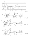
- FIG. 1 illustrates a lane keeping system according to an embodiment of the invention with a schematic representation of a motor vehicle 10 on a two-lane highway 20, 22.
- the lane keeping system comprises an environment sensor system 31 (FIG. 2), which in the exemplary embodiment has a forward and forward facing vehicle body section Sensor 12 and mounted in the rear portion of the vehicle and facing rearward sensor 16 includes.
- the field of view 14 of the front sensor 12 detects the right lane boundary 24 of the right lane 20 and the lane 20 and 22 separating lane marker 26.
- a computing unit of the lane keeping system such as a microprocessor determines the position of the vehicle 10 relative to the lane 20 from the detected sensor data ,
- the field of view 18 of the rear sensor 16 covered the rear of the vehicle 10 to detect vehicles 29 approaching from the rear.
- the environment sensor system 31 outputs a signal to the warning unit 32 for this purpose.
- the warning unit 32 includes a vibration unit 37 that generates a left traveling wave 35 in the steering wheel 33. The driver is thereby caused to counteract by a steering movement to the left of the impending lane crossing.
- the warning unit 32 may, if necessary, also generate a traveling wave 34 running to the right in the steering wheel 33, for example when the vehicle 10 is driving on the left lane 22 of the motorway and threatens to leave the traffic lane 22 there to the left.
- the warning unit 32 also includes a monitoring unit 39 which determines whether a hand rests on the steering wheel 33. If there is no hand on the steering wheel 33, the driver can thus not receive the haptic warning, so an audible warning signal is output via the loudspeaker 36 in a known manner.
- An audible warning may also be issued if the driver does not respond to the haptic warning and continues to threaten or overshoot the lane. Characterized in that in the embodiment, the audible warning is issued only when the haptic warning can not be perceived or was not recorded, interference of the passengers are reduced to an unavoidable for the safety of the vehicle occupant degree.
- the lane keeping system 30 can also be used as an auxiliary device for lane changes, such as when the driver of the vehicle 10 wants to leave the right lane 20 and change to the left lane 22 to overtake a preceding slower vehicle 28. If at the beginning of the steering operation by the rear sensor 16 detected on the lane 22 rapidly approaching from behind vehicle 29, the environment sensor 31 outputs a corresponding signal to the warning unit 32 and the vibration unit 37 generates a traveling right to traveling wave 34 in the steering wheel 33. This will cause the driver to turn right again and cancel the lane change operation. Again, an audible warning is issued when no hand should rest on the steering wheel 33.
- FIG. 3 shows a schematic representation of a lane keeping system 40 according to another embodiment of the invention.
- the environment sensor system 31 outputs a signal to a warning unit 42 in the event of a dangerous overshoot.
- the warning unit 42 causes a vibration mat 47 installed in the driver's seat 43 to generate a vibrating motion 44 or 45 in the direction of required steering correction. This allows the driver to intuitively perform a steering correction in the right direction in response to the vibration movement.
- vibration mat 47 can be generated in this embodiment by the vibration mat 47 and vibration movements from front to back or from back to front to other haptic feedback signals, such as a required braking or acceleration to provide for the driver.
- the environmental sensor system 31 outputs a corresponding signal to a warning unit 52 in the event of a dangerous overshoot.
- the warning unit 52 includes a tilting device 57 that can tilt the driver's seat 53 as a whole slightly to the left or right (reference numeral 54) to indicate to the driver the direction of the required steering correction.
- the environment sensor 31 may include only one sensor 12 in a simpler and less expensive embodiment.
- the function of the lane keeping system as an auxiliary device for lane changes is then not available. Accordingly, the disclosure of the present invention is not intended to be limiting. Instead, the disclosure of the present invention is intended to illustrate the scope of the invention, which is set forth in the following claims.
Abstract
Description
Die Erfindung betrifft ein Spurhaltesystem für ein Kraftfahrzeug mit einer am Kraftfahrzeug angebrachten Umfeldsensoreinrichtung zum Erfassen der Fahrspur des Fahrzeugs, und einer Warneinrichtung zum Warnen des Fahrzeuglenkers im Fall, dass das Fahrzeug die Fahrspur unter Gefahr zu verlassen droht. Die Erfindung betrifft auch ein Verfahren zum Betrieb eines solchen Spurhaltesystems.The invention relates to a lane keeping system for a motor vehicle with an environment-mounted on the motor vehicle sensor device for detecting the lane of the vehicle, and a warning device for warning the driver in the event that the vehicle threatens to leave the lane at risk. The invention also relates to a method for operating such a lane keeping system.
Ein Spurhaltesystem der genannten Art wird beispielsweise bei Fahrten auf der Landstraße eingesetzt. Die Fahrspur, die vor dem Fahrzeug liegt, wird dabei durch eine Umfeldsensorik erfasst. Droht das Fahrzeug, die Fahrspur nach rechts in Richtung des Straßengrabens zu verlassen, so wird eine akustische oder eine haptische Warnung an den Fahrzeuglenker ausgeben. Ein solches System wird insbesondere als so genanntes Einschlafwarnsystem verwendet, das bei fehlenden Lenkreaktionen eines ermüdeten oder abgelenkten Fahrers eine Warnung abgibt.A lane keeping system of the type mentioned is used, for example, when driving on the highway. The lane that lies in front of the vehicle is detected by an environmental sensor. Threatens the vehicle to leave the lane to the right in the direction of the ditch, so will emit an audible or haptic warning to the driver. Such a system is used in particular as a so-called sleep warning system, which gives a warning in the absence of steering reactions of a tired or distracted driver.
Eine andere Einsatzmöglichkeit eines Spurhaltesystems der genannten Art ergibt sich bei der Fahrt auf einer mehrspurigen Autobahn, wenn der Fahrzeuglenker etwa die rechte Spur verlassen und auf die mittlere oder linke Spur wechseln will, um ein vorausfahrendes langsameres Fahrzeug zu überholen. Wird dann beim Beginn des Lenkvorgangs durch die Umfeldsensorik ein sich von hinten schnell näherndes Fahrzeug erkannt, so wird der Fahrzeuglenker durch eine akustische oder haptische Warnung veranlasst, den Spurwechselvorgang abzubrechen.Another possible use of a lane keeping system of the type mentioned results when driving on a multi-lane highway when the driver leaves about the right lane and wants to change to the middle or left lane to overtake a preceding slower vehicle. If, at the beginning of the steering operation, a vehicle rapidly approaching from behind is detected by the environment sensor system, the driver is prompted by an acoustic or haptic warning to stop the lane change process.
Das Spurhaltesystem weist dazu typischerweise eine Sensorelementanordnung auf, die aus einem zweidimensionalen Sensorelementarray oder auch nur einer oder einigen wenigen Sensorelementzeilen besteht. Die Sensorelementanordnung ist in der Regel im Frontbereich des jeweil i-gen Fahrzeugs nach vorne weisend angebracht und tastet einen gewissen Fahrbahnbereich vor dem Fahrzeug ab. Die gewonnenen Bildinformationen werden mit bekannten Techniken analog oder digital weiterverarbeitet, um Informationen über den Verlauf der Fahrbahnmarkierungen oder des Fahrbahnrandes zu extrahieren. Eine Warneinrichtung gibt im Fall, dass das Fahrzeug die momentane Fahrspur unter Gefahr zu verlassen droht, eine akustische oder haptische Warnung aus.The lane keeping system typically has a sensor element arrangement which consists of a two-dimensional sensor element array or only one or a few sensor element rows. As a rule, the sensor element arrangement is mounted in the front region of the respective gen vehicle facing forwardly and scans a certain roadway area in front of the vehicle. The acquired image information is processed analogously or digitally using known techniques in order to extract information about the course of the lane markings or the lane edge. A warning device is in the event that the vehicle threatens to leave the current lane at risk, an audible or haptic warning.
Eine akustische Warnung kann beispielsweise in Form eines so genan n-ten Nagelbandrattergeräusches seitenspezifisch auf derjenigen Fahrzeugseite abgegeben werden, auf der dass Fahrzeug die Fahrspur unter Gefahr zu verlassen droht. Durch ein solches Nagelbandrattergeräusch wird akustisch das Überfahren einer mit Nägeln oder einem Profil versehenen Fahrbahnmarkierung nachgebildet. Als Reaktion auf dieses Geräusch kann der Fahrer intuitiv meist sehr rasch eine geeignete Lenkkorrektur vornehmen. Nachteilig an einer solchen akustischen Warnung ist allerdings, dass die anderen Fahrzeuginsassen dadurch oft stark gestört und verunsichert werden.An acoustic warning can be given page-specific on the side of the vehicle, for example in the form of a so-called nail band rattling noise, on which the vehicle threatens to leave the lane in danger. By such a Nagelbandrattergeräusch acoustically the passing over a nails or a profile provided Track marking simulated. In response to this noise, the driver can intuitively usually make a suitable steering correction very quickly. A disadvantage of such an acoustic warning, however, is that the other vehicle occupants are often greatly disturbed and unsettled.
Eine Störung der anderen Fahrzeuginsassen wird bei einer haptischen Warnung, etwa einer Vibration des Lenkrads zwar vermieden. Allerdings ist eine solche Vibrationswarnung nicht richtungsspezifisch, so dass der Fahrer intuitiv keine gerichtete Lenkkorrektur vornehmen kann. Vielmehr muss der Fahrer, durch die Warnung aufgeschreckt, zunächst die momentane Situation optisch erfassen und dann eine angemessene Reaktion einleiten. Dadurch gehen gerade in kritischen Verkehrssituationen oft wertvolle Sekundenbruchteile verloren.A disturbance of the other vehicle occupants is indeed avoided in a haptic warning, such as a vibration of the steering wheel. However, such a vibration warning is not directional, so that the driver can intuitively make no directional steering correction. Rather, the driver, startled by the warning, first visually capture the current situation and then initiate an appropriate response. As a result, valuable fractions of a second are often lost, especially in critical traffic situations.
Der Erfindung liegt daher die Aufgabe zugrunde, ein Spurhaltesystem der eingangs genannten Art zu schaffen, das bei geringstmöglicher Störung der Mitfahrer dem Fahrzeuglenker dennoch im Gefahrfall eine intuitive Lenkreaktion ermöglicht.The invention is therefore an object of the invention to provide a lane keeping system of the type mentioned, the driver with the least possible disruption of the driver still allows in case of danger an intuitive steering response.
Diese Aufgabe wird durch die im Anspruch 1 angegebenen Merkmale gelöst. Charakteristischerweise ist die Warneinrichtung so ausgelegt und eingerichtet, dass sie dem Fahrzeuglenker eine haptische Richtungsindikation gibt, also eine Information über die Richtung enthält, in der die gefahrvolle Fahrspurüberschreitung droht. Dadurch kann einerseits eine Störung der anderen Fahrzeuginsassen durch akustische Signale vermieden werden, zugleich wird aber die Richtungsinformation in dem Warnsignal erhalten. Der Fahrzeuglenker kann somit, jedenfalls nach einer kurzen Eingewöhnungsphase, intuitiv dem gefahrvollen Spurwechsel gegenlenken.This object is achieved by the features specified in claim 1. Characteristically, the warning device is designed and set up in such a way that it gives the vehicle driver a haptic direction indication, that is, contains information about the direction in which the dangerous lane crossing is imminent. As a result, on the one hand a disturbance of the other vehicle occupants can be avoided by acoustic signals, but at the same time the direction information is obtained in the warning signal. The driver can thus, at least after a short Acclimation phase, intuitively counteract the dangerous lane change.
Vorteilhafte Ausgestaltungen und Weiterbildungen der Erfindung sind in den Unteransprüchen gekennzeichnet.Advantageous embodiments and further developments of the invention are characterized in the subclaims.
Bevorzugt ist nach der Weiterbildung der Erfindung nach Patentanspruch 2 vorgesehen, dass die Warneinrichtung eine mit der Lenkung zusammenwirkende Vibrationseinrichtung aufweist, zum Erzeugen einer haptischen Rückmeldung für den Fahrzeuglenker durch Vibration des Lenkrads.Preferably, according to the embodiment of the invention according to claim 2, that the warning device has a cooperating with the steering vibration device to generate a haptic feedback for the vehicle driver by vibration of the steering wheel.
Dabei ist in vorteilhafter Ausgestaltung der Erfindung nach Patentanspruch 3 vorgesehen, dass die mit der Lenkung zusammenwirkende Vibrationseinrichtung zum Erzeugen einer Wanderwelle auf dem Lenkrad eingerichtet ist, wobei der Verlauf der Wanderwelle die Richtung angibt, in der die gefahrvolle Fahrspurüberschreitung droht. Die Wanderwelle kann beispielsweise von links nach rechts oder von rechts nach links verlaufen, um dem Fahrer die Richtung der erforderlichen Lenkkorrektur anzuzeigen. Der Fahrer spürt über seine aufliegenden Hände die Richtung der Wanderwellen und kann somit direkte Gegenmaßnahmen ergreifen.It is provided in an advantageous embodiment of the invention according to claim 3, that the cooperating with the steering vibration device is adapted to generate a traveling wave on the steering wheel, wherein the course of the traveling wave indicates the direction in which threatens the dangerous lane crossing. The traveling wave may, for example, run from left to right or from right to left to indicate to the driver the direction of the required steering correction. The driver feels the direction of the traveling waves via his resting hands and can therefore take direct countermeasures.
Nach der Maßnahme des Patentanspruchs 4 ist neben der Vibrationsei n-richtung eine Sekundärwarnvorrichtung zur Ausgabe eines optischen und/oder akustischen Warnsignals vorgesehen. Dann kann im Fall, dass die haptische Warnung ignoriert wird oder erfolglos bleibt, ein weiteres anders geartetes Warnsignal abgegeben werden. Störungen der Mitfahrer werden damit auf ein für die Sicherheit der Fahrzeuginsassen unvermeidbares Maß reduziert.After the measure of claim 4, a secondary warning device for outputting an optical and / or acoustic warning signal is provided in addition to the Vibrationsei n-direction. Then, in the event that the haptic warning is ignored or fails, another warning signal may be issued. Disturbances of the passengers are thus reduced to an unavoidable level for the safety of the vehicle occupants.
In der Weiterbildung der Erfindung nach Patentanspruch 5 ist dazu mit Vorteil eine Überwachungseinrichtung vorgesehen, die feststellt, ob der Fahrzeuglenker eine Hand am Lenkrad aufliegen hat, und die, falls keine Hand am Lenkrad aufliegt, die Sekundärwarnvorrichtung auslöst.In the development of the invention according to claim 5, a monitoring device is provided to advantage, which determines whether the driver has a hand on the steering wheel, and, if no hand rests on the steering wheel, the secondary warning device triggers.
Gemäß der ebenfalls bevorzugten Weiterbildung der Erfindung nach Patentanspruch 6 ist vorgesehen, dass die Warneinrichtung eine mit dem Fahrersitz zusammenwirkende Vibrationseinrichtung aufweist, zum Erzeugen einer haptischen Rückmeldung für den Fahrzeuglenker durch Vibration des Fahrersitzes.According to the likewise preferred embodiment of the invention according to claim 6 is provided that the warning device has a cooperating with the driver's seat vibration device for generating a haptic feedback for the vehicle driver by vibration of the driver's seat.
Dabei kann die mit dem Fahrersitz zusammenwirkende Vibrationseinrichtung nach der Maßnahme des Patentanspruchs 7 mit Vorteil durch eine Vibrationsmatte zum Erzeugen von Vibrationen in verschiedenen Richtungen gebildet sein, wobei die Richtung der Vibrationen die Richtung angibt, in der die gefahrvolle Fahrspurüberschreitung droht.The cooperating with the driver's seat vibration device according to the measure of claim 7 can be advantageously formed by a vibration mat for generating vibrations in different directions, the direction of the vibrations indicating the direction in which the dangerous lane violation threatens.
Nach einer weiteren bevorzugten Weiterbildung der Erfindung gemäß Patentanspruch 8 ist vorgesehen, dass die Warneinrichtung eine mit dem Fahrersitz zusammenwirkende Kippvorrichtung aufweist, zum Verkippen des Fahrersitzes in eine Richtung, die die Richtung angibt, in der die gefahrvolle Fahrspurüberschreitung droht. Beispielsweise kann der Fahrersitz durch die Kippvorrichtung als Ganzes leicht nach links oder rechts weggekippt werden, um den Fahrzeuglenker zu einer entsprechenden Lenkkorrektur zu veranlassen.According to a further preferred embodiment of the invention according to claim 8 is provided that the warning device has a cooperating with the driver's seat tilting device for tilting the driver's seat in a direction indicating the direction in which threatens the dangerous lane violation. For example, the driver's seat can be tilted slightly to the left or right by the tilting device as a whole in order to cause the vehicle driver to a corresponding steering correction.
Die Umfeldsensoreinrichtung des Kraftfahrzeugs kann nach der Ausgestaltung des Patentanspruchs 9 mit Vorteil eine mit der Warneinrichtung zusammenwirkende Sensoreinrichtung zum Erfassen von sich rückwärtig nähernden Fahrzeugen aufweisen, zur Ausgabe einer Warnung, falls sich bei einem Wechsel auf eine neue Fahrspur sich auf der neuen Fahrspur von hinten ein Fahrzeug schnell nähert.According to the embodiment of claim 9, the surroundings sensor device of the motor vehicle may advantageously have a sensor device cooperating with the warning device for detecting rear approaching vehicles, for outputting a warning, if present When changing to a new lane, a vehicle quickly approaches from behind on the new lane.
Insbesondere enthält die Umfeldsensoreinrichtung des Kraftfahrzeugs zweckmäßig einen Radarsensor, einen Ultraschallsensor oder eine Bildaufnahmekamera.In particular, the environment sensor device of the motor vehicle expediently contains a radar sensor, an ultrasound sensor or an image recording camera.
Bei einem Verfahren zum Betrieb eines derartigen Spurhaltesystems für ein Kraftfahrzeug wird erfindungsgemäß die Fahrspur des Fahrzeugs erfasst, wird beurteilt, ob das Fahrzeug die Fahrspur unter Gefahr zu verlassen droht und wird ein Warnsignal für den Fahrzeuglenker erzeugt, wenn das Fahrzeug die Fahrspur unter Gefahr zu verlassen droht, wobei charakteristischerweise das Warnsignal dem Fahrzeuglenker eine haptische Rückmeldung gibt, die eine Information über die Richtung enthält, in der die gefahrvolle Fahrspurüberschreitung droht.In a method for operating such a lane keeping system for a motor vehicle according to the invention detects the lane of the vehicle, it is judged whether the vehicle threatens to leave the lane in danger and a warning signal is generated for the driver when the vehicle to leave the lane under danger threatening, wherein characteristically the warning signal gives the driver a haptic feedback, which contains information about the direction in which threatens the dangerous lane crossing.
Ausführungsbeispiele der Erfindung werden nachstehend anhand der Zeichnungen näher erläutert. Es zeigen
- Fig. 1
- eine schematische Darstellung eines Kraftfahrzeugs mit einem Spurhaltesystem nach einem Ausführungsbeispiel der Erfindung auf einer zweispurigen Autobahn;
- Fig. 2
- eine schematische Darstellung eines Spurhaltesystems nach einem Ausführungsbeispiel der Erfindung, bei dem Wanderwellen im Lenkrad die Richtung einer gefahrvollen Fahrspurüberschreitung angeben;
- Fig. 3
- eine schematische Darstellung eines Spurhaltesystems nach einem anderen Ausführungsbeispiel der Erfindung, bei dem Vibrationen des Fahrersitzes die Richtung einer gefahrvollen Fahrspurüberschreitung angeben; und
- Fig. 4
- eine schematische Darstellung eines Spurhaltesystems nach einem weiteren Ausführungsbeispiel der Erfindung, bei dem eine Verkippung des Fahrersitzes die Richtung einer gefahrvollen Fahrspurüberschreitung angibt.
- Fig. 1
- a schematic representation of a motor vehicle with a lane keeping system according to an embodiment of the invention on a two-lane highway;
- Fig. 2
- a schematic representation of a lane keeping system according to an embodiment of the invention, in which traveling waves in the steering wheel indicate the direction of a dangerous lane crossing;
- Fig. 3
- a schematic representation of a lane keeping system according to another embodiment of the invention, wherein the vibrations of the driver's seat indicate the direction of a dangerous lane violation; and
- Fig. 4
- a schematic representation of a lane keeping system according to another embodiment of the invention, in which a tilting of the driver's seat indicates the direction of a dangerous lane violation.
Figur 1 illustriert ein Spurhaltesystem nach einem Ausführungsbeispiel der Erfindung mit einer schematischen Darstellung eines Kraftfahrzeugs 10 auf einer zweispurigen Autobahn 20, 22. Das Spurhaltesystem umfasst eine Umfeldsensorik 31 (Fig. 2), die im Ausführungsbeispiel einen im vorderen Fahrzeugabschnitt angebrachten und nach vorne weisenden vorderen Sensor 12 und einen im hinteren Fahrzeugabschnitt angebrachten und nach hinten weisenden rückwärtigen Sensor 16 enthält.1 illustrates a lane keeping system according to an embodiment of the invention with a schematic representation of a
Das Gesichtsfeld 14 des vorderen Sensors 12 erfasst die rechte Fahrbahnbegrenzung 24 der rechten Fahrspur 20 und die die Fahrspuren 20 und 22 trennende Fahrbahnmarkierung 26. Eine Recheneinheit des Spurhaltesystems, beispielsweise ein Mikroprozessor, bestimmt aus den erfassten Sensordaten die Position des Fahrzeugs 10 relativ zur Fahrspur 20.The field of
Das Gesichtsfeld 18 des hinteren Sensors 16 deckte den rückwärtigen Bereich des Fahrzeugs 10 ab, um von hinten herankommende Fahrzeuge 29 zu erfassen.The field of
Droht das Fahrzeug 10, etwa aufgrund einer Ablenkung oder der Übermüdung des Fahrers, die Fahrbahnbegrenzung 24 zu überschreiten und die Fahrspur 20 nach rechts zu verlassen, so wird im Lenkrad eine Wanderwelle erzeugt, die der Fahrer über seine aufliegende Hände auf die Gefahr hinweist und zu Gegenmaßnahmen veranlasst.Threatens the
Wie die schematische Darstellung des Spurhaltesystems 30 der Fig. 2 illustriert, gibt die Umfeldsensorik 31 dazu ein Signal an die Warneinheit 32 aus. Die Warneinheit 32 enthält eine Vibrationseinheit 37, die eine nach links laufende Wanderwelle 35 in dem Lenkrad 33 erzeugt. Der Fahrer wird dadurch veranlasst, durch eine Lenkbewegung nach links der drohenden Fahrspurüberschreitung entgegenzuwirken. Die Warneinheit 32 kann, falls erforderlich, auch eine nach rechts laufende Wanderwelle 34 im Lenkrad 33 erzeugen, etwa wenn das Fahrzeug 10 auf der linken Spur 22 der Autobahn fährt und dort die Fahrspur 22 nach links zu verlassen droht.As the schematic illustration of the
Die Warneinheit 32 enthält auch eine Überwachungseinheit 39, die feststellt, ob eine Hand am Lenkrad 33 aufliegt. Liegt keine Hand am Lenkrad 33 auf, kann der Fahrer also den haptischen Warnhinweis nicht erhalten, so wird über den Lautsprecher 36 in bekannter Weise ein akustisches Warnsignal ausgegeben.The
Ein akustisches Warnsignal kann auch ausgegeben werden, wenn der Fahrer auf den haptischen Warnhinweis hin nicht reagiert und weiter eine Fahrspurüberschreitung droht oder erfolgt. Dadurch, dass im Ausführungsbeispiel die akustische Warnung nur dann abgegeben wird, wenn der haptische Warnhinweis nicht wahrgenommen werden kann oder nicht aufgenommen wurde, werden Störungen der Mitfahrer auf ein für die Sicherheit der Fahrzeuginsassen unvermeidbares Maß reduziert.An audible warning may also be issued if the driver does not respond to the haptic warning and continues to threaten or overshoot the lane. Characterized in that in the embodiment, the audible warning is issued only when the haptic warning can not be perceived or was not recorded, interference of the passengers are reduced to an unavoidable for the safety of the vehicle occupant degree.
Durch den rückwärtigen Sensor 16 kann das Spurhaltesystem 30 auch als Hilfsvorrichtung für Spurwechsel eingesetzt werden, wenn etwa der Fahrer des Fahrzeugs 10 die rechte Fahrspur 20 verlassen und auf die linke Fahrspur 22 wechseln will, um ein vorausfahrendes langsameres Fahrzeug 28 zu überholen. Wird beim Beginn des Lenkvorgangs durch den rückwärtigen Sensor 16 ein auf der Fahrspur 22 schnell von hinten herankommendes Fahrzeug 29 erfasst, so gibt die Umfeldsensorik 31 ein entsprechendes Signal an die Warneinheit 32 aus und die Vibrationseinheit 37 erzeugt eine nach rechts laufende Wanderwelle 34 in dem Lenkrad 33. Dadurch wird der Fahrer veranlasst, wieder nach rechts zu lenken und den Spurwechselvorgang abzubrechen. Auch hier wird ein akustisches Warnsignal ausgegeben, wenn keine Hand am Lenkrad 33 aufliegen sollte.Through the
Figur 3 zeigt eine schematische Darstellung eines Spurhaltesystems 40 nach einem anderen Ausführungsbeispiel der Erfindung. Bei diesem Ausführungsbeispiel gibt die gibt die Umfeldsensorik 31 bei Drohen einer gefahrvollen Spurüberschreitung ein Signal an eine Warneinheit 42 aus. Die Warneinheit 42 veranlasst eine im Fahrersitz 43 verbaute Vibrationsmatte 47, eine Vibrationsbewegung 44 oder 45 in der Richtung der erforderlichen Lenkkorrektur zu erzeugen. Dadurch kann der Fahrer als Reaktion auf die Vibrationsbewegung intuitiv eine Lenkkorrektur in die richtige Richtung durchführen.Figure 3 shows a schematic representation of a
Neben den genannten nach rechts bzw. nach links laufenden Vibrationsbewegungen 44 bzw. 45 können bei dieser Ausführungsform durch die Vibrationsmatte 47 auch Vibrationsbewegungen von vorne nach hinten oder von hinten nach vorne erzeugt werden, um andere haptische Rückmeldungssignale, etwa für einen erforderlichen Brems- oder Beschleunigungsvorgang für den Fahrer bereitzustellen.In addition to the mentioned to the right or to the left
Auch bei dem in Figur 4 gezeigten Ausführungsbeispiel eines Spurhaltesystems 50 gibt die Umfeldsensorik 31 bei Drohen einer gefahrvollen Spurüberschreitung ein entsprechendes Signal an eine Warneinheit 52 aus. Die Warneinheit 52 enthält eine Kippvorrichtung 57, die den Fahrersitz 53 als Ganzes leicht nach links oder rechts kippen kann (Bezugszeichen 54), um dem Fahrer die Richtung der erforderlichen Lenkkorrektur anzuzeigen.Even in the exemplary embodiment of a lane-keeping
Während die Erfindung insbesondere mit Bezug auf bevorzugte Ausführungsbeispiele gezeigt und beschrieben worden ist, versteht sich für den Fachmann, dass Änderungen in Gestalt und Einzelheiten gemacht werden können, ohne von dem Gedanken und Umfang der Erfindung abzuweichen. Beispielsweise kann die Umfeldsensorik 31 in einer einfacheren und preiswerteren Ausgestaltung nur einen Sensor 12 enthalten. Die Funktion des Spurhaltesystems als Hilfsvorrichtung für Spurwechsel steht dann nicht zur Verfügung. Dementsprechend soll die Offenbarung der vorliegenden Erfindung nicht einschränkend sein. Statt dessen soll die Offenbarung der vorliegenden Erfindung den Umfang der Erfindung veranschaulichen, der in den nachfolgenden Ansprüchen dargelegt ist.While the invention has been particularly shown and described with reference to preferred embodiments, it will be understood by those skilled in the art that changes in form and detail may be made without departing from the spirit and scope of the invention. For example, the
Claims (10)
die Warneinrichtung (32; 42; 52) ausgelegt und eingerichtet ist, dem Fahr-zeuglenker eine haptische Rückmeldung zu geben, die eine Information über die Richtung enthält, in der die gefahrvolle Fahrspurüberschreitung droht.Lane keeping system for a motor vehicle with
the warning device (32; 42; 52) is designed and set up to give the driver a haptic feedback which contains information about the direction in which the hazardous lane violation is imminent.
die Warneinrichtung (32) eine mit der Lenkung zusammenwirkende Vibrationseinrichtung (37) aufweist, zum Erzeugen einer haptischen Rückmeldung für den Fahrzeuglenker durch Vibration des Lenkrads (33).Lane keeping system according to claim 1, characterized in that
the warning device (32) has a vibration device (37) cooperating with the steering, for generating a haptic feedback for the vehicle driver by vibration of the steering wheel (33).
die mit der Lenkung zusammenwirkende Vibrationseinrichtung (37) zum Erzeugen einer Wanderwelle (34, 35) auf dem Lenkrad (33) eingerichtet ist, wobei der Verlauf der Wanderwelle (34, 35) die Richtung angibt, in der die gefahrvolle Fahrspurüberschreitung droht.Lane keeping system according to claim 2, characterized in that
the steering means cooperating with vibration device (37) for generating a traveling wave (34, 35) is arranged on the steering wheel (33), wherein the course of the traveling wave (34, 35) indicates the direction in which the dangerous lane crossing threatens.
neben der Vibrationseinrichtung (37) eine Sekundärwarnvorrichtung (36) zur Ausgabe eines optischen und/oder akustischen Warnsignals vorgesehen ist.Lane keeping system according to claim 2 or 3, characterized in that
a secondary warning device (36) for outputting an optical and / or acoustic warning signal is provided in addition to the vibration device (37).
eine Überwachungseinrichtung (39) vorgesehen ist, die feststellt, ob der Fahrzeuglenker eine Hand am Lenkrad (33) aufliegen hat, und die, im Fall, dass keine Hand am Lenkrad (33) aufliegt, die Sekundärwarnvorrichtung (36) auslöst.Lane keeping system according to claim 4, characterized in that
a monitoring device (39) is provided, which determines whether the driver has a hand on the steering wheel (33) and which, in the event that no hand on the steering wheel (33) rests, the secondary warning device (36) triggers.
die Warneinrichtung (42) eine mit dem Fahrersitz (43) zusammenwirkende Vibrationseinrichtung (47) aufweist, zum Erzeugen einer haptischen Rückmeldung für den Fahrzeuglenker durch Vibration des Fahrersitzes (43).Lane keeping system according to claim 1, characterized in that
the warning device (42) has a vibration device (47) cooperating with the driver's seat (43) for generating a haptic feedback for the vehicle driver by vibration of the driver's seat (43).
die mit dem Fahrersitz (43) zusammenwirkende Vibrationseinrichtung durch eine Vibrationsmatte (47) zum Erzeugen von Vibrationen in verschiedenen Richtungen (44, 45) gebildet ist, wobei die Richtung der Vi b-rationen die Richtung angibt, in der die gefahrvolle Fahrspurüberschreitung droht.Lane keeping system according to claim 6, characterized in that
the vibration device cooperating with the driver's seat (43) is formed by a vibration mat (47) for generating vibrations in different directions (44, 45), the direction of the vibrations indicating the direction in which the dangerous lane departure is imminent.
die Warneinrichtung (52) eine mit dem Fahrersitz (53) zusammenwirkende Kippvorrichtung (57) aufweist, zum Verkippen des Fahrersitzes (53) in eine Richtung, die die Richtung angibt, in der die gefahrvolle Fahrspurüberschreitung droht.Lane keeping system according to claim 1, characterized in that
the warning device (52) has a tilting device (57) cooperating with the driver's seat (53) for tilting the driver's seat (53) into one Direction indicating the direction in which the dangerous lane crossing threatens.
dadurch gekennzeichnet, dass
die Umfeldsensoreinrichtung (31) des Kraftfahrzeugs (10) eine mit der Warneinrichtung zusammenwirkende Sensoreinrichtung (16) zum Erfassen von sich rückwärtig nähernden Fahrzeugen aufweist, zur Ausgabe einer Warnung, falls sich bei einem Wechsel auf eine neue Fahrspur (22) auf der neuen Fahrspur (22) von hinten ein Fahrzeug (29) schnell nähert.Lane keeping system according to one of the preceding claims,
characterized in that
the surroundings sensor device (31) of the motor vehicle (10) has a sensor device (16) cooperating with the warning device for detecting rear approaching vehicles, for outputting a warning if, when changing to a new traffic lane (22) on the new traffic lane (16) 22) quickly approaches a vehicle (29) from behind.
dadurch gekennzeichnet, dass
characterized in that
Applications Claiming Priority (2)
| Application Number | Priority Date | Filing Date | Title |
|---|---|---|---|
| DE10249354 | 2002-10-23 | ||
| DE10249354A DE10249354A1 (en) | 2002-10-23 | 2002-10-23 | Lane keeping system for a motor vehicle and operating method |
Publications (2)
| Publication Number | Publication Date |
|---|---|
| EP1413500A1 true EP1413500A1 (en) | 2004-04-28 |
| EP1413500B1 EP1413500B1 (en) | 2007-01-24 |
Family
ID=32049562
Family Applications (1)
| Application Number | Title | Priority Date | Filing Date |
|---|---|---|---|
| EP03102589A Expired - Lifetime EP1413500B1 (en) | 2002-10-23 | 2003-08-19 | Lane keeping system for a vehicle and method of operation |
Country Status (2)
| Country | Link |
|---|---|
| EP (1) | EP1413500B1 (en) |
| DE (2) | DE10249354A1 (en) |
Cited By (9)
| Publication number | Priority date | Publication date | Assignee | Title |
|---|---|---|---|---|
| EP1584901A1 (en) * | 2004-04-08 | 2005-10-12 | Wolfgang Dr. Sassin | Apparatus for the dynamic optical, acoustical or tactile representation of the sourrounding of a vehicle |
| WO2005118372A1 (en) * | 2004-06-02 | 2005-12-15 | Daimlerchrysler Ag | Method for holding the course of a vehicle |
| EP1661751A1 (en) * | 2004-11-26 | 2006-05-31 | Nissan Motor Co., Ltd. | Driving intention estimating system, driver assisting system, and vehicle with the system |
| WO2006081936A1 (en) * | 2005-02-02 | 2006-08-10 | Daimlerchrysler Ag | Method and device for carrying out an automatic steering intervention in particular for lane-keeping assistance |
| WO2007020153A1 (en) * | 2005-08-18 | 2007-02-22 | Robert Bosch Gmbh | Method for the detection of a traffic zone |
| DE102008018512A1 (en) | 2008-04-12 | 2009-10-15 | Fendt, Günter | Method for preventive protection of vehicle occupants in dangerous situations, involves determining value of distance of vehicle to objects on edge of road or distance of vehicle to lateral road marking or lateral road limit |
| DE102012200248A1 (en) * | 2012-01-10 | 2013-07-11 | Bayerische Motoren Werke Aktiengesellschaft | Warning apparatus for warning vehicle driver, has vibration generator that is provided with sealed vibration motors for producing vibration signals simultaneously in response to trigger signal of driver assistance system |
| US10377307B2 (en) | 2016-01-18 | 2019-08-13 | Toyota Motor Engineering & Manufacturing North America, Inc. | Vehicle proximity condition detection and haptic notification system |
| US11238671B2 (en) | 2019-04-18 | 2022-02-01 | Honda Motor Co., Ltd. | System and method for providing haptic alerts within a vehicle |
Families Citing this family (11)
| Publication number | Priority date | Publication date | Assignee | Title |
|---|---|---|---|---|
| DE10303870B4 (en) * | 2003-01-31 | 2014-12-31 | Bayerische Motoren Werke Aktiengesellschaft | Motor vehicle with a driver assistance system with tracking |
| DE102004047545A1 (en) * | 2004-09-30 | 2006-04-06 | Daimlerchrysler Ag | Haptic driver response generating method for vehicle, involves activating acknowledgement device and generating excitation parameters with sinusoidal temporal characteristics for generating haptic driver response |
| DE102005037273A1 (en) | 2005-08-08 | 2007-02-15 | Robert Bosch Gmbh | Lane assistance system for vehicles |
| DE102007015432B4 (en) * | 2007-03-30 | 2017-03-23 | Bayerische Motoren Werke Aktiengesellschaft | Haptic display unit in a motor vehicle |
| DE102007035504A1 (en) * | 2007-07-28 | 2009-01-29 | Bayerische Motoren Werke Aktiengesellschaft | Motor vehicle comprises lane detection system for determining lane parameter related to motor vehicle and lane driven through by motor vehicle, where support system control device is equipped |
| DE102009045937A1 (en) | 2008-10-22 | 2010-04-29 | Continental Teves Ag & Co. Ohg | Motor vehicle's lane holding method, involves detecting optimized lane in real time by forecasting driving path of individual and adjacent vehicles and detecting environment situation, and evaluating positions of adjacent vehicles |
| DE102011056042A1 (en) | 2011-12-05 | 2013-06-06 | Zf Lenksysteme Gmbh | Haptic feedback system for motor car, has electric motor, worm gear, and threaded spindle producing oscillations in steering wheel by repeated exchanging of rotational direction of motor, and introducing oscillations into steering column |
| DE102011122566A1 (en) | 2011-12-10 | 2013-06-13 | Volkswagen Aktiengesellschaft | Warning device for motor vehicle, has computing device for activating warning of driver when driver does not steers vehicle over time period, where device executes time warning escalation to perform multi-stage warnings within minute |
| FR3015414B1 (en) * | 2013-12-19 | 2016-01-08 | Renault Sas | DRIVER WARNING SYSTEM FOR MOTOR VEHICLE AND ASSOCIATED METHOD |
| DE102016216590A1 (en) | 2016-09-01 | 2018-03-01 | Bayerische Motoren Werke Aktiengesellschaft | Method, device and computer program for generating and transmitting driver information |
| DE102017202468B4 (en) | 2017-02-15 | 2018-09-20 | Bayerische Motoren Werke Aktiengesellschaft | Warning device of a vehicle for warning a vehicle driver when leaving a lane |
Citations (5)
| Publication number | Priority date | Publication date | Assignee | Title |
|---|---|---|---|---|
| EP0640903A1 (en) * | 1993-08-28 | 1995-03-01 | Lucas Industries Public Limited Company | A driver assistance system for a vehicle |
| DE19602766A1 (en) * | 1995-01-27 | 1996-08-08 | Fuji Heavy Ind Ltd | Motor vehicle anti-collision and inadvertent driving line change warning device |
| US5699057A (en) * | 1995-06-16 | 1997-12-16 | Fuji Jukogyo Kabushiki Kaisha | Warning system for vehicle |
| DE19818259A1 (en) * | 1997-05-03 | 1998-11-05 | Volkswagen Ag | Monitoring travel of motor vehicle in steps |
| DE10027922A1 (en) * | 2000-06-06 | 2002-01-24 | Bosch Gmbh Robert | Method for detecting the position of hands on a steering wheel |
-
2002
- 2002-10-23 DE DE10249354A patent/DE10249354A1/en not_active Withdrawn
-
2003
- 2003-08-19 DE DE50306361T patent/DE50306361D1/en not_active Expired - Lifetime
- 2003-08-19 EP EP03102589A patent/EP1413500B1/en not_active Expired - Lifetime
Patent Citations (5)
| Publication number | Priority date | Publication date | Assignee | Title |
|---|---|---|---|---|
| EP0640903A1 (en) * | 1993-08-28 | 1995-03-01 | Lucas Industries Public Limited Company | A driver assistance system for a vehicle |
| DE19602766A1 (en) * | 1995-01-27 | 1996-08-08 | Fuji Heavy Ind Ltd | Motor vehicle anti-collision and inadvertent driving line change warning device |
| US5699057A (en) * | 1995-06-16 | 1997-12-16 | Fuji Jukogyo Kabushiki Kaisha | Warning system for vehicle |
| DE19818259A1 (en) * | 1997-05-03 | 1998-11-05 | Volkswagen Ag | Monitoring travel of motor vehicle in steps |
| DE10027922A1 (en) * | 2000-06-06 | 2002-01-24 | Bosch Gmbh Robert | Method for detecting the position of hands on a steering wheel |
Cited By (13)
| Publication number | Priority date | Publication date | Assignee | Title |
|---|---|---|---|---|
| EP1584901A1 (en) * | 2004-04-08 | 2005-10-12 | Wolfgang Dr. Sassin | Apparatus for the dynamic optical, acoustical or tactile representation of the sourrounding of a vehicle |
| WO2005118372A1 (en) * | 2004-06-02 | 2005-12-15 | Daimlerchrysler Ag | Method for holding the course of a vehicle |
| US7809506B2 (en) | 2004-11-26 | 2010-10-05 | Nissan Motor Co., Ltd. | Driving intention estimation system, driver assisting system, and vehicle with the system |
| EP1661751A1 (en) * | 2004-11-26 | 2006-05-31 | Nissan Motor Co., Ltd. | Driving intention estimating system, driver assisting system, and vehicle with the system |
| WO2006081936A1 (en) * | 2005-02-02 | 2006-08-10 | Daimlerchrysler Ag | Method and device for carrying out an automatic steering intervention in particular for lane-keeping assistance |
| WO2007020153A1 (en) * | 2005-08-18 | 2007-02-22 | Robert Bosch Gmbh | Method for the detection of a traffic zone |
| US8818694B2 (en) | 2005-08-18 | 2014-08-26 | Robert Bosch Gmbh | Method for detecting a traffic zone |
| DE102008018512A1 (en) | 2008-04-12 | 2009-10-15 | Fendt, Günter | Method for preventive protection of vehicle occupants in dangerous situations, involves determining value of distance of vehicle to objects on edge of road or distance of vehicle to lateral road marking or lateral road limit |
| DE102008018512B4 (en) * | 2008-04-12 | 2012-12-13 | Günter Fendt | Driver assistance system and associated procedure |
| DE102012200248A1 (en) * | 2012-01-10 | 2013-07-11 | Bayerische Motoren Werke Aktiengesellschaft | Warning apparatus for warning vehicle driver, has vibration generator that is provided with sealed vibration motors for producing vibration signals simultaneously in response to trigger signal of driver assistance system |
| DE102012200248B4 (en) * | 2012-01-10 | 2021-02-18 | Bayerische Motoren Werke Aktiengesellschaft | Warning device in a motor vehicle for warning a vehicle driver |
| US10377307B2 (en) | 2016-01-18 | 2019-08-13 | Toyota Motor Engineering & Manufacturing North America, Inc. | Vehicle proximity condition detection and haptic notification system |
| US11238671B2 (en) | 2019-04-18 | 2022-02-01 | Honda Motor Co., Ltd. | System and method for providing haptic alerts within a vehicle |
Also Published As
| Publication number | Publication date |
|---|---|
| EP1413500B1 (en) | 2007-01-24 |
| DE50306361D1 (en) | 2007-03-15 |
| DE10249354A1 (en) | 2004-05-06 |
Similar Documents
| Publication | Publication Date | Title |
|---|---|---|
| EP1682381B1 (en) | Lane guidance system for a motor vehicle and operating method | |
| EP1413500B1 (en) | Lane keeping system for a vehicle and method of operation | |
| DE102014002116B4 (en) | Method for operating a driver assistance system for overtaking operations and motor vehicle | |
| EP1537441B1 (en) | Driver assistance system for a road vehicle | |
| DE102009041187A1 (en) | Method and device for adaptation of parameters of a driver assistance system | |
| WO2005118372A1 (en) | Method for holding the course of a vehicle | |
| DE102005052032A1 (en) | Motor vehicle`s longitudinal speed influencing device, has sensor device measuring distance of vehicle, and activation device detecting predefined driving condition and automatically activating computer unit during detection of condition | |
| DE102019006685B4 (en) | Method for operating a vehicle | |
| DE10220782A1 (en) | Motor vehicle emergency system for detecting when the driver is unfit to drive, triggers an emergency response that is matched to surrounding traffic conditions by use of the instrumentation of the driver assistance system | |
| DE102010035718B4 (en) | Method for operating a driver assistance system and motor vehicle | |
| DE102018207675A1 (en) | Method for switching between different automation levels of a vehicle | |
| DE102005009701B4 (en) | Replica of acoustic track markings | |
| DE102008021068B4 (en) | Hazard warning device for a motor vehicle and driver assistance system | |
| DE10352955A1 (en) | Driver assistance system to assist the tracking of a motor vehicle and apparatus for operating the driver assistance system | |
| DE102014201037A1 (en) | Transmission of information through surface modification | |
| DE19843367A1 (en) | Shunting aid system, esp. for parking vehicles, outputs distance warning signal if set of trigger conditions is fulfilled, including that distance to obstruction is less than defined minimum | |
| DE102018212266A1 (en) | Adaptation of an evaluable scanning range of sensors and adapted evaluation of sensor data | |
| DE102009023444A1 (en) | Method for assistance of driver of vehicle in changing traffic lane from momentary traffic lane to adjacent target traffic lane, involves detecting traffic situation in rear and front area of vehicle for adjacent traffic lane by detectors | |
| EP1359486B1 (en) | Information system and method for outputting information by means of a steering wheel | |
| DE102017202615A1 (en) | Lane departure warning method for a driver of a vehicle | |
| DE102004024692A1 (en) | Motor vehicle driver assistance method for keeping to lane, by automatically generating steering wheel torque when lane is left and determining steering wheel angle variation | |
| DE102019103627A1 (en) | Driver assistance system and motor vehicle with such a driver assistance system | |
| DE102010015538A1 (en) | Method for increasing working reliability of car, involves monitoring track of vehicle by recognition unit, and track retaining system activated if critical situation is determined, where vehicle threatens to go from lane in situation | |
| DE102020106850A1 (en) | Method for assisting an occupant when getting out of a vehicle by adapting a display, driver assistance system and vehicle | |
| DE102009007431A1 (en) | Driver assisting method for motor vehicle, involves disabling setting of indicator, if driver deactivates automatic setting of indicator or if operating element of vehicle for manual setting of indicator is quickly actuated by driver |
Legal Events
| Date | Code | Title | Description |
|---|---|---|---|
| PUAI | Public reference made under article 153(3) epc to a published international application that has entered the european phase |
Free format text: ORIGINAL CODE: 0009012 |
|
| AK | Designated contracting states |
Kind code of ref document: A1 Designated state(s): AT BE BG CH CY CZ DE DK EE ES FI FR GB GR HU IE IT LI LU MC NL PT RO SE SI SK TR |
|
| AX | Request for extension of the european patent |
Extension state: AL LT LV MK |
|
| 17P | Request for examination filed |
Effective date: 20041028 |
|
| AKX | Designation fees paid |
Designated state(s): DE FR GB SE |
|
| 17Q | First examination report despatched |
Effective date: 20050124 |
|
| GRAP | Despatch of communication of intention to grant a patent |
Free format text: ORIGINAL CODE: EPIDOSNIGR1 |
|
| GRAS | Grant fee paid |
Free format text: ORIGINAL CODE: EPIDOSNIGR3 |
|
| GRAA | (expected) grant |
Free format text: ORIGINAL CODE: 0009210 |
|
| AK | Designated contracting states |
Kind code of ref document: B1 Designated state(s): DE FR GB SE |
|
| REG | Reference to a national code |
Ref country code: GB Ref legal event code: FG4D Free format text: NOT ENGLISH |
|
| REF | Corresponds to: |
Ref document number: 50306361 Country of ref document: DE Date of ref document: 20070315 Kind code of ref document: P |
|
| REG | Reference to a national code |
Ref country code: SE Ref legal event code: TRGR |
|
| GBT | Gb: translation of ep patent filed (gb section 77(6)(a)/1977) |
Effective date: 20070426 |
|
| ET | Fr: translation filed | ||
| PLBE | No opposition filed within time limit |
Free format text: ORIGINAL CODE: 0009261 |
|
| STAA | Information on the status of an ep patent application or granted ep patent |
Free format text: STATUS: NO OPPOSITION FILED WITHIN TIME LIMIT |
|
| 26N | No opposition filed |
Effective date: 20071025 |
|
| REG | Reference to a national code |
Ref country code: FR Ref legal event code: PLFP Year of fee payment: 14 |
|
| REG | Reference to a national code |
Ref country code: FR Ref legal event code: PLFP Year of fee payment: 15 |
|
| REG | Reference to a national code |
Ref country code: FR Ref legal event code: PLFP Year of fee payment: 16 |
|
| PGFP | Annual fee paid to national office [announced via postgrant information from national office to epo] |
Ref country code: SE Payment date: 20190826 Year of fee payment: 17 |
|
| REG | Reference to a national code |
Ref country code: SE Ref legal event code: EUG |
|
| PG25 | Lapsed in a contracting state [announced via postgrant information from national office to epo] |
Ref country code: SE Free format text: LAPSE BECAUSE OF NON-PAYMENT OF DUE FEES Effective date: 20200820 |
|
| PGFP | Annual fee paid to national office [announced via postgrant information from national office to epo] |
Ref country code: GB Payment date: 20220824 Year of fee payment: 20 |
|
| PGFP | Annual fee paid to national office [announced via postgrant information from national office to epo] |
Ref country code: FR Payment date: 20220822 Year of fee payment: 20 |
|
| PGFP | Annual fee paid to national office [announced via postgrant information from national office to epo] |
Ref country code: DE Payment date: 20221025 Year of fee payment: 20 |
|
| REG | Reference to a national code |
Ref country code: DE Ref legal event code: R084 Ref document number: 50306361 Country of ref document: DE |
|
| REG | Reference to a national code |
Ref country code: DE Ref legal event code: R071 Ref document number: 50306361 Country of ref document: DE |
|
| REG | Reference to a national code |
Ref country code: GB Ref legal event code: PE20 Expiry date: 20230818 |
|
| PG25 | Lapsed in a contracting state [announced via postgrant information from national office to epo] |
Ref country code: GB Free format text: LAPSE BECAUSE OF EXPIRATION OF PROTECTION Effective date: 20230818 |