EP1363340A2 - Cordless power tool system - Google Patents
Cordless power tool system Download PDFInfo
- Publication number
- EP1363340A2 EP1363340A2 EP03017178A EP03017178A EP1363340A2 EP 1363340 A2 EP1363340 A2 EP 1363340A2 EP 03017178 A EP03017178 A EP 03017178A EP 03017178 A EP03017178 A EP 03017178A EP 1363340 A2 EP1363340 A2 EP 1363340A2
- Authority
- EP
- European Patent Office
- Prior art keywords
- battery pack
- power tool
- cordless power
- housing
- terminal block
- Prior art date
- Legal status (The legal status is an assumption and is not a legal conclusion. Google has not performed a legal analysis and makes no representation as to the accuracy of the status listed.)
- Granted
Links
Images


Classifications
-
- B—PERFORMING OPERATIONS; TRANSPORTING
- B25—HAND TOOLS; PORTABLE POWER-DRIVEN TOOLS; MANIPULATORS
- B25F—COMBINATION OR MULTI-PURPOSE TOOLS NOT OTHERWISE PROVIDED FOR; DETAILS OR COMPONENTS OF PORTABLE POWER-DRIVEN TOOLS NOT PARTICULARLY RELATED TO THE OPERATIONS PERFORMED AND NOT OTHERWISE PROVIDED FOR
- B25F5/00—Details or components of portable power-driven tools not particularly related to the operations performed and not otherwise provided for
- B25F5/02—Construction of casings, bodies or handles
-
- H—ELECTRICITY
- H01—ELECTRIC ELEMENTS
- H01M—PROCESSES OR MEANS, e.g. BATTERIES, FOR THE DIRECT CONVERSION OF CHEMICAL ENERGY INTO ELECTRICAL ENERGY
- H01M50/00—Constructional details or processes of manufacture of the non-active parts of electrochemical cells other than fuel cells, e.g. hybrid cells
- H01M50/20—Mountings; Secondary casings or frames; Racks, modules or packs; Suspension devices; Shock absorbers; Transport or carrying devices; Holders
- H01M50/202—Casings or frames around the primary casing of a single cell or a single battery
-
- H—ELECTRICITY
- H01—ELECTRIC ELEMENTS
- H01M—PROCESSES OR MEANS, e.g. BATTERIES, FOR THE DIRECT CONVERSION OF CHEMICAL ENERGY INTO ELECTRICAL ENERGY
- H01M50/00—Constructional details or processes of manufacture of the non-active parts of electrochemical cells other than fuel cells, e.g. hybrid cells
- H01M50/20—Mountings; Secondary casings or frames; Racks, modules or packs; Suspension devices; Shock absorbers; Transport or carrying devices; Holders
- H01M50/204—Racks, modules or packs for multiple batteries or multiple cells
- H01M50/207—Racks, modules or packs for multiple batteries or multiple cells characterised by their shape
- H01M50/213—Racks, modules or packs for multiple batteries or multiple cells characterised by their shape adapted for cells having curved cross-section, e.g. round or elliptic
-
- H—ELECTRICITY
- H01—ELECTRIC ELEMENTS
- H01M—PROCESSES OR MEANS, e.g. BATTERIES, FOR THE DIRECT CONVERSION OF CHEMICAL ENERGY INTO ELECTRICAL ENERGY
- H01M50/00—Constructional details or processes of manufacture of the non-active parts of electrochemical cells other than fuel cells, e.g. hybrid cells
- H01M50/20—Mountings; Secondary casings or frames; Racks, modules or packs; Suspension devices; Shock absorbers; Transport or carrying devices; Holders
- H01M50/247—Mountings; Secondary casings or frames; Racks, modules or packs; Suspension devices; Shock absorbers; Transport or carrying devices; Holders specially adapted for portable devices, e.g. mobile phones, computers, hand tools or pacemakers
-
- H—ELECTRICITY
- H01—ELECTRIC ELEMENTS
- H01M—PROCESSES OR MEANS, e.g. BATTERIES, FOR THE DIRECT CONVERSION OF CHEMICAL ENERGY INTO ELECTRICAL ENERGY
- H01M50/00—Constructional details or processes of manufacture of the non-active parts of electrochemical cells other than fuel cells, e.g. hybrid cells
- H01M50/20—Mountings; Secondary casings or frames; Racks, modules or packs; Suspension devices; Shock absorbers; Transport or carrying devices; Holders
- H01M50/296—Mountings; Secondary casings or frames; Racks, modules or packs; Suspension devices; Shock absorbers; Transport or carrying devices; Holders characterised by terminals of battery packs
-
- H—ELECTRICITY
- H02—GENERATION; CONVERSION OR DISTRIBUTION OF ELECTRIC POWER
- H02J—CIRCUIT ARRANGEMENTS OR SYSTEMS FOR SUPPLYING OR DISTRIBUTING ELECTRIC POWER; SYSTEMS FOR STORING ELECTRIC ENERGY
- H02J7/00—Circuit arrangements for charging or depolarising batteries or for supplying loads from batteries
- H02J7/0042—Circuit arrangements for charging or depolarising batteries or for supplying loads from batteries characterised by the mechanical construction
- H02J7/0045—Circuit arrangements for charging or depolarising batteries or for supplying loads from batteries characterised by the mechanical construction concerning the insertion or the connection of the batteries
-
- Y—GENERAL TAGGING OF NEW TECHNOLOGICAL DEVELOPMENTS; GENERAL TAGGING OF CROSS-SECTIONAL TECHNOLOGIES SPANNING OVER SEVERAL SECTIONS OF THE IPC; TECHNICAL SUBJECTS COVERED BY FORMER USPC CROSS-REFERENCE ART COLLECTIONS [XRACs] AND DIGESTS
- Y02—TECHNOLOGIES OR APPLICATIONS FOR MITIGATION OR ADAPTATION AGAINST CLIMATE CHANGE
- Y02E—REDUCTION OF GREENHOUSE GAS [GHG] EMISSIONS, RELATED TO ENERGY GENERATION, TRANSMISSION OR DISTRIBUTION
- Y02E60/00—Enabling technologies; Technologies with a potential or indirect contribution to GHG emissions mitigation
- Y02E60/10—Energy storage using batteries
Definitions
- the present invention generally pertains to power tools. More particular, the present invention pertains to a system of cordless power tools. More specifically, but without restriction to the particular embodiment and/or use which is shown and described for purposes of illustration, the present invention relates to a system of cordless power tools with an improved battery pack interface. The present invention also pertains to a related method.
- Cordless power tools including interchangeable battery units are widely known in the prior art.
- one such system is shown and described in commonly assigned U.S. Patent No. 3,952,239.
- United States Patent No. 3,952,239 discloses a system of tools utilizing individual tool heads, each of which incorporates its own essential elements such as a motor and a blade or chuck. This type of system reduces space requirements for tool storage and increases the life span for each motor.
- Another significant aspect of systems such as that disclosed by U.S. Patent No. 3,952,239 is the fact that they permit improved utilization of incorporated nickel-cadmium batteries and an associated battery charger which are particularly high cost elements of the system.
- a battery pack for a cordless power tool having a tool housing, the battery pack characterized by:
- a cordless power tool system characterized by:
- a method of releasable and electrically interconnecting a battery pack with a tool terminal block of a cordless power tool having a housing defining a pair of tool grooves, the tool terminal block including a pair of female terminals and a pair of laterally spaced battery pack guide rails, the method characterized by the steps of:
- a system of cordless power tools is characterized by a battery pack and battery charger.
- the battery pack has a housing and a terminal block.
- the housing defines a chamber having a floor.
- the terminal block is disposed in said chamber, said terminal block including a plurality of blade terminals.
- Each blade terminal of said plurality of blade terminals is spaced from said floor.
- the charger includes a plurality of female terminals for receiving said plurality of blade terminals.
- the battery charger further includes a plurality of insulating portions substantially concealing said female terminals.
- the insulating portions each defines an opening for receiving one of said blade terminals thereby providing access to an associated female terminal.
- Each insulating portion includes a horizontally oriented upper portion adapted to be received between an associated blade terminal and said floor.
- a system of cordless power tools is characterized by a rechargeable battery pack and a battery charger.
- the battery pack includes a pair of laterally spaced guide rails and a battery pack terminal block disposed between said guide rails.
- the housing includes an open deck portion for vertically receiving said battery pack and a coupling portion for mechanically engaging said battery pack.
- the coupling portion defines a pair of laterally spaced grooves for receiving said pair of laterally spaced guide rails such that longitudinal translation of said battery pack toward said coupling portion prevents vertical displacement of said battery pack relative to said housing.
- a battery pack for a cordless power tool is characterized by a battery pack housing including first and second laterally spaced sides and a rear side oriented substantially perpendicular to said first and second laterally spaced sides.
- First and second protrusions are disposed adjacent said rear side on said first and second laterally spaced sides, respectively, and are both generally convexly curved. The protrusions facilitate manual extraction of the battery pack from the cordless power tool.
- a method for charging a battery pack for a cordless power tool.
- the battery pack includes positive and negative blade terminals disposed between laterally spaced apart guide rails.
- the method comprises the steps providing a battery charger having a housing and positive and negative female terminals recessed within said housing.
- the housing further has an open deck and a coupling portion having a pair of laterally spaced grooves.
- the open deck is vertically engaged with the battery pack.
- the battery pack is translated horizontally toward said coupling portion.
- the positive and negative female terminals are electrically coupled with the positive and negative male terminals, respectively.
- the battery pack and said charger are mechanically coupled by slidably engaging the guide rails with said grooves such that vertical displacement of the battery pack relative to said charger is prevented.
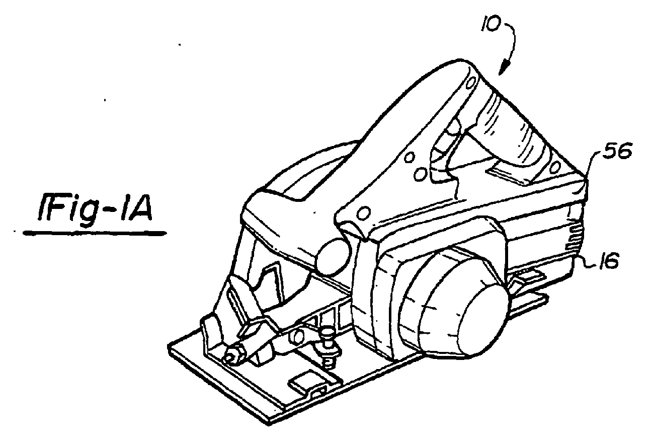
- Figures 1A-1C are illustrations of a first cordless power tool of a cordless power tool system constructed in accordance with the teachings of a first preferred embodiment of the present invention.
- a system of cordless power tools constructed in accordance with the teachings of a preferred embodiment of the present invention is illustrated.
- Exemplary cordless power tools of the system are shown to include, by way of examples, a circular power saw 10 (Figure 1), a reciprocating saw 12 (Figure 13), and a drill 14 ( Figure 15).
- the tools 10-14 each include a conventional DC motor (not shown) adapted to be powered with a common voltage.
- the tools 10-14 are intended to be driven by 24 volt electricity. It will become evident to those skilled that the present invention is not limited to the particular types of tools shown in the drawings nor to specific voltages. In this regard, the teachings of the present invention are applicable to virtually any type of power tool and any supply voltage.
- the system of the present invention is additionally shown to generally include a first rechargeable battery pack 16.
- the system of the present invention is further shown to generally include an AC/DC converter 18 and a battery charger 20 for charging the battery pack 16.
- the battery charger 20 is shown in Figure 11 partially cut-away and operatively associated with the battery pack 16.
- the AC/DC converter is shown in Figure 13 removably attached to the reciprocating saw 12.
- the focus of the present invention most particularly pertains to the interfaces between the tools 10-14 and the battery pack 16, the interfaces between tools 10-14 and the AC/DC converter 18, and the interfaces between the battery pack 16 and the battery charger 20.
- the tool interface of each of the tools 10-14 is substantially identical.
- the rechargeable battery pack 16 of the present invention is illustrated to generally include a housing 22, a battery 24 which in the exemplary embodiment illustrated is a 24 volt nickel-cadmium battery, and a battery pack terminal block 26.
- the housing 22 is shown to include first and second clam shell halves 28 and 30 which are joined at a longitudinally extending parting line 32.
- the housing 22 may include a pair of halves joined at a laterally extending parting line, or various other constructions including two or more housing portions.
- the first and second clam shell halves 28 and 30 of the housing 22 cooperate to form an upper portion 34 defining a first chamber 36 and a lower portion 38 defining a second chamber 40.
- the first chamber 36 receives the battery pack terminal block 26, while the second chamber 40 receives the battery 24.
- the battery pack terminal block 26 is fixed against lateral and longitudinal movement relative to the housing 22 except for minimal part tolerance stack up.
- the battery pack housing 22 has an overall length of approximately 11.5 cm, an overall width of approximately 9.5 cm, and an overall height of approximately 9.5 cm.
- the first and second clam shell halves 28 and 30 of the housing 22 are each unitarily constructed from a rigid plastic or other suitable material.
- the first and second clam shell haves 28 and 30 are joined by thread-forming fasteners 42.
- the thread-forming fasteners 42 pass through cooperating apertures 44 and screw boss portions 46 integrally formed with the clam shell halves 28 and 30.
- the fasteners 42 form threads in screw boss portions 46 of housing 30.
- the first clam shell half 28 of the housing 22 is formed to include a peripheral groove 50 adapted to receive a mating rib (not specifically shown) peripherally extending about the second clam shell half 30.
- the upper portion 34 of the housing 22 is formed to include a pair of guide rails 52.
- the guide rails 52 which will be described further below, are slidably received into cooperating grooves 54 defined by rails 55 formed in a housing 56 of the tool 10.
- the upper portion 34 of the housing 22 defines a recess 58.
- the recess 58 is adapted to receive one or more latch 59 carried by the housing 56 of the tool 10.
- the latch 59 is conventional in construction and operation and is spring biased to a downward position so as to engage the recess 58 upon insertion with the rechargeable battery pack 16. Removal of the battery pack 16 is thereby prevented until the spring bias of the latch 59 is overcome in a conventional manner insofar as the present invention is concerned.
- the battery pack terminal block 26 is illustrated to generally include a main body portion 60 constructed of rigid plastic or other suitable material and a plurality of terminals 62.
- the terminals 62 are generally planar-shaped blade terminals each oriented in a plane substantially perpendicular to a floor 64 (shown in Fig. 2) partially defining the upper chamber 36 of the housing 22.
- Each blade terminal 62 includes a first end 66 which downwardly extends from the main body portion 60.
- the blade terminals 62 each further include a second end 68 which forwardly extends. In the preferred embodiment, the second ends 68 of the blade terminals 62 are upwardly spaced from the floor 64.
- such spacing of the blade terminal 62 from the floor 64 provides improved clearance around the blade terminals 62 and reduces the risk of contamination of the terminals 62 with dirt and other debris.
- such spacing of the terminals 62 from the floor 64 allows the contacts of the charger 20 to be more fully enclosed by insulating material. This aspect of the present invention will be discussed more further below.
- the front tips of the blade terminals 62 and the guide rails 52 are transversely aligned.
- the main body 60 of the terminal block 26 is shown captured between the clam shell halves 28 and 30 of the housing 22. This arrangement improves assembly by allowing the terminal block 26 to first be electrically attached to the battery 24 and subsequently captured between the clam shell halves 28 and 30.
- the main body 60 is shown to include a pair of arcuate grooves 70 provided in an under surface thereof for accommodating the screw boss portions 46 of the housing 20 upon assembly.
- an upper side of the main body 60 includes a recess 72 for accommodating the recess 58 of the housing 22.
- the main body portion 60 is further shown to include a plurality of insulating portions 74 interdisposed between adjacent blade terminal 62 and also positioned outboard of each of the outermost end blade terminals 62. The insulating portions 74 protect the blade terminals 62 from incidental contact or damage.
- the battery pack terminal block 26 includes four blade terminals 62. Two of the blade terminals 62 are the positive and negative terminals for the battery 24. A third terminal 62 may be used to monitor temperature of the battery 24 and a fourth terminal may be used for battery identification. The particular functions of the third and fourth blade terminals 62 are beyond the scope of the present invention and need not be described in detail herein. It will be appreciated by those skilled in the art that additional terminals 62 may be employed within the scope of the present invention.
- the tool terminal block 76 is attached to the housing 56 so as to prevent lateral movement relative to the housing except for part tolerance stack up.
- the tool terminal block 76 is attached to the housing 56 so as to also prevent longitudinal movement.
- certain applications may desire limited longitudinal translation of the tool terminal block 76.
- the tool terminal block 76 is illustrated to generally include a main body portion 80, a first or negative terminal member 82, and a second or positive terminal member 84.
- the first terminal member 82 includes a negative male terminal 86 and a negative female terminal 88.
- the second terminal member includes a positive male terminal 90 and a positive female terminal 92.
- the female terminals 88 and 92 are adapted to receive the positive and negative blade terminals 62 of the battery pack terminal block 26.
- the male terminals 86 and 90 are adapted to electrically attach the tool 10 to the converter 18.
- the male terminals 86 and 90 of the tool terminal block 76 are received within clearances, shown in the exemplary embodiment as apertures 96, provided in each of the rails 52.
- the clearances 96 to accommodate the male terminals 86 and 90 may be in the form of grooves provided in the rails 52 or the rails may be cut back. It will be understood that the male terminals 86 and 90 serve no electrical function when the battery pack 16 is attached to the tool 10.
- the main body 80 of the tool terminal block 76 includes a plurality of window frames 98 which each define a window or opening 100 for receiving and guiding one of the blade terminals 62.
- the female terminals 88 and 92 of the tool terminal block 76 are disposed within adjacent ones of the window frames 98.
- the window frames 98 are generally U-shaped and each include a pair of longitudinally extending legs 102 connected by an intermediate segment 103. Openings 104 are provided between adjacent window frames 98 for receiving the insulating portions 74.
- each of the legs 102 of the frames 98 are generally triangular in shape so as to define lead-in surfaces for the insulating portions 74 into the openings 104 and also for the terminal blades 62 into their respective opening 100.
- the main body portion 80 of the tool terminal block 76 includes a pair of laterally spaced rails 97.
- the main body portion 80 further includes a pair of apertures 101 which receive the male terminals 86 and 90.
- the rails 97 are adapted to be received within grooves 99 provided in the housing 30 of the battery pack 16 immediately below the guide rails 52.
- the laterally spaced rails 97 establish a tight fit with the grooves 99 for precisely aligning the tool terminal block 76 with the battery pack terminal block 26.
- FIG 11 a partially cutaway view of the battery charger 20 of the system of the present invention is shown operatively associated with a battery pack 16 partially removed for purposes of illustration.
- Figure 12 is an elevated perspective view of the charger 20 shown with the battery pack 16 removed.
- the battery charger 20 is a non-isolated charger.
- the term non-isolated will be understood to mean that the output voltage is not isolated from the mains input voltage.
- the battery charger 20 includes a housing 110 including an open recessed deck 111.
- the battery charger housing 110 further includes a rear coupling section 112 for mechanically engaging the upper portion 34 of the battery pack housing 22.
- the rear coupling section 112 includes a pair of opposed grooves 54 similar to that provided in the tool housing 56 which receive the guide rails 52 of the battery pack 22.
- the battery charger 20 further includes a set of female terminals having at least a pair of female terminals 114 for receiving the positive and negative blade terminals 62 of the battery terminal pack 26.
- An electrical cord 116 provides AC electricity (for example, 120 volt electricity) to the battery charger 20. Adjacent positioning of the positive and negative terminal blades 62 permits a circuit layout of the charger which reduces electromagnetic interference.
- the battery charger housing 110 is shown most clearly in Figure 12 to define a plurality of blade terminal openings 140 corresponding in number to the blade terminals 62 of the battery pack 16.
- the blade terminal openings 140 are defined by insulating portions 142 adapted to cooperatively receive the insulating portions 74 of the battery pack 16.
- adjacent insulating portions 142 are spaced apart to define openings 144 for receiving the insulating portions 74.
- the insulating portions 142 of the charger housing 110 each include a pair of vertically oriented sidewalls 146 and a horizontally oriented upper segment 148.
- the upper segments 148 function to conceal the terminals 114 from incidental contact or damage.
- the blade terminals 62 of the battery pack 16 are vertically spaced from the floor 64, the upper segments 148 can be accommodated therebetween. It will be understood by those skilled in the art that the remainder of the battery charger 20 is conventional in construction insofar as the present invention is concerned.
- the battery pack 16 is loaded into the charger 20 by first vertically positioning the pack 16 on the deck 111 and then sliding the pack 16 rearward to engage the rails 52 of the pack 16 with the grooves 54 of the charger 20. While on the deck 111, the pack 16 is supported by ribs 113.
- the open deck 111 facilitates location of the pack 16 in the charger 20 since the pack 16 is first grossly aligned with the charger 20 through placement on the deck 111 and then mechanically and electrically connected through a rearward sliding action.
- a mechanical interface of improved stability is provided. In the event a user lifts the pack 16 and charger 20 by gripping the pack 16 only, the engaged rails 52 and grooves 54 avoid potentially damaging loads on the electrical terminals.
- the combination of the loading deck 111 and the rear coupling section 112 provides improved loading ergonomics and mechanical stability of the connection.
- the converter 18 of the system of the present invention is illustrated operatively attached to the reciprocating saw 12.
- the particular tool 12 shown in Figure 12 is merely exemplary.
- the converter 18 is operative for use with the circular saw 10 shown in Figure 1, the drill 14 shown in Figure 15, or any other tool similar constructed in accordance with the teachings of the present invention.
- the converter 18 of Figure 13 is specifically adapted for converting main voltage AC electricity to 24 volt DC electricity.
- the converter 18 is a non-isolated converter and includes a housing 120 and an electrical power cord 122.
- the housing 120 is substantially similar to the housing 22 of the battery pack 16.
- the housing 120 includes first and second clam shell halves joined at a longitudinally extending parting line.
- the housing 120 may include three (3) or more pieces.
- An upper portion 122 of the housing 120 includes a pair of guide rails 124 similar to those of the battery pack 16.
- the converter 18 is shown to include a pair of female terminals 128 adapted to receive the male terminals 86 and 90 of the tool terminal block 76.
- the female terminals 128 are recessed within the upper portion 122 of the housing 120 of the converter 18. In the preferred embodiment, the female terminals 128 are recessed within the housing 120 of the converter 18 approximately 8mm or more.
- AC power is converted to DC power by the converter 18 and delivered to the tool 12 through the terminals 128.
- the female terminals 88 and 92 of the tool terminal block 76 are electrically inoperative.
- the exemplary tools 10-14 shown throughout the drawings are specifically designed to operate on 24 volt DC electricity.
- the system of the present invention is shown to further include second and third lines B and C of cordless power tools specifically intended for operation at alternate voltages.
- the second and third lines B and C of power tools are substantially identical to the tools 10-14 of the first line A.
- the tools of the second and third lines B and C are denoted in the drawings with common reference numerals which are primed and double-primed, respectively.
- the tools 10'-14' and 10"-14"' are powered by second and third voltages, respectively.
- the second and third voltages are lower and higher than the first voltage, respectively.
- the multiple lines A-C of tools operatively driven by different voltage values provide a consumer with a wide range of selection to accommodate particular power requirements.
- the system of the present invention is illustrated to include second and third battery packs 16' and 16" for providing electricity at the second and third voltages, respectively.
- the second and third battery packs 16' and 16" are substantially identical in construction to the first battery pack 16. For this reason, reference numerals introduced above with respect to the first battery pack 16 will be used to identify common elements of the second and third battery packs 16' and 16".
- the third battery pack 16" differs from the first battery pack 16 in that its housing 22 is substantially longer in a longitudinal direction so as to accommodate additional battery cells.
- the width and height dimensions of the third battery pack 16" are identical to corresponding dimensions of the first battery pack 16.
- the rails 52 of the third battery pack 16" are correspondingly longer as are the grooves 54 formed in the housings 56 of the tools 10 ⁇ -14 ⁇ of the third line.
- the system of the present invention is intended to prevent operative engagement of any battery pack (e.g., 16 or 16") with a lower voltage value tool so as to protect the electric motors from damage.
- the higher voltage third battery pack 16" is intended to be locked out of both the tools 10-14 of the first line A and the tools 10'-14' of the second line B.
- the housing 22 of the third battery pack 16" is shown to include a lock-out rib 130.
- the rib 130 extends approximately 86 millimeters from a datum wall 132 and is approximately two millimeters in height and two millimeters in width.
- the datum wall 132 normally limits translation of the rails 52 relative to the grooves 54.
- An appropriate stop surface 133 will engage the rib 130 and prevent engagement of the third battery pack 16" which has a higher voltage with the terminal blocks 76 of the tools of the first and second lines A and B.
- the first battery pack 16 is designed to be locked out of the lower voltage tools 10'-14' of the second line B and will not be long enough to engage the terminal block of the third line C.
- the first battery pack 16 has a lockout rib 134 which extends approximately 14 millimeters from the datum wall 132. Again, the lockout rib 134 is approximately two millimeters in height and two millimeters in width. While not specifically shown, it will be understood that the grooves 54 of the tools 10-14 of the first line A are formed to accept the lockout rib 134 while the grooves of the tools of the lower voltage second line B are not.
- the second battery pack 16' is not specifically intended to be mechanically locked out of any of the tools of any of the lines A-C.
- the length of the battery pack 16' which in the preferred embodiment is identical to that of the first battery pack 16, is insufficient to engage the tool terminal block of the third line C of tools.
- the battery pack 16' is adapted to work in both the first and second tools lines A and B.
- the higher voltage third battery pack 16" has a length identical to that of the first and second battery packs 16 and 16'
- the low voltage second battery pack 16' would not need to be locked out of the tools of the higher voltage tool line C.
- sufficient power may not be available for intended usages.
- the dashed line between the battery packs 16 and 16' and the tools of the third line C shown in Figure 16 indicates this alternative where electrical engagement is not prevented.
- Attachment of the battery pack 16 to the housing 56 automatically aligns or centers the blade terminals 62 of the battery pack 16 with the female terminals 88 and 92 of the tool terminal block 76.
- the alignment of pack terminal blades 62 and the female tool terminals 88 and 92 occurs in two stages.
- the guide rails 52 are loosely engaged in the mating tool grooves 54.
- the total travel of the battery pack 16 relative to the housing 56 is approximately 60 mm.
- the grooves 99 in the housing 30 of the battery pack 16 engage the rails 97 of the tool terminal block 76 in a tight fit.
- the housing 30 and the alignment rails 97 are in a snug fit. This engagement precisely aligns the battery pack 16 with the tool terminal block 76 and in turn aligns the pack terminal block 26 with the tool terminal block 76.
- the blade terminals 62 of the pack 16 will engage the female tool terminals 88 and 92 without further alignment. If the terminal blades 62 are bent, then the terminal blade 62 may engage an associated window frame 98 of the tool terminal block 76.
- the tapered legs 102 of the frame 98 may aid in straightening a slightly bent terminal blade 62. If the terminal blade 62 is severely bent, entry of the terminal blade 62 into the opening 100 is prevented by the frame 98.
- the pack terminal blades 62 may be inserted in the female tool terminals 88 and 92 in such an arrangement, the pack terminal blades 62 engage the female tool terminals 88 and 92 and slightly translate the tool terminal block 76 rearwardly. For example, such translation may be on the order of approximately 2mm.
- the pack terminals blades 62 are inserted between the female tool terminals 88 and 92. Then, the pack blade terminals 62 are firmly gripped between the female tool terminals 88 and 92.
- the pack 16 and the tool terminal block 76 move together. This conjoint movement of the tool terminal block 76 and the pack 16 may reduce wear on the pack terminal blades 62 and female tool terminals 88 and 92.
- each of the housing halves 28 and 30 includes a pair of vertically spaced protrusions 160 disposed on a lateral side of the housing 22 adjacent a rear side of the housing 22.
- Each protrusion 160 is illustrated to be convexly curved and have a forward portion which the user may directly engage with a thumb or index finger.
- the width of the battery pack 16 permits the user to engage an upper protrusion 160 of the second housing half 30 with the right thumb and an upper protrusion 160 of the first housing half 28 with the right index finger.
- the lower protrusions 160 may be used in a substantially similar manner when the battery pack 16 is inverted in the charger 20.
- the present invention provides a number of advantages.
- One advantage of the present invention results from providing a battery pack for a cordless power tool with first and second housing halves and defining upper and lower chambers.
- a battery may be located in the lower chamber and a battery pack terminal block may be located in the upper chamber.
- Such a construction simplifies assembly, increases the durability of the pack and is particularly suitable for heavy packs having a large number of battery cells.
- a second advantage of the present invention results from providing a battery pack for a cordless power tool having longitudinally extending guide rails for engaging the tool and longitudinally extending terminal blades located between the rails.
- the front tips of the terminal blades and the guide rails have transversely aligned front tips.
- a third advantage of the present invention results from providing a battery pack for a cordless power tool having a housing defining an upper chamber receiving a terminal block.
- the terminal block includes a plurality of pack terminals which are perpendicular to and spaced above a floor of the upper chamber thereby providing improved clearance around the terminals and also reducing the potential for contamination of the terminals with debris.
- a fourth advantage of the present invention results relates to a method of releasably and electrically interconnecting a battery pack with a too! terminal block of a cordless power tool.
- the battery pack is first roughly centered along a longitudinal axis of the tool handle through engagement of guide rails with the cooperating rails carried by the tool. Then the battery pack is finely centered through engagement of battery pack terminals through engagement of the tool terminal block with the battery pack.
- a fifth advantage of the present invention is to provide a battery pack for a cordless power tool which includes suitable protrusions to facilitate manual extraction.
- a sixth advantage of the present invention results from providing a system of cordless power tools including a rechargeable battery pack having male or projecting terminals (for connecting to recessed or female terminals of a tool and to recessed or female terminals of a charger), a non-isolated AC/DC converter having recessed or female terminals for interfacing with the tool, and a non-isolated charger having recessed terminals for interfacing with the battery pack.
- the use of nonisolated (compared to isolated) components simplify construction and reduce cost.
- the invention provides a converter with female terminals and a pack with male terminals that are mechanically and electrically compatible with a tool having both male and female terminals. This enables the system to be powered with a cordless DC pack or a corded AC/DC converter and gives the user flexibility in the choice of power sources.
- a seventh advantage of the present invention results from providing a system of cordless power tools including a charger having a housing with an open recessed deck for vertically receiving a rechargeable battery pack and a coupling portion (preferably, grooves) for mechanically aligning the battery pack and the charger terminals and also connecting the battery pack mechanically in the charger such that longitudinal translation of the battery pack toward the coupling portion prevents vertical displacement of the battery pack relative to the housing.
- a charger having a housing with an open recessed deck for vertically receiving a rechargeable battery pack and a coupling portion (preferably, grooves) for mechanically aligning the battery pack and the charger terminals and also connecting the battery pack mechanically in the charger such that longitudinal translation of the battery pack toward the coupling portion prevents vertical displacement of the battery pack relative to the housing.
Abstract

Description
- The present invention generally pertains to power tools. More particular, the present invention pertains to a system of cordless power tools. More specifically, but without restriction to the particular embodiment and/or use which is shown and described for purposes of illustration, the present invention relates to a system of cordless power tools with an improved battery pack interface. The present invention also pertains to a related method.
- Cordless power tools including interchangeable battery units are widely known in the prior art. For example, one such system is shown and described in commonly assigned U.S. Patent No. 3,952,239. United States Patent No. 3,952,239 discloses a system of tools utilizing individual tool heads, each of which incorporates its own essential elements such as a motor and a blade or chuck. This type of system reduces space requirements for tool storage and increases the life span for each motor. Another significant aspect of systems such as that disclosed by U.S. Patent No. 3,952,239 is the fact that they permit improved utilization of incorporated nickel-cadmium batteries and an associated battery charger which are particularly high cost elements of the system.
- While prior art systems, including but not limited to the type disclosed in U.S. Patent No. 3,952,239, have proven to be suitable for many intended uses, they are all associated with certain disadvantages and/or limitations.
- According to an aspect of the present invention, there is provided a battery pack for a cordless power tool having a tool housing, the battery pack characterized by:
- a battery pack housing having first and second halves and defining first and second chambers and;
- a battery disposed in the second chamber; and
- a battery pack terminal block electrically connected to the battery, the battery pack terminal block disposed in the first chamber and captured between the first and second halves.
-
- According to another aspect of the present invention, there is provided a cordless power tool system characterized by:
- a rechargeable battery pack having a battery pack terminal block including a positive terminal blade and a negative terminal blade;
- an AC/DC converter having a converter housing and further having positive and negative female terminals, the positive and negative female terminals being recessed within the converter housing and being adapted to receive the positive and negative terminal blades, respectively; and
- a cordless power tool having a housing and positive and negative male terminals for engaging the positive and negative female terminals of the converter, respectively, the cordless power tool further having positive and negative female terminals adapted to receive the positive and negative terminal blades, respectively, the positive and negative female terminals of the tool being recessed within the housing of the tool.
-
- According to a further aspect of the present invention, there is provided a method of releasable and electrically interconnecting a battery pack with a tool terminal block of a cordless power tool, the cordless power tool having a housing defining a pair of tool grooves, the tool terminal block including a pair of female terminals and a pair of laterally spaced battery pack guide rails, the method characterized by the steps of:
- providing a rechargeable battery pack including a pair of laterally spaced apart battery pack guide rails which define a pair of battery pack grooves subjacent to the battery pack guide rails, the battery pack further including a battery pack terminal block for interfacing with the tool terminal block, the battery pack terminal block including a pair of terminal blades;
- grossly aligning the tool terminal block and the battery pack terminal block by engaging the battery pack guide rails and tool grooves in a generally loose fit and subsequently sliding the battery pack guide rails relative to the tool grooves a first distance; and
- precisely aligning the battery pack relative to the tool terminal block by sliding the guide rails relative to the grooves a second, additional predetermined distance such that the battery pack guide rails engage the pair of battery pack grooves in a generally tight fit.
-
- According to a further aspect, a system of cordless power tools is characterized by a battery pack and battery charger. The battery pack has a housing and a terminal block. The housing defines a chamber having a floor. The terminal block is disposed in said chamber, said terminal block including a plurality of blade terminals. Each blade terminal of said plurality of blade terminals is spaced from said floor. The charger includes a plurality of female terminals for receiving said plurality of blade terminals. The battery charger further includes a plurality of insulating portions substantially concealing said female terminals. The insulating portions each defines an opening for receiving one of said blade terminals thereby providing access to an associated female terminal. Each insulating portion includes a horizontally oriented upper portion adapted to be received between an associated blade terminal and said floor.
- According to a further aspect of the present invention, a system of cordless power tools is characterized by a rechargeable battery pack and a battery charger. The battery pack includes a pair of laterally spaced guide rails and a battery pack terminal block disposed between said guide rails. The housing includes an open deck portion for vertically receiving said battery pack and a coupling portion for mechanically engaging said battery pack. The coupling portion defines a pair of laterally spaced grooves for receiving said pair of laterally spaced guide rails such that longitudinal translation of said battery pack toward said coupling portion prevents vertical displacement of said battery pack relative to said housing.
- According to a further aspect of the present invention, a battery pack for a cordless power tool is characterized by a battery pack housing including first and second laterally spaced sides and a rear side oriented substantially perpendicular to said first and second laterally spaced sides. First and second protrusions are disposed adjacent said rear side on said first and second laterally spaced sides, respectively, and are both generally convexly curved. The protrusions facilitate manual extraction of the battery pack from the cordless power tool.
- According to a further aspect of the present invention, a method is provided for charging a battery pack for a cordless power tool. The battery pack includes positive and negative blade terminals disposed between laterally spaced apart guide rails. The method comprises the steps providing a battery charger having a housing and positive and negative female terminals recessed within said housing. The housing further has an open deck and a coupling portion having a pair of laterally spaced grooves. In second step, the open deck is vertically engaged with the battery pack. In a third step, the battery pack is translated horizontally toward said coupling portion. In a fourth step, the positive and negative female terminals are electrically coupled with the positive and negative male terminals, respectively. In a fourth step, the battery pack and said charger are mechanically coupled by slidably engaging the guide rails with said grooves such that vertical displacement of the battery pack relative to said charger is prevented.
- Additional benefits and advantages of the present invention will become apparent to those skilled in the art to which this invention relates from a reading of the subsequent description of the preferred embodiment and the appended claims, taken in conjunction with the accompanying drawings.
- Figures 1A-1C are illustrations of a first cordless power tool of a cordless power tool system constructed in accordance with the teachings of a first preferred embodiment of the present invention.
- Figure 2 is an enlarged and exploded perspective view of a first battery pack of the cordless power tool system which is shown in Figure 1A.
- Figure 3 is a top view of the battery pack of Figure 2.
- Figure 4 is a front view of the battery pack of Figure 2.
- Figure 5 is a right side view of the battery pack of Figure 2.
- Figure 6A is an enlarged and exploded perspective view of a tool terminal block carried by the cordless power tool of Figures 1A-1C.
- Figure 6B is an end view of the main body portion of the tool terminal block.
- Figure 7 is a perspective view of the battery pack terminal block of Figure 2.
- Figure 8 is a cross-sectional view illustrating the interface between the battery pack and tool.
- Figure 9 is a right side view of a second battery pack for the cordless power tool system of the present invention.
- Figure 10 is a right side view of a third battery pack of the cordless power tool system of the present invention.
- Figure 11 is a partially exploded and partially cutaway view illustrating a battery pack charger of the system of the present invention shown operatively associated with the first battery pack.
- Figure 12 is a perspective view of a battery pack charger of Figure 11.
- Figure 13 is a perspective view of a second cordless power tool of the system of the present invention shown operatively associated with a converter.
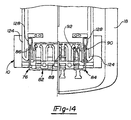
- Figure 14 is a cross-sectional view illustrating the interface between the cordless power tool and the converter.
- Figure 15 is a side view of a third cordless power tool of the system of the present invention.
- Figure 16 is a schematic representation illustrating the compatibility of the various batteries and tools of the present invention.
-
- With general reference to the drawings, a system of cordless power tools constructed in accordance with the teachings of a preferred embodiment of the present invention is illustrated. Exemplary cordless power tools of the system are shown to include, by way of examples, a circular power saw 10 (Figure 1), a reciprocating saw 12 (Figure 13), and a drill 14 (Figure 15). The tools 10-14 each include a conventional DC motor (not shown) adapted to be powered with a common voltage. In the exemplary embodiment, the tools 10-14 are intended to be driven by 24 volt electricity. It will become evident to those skilled that the present invention is not limited to the particular types of tools shown in the drawings nor to specific voltages. In this regard, the teachings of the present invention are applicable to virtually any type of power tool and any supply voltage.
- With continued reference to the drawings, the system of the present invention is additionally shown to generally include a first
rechargeable battery pack 16. The system of the present invention is further shown to generally include an AC/DC converter 18 and abattery charger 20 for charging thebattery pack 16. Thebattery charger 20 is shown in Figure 11 partially cut-away and operatively associated with thebattery pack 16. The AC/DC converter is shown in Figure 13 removably attached to thereciprocating saw 12. - The focus of the present invention most particularly pertains to the interfaces between the tools 10-14 and the
battery pack 16, the interfaces between tools 10-14 and the AC/DC converter 18, and the interfaces between thebattery pack 16 and thebattery charger 20. During the remainder of this detailed description, it will be understood that the tool interface of each of the tools 10-14 is substantially identical. - With particular reference to Figures 2-6, the
rechargeable battery pack 16 of the present invention is illustrated to generally include ahousing 22, abattery 24 which in the exemplary embodiment illustrated is a 24 volt nickel-cadmium battery, and a batterypack terminal block 26. Thehousing 22 is shown to include first and second clam shell halves 28 and 30 which are joined at a longitudinally extending partingline 32. Alternatively, it will be understood that thehousing 22 may include a pair of halves joined at a laterally extending parting line, or various other constructions including two or more housing portions. - The first and second clam shell halves 28 and 30 of the
housing 22 cooperate to form anupper portion 34 defining afirst chamber 36 and alower portion 38 defining asecond chamber 40. Thefirst chamber 36 receives the batterypack terminal block 26, while thesecond chamber 40 receives thebattery 24. The batterypack terminal block 26 is fixed against lateral and longitudinal movement relative to thehousing 22 except for minimal part tolerance stack up. In one application, thebattery pack housing 22 has an overall length of approximately 11.5 cm, an overall width of approximately 9.5 cm, and an overall height of approximately 9.5 cm. - In the exemplary embodiment, the first and second clam shell halves 28 and 30 of the
housing 22 are each unitarily constructed from a rigid plastic or other suitable material. The first and secondclam shell haves fasteners 42. The thread-formingfasteners 42 pass through cooperatingapertures 44 and screwboss portions 46 integrally formed with the clam shell halves 28 and 30. Upon assembly, thefasteners 42 form threads inscrew boss portions 46 ofhousing 30. In the exemplary embodiment illustrated, the firstclam shell half 28 of thehousing 22 is formed to include aperipheral groove 50 adapted to receive a mating rib (not specifically shown) peripherally extending about the secondclam shell half 30. - To facilitate releasable attachment of the
battery pack 16 to thetool 10, theupper portion 34 of thehousing 22 is formed to include a pair of guide rails 52. The guide rails 52, which will be described further below, are slidably received into cooperatinggrooves 54 defined byrails 55 formed in ahousing 56 of thetool 10. To further facilitate removable attachment of thebattery pack 16 to thetool 10, theupper portion 34 of thehousing 22 defines arecess 58. Therecess 58 is adapted to receive one ormore latch 59 carried by thehousing 56 of thetool 10. Thelatch 59 is conventional in construction and operation and is spring biased to a downward position so as to engage therecess 58 upon insertion with therechargeable battery pack 16. Removal of thebattery pack 16 is thereby prevented until the spring bias of thelatch 59 is overcome in a conventional manner insofar as the present invention is concerned. - With continued reference to Figures 2-5 and additional reference to Figures 7 and 8, the battery
pack terminal block 26 is illustrated to generally include amain body portion 60 constructed of rigid plastic or other suitable material and a plurality ofterminals 62. Theterminals 62 are generally planar-shaped blade terminals each oriented in a plane substantially perpendicular to a floor 64 (shown in Fig. 2) partially defining theupper chamber 36 of thehousing 22. Eachblade terminal 62 includes afirst end 66 which downwardly extends from themain body portion 60. Theblade terminals 62 each further include asecond end 68 which forwardly extends. In the preferred embodiment, the second ends 68 of theblade terminals 62 are upwardly spaced from thefloor 64. As will be appreciated more fully below, such spacing of theblade terminal 62 from thefloor 64 provides improved clearance around theblade terminals 62 and reduces the risk of contamination of theterminals 62 with dirt and other debris. In addition, such spacing of theterminals 62 from thefloor 64 allows the contacts of thecharger 20 to be more fully enclosed by insulating material. This aspect of the present invention will be discussed more further below. Further in the preferred embodiment, the front tips of theblade terminals 62 and the guide rails 52 are transversely aligned. - The
main body 60 of theterminal block 26 is shown captured between the clam shell halves 28 and 30 of thehousing 22. This arrangement improves assembly by allowing theterminal block 26 to first be electrically attached to thebattery 24 and subsequently captured between the clam shell halves 28 and 30. Themain body 60 is shown to include a pair ofarcuate grooves 70 provided in an under surface thereof for accommodating thescrew boss portions 46 of thehousing 20 upon assembly. Similarly, an upper side of themain body 60 includes arecess 72 for accommodating therecess 58 of thehousing 22. Themain body portion 60 is further shown to include a plurality of insulatingportions 74 interdisposed betweenadjacent blade terminal 62 and also positioned outboard of each of the outermostend blade terminals 62. The insulatingportions 74 protect theblade terminals 62 from incidental contact or damage. - In the exemplary embodiment illustrated, the battery
pack terminal block 26 includes fourblade terminals 62. Two of theblade terminals 62 are the positive and negative terminals for thebattery 24. Athird terminal 62 may be used to monitor temperature of thebattery 24 and a fourth terminal may be used for battery identification. The particular functions of the third andfourth blade terminals 62 are beyond the scope of the present invention and need not be described in detail herein. It will be appreciated by those skilled in the art thatadditional terminals 62 may be employed within the scope of the present invention. - With particular reference now to Figures 6A-B and 8, a
terminal block 76 carried by thetool 10 will be described. Thetool terminal block 76 is attached to thehousing 56 so as to prevent lateral movement relative to the housing except for part tolerance stack up. In the exemplary embodiment illustrated, thetool terminal block 76 is attached to thehousing 56 so as to also prevent longitudinal movement. However, as discussed below, certain applications may desire limited longitudinal translation of thetool terminal block 76. - The
tool terminal block 76 is illustrated to generally include amain body portion 80, a first ornegative terminal member 82, and a second orpositive terminal member 84. Thefirst terminal member 82 includes a negativemale terminal 86 and a negativefemale terminal 88. Similarly, the second terminal member includes a positivemale terminal 90 and a positivefemale terminal 92. As will be further discussed below, thefemale terminals negative blade terminals 62 of the batterypack terminal block 26. Themale terminals tool 10 to theconverter 18. As shown in Figure 8, when thebattery pack 16 is operatively attached to thetool 10, themale terminals tool terminal block 76 are received within clearances, shown in the exemplary embodiment asapertures 96, provided in each of therails 52. Alternatively, theclearances 96 to accommodate themale terminals rails 52 or the rails may be cut back. It will be understood that themale terminals battery pack 16 is attached to thetool 10. - As shown particularly in the end view of Figure 6B and the cross-sectional view of Figure 8, the
main body 80 of thetool terminal block 76 includes a plurality ofwindow frames 98 which each define a window or opening 100 for receiving and guiding one of theblade terminals 62. Thefemale terminals tool terminal block 76 are disposed within adjacent ones of the window frames 98. The window frames 98 are generally U-shaped and each include a pair of longitudinally extendinglegs 102 connected by anintermediate segment 103.Openings 104 are provided betweenadjacent window frames 98 for receiving the insulatingportions 74. In the exemplary embodiment, the ends of each of thelegs 102 of theframes 98 are generally triangular in shape so as to define lead-in surfaces for the insulatingportions 74 into theopenings 104 and also for theterminal blades 62 into theirrespective opening 100. - As shown most clearly in Figure 6B, the
main body portion 80 of thetool terminal block 76 includes a pair of laterally spaced rails 97. Themain body portion 80 further includes a pair ofapertures 101 which receive themale terminals rails 97 are adapted to be received withingrooves 99 provided in thehousing 30 of thebattery pack 16 immediately below the guide rails 52. As will be further discussed below, the laterally spacedrails 97 establish a tight fit with thegrooves 99 for precisely aligning thetool terminal block 76 with the batterypack terminal block 26. - With specific reference to Figure 11, a partially cutaway view of the
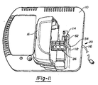
battery charger 20 of the system of the present invention is shown operatively associated with abattery pack 16 partially removed for purposes of illustration. Figure 12 is an elevated perspective view of thecharger 20 shown with thebattery pack 16 removed. In the preferred embodiment, thebattery charger 20 is a non-isolated charger. As used herein, the term non-isolated will be understood to mean that the output voltage is not isolated from the mains input voltage. Thebattery charger 20 includes ahousing 110 including an open recessed deck 111. Thebattery charger housing 110 further includes arear coupling section 112 for mechanically engaging theupper portion 34 of thebattery pack housing 22. - The
rear coupling section 112 includes a pair ofopposed grooves 54 similar to that provided in thetool housing 56 which receive the guide rails 52 of thebattery pack 22. Thebattery charger 20 further includes a set of female terminals having at least a pair offemale terminals 114 for receiving the positive andnegative blade terminals 62 of thebattery terminal pack 26. An electrical cord 116 provides AC electricity (for example, 120 volt electricity) to thebattery charger 20. Adjacent positioning of the positive and negativeterminal blades 62 permits a circuit layout of the charger which reduces electromagnetic interference. - The
battery charger housing 110 is shown most clearly in Figure 12 to define a plurality ofblade terminal openings 140 corresponding in number to theblade terminals 62 of thebattery pack 16. Theblade terminal openings 140 are defined by insulatingportions 142 adapted to cooperatively receive the insulatingportions 74 of thebattery pack 16. In this regard, adjacent insulatingportions 142 are spaced apart to defineopenings 144 for receiving the insulatingportions 74. The insulatingportions 142 of thecharger housing 110 each include a pair of vertically orientedsidewalls 146 and a horizontally orientedupper segment 148. Theupper segments 148 function to conceal theterminals 114 from incidental contact or damage. Since theblade terminals 62 of thebattery pack 16 are vertically spaced from thefloor 64, theupper segments 148 can be accommodated therebetween. It will be understood by those skilled in the art that the remainder of thebattery charger 20 is conventional in construction insofar as the present invention is concerned. - The
battery pack 16 is loaded into thecharger 20 by first vertically positioning thepack 16 on the deck 111 and then sliding thepack 16 rearward to engage therails 52 of thepack 16 with thegrooves 54 of thecharger 20. While on the deck 111, thepack 16 is supported byribs 113. The open deck 111 facilitates location of thepack 16 in thecharger 20 since thepack 16 is first grossly aligned with thecharger 20 through placement on the deck 111 and then mechanically and electrically connected through a rearward sliding action. A mechanical interface of improved stability is provided. In the event a user lifts thepack 16 andcharger 20 by gripping thepack 16 only, the engaged rails 52 andgrooves 54 avoid potentially damaging loads on the electrical terminals. Thus, the combination of the loading deck 111 and therear coupling section 112 provides improved loading ergonomics and mechanical stability of the connection. - Turning now to Figure 13, the
converter 18 of the system of the present invention is illustrated operatively attached to thereciprocating saw 12. Again, it will be appreciated by that theparticular tool 12 shown in Figure 12 is merely exemplary. In this regard, theconverter 18 is operative for use with thecircular saw 10 shown in Figure 1, thedrill 14 shown in Figure 15, or any other tool similar constructed in accordance with the teachings of the present invention. Theconverter 18 of Figure 13 is specifically adapted for converting main voltage AC electricity to 24 volt DC electricity. - In the preferred embodiment, the
converter 18 is a non-isolated converter and includes ahousing 120 and anelectrical power cord 122. Thehousing 120 is substantially similar to thehousing 22 of thebattery pack 16. In this regard, thehousing 120 includes first and second clam shell halves joined at a longitudinally extending parting line. Alternatively, thehousing 120 may include three (3) or more pieces. Anupper portion 122 of thehousing 120 includes a pair ofguide rails 124 similar to those of thebattery pack 16. - With continued reference to Figure 13 and additional reference to Figure 14, the
converter 18 is shown to include a pair offemale terminals 128 adapted to receive themale terminals tool terminal block 76. Thefemale terminals 128 are recessed within theupper portion 122 of thehousing 120 of theconverter 18. In the preferred embodiment, thefemale terminals 128 are recessed within thehousing 120 of theconverter 18 approximately 8mm or more. AC power is converted to DC power by theconverter 18 and delivered to thetool 12 through theterminals 128. When theconverter 18 is operatively installed on thetool 12, thefemale terminals tool terminal block 76 are electrically inoperative. - As discussed above, the exemplary tools 10-14 shown throughout the drawings are specifically designed to operate on 24 volt DC electricity. With reference to the schematic illustration of Figure 16, the system of the present invention is shown to further include second and third lines B and C of cordless power tools specifically intended for operation at alternate voltages. With the exception of their motors, the second and third lines B and C of power tools are substantially identical to the tools 10-14 of the first line A. For purposes of identification, the tools of the second and third lines B and C are denoted in the drawings with common reference numerals which are primed and double-primed, respectively. It will be understood that the tools 10'-14' and 10"-14"' are powered by second and third voltages, respectively. In the exemplary embodiment, the second and third voltages are lower and higher than the first voltage, respectively. The multiple lines A-C of tools operatively driven by different voltage values provide a consumer with a wide range of selection to accommodate particular power requirements.
- As shown in Figures 9 and 10, the system of the present invention is illustrated to include second and third battery packs 16' and 16" for providing electricity at the second and third voltages, respectively. The second and third battery packs 16' and 16" are substantially identical in construction to the
first battery pack 16. For this reason, reference numerals introduced above with respect to thefirst battery pack 16 will be used to identify common elements of the second and third battery packs 16' and 16". - The
third battery pack 16" differs from thefirst battery pack 16 in that itshousing 22 is substantially longer in a longitudinal direction so as to accommodate additional battery cells. In the exemplary embodiment, the width and height dimensions of thethird battery pack 16" are identical to corresponding dimensions of thefirst battery pack 16. Therails 52 of thethird battery pack 16" are correspondingly longer as are thegrooves 54 formed in thehousings 56 of thetools 10□-14□ of the third line. - The system of the present invention is intended to prevent operative engagement of any battery pack (e.g., 16 or 16") with a lower voltage value tool so as to protect the electric motors from damage. For example, the higher voltage
third battery pack 16" is intended to be locked out of both the tools 10-14 of the first line A and the tools 10'-14' of the second line B. In this regard, thehousing 22 of thethird battery pack 16" is shown to include a lock-outrib 130. In the embodiment illustrated, therib 130 extends approximately 86 millimeters from adatum wall 132 and is approximately two millimeters in height and two millimeters in width. Thedatum wall 132 normally limits translation of therails 52 relative to thegrooves 54. Anappropriate stop surface 133 will engage therib 130 and prevent engagement of thethird battery pack 16" which has a higher voltage with the terminal blocks 76 of the tools of the first and second lines A and B. - With particular reference to Figure 5, the
first battery pack 16 is designed to be locked out of the lower voltage tools 10'-14' of the second line B and will not be long enough to engage the terminal block of the third line C. Thefirst battery pack 16 has alockout rib 134 which extends approximately 14 millimeters from thedatum wall 132. Again, thelockout rib 134 is approximately two millimeters in height and two millimeters in width. While not specifically shown, it will be understood that thegrooves 54 of the tools 10-14 of the first line A are formed to accept thelockout rib 134 while the grooves of the tools of the lower voltage second line B are not. - With specific reference to Figure 9 illustrating the
second battery pack 16□, it will be understood that the second battery pack 16' is not specifically intended to be mechanically locked out of any of the tools of any of the lines A-C. However, the length of the battery pack 16', which in the preferred embodiment is identical to that of thefirst battery pack 16, is insufficient to engage the tool terminal block of the third line C of tools. The battery pack 16' is adapted to work in both the first and second tools lines A and B. In the alternative arrangement discussed above in which the higher voltagethird battery pack 16" has a length identical to that of the first and second battery packs 16 and 16', the low voltage second battery pack 16' would not need to be locked out of the tools of the higher voltage tool line C. However, sufficient power may not be available for intended usages. The dashed line between the battery packs 16 and 16' and the tools of the third line C shown in Figure 16 indicates this alternative where electrical engagement is not prevented. - Attachment of the
battery pack 16 to thehousing 56 automatically aligns or centers theblade terminals 62 of thebattery pack 16 with thefemale terminals tool terminal block 76. When thebattery pack 16 is inserted into thetool housing 56 the alignment ofpack terminal blades 62 and thefemale tool terminals mating tool grooves 54. The total travel of thebattery pack 16 relative to thehousing 56 is approximately 60 mm. In the second stage, which occurs during approximately the last 22 mm of travel of thepack 16 relative to thehousing 56, thegrooves 99 in thehousing 30 of thebattery pack 16 engage therails 97 of thetool terminal block 76 in a tight fit. In the preferred embodiment, thehousing 30 and the alignment rails 97 are in a snug fit. This engagement precisely aligns thebattery pack 16 with thetool terminal block 76 and in turn aligns thepack terminal block 26 with thetool terminal block 76. Normally, theblade terminals 62 of thepack 16 will engage thefemale tool terminals terminal blades 62 are bent, then theterminal blade 62 may engage an associatedwindow frame 98 of thetool terminal block 76. Thetapered legs 102 of theframe 98 may aid in straightening a slightlybent terminal blade 62. If theterminal blade 62 is severely bent, entry of theterminal blade 62 into theopening 100 is prevented by theframe 98. - As noted above, it may be alternatively desirable to permit the
tool terminal block 76 to longitudinally slide in thetool housing 56. When thepack terminal blades 62 are inserted in thefemale tool terminals pack terminal blades 62 engage thefemale tool terminals tool terminal block 76 rearwardly. For example, such translation may be on the order of approximately 2mm. When thetool terminal block 76 reaches its limit of travel relative to thetool housing 56, thepack terminals blades 62 are inserted between thefemale tool terminals pack blade terminals 62 are firmly gripped between thefemale tool terminals battery pack 16 moves relative to thetool housing 56 due to vibration of thetool 10 along an axis parallel to the guide rails 52, thepack 16 and thetool terminal block 76 move together. This conjoint movement of thetool terminal block 76 and thepack 16 may reduce wear on thepack terminal blades 62 andfemale tool terminals - With particular reference to Figure 2, the
battery pack 16 of the present invention is shown to includeprotrusions 160 to facilitate extraction of thebattery pack 16 from thetool housing 56 or from thecharger 20. In the exemplary embodiment, each of thehousing halves protrusions 160 disposed on a lateral side of thehousing 22 adjacent a rear side of thehousing 22. Eachprotrusion 160 is illustrated to be convexly curved and have a forward portion which the user may directly engage with a thumb or index finger. For example, the width of thebattery pack 16 permits the user to engage anupper protrusion 160 of thesecond housing half 30 with the right thumb and anupper protrusion 160 of thefirst housing half 28 with the right index finger. Thelower protrusions 160 may be used in a substantially similar manner when thebattery pack 16 is inverted in thecharger 20. - The present invention provides a number of advantages. One advantage of the present invention results from providing a battery pack for a cordless power tool with first and second housing halves and defining upper and lower chambers. A battery may be located in the lower chamber and a battery pack terminal block may be located in the upper chamber. Such a construction simplifies assembly, increases the durability of the pack and is particularly suitable for heavy packs having a large number of battery cells.
- A second advantage of the present invention results from providing a battery pack for a cordless power tool having longitudinally extending guide rails for engaging the tool and longitudinally extending terminal blades located between the rails. The front tips of the terminal blades and the guide rails have transversely aligned front tips. Such a construction simplifies and contributes to the precise alignment of the terminal blades with the guide rails thereby contributing to the alignment of the pack terminal blades with the tool terminals.
- A third advantage of the present invention results from providing a battery pack for a cordless power tool having a housing defining an upper chamber receiving a terminal block. The terminal block includes a plurality of pack terminals which are perpendicular to and spaced above a floor of the upper chamber thereby providing improved clearance around the terminals and also reducing the potential for contamination of the terminals with debris.
- A fourth advantage of the present invention results relates to a method of releasably and electrically interconnecting a battery pack with a too! terminal block of a cordless power tool. The battery pack is first roughly centered along a longitudinal axis of the tool handle through engagement of guide rails with the cooperating rails carried by the tool. Then the battery pack is finely centered through engagement of battery pack terminals through engagement of the tool terminal block with the battery pack.
- A fifth advantage of the present invention is to provide a battery pack for a cordless power tool which includes suitable protrusions to facilitate manual extraction.
- A sixth advantage of the present invention results from providing a system of cordless power tools including a rechargeable battery pack having male or projecting terminals (for connecting to recessed or female terminals of a tool and to recessed or female terminals of a charger), a non-isolated AC/DC converter having recessed or female terminals for interfacing with the tool, and a non-isolated charger having recessed terminals for interfacing with the battery pack. The use of nonisolated (compared to isolated) components simplify construction and reduce cost. The invention provides a converter with female terminals and a pack with male terminals that are mechanically and electrically compatible with a tool having both male and female terminals. This enables the system to be powered with a cordless DC pack or a corded AC/DC converter and gives the user flexibility in the choice of power sources.
- A seventh advantage of the present invention results from providing a system of cordless power tools including a charger having a housing with an open recessed deck for vertically receiving a rechargeable battery pack and a coupling portion (preferably, grooves) for mechanically aligning the battery pack and the charger terminals and also connecting the battery pack mechanically in the charger such that longitudinal translation of the battery pack toward the coupling portion prevents vertical displacement of the battery pack relative to the housing. Vertical loading of the pack to an open charger deck initially prior to engaging the pack rails in the mating grooves of the charger simplifies alignment of the pack with the charger grooves. This method is particularly suitable for large heavy battery packs.
- While the invention has been described in the specification and illustrated in the drawings with reference to a preferred embodiment, it will be understood by those skilled in the art that various changes may be made and equivalents may be substituted for elements thereof without departing from the scope of the invention as defined in the claims. In addition, many modifications may be made to adapt a particular situation or material to the teachings of the invention without departing from the essential scope thereof. Therefore, it is intended that the invention not be limited to the particular embodiment illustrated by the drawings and described in the specification as the best mode presently contemplated for carrying out this invention, but that the invention will include any embodiments falling within the description of the appended claims.
Claims (25)
- A battery pack 16 for a cordless power tool 10 having a tool housing 56, the battery pack 16 characterized by:a battery pack housing 22 having first and second halves 28 and 30 defining first and second chambers 36 and 40;a battery 24 disposed in the second chamber 40; anda battery pack terminal block 26 electrically connected to the battery 24, the battery pack terminal block 26 disposed in the first chamber 36 and captured between the first and second halves 28 and 30.
- The battery pack 16 for a cordless power tool 10 of claim 1, wherein the first and second halves 28 and 30 interface along a longitudinally extending centerline 32 of the battery pack 16.
- The battery pack 16 for a cordless power tool 10 of claim 1, wherein the battery pack terminal block 26 includes a plurality of terminal blades 62 longitudinally extending in a direction parallel to an upper surface of the battery pack 16.
- The battery pack 16 for a cordless power tool 10 of claim 1, wherein the battery pack housing 22 includes first and second longitudinally extending guide rails 52 adapted to slidably engage the housing 56 of the cordless power tool 10.
- The battery pack 16 for a cordless power tool 10 of claim 4, wherein the battery pack terminal block 26 is transversely disposed between the guide rails 52 and includes a plurality of longitudinally extending terminal blades 62, the guide rails 52 and the plurality of terminal blades 62 including transversely aligned forward ends.
- The battery pack 16 for a cordless power tool 10 of claim 1, wherein the first chamber 36 has a floor 64 and the terminal block 26 includes a plurality of terminal blades 62 each spaced from the floor 64.
- The battery pack 16 for a cordless power tool 10 of claim 1, wherein the battery pack housing 22 includes first and second laterally spaced sides and a rear side oriented substantially perpendicular thereto, and further wherein the battery pack housing 22 includes first and second protrusions 160 disposed adjacent the rear side on the first and second laterally spaced sides, respectively, both of the first and second protrusions 160 being generally convexly curved and adapted to facilitate manual extraction of the battery pack 16 from the cordless power tool 10.
- The battery pack 16 for a cordless power tool 10 of claim 4, in combination with the power tool 10, the power tool 10 including a tool terminal block 76 having a pair of male terminals 86 and 90 and a pair of female terminals 88 and 92, the male terminals 86 and 90 operative for use with an AC/DC converter 18, the pair of female terminals 88 and 92 each adapted to receive one of a positive and negative terminal 62 of the battery pack terminal block 26, the guide rails 52 each formed to include an aperture 96 for non-operatively receiving an associated one of the pair of male terminals 86 and 90.
- A cordless power tool system characterized by:a rechargeable battery pack 16 having a battery pack terminal block 26 including a positive terminal blade 62 and a negative terminal blade 62;an AC/DC converter 18 having a converter housing 120 and further having positive and negative female terminals 128, the positive and negative female terminals 128 being recessed within the converter housing 120 and being adapted to receive the positive and negative terminal blades 62, respectively; anda cordless power tool 10 having a housing 56 and positive and negative male terminals 86 and 90 for engaging the positive and negative female terminals 128 of the converter 18, respectively, the cordless power tool 10 further having positive and negative female terminals 88 and 92 adapted to receive the positive and negative terminal blades 62, respectively, the positive and negative female terminals 88 and 92 of the tool 10 being recessed within the housing 56 of the tool 10.
- The cordless power tool system of claim 9, wherein the battery pack housing 22 includes:first and second halves 28 and 30 defining first and second chambers 36 and 40;a battery 24 disposed in the second chamber 40; anda battery pack terminal block 26 including the positive terminal blade 62 and the negative terminal blade 62, the battery pack terminal block 26 electrically connected to the battery 24, the battery pack terminal block 26 disposed in the first chamber 36 and captured between the first and second halves 28 and 30.
- The battery pack 16 for a cordless power tool 10 of claim 10, wherein the first and second halves 28 and 30 interface along a longitudinally extending centerline 32 of the battery pack 16.
- The cordless power tool system of claim 9, wherein the battery pack housing 22 includes first and second longitudinally extending guide rails 52 adapted to slidably engage the cordless power tool 10.
- The cordless power tool system of claim 12, wherein the battery pack terminal block 26 is transversely disposed between the guide rails 52.
- The cordless power tool system of claim 13, wherein the guide rails 52 and the positive and negative terminal blades 62 have transversely aligned forward ends.
- The cordless power tool system of claim 9 wherein the first chamber 36 has a floor 64 and the positive and negative terminal blades 62 of the battery pack terminal block 26 are spaced from the floor 64.
- The cordless power tool system of claim 9, wherein the battery pack housing 22 includes first and second laterally spaced sides and a rear side oriented substantially perpendicular thereto, and further wherein the battery pack housing 22 includes first and second protrusions 160 disposed adjacent the rear side on the first and second laterally spaced sides, respectively, both of the first and second protrusions 160 being generally convexly curved and adapted to facilitate manual extraction of the battery pack 16 from the cordless power tool 10.
- The cordless power tool system of claim 12, wherein the guide rails 52 are each formed to include an aperture 96 for non-operatively receiving an associated one of the pair of male terminals 86 and 90.
- The cordless power tool system of claim 9, further characterized by a battery charger 20 including a housing 110 and positive and negative female terminals 114 for receiving the positive and negative terminal blades 62, respectively, the housing 110 including an open deck portion 111 for vertically receiving the battery pack 16 and a coupling portion 112 for mechanically engaging the battery pack 16, the coupling portion 112 defining a pair of laterally spaced grooves 54 for receiving the pair of laterally spaced guide rails 55 such that longitudinal translation of the battery pack 16 toward the coupling portion 112 prevents vertical displacement of the battery pack 16 relative to the housing 56.
- The cordless power tool system of claim 9, wherein the converter housing 120 includes first and second halves joined along a longitudinally extending parting line.
- The cordless power tool system of claim 9, wherein the converter housing 120 includes first and second longitudinally extending guide rails 124 for slidably engaging the housing 56 of the cordless power tool 10.
- The cordless power tool system of claim 9, wherein the positive and negative female terminals 128 are recessed within the converter housing 120 at least approximately 8mm.
- A method of releasable and electrically interconnecting a battery pack 16 with a tool terminal block 76 of a cordless power tool 10, the cordless power tool 10 having a housing 56 defining a pair of tool grooves 54, the tool terminal block 76 including a pair of female terminals 88 and 92 and a pair of laterally spaced battery pack guide rails 52, the method characterized by the steps of:providing a rechargeable battery pack 16 including a pair of laterally spaced apart battery pack guide rails 52 which define a pair of battery pack grooves 99 subjacent to the battery pack guide rails 52, the battery pack 16 further including a battery pack terminal block 26 for interfacing with the tool terminal block 76, the battery pack terminal block 26 including a pair of terminal blades 62;grossly aligning the tool terminal block 76 and the battery pack terminal block 26 by engaging the battery pack guide rails 52 and tool grooves 54 in a generally loose fit and subsequently sliding the battery pack guide rails 52 relative to the tool grooves 54 a first distance; andprecisely aligning the battery pack 16 relative to the tool terminal block 76 by sliding the guide rails 52 relative to the grooves 54 a second, additional predetermined distance such that the battery pack guide rails 52 engage the pair of battery pack grooves 54 in a generally tight fit.
- The method of claim 22, further include the step of engaging the terminal blades 62 with the female terminals 88 and 92 after the step of precisely aligning the battery pack 16 relative to the tool terminal block 76.
- The method of claim 22, wherein the tool terminal block 76 includes a window frame 98 associated with each female terminal 88 and 92, each window frame 98 defining a tapered opening 100 for receiving one of the terminal blades 62.
- The method of claim 24, further characterized by the step of straightening one of the terminal blades 62 with one of the window frames 98.
Priority Applications (2)
| Application Number | Priority Date | Filing Date | Title |
|---|---|---|---|
| EP06111072A EP1696498B1 (en) | 1998-08-13 | 1999-08-13 | Cordless power tool system |
| EP06111075A EP1699097B8 (en) | 1998-08-13 | 1999-08-13 | Cordless power tool system |
Applications Claiming Priority (3)
| Application Number | Priority Date | Filing Date | Title |
|---|---|---|---|
| US09/133,924 US6057608A (en) | 1998-08-13 | 1998-08-13 | Cordless power tool system |
| US133924 | 1999-08-13 | ||
| EP99306420A EP1076370B1 (en) | 1998-08-13 | 1999-08-13 | Cordless power tool system |
Related Parent Applications (2)
| Application Number | Title | Priority Date | Filing Date |
|---|---|---|---|
| EP99306420A Division-Into EP1076370B1 (en) | 1998-08-13 | 1999-08-13 | Cordless power tool system |
| EP99306420A Division EP1076370B1 (en) | 1998-08-13 | 1999-08-13 | Cordless power tool system |
Related Child Applications (2)
| Application Number | Title | Priority Date | Filing Date |
|---|---|---|---|
| EP06111072A Division EP1696498B1 (en) | 1998-08-13 | 1999-08-13 | Cordless power tool system |
| EP06111075A Division EP1699097B8 (en) | 1998-08-13 | 1999-08-13 | Cordless power tool system |
Publications (3)
| Publication Number | Publication Date |
|---|---|
| EP1363340A2 true EP1363340A2 (en) | 2003-11-19 |
| EP1363340A3 EP1363340A3 (en) | 2004-01-28 |
| EP1363340B1 EP1363340B1 (en) | 2006-06-21 |
Family
ID=22460936
Family Applications (5)
| Application Number | Title | Priority Date | Filing Date |
|---|---|---|---|
| EP03017177A Expired - Lifetime EP1363339B1 (en) | 1998-08-13 | 1999-08-13 | Cordles power tool system |
| EP06111072A Expired - Lifetime EP1696498B1 (en) | 1998-08-13 | 1999-08-13 | Cordless power tool system |
| EP06111075A Expired - Lifetime EP1699097B8 (en) | 1998-08-13 | 1999-08-13 | Cordless power tool system |
| EP03017178A Expired - Lifetime EP1363340B1 (en) | 1998-08-13 | 1999-08-13 | Cordless power tool system |
| EP99306420A Expired - Lifetime EP1076370B1 (en) | 1998-08-13 | 1999-08-13 | Cordless power tool system |
Family Applications Before (3)
| Application Number | Title | Priority Date | Filing Date |
|---|---|---|---|
| EP03017177A Expired - Lifetime EP1363339B1 (en) | 1998-08-13 | 1999-08-13 | Cordles power tool system |
| EP06111072A Expired - Lifetime EP1696498B1 (en) | 1998-08-13 | 1999-08-13 | Cordless power tool system |
| EP06111075A Expired - Lifetime EP1699097B8 (en) | 1998-08-13 | 1999-08-13 | Cordless power tool system |
Family Applications After (1)
| Application Number | Title | Priority Date | Filing Date |
|---|---|---|---|
| EP99306420A Expired - Lifetime EP1076370B1 (en) | 1998-08-13 | 1999-08-13 | Cordless power tool system |
Country Status (8)
| Country | Link |
|---|---|
| US (1) | US6057608A (en) |
| EP (5) | EP1363339B1 (en) |
| JP (1) | JP4741048B2 (en) |
| AT (5) | ATE434271T1 (en) |
| DE (5) | DE69941018D1 (en) |
| DK (2) | DK1363340T3 (en) |
| ES (2) | ES2247461T3 (en) |
| PT (1) | PT1363340E (en) |
Cited By (3)
| Publication number | Priority date | Publication date | Assignee | Title |
|---|---|---|---|---|
| DE102004030037B4 (en) * | 2003-11-19 | 2012-01-12 | Milwaukee Electric Tool Corp. | accumulator |
| US8487585B2 (en) | 2002-11-22 | 2013-07-16 | Milwaukee Electric Tool Corporation | Battery pack |
| US10218194B2 (en) | 2002-11-22 | 2019-02-26 | Milwaukee Electric Tool Corporation | Lithium-based battery pack for a hand held power tool |
Families Citing this family (99)
| Publication number | Priority date | Publication date | Assignee | Title |
|---|---|---|---|---|
| US6996909B1 (en) * | 1998-08-13 | 2006-02-14 | Black & Decker Inc. | Battery powered circular saw |
| US6304058B2 (en) * | 1998-08-13 | 2001-10-16 | Black & Decker Inc. | Cordless power tool system |
| JP3698296B2 (en) * | 1999-08-19 | 2005-09-21 | 株式会社マキタ | Terminal structure |
| JP3792967B2 (en) * | 1999-11-15 | 2006-07-05 | 株式会社マキタ | Battery pack and power tool |
| US6286609B1 (en) * | 1999-12-10 | 2001-09-11 | Black & Decker Inc. | AC/DC chopper for power tool |
| US7443137B2 (en) | 2000-08-11 | 2008-10-28 | Milwaukee Electric Tool Corporation | Adapter for a power tool battery |
| US7183745B2 (en) * | 2000-08-11 | 2007-02-27 | Milwaukee Electric Tool Corporation | Adapter for a power tool battery |
| US6525511B2 (en) | 2000-08-11 | 2003-02-25 | Milwaukee Electric Tool Corporation | Adapter for a power tool battery |
| US20020125857A1 (en) * | 2001-03-09 | 2002-09-12 | Thomas Mastaler | Battery adapter for a cordless power tool system and related method |
| JP4121945B2 (en) * | 2001-05-28 | 2008-07-23 | 10チャージ エレクトロテクニカイ フェレストウー エシュ ケレシュケデルミ ケイエフテイ | Method and apparatus for charging a rechargeable battery with a non-liquid electrolyte |
| EP1411564B1 (en) | 2001-07-24 | 2009-12-02 | Sony Corporation | Method for preventing erroneous mounting of mounting part on main body device, mounting part and battery pack used for this |
| CN1812162B (en) * | 2001-07-25 | 2016-01-20 | 索尼公司 | For loading battery device on the electronic device |
| US6729413B2 (en) | 2001-08-24 | 2004-05-04 | Black & Decker Inc. | Power tool with battery pack ejector |
| US6781249B2 (en) * | 2001-08-29 | 2004-08-24 | Hewlett-Packard Development Company, L.P. | Retrofittable power supply |
| US20050083639A1 (en) * | 2001-11-09 | 2005-04-21 | Zick Jonathan A. | Electrical component, such as a radio, MP3 player, audio component, battery charger, radio/charger, MP3 player/radio, MP3 player/charger or MP3 player/radio/charger, having a selectively connectable battery charger |
| US7609027B2 (en) | 2001-11-09 | 2009-10-27 | Milwaukee Electric Tool Corporation | Electrical component, audio component, or electrical combination having a selectively connectable battery charger |
| US7332889B2 (en) * | 2001-11-09 | 2008-02-19 | Milwaukee Electric Tool Corporation | Battery charger |
| DE10229980A1 (en) * | 2002-07-03 | 2004-01-15 | Hilti Ag | battery pack |
| US6924620B2 (en) * | 2002-07-25 | 2005-08-02 | Milwaukee Electric Tool Corporation | Battery, battery charger, electrical system and method of charging a battery |
| US7581323B2 (en) | 2002-09-17 | 2009-09-01 | Credo Technology Corporation | Cordless circular saw |
| USD489591S1 (en) | 2002-10-01 | 2004-05-11 | Milwaukee Electric Tool Corporation | Circular saw |
| US20050044051A1 (en) * | 2003-08-22 | 2005-02-24 | Selby David A. | Combo kit and method of providing a combo kit |
| US20050267776A1 (en) * | 2003-08-22 | 2005-12-01 | Selby David A | Combo kit and method of providing a combo kit |
| US20050078834A1 (en) * | 2003-10-14 | 2005-04-14 | Credo Technology Corporation | Portable battery charging and audio unit |
| US8604752B2 (en) * | 2003-10-14 | 2013-12-10 | Robert Bosch Gmbh | Portable battery charging and audio unit |
| US7835534B2 (en) * | 2003-10-14 | 2010-11-16 | Robert Bosch Gmbh | Battery charging jobsite lunchbox |
| JP4123516B2 (en) | 2003-12-26 | 2008-07-23 | ソニー株式会社 | Battery device |
| JP4123515B2 (en) | 2003-12-26 | 2008-07-23 | ソニー株式会社 | Battery device |
| JP4123517B2 (en) | 2003-12-26 | 2008-07-23 | ソニー株式会社 | Battery device |
| WO2005099043A2 (en) * | 2004-03-31 | 2005-10-20 | Black & Decker Inc. | Battery pack - cordless power device interface system |
| US20060087283A1 (en) * | 2004-10-18 | 2006-04-27 | Phillips Steven J | Cordless power system |
| US7273159B2 (en) * | 2004-11-08 | 2007-09-25 | Black & Decker Inc. | Cordless power tool system with improved power output |
| US7327120B2 (en) * | 2004-12-29 | 2008-02-05 | Techway Industrial Co., Ltd. | Charger assembly for a power cell for an electrical tool |
| CN2762964Y (en) * | 2005-01-10 | 2006-03-08 | 南京德朔实业有限公司 | Electric tool power supplied by battery |
| US20060090354A1 (en) * | 2005-03-28 | 2006-05-04 | Gongola Andrew G | Power tool, such as a circular saw |
| DE102006023187B4 (en) | 2005-05-17 | 2020-02-27 | Milwaukee Electric Tool Corp. | Method for operating a battery charger and a combination comprising a battery and a battery charger |
| DE102006023188A1 (en) | 2005-05-17 | 2007-01-11 | Milwaukee Electric Tool Corp., Brookfield | Power tool, battery, charger and method of operation thereof |
| JP4999284B2 (en) * | 2005-05-19 | 2012-08-15 | 日本電産テクノモータ株式会社 | Battery pack, power tool and charger |
| DE102005045656A1 (en) * | 2005-09-13 | 2007-03-15 | Alfred Kärcher Gmbh & Co. Kg | Rechargeable battery |
| US7497275B2 (en) * | 2005-11-04 | 2009-03-03 | Black & Decker Inc. | Cordless power tool system with improved power output |
| US20070240892A1 (en) * | 2005-11-04 | 2007-10-18 | Black & Decker Inc. | Cordless outdoor power tool system |
| US7741809B2 (en) * | 2006-01-06 | 2010-06-22 | Milwaukee Electric Tool Corporation | Electrical component including a battery receptacle for including a battery |
| US9533367B2 (en) | 2006-05-04 | 2017-01-03 | Black & Decker Inc. | Cordless welding machine and plasma cutter |
| US20070277987A1 (en) * | 2006-05-26 | 2007-12-06 | Meyer Gary D | Power tool, battery pack, and method of operating the same |
| US11196121B2 (en) | 2006-08-28 | 2021-12-07 | Sony Corporation | Battery device, electronic apparatus, and battery system |
| JP4245017B2 (en) | 2006-08-28 | 2009-03-25 | ソニー株式会社 | Battery device, electronic device and battery system |
| JP4311425B2 (en) | 2006-09-07 | 2009-08-12 | 日立工機株式会社 | Battery pack, charger, and power tool |
| US7659694B2 (en) * | 2006-10-02 | 2010-02-09 | Snap-On Incorporated | Self-aligning terminal block for battery pack |
| US7719230B2 (en) * | 2006-10-27 | 2010-05-18 | Snap-On Incorporated | Kit of power tools |
| US8228029B2 (en) * | 2007-02-23 | 2012-07-24 | Milwaukee Electric Tool Corporation | Power tool, battery pack, and method of operating the same |
| DE202007005373U1 (en) * | 2007-04-12 | 2008-08-21 | Weidmüller Interface GmbH & Co. KG | Modular terminal block system |
| WO2008133340A1 (en) * | 2007-04-23 | 2008-11-06 | Hitachi Koki Co., Ltd. | Battery pack and battery-driven power tool using the same |
| JP5370709B2 (en) | 2007-10-29 | 2013-12-18 | 日立工機株式会社 | Battery pack and electric tool equipped with the same |
| US20080305387A1 (en) * | 2007-06-11 | 2008-12-11 | Black & Decker Inc. | Cordless power tool system |
| GB2457173A (en) * | 2008-02-11 | 2009-08-12 | Milwaukee Electric Tool Corp | A Power Tool |
| EP2110921B1 (en) | 2008-04-14 | 2013-06-19 | Stanley Black & Decker, Inc. | Battery management system for a cordless tool |
| JP5355999B2 (en) * | 2008-11-25 | 2013-11-27 | 株式会社マキタ | Battery pack |
| JP5083630B2 (en) * | 2009-03-13 | 2012-11-28 | 日立工機株式会社 | Battery pack, power tool, charger |
| DE102009028945C5 (en) * | 2009-08-27 | 2013-08-08 | Hilti Aktiengesellschaft | Hand welder |
| DE102010003283A1 (en) * | 2010-03-25 | 2011-09-29 | Robert Bosch Gmbh | Hand machine tool battery device |
| JP3160044U (en) | 2010-03-29 | 2010-06-10 | ソニー株式会社 | Power supply device |
| US9722334B2 (en) * | 2010-04-07 | 2017-08-01 | Black & Decker Inc. | Power tool with light unit |
| JP5523905B2 (en) * | 2010-04-13 | 2014-06-18 | 株式会社マキタ | Terminal connection structure |
| US20110317064A1 (en) * | 2010-06-24 | 2011-12-29 | Watts Fred S | Remote Inspection Device |
| US9028272B2 (en) * | 2010-08-31 | 2015-05-12 | Makita Corporation | Foreign material removing structure for charger |
| US9545687B2 (en) | 2010-12-17 | 2017-01-17 | Hobart Brothers Company | Spool gun adapter |
| US20120241431A1 (en) * | 2011-03-25 | 2012-09-27 | Hobart Brothers Company | Welding arc powered spool gun |
| JP2013242992A (en) * | 2012-05-18 | 2013-12-05 | Makita Corp | Battery pack, and rechargeable electrical equipment system |
| EP2712713A1 (en) * | 2012-10-01 | 2014-04-02 | Guido Valentini | Electronically driven mobile equipment comprising a battery pack and electronic power supply unit for use with such a mobile equipment |
| US9065106B2 (en) * | 2012-10-17 | 2015-06-23 | Black & Decker Inc. | Battery pack with guide rails for improved terminal alignment |
| WO2014063042A1 (en) | 2012-10-19 | 2014-04-24 | Milwaukee Electric Tool Corporation | Visual inspection device |
| JP5605588B2 (en) * | 2012-12-21 | 2014-10-15 | 日立工機株式会社 | Battery pack and electric tool equipped with the same |
| US9511921B2 (en) * | 2013-03-15 | 2016-12-06 | Milwaukee Electric Tool Corporation | Heated utility bag |
| WO2014161257A1 (en) | 2013-04-04 | 2014-10-09 | Milwaukee Electric Tool Corporation | Power tool |
| JP5490943B2 (en) * | 2013-05-28 | 2014-05-14 | リョービ株式会社 | Battery pack |
| US10027078B2 (en) | 2014-01-02 | 2018-07-17 | Sears Brands, L.L.C. | Slide battery and power tool for use with both slide and post batteries |
| GB201403971D0 (en) | 2014-03-06 | 2014-04-23 | 7Rdd Ltd | Portable power supply improvements |
| US9893384B2 (en) | 2014-05-18 | 2018-02-13 | Black & Decker Inc. | Transport system for convertible battery pack |
| US9406915B2 (en) | 2014-05-18 | 2016-08-02 | Black & Decker, Inc. | Power tool system |
| DE102014211046A1 (en) * | 2014-06-10 | 2015-12-17 | Robert Bosch Gmbh | System comprising at least one electronically commutated electric motor of a defined size and a rechargeable battery of at least one voltage class |
| AU2015354771B2 (en) | 2014-11-26 | 2018-07-26 | Techtronic Industries Co. Ltd. | Battery pack |
| DE202015104371U1 (en) | 2015-08-18 | 2015-09-02 | Kompernaß Handelsgesellschaft mbH | Adapter for a power tool |
| JP6713318B2 (en) * | 2015-12-01 | 2020-06-24 | 株式会社マキタ | Battery mounter |
| DE102016201802A1 (en) * | 2015-12-22 | 2017-06-22 | Robert Bosch Gmbh | Hand tool |
| US10553843B2 (en) | 2016-03-28 | 2020-02-04 | Transform Sr Brands Llc | Portable power tool, battery pack, and cell configurations for same |
| DE102016214106A1 (en) * | 2016-08-01 | 2018-02-01 | Robert Bosch Gmbh | Contact holder device for a hand tool machine |
| JP6729711B2 (en) * | 2016-10-31 | 2020-07-22 | 工機ホールディングス株式会社 | Battery pack and electrical equipment using battery pack |
| CN106601953B (en) * | 2016-12-19 | 2023-04-18 | 南京九致信息科技有限公司 | Electric automobile trades electric battery compartment device with cooling system |
| EP3560062A4 (en) | 2016-12-23 | 2020-06-24 | Black & Decker Inc. | Cordless power tool system |
| DE102017210467A1 (en) * | 2017-06-22 | 2018-12-27 | Robert Bosch Gmbh | Hand tool |
| WO2019214447A1 (en) | 2018-05-07 | 2019-11-14 | 苏州宝时得电动工具有限公司 | Battery pack and electric tool assembly |
| CN210610343U (en) | 2018-09-27 | 2020-05-26 | 南京德朔实业有限公司 | Lawn mower and blade assembly suitable for lawn mower |
| CA3114468C (en) | 2018-09-27 | 2022-04-12 | Nanjing Chervon Industry Co., Ltd. | Lawn mower |
| TWM612458U (en) | 2019-03-12 | 2021-06-01 | 美商米沃奇電子工具公司 | Power tool |
| USD995569S1 (en) | 2019-04-18 | 2023-08-15 | Nanjing Chervon Industry Co., Ltd. | Mower blade assembly |
| USD892586S1 (en) | 2019-04-18 | 2020-08-11 | Harbor Freight Tools Usa, Inc. | Power tool |
| CN212659643U (en) * | 2019-06-11 | 2021-03-05 | 南京德朔实业有限公司 | Battery pack, battery pack communication terminal, and combination of battery pack and electric power tool |
| JP7423775B2 (en) | 2019-12-03 | 2024-01-29 | ミルウォーキー エレクトリック ツール コーポレイション | Battery pack and charger system |
| TWI779431B (en) * | 2020-12-18 | 2022-10-01 | 東友科技股份有限公司 | Drone and battery exchange system thereof |
Citations (8)
| Publication number | Priority date | Publication date | Assignee | Title |
|---|---|---|---|---|
| US3887394A (en) * | 1973-09-04 | 1975-06-03 | Mallory & Co Inc P R | Battery cartridge with hollow case of minimum weight and dimensions |
| US3952239A (en) * | 1974-08-23 | 1976-04-20 | The Black And Decker Manufacturing Company | Modular cordless tools |
| US5391972A (en) * | 1988-03-11 | 1995-02-21 | Gardner; Billy J. | Cordless tool battery housing and charging system |
| US5508123A (en) * | 1995-03-06 | 1996-04-16 | Wey Henn Co., Ltd. | Power supplying device |
| US5792573A (en) * | 1994-06-10 | 1998-08-11 | Pitzen; James F. | Rechargeable battery adapted to be attached to orthopedic device |
| US6075341A (en) * | 1999-02-17 | 2000-06-13 | Black & Decker Inc. | Power pack charging system for a power tool |
| EP1017149A2 (en) * | 1998-12-30 | 2000-07-05 | Black & Decker Inc. | Dual-mode non-isolated corded system for portable cordless power tools |
| EP1025961A1 (en) * | 1999-01-29 | 2000-08-09 | Black & Decker Inc. | Battery powered hand guided power tool |
Family Cites Families (13)
| Publication number | Priority date | Publication date | Assignee | Title |
|---|---|---|---|---|
| US3757194A (en) * | 1972-07-03 | 1973-09-04 | Black & Decker Mfg Co | Cordless power tool having removable battery pack |
| GB1422759A (en) * | 1973-06-08 | 1976-01-28 | Wolf Geraete Gmbh | Battery power pack |
| US3973179A (en) * | 1974-08-23 | 1976-08-03 | The Black And Decker Manufacturing Company | Modular cordless tools |
| US4321523A (en) * | 1978-10-05 | 1982-03-23 | The Gates Rubber Company | Battery charger and power supply circuitry |
| US4616169A (en) * | 1985-04-08 | 1986-10-07 | Scovill Inc. | Battery-powered appliance |
| DE3815651A1 (en) * | 1988-05-07 | 1989-11-16 | Scintilla Ag | MOTORIZED GRASS SHEARS |
| JPH0735649Y2 (en) * | 1989-06-29 | 1995-08-16 | 白光株式会社 | Nozzle for desoldering device |
| US5280525A (en) * | 1991-09-27 | 1994-01-18 | At&T Bell Laboratories | Adaptive frequency dependent compensation for telecommunications channels |
| GB2269475B (en) * | 1992-08-06 | 1996-05-01 | Gsl Rechargeable Products Limi | Battery operated electrical device |
| JPH08290371A (en) * | 1995-02-23 | 1996-11-05 | Makita Corp | Connecting structure of battery pack in electric tool |
| DE19521423B4 (en) * | 1995-06-14 | 2006-08-31 | Robert Bosch Gmbh | Hand tool with battery-powered drive motor and battery assembly for such a hand tool |
| DE19521426B4 (en) * | 1995-06-14 | 2006-04-27 | Robert Bosch Gmbh | Hand tool with battery powered drive motor |
| US5589288A (en) * | 1995-07-31 | 1996-12-31 | Black & Decker, Inc. | Cordless power tool having a push button battery release arrangement |
-
1998
- 1998-08-13 US US09/133,924 patent/US6057608A/en not_active Expired - Lifetime
-
1999
- 1999-08-13 ES ES03017177T patent/ES2247461T3/en not_active Expired - Lifetime
- 1999-08-13 PT PT03017178T patent/PT1363340E/en unknown
- 1999-08-13 AT AT06111075T patent/ATE434271T1/en not_active IP Right Cessation
- 1999-08-13 AT AT99306420T patent/ATE286304T1/en not_active IP Right Cessation
- 1999-08-13 EP EP03017177A patent/EP1363339B1/en not_active Expired - Lifetime
- 1999-08-13 AT AT03017178T patent/ATE331306T1/en not_active IP Right Cessation
- 1999-08-13 DK DK03017178T patent/DK1363340T3/en active
- 1999-08-13 AT AT03017177T patent/ATE308121T1/en not_active IP Right Cessation
- 1999-08-13 JP JP22915199A patent/JP4741048B2/en not_active Expired - Fee Related
- 1999-08-13 EP EP06111072A patent/EP1696498B1/en not_active Expired - Lifetime
- 1999-08-13 EP EP06111075A patent/EP1699097B8/en not_active Expired - Lifetime
- 1999-08-13 EP EP03017178A patent/EP1363340B1/en not_active Expired - Lifetime
- 1999-08-13 DE DE69941018T patent/DE69941018D1/en not_active Expired - Lifetime
- 1999-08-13 ES ES03017178T patent/ES2266694T3/en not_active Expired - Lifetime
- 1999-08-13 DE DE69928031T patent/DE69928031T2/en not_active Expired - Lifetime
- 1999-08-13 EP EP99306420A patent/EP1076370B1/en not_active Expired - Lifetime
- 1999-08-13 DE DE69936240T patent/DE69936240T2/en not_active Expired - Lifetime
- 1999-08-13 DE DE69922948T patent/DE69922948T2/en not_active Expired - Lifetime
- 1999-08-13 AT AT06111072T patent/ATE363735T1/en not_active IP Right Cessation
- 1999-08-13 DK DK03017177T patent/DK1363339T3/en active
- 1999-08-13 DE DE69932104T patent/DE69932104T2/en not_active Expired - Lifetime
Patent Citations (8)
| Publication number | Priority date | Publication date | Assignee | Title |
|---|---|---|---|---|
| US3887394A (en) * | 1973-09-04 | 1975-06-03 | Mallory & Co Inc P R | Battery cartridge with hollow case of minimum weight and dimensions |
| US3952239A (en) * | 1974-08-23 | 1976-04-20 | The Black And Decker Manufacturing Company | Modular cordless tools |
| US5391972A (en) * | 1988-03-11 | 1995-02-21 | Gardner; Billy J. | Cordless tool battery housing and charging system |
| US5792573A (en) * | 1994-06-10 | 1998-08-11 | Pitzen; James F. | Rechargeable battery adapted to be attached to orthopedic device |
| US5508123A (en) * | 1995-03-06 | 1996-04-16 | Wey Henn Co., Ltd. | Power supplying device |
| EP1017149A2 (en) * | 1998-12-30 | 2000-07-05 | Black & Decker Inc. | Dual-mode non-isolated corded system for portable cordless power tools |
| EP1025961A1 (en) * | 1999-01-29 | 2000-08-09 | Black & Decker Inc. | Battery powered hand guided power tool |
| US6075341A (en) * | 1999-02-17 | 2000-06-13 | Black & Decker Inc. | Power pack charging system for a power tool |
Cited By (13)
| Publication number | Priority date | Publication date | Assignee | Title |
|---|---|---|---|---|
| US10218194B2 (en) | 2002-11-22 | 2019-02-26 | Milwaukee Electric Tool Corporation | Lithium-based battery pack for a hand held power tool |
| US8487585B2 (en) | 2002-11-22 | 2013-07-16 | Milwaukee Electric Tool Corporation | Battery pack |
| US9048515B2 (en) | 2002-11-22 | 2015-06-02 | Milwaukee Electric Tool Corporation | Battery pack |
| US9368842B2 (en) | 2002-11-22 | 2016-06-14 | Milwaukee Electric Tool Corporation | Battery pack |
| US9793583B2 (en) | 2002-11-22 | 2017-10-17 | Milwaukee Electric Tool Corporation | Lithium-based battery pack |
| US10141614B2 (en) | 2002-11-22 | 2018-11-27 | Milwaukee Electric Tool Corporation | Battery pack |
| US10431857B2 (en) | 2002-11-22 | 2019-10-01 | Milwaukee Electric Tool Corporation | Lithium-based battery pack |
| US10566810B2 (en) | 2002-11-22 | 2020-02-18 | Milwaukee Electric Tool Corporation | Lithium-based battery pack for a hand held power tool |
| US10886762B2 (en) | 2002-11-22 | 2021-01-05 | Milwaukee Electric Tool Corporation | Lithium-based battery pack for a hand held power tool |
| US10998586B2 (en) | 2002-11-22 | 2021-05-04 | Milwaukee Electric Tool Corporation | Lithium-based battery pack including a balancing circuit |
| US11682910B2 (en) | 2002-11-22 | 2023-06-20 | Milwaukee Electric Tool Corporation | Method of operating a lithium-based battery pack for a hand held power tool |
| US11837694B2 (en) | 2002-11-22 | 2023-12-05 | Milwaukee Electric Tool Corporation | Lithium-based battery pack |
| DE102004030037B4 (en) * | 2003-11-19 | 2012-01-12 | Milwaukee Electric Tool Corp. | accumulator |
Also Published As
Similar Documents
| Publication | Publication Date | Title |
|---|---|---|
| EP1699097B1 (en) | Cordless power tool system | |
| US6329788B1 (en) | Cordless power tool system | |
| US6653815B2 (en) | Cordless power tool system | |
| US11695289B2 (en) | Adapter and power tool system | |
| US7443137B2 (en) | Adapter for a power tool battery | |
| US7618741B2 (en) | Battery pack, charger and terminal block arrangements for cordless power tool system | |
| US7339350B2 (en) | Electrical combination including a battery pack | |
| US7183745B2 (en) | Adapter for a power tool battery | |
| US20070210744A1 (en) | Adapter for a power tool battery | |
| US20080305387A1 (en) | Cordless power tool system | |
| US20050042936A1 (en) | System for replacing a battery pack | |
| EP1780818A2 (en) | Battery pack charger and terminal block arrangements for cordless power tool system | |
| CA3038137A1 (en) | Battery charger for multiple battery packs | |
| CN111136620A (en) | Battery pack, battery pack and electric tool combination and battery pack and charger combination | |
| WO2023153974A1 (en) | Handheld battery-operated power tools, rechargeable battery packs, and methods of controlling such power tools and battery packs |
Legal Events
| Date | Code | Title | Description |
|---|---|---|---|
| PUAI | Public reference made under article 153(3) epc to a published international application that has entered the european phase |
Free format text: ORIGINAL CODE: 0009012 |
|
| 17P | Request for examination filed |
Effective date: 20030729 |
|
| AC | Divisional application: reference to earlier application |
Ref document number: 1076370 Country of ref document: EP Kind code of ref document: P |
|
| AK | Designated contracting states |
Kind code of ref document: A2 Designated state(s): AT BE CH CY DE DK ES FI FR GB GR IE IT LI LU MC NL PT SE |
|
| PUAL | Search report despatched |
Free format text: ORIGINAL CODE: 0009013 |
|
| AK | Designated contracting states |
Kind code of ref document: A3 Designated state(s): AT BE CH CY DE DK ES FI FR GB GR IE IT LI LU MC NL PT SE |
|
| AKX | Designation fees paid |
Designated state(s): AT BE CH CY DE DK ES FI FR GB GR IE IT LI LU MC NL PT SE |
|
| GRAP | Despatch of communication of intention to grant a patent |
Free format text: ORIGINAL CODE: EPIDOSNIGR1 |
|
| GRAS | Grant fee paid |
Free format text: ORIGINAL CODE: EPIDOSNIGR3 |
|
| GRAA | (expected) grant |
Free format text: ORIGINAL CODE: 0009210 |
|
| AC | Divisional application: reference to earlier application |
Ref document number: 1076370 Country of ref document: EP Kind code of ref document: P |
|
| AK | Designated contracting states |
Kind code of ref document: B1 Designated state(s): AT BE CH CY DE DK ES FI FR GB GR IE IT LI LU MC NL PT SE |
|
| PG25 | Lapsed in a contracting state [announced via postgrant information from national office to epo] |
Ref country code: BE Free format text: LAPSE BECAUSE OF FAILURE TO SUBMIT A TRANSLATION OF THE DESCRIPTION OR TO PAY THE FEE WITHIN THE PRESCRIBED TIME-LIMIT Effective date: 20060621 Ref country code: FI Free format text: LAPSE BECAUSE OF FAILURE TO SUBMIT A TRANSLATION OF THE DESCRIPTION OR TO PAY THE FEE WITHIN THE PRESCRIBED TIME-LIMIT Effective date: 20060621 Ref country code: CH Free format text: LAPSE BECAUSE OF FAILURE TO SUBMIT A TRANSLATION OF THE DESCRIPTION OR TO PAY THE FEE WITHIN THE PRESCRIBED TIME-LIMIT Effective date: 20060621 Ref country code: LI Free format text: LAPSE BECAUSE OF FAILURE TO SUBMIT A TRANSLATION OF THE DESCRIPTION OR TO PAY THE FEE WITHIN THE PRESCRIBED TIME-LIMIT Effective date: 20060621 Ref country code: AT Free format text: LAPSE BECAUSE OF FAILURE TO SUBMIT A TRANSLATION OF THE DESCRIPTION OR TO PAY THE FEE WITHIN THE PRESCRIBED TIME-LIMIT Effective date: 20060621 |
|
| REG | Reference to a national code |
Ref country code: GB Ref legal event code: FG4D |
|
| REG | Reference to a national code |
Ref country code: CH Ref legal event code: EP |
|
| REG | Reference to a national code |
Ref country code: IE Ref legal event code: FG4D |
|
| REF | Corresponds to: |
Ref document number: 69932104 Country of ref document: DE Date of ref document: 20060803 Kind code of ref document: P |
|
| PG25 | Lapsed in a contracting state [announced via postgrant information from national office to epo] |
Ref country code: IE Free format text: LAPSE BECAUSE OF NON-PAYMENT OF DUE FEES Effective date: 20060814 |
|
| PG25 | Lapsed in a contracting state [announced via postgrant information from national office to epo] |
Ref country code: MC Free format text: LAPSE BECAUSE OF NON-PAYMENT OF DUE FEES Effective date: 20060831 |
|
| REG | Reference to a national code |
Ref country code: DK Ref legal event code: T3 |
|
| REG | Reference to a national code |
Ref country code: SE Ref legal event code: TRGR |
|
| REG | Reference to a national code |
Ref country code: PT Ref legal event code: SC4A Free format text: AVAILABILITY OF NATIONAL TRANSLATION Effective date: 20060921 |
|
| REG | Reference to a national code |
Ref country code: CH Ref legal event code: PL |
|
| ET | Fr: translation filed | ||
| REG | Reference to a national code |
Ref country code: ES Ref legal event code: FG2A Ref document number: 2266694 Country of ref document: ES Kind code of ref document: T3 |
|
| PLBE | No opposition filed within time limit |
Free format text: ORIGINAL CODE: 0009261 |
|
| STAA | Information on the status of an ep patent application or granted ep patent |
Free format text: STATUS: NO OPPOSITION FILED WITHIN TIME LIMIT |
|
| 26N | No opposition filed |
Effective date: 20070322 |
|
| PG25 | Lapsed in a contracting state [announced via postgrant information from national office to epo] |
Ref country code: GR Free format text: LAPSE BECAUSE OF FAILURE TO SUBMIT A TRANSLATION OF THE DESCRIPTION OR TO PAY THE FEE WITHIN THE PRESCRIBED TIME-LIMIT Effective date: 20060922 |
|
| PG25 | Lapsed in a contracting state [announced via postgrant information from national office to epo] |
Ref country code: LU Free format text: LAPSE BECAUSE OF NON-PAYMENT OF DUE FEES Effective date: 20060813 |
|
| PGFP | Annual fee paid to national office [announced via postgrant information from national office to epo] |
Ref country code: NL Payment date: 20080824 Year of fee payment: 10 Ref country code: ES Payment date: 20080826 Year of fee payment: 10 Ref country code: DK Payment date: 20080826 Year of fee payment: 10 Ref country code: PT Payment date: 20080722 Year of fee payment: 10 |
|
| PG25 | Lapsed in a contracting state [announced via postgrant information from national office to epo] |
Ref country code: CY Free format text: LAPSE BECAUSE OF FAILURE TO SUBMIT A TRANSLATION OF THE DESCRIPTION OR TO PAY THE FEE WITHIN THE PRESCRIBED TIME-LIMIT Effective date: 20060621 |
|
| PGFP | Annual fee paid to national office [announced via postgrant information from national office to epo] |
Ref country code: FR Payment date: 20080818 Year of fee payment: 10 Ref country code: IT Payment date: 20080826 Year of fee payment: 10 |
|
| REG | Reference to a national code |
Ref country code: PT Ref legal event code: MM4A Free format text: LAPSE DUE TO NON-PAYMENT OF FEES Effective date: 20100215 |
|
| REG | Reference to a national code |
Ref country code: NL Ref legal event code: V1 Effective date: 20100301 |
|
| REG | Reference to a national code |
Ref country code: DK Ref legal event code: EBP |
|
| PG25 | Lapsed in a contracting state [announced via postgrant information from national office to epo] |
Ref country code: PT Free format text: LAPSE BECAUSE OF NON-PAYMENT OF DUE FEES Effective date: 20100215 |
|
| REG | Reference to a national code |
Ref country code: FR Ref legal event code: ST Effective date: 20100430 |
|
| PG25 | Lapsed in a contracting state [announced via postgrant information from national office to epo] |
Ref country code: DK Free format text: LAPSE BECAUSE OF NON-PAYMENT OF DUE FEES Effective date: 20090831 Ref country code: NL Free format text: LAPSE BECAUSE OF NON-PAYMENT OF DUE FEES Effective date: 20100301 Ref country code: FR Free format text: LAPSE BECAUSE OF NON-PAYMENT OF DUE FEES Effective date: 20090831 |
|
| REG | Reference to a national code |
Ref country code: ES Ref legal event code: FD2A Effective date: 20090814 |
|
| PG25 | Lapsed in a contracting state [announced via postgrant information from national office to epo] |
Ref country code: IT Free format text: LAPSE BECAUSE OF NON-PAYMENT OF DUE FEES Effective date: 20090813 |
|
| PG25 | Lapsed in a contracting state [announced via postgrant information from national office to epo] |
Ref country code: ES Free format text: LAPSE BECAUSE OF NON-PAYMENT OF DUE FEES Effective date: 20090814 |
|
| PGFP | Annual fee paid to national office [announced via postgrant information from national office to epo] |
Ref country code: GB Payment date: 20120828 Year of fee payment: 14 Ref country code: SE Payment date: 20120829 Year of fee payment: 14 |
|
| PGFP | Annual fee paid to national office [announced via postgrant information from national office to epo] |
Ref country code: DE Payment date: 20130828 Year of fee payment: 15 |
|
| REG | Reference to a national code |
Ref country code: SE Ref legal event code: EUG |
|
| GBPC | Gb: european patent ceased through non-payment of renewal fee |
Effective date: 20130813 |
|
| PG25 | Lapsed in a contracting state [announced via postgrant information from national office to epo] |
Ref country code: SE Free format text: LAPSE BECAUSE OF NON-PAYMENT OF DUE FEES Effective date: 20130814 |
|
| PG25 | Lapsed in a contracting state [announced via postgrant information from national office to epo] |
Ref country code: GB Free format text: LAPSE BECAUSE OF NON-PAYMENT OF DUE FEES Effective date: 20130813 |
|
| REG | Reference to a national code |
Ref country code: DE Ref legal event code: R119 Ref document number: 69932104 Country of ref document: DE |
|
| REG | Reference to a national code |
Ref country code: DE Ref legal event code: R119 Ref document number: 69932104 Country of ref document: DE Effective date: 20150303 |
|
| PG25 | Lapsed in a contracting state [announced via postgrant information from national office to epo] |
Ref country code: DE Free format text: LAPSE BECAUSE OF NON-PAYMENT OF DUE FEES Effective date: 20150303 |