EP1237779B1 - Balancing personal vehicle - Google Patents
Balancing personal vehicle Download PDFInfo
- Publication number
- EP1237779B1 EP1237779B1 EP00992888A EP00992888A EP1237779B1 EP 1237779 B1 EP1237779 B1 EP 1237779B1 EP 00992888 A EP00992888 A EP 00992888A EP 00992888 A EP00992888 A EP 00992888A EP 1237779 B1 EP1237779 B1 EP 1237779B1
- Authority
- EP
- European Patent Office
- Prior art keywords
- ground
- support platform
- vehicle
- contacting module
- aft
- Prior art date
- Legal status (The legal status is an assumption and is not a legal conclusion. Google has not performed a legal analysis and makes no representation as to the accuracy of the status listed.)
- Expired - Lifetime
Links
Images


Classifications
-
- A—HUMAN NECESSITIES
- A61—MEDICAL OR VETERINARY SCIENCE; HYGIENE
- A61G—TRANSPORT, PERSONAL CONVEYANCES, OR ACCOMMODATION SPECIALLY ADAPTED FOR PATIENTS OR DISABLED PERSONS; OPERATING TABLES OR CHAIRS; CHAIRS FOR DENTISTRY; FUNERAL DEVICES
- A61G5/00—Chairs or personal conveyances specially adapted for patients or disabled persons, e.g. wheelchairs
- A61G5/06—Chairs or personal conveyances specially adapted for patients or disabled persons, e.g. wheelchairs with obstacle mounting facilities, e.g. for climbing stairs, kerbs or steps
-
- B—PERFORMING OPERATIONS; TRANSPORTING
- B62—LAND VEHICLES FOR TRAVELLING OTHERWISE THAN ON RAILS
- B62D—MOTOR VEHICLES; TRAILERS
- B62D51/00—Motor vehicles characterised by the driver not being seated
-
- A—HUMAN NECESSITIES
- A61—MEDICAL OR VETERINARY SCIENCE; HYGIENE
- A61G—TRANSPORT, PERSONAL CONVEYANCES, OR ACCOMMODATION SPECIALLY ADAPTED FOR PATIENTS OR DISABLED PERSONS; OPERATING TABLES OR CHAIRS; CHAIRS FOR DENTISTRY; FUNERAL DEVICES
- A61G5/00—Chairs or personal conveyances specially adapted for patients or disabled persons, e.g. wheelchairs
- A61G5/04—Chairs or personal conveyances specially adapted for patients or disabled persons, e.g. wheelchairs motor-driven
-
- A—HUMAN NECESSITIES
- A61—MEDICAL OR VETERINARY SCIENCE; HYGIENE
- A61G—TRANSPORT, PERSONAL CONVEYANCES, OR ACCOMMODATION SPECIALLY ADAPTED FOR PATIENTS OR DISABLED PERSONS; OPERATING TABLES OR CHAIRS; CHAIRS FOR DENTISTRY; FUNERAL DEVICES
- A61G5/00—Chairs or personal conveyances specially adapted for patients or disabled persons, e.g. wheelchairs
- A61G5/10—Parts, details or accessories
- A61G5/1056—Arrangements for adjusting the seat
- A61G5/107—Arrangements for adjusting the seat positioning the whole seat forward or rearward
-
- A—HUMAN NECESSITIES
- A61—MEDICAL OR VETERINARY SCIENCE; HYGIENE
- A61G—TRANSPORT, PERSONAL CONVEYANCES, OR ACCOMMODATION SPECIALLY ADAPTED FOR PATIENTS OR DISABLED PERSONS; OPERATING TABLES OR CHAIRS; CHAIRS FOR DENTISTRY; FUNERAL DEVICES
- A61G5/00—Chairs or personal conveyances specially adapted for patients or disabled persons, e.g. wheelchairs
- A61G5/10—Parts, details or accessories
- A61G5/12—Rests specially adapted therefor, e.g. for the head or the feet
- A61G5/125—Rests specially adapted therefor, e.g. for the head or the feet for arms
-
- A—HUMAN NECESSITIES
- A61—MEDICAL OR VETERINARY SCIENCE; HYGIENE
- A61G—TRANSPORT, PERSONAL CONVEYANCES, OR ACCOMMODATION SPECIALLY ADAPTED FOR PATIENTS OR DISABLED PERSONS; OPERATING TABLES OR CHAIRS; CHAIRS FOR DENTISTRY; FUNERAL DEVICES
- A61G5/00—Chairs or personal conveyances specially adapted for patients or disabled persons, e.g. wheelchairs
- A61G5/10—Parts, details or accessories
- A61G5/12—Rests specially adapted therefor, e.g. for the head or the feet
- A61G5/128—Rests specially adapted therefor, e.g. for the head or the feet for feet
-
- A—HUMAN NECESSITIES
- A61—MEDICAL OR VETERINARY SCIENCE; HYGIENE
- A61G—TRANSPORT, PERSONAL CONVEYANCES, OR ACCOMMODATION SPECIALLY ADAPTED FOR PATIENTS OR DISABLED PERSONS; OPERATING TABLES OR CHAIRS; CHAIRS FOR DENTISTRY; FUNERAL DEVICES
- A61G5/00—Chairs or personal conveyances specially adapted for patients or disabled persons, e.g. wheelchairs
- A61G5/10—Parts, details or accessories
- A61G5/14—Standing-up or sitting-down aids
-
- B—PERFORMING OPERATIONS; TRANSPORTING
- B62—LAND VEHICLES FOR TRAVELLING OTHERWISE THAN ON RAILS
- B62D—MOTOR VEHICLES; TRAILERS
- B62D39/00—Vehicle bodies not otherwise provided for, e.g. safety vehicles
-
- B—PERFORMING OPERATIONS; TRANSPORTING
- B62—LAND VEHICLES FOR TRAVELLING OTHERWISE THAN ON RAILS
- B62D—MOTOR VEHICLES; TRAILERS
- B62D57/00—Vehicles characterised by having other propulsion or other ground- engaging means than wheels or endless track, alone or in addition to wheels or endless track
-
- B—PERFORMING OPERATIONS; TRANSPORTING
- B62—LAND VEHICLES FOR TRAVELLING OTHERWISE THAN ON RAILS
- B62D—MOTOR VEHICLES; TRAILERS
- B62D61/00—Motor vehicles or trailers, characterised by the arrangement or number of wheels, not otherwise provided for, e.g. four wheels in diamond pattern
-
- B—PERFORMING OPERATIONS; TRANSPORTING
- B62—LAND VEHICLES FOR TRAVELLING OTHERWISE THAN ON RAILS
- B62K—CYCLES; CYCLE FRAMES; CYCLE STEERING DEVICES; RIDER-OPERATED TERMINAL CONTROLS SPECIALLY ADAPTED FOR CYCLES; CYCLE AXLE SUSPENSIONS; CYCLE SIDE-CARS, FORECARS, OR THE LIKE
- B62K11/00—Motorcycles, engine-assisted cycles or motor scooters with one or two wheels
- B62K11/007—Automatic balancing machines with single main ground engaging wheel or coaxial wheels supporting a rider
-
- B—PERFORMING OPERATIONS; TRANSPORTING
- B60—VEHICLES IN GENERAL
- B60K—ARRANGEMENT OR MOUNTING OF PROPULSION UNITS OR OF TRANSMISSIONS IN VEHICLES; ARRANGEMENT OR MOUNTING OF PLURAL DIVERSE PRIME-MOVERS IN VEHICLES; AUXILIARY DRIVES FOR VEHICLES; INSTRUMENTATION OR DASHBOARDS FOR VEHICLES; ARRANGEMENTS IN CONNECTION WITH COOLING, AIR INTAKE, GAS EXHAUST OR FUEL SUPPLY OF PROPULSION UNITS IN VEHICLES
- B60K7/00—Disposition of motor in, or adjacent to, traction wheel
-
- B—PERFORMING OPERATIONS; TRANSPORTING
- B62—LAND VEHICLES FOR TRAVELLING OTHERWISE THAN ON RAILS
- B62K—CYCLES; CYCLE FRAMES; CYCLE STEERING DEVICES; RIDER-OPERATED TERMINAL CONTROLS SPECIALLY ADAPTED FOR CYCLES; CYCLE AXLE SUSPENSIONS; CYCLE SIDE-CARS, FORECARS, OR THE LIKE
- B62K2204/00—Adaptations for driving cycles by electric motor
Definitions
- the present invention pertains to vehicles and methods for transporting individuals, and more particularly to vehicles and methods employing control loops in which a motorized drive is included.
- a wide range of vehicles and methods are known for transporting human subjects.
- such vehicles rely upon static stability, being designed so as to be stable under all foreseen conditions of placement of their ground-contacting members.
- static stability being designed so as to be stable under all foreseen conditions of placement of their ground-contacting members.
- the gravity vector acting on the center of gravity of an automobile passes between the points of ground contact of the automobile's wheels, the suspension keeping all wheels on the ground at all times, and the automobile is thus stable.
- dynamic stability may be maintained by action of the user, as in the case of a bicycle, or, otherwise, by a control loop, as in the case of the human transporter described in U.S. patent no. 5,701,965 and U.S. patent application, serial no. 08/384,705, filed February 3,1995, which are herein incorporated by reference.
- a subject 10 stands on a support platform 12 and holds a grip 14 on a handle 16 attached to the platform 12, so that the vehicle 18 of this embodiment may be operated in a manner analogous to a scooter.
- a control loop may be provided so that leaning of the subject results in the application of torque to wheel 20 about axle 22 thereby causing an acceleration of the vehicle.
- Vehicle 18, however, is statically unstable, and, absent operation of the control loop to maintain dynamic stability, subject 10 will no longer be supported in a standing position and will fall from platform 12.
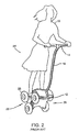
- FIG. 2 Another prior art balancing vehicle is shown in Fig. 2 and designated generally by numeral 24.
- Personal vehicle 24 shares the characteristics of vehicle 12 of Fig. 1, namely a support platform 12 for supporting subject 10 and grip 14 on handle 16 attached to platform 12, so that the vehicle 18 of this embodiment may also be operated in a manner analogous to a scooter.
- Fig. 2 shows that while vehicle 24 may have clusters 26 each having a plurality of wheels 28, vehicle 24 remains statically unstable and, absent operation of a control loop to maintain dynamic stability, subject 10 will no longer be supported in a standing position and will fall from platform 12.
- statically stable vehicles such as automobiles or the stair-climbing vehicle described in U.S. patent no. 4,790,548 (Decelles et al.).
- These statically stable vehicles lack a balancing capability. They also lack the capability for motion of the vehicle to be governed by leaning of the operator.
- a vehicle for transporting a human subject over a surface that may be irregular.
- the vehicle has a support platform for supporting the subject, with fore-aft and lateral planes defined by the orientation of the support platform.
- the vehicle has a ground-contacting module pivotably coupled to the support platform, for suspending the support platform over the surface, the support platform and the ground-contacting module being components of an assembly, and a motorized drive arrangement, mounted to the assembly, for causing locomotion of the assembly and the subject over the surface.
- the vehicle has a control loop, in which the motorized drive arrangement is included, for dynamically maintaining stability of the assembly by operation of the motorized drive arrangement in such a manner as to cause a specified acceleration of the assembly.
- the vehicle may also have a pivot for pivotal coupling of the support platform to the ground-contacting module and a locking mechanism for restricting motion of the support platform with respect to the ground-contacting module.
- the locking mechanism for restricting motion of the support platform may be activated upon interruption of power to the control loop.
- the ground-contacting module may include at least one wheel aft, and at least one wheel forward, of a vertical line through the center of gravity of the assembly under static conditions.
- the ground-contacting module may have a first wheel rotatable about a first axis and a second wheel rotatable about a second axis, the second axis being non-colinear with the first axis.
- control loop may be configured so that fore and aft motion of the vehicle is controlled by fore and aft leaning of the support platform as affected by the subject.
- Fig. 3 shows a simplified embodiment of a personal vehicle 100 having a drive platform 102 that is statically stable, at least on level ground 104.
- a drive platform 102 that is statically stable, at least on level ground 104.
- ground-contacting element 104 In addition to laterally disposed ground-contacting element 104 (only the right, or near, ground- contacting element is shown), one or more additional ground-contacting elements 106 are provided, additional ground-contacting element 106 having an axle 108 not coinciding with axle 110 of either of the other ground-contacting element.
- wheel is used in this application to refer to the ground-contacting elements of the vehicle, it is to be understood that this is without intent to limit the nature of the ground-contacting element that may be employed within the scope of the invention. It will be evident to persons of ordinary skill in the mechanical arts that clusters of wheels, arcuate members, tracks, or treads, to cite various examples, may be substituted for the wheels under appropriate conditions.
- Wheels 104 help to define a series of axes including the vertical axis Z-Z, a lateral axis Y-Y parallel to the axis coincident with axle 110 of wheel 104, and a fore- aft axis X-X perpendicular to the wheel axis.
- the plane defined by the vertical axis Z-Z and the lateral axis Y-Y will sometimes be referred to as the "lateral plane”, and the plane defined by the fore-aft axis X-X and the vertical axis Z-Z will sometimes be referred to as the "fore-aft plane”.
- Directions parallel to the axes X-X and Y-Y are called the fore-aft and lateral directions respectively.
- the distance between axle 108 and axle 110 establishes the wheel base of vehicle 100.
- the wheel base may range from zero to over ten times a representative size of each wheel, however the wheel base is preferably in the range of one-half to four times the size of wheel 104.
- the sizes of the wheels 104 and 106 may be equal in size as shown, or may be unequal in size.
- Drive platform 102 is pivotally connected to a support platform 112 that supports an occupant of the vehicle.
- the occupant of the vehicle may be positioned in any position on the support platform, for example, the occupant may stand on the support platform.
- a handle 114 coupled to support platform 112, may be provided, along with a grip 116 so that the vehicle 100 of this embodiment may be operated in a manner analogous to a scooter.
- a control loop may be provided so that leaning of the subject results in the application of torque to one or more of wheels 104 and 106 about respective axles 108 and 110, thereby causing an acceleration of the vehicle.
- support platform 112 may pivot freely about pivot 118 fixed with respect to drive platform 102.
- pivoting of support platform 112 with respect to drive platform 102 may be limited to the fore-aft plane containing the vertical and the direction of forward motion. Within the plane of motion, pivoting of the support platform may be limited by travel stops coupled to drive platform 102 or by compliant members such a s springs connecting drive platform 102 to support platform 112 at either or both of the fore and aft ends of the respective platforms.
- support platform 112 may actively be driven by a rotary actuator 124 such as a motor. Under control of a control loop (discussed in detail below), the vertical balance of support platform 112 is maintained by driving support platform 102 in the forward or backward direction.
- the force on each wheel may be measured using ground force sensors.
- the vehicle of this embodiment may be equipped with a foot- (or force-) actuated switch to activate the vehicle, in such a manner that the switch is closed so as to power the vehicle automatically when the subject stands on the support platform 112.
- the control loop may fail to operate, such as would occur if power were to fail.
- pivot 118 may be locked, thereby forming a rigid connection between drive platform 102 and support platform 112. Locking of pivot 118 prevents support platform 112 and the user supported by the platform from pivoting in the fore-aft direction.
- vector 120 which is the resultant of gravity and of the fore-aft acceleration vector acting on center of gravity 122 of the occupied vehicle 100 is over the wheel base of drive platform 102, the occupied vehicle is stable and will not tip over. If pivot 118 were not to lock under these circumstances, support platform 112 would be free to pivot forward or backward and, absent the compensating movement of drive platform 102 under the control of the control loop, support platform 112 and the supported subject would lose vertical stability abruptly.
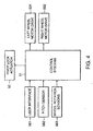
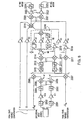
- a control system 51 for controlling motor drives and actuators in the embodiment of Fig. 3 to achieve locomotion and balance. These include motor drives 531 and 532 for left and right wheels respectively, and pivot lock actuator 52, which may be present in certain embodiments of the invention.
- the control system has data inputs including user interface 561, pitch sensor 562 for sensing fore-aft pitch, and wheel rotation sensors 563.
- Pitch sensor 562 may be a sensor for measuring the inertial pitch (i.e., an angle with respect to gravity) of the support platform, or, alternately, a sensor for measuring pivot, i.e., the angle between the support platform and the drive platform.
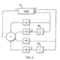
- FIG. 5 A simplified control algorithm for achieving balance in the embodiment of the invention according to Fig. 3 when the wheels are active for locomotion is shown in the block diagram of Fig. 5.
- Plant 61 is equivalent to the equations of motion of a system with a ground contacting module driven by a single motor, before the control loop is applied.
- the operation of control loops as depicted in Fig. 5 is well known in the art of electromechanical engineering, and is outlined, for example, in Fraser & Milne, Electro-Mechanical Engineering, IEEE Press (1994), particularly in Chapter 11, "Principles of Continuous Control," which is incorporated herein by reference.
- T identifies the wheel torque applied by a wheel drive to one or more of the wheels.
- the character identifies the fore-aft inclination (the pitch angle of the vehicle with respect to gravity, i.e., the vertical), X identifies the fore-aft displacement along the surface relative to the reference point, and the dot over a character denotes a variable differentiated with respect to time. Alternatively, may identify the angle of pivot or the difference in weight supported by from and rear wheels. The remaining portion of the figure is the control used to achieve balance.
- the boxes 62 and 63 indicate differentiation.
- the wheel torque T in this embodiment is set to satisfy the following equation:
- the gains K 1 , K 2 , K 3 , and K 4 are dependent upon the physical parameters of the system and other effects such as gravity, while offsets 0 and X 0 may be specified by the operating mode of the system, such as to limit the speed of the vehicle, or, alternatively, may be set by the user by means of a user input device.
- the torque desired from the left motor and the torque desired from the right motor can be calculated separately in the general manner described below in connection with Fig. 11. Additionally, tracking both the left wheel motion and the right wheel motion permits adjustments to be made to prevent unwanted turning of the vehicle and to account for performance variations between the two drive motors.
- a manual interface such as a joystick is used to adjust the torques of each motor.
- the joystick has axes indicated in Fig. 6.
- forward motions of the joystick is used to cause forward motion of the vehicle, and reverse motion of the joystick causes backward motion of the vehicle.
- a left turn similarly is accomplished by leftward motion of the joystick.
- the joystick is moved to the right.
- the configuration used here permits the vehicle to turn in place when the joystick is moved to the left or to the right.
- Fig. 7 is a block diagram providing detail of an implementation of a driver interface assembly designated generally by numeral 273.
- a peripheral microcomputer board 291 receives an input from joystick 292 as well as from inclinometer 293.
- the inclinometer provides information signals as to pitch and pitch rate.
- Peripheral micro controller board 291 also has inputs for receiving signals from a battery stack 271 as to battery voltage, battery current, and battery temperature.
- the peripheral micro controller board 291 is in communication over bus 279 with the central micro controller board 272.
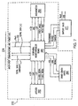
- Fig. 8 shows a control arrangement for the motors of the right and left drive wheels (corresponding to items 110 of Fig. 3).
- the arrangement has inputs of , r wl (linear velocity of the left wheel relative to the world coordinate system) and r wr (linear velocity of the right wheel), in addition to directional inputs 3300 determined by joystick position along X and Y axes of a reference coordinate system.
- Inputs , and error signals x and subject to gains K1, K2, K3, and K4 respectively, become inputs to summer 3319, which produces the basic balancing torque command for the wheels, in the general manner described above in connection with Fig. 5 above.
- the output of summer 3319 is combined with the output of yaw PID loop 3316 (described below) in summer 3320, then divided in divider 3322 and limited in saturation limiter 3324, to produce the left wheel torque command.
- the output of summer 3319 is combined with the output of PID loop 3316 in summer 3321, then divided in divider 3323 and limited in saturation limiter 3325, to produce the right wheel torque command.
- a directional input along the X axis moves the reference coordinate system along its X axis relative to the world coordinate system (which represents the traveled surface), at a velocity proportional to the displacement of the joystick.
- a directional input along the Y axis rotates the reference coordinate system about its Z axis at an angular velocity proportional to the displacement of the joystick.
- motion of the joystick in the positive X direction is here interpreted to mean forward motion; motion of the joystick in the negative X direction means reverse motion.
- motion of the joystick in the positive Y direction means leftward turning, counter-clockwise as viewed from above; motion of the joystick in the negative Y direction means rightward turning clockwise as viewed from above.
- the directional inputs Y and X are given deadband via deadband blocks 3301 and 3302 respectively, to widen the neutral position of the joystick, then subject to gains K11 and K10, then rate-limited by limiters 3303 and 3304 respectively, which limit the angular and linear accelerations respectively of the reference coordinate system.
- the sum of these outputs achieved through summer 3305 becomes the reference velocity r ref whereas the difference of these outputs achieved through summer 3306 becomes the reference velocity l ref .
- These reference velocities are subtracted in summers 3308 and 3307 from compensated linear velocity input signals r wl and r wr for left and right wheels (see description below in connection with Fig. 35 for these quantities) to obtain velocity error signals and, for left and right wheels within the reference coordinate system.
- Displacement error signal x is derived by integrating r wl and r wr in integrators 3310 and 3309, limiting the results in saturation limiters 3312 and 3311, and then averaging their outputs via summer 3313 and divider 3315. The difference between these displacements, determined via summer 3314, produces the yaw error signal 2.
- the yaw error signal 2 is run through a standard proportional-plus-integral- plus-derivative (PID) control loop 3316, the output of which is combined with the output of the basic balancing torque command of summer 3319, to produce the individual wheel torque commands, which cause the wheels to maintain fore-aft stability and also cause the vehicle to align itself with the axes of, and follow the origin of, the reference coordinate system as directed by directional input 3300.
- PID proportional-plus-integral- plus-derivative
Abstract
Description
- The present invention pertains to vehicles and methods for transporting individuals, and more particularly to vehicles and methods employing control loops in which a motorized drive is included.
- A wide range of vehicles and methods are known for transporting human subjects. Typically, such vehicles rely upon static stability, being designed so as to be stable under all foreseen conditions of placement of their ground-contacting members. Thus, for example, the gravity vector acting on the center of gravity of an automobile passes between the points of ground contact of the automobile's wheels, the suspension keeping all wheels on the ground at all times, and the automobile is thus stable. Alternatively, dynamic stability may be maintained by action of the user, as in the case of a bicycle, or, otherwise, by a control loop, as in the case of the human transporter described in U.S. patent no. 5,701,965 and U.S. patent application, serial no. 08/384,705, filed February 3,1995, which are herein incorporated by reference.
- The balancing vehicles described in these references, however, lack static stability. Referring, for example, to Fig. 1, wherein a prior art personal transporter is shown (see also US-A-5 971 091) and designated generally by
numeral 18, asubject 10 stands on asupport platform 12 and holds agrip 14 on ahandle 16 attached to theplatform 12, so that thevehicle 18 of this embodiment may be operated in a manner analogous to a scooter. A control loop may be provided so that leaning of the subject results in the application of torque towheel 20 aboutaxle 22 thereby causing an acceleration of the vehicle.Vehicle 18, however, is statically unstable, and, absent operation of the control loop to maintain dynamic stability,subject 10 will no longer be supported in a standing position and will fall fromplatform 12. Another prior art balancing vehicle is shown in Fig. 2 and designated generally bynumeral 24.Personal vehicle 24 shares the characteristics ofvehicle 12 of Fig. 1, namely asupport platform 12 for supportingsubject 10 andgrip 14 onhandle 16 attached toplatform 12, so that thevehicle 18 of this embodiment may also be operated in a manner analogous to a scooter. Fig. 2 shows that whilevehicle 24 may haveclusters 26 each having a plurality ofwheels 28,vehicle 24 remains statically unstable and, absent operation of a control loop to maintain dynamic stability,subject 10 will no longer be supported in a standing position and will fall fromplatform 12. - By way of contrast, other prior art vehicles may be statically stable, such as automobiles or the stair-climbing vehicle described in U.S. patent no. 4,790,548 (Decelles et al.). These statically stable vehicles, however, lack a balancing capability. They also lack the capability for motion of the vehicle to be governed by leaning of the operator.
- In the case of statically unstable balancing vehicles, considerations of operator safety require adoption of special stratagems, such as those described in copending applications, serial nos. ()9/184,488, 08/892,566, and 09/168,551, for the event of failure of certain system components.
- In accordance with preferred embodiments of the present invention, there is provided a vehicle for transporting a human subject over a surface that may be irregular. The vehicle has a support platform for supporting the subject, with fore-aft and lateral planes defined by the orientation of the support platform. Additionally, the vehicle has a ground-contacting module pivotably coupled to the support platform, for suspending the support platform over the surface, the support platform and the ground-contacting module being components of an assembly, and a motorized drive arrangement, mounted to the assembly, for causing locomotion of the assembly and the subject over the surface. Finally, the vehicle has a control loop, in which the motorized drive arrangement is included, for dynamically maintaining stability of the assembly by operation of the motorized drive arrangement in such a manner as to cause a specified acceleration of the assembly.
- In accordance with alternate embodiments of the invention, the vehicle may also have a pivot for pivotal coupling of the support platform to the ground-contacting module and a locking mechanism for restricting motion of the support platform with respect to the ground-contacting module. The locking mechanism for restricting motion of the support platform may be activated upon interruption of power to the control loop. The ground-contacting module may include at least one wheel aft, and at least one wheel forward, of a vertical line through the center of gravity of the assembly under static conditions. The ground-contacting module may have a first wheel rotatable about a first axis and a second wheel rotatable about a second axis, the second axis being non-colinear with the first axis.
- In accordance with further alternate embodiments of the invention, the control loop may be configured so that fore and aft motion of the vehicle is controlled by fore and aft leaning of the support platform as affected by the subject.
- The invention will be more readily understood by reference to the following description, taken with the accompanying drawings, in which:
- Fig. 1 is a side view of a prior art personal vehicle lacking a stable static position in which the subject remains in a standing position thereon;
- Fig. 2 is a perspective view of a second prior art personal vehicle also lacking a stable static position in which the subject remains in a standing position thereon;
- Fig. 3 is a side view of a personal vehicle having an independently suspended support platform in accordance with a preferred embodiment of the present invention;
- Fig. 4 is a block diagram showing generally the nature of sensors, power and control with the embodiment of Fig. 3;
- Fig. 5 illustrates the control strategy for a simplified version of Fig. 3 to achieve balance using wheel torque;
- Fig. 6 illustrates diagrammatically the operation of joystick control of the wheels of the embodiment of Fig. 3;
- Fig. 7 is a block diagram providing detail of a driver interface assembly; and
- Fig. 8 is a schematic of the wheel motor control during balancing and normal locomotion.
-
- Fig. 3 shows a simplified embodiment of a
personal vehicle 100 having adrive platform 102 that is statically stable, at least onlevel ground 104. In addition to laterally disposed ground-contacting element 104 (only the right, or near, ground- contacting element is shown), one or more additional ground-contactingelements 106 are provided, additional ground-contactingelement 106 having anaxle 108 not coinciding withaxle 110 of either of the other ground-contacting element. - While the term "wheel" is used in this application to refer to the ground-contacting elements of the vehicle, it is to be understood that this is without intent to limit the nature of the ground-contacting element that may be employed within the scope of the invention. It will be evident to persons of ordinary skill in the mechanical arts that clusters of wheels, arcuate members, tracks, or treads, to cite various examples, may be substituted for the wheels under appropriate conditions.
-
Wheels 104 help to define a series of axes including the vertical axis Z-Z, a lateral axis Y-Y parallel to the axis coincident withaxle 110 ofwheel 104, and a fore- aft axis X-X perpendicular to the wheel axis. The plane defined by the vertical axis Z-Z and the lateral axis Y-Y will sometimes be referred to as the "lateral plane", and the plane defined by the fore-aft axis X-X and the vertical axis Z-Z will sometimes be referred to as the "fore-aft plane". Directions parallel to the axes X-X and Y-Y are called the fore-aft and lateral directions respectively. - The distance between
axle 108 andaxle 110 establishes the wheel base ofvehicle 100. The wheel base may range from zero to over ten times a representative size of each wheel, however the wheel base is preferably in the range of one-half to four times the size ofwheel 104. The sizes of thewheels -
Drive platform 102 is pivotally connected to asupport platform 112 that supports an occupant of the vehicle. The occupant of the vehicle may be positioned in any position on the support platform, for example, the occupant may stand on the support platform. Ahandle 114, coupled to supportplatform 112, may be provided, along with agrip 116 so that thevehicle 100 of this embodiment may be operated in a manner analogous to a scooter. A control loop may be provided so that leaning of the subject results in the application of torque to one or more ofwheels respective axles - Under normal operating conditions,
support platform 112 may pivot freely aboutpivot 118 fixed with respect to driveplatform 102. In an alternate embodiment of the invention, pivoting ofsupport platform 112 with respect to driveplatform 102 may be limited to the fore-aft plane containing the vertical and the direction of forward motion. Within the plane of motion, pivoting of the support platform may be limited by travel stops coupled to driveplatform 102 or by compliant members such a s springs connectingdrive platform 102 to supportplatform 112 at either or both of the fore and aft ends of the respective platforms. In a further alternate embodiment of the invention,support platform 112 may actively be driven by arotary actuator 124 such as a motor. Under control of a control loop (discussed in detail below), the vertical balance ofsupport platform 112 is maintained bydriving support platform 102 in the forward or backward direction. -
Drive platform 102 may also respond to the commands of the user. User commands may be actuated, for example, by the operator shifting his or her weight forward or backward, or to one side or the other. In an embodiment wherein the support platform may pivot in a lateral direction, side lean by the operator may be used to determine the direction and rate of turning. Alternatively, the operator my actuate commands by means of a user input interface device, such as a joystick or dial attached, for example, to grip 116. Appropriate force transducers may be provided to sense leftward and rightward leaning and related controls provided to cause left and right turning as a result of the sensed leaning. The leaning may also be detected by measuring the pivot angle ofsupport platform 112. Additionally, the force on each wheel may be measured using ground force sensors. Similarly, the vehicle of this embodiment may be equipped with a foot- (or force-) actuated switch to activate the vehicle, in such a manner that the switch is closed so as to power the vehicle automatically when the subject stands on thesupport platform 112. - In an emergency condition, the control loop may fail to operate, such as would occur if power were to fail. When such a condition is detected,
pivot 118 may be locked, thereby forming a rigid connection betweendrive platform 102 andsupport platform 112. Locking ofpivot 118 preventssupport platform 112 and the user supported by the platform from pivoting in the fore-aft direction. As long as vector 120 (which is the resultant of gravity and of the fore-aft acceleration vector) acting on center ofgravity 122 of the occupiedvehicle 100 is over the wheel base ofdrive platform 102, the occupied vehicle is stable and will not tip over. Ifpivot 118 were not to lock under these circumstances,support platform 112 would be free to pivot forward or backward and, absent the compensating movement ofdrive platform 102 under the control of the control loop,support platform 112 and the supported subject would lose vertical stability abruptly. - While a
pivot 118 is shown forcoupling drive platform 102 andsupport platform 112, the use of any flexible linkage in place ofpivot 118 is within the scope of the present invention as described herein and as claimed in any appended claims. For example, in accordance with a further embodiment of the present invention, the flexible connection may coupledrive platform 102 to supportplatform 112 by means of springs or pneumatic pistons so as to provide a flexible coupling in normal powered operating mode and to urge theplatforms pivot 118. - In the block diagram of Fig. 4, a
control system 51 is shown for controlling motor drives and actuators in the embodiment of Fig. 3 to achieve locomotion and balance. These include motor drives 531 and 532 for left and right wheels respectively, andpivot lock actuator 52, which may be present in certain embodiments of the invention. The control system has data inputs includinguser interface 561,pitch sensor 562 for sensing fore-aft pitch, andwheel rotation sensors 563.Pitch sensor 562 may be a sensor for measuring the inertial pitch (i.e., an angle with respect to gravity) of the support platform, or, alternately, a sensor for measuring pivot, i.e., the angle between the support platform and the drive platform. - A simplified control algorithm for achieving balance in the embodiment of the invention according to Fig. 3 when the wheels are active for locomotion is shown in the block diagram of Fig. 5.
Plant 61 is equivalent to the equations of motion of a system with a ground contacting module driven by a single motor, before the control loop is applied. The operation of control loops as depicted in Fig. 5 is well known in the art of electromechanical engineering, and is outlined, for example, in Fraser & Milne, Electro-Mechanical Engineering, IEEE Press (1994), particularly in Chapter 11, "Principles of Continuous Control," which is incorporated herein by reference. In Fig. 5, T identifies the wheel torque applied by a wheel drive to one or more of the wheels. The characteridentifies the fore-aft inclination (the pitch angle of the vehicle with respect to gravity, i.e., the vertical), X identifies the fore-aft displacement along the surface relative to the reference point, and the dot over a character denotes a variable differentiated with respect to time. Alternatively,
boxes 62 and 63 indicate differentiation. To achieve dynamic control to insure stability of the system, and to keep the system in the neighborhood of a reference point on the surface, the wheel torque T in this embodiment is set to satisfy the following equation:The gains K1, K2, K3, and K4 are dependent upon the physical parameters of the system and other effects such as gravity, while offsets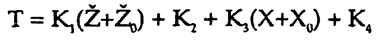
- In order to accommodate two driven wheels instead of the one-wheel system illustrated in Fig. 5, the torque desired from the left motor and the torque desired from the right motor can be calculated separately in the general manner described below in connection with Fig. 11. Additionally, tracking both the left wheel motion and the right wheel motion permits adjustments to be made to prevent unwanted turning of the vehicle and to account for performance variations between the two drive motors.
- A manual interface such as a joystick is used to adjust the torques of each motor. The joystick has axes indicated in Fig. 6. In operation of this embodiment, forward motions of the joystick is used to cause forward motion of the vehicle, and reverse motion of the joystick causes backward motion of the vehicle. A left turn similarly is accomplished by leftward motion of the joystick. For a right turn, the joystick is moved to the right. The configuration used here permits the vehicle to turn in place when the joystick is moved to the left or to the right. With respect to forward and reverse motion an alternative to the joystick is simply leaning forward or backward, since the pitch sensor (measuring
- It can be seen that the approach of adjusting motor torques permits fore-aft stability to be achieved. In other words, stability is achieved dynamically, by motion of the components of the vehicle (in this case constituting the entire vehicle) relative to the ground.
- Fig. 7 is a block diagram providing detail of an implementation of a driver interface assembly designated generally by
numeral 273. Aperipheral microcomputer board 291 receives an input fromjoystick 292 as well as frominclinometer 293. The inclinometer provides information signals as to pitch and pitch rate. (The term "inclinometer" as used in this context throughout this description and in the accompanying claims means any device, including accelerometers, pivot angle sensors, gyroscopes, ground force sensors, or any combination thereof, providing an output indicative of pitch or pitch rate, regardless of the arrangement used to achieve the output; if only one of the pitch and pitch rate variables is provided as an output, the other variable can be obtained by suitable differentiation or integration with respect to time.) To permit controlled banking into turns by the vehicle (thereby to increase stability while turning) it is also feasible to utilize a second inclinometer to provide information as to roll and roll rate or, alternatively, the resultant of system weight and centrifugal force.Other inputs 294 may also be desirably provided as an input to the peripheralmicro controller board 291. Such other inputs may include signals gated by switches (knobs and buttons) for chair adjustment, in embodiments where a chair is provided, and for determining specialized modes of operation. Peripheralmicro controller board 291 also has inputs for receiving signals from abattery stack 271 as to battery voltage, battery current, and battery temperature. The peripheralmicro controller board 291 is in communication overbus 279 with the central micro controller board 272. - Fig. 8 shows a control arrangement for the motors of the right and left drive wheels (corresponding to
items 110 of Fig. 3). The arrangement has inputs ofdirectional inputs 3300 determined by joystick position along X and Y axes of a reference coordinate system. Inputssummer 3319, which produces the basic balancing torque command for the wheels, in the general manner described above in connection with Fig. 5 above. The output ofsummer 3319 is combined with the output of yaw PID loop 3316 (described below) insummer 3320, then divided individer 3322 and limited insaturation limiter 3324, to produce the left wheel torque command. Similarly, the output ofsummer 3319 is combined with the output ofPID loop 3316 insummer 3321, then divided individer 3323 and limited insaturation limiter 3325, to produce the right wheel torque command. - In Fig. 8, a directional input along the X axis moves the reference coordinate system along its X axis relative to the world coordinate system (which represents the traveled surface), at a velocity proportional to the displacement of the joystick. A directional input along the Y axis rotates the reference coordinate system about its Z axis at an angular velocity proportional to the displacement of the joystick. It will be appreciated that motion of the joystick in the positive X direction is here interpreted to mean forward motion; motion of the joystick in the negative X direction means reverse motion. Similarly, motion of the joystick in the positive Y direction means leftward turning, counter-clockwise as viewed from above; motion of the joystick in the negative Y direction means rightward turning clockwise as viewed from above. Hence the directional inputs Y and X are given deadband via
deadband blocks limiters 3303 and 3304 respectively, which limit the angular and linear accelerations respectively of the reference coordinate system. The sum of these outputs achieved throughsummer 3305 becomes the reference velocity r ref whereas the difference of these outputs achieved through summer 3306 becomes the reference velocity l ref . These reference velocities are subtracted insummers summer 3317 anddivider 3318, produces a linear velocity error signal. Displacement error signal x is derived by integrating rwl and rwr inintegrators saturation limiters summer 3313 anddivider 3315. The difference between these displacements, determined viasummer 3314, produces the yaw error signal 2. - The yaw error signal 2 is run through a standard proportional-plus-integral- plus-derivative (PID)
control loop 3316, the output of which is combined with the output of the basic balancing torque command ofsummer 3319, to produce the individual wheel torque commands, which cause the wheels to maintain fore-aft stability and also cause the vehicle to align itself with the axes of, and follow the origin of, the reference coordinate system as directed bydirectional input 3300. - The described embodiments of the invention are intended to be merely exemplary and numerous variations and modifications will be apparent to those skilled in the art. All such variations and modifications are intended to be within the scope of the present invention as defined in the appended claims.
Claims (11)
- A vehicle, for transporting a human subject over a surface that may be irregular, the vehicle comprising:a. a support platform (112) for supporting the subject, the support platform defining fore-aft and lateral planes;b. a ground-contacting module (102, 104, 106) pivotably attached to the support platform for suspending the support platform over the surface, the ground-contacting module comprising a plurality of ground contacting elements having at least two non-coinciding axles and being stable to tipping both fore and aft while stationary;c. a motorized drive arrangement (531, 532), mounted to at least one of the ground contacting module (102, 104, 106) and the support platform (112), for causing locomotion of the ground contacting module over the surface; andd. a control loop, in which the motorized drive arrangement is included, for dynamically maintaining stability of the support platform (112) by operation of the motorized drive arrangement (531, 532) in such a manner as to cause a specified acceleration of the ground contacting module.
- A vehicle in accordance with claim 1, further comprising a pivot (118) for pivotal coupling of the support platform to the ground-contacting module.
- A vehicle in accordance with claim 1, further comprising a locking mechanism for restricting motion of the support platform with respect to the ground-contacting module.
- A vehicle in accordance with claim 3, wherein the locking mechanism for restricting motion of the support platform is activated upon interruption of power to the control loop.
- A vehicle in accordance with claim 1, further comprising an actuator for adjusting a pivot angle of the support platform with respect to the ground-contacting module.
- A vehicle in accordance with claim 2, wherein the ground-contacting module (102, 104, 106) includes at least one wheel (106) aft of a vertical line through the pivot (118) and at least one wheel (104) forward of the vertical line while on level ground.
- A vehicle in accordance with claim 1, wherein the ground-contacting module comprises:a. a first wheel rotatable about a first axis; andb. a second wheel rotatable about a second axis, the second axis being non-colinear with the first axis.
- A vehicle according to claim 1, wherein the control loop is configured so that fore and aft motion of the vehicle is controlled by fore and aft leaning of the support platform (112).
- A vehicle according to claim 1. further comprising a handle (116) mounted to the support platform.
- A vehicle according to claim 1, further including at least two ground reaction force sensors for generating a signal associated with leaning of the subject such that the control loop operates the motorized drive arrangement in response to the signal.
- A method for controlling a vehicle having a support platform (112) and a ground-contacting module (102, 104, 106) pivotably coupled to the support platform (112), the ground-contacting module stable to tipping both fore and aft while stationary, the vehicle further having a motorized drive assembly (531, 532) for causing locomotion of the vehicle, the support platform (112) having an operating position that is unstable with respect to tipping in a fore-aft plane, the method comprising:a. measuring a pivot angle of the support platform (112) with respect to the ground-contacting module (102, 104, 106); andb. governing the motorized drive arrangement (531, 532) on the basis at least of the pivot angle of the support platform in such a manner as to cause a specified acceleration of the vehicle.
Applications Claiming Priority (3)
| Application Number | Priority Date | Filing Date | Title |
|---|---|---|---|
| US456347 | 1999-12-08 | ||
| US09/456,347 US6543564B1 (en) | 1994-05-27 | 1999-12-08 | Balancing personal vehicle |
| PCT/US2000/042698 WO2001042077A2 (en) | 1999-12-08 | 2000-12-08 | Balancing personal vehicle |
Publications (2)
| Publication Number | Publication Date |
|---|---|
| EP1237779A2 EP1237779A2 (en) | 2002-09-11 |
| EP1237779B1 true EP1237779B1 (en) | 2005-07-20 |
Family
ID=23812398
Family Applications (1)
| Application Number | Title | Priority Date | Filing Date |
|---|---|---|---|
| EP00992888A Expired - Lifetime EP1237779B1 (en) | 1999-12-08 | 2000-12-08 | Balancing personal vehicle |
Country Status (10)
| Country | Link |
|---|---|
| US (2) | US6543564B1 (en) |
| EP (1) | EP1237779B1 (en) |
| JP (1) | JP5366285B2 (en) |
| KR (1) | KR100704800B1 (en) |
| AT (1) | ATE299826T1 (en) |
| AU (1) | AU4715001A (en) |
| CA (1) | CA2393418C (en) |
| DE (1) | DE60021419T2 (en) |
| MX (1) | MXPA02005801A (en) |
| WO (1) | WO2001042077A2 (en) |
Families Citing this family (91)
| Publication number | Priority date | Publication date | Assignee | Title |
|---|---|---|---|---|
| US6868931B2 (en) * | 1994-05-27 | 2005-03-22 | Deka Products Limited Partnership | Speed limiting for a balancing transporter accounting for variations in system capability |
| US6543564B1 (en) * | 1994-05-27 | 2003-04-08 | Deka Products Limited Partnership | Balancing personal vehicle |
| US6799649B2 (en) * | 1999-03-15 | 2004-10-05 | Deka Products Limited Partnership | Control of a balancing personal vehicle |
| US7740099B2 (en) | 1999-06-04 | 2010-06-22 | Segway Inc. | Enhanced control of a transporter |
| US7275607B2 (en) | 1999-06-04 | 2007-10-02 | Deka Products Limited Partnership | Control of a personal transporter based on user position |
| US6554086B1 (en) * | 2000-10-27 | 2003-04-29 | Invacare Corporation | Obstacle traversing wheelchair |
| US7040429B2 (en) | 2001-10-10 | 2006-05-09 | Invacare Corporation | Wheelchair suspension |
| US7066290B2 (en) * | 2001-10-19 | 2006-06-27 | Invacare Corp. | Wheelchair suspension having pivotal motor mount |
| US7017686B2 (en) * | 2002-06-11 | 2006-03-28 | Deka Products Limited Partnership | Hybrid human/electric powered vehicle |
| WO2004007264A1 (en) | 2002-07-12 | 2004-01-22 | Deka Products Limited Partnership | Control of a transporter based on attitude |
| US6851711B2 (en) * | 2002-08-16 | 2005-02-08 | Invacare Corporation | Vehicle having an anti-dive/lockout mechanism |
| US11213441B2 (en) | 2002-10-25 | 2022-01-04 | Invacare Corporation | Suspension for wheeled vehicles |
| US7293801B2 (en) * | 2003-08-18 | 2007-11-13 | Invacare Corporation | Self-stabilizing suspension for wheeled vehicles |
| US7083195B2 (en) * | 2002-10-25 | 2006-08-01 | Invacare Corporation | Suspension with releasable locking system |
| JP4523244B2 (en) * | 2003-05-22 | 2010-08-11 | 独立行政法人科学技術振興機構 | Power-assisted mobile trolley |
| JP4411867B2 (en) * | 2003-06-04 | 2010-02-10 | トヨタ自動車株式会社 | Vehicles that can be steered by moving the center of gravity |
| JP4576825B2 (en) * | 2003-06-10 | 2010-11-10 | 株式会社安川電機 | Electric scooter drive control device and electric scooter including the same |
| WO2004110854A1 (en) * | 2003-06-12 | 2004-12-23 | Sony Corporation | Coaxial motorcycle |
| US6907949B1 (en) * | 2003-08-22 | 2005-06-21 | John Baron Wang | Battery powered motor vehicle and method of use |
| JP3981733B2 (en) * | 2003-09-17 | 2007-09-26 | 独立行政法人産業技術総合研究所 | Parallel two-wheel passenger cart |
| EP1529556B1 (en) * | 2003-11-04 | 2013-02-20 | Toyota Jidosha Kabushiki Kaisha | Travelling apparatus and method for controlling thereof |
| JP4556418B2 (en) * | 2003-11-04 | 2010-10-06 | トヨタ自動車株式会社 | Traveling apparatus and control method thereof |
| JP4442319B2 (en) * | 2004-05-25 | 2010-03-31 | トヨタ自動車株式会社 | Traveling device |
| JP2006076699A (en) * | 2004-09-08 | 2006-03-23 | Daifuku Co Ltd | Article carrying vehicle |
| JP4734666B2 (en) * | 2005-03-16 | 2011-07-27 | 独立行政法人産業技術総合研究所 | 3-wheeled passenger car |
| US7744331B2 (en) * | 2006-01-26 | 2010-06-29 | Xerox Corporation | Transport vehicle and method |
| JP4291822B2 (en) * | 2006-02-03 | 2009-07-08 | トヨタ自動車株式会社 | Inverted wheel type traveling body |
| US20100032911A1 (en) * | 2006-03-06 | 2010-02-11 | Sterraclimb Llc | Stair-Climbing Wheeled Vehicle |
| KR100789906B1 (en) * | 2006-05-03 | 2008-01-02 | 안 데이비드 | Personal transport vehicle |
| EP2017172A4 (en) * | 2006-05-09 | 2011-11-02 | Equos Res Co Ltd | Vehicle, characteristic value estimating device, and loaded article determination device |
| US7979179B2 (en) * | 2006-08-11 | 2011-07-12 | Segway Inc. | Apparatus and method for pitch state estimation for a vehicle |
| CN101501598A (en) | 2006-08-11 | 2009-08-05 | 塞格威股份有限公司 | Speed limiting in electric vehicles |
| US7847504B2 (en) * | 2006-10-10 | 2010-12-07 | Carnegie Mellon University | Dynamic balancing mobile robot |
| US7798264B2 (en) * | 2006-11-02 | 2010-09-21 | Hutcheson Timothy L | Reconfigurable balancing robot and method for dynamically transitioning between statically stable mode and dynamically balanced mode |
| US7938299B2 (en) * | 2006-11-03 | 2011-05-10 | S.C. Johnson & Son, Inc. | Device for attaching a dip tube to a fluid container |
| EP1943995A1 (en) * | 2007-01-12 | 2008-07-16 | Invacare International Sàrl | A wheeled conveyance with suspension arms for wheels |
| US8272461B2 (en) | 2007-02-08 | 2012-09-25 | Invacare Corporation | Wheelchair suspension |
| EP2114749A4 (en) * | 2007-02-12 | 2010-07-07 | Sterraclimb Llc | Stair-climbing wheeled vehicle |
| CA2676724C (en) * | 2007-02-14 | 2013-12-17 | Invacare Corporation | Stability control system |
| NL1033676C2 (en) * | 2007-04-12 | 2008-10-14 | Nedap Nv | Scooter, has driven ball and dynamically controlled lateral stability for balancing scooter in any direction |
| US7669862B2 (en) * | 2007-04-27 | 2010-03-02 | Sterraclimb Llc | Foldable spider wheel for ascending and descending stairs |
| US20090055033A1 (en) * | 2007-08-23 | 2009-02-26 | Segway Inc. | Apparatus and methods for fault detection at vehicle startup |
| JP4825856B2 (en) * | 2008-09-12 | 2011-11-30 | トヨタ自動車株式会社 | Mobile body and control method thereof |
| WO2010029669A1 (en) * | 2008-09-11 | 2010-03-18 | トヨタ自動車株式会社 | Moving body and control method thereof |
| JP5263058B2 (en) * | 2009-07-29 | 2013-08-14 | トヨタ自動車株式会社 | Boarding posture holding mechanism and coaxial motorcycle |
| JP5276719B2 (en) * | 2009-09-18 | 2013-08-28 | 本田技研工業株式会社 | Inverted pendulum type moving body |
| WO2011033581A1 (en) * | 2009-09-18 | 2011-03-24 | 本田技研工業株式会社 | Inverted pendulum-type vehicle controller |
| EP3238682A3 (en) | 2009-10-09 | 2018-01-10 | Invacare Corporation | Wheelchair suspension with opposite movement of anti-tip arms |
| EP2357125A1 (en) * | 2010-02-17 | 2011-08-17 | Zouce AB | Vehicle having a level compensation system |
| US20110204592A1 (en) * | 2010-02-17 | 2011-08-25 | Johansen N Layne | Mobility and Accessibility Device and Lift |
| WO2011111123A1 (en) | 2010-03-12 | 2011-09-15 | トヨタ自動車株式会社 | Mobile object |
| US9504909B2 (en) * | 2011-05-05 | 2016-11-29 | Qualcomm Incorporated | Method and apparatus of proximity and stunt recording for outdoor gaming |
| US8403095B1 (en) * | 2011-12-05 | 2013-03-26 | Bryce A. Ecklein | Step on-step off motorized utility vehicle |
| US9585801B2 (en) * | 2012-02-09 | 2017-03-07 | Ogo Technology Limited | Powered mobility device |
| WO2013123398A1 (en) | 2012-02-15 | 2013-08-22 | Invacare Corporation | Wheelchair suspension |
| US9526977B2 (en) | 2012-03-29 | 2016-12-27 | Daniel B. Edney | Powered skate with automatic motor control |
| US9235241B2 (en) | 2012-07-29 | 2016-01-12 | Qualcomm Incorporated | Anatomical gestures detection system using radio signals |
| US9114844B2 (en) | 2012-10-03 | 2015-08-25 | Hauler Cycles, LLC | Bicycle conversion kit and tricycle apparatus |
| WO2014115265A1 (en) * | 2013-01-23 | 2014-07-31 | Sato Kuniaki | Mobile device for single rider |
| WO2015009369A1 (en) * | 2013-07-17 | 2015-01-22 | C. Johnson Industries, Llc | Multi-wheel single operator transport platform |
| US9682732B2 (en) | 2013-09-06 | 2017-06-20 | Jason Thomas Strack | Fully self-balanced hands-free portable vehicle |
| US9643077B2 (en) * | 2013-10-21 | 2017-05-09 | Equalia LLC | Pitch-propelled vehicle |
| US10369453B2 (en) | 2013-10-21 | 2019-08-06 | Equalia LLC | Pitch-propelled vehicle |
| US9211470B2 (en) | 2013-10-21 | 2015-12-15 | Equalia LLC. | Pitch-propelled vehicle |
| WO2016079614A1 (en) * | 2014-11-18 | 2016-05-26 | Zehus S.R.L. | System for controlling the motion of an impulsive-type human-powered vehicle |
| CN205150090U (en) * | 2015-10-26 | 2016-04-13 | 周深根 | Car is felt to four -wheel body |
| WO2017077362A1 (en) | 2015-11-03 | 2017-05-11 | Koofy Development Limited | Self balancing single wheel board with shock absorber |
| WO2017081523A1 (en) | 2015-11-15 | 2017-05-18 | Koofy Development Limited | Self-balancing single wheel board with anti-fall and brake safety systems |
| USD797875S1 (en) | 2016-01-19 | 2017-09-19 | Koofy Development Limited | Skateboard |
| US10908045B2 (en) | 2016-02-23 | 2021-02-02 | Deka Products Limited Partnership | Mobility device |
| PT3420417T (en) | 2016-02-23 | 2023-05-04 | Deka Products Lp | Mobility device control system |
| US10926756B2 (en) | 2016-02-23 | 2021-02-23 | Deka Products Limited Partnership | Mobility device |
| US11399995B2 (en) | 2016-02-23 | 2022-08-02 | Deka Products Limited Partnership | Mobility device |
| USD827747S1 (en) | 2016-03-14 | 2018-09-04 | Koofy Innovation Limited | Skateboard |
| JP6916812B2 (en) | 2016-04-14 | 2021-08-11 | デカ・プロダクツ・リミテッド・パートナーシップ | User control device for transporter |
| US10525784B2 (en) * | 2016-06-29 | 2020-01-07 | Upnride Robotics Ltd. | Self-leveling mechanism and method for wheeled mobility device |
| USD807457S1 (en) | 2016-07-20 | 2018-01-09 | Razor Usa Llc | Two wheeled board |
| USD840872S1 (en) | 2016-07-20 | 2019-02-19 | Razor Usa Llc | Two wheeled board |
| USD837323S1 (en) | 2018-01-03 | 2019-01-01 | Razor Usa Llc | Two wheeled board |
| USD941948S1 (en) | 2016-07-20 | 2022-01-25 | Razor Usa Llc | Two wheeled board |
| USD803963S1 (en) | 2016-07-20 | 2017-11-28 | Razor Usa Llc | Two wheeled board |
| US10772774B2 (en) | 2016-08-10 | 2020-09-15 | Max Mobility, Llc | Self-balancing wheelchair |
| USD829612S1 (en) | 2017-05-20 | 2018-10-02 | Deka Products Limited Partnership | Set of toggles |
| USD846452S1 (en) | 2017-05-20 | 2019-04-23 | Deka Products Limited Partnership | Display housing |
| EP3658096B1 (en) | 2017-07-25 | 2021-07-07 | Christoph Sauer | Self-balancing, single-axle running-gear unit having a stair-climbing function |
| US11524740B2 (en) | 2017-08-05 | 2022-12-13 | Shane Chen | Transportation device having multiple axes of rotation and auto-balance based drive control |
| KR102002902B1 (en) * | 2017-10-13 | 2019-07-24 | 네이버랩스 주식회사 | Personal mobility |
| GB2569657A (en) * | 2017-12-22 | 2019-06-26 | Uniwheel Ltd | Load balancing transportation device |
| CN209553392U (en) | 2017-12-22 | 2019-10-29 | 美国锐哲有限公司 | Electrodynamic balance vehicle |
| JP2021527204A (en) | 2018-06-07 | 2021-10-11 | デカ・プロダクツ・リミテッド・パートナーシップ | Systems and methods for delivery multipurpose service execution |
| AU2021228590A1 (en) | 2020-02-25 | 2022-09-22 | Invacare Corporation | Wheelchair and suspension systems |
Family Cites Families (62)
| Publication number | Priority date | Publication date | Assignee | Title |
|---|---|---|---|---|
| FR980237A (en) | 1949-02-07 | 1951-05-09 | Baby carriage or crawler stroller | |
| GB719048A (en) | 1952-02-01 | 1954-11-24 | Karl Adolf Hartmann | Improvements in and relating to invalid chairs or like vehicles |
| US3145797A (en) | 1960-09-21 | 1964-08-25 | Charles F Taylor | Vehicle |
| US3260324A (en) | 1963-11-12 | 1966-07-12 | Caesar R Suarez | Motorized unicycle |
| US3288234A (en) | 1964-08-17 | 1966-11-29 | Jack M Feliz | Stair climbing conveyance |
| CA820683A (en) | 1965-10-13 | 1969-08-19 | P. Forsyth John | Vehicle |
| US3374845A (en) | 1966-05-05 | 1968-03-26 | Selwyn Donald | Command control system for vehicles |
| US3399742A (en) | 1966-06-23 | 1968-09-03 | Franklin S. Malick | Powered unicycle |
| US3580344A (en) | 1968-12-24 | 1971-05-25 | Johnnie E Floyd | Stair-negotiating wheel chair or an irregular-terrain-negotiating vehicle |
| GB1213930A (en) | 1969-05-29 | 1970-11-25 | John Fay Fleming | A vehicle for climbing stairs |
| JPS5638676B2 (en) | 1973-08-27 | 1981-09-08 | ||
| JPS5244933A (en) | 1975-10-03 | 1977-04-08 | Kouji Shimizu | Wheeled chair |
| US4020914A (en) | 1976-02-23 | 1977-05-03 | Wolfgang Trautwein | Stabilized three-wheeled vehicle |
| US4088199A (en) | 1976-02-23 | 1978-05-09 | Wolfgang Trautwein | Stabilized three-wheeled vehicle |
| BE841212A (en) * | 1976-04-28 | 1976-08-16 | SPORTS VEHICLE | |
| SE410838B (en) | 1976-10-22 | 1979-11-12 | Mo Och Domsjoe Ab | DEVICE TO REDUCE THE SLOPE OF A VEHICLE CONSTRUCTION |
| US4109741A (en) | 1977-07-29 | 1978-08-29 | Gabriel Charles L | Motorized unicycle wheel |
| US4222449A (en) | 1978-06-08 | 1980-09-16 | Feliz Jack M | Step-climbing wheel chair |
| DE2915387A1 (en) | 1979-04-14 | 1980-10-16 | Heinz Eichholz | ELECTRIC VEHICLE |
| JPS5787766A (en) | 1980-11-19 | 1982-06-01 | Waseda Daigaku | Monocycle |
| FR2502090A1 (en) | 1981-03-17 | 1982-09-24 | Tobex Motivated Chair Cy Ltd | VEHICLE FOR GOING UP AND DOWN FROM STAIRS |
| DE3128112A1 (en) | 1981-07-16 | 1983-02-03 | Gerhard Dipl.-Ing. 6100 Darmstadt Heid | Small electric vehicle |
| US4375840A (en) | 1981-09-23 | 1983-03-08 | Campbell Jack L | Mobile support |
| US4566707A (en) | 1981-11-05 | 1986-01-28 | Nitzberg Leonard R | Wheel chair |
| IT8105071V0 (en) | 1981-11-20 | 1981-11-20 | Tgr Srl | ELECTRIC TRACTION TROLLEY, PARTICULARLY SUITABLE FOR TRANSPORTING WEIGHTS EVEN CONSIDERABLE AND VOLUMINOUS, ALONG THE BUILDING STAIRS |
| CH658831A5 (en) | 1982-10-19 | 1986-12-15 | Rohr Martin Von | STAIRCASE AND THRESHOLD IMPELLER. |
| GB2139576A (en) | 1983-05-13 | 1984-11-14 | Mavispace Ltd | Stair climbing devices |
| DE3334093A1 (en) * | 1983-09-21 | 1985-04-11 | Robert Bosch Gmbh, 7000 Stuttgart | METHOD AND CIRCUIT FOR DETERMINING THE OPTIMUM OPERATIONAL GEARBOX OF A MOTOR VEHICLE DRIVE |
| JPS60255580A (en) | 1984-05-31 | 1985-12-17 | Hitoshi Takahashi | Walking robot |
| JPS615415A (en) | 1984-06-19 | 1986-01-11 | Matsushita Electric Ind Co Ltd | Magnetic head |
| FR2576863A1 (en) | 1985-01-31 | 1986-08-08 | Brunet Pierre | MOTORIZED DISPLACEMENT DEVICE, FOR EXAMPLE FOR RUNNING AND DESCENDING STAIRS |
| GB8515992D0 (en) | 1985-06-25 | 1985-07-31 | Hester R | Wheelchair |
| US4657272A (en) | 1985-09-11 | 1987-04-14 | Davenport James M | Wheeled vehicle |
| US4624469A (en) | 1985-12-19 | 1986-11-25 | Bourne Jr Maurice W | Three-wheeled vehicle with controlled wheel and body lean |
| US4791902A (en) * | 1986-07-16 | 1988-12-20 | Honda Giken Kogyo Kabushiki Kaisha | Throttle valve control system for an internal combustion engine |
| GB8618044D0 (en) | 1986-07-24 | 1986-09-03 | Sheeter E | Vehicle |
| US4802542A (en) | 1986-08-25 | 1989-02-07 | Falcon Rehabilitation Products, Inc. | Powered walker |
| US4809804A (en) | 1986-08-25 | 1989-03-07 | Falcon Rehabilitation Products, Inc. | Combination wheelchair and walker apparatus |
| CA1275296C (en) | 1987-05-04 | 1990-10-16 | Pierre Decelles | Climbing and descending vehicle |
| JP2530652B2 (en) | 1987-06-05 | 1996-09-04 | シ−ケ−ディ株式会社 | Attitude control method for coaxial two-wheeled vehicles |
| US4874055A (en) | 1987-12-16 | 1989-10-17 | Beer Robin F C | Chariot type golf cart |
| DE3800476A1 (en) | 1988-01-11 | 1989-07-20 | Anschuetz & Co Gmbh | METHOD FOR STABILIZING A UNI-AXLE CYCLING VEHICLE AND VEHICLE STABILIZED BY THIS METHOD |
| JP2695892B2 (en) | 1989-01-19 | 1998-01-14 | 豊田工機株式会社 | Fall prevention device for self-propelled robot |
| US4998596A (en) | 1989-05-03 | 1991-03-12 | Ufi, Inc. | Self-propelled balancing three-wheeled vehicle |
| CH681353A5 (en) | 1989-05-17 | 1993-03-15 | Aluweld Sa | |
| US5248007A (en) | 1989-11-21 | 1993-09-28 | Quest Technologies, Inc. | Electronic control system for stair climbing vehicle |
| JP3070015B2 (en) * | 1990-11-30 | 2000-07-24 | 本田技研工業株式会社 | Travel control system for unstable vehicles |
| IT1253213B (en) | 1991-10-18 | 1995-07-11 | Tgr Srl | TRACKED, ARTICULATED VEHICLE, ALSO PREPARED FOR WHEEL DRIVING, SUITABLE TO TACKLE ANY TYPE OF ROUTE IN AN INDEPENDENT AND SAFE FORM, INCLUDING THE ASCENT AND DESCENT OF STAIRS, ESPECIALLY SUITABLE FOR DISABLED WHEELCHAIRS |
| US5314034A (en) | 1991-11-14 | 1994-05-24 | Chittal Nandan R | Powered monocycle |
| JPH06105415A (en) | 1992-09-18 | 1994-04-15 | Mitsubishi Electric Corp | Door handle device of switchboard |
| US5366036A (en) | 1993-01-21 | 1994-11-22 | Perry Dale E | Power stand-up and reclining wheelchair |
| US5975225A (en) * | 1993-02-24 | 1999-11-02 | Deka Products Limited Partnership | Transportation vehicles with stability enhancement using CG modification |
| US5701965A (en) | 1993-02-24 | 1997-12-30 | Deka Products Limited Partnership | Human transporter |
| US5971091A (en) | 1993-02-24 | 1999-10-26 | Deka Products Limited Partnership | Transportation vehicles and methods |
| US5350033A (en) | 1993-04-26 | 1994-09-27 | Kraft Brett W | Robotic inspection vehicle |
| US5441298A (en) * | 1993-10-22 | 1995-08-15 | Ford Motor Company | Apparatus for stabilizing an electric active suspension system upon interruption of the power supply |
| IT1273260B (en) | 1994-03-21 | 1997-07-07 | Tgr Srl | TRACKED VEHICLE, SUITABLE FOR ADDRESSING ANY TYPE OF ROUTE, INCLUDING THE ASCENT AND DESCENT OF STAIRS AND PARTICULARLY SUITABLE FOR THE CONSTRUCTION OF WHEELCHAIRS FOR INVALID |
| US6543564B1 (en) * | 1994-05-27 | 2003-04-08 | Deka Products Limited Partnership | Balancing personal vehicle |
| DK0806929T3 (en) | 1995-02-03 | 2005-03-14 | Deka Products Lp | Vehicles and methods of transport |
| US6003624A (en) | 1995-06-06 | 1999-12-21 | University Of Washington | Stabilizing wheeled passenger carrier capable of traversing stairs |
| US6068280A (en) * | 1996-09-13 | 2000-05-30 | Torres; Hank G. | Self-leveling seat for a wheelchair |
| US5921338A (en) * | 1997-08-11 | 1999-07-13 | Robin L. Edmondson | Personal transporter having multiple independent wheel drive |
-
1999
- 1999-12-08 US US09/456,347 patent/US6543564B1/en not_active Expired - Fee Related
-
2000
- 2000-12-08 KR KR1020027007338A patent/KR100704800B1/en not_active IP Right Cessation
- 2000-12-08 CA CA2393418A patent/CA2393418C/en not_active Expired - Lifetime
- 2000-12-08 JP JP2001543388A patent/JP5366285B2/en not_active Expired - Lifetime
- 2000-12-08 AT AT00992888T patent/ATE299826T1/en not_active IP Right Cessation
- 2000-12-08 MX MXPA02005801A patent/MXPA02005801A/en active IP Right Grant
- 2000-12-08 DE DE60021419T patent/DE60021419T2/en not_active Expired - Lifetime
- 2000-12-08 AU AU47150/01A patent/AU4715001A/en not_active Abandoned
- 2000-12-08 EP EP00992888A patent/EP1237779B1/en not_active Expired - Lifetime
- 2000-12-08 WO PCT/US2000/042698 patent/WO2001042077A2/en active IP Right Grant
-
2003
- 2003-02-26 US US10/374,689 patent/US6929080B2/en not_active Expired - Fee Related
Also Published As
| Publication number | Publication date |
|---|---|
| WO2001042077A2 (en) | 2001-06-14 |
| ATE299826T1 (en) | 2005-08-15 |
| KR100704800B1 (en) | 2007-04-10 |
| CA2393418A1 (en) | 2001-06-14 |
| EP1237779A2 (en) | 2002-09-11 |
| DE60021419D1 (en) | 2005-08-25 |
| JP2004500271A (en) | 2004-01-08 |
| US6929080B2 (en) | 2005-08-16 |
| MXPA02005801A (en) | 2003-02-27 |
| CA2393418C (en) | 2010-02-16 |
| US20030183435A1 (en) | 2003-10-02 |
| WO2001042077A3 (en) | 2002-03-14 |
| DE60021419T2 (en) | 2006-04-27 |
| US6543564B1 (en) | 2003-04-08 |
| KR20020067915A (en) | 2002-08-24 |
| JP5366285B2 (en) | 2013-12-11 |
| AU4715001A (en) | 2001-06-18 |
Similar Documents
| Publication | Publication Date | Title |
|---|---|---|
| EP1237779B1 (en) | Balancing personal vehicle | |
| US7023330B2 (en) | Transporter oscillating alarm | |
| US7017686B2 (en) | Hybrid human/electric powered vehicle | |
| US6827163B2 (en) | Non-linear control of a balancing vehicle | |
| US7090040B2 (en) | Motion control of a transporter | |
| US7174976B2 (en) | Dynamically stable transporter controlled by lean | |
| US20010006125A1 (en) | Motorized wheelchairs | |
| US20050126832A1 (en) | Non-linear control of a balancing vehicle | |
| AU2004200265B2 (en) | Personal mobility vehicles and methods |
Legal Events
| Date | Code | Title | Description |
|---|---|---|---|
| PUAI | Public reference made under article 153(3) epc to a published international application that has entered the european phase |
Free format text: ORIGINAL CODE: 0009012 |
|
| AK | Designated contracting states |
Kind code of ref document: A2 Designated state(s): AT BE CH CY DE DK ES FI FR GB GR IE IT LI LU MC NL PT SE TR |
|
| AX | Request for extension of the european patent |
Free format text: AL;LT;LV;MK;RO;SI |
|
| 17P | Request for examination filed |
Effective date: 20020705 |
|
| 17Q | First examination report despatched |
Effective date: 20040730 |
|
| GRAP | Despatch of communication of intention to grant a patent |
Free format text: ORIGINAL CODE: EPIDOSNIGR1 |
|
| GRAS | Grant fee paid |
Free format text: ORIGINAL CODE: EPIDOSNIGR3 |
|
| GRAA | (expected) grant |
Free format text: ORIGINAL CODE: 0009210 |
|
| AK | Designated contracting states |
Kind code of ref document: B1 Designated state(s): AT BE CH CY DE DK ES FI FR GB GR IE IT LI LU MC NL PT SE TR |
|
| PG25 | Lapsed in a contracting state [announced via postgrant information from national office to epo] |
Ref country code: IT Free format text: LAPSE BECAUSE OF FAILURE TO SUBMIT A TRANSLATION OF THE DESCRIPTION OR TO PAY THE FEE WITHIN THE PRESCRIBED TIME-LIMIT;WARNING: LAPSES OF ITALIAN PATENTS WITH EFFECTIVE DATE BEFORE 2007 MAY HAVE OCCURRED AT ANY TIME BEFORE 2007. THE CORRECT EFFECTIVE DATE MAY BE DIFFERENT FROM THE ONE RECORDED. Effective date: 20050720 Ref country code: AT Free format text: LAPSE BECAUSE OF FAILURE TO SUBMIT A TRANSLATION OF THE DESCRIPTION OR TO PAY THE FEE WITHIN THE PRESCRIBED TIME-LIMIT Effective date: 20050720 Ref country code: CH Free format text: LAPSE BECAUSE OF FAILURE TO SUBMIT A TRANSLATION OF THE DESCRIPTION OR TO PAY THE FEE WITHIN THE PRESCRIBED TIME-LIMIT Effective date: 20050720 Ref country code: BE Free format text: LAPSE BECAUSE OF FAILURE TO SUBMIT A TRANSLATION OF THE DESCRIPTION OR TO PAY THE FEE WITHIN THE PRESCRIBED TIME-LIMIT Effective date: 20050720 Ref country code: TR Free format text: LAPSE BECAUSE OF FAILURE TO SUBMIT A TRANSLATION OF THE DESCRIPTION OR TO PAY THE FEE WITHIN THE PRESCRIBED TIME-LIMIT Effective date: 20050720 Ref country code: LI Free format text: LAPSE BECAUSE OF FAILURE TO SUBMIT A TRANSLATION OF THE DESCRIPTION OR TO PAY THE FEE WITHIN THE PRESCRIBED TIME-LIMIT Effective date: 20050720 Ref country code: ES Free format text: LAPSE BECAUSE OF FAILURE TO SUBMIT A TRANSLATION OF THE DESCRIPTION OR TO PAY THE FEE WITHIN THE PRESCRIBED TIME-LIMIT Effective date: 20050720 Ref country code: NL Free format text: LAPSE BECAUSE OF FAILURE TO SUBMIT A TRANSLATION OF THE DESCRIPTION OR TO PAY THE FEE WITHIN THE PRESCRIBED TIME-LIMIT Effective date: 20050720 Ref country code: FI Free format text: LAPSE BECAUSE OF FAILURE TO SUBMIT A TRANSLATION OF THE DESCRIPTION OR TO PAY THE FEE WITHIN THE PRESCRIBED TIME-LIMIT Effective date: 20050720 |
|
| REG | Reference to a national code |
Ref country code: GB Ref legal event code: FG4D |
|
| REG | Reference to a national code |
Ref country code: CH Ref legal event code: EP |
|
| REG | Reference to a national code |
Ref country code: IE Ref legal event code: FG4D |
|
| REF | Corresponds to: |
Ref document number: 60021419 Country of ref document: DE Date of ref document: 20050825 Kind code of ref document: P |
|
| PG25 | Lapsed in a contracting state [announced via postgrant information from national office to epo] |
Ref country code: GR Free format text: LAPSE BECAUSE OF FAILURE TO SUBMIT A TRANSLATION OF THE DESCRIPTION OR TO PAY THE FEE WITHIN THE PRESCRIBED TIME-LIMIT Effective date: 20051020 Ref country code: DK Free format text: LAPSE BECAUSE OF FAILURE TO SUBMIT A TRANSLATION OF THE DESCRIPTION OR TO PAY THE FEE WITHIN THE PRESCRIBED TIME-LIMIT Effective date: 20051020 Ref country code: SE Free format text: LAPSE BECAUSE OF FAILURE TO SUBMIT A TRANSLATION OF THE DESCRIPTION OR TO PAY THE FEE WITHIN THE PRESCRIBED TIME-LIMIT Effective date: 20051020 |
|
| PG25 | Lapsed in a contracting state [announced via postgrant information from national office to epo] |
Ref country code: CY Free format text: LAPSE BECAUSE OF FAILURE TO SUBMIT A TRANSLATION OF THE DESCRIPTION OR TO PAY THE FEE WITHIN THE PRESCRIBED TIME-LIMIT Effective date: 20051208 Ref country code: IE Free format text: LAPSE BECAUSE OF NON-PAYMENT OF DUE FEES Effective date: 20051208 |
|
| PG25 | Lapsed in a contracting state [announced via postgrant information from national office to epo] |
Ref country code: PT Free format text: LAPSE BECAUSE OF FAILURE TO SUBMIT A TRANSLATION OF THE DESCRIPTION OR TO PAY THE FEE WITHIN THE PRESCRIBED TIME-LIMIT Effective date: 20051221 |
|
| PG25 | Lapsed in a contracting state [announced via postgrant information from national office to epo] |
Ref country code: LU Free format text: LAPSE BECAUSE OF NON-PAYMENT OF DUE FEES Effective date: 20051231 Ref country code: MC Free format text: LAPSE BECAUSE OF NON-PAYMENT OF DUE FEES Effective date: 20051231 |
|
| REG | Reference to a national code |
Ref country code: CH Ref legal event code: PL |
|
| NLV1 | Nl: lapsed or annulled due to failure to fulfill the requirements of art. 29p and 29m of the patents act | ||
| ET | Fr: translation filed | ||
| PLBE | No opposition filed within time limit |
Free format text: ORIGINAL CODE: 0009261 |
|
| STAA | Information on the status of an ep patent application or granted ep patent |
Free format text: STATUS: NO OPPOSITION FILED WITHIN TIME LIMIT |
|
| 26N | No opposition filed |
Effective date: 20060421 |
|
| REG | Reference to a national code |
Ref country code: IE Ref legal event code: MM4A |
|
| REG | Reference to a national code |
Ref country code: FR Ref legal event code: PLFP Year of fee payment: 16 |
|
| REG | Reference to a national code |
Ref country code: FR Ref legal event code: PLFP Year of fee payment: 17 |
|
| REG | Reference to a national code |
Ref country code: FR Ref legal event code: PLFP Year of fee payment: 18 |
|
| PGFP | Annual fee paid to national office [announced via postgrant information from national office to epo] |
Ref country code: FR Payment date: 20191226 Year of fee payment: 20 |
|
| PGFP | Annual fee paid to national office [announced via postgrant information from national office to epo] |
Ref country code: GB Payment date: 20200102 Year of fee payment: 20 Ref country code: DE Payment date: 20191231 Year of fee payment: 20 |
|
| REG | Reference to a national code |
Ref country code: DE Ref legal event code: R071 Ref document number: 60021419 Country of ref document: DE |
|
| REG | Reference to a national code |
Ref country code: GB Ref legal event code: PE20 Expiry date: 20201207 |
|
| PG25 | Lapsed in a contracting state [announced via postgrant information from national office to epo] |
Ref country code: GB Free format text: LAPSE BECAUSE OF EXPIRATION OF PROTECTION Effective date: 20201207 |