EP0873011A2 - Method for correcting grey scale values in images of a digital infrared camera - Google Patents
Method for correcting grey scale values in images of a digital infrared camera Download PDFInfo
- Publication number
- EP0873011A2 EP0873011A2 EP98106137A EP98106137A EP0873011A2 EP 0873011 A2 EP0873011 A2 EP 0873011A2 EP 98106137 A EP98106137 A EP 98106137A EP 98106137 A EP98106137 A EP 98106137A EP 0873011 A2 EP0873011 A2 EP 0873011A2
- Authority
- EP
- European Patent Office
- Prior art keywords
- gray values
- pixel
- correction
- correction coefficients
- ukj
- Prior art date
- Legal status (The legal status is an assumption and is not a legal conclusion. Google has not performed a legal analysis and makes no representation as to the accuracy of the status listed.)
- Granted
Links
Images


Classifications
-
- H—ELECTRICITY
- H04—ELECTRIC COMMUNICATION TECHNIQUE
- H04N—PICTORIAL COMMUNICATION, e.g. TELEVISION
- H04N5/00—Details of television systems
- H04N5/14—Picture signal circuitry for video frequency region
- H04N5/20—Circuitry for controlling amplitude response
-
- H—ELECTRICITY
- H04—ELECTRIC COMMUNICATION TECHNIQUE
- H04N—PICTORIAL COMMUNICATION, e.g. TELEVISION
- H04N25/00—Circuitry of solid-state image sensors [SSIS]; Control thereof
- H04N25/60—Noise processing, e.g. detecting, correcting, reducing or removing noise
- H04N25/67—Noise processing, e.g. detecting, correcting, reducing or removing noise applied to fixed-pattern noise, e.g. non-uniformity of response
- H04N25/671—Noise processing, e.g. detecting, correcting, reducing or removing noise applied to fixed-pattern noise, e.g. non-uniformity of response for non-uniformity detection or correction
-
- H—ELECTRICITY
- H04—ELECTRIC COMMUNICATION TECHNIQUE
- H04N—PICTORIAL COMMUNICATION, e.g. TELEVISION
- H04N5/00—Details of television systems
- H04N5/30—Transforming light or analogous information into electric information
- H04N5/33—Transforming infrared radiation
Abstract
Description
Die AIM AEG Infrarot Module GmbH fertigt seit den siebziger Jahren hochwertige Infrarotdetektoren mit den dazugehörigen Komponenten wie Kühler und Ausleseelektronik. Eingesetzt werden die Detektoren im militärischen Bereich, in Forschung, Medizin und Industrie. Bei den Detektoren der neuesten Generation sind die Einzelelemente in einer zweidimensionalen Struktur in der Fläche angeordnet und benötigen keinen mechanischen Scanner zur Bilderzeugung mehr. Bei dem zweidimensionalen Detektor kann eine Szene direkt durch eine geeignete Optik auf den photosensitiven Chip abgebildet werden. Die Einzelelemente werden seriell ausgelesen und durch die weitere elektronische Datenverarbeitung wieder zu einer zweidimensionalen Datenstruktur, einem Bild, zusammengesetzt.AIM AEG Infrared Module GmbH has been manufacturing since the 1970s high quality infrared detectors with the associated components such as Cooler and readout electronics. The detectors are used in the military field, in research, medicine and industry. Both The latest generation of detectors are the individual elements in one two-dimensional structure arranged in the area and need no more mechanical scanner for image generation. In which Two-dimensional detector can scan a scene directly by a suitable one Optics are imaged on the photosensitive chip. The individual elements are read out serially and by the further electronic Data processing again to a two-dimensional data structure, a picture composed.
Durch die technologisch bedingte Inhomogenität des Detektors in den Einzelelementen entsteht ein Abbildungsfehler. Es treten sowohl zeitinvariante als auch zeitvariante Inhomogenitäten auf. Bei den bisherigen Zeilenkameras mit einer eindimensionalen Detektorstruktur ist das Problem dadurch gelöst, daß der Detektor beim Abscannen der Szene regelmässig in eine Referenzquelle schaut, und dann mit dieser Information neu kalibriert wird. Dieses Verfahren ist übertragen auf einen Detektor mit einer zweidimensionalen Struktur wegen des grossen Aufwandes in der Praxis nicht durchführbar. Die Korrektur der zeitinvarianten Inhomogenitäten bei zweidimensionalen Detektoren kann durch eine einmalige Kalibrierung an einer thermischen Referenzquelle erfolgen. Es wäre weiterhin möglich, die zeitvarianten Inhomogenitäten dann durch eine Nachkalibrierung an einer thermischen Referenzciuelle durch den Anwender durchführen zu lassen. Diesen Aufwand gilt es zu vermeiden. Due to the technological inhomogeneity of the detector in the Individual elements are subject to an aberration. Both occur time invariant as well as time variant inhomogeneities. With the previous ones Line scan cameras with a one-dimensional detector structure is the problem solved in that the detector regularly in when scanning the scene looks at a reference source, and then recalibrates with this information becomes. This method is applied to a detector with a two-dimensional structure because of the great effort in practice not feasible. The correction of the time-invariant inhomogeneities Two-dimensional detectors can be activated by a one-time calibration a thermal reference source. It would still be possible to time-variant inhomogeneities then by recalibration on a to have the thermal reference source carried out by the user. It is important to avoid this effort.
Aufgabe der Erfindung ist es daher ein Verfahren zum Korrigieren der Grauwerte von Bildern einer digitalen Infrarot-Kamera mit einem zweidimensionalen Detektor anzugeben, das im wesentlichen automatisch abläuft und bei dem auch die zeitvarianten Inhomogenitäten des Detektors ausgeglichen werden.The object of the invention is therefore a method for correcting the Grayscale values of images from a digital infrared camera with a two-dimensional detector specify that is essentially automatic expires and in which the time-variant inhomogeneities of the detector be balanced.
Diese Aufgabe wird durch ein Verfahren mit den Merkmalen der unabhängigen Patentansprüche gelöst. Die weitere Ausgestaltung der Verfahren erfolgt gemäss den Merkmalen der abhängigen Ansprüche.This task is accomplished through a process with the characteristics of independent claims solved. The further design of the The method is carried out in accordance with the features of the dependent claims.
- Figur 1Figure 1
- zeigt das Kennlinienfeld des Detektors.shows the characteristic field of the detector.
- Figur 2Figure 2
- zeigt die Abweichung von der mittleren Kennlinie.shows the deviation from the middle characteristic.
- Figur 3Figure 3
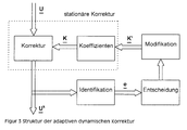
- Zeigt die Struktur der adaptiven dynamischen Korrektur.Shows the structure of the adaptive dynamic correction.
- Figur 4Figure 4
- zeigt ein Strukturbild der Identifikation des Abbildungsfehlers.shows a structural picture of the identification of the imaging error.
- Figur 5Figure 5
- zeigt ein Strukturbild der Koeffizientenmodifikation.shows a structural diagram of the coefficient modification.
- Figur 6Figure 6
- zeigt ein Strukturbild der Adaption der offsetkoeffizienten.shows a structural picture of the adaptation of the offset coefficients.
Der Kern des Verfahrens ist darin zu sehen, jedes Pixel an eine mittlere Kennlinie des gesamten Detektorarrays anzupassen. Der Abbildungsfehler durch die Inhomogenität des Detektorarrays wird vorher durch Referenzmessungen bestimmt. Jedes Pixel wird individuell durch eine Korrektur mit n Koeffizienten korrigiert. Für die Abweichung der individuellen Pixelkennlinien von der mittleren Kennlinie wird dabei ein Polynom n-ter Ordnung gewählt. Die Koeffizienten werden durch die Methode kleinster Fehlerquadrate bestimmt. Voraussetzung für diese Korrekturmethode ist, daß Wechselwirkungen zwischen den Einzelelementen nicht auftreten, bzw. vernachlässigbar sind, da die Korrektur eines Pixels unabhängig von Nachbarpixeln durchgeführt wird.The essence of the method is to see each pixel on a middle one Adapt the characteristic curve of the entire detector array. The aberration due to the inhomogeneity of the detector array Reference measurements determined. Each pixel is individually identified by a Correction corrected with n coefficients. For the deviation of the individual pixel characteristics from the middle characteristic is a Nth order polynomial selected. The coefficients are given by the Least squares method determined. Requirement for this Correction method is that interactions between the Individual elements do not occur or are negligible because the Correction of a pixel is carried out independently of neighboring pixels.
Die Figur 1 zeigt das Kennlinienfeld eines Detektors. Dabei gilt:
- {Uj}:
- Pixelindividuelle Kennlinie
- {〈U〉}:
- Mittlere Kennlinie des Arrays
- [Uj]Tk:
- gemittelter Wert über N Messungen bei Temperatur k des Pixels j.
- [〈U〉]Tk:
- gemittelter Wert über N Messungen bei Temperatur k über alle Pixel
- {U j }:
- Pixel-specific characteristic
- {〈U〉}:
- Middle characteristic of the array
- [U j ] Tk :
- averaged value over N measurements at temperature k of pixel j.
- [〈U〉] Tk :
- averaged value over N measurements at temperature k over all pixels
Das Ziel ist die Anpassung aller individuellen Pixel an die mittlere Kennlinie
des Arrays gemäss folgender Gleichung.
![]()
![]()
Für die Abweichung der individuellen Pixelkennlinien von der mittleren
Kennlinie wird ein Polynom n-ter Ordnung gewählt:
Die Messung der Kennlinie erfolgt an k Stützstellen. Somit ergibt sich die
Abweichung von der mittleren Kennlinie bei der Temperatur i:
Ein Graph dieser Funktion ist in Figur 2 dargestellt.A graph of this function is shown in Figure 2.
Ermittlung der KorrekturkoeffizientenDetermination of the correction coefficients
Die Korrekturkoeffizienten ergeben sich aus der Forderung:

Mit dem Ansatz
Mit den ermittelten Koeffizienten kann die Korrektur der Pixel
vorgenommen werden. Es ergibt sich folgende Korrekturgleichung:
In der Praxis hat sich ein linearer Ansatz zur Kurvenanpassung als nicht ausreichend herausgestellt. Ein nichtlinearer Ansatz ist daher erforderlich. Weiterhin haben sich dafür nicht nur Ansätze mit Polynomentwicklung mindestens 2. Grades, sondern auch andere nichtlineare Ansatze z.B. auf Basis von Exponentialfunktionen als geeignet erwiesen.In practice, a linear approach to curve fitting has proven not to be sufficiently highlighted. A non-linear approach is therefore required. Furthermore, there are not only approaches with polynomial development at least 2nd degree, but also other non-linear approaches e.g. on Based on exponential functions proved to be suitable.
Die für der Korrektur jeden Bildpunktes ermittelten Korrekturkoeffizienten werden in einem Speicher abgelegt und zur Korrektur der Grauwerte der vom Detektorsystem erzeugten Bilder herangezogen. In einem geeignten Bildverarbeitungssystem geschieht dies in Echtzeit bei der Darstellung der Bilder auf einem Bildschirm.The correction coefficients determined for the correction of each pixel are stored in a memory and for correcting the gray values of the Images generated by the detector system are used. In a suitable Image processing system does this in real time when displaying the Pictures on a screen.
Die Ermittlung der Korrekturwerte für die oben beschriebene Globale Korrektur im Ortraum erfolgt im wesentlichen einmalig bei der Kalibrierung der Detektorsysteme bei der Herstellung. Auch können Nachkalibrierungen in grösseren Zeitabständen, wie z.B. bei Wartungen vorgenommen werden.The determination of the correction values for the global described above Correction in place is essentially done once during calibration of the detector systems during manufacture. Recalibrations can also be carried out at longer intervals, e.g. be carried out during maintenance.
Bei einem nach dem Zuvor beschriebenen Verfahren korrigierten Bildes ist ein Driften der Pixelparameter mit großen Zeitkonstanten im Bereich von Minuten bis zu Stunden erkennbar. Für den Betrachter der Bilder erscheint der dadurch entstehende Bildfehler als fixes Ortsrauschen.In the case of an image corrected according to the previously described method drifting the pixel parameters with large time constants in the range of Minutes up to hours recognizable. For the viewer of the pictures appears the resulting image error as a fixed spatial noise.
Die nachfolgend beschriebenen Verfahrensschritte kompensieren die Abbildungsfehler durch ein adaptives Verbessern der Korrekturkoeffizienten jedes Bildpunktes. Basierend auf der Globalen Korrektur im ortsraum kann durch eine Anpassung der Koeffizienten auf den Driftvorgang der Pixelparameter reagiert werden.The process steps described below compensate for the Aberrations by adaptively improving the Correction coefficients of each pixel. Based on the global Correction in the local area can be made by adjusting the coefficients the drifting process of the pixel parameters are reacted to.
Das Ziel der dynamischen Korrektur ist es also, den Drifteffekt der Pixelparameter zu kompensieren und eine Neuermittlung der Korrekturkoeffizienten jedes Bildpunktes an einem Referenzobjekt überflüssig zu machen. Die Information über den Abbildungsfehler muß dabei unabhängig von der betrachteten Szene sein, da in die Adaption der Koeffizienten keine Szeneninformation einfließen darf.The goal of the dynamic correction is therefore the drift effect of the To compensate for pixel parameters and a new determination of the Correction coefficients of each pixel on a reference object to make redundant. The information about the aberration must be independent of the scene being viewed, as in the adaptation of the Coefficients must not include scene information.
Das adaptive dynamische Korrekturverfahren basiert auf einer Selbstanpassung der Korrekturkoeffizienten der globalen stationären Korrektur in regelmäßigen Zeitabständen. Als stationäres Korrekturverfahren wird dabei vorzugsweise die Quadratische Korrektur verwendet. Es können auch andere nichtlineare Ansätze zur Kurvenanpassung verwendet werden. Die dynamische Korrektur stellt eine geschlossene Iterationsschleife aus den Blöcken stationäre Korrektur und Adaption dar, wobei die Adaption aus den Blöcken Identifikation, Entscheidung und Modifikation besteht. über die Identifikation wird aus dem korrigierten Bild eine Information über den Abbildungsfehler eines Einzelpixels unabhängig von der betrachteten Szene gewonnen. Nach einem Entscheidungsprozeß erfolgt die Modifikation der Koeffizienten mit dem Ziel, daß der Abbildungsfehler möglichst schnell gegen Null konvergiert: e → 0. The adaptive dynamic correction method is based on self-adaptation of the correction coefficients of the global stationary correction at regular time intervals. The quadratic correction is preferably used as the stationary correction method. Other nonlinear curve fitting approaches can also be used. The dynamic correction represents a closed iteration loop from the blocks of stationary correction and adaptation, the adaptation consisting of the blocks identification, decision and modification. Information about the aberration of an individual pixel is obtained from the corrected image via the identification, regardless of the scene under consideration. After a decision process, the coefficients are modified with the aim that the imaging error converges to zero as quickly as possible: e → 0 .
Die Figur 3 zeigt ein Ablaufdiagramm der Struktur der adaptiven dynamischen Korrektur. Dabei sind
- U :
- unkorrigiertes Bild
- Uk :
- Korrigiertes Bild
- K :
- Korrekturkoeffizienten
- e :
- Abbildungsfehler
- K' :
- Modifizierte Koeffizienten
- U:
- uncorrected picture
- Uk:
- Corrected picture
- K:
- Correction coefficients
- e:
- Aberrations
- K ':
- Modified coefficients
Aufgrund der Art des Abbildungsfehlers (Impulsrauschen) ist eine Information aus dem lokalen umfeld des jeweiligen Pixels zur Identifikation eines Abbildungsfehlers ausreichend. Dabei muß die Szeneninformation unterdrückt werden, da sie sonst in die Modifikation der Korrekturkoeffizienten einfließt.Due to the nature of the imaging error (impulse noise) is a Information from the local environment of the respective pixel for identification an imaging error is sufficient. The scene information be suppressed, otherwise they would be in the modification of the Correction coefficient is included.
Ein 3x3 Medianfilter hat sich beim vorliegenden Ausführungsbeispiel des Verfahrens als lokaler Filteroperator besonders bewährt. Aus der Differenz des Medianwertes zum Pixelwert wird der Abbildungsfehler bestimmt.A 3x3 median filter has in the present embodiment of the Process as a local filter operator has proven particularly effective. From the difference The imaging error is determined from the median value to the pixel value.
Beim Medianfilter werden die Werte aus dem umfeld des Pixels j zu einer
Zahlenreihe {U k / j} der Größe nach sortiert, wobei gilt
- mit
- U k / j Korrigierter Wert des Pixels j und
U ∼ k / j Medianwert für das Pixel j
- With
- U k / j Corrected value of pixel j and
U ∼ k / j median value for pixel j
Der Abbildungsfehler ergibt sich aus der Differenz des Medianwertes zum
Pixelwert:
- ej
- Abbildungsfehler des Pixels j.
- e j
- Aberration of pixel j.
Mit Hilfe des Abbildungsfehlers kann eine Anpassung der Korrekturkoeffizienten vorgenommen werden.With the help of the aberration, an adjustment of the Correction coefficients are made.
Es ist weiterhin von Vorteil, wenn der Berechnung des Abbildungsfehlers eine zeitliche Mittelung einer Anzahl von Bildern vorrausgeht. Beim vorliegenden Aufführungsbeispiel hat sich eine Mittelung über eine Grössenordnung von ca. 100 Bildern als ausreichend herausgestellt.It is also beneficial when calculating the aberration a temporal averaging of a number of images precedes. At the present performance example has an averaging over a The order of magnitude of approx. 100 pictures was found to be sufficient.
Die Anpassung der Korrekturkoeffizienten orientiert sich stark an der implementierten Quadratischen Korrektur. The adjustment of the correction coefficients is strongly based on the implemented quadratic correction.
Die Figur 4 zeigt ein Strukturbild der Identifikation des Abbildungsfehlers.FIG. 4 shows a structural picture of the identification of the imaging error.
Die Bedingung für eine ideale Identifikation, nämlich keine Information der
Szene mitzuliefern, ist real nicht erfüllt. Es hat sich gezeigt, daß vor allem
Kanten in den Koeffizienten ![]()
![]()
Als einfaches Entscheidungskriterium, im folgenden als update-Kriterium
bezeichnet, wird die Streuung des umfeldes verwendet, das auch für die
Berechnung des Medianwertes herangezogen wird. Dabei wird die
Sortierung der Zahlenreihe, die bei der Ermittlung des Medianwertes
notwendig ist, ausgenutzt.

Die Extremwerte werden für das Entscheidungskriterium ausgenommen. Es
gilt dann:
- mit KUp :
- Entscheidungskriterium
- with K Up :
- Decision criterion
Ein Vergleich zwischen einer Kante und einer Impulsstörung ist in folgender
Tabelle als Beispiel vereinfacht dargestellt.

Die Entscheidung, ob die Koeffizienten modifiziert werden, wird durch
Vergleich des Entscheidungskriterium Kup mit einem Schwellwert Ks
getroffen. Überschreitet der ermittelte Zahlenwert des
Entscheidungskriteriums Kup den vorgegebenen Schwellwert Ks sso findet
keine Änderung des Korrekturkoeffizienten des betrachteten Bildpunktes
statt.
- Ks
- Schwellwert für die Modifikation
- K s
- Modification threshold
Dieses einfache Kriterium liefert gute Ergebnisse.This simple criterion gives good results.
Für die Erhaltung der Bildgüte ist eine Modifikation des Offsetkoeffizienten der Quadratischen Korrektur ausreichend. Die Gain- und Quadratkoeffizienten, welche die Steigung bzw. den nichtlinearen Anteil der Abweichung von der mittleren Kennlinie darstellen, können als zeitkonstant betrachtet werden.A modification of the offset coefficient is necessary to maintain the image quality the quadratic correction is sufficient. The gain and Square coefficients, which are the slope or the non-linear part the deviation from the middle characteristic curve can be as be considered constant in time.
Die einfachste Interpretation des ermittelten Abbildungsfehlers ist die Deutung als Offsetfehler der stationären Korrektur. Mit einem geeigneten Algorithmus ist damit eine Nachführung der Offsetkoeffizienten, die unabhängig von den anderen Koeffizienten sind, möglich. Die Umsetzung liefert gute Ergebnisse und rechtfertigt diese Interpretation.The simplest interpretation of the determined aberration is that Interpretation as offset error of the stationary correction. With a suitable one The algorithm is therefore a tracking of the offset coefficients independent of the other coefficients are possible. The implementation gives good results and justifies this interpretation.
Zur Verbesserung wird im Ausführungsbeispiel ein Integralregler verwendet,
- Oj :
- Offsetkoeffizient des Pixels j
- ej :
- Abbildungsfehler des Pixels j
- kl :
- Gewichtung
- Oj:
- Offset coefficient of pixel j
- ej:
- Aberration of pixel j
- kl:
- weighting
Die Figur 5 zeigt ein Strukturbild der Koeffizientenmodifikation.FIG. 5 shows a structural diagram of the coefficient modification.
Bei dem im Ausführungsbeispiel realisierten Verfahren wurde für alle Pixel die selbe Gewichtung des Abbildungsfehlers verwendet. Denkbar wäre eine pixelindividuelle Gewichtung, um die Adaption auf das jeweilige Pixel abzustimmen. Die Gewichtung bestimmt - zusammen mit der Abtastzeit des update-Zyklus - die Zeitkonstante, mit der auf einen ermittelten Abbildungsfehler reagiert wird. Dabei bedeudet kl→1 schnelle und kl→0 langsame Anpassung.In the method implemented in the exemplary embodiment, the same weighting of the imaging error was used for all pixels. A pixel-specific weighting would be conceivable in order to adapt the adaptation to the respective pixel. The weighting - together with the sampling time of the update cycle - determines the time constant with which to react to a determined imaging error. Here, k l → 1 means fast and k l → 0 slow adjustment.
Mit allen Komponenten ergibt sich das in Figur 6 gezeigte Strukturbild der Adaption der Qffsetkoeffizienten für den dynamischen Teil des Korrekturverfahrens: The structure shown in FIG. 6 results with all components Adaptation of the offset coefficients for the dynamic part of the Correction procedure:
Bei der Realisierung des Korrekturverfahrens hat sich gezeigt, daß zunächst ein hinreichendes, stationäres Korrekturverfahren zu implementieren ist. Eine Quadratische Korrektur hat sich aufgrund der auftretenden Nichtlinearitäten zwischen den Pixelkennlinien als notwendig herausgestellt, damit die Restinhomogenität kleiner als das Zeitrauschen des Detektors wird. Bei der Untersuchung der auftretenden dynamischen Effekte kann ein Driften beobachtet werden, daß sich unter der Voraussetzung der Quadratischen Korrektur als kompensierbar erweist. Durch die Quadratische Korrektur reduzieren sich die durch das Driften entstehenden Inhomogenitäten im wesentlichen auf ein räumliches Impulsrauschen, das durch eine lokale Adaption abgefangen werden kann. Entscheidend ist die Tatsache, daß die Information über die Inhomogenität aus der lokalen Umgebung des Pixels gewonnen werden kann, und nicht eine globale Anpassung wie bei der stationären Korrektur durchgeführt werden muß.When implementing the correction procedure, it was shown that initially a sufficient, stationary correction procedure has to be implemented. A quadratic correction has occurred due to the Nonlinearities between the pixel characteristics are shown to be necessary, thus the residual inhomogeneity is less than the time noise of the detector becomes. When examining the dynamic effects that occur, a Drifting can be observed that under the condition of Quadratic correction proves to be compensable. By the square Correction reduces the drifting Inhomogeneities essentially due to spatial impulse noise can be intercepted by a local adaptation. It is crucial Fact that the information about the inhomogeneity comes from the local Environment of the pixel can be obtained, and not a global one Adaptation as with the stationary correction must be carried out.
Das Verfahren nach der Erfindung setzt sich aus einem parameteradaptiven Reglerkonzept mit Identifikation, Entscheidungsprozeß und Modifikation zusammen. Das adaptive dynamische Korrekturverfahren ermöglicht es, den Detektor über einen weiten Temperaturbereich zu kalibrieren, wobei die Anpassung an den jeweiligen Arbeitsbereich, der sich üblicherweise nur über wenige Kelvin erstreckt, selbstanpassend durch die Korrektur erfolgt. Ein Problem des Verfahrens bleibt der Rest an Szeneninformation, die bei der Ermittlung des Abbildungsfehlers nicht unterdrückt wird und mit in die Koeffizienten eingeht. Die Folgen sind das Einfrieren von Kanten und eine Verschmierung von Kanten bei langer Betrachtung von fixen Szenen, wobei aber durch die Wahl der Parameter update-Schwellwert und Gewichtung des Abbildungsfehlers ein tragbarer Kompromiß eingestellt werden kann.The method according to the invention consists of a parameter-adaptive Controller concept with identification, decision-making process and modification together. The adaptive dynamic correction method enables the Calibrate detector over a wide temperature range, the Adaptation to the respective work area, which is usually only extends over a few Kelvin, self-adapting through the correction. A problem with the method remains the rest of the scene information the determination of the imaging error is not suppressed and included in the Coefficient is received. The consequences are freezing of edges and one Smearing of edges when looking at fixed scenes for a long time, whereby but by choosing the parameters update threshold and weighting a tolerable compromise can be set.
Abschließend läßt sich sagen, daß mit der vorliegenden Erfindung die Möglichkeit einer langzeitstabilen Korrektur von zweidimensionalen Infrarotdetektoren ohne ständige Neukalibration durch eine thermische Referenzquelle erreicht wird.In conclusion, it can be said that with the present invention the Possibility of long-term stable correction of two-dimensional Infrared detectors without constant recalibration through a thermal Reference source is reached.
Claims (7)
Applications Claiming Priority (2)
| Application Number | Priority Date | Filing Date | Title |
|---|---|---|---|
| DE19715983A DE19715983C1 (en) | 1997-04-17 | 1997-04-17 | Method for correcting the gray values of images from a digital infrared camera |
| DE19715983 | 1997-04-17 |
Publications (3)
| Publication Number | Publication Date |
|---|---|
| EP0873011A2 true EP0873011A2 (en) | 1998-10-21 |
| EP0873011A3 EP0873011A3 (en) | 1999-01-13 |
| EP0873011B1 EP0873011B1 (en) | 2004-11-17 |
Family
ID=7826741
Family Applications (1)
| Application Number | Title | Priority Date | Filing Date |
|---|---|---|---|
| EP98106137A Expired - Lifetime EP0873011B1 (en) | 1997-04-17 | 1998-04-03 | Method for correcting grey scale values in images of a digital infrared camera |
Country Status (4)
| Country | Link |
|---|---|
| US (1) | US6075903A (en) |
| EP (1) | EP0873011B1 (en) |
| DE (1) | DE19715983C1 (en) |
| IL (1) | IL124104A (en) |
Cited By (1)
| Publication number | Priority date | Publication date | Assignee | Title |
|---|---|---|---|---|
| EP1206128A1 (en) * | 2000-11-10 | 2002-05-15 | Zeiss Optronik GmbH | Method for equalising technologically caused inhomogeneities in single image pickup detector elements |
Families Citing this family (24)
| Publication number | Priority date | Publication date | Assignee | Title |
|---|---|---|---|---|
| DE19816003C2 (en) * | 1998-04-09 | 2001-05-17 | Aeg Infrarot Module Gmbh | Method for correcting the gray values of images from a digital infrared camera |
| US6330371B1 (en) * | 1998-10-19 | 2001-12-11 | Raytheon Company | Adaptive non-uniformity compensation using feedforward shunting and min-mean filter |
| CN1308670C (en) * | 2000-11-10 | 2007-04-04 | 爱科来株式会社 | Measuring method and instrument comprising image sensor |
| US7016550B2 (en) * | 2002-04-19 | 2006-03-21 | Lockheed Martin Corporation | Scene-based non-uniformity offset correction for staring arrays |
| DE10216806B4 (en) | 2002-04-16 | 2006-11-23 | Institut Für Mikroelektronik Stuttgart | Method and device for FPN correction of image signal values of an image sensor |
| DE10255021B4 (en) * | 2002-11-25 | 2007-02-22 | Carl Zeiss Optronics Gmbh | Method and device for generating image data of a scene taking into account inhomogeneities in the signal sensitivities of sensor elements in scanning imaging devices |
| DE10340515B4 (en) * | 2003-09-03 | 2007-04-19 | Carl Zeiss Optronics Gmbh | Method and device for inhomogeneity correction and calibration of optronic cameras with the aid of recorded images and representation of physical quantities |
| DE102005057538A1 (en) * | 2005-12-01 | 2006-11-23 | Siemens Ag | X ray solid object detector system for medical use has a matrix of photodiode detectors with field corrections applied |
| DE102006060001A1 (en) * | 2006-12-19 | 2008-07-03 | Siemens Ag | Determine the Fixed Pattern Noise during camera operation |
| US20080212895A1 (en) * | 2007-01-09 | 2008-09-04 | Lockheed Martin Corporation | Image data processing techniques for highly undersampled images |
| US8073285B2 (en) * | 2007-08-27 | 2011-12-06 | Ancestry.Com Operations Inc. | User interface methods and systems for image brightness and contrast |
| US8370759B2 (en) | 2008-09-29 | 2013-02-05 | Ancestry.com Operations Inc | Visualizing, creating and editing blending modes methods and systems |
| DE102008058798B4 (en) * | 2008-11-24 | 2011-02-17 | Carl Zeiss Optronics Gmbh | Stereo camera devices, methods for the continuous automatic calibration of a stereo camera device, computer program, computer program product and monitoring device for wind turbines, buildings with transparent areas, runways and / or flight corridors of airports |
| DE102008059818A1 (en) * | 2008-12-01 | 2010-06-10 | Diehl Bgt Defence Gmbh & Co. Kg | Method of reducing crosstalk in a multi-field sensor system |
| DE102009030568B3 (en) * | 2009-06-26 | 2010-10-07 | Lfk-Lenkflugkörpersysteme Gmbh | Method for correcting the gray values of an IR detector |
| DE102010008456A1 (en) * | 2010-02-18 | 2011-08-18 | Testo AG, 79853 | Method for extracting an IR image and thermal imaging camera |
| DE102010013377B4 (en) * | 2010-03-30 | 2012-02-02 | Testo Ag | Image processing method and thermal imaging camera |
| DE102010023168B4 (en) | 2010-06-07 | 2016-05-19 | Esw Gmbh | Method and device for correcting non-uniform sensitivity of detector elements in thermal imaging cameras |
| DE102010023170A1 (en) * | 2010-06-07 | 2011-12-08 | Esw Gmbh | Thermal imaging camera and method for recording and / or modification and reproduction of thermal images of a scene and / or an object |
| US8929650B2 (en) | 2012-11-28 | 2015-01-06 | International Business Machines Corporation | Image color correction |
| DE102014108971B4 (en) * | 2014-06-26 | 2020-08-13 | Technische Universität Dresden | Calibration procedures and correction procedures for a shutterless infrared camera system and the like |
| DE102015109878B3 (en) * | 2015-06-19 | 2016-07-28 | Basler Ag | Correction of a patterned image defect |
| CN105516622B (en) * | 2015-09-25 | 2018-10-19 | 中国科学院上海技术物理研究所 | A kind of adaptive Opsonizing method of infrared signal |
| DE102019112626A1 (en) * | 2019-05-14 | 2020-11-19 | Leica Camera Aktiengesellschaft | Method for generating an image signal |
Citations (4)
| Publication number | Priority date | Publication date | Assignee | Title |
|---|---|---|---|---|
| US4975864A (en) * | 1989-01-26 | 1990-12-04 | Hughes Aircraft Company | Scene based nonuniformity compensation for starting focal plane arrays |
| EP0653882A1 (en) * | 1993-11-15 | 1995-05-17 | Hughes Aircraft Company | Scene based nonuniformity correction for scanning infrared sensors |
| US5514865A (en) * | 1994-06-10 | 1996-05-07 | Westinghouse Electric Corp. | Dither image scanner with compensation for individual detector response and gain correction |
| WO1997005742A1 (en) * | 1995-07-31 | 1997-02-13 | The Secretary Of State For Defence | Thermal sensing system having a fast response calibration device |
Family Cites Families (2)
| Publication number | Priority date | Publication date | Assignee | Title |
|---|---|---|---|---|
| SE9201182L (en) * | 1992-04-13 | 1993-06-28 | Dv Sweden Ab | SETTING TO DETECT AND REMOVE ERRORS EXCEEDING A SPECIFIC CONTRAST IN DIGITAL VIDEO SIGNALS |
| CA2110368C (en) * | 1992-12-07 | 1999-11-23 | Gary M. Lindgren | Wide dynamic range non-uniformity compensation for infrared focal plane arrays |
-
1997
- 1997-04-17 DE DE19715983A patent/DE19715983C1/en not_active Expired - Lifetime
-
1998
- 1998-04-03 EP EP98106137A patent/EP0873011B1/en not_active Expired - Lifetime
- 1998-04-15 IL IL12410498A patent/IL124104A/en not_active IP Right Cessation
- 1998-04-16 US US09/061,147 patent/US6075903A/en not_active Expired - Fee Related
Patent Citations (4)
| Publication number | Priority date | Publication date | Assignee | Title |
|---|---|---|---|---|
| US4975864A (en) * | 1989-01-26 | 1990-12-04 | Hughes Aircraft Company | Scene based nonuniformity compensation for starting focal plane arrays |
| EP0653882A1 (en) * | 1993-11-15 | 1995-05-17 | Hughes Aircraft Company | Scene based nonuniformity correction for scanning infrared sensors |
| US5514865A (en) * | 1994-06-10 | 1996-05-07 | Westinghouse Electric Corp. | Dither image scanner with compensation for individual detector response and gain correction |
| WO1997005742A1 (en) * | 1995-07-31 | 1997-02-13 | The Secretary Of State For Defence | Thermal sensing system having a fast response calibration device |
Cited By (1)
| Publication number | Priority date | Publication date | Assignee | Title |
|---|---|---|---|---|
| EP1206128A1 (en) * | 2000-11-10 | 2002-05-15 | Zeiss Optronik GmbH | Method for equalising technologically caused inhomogeneities in single image pickup detector elements |
Also Published As
| Publication number | Publication date |
|---|---|
| EP0873011A3 (en) | 1999-01-13 |
| US6075903A (en) | 2000-06-13 |
| IL124104A (en) | 2001-06-14 |
| DE19715983C1 (en) | 1998-09-24 |
| EP0873011B1 (en) | 2004-11-17 |
Similar Documents
| Publication | Publication Date | Title |
|---|---|---|
| EP0873011B1 (en) | Method for correcting grey scale values in images of a digital infrared camera | |
| DE4411179B4 (en) | image capture device | |
| DE3535753C1 (en) | Signal processor | |
| DE4108288C2 (en) | ||
| DE102010023168B4 (en) | Method and device for correcting non-uniform sensitivity of detector elements in thermal imaging cameras | |
| DE69627755T2 (en) | Method and device for the temporary noise filtering of an image sequence | |
| DE69825090T2 (en) | Image acquisition method and apparatus | |
| DE102005010986B4 (en) | Method and device for taking a thermal image | |
| DE19718799A1 (en) | Imaging and / or scanning device in a raster mode with a device for compensating for image degradation caused by environmental influences | |
| DE60310533T2 (en) | IMPROVEMENTS RELATED TO THE CALIBRATION OF INFRARED CAMERAS | |
| EP1206128B1 (en) | Method for equalising technologically caused inhomogeneities in single image pickup detector elements | |
| EP1814079B1 (en) | Method and device for correcting the brightness of a raw image produced using a sensor matrix | |
| WO2017093227A1 (en) | Method and device for image correction | |
| EP3524925A1 (en) | Method for the determination of characteristic curve correction factors of a matrix detector in the infrared spectrum range | |
| EP0558116B1 (en) | Method for radiograms and device suited therefor | |
| CN115439345A (en) | Stripe noise suppression method and system of cross-track wide-width scanning camera | |
| DE102017112484A1 (en) | Method and device for image correction | |
| US4956873A (en) | Image processing apparatus | |
| DE10255021B4 (en) | Method and device for generating image data of a scene taking into account inhomogeneities in the signal sensitivities of sensor elements in scanning imaging devices | |
| DE112020007355T5 (en) | INFRARED IMAGE PROCESSING DEVICE AND INFRARED IMAGE PROCESSING METHOD | |
| DE4340994C2 (en) | Method for correcting influences of the AC voltage coupling in a signal chain of scanning opto-electronic sensors | |
| WO1998026579A1 (en) | Method for archiving master images by digital image data processing | |
| DE10144388B4 (en) | Method and device for controlling objects | |
| DE10333712A1 (en) | Failure reduced depiction method e.g. for digital cameras, microscopes, involves illustrating object by optical mechanism and has illustration unit to collect intensity values | |
| DE10020311B4 (en) | Method and device for recording optical properties of a relatively moving scene |
Legal Events
| Date | Code | Title | Description |
|---|---|---|---|
| PUAI | Public reference made under article 153(3) epc to a published international application that has entered the european phase |
Free format text: ORIGINAL CODE: 0009012 |
|
| AK | Designated contracting states |
Kind code of ref document: A2 Designated state(s): FR GB IT NL |
|
| AX | Request for extension of the european patent |
Free format text: AL;LT;LV;MK;RO;SI |
|
| PUAL | Search report despatched |
Free format text: ORIGINAL CODE: 0009013 |
|
| AK | Designated contracting states |
Kind code of ref document: A3 Designated state(s): AT BE CH CY DE DK ES FI FR GB GR IE IT LI LU MC NL PT SE |
|
| AX | Request for extension of the european patent |
Free format text: AL;LT;LV;MK;RO;SI |
|
| 17P | Request for examination filed |
Effective date: 19990518 |
|
| AKX | Designation fees paid |
Free format text: FR GB IT NL |
|
| REG | Reference to a national code |
Ref country code: DE Ref legal event code: 8566 |
|
| 17Q | First examination report despatched |
Effective date: 20030722 |
|
| GRAP | Despatch of communication of intention to grant a patent |
Free format text: ORIGINAL CODE: EPIDOSNIGR1 |
|
| GRAS | Grant fee paid |
Free format text: ORIGINAL CODE: EPIDOSNIGR3 |
|
| GRAA | (expected) grant |
Free format text: ORIGINAL CODE: 0009210 |
|
| AK | Designated contracting states |
Kind code of ref document: B1 Designated state(s): FR GB IT NL |
|
| REG | Reference to a national code |
Ref country code: GB Ref legal event code: FG4D Free format text: NOT ENGLISH |
|
| GBT | Gb: translation of ep patent filed (gb section 77(6)(a)/1977) |
Effective date: 20050124 |
|
| PLBE | No opposition filed within time limit |
Free format text: ORIGINAL CODE: 0009261 |
|
| STAA | Information on the status of an ep patent application or granted ep patent |
Free format text: STATUS: NO OPPOSITION FILED WITHIN TIME LIMIT |
|
| ET | Fr: translation filed | ||
| 26N | No opposition filed |
Effective date: 20050818 |
|
| PGFP | Annual fee paid to national office [announced via postgrant information from national office to epo] |
Ref country code: NL Payment date: 20150420 Year of fee payment: 18 |
|
| REG | Reference to a national code |
Ref country code: FR Ref legal event code: PLFP Year of fee payment: 19 |
|
| REG | Reference to a national code |
Ref country code: NL Ref legal event code: MM Effective date: 20160501 |
|
| PG25 | Lapsed in a contracting state [announced via postgrant information from national office to epo] |
Ref country code: NL Free format text: LAPSE BECAUSE OF NON-PAYMENT OF DUE FEES Effective date: 20160501 |
|
| REG | Reference to a national code |
Ref country code: FR Ref legal event code: PLFP Year of fee payment: 20 |
|
| PGFP | Annual fee paid to national office [announced via postgrant information from national office to epo] |
Ref country code: FR Payment date: 20170419 Year of fee payment: 20 Ref country code: GB Payment date: 20170419 Year of fee payment: 20 |
|
| PGFP | Annual fee paid to national office [announced via postgrant information from national office to epo] |
Ref country code: IT Payment date: 20170424 Year of fee payment: 20 |
|
| REG | Reference to a national code |
Ref country code: GB Ref legal event code: PE20 Expiry date: 20180402 |
|
| PG25 | Lapsed in a contracting state [announced via postgrant information from national office to epo] |
Ref country code: GB Free format text: LAPSE BECAUSE OF EXPIRATION OF PROTECTION Effective date: 20180402 |