EP0483530A2 - Method and device for offset and response harmonization in an electrooptical linear or mosaic sensor - Google Patents
Method and device for offset and response harmonization in an electrooptical linear or mosaic sensor Download PDFInfo
- Publication number
- EP0483530A2 EP0483530A2 EP91116657A EP91116657A EP0483530A2 EP 0483530 A2 EP0483530 A2 EP 0483530A2 EP 91116657 A EP91116657 A EP 91116657A EP 91116657 A EP91116657 A EP 91116657A EP 0483530 A2 EP0483530 A2 EP 0483530A2
- Authority
- EP
- European Patent Office
- Prior art keywords
- detector
- image
- detectors
- offset
- radiation
- Prior art date
- Legal status (The legal status is an assumption and is not a legal conclusion. Google has not performed a legal analysis and makes no representation as to the accuracy of the status listed.)
- Granted
Links
- 238000000034 method Methods 0.000 title claims abstract description 25
- 230000005855 radiation Effects 0.000 claims abstract description 22
- 230000004043 responsiveness Effects 0.000 claims description 16
- 238000012935 Averaging Methods 0.000 claims description 7
- 238000013528 artificial neural network Methods 0.000 claims description 5
- XEEYBQQBJWHFJM-UHFFFAOYSA-N Iron Chemical compound [Fe] XEEYBQQBJWHFJM-UHFFFAOYSA-N 0.000 claims description 4
- 238000006073 displacement reaction Methods 0.000 claims description 3
- 230000005284 excitation Effects 0.000 claims description 3
- 230000003595 spectral effect Effects 0.000 claims description 3
- 238000001931 thermography Methods 0.000 claims description 3
- 229910052742 iron Inorganic materials 0.000 claims description 2
- 239000000463 material Substances 0.000 claims description 2
- 238000005259 measurement Methods 0.000 claims description 2
- 238000013016 damping Methods 0.000 claims 1
- 238000003384 imaging method Methods 0.000 claims 1
- 230000007935 neutral effect Effects 0.000 abstract 2
- 230000006855 networking Effects 0.000 description 7
- 230000010354 integration Effects 0.000 description 5
- 238000012937 correction Methods 0.000 description 3
- 238000013213 extrapolation Methods 0.000 description 3
- 229910000661 Mercury cadmium telluride Inorganic materials 0.000 description 2
- 230000035945 sensitivity Effects 0.000 description 2
- 230000015572 biosynthetic process Effects 0.000 description 1
- MCMSPRNYOJJPIZ-UHFFFAOYSA-N cadmium;mercury;tellurium Chemical compound [Cd]=[Te]=[Hg] MCMSPRNYOJJPIZ-UHFFFAOYSA-N 0.000 description 1
- 230000007547 defect Effects 0.000 description 1
- 230000001419 dependent effect Effects 0.000 description 1
- 238000013461 design Methods 0.000 description 1
- 230000001627 detrimental effect Effects 0.000 description 1
- 238000010191 image analysis Methods 0.000 description 1
- 230000001771 impaired effect Effects 0.000 description 1
- 238000004519 manufacturing process Methods 0.000 description 1
- 230000001537 neural effect Effects 0.000 description 1
- 230000001105 regulatory effect Effects 0.000 description 1
- 239000004065 semiconductor Substances 0.000 description 1
- 239000000725 suspension Substances 0.000 description 1
Images


Classifications
-
- H—ELECTRICITY
- H04—ELECTRIC COMMUNICATION TECHNIQUE
- H04N—PICTORIAL COMMUNICATION, e.g. TELEVISION
- H04N1/00—Scanning, transmission or reproduction of documents or the like, e.g. facsimile transmission; Details thereof
- H04N1/04—Scanning arrangements, i.e. arrangements for the displacement of active reading or reproducing elements relative to the original or reproducing medium, or vice versa
- H04N1/19—Scanning arrangements, i.e. arrangements for the displacement of active reading or reproducing elements relative to the original or reproducing medium, or vice versa using multi-element arrays
- H04N1/191—Scanning arrangements, i.e. arrangements for the displacement of active reading or reproducing elements relative to the original or reproducing medium, or vice versa using multi-element arrays the array comprising a one-dimensional array, or a combination of one-dimensional arrays, or a substantially one-dimensional array, e.g. an array of staggered elements
- H04N1/1911—Simultaneously or substantially simultaneously scanning picture elements on more than one main scanning line, e.g. scanning in swaths
- H04N1/1913—Scanning adjacent picture elements in different scans of the array, e.g. in complementary checkerboard patterns
- H04N1/1915—Scanning adjacent picture elements in different scans of the array, e.g. in complementary checkerboard patterns with subscan displacement of the array between successive scans
-
- H—ELECTRICITY
- H04—ELECTRIC COMMUNICATION TECHNIQUE
- H04N—PICTORIAL COMMUNICATION, e.g. TELEVISION
- H04N1/00—Scanning, transmission or reproduction of documents or the like, e.g. facsimile transmission; Details thereof
- H04N1/04—Scanning arrangements, i.e. arrangements for the displacement of active reading or reproducing elements relative to the original or reproducing medium, or vice versa
- H04N1/19—Scanning arrangements, i.e. arrangements for the displacement of active reading or reproducing elements relative to the original or reproducing medium, or vice versa using multi-element arrays
- H04N1/195—Scanning arrangements, i.e. arrangements for the displacement of active reading or reproducing elements relative to the original or reproducing medium, or vice versa using multi-element arrays the array comprising a two-dimensional array or a combination of two-dimensional arrays
- H04N1/19505—Scanning picture elements spaced apart from one another in at least one direction
- H04N1/1951—Scanning picture elements spaced apart from one another in at least one direction in one direction
-
- H—ELECTRICITY
- H04—ELECTRIC COMMUNICATION TECHNIQUE
- H04N—PICTORIAL COMMUNICATION, e.g. TELEVISION
- H04N23/00—Cameras or camera modules comprising electronic image sensors; Control thereof
- H04N23/58—Means for changing the camera field of view without moving the camera body, e.g. nutating or panning of optics or image sensors
-
- H—ELECTRICITY
- H04—ELECTRIC COMMUNICATION TECHNIQUE
- H04N—PICTORIAL COMMUNICATION, e.g. TELEVISION
- H04N25/00—Circuitry of solid-state image sensors [SSIS]; Control thereof
- H04N25/20—Circuitry of solid-state image sensors [SSIS]; Control thereof for transforming only infrared radiation into image signals
- H04N25/21—Circuitry of solid-state image sensors [SSIS]; Control thereof for transforming only infrared radiation into image signals for transforming thermal infrared radiation into image signals
-
- H—ELECTRICITY
- H04—ELECTRIC COMMUNICATION TECHNIQUE
- H04N—PICTORIAL COMMUNICATION, e.g. TELEVISION
- H04N25/00—Circuitry of solid-state image sensors [SSIS]; Control thereof
- H04N25/60—Noise processing, e.g. detecting, correcting, reducing or removing noise
- H04N25/67—Noise processing, e.g. detecting, correcting, reducing or removing noise applied to fixed-pattern noise, e.g. non-uniformity of response
- H04N25/671—Noise processing, e.g. detecting, correcting, reducing or removing noise applied to fixed-pattern noise, e.g. non-uniformity of response for non-uniformity detection or correction
- H04N25/672—Noise processing, e.g. detecting, correcting, reducing or removing noise applied to fixed-pattern noise, e.g. non-uniformity of response for non-uniformity detection or correction between adjacent sensors or output registers for reading a single image
-
- H—ELECTRICITY
- H04—ELECTRIC COMMUNICATION TECHNIQUE
- H04N—PICTORIAL COMMUNICATION, e.g. TELEVISION
- H04N25/00—Circuitry of solid-state image sensors [SSIS]; Control thereof
- H04N25/48—Increasing resolution by shifting the sensor relative to the scene
Definitions
- the invention is primarily but not exclusively useful for radiation receivers which are used in the infrared spectral range (approx. 2 ⁇ m to 14 ⁇ m) in thermal imaging devices. For physical and technological reasons, certain detector defects in this spectral range are much more critical than in the visible. These are offset or differences in offset and differences in responsiveness.
- the current or voltage that is not caused by the signal radiation is sometimes referred to as offset, sometimes also referred to as dark or leakage current or voltage. Responsiveness is the change in current or voltage as a function of a change in radiation to a detector, the change in radiation generally being assumed to be proportional to the change in temperature.
- the harmonization can be carried out using a microscan.
- a microscan is known from the company magazine "Kontron Image Analysis, Prog. Res. 3000, Production Formation” from June 1989, pp. 2-15.
- two detectors can each assume identical positions in relation to the image or object space. To restore the resolution of the original black and white image, different color information is superimposed. There is nothing in this document to show that such a “staggering" can be useful for harmonizing offset and responsiveness.
- a detector system in which each of the elements takes on four positions in succession due to the scanning movement of a mirror, which roughly correspond to the corner points of a rectangle - the simplest possible case - is e.g. known from EP-A-0 133 890.
- a disadvantage of this embodiment is the very specific definition of only four scanning positions.
- the nutating movement of the mirror also requires a gimbal that is comparatively complex.
- Integrated semiconductor detectors are then known for television cameras in the visible range, which consist, for example, of 580 x 700 detector elements.
- the signals are read out using CCDs (charged coupled devices). It is characteristic of this type of detector elements that each of them corresponds to a pixel. The resolution of an image therefore depends on the number of detectors.
- conventional thermal imaging devices use a few detector elements, a maximum of about 100, which are guided over the image field by means of mechanical-optical methods, so that such a mosaic detector delivers signals from many pixels.
- increasing the number of detectors to values that are used in the visible in CCDs encounters cost and technological problems in the infrared.
- HgCdTe mercury cadmium telluride
- mosaics of at most approximately 128 x 128 to a maximum of 256 x 256 detector elements are acceptable in this regard.
- Another problem is represented by the spaces between the detectors. Often they are comparatively large for technological reasons, so that a lot of radiation also falls into this insensitive area. This not only reduces the sensitivity of the arrangement, but additional information is lost, which contributes to falsification of the image. This phenomenon is known as "aliasing".
- the object of the invention is seen in the creation of an inexpensive, deterministic method for harmonization for offset voltages and different responsivities; this task can also be linked to the known task of eliminating or reducing the aliasing phenomenon.
- This object is achieved according to the invention by the characterizing features of claim 1. With a comparatively simple networking, a scene (temperature) related deterministic offset correction and responsiveness harmonization can be carried out.
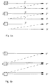
- FIG. 1a shows the principle of compensation. It shows the compensated output voltage of two detectors 1 and 2, which are arranged according to FIG. 1b. Detector 1 is moved from its rest position 1 'to position 2' (the rest position of detector 2) and optionally to position 5 '. Detector 2 is then in turn moved from position 2 'to 5' (and optionally to n ').
- the scene radiation (temperature) in FIG. 1 may increase from left to right, so that the output voltages of the detectors also increase. Because of the detector inhomogeneities, these output voltages will be different. But now the detectors in position 2 'receive the same amount of radiation. This allows electrical compensation of the output voltage ( offset compensation).
- Fig. 2a a section of four detector elements 1 to 4 is assumed from a mosaic detector in which a conventional two-by-two microscan is carried out.
- the detector element 1 assumes the positions 1 ', a, c and d one after the other.
- the aliasing problem is addressed in that the positions a, c and d fall into spaces between the individual detector elements.
- FIG. 2b networking is carried out which can serve to harmonize the offset and responsiveness according to FIG. 1: If detector 1 takes positions 1 ', 2' 4 'and 3' one after the other, detector 2 takes, among other things Positions 2 'and 4'.
- FIG. 3 which shows a larger section of the mosaic according to FIG. 2, demonstrates the principle according to FIGS. 2a and 2b, that is to say the conventional microscan and the networking.
- the detector 1 takes, for example, the positions 1 ', a, 2', b, c, d, 3 ', e, 4' one after the other, the positions denoted by the letters a to e denoting a conventional microscan for filling the gaps , whereas positions 1 ', 2' 3 'and 4' are used for networking and thus for the harmonization of offset and reponsiveness (gain).
- the conventional scanning method of FIG. 2a can also be used to extrapolate to harmonize offset and responsiveness, see FIG. 4.
- the geometric arrangement corresponds to FIG. 3: If detector 1 is moved from position 1 'to a, then Because of the small change in location, the voltage of detector 1 at position 2 'can be predicted with good approximation by linear extrapolation. However, offset harmonization with detector 2 is possible as a result. The extrapolation error will be even smaller if the harmonization is done by averaging, since - provided that the scene does not remain constant - the deviations from linearity will be zero on average.
- the voltage of the detector 1 is extrapolated from a to 2 '.
- the voltage of the detector 2 can be extrapolated from position 2 'to a, so that the output voltage for two identical positions (a and 2') is known, albeit extrapolated, for two detectors. This again results in the case that the identical change in radiation can be used to harmonize the responsiveness of detectors 1 and 2.
- two detectors each receive the same amount of radiation. This can also be done by defocusing. This results in an averaging over a certain area of the scene which is dependent on the degree of defocusing and which can be adapted to the scene content. If one now selects a second position of the defocusing, one will generate a radiation field which corresponds to an average value, but which will differ from the first-mentioned average value. This results in a change in the radiation which is identical in the case of neighboring detectors and can thus harmonize the responsiveness (gain) .
- the compensation voltages are expediently determined by averaging from many measurements.
- the averaging ensures that the harmonization voltages or harmonization coefficients are not impaired by the noise of the detectors in the limit case. Since the harmonization changes only slightly from one image to the next, the noise of the system will only increase insignificantly. Finally, this ensures that the compensation for sudden changes, e.g. the lighting up of a point object, does not compensate for the useful signal.
- FIG. 5a shows in a line detector a conventional line interlacing method (interlace) in which detector 1, after passing through line 1 ′′, also scans line a ′ between the rest position of detectors 1 and 2.
- Fig. 5b shows the application of the method according to the invention: Here gropes detector 1 lines 1 '' and line 2 '', detector 2 lines 2 '' and 3 ''. 6 shows an example of the output signals of detectors 1 and 2 for line 2 ′′.
- the mean values of the detector voltages U 1 and U 2 are different, but can be compensated for in accordance with the method according to the invention, since the same scene radiation is present. Because of the different responsivities, the deviations from the mean will also be different. These inequalities can also be compensated for by determining the fluctuations around said mean value, for example measuring the effective value of the AC voltage component (RMS value).
- RMS value effective value
- a mirror is usually used for scanning.
- these systems work unidirectionally, i.e. the mirror is used to scan the scene for image acquisition, for example, from left to right, the return of the mirror to the starting position (from right to left) is not used for image acquisition, among other things because with detector arrangements with TDI (time-delayed integration ) this TDI only leads to a meaningful image structure in one direction. If the electrical integration is nevertheless carried out in the case of a mirror return, the integrated signals will not come from identical pixels, rather the output signal will be the average of a number of points which are close together.
- U i , U j , U k are voltages of detectors 100 which are linked in an intermediate layer 101 and deliver harmonized responsivities R i , R j , R k 102 at the output .
- FIG. 8 shows a section of a mosaic detector in which the image shifting means 20 (FIG. 9), e.g. a scanning mirror or a transparent plate, by means of electromagnetic force, which performs nutating movement in accordance with the rectangular scanning loop, which is state of the art.
- the image shifting means 20 e.g. a scanning mirror or a transparent plate
- electromagnetic force which performs nutating movement in accordance with the rectangular scanning loop
- the image shifting means 20 is held in the center on its right end 15 in the direction of view by means of a ball bearing 16.
- joints, torsion bars, torsion springs and the like are also used for the holder. conceivable without thereby leaving the scope of the invention. In each of these cases, however, the storage or suspension must take place in such a way that the image shifting means can both be rotated about the axis of symmetry running through the attachment point and tilted in the plane perpendicular to the image shifting means.
- a specially designed magnetic drive and positioning magnet system 19-13 or 19'-13 ' is then provided in the corner areas of the opposite end face 17, which is the subject of the following description:
- the mirror or the transparent plate each have these areas a permanent magnet 19 or 19 'attached, the free end, for example to represent the South Pole.
- Opposite these south poles is e.g. each have an essentially U-shaped structure, the leg 10 or 10 'of which is also a permanent magnet, has a pole shoe made of soft iron and acts accordingly as the north pole.
- the leg 11 or 11 ' consists of an electromagnet with the two coils 12 and 13 or 12' and 13 '. If leg 11 or 11 'is magnetized via excitation coil 12 and a corresponding current flow in such a way that its forces with the same polarity are as strong as those of leg 10 or 10', the image shifting means 20 and its two magnets 19 and 19 'take a middle position between the two legs 10 and 11. If, on the other hand, the current in the coil 12 or 12 'becomes stronger or weaker, the image shifting means and magnets assume a correspondingly eccentric position, that is to say the same then find their rest position somewhat more in the direction of the legs 10 or 11 or 10' or 11 '.
- the image offset means 20 moves up and down with its magnet-side end in the direction of the double arrow 18, which is also referred to as a tilting movement. If, on the other hand, the magnets are excited in opposite directions, the image shifting means rotates around the axis of symmetry running through its attachment point 16.
- the two drive circuits for rotary and tilting movements can be separated by starting up the second coil 13 or 13 ', coil 12 from leg 11 with coil 12' from leg 11 'being excited in the same direction and coil 13 with coil 13' being excited in opposite directions.
- FIG. 10 Another embodiment of the invention is shown in FIG. 10.
- the image displacement means 20 also with all four corners or via corresponding permanent magnets 19 to 19 '' 'in magnetic drive and positioning magnet systems 10, 11, 12, 13, to 10 '' ', 11' '', 12 '' ', 13' '' can be stored.
- the control described above - now all eight coils 12, 13 to 12 '' ', 13' '' - can cause a nutation or wobble movement of the mirror.
- the storage of a corner point is drawn out on its own and on an enlarged scale, and it can also be seen that the maximum "stroke" of the nutation or wobble movement is determined by the distance of the mirror from the two legs.
Abstract
Description
Die Erfindung betrifft ein Verfahren zur Harmonisierung für Offset und Responsivität (= Empfindlichkeit, Gain) bei einem elektrooptischen Zeilen- oder Mosaikdetektor sowie eine Vorrichtung einmal zur Durchführung dieses Verfahrens sowie für eine allgemeine Mikroabtastung.The invention relates to a method for harmonizing offset and responsiveness (= sensitivity, gain) in an electro-optical line or mosaic detector and to a device for carrying out this method and for general micro-scanning.
Die Erfindung ist vornehmlich aber nicht ausschließlich für Strahlungsempfänger nützlich, die im infraroten Spektralbereich (ca. 2 µm bis 14 µm) in Wärmebildgeräten eingesetzt sind. In diesem Spektralbereich sind aus physikalischen und technologischen Gründen bestimmte Detektormängel sehr viel kritischer als im Sichtbaren. Es sind dies namentlich Offset bzw. Unterschiede im Offset und Unterschiede in der Responsivität. Als Offset wird hier der Strom oder die Spannung bezeichnet, der bzw. die nicht von der Signalstrahlung hervorgerufen wird, gelegentlich auch als Dunkel- oder Leckstrom bzw. -spannung bezeichnet. Responsivität ist die Änderung von Strom oder Spannung als Funktion einer Änderung der Strahlung auf einen Detektor, wobei die Strahlungsänderung gemeinhin als proportional zur Temperaturänderung angenommen wird.The invention is primarily but not exclusively useful for radiation receivers which are used in the infrared spectral range (approx. 2 μm to 14 μm) in thermal imaging devices. For physical and technological reasons, certain detector defects in this spectral range are much more critical than in the visible. These are offset or differences in offset and differences in responsiveness. Here, the current or voltage that is not caused by the signal radiation is sometimes referred to as offset, sometimes also referred to as dark or leakage current or voltage. Responsiveness is the change in current or voltage as a function of a change in radiation to a detector, the change in radiation generally being assumed to be proportional to the change in temperature.
Die Harmonisierung kann in einer Ausformung der Erfindung unter Verwendung eines Mikroscans erfolgen. Ein solcher Mikroscan ist aus der Firmenzeitschrift "Kontron Bildanalyse, Prog. Res. 3000, Produktionsformation" vom Juni 1989, S. 2-15, bekannt. Auch hier können jeweils zwei Detektoren - bezogen auf den Bild- bzw. Objektraum - identische Positionen einnehmen. Um die Auflösung des ursprünglichen Schwarz-Weiß-Bildes wieder herzustellen, werden unterschiedliche Farbinformationen übereinandergelegt. Daß eine solche "Staffelung" für eine Harmonisierung von Offset und Responsivität dienlich sein kann, darüber ist dieser Schrift nichts zu entnehmen.In one embodiment of the invention, the harmonization can be carried out using a microscan. Such a microscan is known from the company magazine "Kontron Image Analysis, Prog. Res. 3000, Production Formation" from June 1989, pp. 2-15. Here, too, two detectors can each assume identical positions in relation to the image or object space. To restore the resolution of the original black and white image, different color information is superimposed. There is nothing in this document to show that such a "staggering" can be useful for harmonizing offset and responsiveness.
Ein Detektorsystem, bei dem jedes der Elemente durch die Abtastbewegung eines Spiegels nacheinander vier Positionen einnimmt, die in etwa den Eckpunkten eines Rechtecks entsprechen - der einfachst denkbare Fall - ist z.B. aus der EP-A- 0 133 890 bekannt. Von Nachteil ist bei dieser Ausführungsform die ganz spezielle Festlegung auf nur vier Abtastpositionen. Die nutierende Bewegung des Spiegels verlangt außerdem eine kardanische Aufhängung, die vergleichsweise aufwendig ist.A detector system in which each of the elements takes on four positions in succession due to the scanning movement of a mirror, which roughly correspond to the corner points of a rectangle - the simplest possible case - is e.g. known from EP-A-0 133 890. A disadvantage of this embodiment is the very specific definition of only four scanning positions. The nutating movement of the mirror also requires a gimbal that is comparatively complex.
Aus der DE-AS 22 24 275 ist es bekannt, durch zeitverzögerte Integration das Signal-Rauschverhältnis und die Homogenität eines Bildes zu verbessern. Durch die Addition (Integration) erfolgt aber lediglich eine statistische Mittelung der Signale und dadurch eine entsprechende Verbesserung der Eigenschaften in Bezug auf Rauschen und Homogenität. Auch in der DE 29 21 251 A1 und der DE 34 12 889 C2 erfolgt lediglich eine statistische Mittelung der Signale respektive ein Austausch der Detektorsignale. Von einer etwaigen Kompensationsmöglichkeit der Offsetspannung und der Responsivität ist auch hier nicht die Rede.From DE-AS 22 24 275 it is known to improve the signal-to-noise ratio and the homogeneity of an image by time-delayed integration. The addition (integration) only results in a statistical averaging of the signals and thus a corresponding improvement in the properties in terms of noise and homogeneity. Also in DE 29 21 251 A1 and DE 34 12 889 C2 there is only a statistical averaging of the signals or an exchange of the detector signals. There is also no question of a possible compensation for offset voltage and responsiveness.
Für Fernsehkameras sind sodann im sichtbaren Bereich intgrierte Halbleiterdetektoren bekannt, die z.B. aus 580 x 700 Detektorelementen bestehen. Die Signalauslesung erfolgt mittels CCDs (charged coupled devices = Ladungskoppelelemente). Kennzeichnend für diese Art von Detektorelementen ist, daß jedes von ihnen einem Bildpunkt entspricht. Die Auflösung eines Bildes ist daher von der Zahl der Detektoren abhängig. Im Gegensatz hierzu verwendet man bei konventionellen Wärmebildgeräten wenige Detektorelemente, maximal etwa 100, die mittels mechanisch-optischer Verfahren über das Bildfeld geführt werden, so daß ein solcher Mosaikdetektor Signale von vielen Bildpunkten liefert. Die Erhöhung der Detektorzahlen auf Werte, die bei CCDs im Sichtbaren verwendet werden, stößt im Infraroten allerdings auf Kosten- und technologische Probleme. Speziell bei dem Detektormaterial HgCdTe (= Quecksilbercadmiumtellurid) sind diesbezüglich Mosaike von höchstens etwa 128 x 128 bis maximal 256 x 256 Detektorelementen vertretbar. Ein anderes Problem stellen die Detektorzwischenräume dar. Häufig fallen dieselben aus technologischen Gründen vergleichsweise groß aus, so daß viel Strahlung auch in diesen unempfindlichen Bereich fällt. Dadurch wird nicht nur die Empfindlichkeit der Anordnung reduziert, sondern es geht zusätzlich Information verloren, was zu einer Verfälschung des Bildes beiträgt. Dieses Phänomen ist unter der Bezeichnung "Aliasing" (= Verfremdung) bekannt.Integrated semiconductor detectors are then known for television cameras in the visible range, which consist, for example, of 580 x 700 detector elements. The signals are read out using CCDs (charged coupled devices). It is characteristic of this type of detector elements that each of them corresponds to a pixel. The resolution of an image therefore depends on the number of detectors. In contrast, conventional thermal imaging devices use a few detector elements, a maximum of about 100, which are guided over the image field by means of mechanical-optical methods, so that such a mosaic detector delivers signals from many pixels. However, increasing the number of detectors to values that are used in the visible in CCDs encounters cost and technological problems in the infrared. Especially with the detector material HgCdTe (= mercury cadmium telluride), mosaics of at most approximately 128 x 128 to a maximum of 256 x 256 detector elements are acceptable in this regard. Another problem is represented by the spaces between the detectors. Often they are comparatively large for technological reasons, so that a lot of radiation also falls into this insensitive area. This not only reduces the sensitivity of the arrangement, but additional information is lost, which contributes to falsification of the image. This phenomenon is known as "aliasing".
Schließlich stören hier auch - viel stärker als im sichtbaren Bereich - unterschiedliche Dunkelströme bzw. -spannungen oder -ladungen sowie unterschiedliche Responsivitäten der Detektorelemente. Diesen Inhomogenitäten begegnet man beim augenblicklichen Stand der Technik durch eine aufwendige sogenannten Zweipunktkorrektur, bei der alle Detektorelemente nacheinander der Strahlung von zwei Referenzelementen unterschiedlicher Temperatur ausgesetzt werden.After all, different dark currents or voltages or charges as well as different responsivities of the detector elements also interfere here - much more than in the visible range. These inhomogeneities are countered in the current state of the art by a complex so-called two-point correction, in which all detector elements are successively exposed to the radiation from two reference elements of different temperatures.
Die Aufgabe der Erfindung wird in der Schaffung eines wenig aufwendigen, deterministischen Verfahrens zur Harmonisierung für Offsetspannungen und unterschiedliche Responsivitäten gesehen; auch kann diese Aufgabe mit der an sich bekannten Aufgabe der Beseitigung bzw. Reduzierung des Aliasing-Phänomens verknüpft werden. Diese Aufgabe wird erfindungsgemäß durch die Kennzeichnungsmerkmale des Anspruchs 1 gelöst. Mit einer vergleichsweise einfachen Vernetzung läßt sich eine szenen- (temperatur) bezogene deterministische Offsetkorrektur und Responsivitätsharmonisierung durchführen.The object of the invention is seen in the creation of an inexpensive, deterministic method for harmonization for offset voltages and different responsivities; this task can also be linked to the known task of eliminating or reducing the aliasing phenomenon. This object is achieved according to the invention by the characterizing features of
Weitere vorteilhafte Ausgestaltungen ergeben sich aus den Unteransprüchen.Further advantageous embodiments result from the subclaims.
Im folgenden werden an Hand einer Zeichnung Ausführungsbeispiele der Erfindung erläutert, wobei die in den einzelnen Figuren einander entsprechenden Figuren dieselben Bezugszahlen aufweisen. Es zeigt
- Fig. 1a u. 1b
- die unkompensierte Ausgangsspannung U zweier
Detektoren 1 und 2, die unter anderem zwei identische Positionen 2' und 5' einnehmen, - Fig. 2
- den Ausschnitt aus einem Detektormosaik und dessen Mikroscan zur Beseitigung von Aliasing (Fig. 2a) und zur Vernetzung (2b),
- Fig. 3
- eine Kombination der in Fig. 2a und Fig. 2b aufgezeigten Mikroscan-Möglichkeiten,
- Fig. 4
- die Ausgangsspannung von zwei
Detektoren 1 und 2, deren Ausgangsspannungen für Position2' resp. a extrapoliert werden, - Fig. 5a
- die Anwendung eines konventionellen Zeilensprungs bei einem Zeilendetektor, bei Fig. 5b die erfindungsgemäße Vernetzung zur Harmonisierung von Offset Responsivität,
- Fig. 6
- die Ausgangssignale der
Detektoren 1 und 2 für die Zeile 2'' von Fig. 5b, - Fig. 7
- ein neuronales Netz zur Vernetzung dreier Detektoren,
- Fig. 8
- den Ausschnitt aus einem Mosaikdetektor mit der herkömmlichen, rechteckförmig nutierende Abtastbahn,
- Fig. 9
- Lagerung und Antrieb des Bildversatzmittels im erfindungsgemäßen System - perspektivisch dargestellt,
- Fig. 10
- eine Variante von Lagerung und Antrieb gemäß Fig. 9 und
- Fig. 11
- die Lagerung von einem Eckpunkt des Bildversatzmittels der Fig. 10 für sich in perspektivischer Sicht herausgezeichnet.
- Fig. 1a and. 1b
- the uncompensated output voltage U of two
detectors - Fig. 2
- the detail from a detector mosaic and its microscan for eliminating aliasing (FIG. 2a) and for networking (2b),
- Fig. 3
- a combination of the microscan possibilities shown in FIGS. 2a and 2b,
- Fig. 4
- the output voltage of two
detectors - Fig. 5a
- the use of a conventional interlacing in a line detector, in FIG. 5b the networking according to the invention for the harmonization of offset responsiveness,
- Fig. 6
- the output signals of
detectors line 2 ″ of FIG. 5b, - Fig. 7
- a neural network for networking three detectors,
- Fig. 8
- the section from a mosaic detector with the conventional, rectangularly nutating scanning path,
- Fig. 9
- Storage and drive of the image shifting means in the system according to the invention - shown in perspective,
- Fig. 10
- a variant of storage and drive according to FIG. 9 and
- Fig. 11
- the storage from a corner point of the image offset means of FIG. 10 drawn out for itself in a perspective view.
Fig. 1a zeigt das Prinzip der Kompensation. Es zeigt die kompensierte Ausgangsspannung von zwei Detektoren 1 und 2, die gemäß Fig. 1b angeordnet sind. Detektor 1 wird von seiner Ruhestellung 1' zur Position 2' (der Ruhestellung von Detektor 2) und fakultativ zur Position5' geführt. Detektor 2 wird dann seinerseits von Position 2' nach 5' (und fakultativ nach n' geführt). Die Szenenstrahlung (Temperatur) in Fig. 1 möge von links nach rechts zunehmen, so daß auch die Ausgangsspannungen der Detektoren zunehmen. Wegen der Detektorinhomogenitäten werden diese Ausgangsspannungen unterschiedlich sein. Nun erhalten aber die Detektoren in Position 2' denselben Betrag an Strahlung. Dadurch kann eine elektrische Kompensation der Ausgangsspannung erfolgen (Offsetkompensation). Bei der Bewegung von 2' nach 5' erfahren die Detektoren dieselbe Änderung der Strahlung. Dadurch kann eine Harmonisierung der Responsivität ![]()
![]()
In Fig. 2a ist ein Ausschnitt von vier Detektorelementen 1 bis 4 aus einem Mosaikdetektor angenommen, bei dem ein konventioneller Zwei-mal-zwei-Mikroscan ausgeführt ist. Mittels optomechanischer oder anderer Maßnahmen nimmt hier das Detektorelement 1 nacheinander die Positionen 1', a, c und d an. Hierbei wird in den bekannten Anwendungen das Aliasing-Problem angegangen, indem die Positionen a, c und d in Zwischenräume zwischen die einzelnen Detektorelemente fallen.In Fig. 2a a section of four
Im Falle der Fig. 2b wird eine Vernetzung durchgeführt, die der Harmonisierung von Offset und Responsivität nach Fig. 1 dienen kann: Wenn Detektor 1 nacheinander die Positionen 1', 2' 4' und 3' einnimmt, so nimmt Detektor 2 unter anderem die Positionen 2' und 4' ein.In the case of FIG. 2b, networking is carried out which can serve to harmonize the offset and responsiveness according to FIG. 1: If
Fig. 3, die einen größeren Ausschnitt des Mosaiks gemäß Fig. 2 zeigt, demonstriert das Prinzip nach Fig. 2a und 2b, das heißt den konventionellen Mikroscan und die Vernetzung. Hier nimmt der Detektor 1 nacheinander z.B. die Positionen 1', a, 2', b, c, d, 3', e, 4' ein, wobei die mit den Buchstaben a bis e bezeichneten Positionen einen konventionellen Mikroscan zum Auffüllen der Zwischenräume bezeichnen, wohingegen die Positionen 1', 2' 3' und 4' der Vernetzung und somit der Harmonisierung von Offset und Reponsivität (Gain) dienen.FIG. 3, which shows a larger section of the mosaic according to FIG. 2, demonstrates the principle according to FIGS. 2a and 2b, that is to say the conventional microscan and the networking. Here, the
Auch mit dem konventionellen Abtastverfahren der Fig. 2a läßt sich mittels Extrapolation eine Harmonisierung von Offset und Responsivität durchführen, siehe Fig. 4. Bei Fig. 4 entspricht die geometrische Anordnung der Fig. 3: Wird Detektor 1 von Position1' nach a geführt, so läßt sich wegen der geringen Ortsänderung die Spannung von Detektor 1 bei Position 2' mit guter Näherung durch lineare Extrapolierung vorhersagen. Dadurch ist aber eine Offsetharmonisierung mit Detektor 2 möglich. Der Fehler der Extrapolation wird noch geringer ausfallen, wenn die Harmonisierung durch Mittelung erfolgt, da - vorausgesetzt, daß die Szene nicht konstant bleibt - die Abweichungen von der Linearität im Mittel gleich Null sein werden.The conventional scanning method of FIG. 2a can also be used to extrapolate to harmonize offset and responsiveness, see FIG. 4. In FIG. 4, the geometric arrangement corresponds to FIG. 3: If
In Fig. 4 wird die Spannung des Detektors 1 von a nach 2' extrapoliert. In Ähnlicher Weise kann eine Extrapolation der Spannung des Detektors 2 von Position 2' nach a erfolgen, so daß man - wenn auch extrapoliert - für zwei Detektoren die Ausgangsspannung für zwei identische Positionen ( a und 2') kennt. Damit ergibt sich wieder der Fall, daß die identische Änderung der Strahlung zur Harmonisierung der Responsivität von Detektor 1 und 2 herangezogen werden kann.4, the voltage of the
Maßgeblich für die Offsetkorrektur ist, daß jeweils zwei Detektoren den identischen Betrag an Strahlung erhalten. Dies kann auch durch Defokussierung erfolgen. Dadurch erhält man eine vom Grad der Defokussierung abhängige Mittelung über einen gewissen Bereich der Szene, die dem Szeneninhalt angepaßt sein kann. Wählt man nun eine zweite Stellung der Defokussierung, so wird man ein Strahlungsfeld erzeugen, das einem Mittelwert entspricht, der sich aber vom erstgenannten Mittelwert unterscheiden wird. Dadurch erhält man wieder eine bei benachbarten Detektoren identische Änderung der Strahlung und kann somit die Responsivität (Gain) harmonisieren.It is essential for the offset correction that two detectors each receive the same amount of radiation. This can also be done by defocusing. This results in an averaging over a certain area of the scene which is dependent on the degree of defocusing and which can be adapted to the scene content. If one now selects a second position of the defocusing, one will generate a radiation field which corresponds to an average value, but which will differ from the first-mentioned average value. This results in a change in the radiation which is identical in the case of neighboring detectors and can thus harmonize the responsiveness (gain) .
Zweckmäßigerweise ermittelt man in allen genannten Fällen die Kompensationsspannungen durch Mittelwertbildung aus vielen Messungen. Die Mittelung gewährleistet, daß die Harmonisierungsspannungen bzw. Harmonisierungskoeffizienten im Grenzfall nicht vom Rauschen der Detektoren beeinträchtigt werden. Da sich von einem Bild zum nächsten die Harmonisierung nur wenig ändert, wird sich dadurch auch das Rauschen des Systems nur unwesentlich erhöhen. Schließlich wird dadurch gewährleistet, daß die Kompensation bei plötzlichen Änderungen, z.B. dem Aufleuchten eines Punktobjektes, nicht das Nutzsignal wegkompensiert.In all of the cases mentioned, the compensation voltages are expediently determined by averaging from many measurements. The averaging ensures that the harmonization voltages or harmonization coefficients are not impaired by the noise of the detectors in the limit case. Since the harmonization changes only slightly from one image to the next, the noise of the system will only increase insignificantly. Finally, this ensures that the compensation for sudden changes, e.g. the lighting up of a point object, does not compensate for the useful signal.
Bei einem wenig stabilen System wird die Harmonisierung laufend zu erfolgen haben (laufendes Mittel). Bei stabileren Systemen muß dieser Abgleich nur gelegentlich, z.B. beim Einschalten erfolgen. Es ist auch denkbar, daß die Responsivität nur beim Einschalten harmonisiert wird, während der Offset kontinuierlich abgeglichen wird.In the case of a less stable system, harmonization will have to take place on an ongoing basis (current average). In more stable systems, this adjustment only has to be done occasionally, e.g. when switching on. It is also conceivable that the responsiveness is only harmonized when switching on, while the offset is continuously adjusted.
Fig. 5a zeigt bei einem Zeilendetektor ein konventionelles Zeilensprungverfahren (Interlace), bei dem Detektor 1 nach Durchlaufen der Zeile 1'' auch die Zeile a' zwischen der Ruhestellung von Detektor 1 und 2 abtastet.
Fig. 5b zeigt die Anwendung des erfindungsgemäßen Verfahrens: Hierbei tastet der Detektor 1 die Zeile 1'' und die Zeile 2'' ab, Detektor 2 die Zeilen 2'' und 3''. Fig. 6 zeigt beispielhaft die Ausgangssignale der Detektoren 1 und 2 für die Zeile 2''. Wegen unterschiedlicher Dunkelströme sind die Mittelwerte der Detektorspannungen U₁ und U₂ unterschiedlich, können aber entsprechend dem erfindungsgemäßen Verfahren kompensiert werden, da die gleiche Szenenstrahlung vorliegt. Wegen der unterschiedlichen Responsivitäten werden auch die Abweichungen vom Mittelwert unterschiedlich sein. Durch Ermittlung der Schwankungen um besagten Mittelwert, z.B. der Messung des Effektivwertes der Wechselspannungskomponente (RMS-Wert), lassen sich auch diese Ungleichheiten kompensieren.5a shows in a line detector a conventional line interlacing method (interlace) in which
Fig. 5b shows the application of the method according to the invention: Here gropes
Die Harmonisierung von Offset und Responsivität läßt sich auch beim konventionellen Zeilensprung (Fig. 5a) durch Extrapolation erzielen. Die Erklärung des Prinzips ist ganz analog zur Fig. 4 bzw. den zugehörigen Erläuterungen, wenn man in den Zeilen 1'', a', 2'' und f' korrespondierende Positionen 1', a, 2', f (längseiner Spalte) herausgreift.The harmonization of offset and responsiveness can also be achieved by conventional interlacing (Fig. 5a) by extrapolation. The explanation of the principle is quite analogous to FIG. 4 and the associated explanations, if one corresponds to the positions 1 ', a, 2', f (along its column) in lines 1 '', a ', 2' 'and f'. picks out.
Bei parallel abtastenden Systemen (entsprechend der Fig. 5) wird üblicherweise ein Spiegel zur Abtastung verwendet. Normalerweise arbeiten diese Systeme unidirektionell, d.h. mit dem Spiegel wird die Szene zur Bildgewinnung z.B. von links nach rechts abgetastet, die Rückführung des Spiegels in die Ausgangslage (von rechts nach links) wird nicht zur Bildgewinnung verwendet, u.a. da bei Detektoranordnungen mit TDI (zeitverzögerte Integration) dieses TDI nur in einer Richtung zu einem sinnvollen Bildaufbau führt. Führt man die elektrische Integration beim Spiegelrücksprung trotzdem durch, so werden die integrierten Signale nicht von identischen Bildpunkten stammen, vielmehr wird das Ausgangssignal der Mittelwert mehrerer, jedoch nahe zusammenliegender Punkte sein. Außerdem wird bei einer gegebenen Integrationszeit eines Detektors dieser Detektor wegen der schnelleren Winkelbewegung des Spiegels die Signale über einen größeren räumlichen Bereich als bei der Hinbewegung integrieren (mitteln). Dies ist für eine Harmonisierung jedoch nicht schädlich, da man beide oben erwähnten Mittelungen rechnerisch für das Signal einer Vorwärtsbewegung nachbilden kann, so daß man für die Zwecke der Harmonisierung die Signale zweier Detektoren, die einmal während der Hinbewegung, das anderemal während der Spiegelrückbewegung gewonnen wurden, direkt vergleichen kann.In parallel scanning systems (corresponding to FIG. 5), a mirror is usually used for scanning. Normally, these systems work unidirectionally, i.e. the mirror is used to scan the scene for image acquisition, for example, from left to right, the return of the mirror to the starting position (from right to left) is not used for image acquisition, among other things because with detector arrangements with TDI (time-delayed integration ) this TDI only leads to a meaningful image structure in one direction. If the electrical integration is nevertheless carried out in the case of a mirror return, the integrated signals will not come from identical pixels, rather the output signal will be the average of a number of points which are close together. In addition, given the integration time of a detector, because of the faster angular movement of the mirror, this detector will integrate the signals over a larger spatial area than during the outward movement (average). However, this is not detrimental to harmonization, since the two averages mentioned above can be mathematically simulated for the signal of a forward movement, so that for the purposes of harmonization, the signals of two detectors, which were obtained once during the forward movement and at other times during the mirror return movement, can be obtained , can compare directly.
Zwei Varianten sind hier denkbar:
- 1. Beim Rücksprung des Spiegels wird der Detektor 1 auf die Zeile 2'' geführt, siehe Fig. 5b.
- 2. Beim Rücksprung des Spiegels wird das Bild definiert defokussiert.
- 1. When the mirror returns, the
detector 1 is moved toline 2 ″, see FIG. 5b. - 2. When the mirror returns, the image is defocused in a defined manner.
Die vorliegenden Möglichkeiten setzen Linearität des Systems im Rahmen der Meßgenauigkeit voraus. Im realen Fall können deutliche Abweichungen hiervon auftreten (z.B. bei Feuern). Für diesen Fall lassen sich angepaßte Algorithmen ableiten; der Erfolg neuronaler Netze bei nichtlinearen funktionellen Abhängigkeiten legen es nahe, solche Verfahren hier anzuwenden. Weiterhin haben neuronale Netze bei der Erkennung von Strukturen große Erfolge, so daß damit bei der Harmonisierung z.B. Kanten im Bild berücksichtigt werden können.The available possibilities assume linearity of the system within the scope of the measuring accuracy. In the real case, there may be significant deviations from this (e.g. in the case of fires). In this case, adapted algorithms can be derived; the success of neural networks with nonlinear functional dependencies suggest that such methods are used here. Furthermore, neural networks have had great success in recognizing structures, so that, for example, Edges in the image can be taken into account.
Fig. 7 enthält ein einfaches Beispiel eines neuronalen Netzwerks für die Harmonisierung : Ui, Uj, Uk sind Spannungen von Detektoren 100, die in einer Zwischenschicht 101 verknüpft werden und am Ausgang harmonisierte Responsivitäten Ri, Rj, Rk 102 liefern.7 contains a simple example of a neural network for the harmonization: U i , U j , U k are voltages of
Fig. 8 zeigt einen Ausschnitt aus einem Mosaikdetektor, bei dem das Bildversatzmittel 20 (Fig. 9),z.B. ein Abtastspiegel oder eine durchsichtige Platte, mit Hilfe elektromagnetischer Kraft, die entsprechend der rechteckförmigen Abtastschleife nutierende Bewegung ausführt, was Stand der Technik ist. Die nachfolgenden Figuren zeigen nun einige Ausführungsbeispiele, mit denen die vorbeschriebenen Harmonisierungs- bzw. Mikroabtastvorgänge möglich sind. Selbstverständlich sind auch noch andere Möglichkeiten denkbar, ohne daß dadurch der Rahmen der Erfindung verlassen würde.FIG. 8 shows a section of a mosaic detector in which the image shifting means 20 (FIG. 9), e.g. a scanning mirror or a transparent plate, by means of electromagnetic force, which performs nutating movement in accordance with the rectangular scanning loop, which is state of the art. The following figures now show some exemplary embodiments with which the above-described harmonization or micro-scanning processes are possible. Of course, other possibilities are also conceivable without thereby leaving the scope of the invention.
Aus Fig. 9 ist ersichtlich, daß das Bildversatzmittel 20 an seiner in Blickrichtung rechten Stirnseite 15 mittels eines Kugellagers 16 mittig gehaltert ist. Bei anderen zeichnerisch nicht wiedergegebenen Ausführungsbeispielen sind für die Halterung auch Gelenke, Torsionsstäbe, Torsionsfedern u.ä. denkbar, ohne daß dadurch der Rahmen der Erfindung verlassen würde. In jedem dieser Fälle muß aber die Lagerung oder Aufhängung so erfolgen, daß sich das Bildversatzmittel sowohl um die durch den Befestigungspunkt verlaufende Symmetrieachse verdrehen als auch in der zu dem Bildversatzmittel senkrechten Ebene kippen läßt.From Fig. 9 it can be seen that the image shifting means 20 is held in the center on its
In den Eckbereichen der gegenüberliegenden Stirnseite 17 ist sodann je ein speziell ausgebildetes magnetisches Antriebs- und Positionierungsmagnetsystem 19-13 bzw. 19'-13' vorgesehen, das Gegenstand der nachfolgenden Beschreibung ist: An dem Spiegel bzw. der durchsichtigen Platte sind in diesen Bereichen je ein Permanetmagnet 19 bzw. 19' befestigt, deren freies Ende z.B. den Südpol darstellen soll. Bei einem anderen zeichnerisch nicht dargestellten Ausführungsbeispiel ist es auch möglich die Spiegelecken selbst als Permanentmagnete auszubilden oder sie mit einer magnetischen Sicht zu umhüllen. Diesen Südpolen gegenüber liegt z.B. je ein im wesentlichen U-Form aufweisendes Gebilde, dessen Schenkel 10 bzw. 10' ebenfalls ein Permanentmagnet ist, einen Pohlschuh aus Weicheisen besitzt und entsprechend als Nordpol fungiert. Der Schenkel 11 bzw. 11' dagegen besteht aus einem Elektromagneten mit den beiden Spulen 12 und 13 bzw. 12' und 13'. Wird Schenkel 11 bzw. 11' über die Erregerspule 12 und einen entsprechenden Stromfluß so magnetisiert, daß seine Kräfte bei gleicher Polarität gleich stark wie jene des Schenkels 10 bzw. 10' sind, so nehmen das Bildversatzmittel 20 und seine beiden Magnete 19 und 19' eine Mittelstellung zwischen den beiden Schenkeln 10 und 11 ein. Wird dagegen der Strom in der Spule 12 bzw. 12' stärker oder schwächer, nehmen Bildversatzmittel und Magnete eine entsprechend außermittige Stellung ein, das heißt dieselben finden dann ihre Ruhelage etwas mehr in Richtung der Schenkel 10 oder 11 bzw. 10' oder 11'.A specially designed magnetic drive and positioning magnet system 19-13 or 19'-13 'is then provided in the corner areas of the
Werden beide Elektromagnete 11/12 und 11'/12' gleichpolig erregt, so bewegt sich das Bildversatzmittel 20 mit seinem magnetseitigen Ende in Richtung Doppelpfeil 18 auf und nieder, was auch als Kippbewegung bezeichnet wird. Erregt man die Magnete dagegen gegensinnig, so dreht sich das Bildversatzmittel um die durch seinen Befestigungspunkt 16 verlaufende Symmetrieachse. Die beiden Antriebskreise für Dreh- und Kippbewegung lassen sich durch Inbetriebnahme der zweiten Spule 13 bzw. 13' trennen, wobei Spule 12 von Schenkel 11 mit Spule 12' von Schenkel 11' gleichsinnig und Spule 13 mit Spule 13' gegensinnig erregt werden. Um eventuelle überschwingungen zu vermeiden, die durch Eigenresonanzen hervorgerufen werden, und/oder das Bildversatzmittel 20 in einer mittleren Ausgangslage zu halten,kann es sich als zweckmäßig erweisen, den Spiegel- bzw. Plattenausschlag durch geeignete Maßnahmen zu dämpfen bzw. entsprechend mit Federn 14 festzuhalten. Mit einem solchen System lassen sich nahezu beliebig viele, jedenfalls alle realistisch möglichen Mikroscanpositionen einstellen, und zwar entsprechend dem Wert und Umfang der Erregerströme. Selbstverständlich können durch Verwendung zusätzlicher Positionssensoren auch geregelte elektronische Antriebskreise vorgesehen werden, wobei durch Soll-Ist-Vergleich die gewünschten Hübe für längere Drehbewegungen genau vorgegeben werden können.If both
Ein anderes Ausführungsbeispiel der Erfindung zeigt Fig. 10. Derselben ist zu entnehmen, daß das Bildversatzmittel 20 auch mit allen vier Ecken bzw. über entsprechende Permanentmagnete 19 bis 19''' in magnetischen Antriebs- und Positionierungsmagnetsystemen 10, 11, 12, 13, bis 10''', 11''', 12''', 13''' gelagert sein kann. Auch in diesem Fall kann durch die vorstehend beschriebene Ansteuerung - jetzt aller acht Spulen 12, 13 bis 12''', 13''' - eine Nutations- oder Taumelbewegung des Spiegels bewirkt werden. In Fig. 11 ist hierbei die Lagerung eines Eckpunktes für sich und in vergrößertem Maßstab herausgezeichnet, wobei auch ersichtlich ist, daß der maximale "Hub" der Nutations- oder Taumelbewegung durch den Abstand des Spiegels zu den beiden Schenkeln bestimmt wird.Another embodiment of the invention is shown in FIG. 10. The same can be seen that the image displacement means 20 also with all four corners or via corresponding
Claims (18)
entweder
das Bildversatzmittel (20) an seinen vier Ecken jeweils zwischen den Schenkeln (10 und 11 bis 10''' und 11''') eines um seinen zentralen Schwerpunkt gruppierten magnetischen Antriebs- und Positionierungssystems (19, 10, 11, 12, 13 bis 19''', 10''', 11''', 12''', 13''') mit einem den maximalen Ausschlag der Nutationsbewegung bestimmenden Abstand angeordnet ist
oder
das Bildversatzmittel (20) mit den zwei Ecken seiner einen Stirnseite (17) dem magnetischen Antriebs- und Positionierungssystem (19, 10, 11, 12, 13 bzw. 19', 10', 11', 12', 13') gegenüberliegend angeordnet und die andere Stirnseite (15) mittig so gelagert oder aufgehängt ist, daß das Bildversatzmittel bei eingeschaltetem Antriebs- und Positionierungssystem um die durch den Lagerpunkt verlaufende Symmetrieachse drehbar und in der senkrecht hierzu verlaufenden Ebene kippbar ist.Device for carrying out the method according to one of the preceding claims and for implementing a wide variety of micro-scans, characterized in that
either
the image offset means (20) at its four corners, in each case between the legs (10 and 11 to 10 '''and11''') of a magnetic drive and positioning system (19, 10, 11, 12, 13 to 19 ''',10''', 11 ''',12''', 13 ''') with a distance determining the maximum deflection of the nutation movement
or
the image offset means (20) with the two corners of its one end face (17) are arranged opposite the magnetic drive and positioning system (19, 10, 11, 12, 13 or 19 ', 10', 11 ', 12', 13 ') and the other end face (15) is mounted or suspended in the center such that the image shifting means can be rotated about the axis of symmetry passing through the bearing point when the drive and positioning system is switched on and can be tilted in the plane perpendicular thereto.
Applications Claiming Priority (4)
| Application Number | Priority Date | Filing Date | Title |
|---|---|---|---|
| DE4034488 | 1990-10-30 | ||
| DE19904034488 DE4034488C1 (en) | 1990-10-30 | 1990-10-30 | Scanning system for electro=optical mosaic detector - has image offsetting plate facing magnetic drive and positioning system for rotating and tilting |
| DE4039577 | 1990-12-12 | ||
| DE4039577A DE4039577A1 (en) | 1990-12-12 | 1990-12-12 | Offset and response compensation of line or matrix detectors |
Publications (3)
| Publication Number | Publication Date |
|---|---|
| EP0483530A2 true EP0483530A2 (en) | 1992-05-06 |
| EP0483530A3 EP0483530A3 (en) | 1992-09-23 |
| EP0483530B1 EP0483530B1 (en) | 1996-06-12 |
Family
ID=25898111
Family Applications (1)
| Application Number | Title | Priority Date | Filing Date |
|---|---|---|---|
| EP91116657A Expired - Lifetime EP0483530B1 (en) | 1990-10-30 | 1991-09-30 | Method and device for offset and response harmonization in an electrooptical linear or mosaic sensor |
Country Status (2)
| Country | Link |
|---|---|
| EP (1) | EP0483530B1 (en) |
| DE (1) | DE59107923D1 (en) |
Cited By (17)
| Publication number | Priority date | Publication date | Assignee | Title |
|---|---|---|---|---|
| WO1993025043A1 (en) * | 1992-05-29 | 1993-12-09 | The Secretary Of State For Defence In Her Britannic Majesty's Government | Imaging system with dead element concealment |
| EP0600742A1 (en) * | 1992-12-04 | 1994-06-08 | Hughes Aircraft Company | Sensor system having nonuniformity suppression with image preservation |
| DE4436306C1 (en) * | 1994-10-11 | 1995-11-30 | Siemens Ag | X=ray diagnostic appts. with image intensifier TV chain |
| FR2725101A1 (en) * | 1994-09-23 | 1996-03-29 | Thomson Csf | Thermal camera with detection matrix |
| NL1003131C2 (en) * | 1996-05-15 | 1997-11-18 | Tno | Infrared camera with CCD elements |
| FR2756129A1 (en) * | 1996-11-15 | 1998-05-22 | Sagem | RESOLUTION INCREASING DEVICE VIDEO CAMERA |
| WO1998026582A1 (en) * | 1996-12-09 | 1998-06-18 | Raytheon Company | Dithered scan offset correction |
| EP0853425A2 (en) * | 1997-01-14 | 1998-07-15 | Canon Denshi Kabushiki Kaisha | Image pickup apparatus |
| EP0871327A1 (en) | 1997-04-07 | 1998-10-14 | Canon Denshi Kabushiki Kaisha | Image pickup apparatus having image shifting plate |
| EP0899944A2 (en) | 1997-08-28 | 1999-03-03 | Canon Denshi Kabushiki Kaisha | Image sensing apparatus utilizing pixel-shifting |
| FR2792149A1 (en) * | 1999-04-12 | 2000-10-13 | Commissariat Energie Atomique | Medical imaging pixel camera faulty pixel zone removal has two horizontal and vertical camera step movements enabling detection faulty pixel image |
| NL1013296C2 (en) * | 1999-10-14 | 2001-04-18 | Hollandse Signaalapparaten Bv | Detection device provided with offset compensation. |
| EP1301027A1 (en) * | 2001-10-05 | 2003-04-09 | Abscondenda AB | Method and device for improved image resolution or image comparison using high speed parallel processing |
| WO2007025832A1 (en) * | 2005-08-03 | 2007-03-08 | Thales Holdings Uk Plc | Apparatus and method for imaging |
| US7307653B2 (en) * | 2001-10-19 | 2007-12-11 | Nokia Corporation | Image stabilizer for a microcamera module of a handheld device, and method for stabilizing a microcamera module of a handheld device |
| US9251595B2 (en) | 2013-03-15 | 2016-02-02 | Drs Network & Imaging Systems, Llc | Method of shutterless non-uniformity correction for infrared imagers |
| US10070075B2 (en) | 2013-03-14 | 2018-09-04 | Drs Network & Imaging Systems, Llc | Method and system for providing scene data in a video stream |
Citations (11)
| Publication number | Priority date | Publication date | Assignee | Title |
|---|---|---|---|---|
| WO1982001275A1 (en) * | 1980-10-06 | 1982-04-15 | Aircraft Co Hughes | Automatic responsivity control for a ccd imager |
| EP0122351A1 (en) * | 1982-12-17 | 1984-10-24 | Ncr Canada Ltd - Ncr Canada Ltee | Electro-optical imaging system with diagnostic self-testing facility |
| GB2140649A (en) * | 1983-04-08 | 1984-11-28 | Citizen Watch Co Ltd | Correcting for faulty photodetectors in an image pickup system |
| GB2149605A (en) * | 1983-11-04 | 1985-06-12 | Marconi Avionics | Image processing |
| FR2573263A1 (en) * | 1984-11-12 | 1986-05-16 | Telecommunications Sa | Improvement to scanning imaging systems |
| WO1986006214A1 (en) * | 1985-04-08 | 1986-10-23 | Irvine Sensors Corporation | Thermal imager incorporating sensor within electronics module |
| JPS62207165A (en) * | 1986-03-06 | 1987-09-11 | Omron Tateisi Electronics Co | Two-dimensional actuator |
| JPH01145622A (en) * | 1987-12-01 | 1989-06-07 | Matsushita Electric Ind Co Ltd | Optical scanning device |
| US4876453A (en) * | 1986-02-19 | 1989-10-24 | Hughes Aircraft Company | Method and apparatus for calibrating an imaging sensor |
| JPH02170284A (en) * | 1988-12-22 | 1990-07-02 | Seiko Epson Corp | Detector for picture pattern difference |
| JPH02206976A (en) * | 1989-02-06 | 1990-08-16 | Fujitsu Ltd | Sensitivity correction method for infrared-ray image pickup device |
-
1991
- 1991-09-30 EP EP91116657A patent/EP0483530B1/en not_active Expired - Lifetime
- 1991-09-30 DE DE59107923T patent/DE59107923D1/en not_active Expired - Lifetime
Patent Citations (11)
| Publication number | Priority date | Publication date | Assignee | Title |
|---|---|---|---|---|
| WO1982001275A1 (en) * | 1980-10-06 | 1982-04-15 | Aircraft Co Hughes | Automatic responsivity control for a ccd imager |
| EP0122351A1 (en) * | 1982-12-17 | 1984-10-24 | Ncr Canada Ltd - Ncr Canada Ltee | Electro-optical imaging system with diagnostic self-testing facility |
| GB2140649A (en) * | 1983-04-08 | 1984-11-28 | Citizen Watch Co Ltd | Correcting for faulty photodetectors in an image pickup system |
| GB2149605A (en) * | 1983-11-04 | 1985-06-12 | Marconi Avionics | Image processing |
| FR2573263A1 (en) * | 1984-11-12 | 1986-05-16 | Telecommunications Sa | Improvement to scanning imaging systems |
| WO1986006214A1 (en) * | 1985-04-08 | 1986-10-23 | Irvine Sensors Corporation | Thermal imager incorporating sensor within electronics module |
| US4876453A (en) * | 1986-02-19 | 1989-10-24 | Hughes Aircraft Company | Method and apparatus for calibrating an imaging sensor |
| JPS62207165A (en) * | 1986-03-06 | 1987-09-11 | Omron Tateisi Electronics Co | Two-dimensional actuator |
| JPH01145622A (en) * | 1987-12-01 | 1989-06-07 | Matsushita Electric Ind Co Ltd | Optical scanning device |
| JPH02170284A (en) * | 1988-12-22 | 1990-07-02 | Seiko Epson Corp | Detector for picture pattern difference |
| JPH02206976A (en) * | 1989-02-06 | 1990-08-16 | Fujitsu Ltd | Sensitivity correction method for infrared-ray image pickup device |
Non-Patent Citations (3)
| Title |
|---|
| PATENT ABSTRACTS OF JAPAN vol. 12, no. 65 (E-586)27. Februar 1988 & JP-A-62 207 165 ( OMRON TATEISI ELECTRONICS ) 11. September 1987 * |
| PATENT ABSTRACTS OF JAPAN vol. 13, no. 403 (P-929)7. September 1989 & JP-A-1 145 622 ( MATSUSHITA ELECTRIC IND CO LTD ) 7. Juni 1989 * |
| PATENT ABSTRACTS OF JAPAN vol. 14, no. 434 (P-1107)18. September 1990 & JP-A-2 170 284 ( SEIKO EPSON CORP ) 2. Juli 1990 * |
Cited By (31)
| Publication number | Priority date | Publication date | Assignee | Title |
|---|---|---|---|---|
| WO1993025043A1 (en) * | 1992-05-29 | 1993-12-09 | The Secretary Of State For Defence In Her Britannic Majesty's Government | Imaging system with dead element concealment |
| EP0600742A1 (en) * | 1992-12-04 | 1994-06-08 | Hughes Aircraft Company | Sensor system having nonuniformity suppression with image preservation |
| FR2725101A1 (en) * | 1994-09-23 | 1996-03-29 | Thomson Csf | Thermal camera with detection matrix |
| DE4436306C1 (en) * | 1994-10-11 | 1995-11-30 | Siemens Ag | X=ray diagnostic appts. with image intensifier TV chain |
| NL1003131C2 (en) * | 1996-05-15 | 1997-11-18 | Tno | Infrared camera with CCD elements |
| FR2756129A1 (en) * | 1996-11-15 | 1998-05-22 | Sagem | RESOLUTION INCREASING DEVICE VIDEO CAMERA |
| US6249312B1 (en) | 1996-11-15 | 2001-06-19 | Sagem Sa | Video camera having deviating means for improving resolution |
| US6011584A (en) * | 1996-12-09 | 2000-01-04 | Raytheon Company | Method and apparatus for correcting offsets of two detectors using respective functions of a difference |
| WO1998026582A1 (en) * | 1996-12-09 | 1998-06-18 | Raytheon Company | Dithered scan offset correction |
| US6771310B1 (en) | 1997-01-14 | 2004-08-03 | Canon Denshi Kabushiki Kaisha | Image pickup apparatus with optical beam shifting with independently controlled optical elements |
| EP0853425A2 (en) * | 1997-01-14 | 1998-07-15 | Canon Denshi Kabushiki Kaisha | Image pickup apparatus |
| EP0853425A3 (en) * | 1997-01-14 | 1999-05-26 | Canon Denshi Kabushiki Kaisha | Image pickup apparatus |
| EP0871327A1 (en) | 1997-04-07 | 1998-10-14 | Canon Denshi Kabushiki Kaisha | Image pickup apparatus having image shifting plate |
| US6473121B1 (en) | 1997-04-07 | 2002-10-29 | Canon Denshi Kabushiki Kaisha | Image pickup apparatus with optical element movable among a plurality of inclination positions |
| US6753906B2 (en) | 1997-08-28 | 2004-06-22 | Canon Kabushiki Kaisha | Image sensing apparatus utilizing pixel-shifting |
| EP0899944A3 (en) * | 1997-08-28 | 1999-05-26 | Canon Denshi Kabushiki Kaisha | Image sensing apparatus utilizing pixel-shifting |
| EP0899944A2 (en) | 1997-08-28 | 1999-03-03 | Canon Denshi Kabushiki Kaisha | Image sensing apparatus utilizing pixel-shifting |
| FR2792149A1 (en) * | 1999-04-12 | 2000-10-13 | Commissariat Energie Atomique | Medical imaging pixel camera faulty pixel zone removal has two horizontal and vertical camera step movements enabling detection faulty pixel image |
| WO2001028233A1 (en) * | 1999-10-14 | 2001-04-19 | Thales Nederland B.V. | Detection arrangement provided with offset compensation |
| US6723992B1 (en) | 1999-10-14 | 2004-04-20 | Thales Nederland B.V. | Detection arrangement provided with offset compensation |
| NL1013296C2 (en) * | 1999-10-14 | 2001-04-18 | Hollandse Signaalapparaten Bv | Detection device provided with offset compensation. |
| EP1301027A1 (en) * | 2001-10-05 | 2003-04-09 | Abscondenda AB | Method and device for improved image resolution or image comparison using high speed parallel processing |
| US7307653B2 (en) * | 2001-10-19 | 2007-12-11 | Nokia Corporation | Image stabilizer for a microcamera module of a handheld device, and method for stabilizing a microcamera module of a handheld device |
| WO2007025832A1 (en) * | 2005-08-03 | 2007-03-08 | Thales Holdings Uk Plc | Apparatus and method for imaging |
| US10070075B2 (en) | 2013-03-14 | 2018-09-04 | Drs Network & Imaging Systems, Llc | Method and system for providing scene data in a video stream |
| US10104314B2 (en) | 2013-03-14 | 2018-10-16 | Drs Network & Imaging Systems, Llc | Methods and system for producing a temperature map of a scene |
| US10694120B2 (en) | 2013-03-14 | 2020-06-23 | Drs Network & Imaging Systems, Llc | Methods for producing a temperature map of a scene |
| US10701289B2 (en) | 2013-03-14 | 2020-06-30 | Drs Network & Imaging Systems, Llc | Method and system for providing scene data in a video stream |
| US9251595B2 (en) | 2013-03-15 | 2016-02-02 | Drs Network & Imaging Systems, Llc | Method of shutterless non-uniformity correction for infrared imagers |
| US9508124B2 (en) | 2013-03-15 | 2016-11-29 | Drs Network & Imaging Systems, Llc | Method of shutterless non-uniformity correction for infrared imagers |
| US10462388B2 (en) | 2013-03-15 | 2019-10-29 | Drs Network & Imaging Systems, Llc | Method of shutterless non-uniformity correction for infrared imagers |
Also Published As
| Publication number | Publication date |
|---|---|
| EP0483530B1 (en) | 1996-06-12 |
| EP0483530A3 (en) | 1992-09-23 |
| DE59107923D1 (en) | 1996-07-18 |
Similar Documents
| Publication | Publication Date | Title |
|---|---|---|
| EP0483530B1 (en) | Method and device for offset and response harmonization in an electrooptical linear or mosaic sensor | |
| DE3323956C1 (en) | Electro-optical reception system | |
| EP1586193B1 (en) | Camera and method for optically recording a screen | |
| DE4440613C1 (en) | Device and method for the detection and demodulation of an intensity-modulated radiation field | |
| DE2209667C3 (en) | Device for contactless measurement | |
| DE19800354A1 (en) | Distance measuring device, e.g. for measuring distance between vehicle and object | |
| DE112010003179T5 (en) | Remotely located displacement sensor with an optical strain gauge, an assembly and a system therewith | |
| DE2322459C3 (en) | Measuring method for a photogrammetric device and device for carrying out the method | |
| DE2538521B1 (en) | BODY BEAM TRANSMISSION MICROSCOPE WITH A DEFLECTION SYSTEM BEHIND THE PREPARATION | |
| EP2201326A1 (en) | Method and apparatus for determining distance | |
| EP0529200B1 (en) | Image sensor arrangement for a camera with multi-sensors | |
| DE2332245A1 (en) | DEVICE FOR SENSING RADIANT ENERGY | |
| DE19750947A1 (en) | Video camera with deflection device to increase the resolution | |
| DE102010043520A1 (en) | Image capture device and network camera system | |
| DE102007025304A1 (en) | Method for improving the reproducibility of a coordinate measuring machine and its accuracy | |
| DE60215223T2 (en) | SATELLITE-BASED OPTICAL OBSERVATION INSTRUMENT WITH TWO TELESCOPES | |
| DE2458868C3 (en) | Arrangement for measuring the focus state in optical systems, especially in photographic cameras | |
| DE3243486A1 (en) | Electro-photographic camera | |
| DE4034488C1 (en) | Scanning system for electro=optical mosaic detector - has image offsetting plate facing magnetic drive and positioning system for rotating and tilting | |
| DE4039577C2 (en) | ||
| DE4114304C1 (en) | Area surveillance camera - has detector surfaces separated from imaging areas and in form of parallel strips of optoelectronic devices | |
| DE4200961A1 (en) | High resolution camera system - has camera with image gatherers in image field of stationary or movable camera objective lens | |
| DE69832939T2 (en) | Earth sensor | |
| DE60005140T2 (en) | DEVICE AND METHOD FOR CONTROLLING THE FIELD OF VIEW IN THREE-DIMENSIONAL IMAGES | |
| DE102008058311A1 (en) | Arrangement for missile-based image data recording from the surface of a celestial body |
Legal Events
| Date | Code | Title | Description |
|---|---|---|---|
| PUAI | Public reference made under article 153(3) epc to a published international application that has entered the european phase |
Free format text: ORIGINAL CODE: 0009012 |
|
| AK | Designated contracting states |
Kind code of ref document: A2 Designated state(s): DE FR GB IT |
|
| PUAL | Search report despatched |
Free format text: ORIGINAL CODE: 0009013 |
|
| AK | Designated contracting states |
Kind code of ref document: A3 Designated state(s): DE FR GB IT |
|
| 17P | Request for examination filed |
Effective date: 19930226 |
|
| 17Q | First examination report despatched |
Effective date: 19941209 |
|
| GRAH | Despatch of communication of intention to grant a patent |
Free format text: ORIGINAL CODE: EPIDOS IGRA |
|
| GRAH | Despatch of communication of intention to grant a patent |
Free format text: ORIGINAL CODE: EPIDOS IGRA |
|
| GRAA | (expected) grant |
Free format text: ORIGINAL CODE: 0009210 |
|
| AK | Designated contracting states |
Kind code of ref document: B1 Designated state(s): DE FR GB IT |
|
| ET | Fr: translation filed | ||
| REF | Corresponds to: |
Ref document number: 59107923 Country of ref document: DE Date of ref document: 19960718 |
|
| ITF | It: translation for a ep patent filed |
Owner name: STUDIO JAUMANN |
|
| GBT | Gb: translation of ep patent filed (gb section 77(6)(a)/1977) |
Effective date: 19960823 |
|
| PLBE | No opposition filed within time limit |
Free format text: ORIGINAL CODE: 0009261 |
|
| STAA | Information on the status of an ep patent application or granted ep patent |
Free format text: STATUS: NO OPPOSITION FILED WITHIN TIME LIMIT |
|
| 26N | No opposition filed | ||
| REG | Reference to a national code |
Ref country code: GB Ref legal event code: 732E |
|
| REG | Reference to a national code |
Ref country code: GB Ref legal event code: IF02 |
|
| REG | Reference to a national code |
Ref country code: FR Ref legal event code: TP |
|
| PGFP | Annual fee paid to national office [announced via postgrant information from national office to epo] |
Ref country code: GB Payment date: 20090922 Year of fee payment: 19 |
|
| PGFP | Annual fee paid to national office [announced via postgrant information from national office to epo] |
Ref country code: DE Payment date: 20090922 Year of fee payment: 19 |
|
| PGFP | Annual fee paid to national office [announced via postgrant information from national office to epo] |
Ref country code: IT Payment date: 20090926 Year of fee payment: 19 |
|
| GBPC | Gb: european patent ceased through non-payment of renewal fee |
Effective date: 20100930 |
|
| PG25 | Lapsed in a contracting state [announced via postgrant information from national office to epo] |
Ref country code: IT Free format text: LAPSE BECAUSE OF NON-PAYMENT OF DUE FEES Effective date: 20100930 |
|
| REG | Reference to a national code |
Ref country code: FR Ref legal event code: ST Effective date: 20110531 |
|
| REG | Reference to a national code |
Ref country code: DE Ref legal event code: R119 Ref document number: 59107923 Country of ref document: DE Effective date: 20110401 |
|
| PG25 | Lapsed in a contracting state [announced via postgrant information from national office to epo] |
Ref country code: FR Free format text: LAPSE BECAUSE OF NON-PAYMENT OF DUE FEES Effective date: 20100930 Ref country code: DE Free format text: LAPSE BECAUSE OF NON-PAYMENT OF DUE FEES Effective date: 20110401 |
|
| PG25 | Lapsed in a contracting state [announced via postgrant information from national office to epo] |
Ref country code: GB Free format text: LAPSE BECAUSE OF NON-PAYMENT OF DUE FEES Effective date: 20100930 |
|
| PGFP | Annual fee paid to national office [announced via postgrant information from national office to epo] |
Ref country code: FR Payment date: 20091001 Year of fee payment: 19 |