EP0459850A1 - Head-up display and helmet comprising at least one such display - Google Patents
Head-up display and helmet comprising at least one such display Download PDFInfo
- Publication number
- EP0459850A1 EP0459850A1 EP91401210A EP91401210A EP0459850A1 EP 0459850 A1 EP0459850 A1 EP 0459850A1 EP 91401210 A EP91401210 A EP 91401210A EP 91401210 A EP91401210 A EP 91401210A EP 0459850 A1 EP0459850 A1 EP 0459850A1
- Authority
- EP
- European Patent Office
- Prior art keywords
- blade
- faces
- image
- large faces
- optical assembly
- Prior art date
- Legal status (The legal status is an assumption and is not a legal conclusion. Google has not performed a legal analysis and makes no representation as to the accuracy of the status listed.)
- Granted
Links
Images


Classifications
-
- G—PHYSICS
- G02—OPTICS
- G02B—OPTICAL ELEMENTS, SYSTEMS OR APPARATUS
- G02B17/00—Systems with reflecting surfaces, with or without refracting elements
- G02B17/006—Systems in which light light is reflected on a plurality of parallel surfaces, e.g. louvre mirrors, total internal reflection [TIR] lenses
-
- G—PHYSICS
- G02—OPTICS
- G02B—OPTICAL ELEMENTS, SYSTEMS OR APPARATUS
- G02B27/00—Optical systems or apparatus not provided for by any of the groups G02B1/00 - G02B26/00, G02B30/00
- G02B27/01—Head-up displays
- G02B27/0101—Head-up displays characterised by optical features
-
- G—PHYSICS
- G02—OPTICS
- G02B—OPTICAL ELEMENTS, SYSTEMS OR APPARATUS
- G02B27/00—Optical systems or apparatus not provided for by any of the groups G02B1/00 - G02B26/00, G02B30/00
- G02B27/01—Head-up displays
- G02B27/017—Head mounted
- G02B27/0172—Head mounted characterised by optical features
-
- G—PHYSICS
- G02—OPTICS
- G02B—OPTICAL ELEMENTS, SYSTEMS OR APPARATUS
- G02B27/00—Optical systems or apparatus not provided for by any of the groups G02B1/00 - G02B26/00, G02B30/00
- G02B27/01—Head-up displays
- G02B27/0101—Head-up displays characterised by optical features
- G02B2027/0118—Head-up displays characterised by optical features comprising devices for improving the contrast of the display / brillance control visibility
- G02B2027/012—Head-up displays characterised by optical features comprising devices for improving the contrast of the display / brillance control visibility comprising devices for attenuating parasitic image effects
-
- G—PHYSICS
- G02—OPTICS
- G02B—OPTICAL ELEMENTS, SYSTEMS OR APPARATUS
- G02B27/00—Optical systems or apparatus not provided for by any of the groups G02B1/00 - G02B26/00, G02B30/00
- G02B27/01—Head-up displays
- G02B27/017—Head mounted
Definitions
- the present invention relates to an optical assembly which allows an observer to simultaneously view what is normally in his visual field and a collimated image, by introducing this image into his visual field using a combination optic comprising at minus a semi-reflecting mirror.
- a combination optic comprising at minus a semi-reflecting mirror.
- collimated image mean, in this text, an image forming at infinity and that, the fact of providing the observer with a collimated image, avoids him having to accommodate in different ways and so to tire your eyes when he fixes his attention on the landscape and when he fixes it on the image.
- the invention also relates to helmets equipped with optical devices for the introduction of an image into the visual field of an observer.
- Such optical devices exist; they are, in particular, used in aeronautics to provide, for example, piloting information to a pilot without having to take his eyes off the landscape.
- European patent application 0077 193 describes a first optical assembly comprising a block of transparent material with two planar, parallel, polished faces and an entry face and, inside this block, a spherical semi-reflecting mirror.
- This block is produced in an incident ray, coming from an image generator, after having crossed the entry face, undergoes a total reflection on one of the two parallel faces then a partial reflection on the semi-reflecting mirror , then a refraction on that of the two parallel faces on which it has already undergone a total reflection.
- the light rays coming from the landscape to be observed pass through the optical unit by the two parallel faces and the spherical mirror, before reaching the eye of the observer.
- This optical assembly has, in particular, two drawbacks: the transparent block is thick and therefore heavy and bulky and the entry face constitutes a mask which reduces the visual field of the observer.
- the object of the present invention is to avoid or, at the very least, to reduce the drawbacks of these known optical assemblies.
- Figure 1 shows, in schematic top view, an optical assembly according to the prior art, as it is placed in relation to an observer, of which appears, in the figure, only the left eye, V.
- a another similar assembly, intended for the observer's right eye, has not been drawn in the figure, as has not been shown the helmet worn by the observer and on which the two optical assemblies are fixed.
- the optical assembly according to FIG. 1 comprises an image generator 1, provided with a cathode ray tube, a collimation optic 2 for infinitely putting the image generated on the screen of the cathode ray tube, a symmetrization wafer , 3, made of a constant-pitch stack of rectangular mirrors, all of the same dimensions, and a transparent blade 4 which includes inclusions 40 to 44, one of which, 40, is equidistant from two large parallel faces of the blade 4 and whose others, which are parallel to each other, and at an angle to the two large faces, are called flaps.
- the shutters 41 to 44 each comprise a semi-reflecting mirror and the eye, V, can simultaneously look at the landscape by transparency through the shutters 41 to 44 and the image produced by the image generator 1, by reflection on the flaps 41 to 44.
- the blade 4 is a thin blade of rectangular section, with parallel faces, the two large faces of which are inclined at 15 ° with respect to the vertical when the observer's head is inclined neither upwards nor down.
- the optical axis of the collimating optics and the cathode ray tube which are in line with one another, are tilted 15 degrees upwards; more the main axis of the optical waveguide that constitutes the blade 4 and the optical axis of the collimation optics form an angle of 135 degrees.
- the generator of images, 1, provides an image on the screen of its cathode ray tube;
- the collimation optics, 2, form an image of it at infinity;
- the first inclusion, 40 distributes the rays of the same field uniformly over the flaps 41 to 44;
- the flaps 41 to 44 selectively reflect the different fields to form an observation pupil distant from the device and in which the eye of the observer can see both the image provided by the generator 1 and the landscape placed in front of it.
- Figure 2 shows, seen from the side where the eye of an observer is placed, an optical assembly for the introduction, overprinted, of an image in the visual field of an observer.
- two axis lines, XX and YY show the traces of two section planes corresponding to two section views drawn respectively according to FIGS. 3 and 4.
- the optical assembly according to FIGS. 2, 3 and 4 comprises a first transparent plate 5, optically coupled to a second transparent plate 7 by a concentration plate 6, formed by a stack of reflecting mirrors, each mirror being constituted by a rectangle of 8 by 10 mm sides.
- the blade 5 has two large parallel faces 5a and 5b spaced 8 mm apart; the blade 7 also comprises two large parallel faces 7a and 7b which are respectively in the same planes as the faces 5a and 5b.
- a cathode ray tube, 1, shown in Figure 4, followed by a collimating lens 2, also shown in Figure 4, provides a collimated image, i.e., an image forming at infinity.
- the rays of this image penetrate into the blade 5, through one end C which is inclined at 55 degrees relative to the large faces 5a and 5b.
- the blade 5 comprises, halfway between its two large faces, a semi-reflecting mirror 50.
- the two large parallel faces of the blade 5 appear as rectangular pseudo-triangles whose acute angle is truncated by a straight cut corresponding to the end C which serves as access for the collimated image, and whose side opposite to this truncated angle forms an end opposite the end C and is attached to one of the sides of the wafer 6.
- the mirrors constituting the wafer 6 have their face which is perpendicular to the large faces of the blade 5 and to the side opposite the truncated angle in the pseudo-triangles of the faces 5a, 5b.
- the light which comes from the collimation optics 2, crosses the wafer 6 after an odd number of reflections, as will be seen with the aid of FIG. 5, and then penetrates into the blade 7.
- the two large faces of the blade 7 also appear as pseudo-right triangles, an acute angle of which is truncated by an arcuate cut and the side opposite to the truncated angle corresponds to one end of the blade 7 attached to the wafer 6; it is by this end that the light of the collimated image, after having passed through the blade 5 and the wafer 6, enters the blade 7.
- edges of the blade 7, which are not attached to the wafer are chamfered.
- these edges do not produce a mask in the visual field of the eye V, of an observer placed at the level of the observation pupil P of the optical assembly.
- the eye V and the observation pupil are drawn in FIG. 3; they are on the side of face 7b, about 27 mm from this face, at plumb with the center of the arcs of a circle which truncate the pseudo-triangles of the faces 7a, 7b.
- the strip 7 comprises two flaps 71, 72, constituted by semi-reflecting mirrors, the reflection index of which is 30 percent; these flaps are inclined at 27 degrees relative to the large faces 7a, 7b of the blade 7 and are spaced 6.9 mm from each other.
- the light transmission in the blade 5 takes place with total reflections on the two large faces 5a and 5b.
- the semi-reflecting mirror 50 allows the flaps 71, 72 to be affected by all the rays, whatever their incidence, coming from the image generator 1 through the collimation optics 2; this mirror 50 therefore has the same role as the mirror 40 according to FIG. 1.
- the concentration wafer 6 is used to reconcentrate the rays from the collimation optics towards the observation pupil P.
- the rays transmitted by the collimation optics pass through the wafer where they undergo an odd number of reflections before heading towards the observation pupil P.
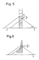
- FIG. 5 shows how, for a single reflection in the wafer, the variable pitch e between the mirrors of the wafer must be determined, at constant wafer width L. In this figure have been indicated the points Q and R which are the central points of the exit of the collimation optics and of the observation pupil, as they are seen from the wafer 6.
- a wafer for an optical assembly according to the invention can also be designed with a constant pitch and a variable wafer width, or even a variable number of reflections in the wafer.
- FIG. 6 is a diagram which illustrates such a variant. It should be noted that, in the embodiment according to FIG. 6; the side by which the light enters the wafer is not straight and that the side of the blade 5, which is in contact with the wafer and follows its shape, is also not straight.
- the wafer 5 according to FIGS. 2, 3 and 5, as well as the wafer according to FIG. 6, serves, as has been seen, to reconcentrate towards the observation pupil the rays coming from the collimation optics; it therefore has a completely different role from that of the wafer 3 according to FIG. 1 since this wafer 3 is used to create a second symmetrical image, the eye sometimes observing the direct image, for the bottom field, sometimes the indirect image, for the top field.
- the light coming from the collimating optics enters the blade 7 where it is reflected towards the eye by virtue of the flaps formed by the semi-reflecting mirrors 71, 72.
- these flaps also allow , to the observer, to see the external landscape located on the other side of the slide 7, so that the observer has, in his visual field, the external landscape with the collimated image superimposed.
- the present invention is not limited to the examples described or mentioned above; this is how, in particular, thicknesses, angles and shapes can be modified, depending on the conditions of use and the dimensions of the collimation optics.
- by performing a reflection on edge thanks to a mirror whose plane would be perpendicular to the plane of Figure 2 and would pass through the line segment EF drawn in this figure, it is possible to reduce the optical assembly described in l 'using Figures 2, all of its part located above this line segment.
Abstract
Description
La présente invention concerne un ensemble optique qui permet à un observateur de regarder simultanément ce qui se trouve normalement dans son champ visuel et une image collimatée, par introduction de cette image dans son champ visuel à l'aide d'une optique de combinaison comportant au moins un miroir semi-réfléchissant. Il est à noter que les termes "image collimatée" signifient, dans ce texte, image se formant à l'infini et que, le fait de fournir à l'observateur une image collimatée, lui évite d'avoir à accommoder de façons différentes et donc à se fatiguer la vue quand il fixe son attention sur le paysage et quand il la fixe sur l'image. L'invention concerne également des casques équipés de dispositifs optiques pour l'introduction d'une image dans le champ visuel d'un observateur.The present invention relates to an optical assembly which allows an observer to simultaneously view what is normally in his visual field and a collimated image, by introducing this image into his visual field using a combination optic comprising at minus a semi-reflecting mirror. It should be noted that the terms "collimated image" mean, in this text, an image forming at infinity and that, the fact of providing the observer with a collimated image, avoids him having to accommodate in different ways and so to tire your eyes when he fixes his attention on the landscape and when he fixes it on the image. The invention also relates to helmets equipped with optical devices for the introduction of an image into the visual field of an observer.
De tels dispositifs optiques existent ; ils sont, en particulier, utilisés en aéronautique pour fournir, par exemple, des informations de pilotage à un pilote sans qu'il ait à quitter des yeux le paysage.Such optical devices exist; they are, in particular, used in aeronautics to provide, for example, piloting information to a pilot without having to take his eyes off the landscape.
Ainsi la demande de brevet européen 0077 193 décrit un premier ensemble optique comportant un bloc de matériau transparent avec deux faces planes, parallèles, polies et une face d'entrée et, à l'intérieur de ce bloc, un miroir sphérique semi-réfléchissant. Ce bloc est réalisé de façon d'un rayon incident, provenant d'un générateur d'images, après avoir traversé la face d'entrée, subisse une réflexion totale sur une des deux faces parallèles puis une réflexion partielle sur le miroir semi-réfléchissant, puis une réfraction sur celle des deux faces parallèles sur laquelle il a déjà subi une réflexion totale. Les rayons lumineux provenant du paysage à observer, traversent le bloc optique par les deux faces parallèles et le miroir sphérique, avant d'atteindre l'oeil de l'observateur. Cet ensemble optique présente, en particulier, deux inconvénients : le bloc transparent est épais et, donc, lourd et encombrant et la face d'entrée constitue un masque qui réduit le champ visuel de l'observateur.Thus, European patent application 0077 193 describes a first optical assembly comprising a block of transparent material with two planar, parallel, polished faces and an entry face and, inside this block, a spherical semi-reflecting mirror. This block is produced in an incident ray, coming from an image generator, after having crossed the entry face, undergoes a total reflection on one of the two parallel faces then a partial reflection on the semi-reflecting mirror , then a refraction on that of the two parallel faces on which it has already undergone a total reflection. The light rays coming from the landscape to be observed, pass through the optical unit by the two parallel faces and the spherical mirror, before reaching the eye of the observer. This optical assembly has, in particular, two drawbacks: the transparent block is thick and therefore heavy and bulky and the entry face constitutes a mask which reduces the visual field of the observer.
Il est également connu, par la demande de brevet français 89 06721, d'utiliser un générateur d'images et une suite de miroirs semi-réfléchissants, parallèles, disposés dans un guide d'ondes optique et traités pour être réfléchissants sous des incidences de plus en plus faibles à mesure qu'ils sont plus éloignés du générateur. L'observateur regarde le paysage par transparence à travers les miroirs semi-réfléchissants. Ce deuxième ensemble optique, qui sera représenté à l'aide de la figure 1 ci-annexée, présente certains inconvénients et, plus particulièrement, une pupille d'injection de l'image dans l'optique de combinaison, d'une trentaine de millimètres de haut, donc trop grande, et des reflets parasites dus aux réflexions sur la tranche du guide d'ondes optique.It is also known, from French patent application 89 06721, to use an image generator and a series of semi-reflecting mirrors, parallel, arranged in an optical waveguide and treated to be reflective under incidences of more and more weak as they are further from the generator. The observer looks at the landscape through transparency through the semi-reflecting mirrors. This second optical assembly, which will be represented with the aid of FIG. 1 attached, has certain drawbacks and, more particularly, a pupil for injecting the image in the combination optics, of around thirty millimeters high, therefore too large, and parasitic reflections due to reflections on the edge of the optical waveguide.
Le but de la présente invention est d'éviter ou, pour le moins, de réduire les inconvénients de ces ensembles optiques connus.The object of the present invention is to avoid or, at the very least, to reduce the drawbacks of these known optical assemblies.
Ceci est obtenu avec un ensemble optique qui reprend sensiblement les éléments constitutifs du deuxième ensemble optique décrit ci-avant mais en combinant de façon différente et en modifiant la structure de l'un d'entre eux, de manière à lui faire jouer un rôle différent, tel que défini par la revendication 1.This is obtained with an optical assembly which substantially takes up the constituent elements of the second optical assembly described above but by combining differently and by modifying the structure of one of them, so as to make it play a different role. , as defined by
D'autres particularités et caractéristiques de l'invention apparaîtront à l'aide de la description ci-après et des figures s'y rapportant, qui représentent :
- la figure 1, un ensemble optique selon l'art connu,
- la figure 2, une vue de dessus d'un ensemble optique selon l'invention,
- les figures 3 et 4, des vues en coupe effectuées dans l'ensemble optique selon la figure 2,
- la figure 5, une vue de détail d'un des éléments constitutifs de l'ensemble selon la figure 2,
- la figure 6, une vue d'une variante de réalisation à l'élément selon la figure 5.
- FIG. 1, an optical assembly according to the known art,
- FIG. 2, a top view of an optical assembly according to the invention,
- FIGS. 3 and 4, sectional views taken in the optical assembly according to FIG. 2,
- FIG. 5, a detailed view of one of the constituent elements of the assembly according to FIG. 2,
- FIG. 6, a view of an alternative embodiment of the element according to FIG. 5.
La figure 1 montre, en vue de dessus schématique, un ensemble optique selon l'art antérieur, tel qu'il est placé pour rapport à un observateur, dont n'apparaît, sur la figure, que l'oeil gauche, V. Un autre ensemble semblable, destiné à l'oeil droit de l'observateur, n'a pas été dessiné sur la figure de même que n'a pas été représenté le casque que porte l'observateur et sur lequel sont fixés les deux ensembles optiques.Figure 1 shows, in schematic top view, an optical assembly according to the prior art, as it is placed in relation to an observer, of which appears, in the figure, only the left eye, V. A another similar assembly, intended for the observer's right eye, has not been drawn in the figure, as has not been shown the helmet worn by the observer and on which the two optical assemblies are fixed.
L'ensemble optique selon la figure 1 comporte un générateur d'images 1, muni d'un tube cathodique, une optique de collimation 2 pour mettre à l'infini l'image générée sur l'écran du tube cathodique, une galette de symétrisation, 3, faite d'un empilement à pas constant de miroirs rectangulaires tous de mêmes dimensions et une lame transparente 4 qui comporte des inclusions 40 à 44 dont l'une, 40, est à équidistance de deux grandes faces parallèles de la lame 4 et dont les autres, qui sont parallèles entre elles, et en biais par rapport aux deux grandes faces, sont appelées volets.The optical assembly according to FIG. 1 comprises an
Les volets 41 à 44 comportent chacune un miroir semi-réfléchissant et l'oeil, V, peut regarder simultanément le paysage par transparence à travers les volets 41 à 44 et l'image produite par le générateur d'images 1, par réflexion sur les volets 41 à 44. La lame 4 est une lame mince de section rectangulaire, à faces parallèles, dont les deux grandes faces sont inclinées à 15° par rapport à la verticale quand la tête de l'observateur n'est inclinée ni vers le haut ni vers le bas. Corrélativement l'axe optique de l'optique de collimation et du tube cathodique, qui sont dans le prolongement l'un de l'autre, sont inclinés de 15 degrés vers le haut ; de plus l'axe principal du guide d'ondes optique que constitue la lame 4 et l'axe optique de l'optique de collimation forment un angle de 135 degrés. Le fonctionnement de l'ensemble optique de la figure 1 peut être sommairement décrit comme suit : le générateur d'images, 1, fournit une image sur l'écran de son tube cathodique ; l'optique de collimation, 2, en forme une image à l'infini ; la galette de symétrisation, 3, qui est une optique d'équipartition, crée une image symétrique par rapport à un plan horizontal ; la première inclusion, 40, répartit uniformément les rayons d'un même champ sur les volets 41 à 44 ; les volets 41 à 44 réfléchissent sélectivement les différents champs pour former une pupille d'observation éloignée du dispositif et dans laquelle l'oeil de l'observateur pourra apercevoir à la fois l'image fournie par le générateur 1 et le paysage placé devant lui.The
Dans cet ensemble optique connu, la galette de symétrisation et l'utilisation de la réflexion sur la tranche de la lame 4 ou, plus précisément, sur la petite face latérale supérieure de la lame 4, permettent de réduire de moitié la hauteur de l'optique de collimation. Toutefois, comme il a été indiqué au début de ce document, cet ensemble optique présente des inconvénients que l'ensemble selon l'invention permet d'éviter ou, pour le moins, de réduire.In this known optical assembly, the symmetrization wafer and the use of the reflection on the edge of the blade 4 or, more precisely, on the small upper lateral face of the blade 4, make it possible to reduce the height of the collimation optics. However, as indicated at the beginning of this document, this optical assembly has drawbacks that the assembly according to the invention makes it possible to avoid or, at least, to reduce.
La figure 2 montre, vu du côté où est placé l'oeil d'un observateur, un ensemble optique pour l'introduction, en surimpression, d'une image dans le champ visuel d'un observateur. Sur la figure 2, deux traits d'axe, XX et YY, montrent les traces de deux plans de coupe correspondant à deux vues en coupe dessinées respectivement selon les figures 3 et 4.Figure 2 shows, seen from the side where the eye of an observer is placed, an optical assembly for the introduction, overprinted, of an image in the visual field of an observer. In FIG. 2, two axis lines, XX and YY, show the traces of two section planes corresponding to two section views drawn respectively according to FIGS. 3 and 4.
L'ensemble optique selon les figures 2, 3 et 4 comporte une première lame transparente 5, couplée optiquement à une seconde lame transparente 7 par une galette de concentration 6, formé par un empilement de miroirs réfléchissants, chaque miroir étant constitué par un rectangle de 8 sur 10 mm de côtés. La lame 5 comporte deux grandes faces parallèles 5a et 5b distantes de 8 mm ; la lame 7 comporte également deux grandes faces parallèles 7a et 7b qui sont respectivement dans les mêmes plans que les faces 5a et 5b.The optical assembly according to FIGS. 2, 3 and 4 comprises a first
Un tube cathodique, 1, représenté sur la figure 4, suivi d'une optique de collimation 2, également représentée sur la figure 4, fournissent une image collimatée, c'est-à-dire une image se formant à l'infini. Les rayons de cette image pénètrent dans la lame 5, par une extrémité C qui est inclinée à 55 degrés par rapport aux grandes faces 5a et 5b. La lame 5 comporte, à mi-distance de ses deux grandes faces, un miroir semi-réfléchissant 50.A cathode ray tube, 1, shown in Figure 4, followed by a
Les deux grandes faces parallèles de la lame 5 se présentent comme de pseudo-triangles rectangles dont un angle aigu est tronqué par une découpe droite correspondant à l'extrémité C qui sert d'accès pour l'image collimatée, et dont le côté opposé à cet angle tronqué forme une extrémité opposée à l'extrémité C et est accolé à l'un des côtés de la galette 6.The two large parallel faces of the
Les miroirs constituant la galette 6 ont leur face qui est perpendiculaire aux grandes faces de la lame 5 et au côté opposé à l'angle tronqué dans les pseudo-triangles des faces 5a, 5b. La lumière, qui provient de l'optique de collimation 2, traverse la galette 6 après un nombre impair de réflexions, comme il sera vu à l'aide de la figure 5, et pénètre alors dans la lame 7.The mirrors constituting the
Les deux grandes faces de la lame 7 se présentent, elles aussi, comme de pseudo-triangles rectangles, dont un angle aigu est tronqué par une découpe en arc de cercle et dont le côté opposé à l'angle tronqué correspond à une extrémité de la lame 7 accolée à la galette 6 ; c'est par cette extrémité que la lumière de l'image collimatée, après avoir traversé la lame 5 et la galette 6, pénètre dans la lame 7.The two large faces of the
Comme il apparaît sur les figures 2 et 3, ceux des bords de la lame 7, qui ne sont pas accolés à la galette, sont chanfreinés. Ainsi ces bords ne produisent pas un masque dans le champ visuel de l'oeil V, d'un observateur placé au niveau de la pupille d'observation P de l'ensemble optique. L'oeil V et la pupille d'observation sont dessinés sur la figure 3 ; ils se trouvent du côté de la face 7b, à environ 27 mm de cette face, à l'aplomb du centre des arcs de cercle qui tronquent les pseudo-triangles des faces 7a, 7b.As it appears in FIGS. 2 and 3, those of the edges of the
La lame 7 comporte deux volets 71, 72, constitués par des miroirs semi-réfléchissants, dont l'indice de réflexion est de 30 pour-cent ; ces volets sont inclinés à 27 degrés par rapport aux grandes faces 7a, 7b de la lame 7 et sont distants de 6,9 mm l'un de l'autre.The
Le fonctionnement des différentes parties de l'ensemble optique qui vient d'être décrit, est expliqué ci-après.The operation of the various parts of the optical assembly which has just been described is explained below.
La transmission lumineuse dans la lame 5 se fait avec réflexions totales sur les deux grandes faces 5a et 5b.The light transmission in the
Le miroir semi-réfléchissant 50 permet aux volets 71, 72 d'être touchés par tous les rayons, quelle que soit leur incidence, provenant du générateur d'images 1 à travers l'optique de collimation 2 ; ce miroir 50 a donc le même rôle que le miroir 40 selon la figure 1.The
La galette de concentration 6 sert à reconcentrer les rayons issus de l'optique de collimation vers la pupille d'observation P. Les rayons transmis par l'optique de collimation traversent la galette où ils subissent un nombre impair de réflexions avant de se diriger vers la pupille d'observation P. La figure 5 montre comment, pour une seule réflexion dans la galette, doit être déterminé, à largeur L de galette constante, le pas variable e entre les miroirs de la galette. Sur cette figure ont été indiqués les points Q et R qui sont les points centraux de la sortie de l'optique de collimation et de la pupille d'observation, tels qu'ils sont vus de la galette 6. La droite QR est perpendiculaire aux grandes dimensions de la galette 6 et, pour qu'il y ait une seule réflexion des rayons issus de M sur deux miroirs successifs M1, M2 de la galette, il faut que![]()
![]()
Il peut être intéressant de reconcentrer les rayons issus de l'optique de collimation en leur faisant subir un nombre impair, supérieur à un, de réflexions dans la galette 6, en effet cela permet de réduire le pas, e, entre les miroirs successifs quand il devient trop important et de réduire ainsi le diamètre de la pupille d'injection.It may be interesting to reconcentrate the rays from the collimation optics by subjecting them to an odd number, greater than one, of reflections in the
La formule précédente s'écrit alors, d'une façon plus générale :![]()
![]()
La liste du paragraphe suivant donne les valeurs de e dans l'exemple de réalisation selon les figures 2 à 5 ; il est à noter qu'à partir du douzième pas, le nombre de réflexions est de trois entre deux miroirs successifs alors qu'il était de un avant.The list in the following paragraph gives the values of e in the exemplary embodiment according to FIGS. 2 to 5; it should be noted that from the twelfth step, the number of reflections is three between two successive mirrors whereas it was one before.
Les couples de chiffres ci-après correspondent, pour le premier, au rang du pas compté à partir du pas le plus proche de la ligne PQ et, pour le second, à la valeur en milimètres de ce pas :The pairs of figures below correspond, for the first, to the rank of the step counted from the step closest to the line PQ and, for the second, to the value in millimeters of this step:
1-1 ; 2-1 ; 3-1 ; 4-1 ; 5-1 ; 6-1,05 ; 7-1,26 ; 8-1,51 ; 9-1,8 ; 10-2,16 ; 11-2,59 ; 12-1,04 ; 13-1,1 ; 14-1,17 ; 15-1,26 ; 16-1,33 ; 17-1,42 ; 18-1,52 ; 19-1,61 ; 20-1,72 ; 21-1,84 ; 22-1,95 ; 23-2,09 ; 24-2,22 ; 25-2,37 ; 26-2,52 ; 27-2,52 ; 28-2,52.1-1; 2-1; 3-1; 4-1; 5-1; 6-1.05; 7-1.26; 8-1.51; 9-1.8; 10-2.16; 11-2.59; 12-1.04; 13-1.1; 14-1.17; 15-1.26; 16-1.33; 17-1.42; 18-1.52; 19-1.61; 20-1.72; 21-1.84; 22-1.95; 23-2.09; 24-2.22; 25-2.37; 26-2.52; 27-2.52; 28-2.52.
Dans la formule![]()
![]()
Une galette pour un ensemble optique selon l'invention peut également être conçue avec un pas constant et une largeur de galette variable, voire un nombre de réflexions variable dans la galette. La figure 6 est un schéma qui illustre une telle variante. Il est à noter que, dans la réalisation selon la figure 6; le côté par lequel la lumière pénètre dans la galette n'est pas droit et que le côté de la lame 5, qui est en contact avec la galette et en épouse la forme, n'est, non plus, pas droit.A wafer for an optical assembly according to the invention can also be designed with a constant pitch and a variable wafer width, or even a variable number of reflections in the wafer. FIG. 6 is a diagram which illustrates such a variant. It should be noted that, in the embodiment according to FIG. 6; the side by which the light enters the wafer is not straight and that the side of the
La galette 5 selon les figures 2, 3 et 5, de même que la galette selon la figure 6, sert, comme il a été vu, à reconcentrer vers la pupille d'observation les rayons provenant de l'optique de collimation ; elle a donc un rôle totalement différent de celui de la galette 3 selon la figure 1 puisque cette galette 3 sert, elle, à créer une deuxième image symétrisée, l'oeil observant tantôt l'image directe, pour le champ du bas, tantôt l'image indirecte, pour le champ du haut.The
Après avoir traversé la galette 6, la lumière provenant de l'optique de collimation pénètre dans la lame 7 où elle est réfléchie vers l'oeil grâce aux volets constitués par les miroirs semi-réfléchissants 71, 72. Par transmission, ces volets permettent également, à l'observateur, de voir le paysage extérieur situé de l'autre côté de la lame 7, si bien que l'observateur a, dans son champ visuel, le paysage extérieur avec l'image collimatée en surimpression.After passing through the
L'ensemble optique décrit à l'aide des figures 2 et suivantes, de par ses dimensions réduites, ne nécessite que deux miroirs semi- réfléchissants de combinaison 71, 72, dans la lame 7 ; de ce fait les miroirs 71, 72 n'ont pas besoin d'être traités pour être sélectifs en incidence comme c'est le cas pour la réalisation selon la figure 1 où les pertes de lumière sur les volets successifs feraient que, sans un tel traitement, l'image vue par l'oeil et provenant de l'optique de collimation serait très nettement plus lumineuse dans sa partie fournie par le volet 41 que dans sa partie fournie pour le volet 44.The optical assembly described with the aid of FIGS. 2 and following, by virtue of its reduced dimensions, only requires two semi-reflecting combination mirrors 71, 72, in the
La présente invention n'est pas limitée aux exemples décrits ou mentionnés ci-avant ; c'est ainsi, en particulier, que les épaisseurs, les angles et les formes peuvent être modifiés, en fonction des conditions d'utilisation et des dimensions de l'optique de collimation. De plus, en effectuant une réflexion sur tranche, grâce à un miroir dont le plan serait perpendiculaire au plan de la figure 2 et passerait par le segment de droite EF dessiné sur cette figure, il est possible de réduire l'ensemble optique décrit à l'aide des figures 2, de toute sa partie située au-dessus de ce segment de droite.The present invention is not limited to the examples described or mentioned above; this is how, in particular, thicknesses, angles and shapes can be modified, depending on the conditions of use and the dimensions of the collimation optics. In addition, by performing a reflection on edge, thanks to a mirror whose plane would be perpendicular to the plane of Figure 2 and would pass through the line segment EF drawn in this figure, it is possible to reduce the optical assembly described in l 'using Figures 2, all of its part located above this line segment.
Claims (4)
Applications Claiming Priority (2)
| Application Number | Priority Date | Filing Date | Title |
|---|---|---|---|
| FR9006656 | 1990-05-29 | ||
| FR9006656A FR2662821B1 (en) | 1990-05-29 | 1990-05-29 | OPTICAL ASSEMBLY FOR THE INTRODUCTION, IN SUPERIMPRESSION, OF AN IMAGE INTO THE VISUAL FIELD OF AN OBSERVER AND HELMET COMPRISING AT LEAST ONE SUCH ASSEMBLY. |
Publications (2)
| Publication Number | Publication Date |
|---|---|
| EP0459850A1 true EP0459850A1 (en) | 1991-12-04 |
| EP0459850B1 EP0459850B1 (en) | 1994-12-21 |
Family
ID=9397046
Family Applications (1)
| Application Number | Title | Priority Date | Filing Date |
|---|---|---|---|
| EP91401210A Expired - Lifetime EP0459850B1 (en) | 1990-05-29 | 1991-05-07 | Head-up display and helmet comprising at least one such display |
Country Status (7)
| Country | Link |
|---|---|
| US (1) | US5153774A (en) |
| EP (1) | EP0459850B1 (en) |
| JP (1) | JP2926643B2 (en) |
| CA (1) | CA2043371A1 (en) |
| DE (1) | DE69106053T2 (en) |
| ES (1) | ES2065633T3 (en) |
| FR (1) | FR2662821B1 (en) |
Cited By (2)
| Publication number | Priority date | Publication date | Assignee | Title |
|---|---|---|---|---|
| FR2816414A1 (en) * | 2000-11-03 | 2002-05-10 | Thomson Csf | DOUBLE WINDOW COMBINER FOR HIGH HEAD SIGHT |
| WO2007031986A2 (en) | 2005-09-12 | 2007-03-22 | Elbit Systems Ltd. | Near eye display system |
Families Citing this family (6)
| Publication number | Priority date | Publication date | Assignee | Title |
|---|---|---|---|---|
| FR2709854B1 (en) * | 1993-09-07 | 1995-10-06 | Sextant Avionique | Visualization device with optimized colors. |
| CN1114382C (en) * | 1998-01-02 | 2003-07-16 | 王振民 | Optical instrument for pointing out position of focus in brain |
| IL148804A (en) * | 2002-03-21 | 2007-02-11 | Yaacov Amitai | Optical device |
| ITTO20020625A1 (en) * | 2002-07-17 | 2004-01-19 | Fiat Ricerche | LIGHT GUIDE FOR "HEAD-MOUNTED" OR "HEAD-UP" TYPE DISPLAY DEVICES |
| WO2009117870A1 (en) * | 2008-03-26 | 2009-10-01 | 深圳航天科技创新研究院 | Spectacles type display device using single display chip |
| FR2999301B1 (en) * | 2012-12-12 | 2015-01-09 | Thales Sa | OPTICAL GUIDE OF COLLIMATE IMAGES WITH OPTICAL BEAM DEDOLDER AND OPTICAL DEVICE THEREFOR |
Citations (2)
| Publication number | Priority date | Publication date | Assignee | Title |
|---|---|---|---|---|
| DE3032849A1 (en) * | 1980-09-01 | 1982-04-08 | Karl 8000 München Speidel | Ring concentrator used as refractor objective - has large aperture and focuses parallel light on common point at back intersection on axis |
| EP0129821A2 (en) * | 1983-06-24 | 1985-01-02 | Kei Mori | Chlorella nurturing device |
Family Cites Families (1)
| Publication number | Priority date | Publication date | Assignee | Title |
|---|---|---|---|---|
| US4099841A (en) * | 1976-06-30 | 1978-07-11 | Elliott Brothers (London) Limited | Head up displays using optical combiner with three or more partially reflective films |
-
1990
- 1990-05-29 FR FR9006656A patent/FR2662821B1/en not_active Expired - Lifetime
-
1991
- 1991-05-07 EP EP91401210A patent/EP0459850B1/en not_active Expired - Lifetime
- 1991-05-07 DE DE69106053T patent/DE69106053T2/en not_active Expired - Fee Related
- 1991-05-07 ES ES91401210T patent/ES2065633T3/en not_active Expired - Lifetime
- 1991-05-28 JP JP3152439A patent/JP2926643B2/en not_active Expired - Lifetime
- 1991-05-28 CA CA002043371A patent/CA2043371A1/en not_active Abandoned
- 1991-05-29 US US07/706,342 patent/US5153774A/en not_active Expired - Fee Related
Patent Citations (2)
| Publication number | Priority date | Publication date | Assignee | Title |
|---|---|---|---|---|
| DE3032849A1 (en) * | 1980-09-01 | 1982-04-08 | Karl 8000 München Speidel | Ring concentrator used as refractor objective - has large aperture and focuses parallel light on common point at back intersection on axis |
| EP0129821A2 (en) * | 1983-06-24 | 1985-01-02 | Kei Mori | Chlorella nurturing device |
Cited By (6)
| Publication number | Priority date | Publication date | Assignee | Title |
|---|---|---|---|---|
| FR2816414A1 (en) * | 2000-11-03 | 2002-05-10 | Thomson Csf | DOUBLE WINDOW COMBINER FOR HIGH HEAD SIGHT |
| WO2002037167A1 (en) * | 2000-11-03 | 2002-05-10 | Thales | Double-mirror combining glass for head-up display |
| US6751025B2 (en) | 2000-11-03 | 2004-06-15 | Thales | Double-mirror combining glass for head-up display |
| WO2007031986A2 (en) | 2005-09-12 | 2007-03-22 | Elbit Systems Ltd. | Near eye display system |
| WO2007031986A3 (en) * | 2005-09-12 | 2007-05-31 | Elbit Systems Ltd | Near eye display system |
| US8079713B2 (en) | 2005-09-12 | 2011-12-20 | Elbit Systems Ltd. | Near eye display system |
Also Published As
| Publication number | Publication date |
|---|---|
| DE69106053D1 (en) | 1995-02-02 |
| CA2043371A1 (en) | 1991-11-30 |
| DE69106053T2 (en) | 1995-05-11 |
| US5153774A (en) | 1992-10-06 |
| ES2065633T3 (en) | 1995-02-16 |
| JPH0667116A (en) | 1994-03-11 |
| EP0459850B1 (en) | 1994-12-21 |
| FR2662821B1 (en) | 1992-08-07 |
| JP2926643B2 (en) | 1999-07-28 |
| FR2662821A1 (en) | 1991-12-06 |
Similar Documents
| Publication | Publication Date | Title |
|---|---|---|
| EP0399865B1 (en) | Optical device for introduction of a collimated image into the field of view of an observer and helmet comprising such a device | |
| EP0365406B1 (en) | Optical collimating system for a helmet visual | |
| CA2018204C (en) | Wide field ergonomic helmet sight visualization device | |
| EP0240374B1 (en) | Head-up display and its use in a helmet-mounted sighting instrument | |
| EP0286496B1 (en) | Helmet-mounted, binocular, holographic view finder with wide field of vision | |
| EP3074809B1 (en) | Device for extending the exit pupil and head up display comprising said device | |
| EP0119128B1 (en) | Head-up display | |
| EP1019775B1 (en) | Optical device for helmet visor comprising a mangin mirror | |
| EP3215884B1 (en) | Head-mounted display with crossed optics | |
| FR2999301A1 (en) | OPTICAL GUIDE OF COLLIMATE IMAGES WITH OPTICAL BEAM DEDOLDER AND OPTICAL DEVICE THEREFOR | |
| FR2638242A1 (en) | Optical collimation system, especially for a helmet display | |
| CA2023983A1 (en) | Microscope-endoscope combination useful particularly in surgery | |
| EP0459850B1 (en) | Head-up display and helmet comprising at least one such display | |
| EP3329317B1 (en) | Compact head-up display device | |
| FR2569867A1 (en) | OPTICAL PROJECTOR FOR PILOT COLLIMATOR | |
| EP0314243B1 (en) | Device for compensating the total distortion caused by the shape of a transparent wall | |
| EP1057069A1 (en) | Optical device for pilot's visor comprising a tubular mirror | |
| FR2693004A1 (en) | Optical collimator for visor of protective helmet etc. - comprises sequence of linear polariser, spherical mirror, slide and flat mirror, with reflection of mirrors controlled by surface coatings | |
| EP0111351A1 (en) | Biocular eyepiece | |
| EP0225818B1 (en) | Episcope incorporating a spectating system | |
| EP1067639A1 (en) | Unstable laser resonator | |
| FR2706636A1 (en) | Binocular optical device with resolution and / or increased field of view, especially for night vision. | |
| FR2644249A1 (en) | Optical collimation system, in particular for a helmet display | |
| FR2922322A1 (en) | OPTICAL DEVICE FOR NIGHT VISION WITH STANDARD LIGHT INTENSIFIER | |
| FR2702283A1 (en) | Oscillating mirror bezel for infrared vision. |
Legal Events
| Date | Code | Title | Description |
|---|---|---|---|
| PUAI | Public reference made under article 153(3) epc to a published international application that has entered the european phase |
Free format text: ORIGINAL CODE: 0009012 |
|
| AK | Designated contracting states |
Kind code of ref document: A1 Designated state(s): BE DE ES FR GB IT NL SE |
|
| 17P | Request for examination filed |
Effective date: 19920526 |
|
| 17Q | First examination report despatched |
Effective date: 19940329 |
|
| GRAA | (expected) grant |
Free format text: ORIGINAL CODE: 0009210 |
|
| AK | Designated contracting states |
Kind code of ref document: B1 Designated state(s): BE DE ES FR GB IT NL SE |
|
| ITF | It: translation for a ep patent filed |
Owner name: JACOBACCI CASETTA & PERANI S.P.A. |
|
| REF | Corresponds to: |
Ref document number: 69106053 Country of ref document: DE Date of ref document: 19950202 |
|
| REG | Reference to a national code |
Ref country code: ES Ref legal event code: FG2A Ref document number: 2065633 Country of ref document: ES Kind code of ref document: T3 |
|
| GBT | Gb: translation of ep patent filed (gb section 77(6)(a)/1977) |
Effective date: 19950208 |
|
| PLBE | No opposition filed within time limit |
Free format text: ORIGINAL CODE: 0009261 |
|
| STAA | Information on the status of an ep patent application or granted ep patent |
Free format text: STATUS: NO OPPOSITION FILED WITHIN TIME LIMIT |
|
| 26N | No opposition filed | ||
| PGFP | Annual fee paid to national office [announced via postgrant information from national office to epo] |
Ref country code: DE Payment date: 19990417 Year of fee payment: 9 |
|
| PGFP | Annual fee paid to national office [announced via postgrant information from national office to epo] |
Ref country code: GB Payment date: 19990421 Year of fee payment: 9 |
|
| PGFP | Annual fee paid to national office [announced via postgrant information from national office to epo] |
Ref country code: NL Payment date: 19990422 Year of fee payment: 9 |
|
| PGFP | Annual fee paid to national office [announced via postgrant information from national office to epo] |
Ref country code: BE Payment date: 19990511 Year of fee payment: 9 |
|
| PGFP | Annual fee paid to national office [announced via postgrant information from national office to epo] |
Ref country code: SE Payment date: 19990514 Year of fee payment: 9 |
|
| PGFP | Annual fee paid to national office [announced via postgrant information from national office to epo] |
Ref country code: FR Payment date: 19990521 Year of fee payment: 9 |
|
| PGFP | Annual fee paid to national office [announced via postgrant information from national office to epo] |
Ref country code: ES Payment date: 19990524 Year of fee payment: 9 |
|
| PG25 | Lapsed in a contracting state [announced via postgrant information from national office to epo] |
Ref country code: GB Free format text: LAPSE BECAUSE OF NON-PAYMENT OF DUE FEES Effective date: 20000507 |
|
| PG25 | Lapsed in a contracting state [announced via postgrant information from national office to epo] |
Ref country code: SE Free format text: LAPSE BECAUSE OF NON-PAYMENT OF DUE FEES Effective date: 20000508 Ref country code: ES Free format text: THE PATENT HAS BEEN ANNULLED BY A DECISION OF A NATIONAL AUTHORITY Effective date: 20000508 |
|
| PG25 | Lapsed in a contracting state [announced via postgrant information from national office to epo] |
Ref country code: BE Free format text: LAPSE BECAUSE OF NON-PAYMENT OF DUE FEES Effective date: 20000531 |
|
| BERE | Be: lapsed |
Owner name: SEXTANT AVIONIQUE Effective date: 20000531 |
|
| PG25 | Lapsed in a contracting state [announced via postgrant information from national office to epo] |
Ref country code: NL Free format text: LAPSE BECAUSE OF NON-PAYMENT OF DUE FEES Effective date: 20001201 |
|
| GBPC | Gb: european patent ceased through non-payment of renewal fee |
Effective date: 20000507 |
|
| EUG | Se: european patent has lapsed |
Ref document number: 91401210.9 |
|
| PG25 | Lapsed in a contracting state [announced via postgrant information from national office to epo] |
Ref country code: FR Free format text: LAPSE BECAUSE OF NON-PAYMENT OF DUE FEES Effective date: 20010131 |
|
| NLV4 | Nl: lapsed or anulled due to non-payment of the annual fee |
Effective date: 20001201 |
|
| PG25 | Lapsed in a contracting state [announced via postgrant information from national office to epo] |
Ref country code: DE Free format text: LAPSE BECAUSE OF NON-PAYMENT OF DUE FEES Effective date: 20010301 |
|
| REG | Reference to a national code |
Ref country code: FR Ref legal event code: ST |
|
| REG | Reference to a national code |
Ref country code: ES Ref legal event code: FD2A Effective date: 20020204 |
|
| PG25 | Lapsed in a contracting state [announced via postgrant information from national office to epo] |
Ref country code: IT Free format text: LAPSE BECAUSE OF NON-PAYMENT OF DUE FEES Effective date: 20050507 |