EP0241229A2 - A fast assignment technique for use in a switching arrangement - Google Patents
A fast assignment technique for use in a switching arrangement Download PDFInfo
- Publication number
- EP0241229A2 EP0241229A2 EP87302893A EP87302893A EP0241229A2 EP 0241229 A2 EP0241229 A2 EP 0241229A2 EP 87302893 A EP87302893 A EP 87302893A EP 87302893 A EP87302893 A EP 87302893A EP 0241229 A2 EP0241229 A2 EP 0241229A2
- Authority
- EP
- European Patent Office
- Prior art keywords
- packets
- separate
- input
- arrangement
- output
- Prior art date
- Legal status (The legal status is an assumption and is not a legal conclusion. Google has not performed a legal analysis and makes no representation as to the accuracy of the status listed.)
- Granted
Links
Images


Classifications
-
- H—ELECTRICITY
- H04—ELECTRIC COMMUNICATION TECHNIQUE
- H04L—TRANSMISSION OF DIGITAL INFORMATION, e.g. TELEGRAPHIC COMMUNICATION
- H04L12/00—Data switching networks
- H04L12/54—Store-and-forward switching systems
-
- H—ELECTRICITY
- H04—ELECTRIC COMMUNICATION TECHNIQUE
- H04Q—SELECTING
- H04Q11/00—Selecting arrangements for multiplex systems
-
- H—ELECTRICITY
- H04—ELECTRIC COMMUNICATION TECHNIQUE
- H04B—TRANSMISSION
- H04B7/00—Radio transmission systems, i.e. using radiation field
- H04B7/14—Relay systems
- H04B7/15—Active relay systems
- H04B7/204—Multiple access
- H04B7/2045—SS-FDMA, FDMA satellite switching
Definitions
- the present invention relates to a fast packet assignment technique for use in, for example, a time-division-multiple-access (TDMA) or a frequency-division-multiple-access (FDMA) multi-port switching arrangement. More particularly, for a TDMA switching arrangement, the total traffic from and to each of N remote service areas, regardless of destination or origination, is totaled to provide 2 overall traffic vectors (inbound and outbound). M concurrent transmission assignments are made from each overall traffic vector for each time slot period of a TDMA frame by extracting M non-zero elements from the elements of each overall vector, where M ⁇ N, to effectively provide a global time slot interchange arrangement where more than one element from a service area can be concurrently transmitted to two separate service areas.
- TDMA time-division-multiple-access
- FDMA frequency-division-multiple-access
- All of the above techniques and switching arrangements use a technique or algorithm which assigns messages through the switching arrangement using elements within a two-dimensional matrix.
- a technique or algorithm which assigns messages through the switching arrangement using elements within a two-dimensional matrix.
- the problem remaining in the prior art is to provide a fast assignment technique, and a TDMA or FDMA multi-port switching arrangement for implementing such technique, that approximates a global time slot or channel interchange arrangement by not using a technique that confines itself primarily to extracting single messages or packets from any of the individual non-zero elements associated with any service area within a two-dimensional traffic matrix for assignment of transmissions through the switching arrangement.
- the problem in the prior art has been solved in accordance with the present invention which relates to (a) a fast assignment technique and (b) a multi-port switching arrangement capable of implementing such fast assignment technique which is disposed in, for example, a base station of a time-division-multiple-access (TDMA) or frequency-division-multiple-access (FDMA) system.
- TDMA time-division-multiple-access
- FDMA frequency-division-multiple-access
- an assignment of M packet or message units from the N traffic elements to the paths through the M ⁇ M switch during each time slot period is made by extracting M non-zero elements from the totaled vector to effectively provide a global time slot or channel interchange arrangement within the M ⁇ M switch.
- M non-zero elements selected from the N vector elements one or more packet or message unit associated with a particular one of the N areas can be arbitrarily assigned from a vector total for concurrent transmission through the M ⁇ M switch to two different service areas.
- a second group of C information packets from each of the M input ports is stored in separate second storage locations.
- the first group of C information packets from each of the M input ports is directed out of the first storage locations in a parallel manner at any instant of time such that no more than M information packets are concurrently transferred into M separate predetermined output lines, one associated with each of M output ports for transmission to remote service areas.
- the no more than M information packets concurrently transferred can comprise at least two information packets from any one of the M input ports.
- FIG. l is a block diagram of an exemplary M ⁇ M switching arrangement in accordance with the present invention which implements a fast assignment technique or algorithm which will be discussed in detail hereinafter.
- FIG. 2 is a block diagram of an exemplary switching hierarchy as might be found in, for example, a central base station of a multiple beam radio communication system which is capable of blanketing a service region with a contiguous raster of narrow beams for providing wideband interconnections among remote stations or service areas dispersed over a geographical area.
- the centrally located base station of FIG. 2 will be considered hereinafter as being capable of communicating with the remote stations or areas using the well-known Time-Division-Multiple-Access (TDMA) technique.
- TDMA Time-Division-Multiple-Access
- each beam position associated with a particular separate remote station or service area is served by two dedicated feedhorns, one to receive and one to transmit, with different frequencies used for each to reduce interference.
- the plurality of N receive feedhorns are designated l01 to l0 N and the corresponding plurality of N transmit feedhorns are designated ll1 to ll N .
- the relatively large number N of feedhorns are arranged, for example, in equal-sized groups of P feedhorns, and each group of P receiving and transmitting feedhorns l0 and ll is connected to a smaller number (Q) of one or more receivers l2 and transmitters l3, respectively, via a separate respective P ⁇ Q receive antenna port switch l4 and Q ⁇ P transmit antenna port switch l5.
- the receive and transmit antenna port switches l4 and l5 are physically distinct and operate independently under the control of a Network Controller l8 and, for purposes of explanation hereinafter, each port switch supports the same number of P feedhorns.
- each receiver l2 demodulates the received signal to baseband and regenerates it, while each transmitter l3 modulates the digital data stream onto the carrier.
- the number of Q receivers l2 and Q transmitters l3 assigned to an associated group of P receiver feedhorns l0 and P transmitter feedhorns ll, respectively, and associated with a particular respective receive antenna port switch l4 or transmit antenna port switch l5, is proportional to the total amount of traffic presented by the beam positions served by the associated group of feedhorns.
- a group of P feedhorns serving lightly loaded beams is assigned only one transmitter/receiver pair while a group of P feedhorns presenting a factor of K greater traffic than the lightly loaded group is assigned K transmitter/receiver pairs where K is equal to or less than P.
- the receivers l2 and transmitters l3 provide a TDMA mode of service such that remote stations in the various beams are connected via the port switches l4 and l5, respectively, to the associated receivers l2 and transmitters l3 in a repetitive time division manner.
- each repetitive TDMA frame provides C time slots, and there is one such frame associated with each transmitter/receiver l3/l2 pair.
- the number of time slots allocated to each user at a remote station is dependent upon the traffic demand of that user, up to the full transceiver capacity C.
- the present central station can also be used as a central station for a plurality of N terrestrial wire lines or some combination of radio and wire line terminations that do not exceed N.
- feedhorns l0 and ll would not be required and the wire lines can be terminated directly on the corresponding terminals of the receive and transmit port switches l5 and l4, respectively.
- FIG. 1 For purposes of illustration, it will be assumed that there are a plurality of M transmitter/receiver l3/l2 pairs. These transmitter/receiver pairs are interconnected with one another by means of an M ⁇ M centrally located time division switching means l6.
- the present central station can also be used as a central station for a plurality of N terrestrial wire lines or some combination of radio and wire line terminations that do not exceed N.
- feedhorns l0 and ll would not be required and the wire lines can be terminated directly on the corresponding terminals of the receive and transmit port switches l5 and l4, respectively.
- wire lines l7 can be terminated on central switching means l6.
- No more than a full compliment of M 50 Mb/s ports can be provided on central switching means l6, with each wire line l7 input port being a properly formatted terrestrial wire line so that the wire lines appear to central switching means l6 as an additional transmitter/receiver pair.
- each TDMA time slot corresponds to some fixed rate one-way connection between two remote stations.
- the traffic among N beam positions can be represented by a traffic matrix T : where t i,j represents the traffic, in time slots, arising within beam i and destined for beam j.
- the elements of matrix T may vary with time as the beam-to-beam connection patterns change.
- Equation (2) defines that the total traffic arising in beam position i cannot exceed the number of time slots C within one frame.
- Equation (3) defines that the total traffic into beam j cannot exceed the number of time slots in one frame.
- equation (4) defines that the total traffic cannot exceed the total capacity of all M transmitter/receiver pairs.
- equations (2) to (4) are sufficient conditions guaranteeing the existence of a nonconflicting TDMA assignment to the M transmitter/receiver pairs.
- T can be represented as the sum of C N ⁇ N matrices, each having M non-zero elements all equal to unity with no non-zero element sharing the same row or column with any other.
- the M non-zero elements in each such N ⁇ N matrix correspond to the M beam pairs that may be interconnected by the M transmitter/receiver pairs in any time slot of the frame.
- traffic matrix T additional constraints are imposed upon traffic matrix T , namely, that the sum of the traffic presented by any group of beams cannot exceed the capacity, in time slots, of the specific number of transmitter/receiver pairs assigned to that group. Any resulting TDMA assignment must assure that in every time slot, each group must nonconflictingly transmit and receive a number of times equal to the number of transmitter/receiver pairs allocated to that group, which to date has not been shown to be possible. Secondly, even without these additional constraints, the actual process of assigning from the matrix is a very difficult task, and the technique's execution time would limit the ability to rapidly update the assignment in response to changing traffic patterns.
- the present arrangement does not instantaneously discharge packets of information arriving in given time slots of the incoming frames into the same time slots of the outgoing frames. Rather, the packets arriving in any one frame are temporarily stored for subsequent transmission in the next frame. With such technique, it is also permissible to rearrange the time slot assignments of the various packets. More particularly, in accordance with the present technique, users are assigned in a nonconflicting manner to the TDMA frames inbound to the central base station, storing these arriving packets in memory as they arrive. These stored packets are then assigned for nonconflicting retransmission in the next frame interval of the outbound frames in a manner which also promotes minimal interference by scheduling packets for interfering stations in different time slots of a frame period. These inbound and outbound frame assignments are repetitive until updated as mandated by changing traffic patterns.
- Equation (7) is an expression of the fact that the total traffic offered by the P beams in group g cannot exceed the capacity of the K g receivers assigned to group g.
- Equation (7) is satisfied with equality, since it is always possible to add dummy traffic without violating equations (2) or (4), then there always exists at least K g non-zero elements of R belonging to group g, and not more than K g elements of R belonging to group g may equal C exactly. It can then be said that it is possible to assign traffic from R to the M receivers.
- K g elements including all those summing to C exactly.
- One unit of traffic may be removed from each element selected; the M units so removed, arising in different beams, may be assigned in a nonconflicting manner to the first time slot of the M inbound frames such that K g units are assigned to the K g receivers serving the group g.
- the remaining elements in R have the property that no element exceeds C-l, the sum of the elements for group g equals K g (C-l), and all elements sum to M(C-l). Furthermore, there remain C-l unassigned time slots in each inbound frame.
- FIGs. 4 and 5 An exemplary reduction of the vector R and the resulting assignment is shown in FIGs. 4 and 5, with beams numbered sequentially from top to bottom.
- FIG. 5 shows the resulting frame assignments with the number shown in each time slot of a frame corresponding to the beam assigned to transmit in that time slot.
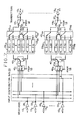
- FIG. l shows an exemplary hardware architecture of the M ⁇ M switching means l6 of FIG. 2 in accordance with the present invention for switching baseband digital signals.
- Each of the M input ports 201 to 20 M accepts a continuous sequence of packets from receivers l21 to l2 M , respectively, at the full transmission rate, e.g., 50 Mb/sec.
- the packet sequence is shown as being routed through a single pole/double throw (SP/DT) switching means 2l1 which alternates between its two positions at the TDMA frame rate. More particularly, switching means 2l1 stays in one fixed position throughout a full TDMA frame period and then switches to its alternate position for the next full frame period.
- SP/DT single pole/double throw
- switching means 2l1 is in the upper position as shown in FIG. l, and all packets are passed to the input of second switching means 22 1A .
- second switching means 22 1A is driven by the TDMA time-slot clock so that successive packets are loaded into memories labeled Z ij of memory module 23 iA , where i designates the input port (l-M) and j varies from l to C representative of the total number of packets, or time slots, in a TDMA frame.
- Each memory Z ij of memory module 23 holds a packet from a specific remote station destined for another remote station.
- This operation goes on simultaneously for each of the M parallel inputs 201 to 20 M resulting in all the incoming data packets being stored in the memories Z ij of memory module 23 iA .
- the memory loading operation into memory modules 23 iA is complete and switches 2l1 to 2l M are switched to the alternate position to cause the packets from the next frame period to be written into the memories Z ij of memory modules 23 iB .
- third switching means 241 to 24 M which are in the upward position as shown in FIG. l, and to C:M switches 251 to 25 M , respectively.
- C:M switches 25 i are driven at the TDMA time-slot clock rate.
- the function of third switching means 24 i is simply to select either one of memory modules 23 iA or 23 iB in alternating TDMA frames, and C:M switches 25 i function to route the packets to their proper output port 271 to 27 M and the associated transmitter l3 in a predetermined sequence via an output distribution bus 26.
- Both the storage of inbound packets and the distribution of outbound packets are under the control of a network controller l8 shown in FIG. 2 which can use, for example, clock signals and a table look-up capability for achieving the switching functions as is well known in the art.
- the output distribution bus 26 is functionally shown as a bus of M parallel wires with each wire terminating in a separate one of the M transmitters l3. For example, if a packet in memory Z12 in memory module 23 1A is scheduled to go to transmitter l33 in a particular time slot, this memory location will be connected by C:M switch 251 to wire 3 of bus 26 terminating in transmitter l33 during the proper time slot.
- C:M switches 251 to 25 M can direct up to M packets onto separate wires of bus 26 in each time slot from anywhere the memories Z ij , and these packets are always distributed among the M wires of bus 26 without any collision.
- C packets from each memory module 23 are concurrently available at the C inputs of the associated C:M switch 25 i , such switch can direct one or more packets onto separate wires of bus 26 during any time slot period if the N ⁇ N traffic matrix reduction indicated such assignment.
- FIG. l shows a wired-OR arrangement whereby for each output wire terminating in a specific transmitter l3 there are exactly M input wires connected to it, each from a different C:M switch 25.
- M is practical for M not larger than, for example, 8.
- 8 lines from 8 different switches 25 must be grouped in a wired-OR manner and then l6 of these groups are combined with an OR gate 30 to accomplish the required function as shown in FIG. 6.
- M identical sets of the arrangement of FIG. 6 would complete the entire bus 26.
- Each of the M received data streams is connected to a separate wire of bus 26 and the M wires together carry all the M-channel data simultaneously.
- Network Controller l8 makes the incoming and outgoing traffic assignments, it assigns a memory location to each incoming packet in such a way that the desired outbound transmissions can be obtained by sequentially reading out the contents of each memory location Z ij in each memory module 23. More particularly, for transmitter l31, the M packets in each time slot are concurrently received at the M inputs to an M:C switch 401.
- M:C switch 401 functions to direct the correct packet(s) in each time slot from bus 26 to the output bus 4l1 and through switching means 421 for storage in the appropriate memory location Z ij of memory module 23 1A .
- switching means 421 moves to its alternate position to load memories Z ij of memory module 23 1B .
- switch 43 1A functions to deliver the packets stored in memory locations Z11 to Z 1C in a predetermined order for transmission to transmitter l31 via single pole-double throw switching means 441. It is to be understood that the operation of switches 40, 42, 43 and 44, and memory modules 23, is under the control of Network Controller l8 in the manner indicated for the components of FIG. l.
- second switching means 22 i could be a channel dropping filter which directs each of C concurrently received channels in separate frequency bands into a separate one of the C memories in each associated memory module 23 dependent on the position of switching means 2l.
- Distribution bus 26 would contain M buses, each containing C wires which carry the C separate frequency band channels associated with a transmitter l3.
- Switch 25 would then comprise a C:CM switch to direct each of the l-C packets onto the proper l-C wires, respectively, associated with the M buses of distribution bus 26 so that each packet is delivered to the appropriate transmitter l3 for modulation with the appropriate carrier.
Abstract
Description
- The present invention relates to a fast packet assignment technique for use in, for example, a time-division-multiple-access (TDMA) or a frequency-division-multiple-access (FDMA) multi-port switching arrangement. More particularly, for a TDMA switching arrangement, the total traffic from and to each of N remote service areas, regardless of destination or origination, is totaled to provide 2 overall traffic vectors (inbound and outbound). M concurrent transmission assignments are made from each overall traffic vector for each time slot period of a TDMA frame by extracting M non-zero elements from the elements of each overall vector, where M<N, to effectively provide a global time slot interchange arrangement where more than one element from a service area can be concurrently transmitted to two separate service areas.
- Various techniques or algorithms have been used with specifically designed switching arrangements to direct TDMA incoming messages to the appropriate outputs of the associated switching arrangement. In this regard, see, for example, U. S. patents 4,232,266 and 4,38l,562 issued to A. Acampora on November 4, l980, and April 26, l983, respectively, and the article by G. Bongiovanni et al. in the IBM Technical Disclosure Bulletin, Vol. 26, No. 8, January l984, at pages 4344-4348. A typical time-space-time switching arrangement for directing multiple packets of information through a switch is disclosed, for example, in U. S.
patent 4,5l2,0l2 issued to T. Sampei et al. on April l6, l985. All of the above techniques and switching arrangements use a technique or algorithm which assigns messages through the switching arrangement using elements within a two-dimensional matrix. With such techniques or algorithms, only one message unit or packet associated with any non-zero element of a service area in the two-dimensional traffic matrix is directed through the switching arrangement along with only one message unit or packet associated with each of the other service areas at any instant of time to provide a maximum throughput of a switching arrangement and is, therefore, limiting. The problem remaining in the prior art is to provide a fast assignment technique, and a TDMA or FDMA multi-port switching arrangement for implementing such technique, that approximates a global time slot or channel interchange arrangement by not using a technique that confines itself primarily to extracting single messages or packets from any of the individual non-zero elements associated with any service area within a two-dimensional traffic matrix for assignment of transmissions through the switching arrangement. - The problem in the prior art has been solved in accordance with the present invention which relates to (a) a fast assignment technique and (b) a multi-port switching arrangement capable of implementing such fast assignment technique which is disposed in, for example, a base station of a time-division-multiple-access (TDMA) or frequency-division-multiple-access (FDMA) system. More particularly, in the present fast assignment technique, the total traffic in a two-dimensional traffic matrix from or to each of N remote service areas, regardless of destination or origination, is totaled to form a separate one of 2 overall traffic vectors (one inbound, one outbound). In accordance with the present invention, for an exemplary M×M switch in a TDMA system that includes C time slots/frame, an assignment of M packet or message units from the N traffic elements to the paths through the M×M switch during each time slot period is made by extracting M non-zero elements from the totaled vector to effectively provide a global time slot or channel interchange arrangement within the M×M switch. Within the M non-zero elements selected from the N vector elements, one or more packet or message unit associated with a particular one of the N areas can be arbitrarily assigned from a vector total for concurrent transmission through the M×M switch to two different service areas.
- It is an aspect of the present invention to provide an M×M switching arrangement which directs a first group of C information packets received at each of M input ports during a first time period into separate first storage locations. During a next second time period, a second group of C information packets from each of the M input ports is stored in separate second storage locations. Concurrently therewith, the first group of C information packets from each of the M input ports is directed out of the first storage locations in a parallel manner at any instant of time such that no more than M information packets are concurrently transferred into M separate predetermined output lines, one associated with each of M output ports for transmission to remote service areas. The no more than M information packets concurrently transferred can comprise at least two information packets from any one of the M input ports.
- Other and further aspects of the present invention will become apparent during the course of the following description and by reference to the accompanying drawings.
- Referring now to the drawings in which like numerals represent like parts in the several views:
- FIG. l is a block diagram of an exemplary M×M baseband digital switch for use in a TDMA communication system;
- FIG. 2 is a block diagram of an exemplary base station switching hierarchy for using the switch of FIG. l;
- FIG. 3 is an exemplary time sequence of M concurrent receive and transmit frames of a TDMA switching system using the M×M switch of FIG. l;
- FIG. 4 is an exemplary vector reduction technique according to the present invention;
- FIG. 5 illustrates the time slot assignments within the frames resulting from the exemplary vector reduction technique shown in FIG. 4;
- FIG. 6 is an exemplary implementation of one bus line of the distribution bus of FIG. 4 for the condition where M=l28; and
- FIG. 7 is an alternative arrangement of the M×M switch of FIG. l.
- FIG. l is a block diagram of an exemplary M×M switching arrangement in accordance with the present invention which implements a fast assignment technique or algorithm which will be discussed in detail hereinafter. FIG. 2 is a block diagram of an exemplary switching hierarchy as might be found in, for example, a central base station of a multiple beam radio communication system which is capable of blanketing a service region with a contiguous raster of narrow beams for providing wideband interconnections among remote stations or service areas dispersed over a geographical area. For purposes of understanding the present invention, the centrally located base station of FIG. 2 will be considered hereinafter as being capable of communicating with the remote stations or areas using the well-known Time-Division-Multiple-Access (TDMA) technique. It is to be understood that although such communication technique is a preferred technique for implementing the present invention, it is used primarily hereinafter for purposes of exposition and not for purposes of limitation since it is possible for other techniques such as, for example, Frequency-Division-Multiple-Access (FDMA) to be used.
- In the arrangement of FIG. 2, it will be assumed hereinafter that each beam position associated with a particular separate remote station or service area is served by two dedicated feedhorns, one to receive and one to transmit, with different frequencies used for each to reduce interference. In an N beam system, the plurality of N receive feedhorns are designated l0₁ to l0N and the corresponding plurality of N transmit feedhorns are designated ll₁ to llN. The relatively large number N of feedhorns are arranged, for example, in equal-sized groups of P feedhorns, and each group of P receiving and transmitting feedhorns l0 and ll is connected to a smaller number (Q) of one or more receivers l2 and transmitters l3, respectively, via a separate respective P×Q receive antenna port switch l4 and Q×P transmit antenna port switch l5. The receive and transmit antenna port switches l4 and l5 are physically distinct and operate independently under the control of a Network Controller l8 and, for purposes of explanation hereinafter, each port switch supports the same number of P feedhorns.
- It will be assumed that all transmitters/receivers l3/l2 operate at a common channel data rate of, for example, 50 Megabit/second. Each receiver l2 demodulates the received signal to baseband and regenerates it, while each transmitter l3 modulates the digital data stream onto the carrier. The number of Q receivers l2 and Q transmitters l3 assigned to an associated group of P receiver feedhorns l0 and P transmitter feedhorns ll, respectively, and associated with a particular respective receive antenna port switch l4 or transmit antenna port switch l5, is proportional to the total amount of traffic presented by the beam positions served by the associated group of feedhorns. For example, a group of P feedhorns serving lightly loaded beams is assigned only one transmitter/receiver pair while a group of P feedhorns presenting a factor of K greater traffic than the lightly loaded group is assigned K transmitter/receiver pairs where K is equal to or less than P. The receivers l2 and transmitters l3 provide a TDMA mode of service such that remote stations in the various beams are connected via the port switches l4 and l5, respectively, to the associated receivers l2 and transmitters l3 in a repetitive time division manner.
- As shown in exemplary TDMA Frame arrangements in FIG. 3, each repetitive TDMA frame provides C time slots, and there is one such frame associated with each transmitter/receiver l3/l2 pair. The number of time slots allocated to each user at a remote station is dependent upon the traffic demand of that user, up to the full transceiver capacity C.
- For purposes of illustration, it will be assumed that there are a plurality of M transmitter/receiver l3/l2 pairs. These transmitter/receiver pairs are interconnected with one another by means of an M×M centrally located time division switching means l6. It is to be understood that the present central station can also be used as a central station for a plurality of N terrestrial wire lines or some combination of radio and wire line terminations that do not exceed N. For the terrestrial wire lines, feedhorns l0 and ll would not be required and the wire lines can be terminated directly on the corresponding terminals of the receive and transmit port switches l5 and l4, respectively. Alternatively, as shown in FIG. 2, where the central switching means l6 operates at a channel data rate of the exemplary 50 Mb/s, and is configured C times every TDMA frame, then, wire lines l7 can be terminated on central switching means l6. No more than a full compliment of M 50 Mb/s ports can be provided on central switching means l6, with each wire line l7 input port being a properly formatted terrestrial wire line so that the wire lines appear to central switching means l6 as an additional transmitter/receiver pair. For purposes of simplicity hereinafter, it will be assumed that no terrestrial wire line connections are present, although it is apparent that the same approach can be used when such connections are to be made.
- It is well known that each TDMA time slot corresponds to some fixed rate one-way connection between two remote stations. The traffic among N beam positions can be represented by a traffic matrix T:


- If it is possible to connect any receiver to any beam and any transmitter to any beam, then equations (2) to (4) are sufficient conditions guaranteeing the existence of a nonconflicting TDMA assignment to the M transmitter/receiver pairs. Essentially, if equations (2) to (4) are satisfied, thenT can be represented as the sum of C N×N matrices, each having M non-zero elements all equal to unity with no non-zero element sharing the same row or column with any other. The M non-zero elements in each such N×N matrix correspond to the M beam pairs that may be interconnected by the M transmitter/receiver pairs in any time slot of the frame.
- Referring to FIG. 2, it is seen that additional constraints are imposed upon traffic matrix T, namely, that the sum of the traffic presented by any group of beams cannot exceed the capacity, in time slots, of the specific number of transmitter/receiver pairs assigned to that group. Any resulting TDMA assignment must assure that in every time slot, each group must nonconflictingly transmit and receive a number of times equal to the number of transmitter/receiver pairs allocated to that group, which to date has not been shown to be possible. Secondly, even without these additional constraints, the actual process of assigning from the matrix is a very difficult task, and the technique's execution time would limit the ability to rapidly update the assignment in response to changing traffic patterns. Finally, although the less constrained situation guarantees the existence of a nonconflicting assignment, it is possible that the particular M beam pair positions assigned to any time slot may interfere with each other, either as a result of multiple reflections from, for example, buildings, or as a sidelobe leakage during rain fade events when received and transmitted power levels may be altered.
- To overcome these three problems, the present arrangement does not instantaneously discharge packets of information arriving in given time slots of the incoming frames into the same time slots of the outgoing frames. Rather, the packets arriving in any one frame are temporarily stored for subsequent transmission in the next frame. With such technique, it is also permissible to rearrange the time slot assignments of the various packets. More particularly, in accordance with the present technique, users are assigned in a nonconflicting manner to the TDMA frames inbound to the central base station, storing these arriving packets in memory as they arrive. These stored packets are then assigned for nonconflicting retransmission in the next frame interval of the outbound frames in a manner which also promotes minimal interference by scheduling packets for interfering stations in different time slots of a frame period. These inbound and outbound frame assignments are repetitive until updated as mandated by changing traffic patterns.
- In accordance with the present assignment technique, traffic inbound to the base station may be represented by the N×l column vector R:


- Suppose that equation (7) is satisfied with equality, since it is always possible to add dummy traffic without violating equations (2) or (4), then there always exists at least Kg non-zero elements of R belonging to group g, and not more than Kg elements of R belonging to group g may equal C exactly. It can then be said that it is possible to assign traffic from R to the M receivers. In accordance with the present technique, for each group, select Kg elements including all those summing to C exactly. One unit of traffic may be removed from each element selected; the M units so removed, arising in different beams, may be assigned in a nonconflicting manner to the first time slot of the M inbound frames such that Kg units are assigned to the Kg receivers serving the group g. The remaining elements in R have the property that no element exceeds C-l, the sum of the elements for group g equals Kg(C-l), and all elements sum to M(C-l). Furthermore, there remain C-l unassigned time slots in each inbound frame.
- An exemplary reduction of the vector R and the resulting assignment is shown in FIGs. 4 and 5, with beams numbered sequentially from top to bottom. Each frame will be considered to contain 5 time slots, (C=5), and there are 9 beams (N=9) partitioned into three groups. Group l offers five units of traffic and is served by one receiver (K₁ = l),
group 2 offers l0 units of traffic and is served by two receivers (K₂ = 2) andgroup 3 offers l0 units of traffic and is served by two receivers (K₃ = 2). There are a total of K₁ + K₂ + K₃ = 5 receiving frames. Proceeding from left to right in FIG. 4 are the vectors of unassigned traffic remaining as the assignment progresses. Shown in circles are the elements from which single units of traffic are extracted while proceeding with the assignment. Starred elements correspond to those which must be chosen for the assignment to proceed and is equal in value to the remaining number of unassigned time slots in each frame. FIG. 5 shows the resulting frame assignments with the number shown in each time slot of a frame corresponding to the beam assigned to transmit in that time slot. - The above approach results in traffic being successfully received at the central base station. In accordance with the present invention, all traffic arriving in a particular frame is stored in a memory at the central base station, and assignment of this traffic to subsequent outgoing frames is then made. For this purpose, consider the l×N row vector S:
S = [S₁ S₂...SN] (8)
with element Sj defined in Equation (3). Proceeding in an identical manner to that just described for FIGs. 4 and 5 for inbound traffic, a similar outbound traffic assignment can be shown to exist. - FIG. l shows an exemplary hardware architecture of the M×M switching means l6 of FIG. 2 in accordance with the present invention for switching baseband digital signals. Each of the
M input ports 20₁ to 20M accepts a continuous sequence of packets from receivers l2₁ to l2M, respectively, at the full transmission rate, e.g., 50 Mb/sec. For example, forinput 20₁, the packet sequence is shown as being routed through a single pole/double throw (SP/DT) switching means 2l₁ which alternates between its two positions at the TDMA frame rate. More particularly, switching means 2l₁ stays in one fixed position throughout a full TDMA frame period and then switches to its alternate position for the next full frame period. - For purposes of illustration, it is assumed that switching means 2l₁ is in the upper position as shown in FIG. l, and all packets are passed to the input of second switching means 221A. Unlike switching means 2l₁, second switching means 221A is driven by the TDMA time-slot clock so that successive packets are loaded into memories labeled Zij of memory module 23iA, where i designates the input port (l-M) and j varies from l to C representative of the total number of packets, or time slots, in a TDMA frame. Each memory Zij of memory module 23 holds a packet from a specific remote station destined for another remote station. This operation goes on simultaneously for each of the M
parallel inputs 20₁ to 20M resulting in all the incoming data packets being stored in the memories Zij of memory module 23iA. At the end of the TDMA frame, the memory loading operation into memory modules 23iA is complete and switches 2l₁ to 2lM are switched to the alternate position to cause the packets from the next frame period to be written into the memories Zij of memory modules 23iB. - During this next frame period, those packets already stored in memories Zij of memory modules 23iA are unloaded in a parallel manner through third switching means 24₁ to 24M, which are in the upward position as shown in FIG. l, and to C:M switches 25₁ to 25M, respectively. C:M switches 25i are driven at the TDMA time-slot clock rate. The function of third switching means 24i is simply to select either one of memory modules 23iA or 23iB in alternating TDMA frames, and C:M switches 25i function to route the packets to their proper output port 27₁ to 27M and the associated transmitter l3 in a predetermined sequence via an output distribution bus 26. Both the storage of inbound packets and the distribution of outbound packets are under the control of a network controller l8 shown in FIG. 2 which can use, for example, clock signals and a table look-up capability for achieving the switching functions as is well known in the art.
- For illustrative purposes, the output distribution bus 26 is functionally shown as a bus of M parallel wires with each wire terminating in a separate one of the M transmitters l3. For example, if a packet in memory Z₁₂ in memory module 231A is scheduled to go to transmitter l3₃ in a particular time slot, this memory location will be connected by C:M switch 25₁ to
wire 3 of bus 26 terminating in transmitter l3₃ during the proper time slot. It is to be understood that although all of memories Zij of the M memory modules 23iA are read out in parallel during a frame period, C:M switches 25₁ to 25M can direct up to M packets onto separate wires of bus 26 in each time slot from anywhere the memories Zij, and these packets are always distributed among the M wires of bus 26 without any collision. As can be seen from FIG. l, since C packets from each memory module 23 are concurrently available at the C inputs of the associated C:M switch 25i, such switch can direct one or more packets onto separate wires of bus 26 during any time slot period if the N×N traffic matrix reduction indicated such assignment. - Regarding distribution bus 26, the functional representation in FIG. l shows a wired-OR arrangement whereby for each output wire terminating in a specific transmitter l3 there are exactly M input wires connected to it, each from a different C:
M switch 25. Such an arrangement is practical for M not larger than, for example, 8. For M as large as, for example, l28, 8 lines from 8different switches 25 must be grouped in a wired-OR manner and then l6 of these groups are combined with anOR gate 30 to accomplish the required function as shown in FIG. 6. M identical sets of the arrangement of FIG. 6 would complete the entire bus 26. - If bit synchronization is available at the inputs to M×M switching means l6, then an alternative configuration as shown in FIG. 7 is possible. Each of the M received data streams is connected to a separate wire of bus 26 and the M wires together carry all the M-channel data simultaneously. As Network Controller l8 makes the incoming and outgoing traffic assignments, it assigns a memory location to each incoming packet in such a way that the desired outbound transmissions can be obtained by sequentially reading out the contents of each memory location Zij in each memory module 23. More particularly, for transmitter l3₁, the M packets in each time slot are concurrently received at the M inputs to an M:
C switch 40₁. M:C switch 40₁ functions to direct the correct packet(s) in each time slot from bus 26 to the output bus 4l₁ and through switching means 42₁ for storage in the appropriate memory location Zij of memory module 231A. - During the next frame, switching means 42₁ moves to its alternate position to load memories Zij of memory module 231B. While memory module 231B is being loaded, switch 431A functions to deliver the packets stored in memory locations Z₁₁ to Z1C in a predetermined order for transmission to transmitter l3₁ via single pole-double throw switching means 44₁. It is to be understood that the operation of
switches - It is to understood that the above-described embodiments are simply illustrative of the principles of the invention. Various other modifications and changes may be made by those skilled in the art which will embody the principles of the invention and fall within the spirit and scope thereof. For example, the present invention could be used in a Frequency Division Multiple Access (FDMA) communication system. For such system, in FIG. l, second switching means 22i could be a channel dropping filter which directs each of C concurrently received channels in separate frequency bands into a separate one of the C memories in each associated memory module 23 dependent on the position of switching means 2l. Distribution bus 26 would contain M buses, each containing C wires which carry the C separate frequency band channels associated with a transmitter l3.
Switch 25 would then comprise a C:CM switch to direct each of the l-C packets onto the proper l-C wires, respectively, associated with the M buses of distribution bus 26 so that each packet is delivered to the appropriate transmitter l3 for modulation with the appropriate carrier.
Claims (9)
CHARACTERIZED BY:
a plurality of M input ports (20₁ 20M) for receiving M separate input signals, each input signal comprising a plurality of C separate packets of information formatted in a first arrangement of C channels received during a predetermined period of time;
a plurality of M output ports (27₁ 27M);
a memory comprising a first and a second section (23iA and 23iB), each section including a plurality of
C-by-M memory locations; and
a distribution arrangement (l8,2l,22,24-26, FIG. l; l8,26,40-42,43-44, FIG. 7) for directing the C separate packets of information received at each input during sequential ones of the predetermined periods of time alternately into the first section and then the second section of the memory, while concurrently directing the C-by-M separate packets of information stored in the first or second memory section during an immediately prior predetermined time period to the M output ports in a predetermined sequence of M concurrent packets for formatting each of the M output signals in a second arrangement of C channels, the M concurrent packets being capable of including more than one packet of information from a particular input port for transmission to separate ones of the M output ports.
CHARACTERIZED IN THAT
the switching arrangement further comprises:
a plurality of M receivers (l2), each receiver being connected to a separate one of the M input ports; and
an N-by-M switching means for directing N input signals concurrently received during each predetermined time period to the plurality of M receivers, each input signal comprising C packets of information, and the N-by-M switching means comprises separate P-by-Q switches (l4) with each switch receiving a separate group of P input signals and directing the packets of information received in the associated P input signals to Q separate receivers, where N>P and Q is dependent on the number of C traffic elements included in the group of P input signals and is equal to or less than P.
CHARACTERIZED IN THAT
the switching arrangement further comprises:
a plurality of M transmitters (l3), each transmitter being connected to a separate one of the M output ports; and
an M-by-N switching means for directing the concurrent outputs from the plurality of M transmitters to predetermined ones of a plurality of N output signals, each output from a transmitter comprising packets of information in the second arrangement, and the M-by-N switching means comprises separate Q-by-P switches (l5), each switch receiving a separate group of Q signals from Q transmitters and directing the associated Q signals to P separate output signals of the plurality of N output signals, where N>P and Q is dependent on the number of C traffic elements included in the group of output signals and is equal to or less than P.
CHARACTERIZED IN THAT
the distribution arrangement comprising:
first switching means (2l,22, FIG. l; 26,40,42 FIG. 7) for directing the C packets of information received in the first arrangement of C channels from each of the plurality of M input ports to a separate memory location of the first section or second section of the memory during each predetermined period of time;
second switching means (24,25,26, FIG. l; 43,44, FIG. 7) for directing each separate group of C packets of information that was stored in a previous period of time in either one of the first and second sections of memory during a previous predetermined period of time to the appropriate output ports of the switching arrangement for forming a second arrangement of C channels at each output port.
CHARACTERIZED IN THAT
the first switching means (2l,22) directs the C packets of information received at each of the M input ports of the switching arrangement into C associated memory locations of either one of the first section or second section of memory during each predetermined period of time; and
the second switching means (24,25) directs the packets of information, stored for the M input ports in either one of the first section or second section of memory by the first switching means during a previous predetermined period of time, to appropriate ones of the M output ports of the switching arrangement in groups of M concurrent packets of information at a time to form the second arrangement of C channels at each output port.
CHARACTERIZED IN THAT
the first switching means (40,42) directs C packets of information associated with each output port of the switching arrangement, and received at the M input ports during the predetermined period of time, into C associated memory locations of either one of the first section or second section of memory; and
the second switching means (43,44) directs each group of C packets of information associated with a separate one of the M output ports, which was stored in the C associated memory locations of the first section or second section of the memory during a previous predetermined period of time, to the associated output port in the second arrangement of C channels.
CHARACTERIZED BY


CHARACTERIZED BY
CHARACTERIZED BY
Applications Claiming Priority (2)
| Application Number | Priority Date | Filing Date | Title |
|---|---|---|---|
| US850778 | 1986-04-11 | ||
| US06/850,778 US4730305A (en) | 1986-04-11 | 1986-04-11 | Fast assignment technique for use in a switching arrangement |
Publications (3)
| Publication Number | Publication Date |
|---|---|
| EP0241229A2 true EP0241229A2 (en) | 1987-10-14 |
| EP0241229A3 EP0241229A3 (en) | 1989-08-16 |
| EP0241229B1 EP0241229B1 (en) | 1994-01-19 |
Family
ID=25309089
Family Applications (1)
| Application Number | Title | Priority Date | Filing Date |
|---|---|---|---|
| EP87302893A Expired - Lifetime EP0241229B1 (en) | 1986-04-11 | 1987-04-02 | A fast assignment technique for use in a switching arrangement |
Country Status (6)
| Country | Link |
|---|---|
| US (1) | US4730305A (en) |
| EP (1) | EP0241229B1 (en) |
| JP (1) | JP2963100B2 (en) |
| KR (1) | KR950008218B1 (en) |
| CA (1) | CA1277017C (en) |
| DE (1) | DE3788814T2 (en) |
Cited By (3)
| Publication number | Priority date | Publication date | Assignee | Title |
|---|---|---|---|---|
| EP0507303A1 (en) * | 1991-04-05 | 1992-10-07 | Robert Bosch Gmbh | Circuit arrangement for switching data streams |
| FR2699026A1 (en) * | 1992-12-09 | 1994-06-10 | Trt Telecom Radio Electr | Transmission system for transmitting information at different rates and transmission station suitable for such a system. |
| EP0627827A2 (en) * | 1993-05-14 | 1994-12-07 | CSELT Centro Studi e Laboratori Telecomunicazioni S.p.A. | Method of controlling transmission on a same radio channel of variable-rate information streams in radio communication systems, and radio communication system using this method |
Families Citing this family (21)
| Publication number | Priority date | Publication date | Assignee | Title |
|---|---|---|---|---|
| BE904100A (en) * | 1986-01-24 | 1986-07-24 | Itt Ind Belgium | SWITCHING SYSTEM. |
| FR2600854B1 (en) * | 1986-06-30 | 1988-09-02 | France Etat | DATA PACKET SWITCHING SYSTEM |
| US4845710A (en) * | 1986-12-23 | 1989-07-04 | Oki Electric Industry Co., Ltd. | Dynamic buffer supervising system for a data link access protocol control |
| DE3738177A1 (en) * | 1987-11-10 | 1989-05-18 | Siemens Ag | INTERMEDIATE NODE FOR THE INTERMEDIATE OF DATA SIGNALS TRANSMITTED IN DATA PACKAGES |
| CA1331801C (en) * | 1988-03-17 | 1994-08-30 | Yasuro Shobatake | Packet switching device |
| CA1320257C (en) * | 1989-04-20 | 1993-07-13 | Ernst August Munter | Method and apparatus for input-buffered asynchronous transfer mode switching |
| US4955016A (en) * | 1989-08-29 | 1990-09-04 | At&T Bell Laboratories | Interconnect fabric providing connectivity between an input and arbitrary output(s) of a group of outlets |
| US4955017A (en) * | 1989-08-29 | 1990-09-04 | At&T Bell Laboratories | Growable packet switch architecture |
| JPH03182140A (en) * | 1989-12-11 | 1991-08-08 | Mitsubishi Electric Corp | Common buffer type exchange |
| US6847611B1 (en) * | 1990-12-10 | 2005-01-25 | At&T Corp. | Traffic management for frame relay switched data service |
| US5287346A (en) * | 1991-10-16 | 1994-02-15 | Carnegie Mellon University | Packet switch |
| US5398235A (en) * | 1991-11-15 | 1995-03-14 | Mitsubishi Denki Kabushiki Kaisha | Cell exchanging apparatus |
| JP2671699B2 (en) * | 1991-11-15 | 1997-10-29 | 三菱電機株式会社 | Cell exchange device |
| EP0612171B1 (en) * | 1993-02-15 | 2001-11-28 | Mitsubishi Denki Kabushiki Kaisha | Data queueing apparatus and ATM cell switch based on shifting and searching |
| US5434850A (en) | 1993-06-17 | 1995-07-18 | Skydata Corporation | Frame relay protocol-based multiplex switching scheme for satellite |
| US6771617B1 (en) * | 1993-06-17 | 2004-08-03 | Gilat Satellite Networks, Ltd. | Frame relay protocol-based multiplex switching scheme for satellite mesh network |
| WO1996007139A1 (en) * | 1994-09-01 | 1996-03-07 | Mcalpine Gary L | A multi-port memory system including read and write buffer interfaces |
| JPH08123919A (en) * | 1994-10-28 | 1996-05-17 | Mitsubishi Electric Corp | Noncontact ic card system and communication method thereof |
| US6081524A (en) | 1997-07-03 | 2000-06-27 | At&T Corp. | Frame relay switched data service |
| US6560461B1 (en) | 1997-08-04 | 2003-05-06 | Mundi Fomukong | Authorized location reporting paging system |
| US6181684B1 (en) * | 1998-02-02 | 2001-01-30 | Motorola, Inc. | Air interface statistical multiplexing in communication systems |
Citations (3)
| Publication number | Priority date | Publication date | Assignee | Title |
|---|---|---|---|---|
| GB1530633A (en) * | 1974-12-30 | 1978-11-01 | Ibm | Digital switch apparatus for a communication network |
| EP0053399A1 (en) * | 1980-12-03 | 1982-06-09 | CSELT Centro Studi e Laboratori Telecomunicazioni S.p.A. | Method of and system for satellite-switched time-division multiple access |
| US4381562A (en) * | 1980-05-01 | 1983-04-26 | Bell Telephone Laboratories, Incorporated | Broadcast type satellite communication systems |
Family Cites Families (9)
| Publication number | Priority date | Publication date | Assignee | Title |
|---|---|---|---|---|
| FR2432804A1 (en) * | 1978-08-03 | 1980-02-29 | Trt Telecom Radio Electr | HIGH SPEED DATA SWITCH |
| US4232266A (en) * | 1978-09-05 | 1980-11-04 | Bell Telephone Laboratories, Incorporated | Technique for sharing a plurality of transponders among a same or larger number of channels |
| DE2934379A1 (en) * | 1979-08-24 | 1981-03-26 | Siemens AG, 1000 Berlin und 8000 München | MULTIPLE TIMES FOR A TIME MULTIPLEX SYSTEM FOR THE COUPLING OF DIGITAL, IN PARTICULAR DELTA MODULATED, MESSAGE SIGNALS |
| GB2074815B (en) * | 1980-04-24 | 1984-06-27 | Plessey Co Ltd | Telecommunications switching network using digital switching modules |
| GB2083319B (en) * | 1980-06-25 | 1984-03-28 | Plessey Co Ltd | Digital switching module |
| JPS58137391A (en) * | 1982-02-10 | 1983-08-15 | Fujitsu Ltd | Time switch circuit |
| GB2132455A (en) * | 1982-12-08 | 1984-07-04 | Racal Res Ltd | Communications systems |
| FR2538984A1 (en) * | 1982-12-30 | 1984-07-06 | Devault Michel | SWITCH FOR MULTIDEBIT DIGITAL NETWORK WITH ASYNCHRONOUS TIME SWITCH ADAPTED TO VIDEOCOMMUTATIONS |
| US4500986A (en) * | 1983-01-31 | 1985-02-19 | Rockwell International Corporation | Asymmetrical time division matrix apparatus |
-
1986
- 1986-04-11 US US06/850,778 patent/US4730305A/en not_active Expired - Lifetime
-
1987
- 1987-03-09 CA CA000531511A patent/CA1277017C/en not_active Expired - Fee Related
- 1987-04-02 DE DE87302893T patent/DE3788814T2/en not_active Expired - Fee Related
- 1987-04-02 EP EP87302893A patent/EP0241229B1/en not_active Expired - Lifetime
- 1987-04-09 KR KR1019870003375A patent/KR950008218B1/en not_active IP Right Cessation
- 1987-04-10 JP JP62087232A patent/JP2963100B2/en not_active Expired - Lifetime
Patent Citations (3)
| Publication number | Priority date | Publication date | Assignee | Title |
|---|---|---|---|---|
| GB1530633A (en) * | 1974-12-30 | 1978-11-01 | Ibm | Digital switch apparatus for a communication network |
| US4381562A (en) * | 1980-05-01 | 1983-04-26 | Bell Telephone Laboratories, Incorporated | Broadcast type satellite communication systems |
| EP0053399A1 (en) * | 1980-12-03 | 1982-06-09 | CSELT Centro Studi e Laboratori Telecomunicazioni S.p.A. | Method of and system for satellite-switched time-division multiple access |
Non-Patent Citations (1)
| Title |
|---|
| BELL SYSTEM TECHNICAL JOURNAL, vol. 57, no. 8, October 1978, pages 2901-2914, American Telephone and Telegraph Co., New York, US; A.S. ACAMPORA et al.: "Efficient utilization of satellite transponders via time-division multibeam scanning" * |
Cited By (5)
| Publication number | Priority date | Publication date | Assignee | Title |
|---|---|---|---|---|
| EP0507303A1 (en) * | 1991-04-05 | 1992-10-07 | Robert Bosch Gmbh | Circuit arrangement for switching data streams |
| FR2699026A1 (en) * | 1992-12-09 | 1994-06-10 | Trt Telecom Radio Electr | Transmission system for transmitting information at different rates and transmission station suitable for such a system. |
| EP0601653A1 (en) * | 1992-12-09 | 1994-06-15 | Philips Communication D'entreprise | Transmission system for the transmission of information of different bit rates and transmission station for such a system |
| EP0627827A2 (en) * | 1993-05-14 | 1994-12-07 | CSELT Centro Studi e Laboratori Telecomunicazioni S.p.A. | Method of controlling transmission on a same radio channel of variable-rate information streams in radio communication systems, and radio communication system using this method |
| EP0627827A3 (en) * | 1993-05-14 | 1996-07-31 | Cselt Centro Studi Lab Telecom | Method of controlling transmission on a same radio channel of variable-rate information streams in radio communication systems, and radio communication system using this method. |
Also Published As
| Publication number | Publication date |
|---|---|
| JP2963100B2 (en) | 1999-10-12 |
| JPS62245799A (en) | 1987-10-27 |
| EP0241229B1 (en) | 1994-01-19 |
| DE3788814T2 (en) | 1994-05-05 |
| US4730305A (en) | 1988-03-08 |
| CA1277017C (en) | 1990-11-27 |
| KR950008218B1 (en) | 1995-07-26 |
| KR870010443A (en) | 1987-11-30 |
| EP0241229A3 (en) | 1989-08-16 |
| DE3788814D1 (en) | 1994-03-03 |
Similar Documents
| Publication | Publication Date | Title |
|---|---|---|
| US4730305A (en) | Fast assignment technique for use in a switching arrangement | |
| US5699356A (en) | System and method for personal communication system dynamic channel allocation | |
| CA2161476C (en) | Telecommunication system with synchronous-asynchronous interface | |
| EP0225714B1 (en) | Communications network | |
| US4204093A (en) | Variable frame rate technique for use in a time-division multiple access (TDMA) communication system | |
| CA2283627C (en) | High-capacity wdm-tdm packet switch | |
| NL8802798A (en) | DEVICE AND METHOD FOR OBTAINING FLEXIBLE FREQUENCY ALLOCATION OF FREQUENCY IN DIGITAL COMMUNICATION SYSTEMS. | |
| WO1989009519A1 (en) | Mixed mode compression for data transmission | |
| US4480328A (en) | Method of and system for communication via satellite | |
| EP0155025A1 (en) | Digital switching network for switching signals of different bit rates | |
| RU97118365A (en) | AUTOMATIC PLANNING OF CONTROL CHANNELS IN SYSTEMS WITH ADAPTIVE DISTRIBUTION OF CHANNELS | |
| GB2049357A (en) | Time division multiplex communication systems | |
| US5513174A (en) | Telecommunication system with detection and control of packet collisions | |
| EP0820165B1 (en) | System for transmission between base station and exchange of mobile communication using fixed-length cell | |
| US4759012A (en) | Time division switching system | |
| US4546470A (en) | Communications systems | |
| JPS5854540B2 (en) | Conference system with broadcasting capabilities | |
| EP0642287B1 (en) | Method for paging mobile radio telephones | |
| US4143241A (en) | Small digital time division switching arrangement | |
| Evans et al. | Baseband switches and transmultiplexers for use in an on-board processing mobile/business satellite system | |
| RAYMOND et al. | An advanced mixed user domestic satellite system architecture | |
| Chlamtac et al. | Performance of multibeam packet satellite systems with conflict free scheduling | |
| Jabbair et al. | Performance of demand assignment TDMA and multicarrier TDMA satellite networks | |
| EP1158700A2 (en) | Table based scheduling algorithm for satellite downlink bandwidth allocation | |
| Chang et al. | Distributive demand-assigned packet switching with trailer transmissions |
Legal Events
| Date | Code | Title | Description |
|---|---|---|---|
| PUAI | Public reference made under article 153(3) epc to a published international application that has entered the european phase |
Free format text: ORIGINAL CODE: 0009012 |
|
| AK | Designated contracting states |
Kind code of ref document: A2 Designated state(s): DE GB NL |
|
| PUAL | Search report despatched |
Free format text: ORIGINAL CODE: 0009013 |
|
| AK | Designated contracting states |
Kind code of ref document: A3 Designated state(s): DE GB NL |
|
| 17P | Request for examination filed |
Effective date: 19900208 |
|
| 17Q | First examination report despatched |
Effective date: 19911028 |
|
| GRAA | (expected) grant |
Free format text: ORIGINAL CODE: 0009210 |
|
| AK | Designated contracting states |
Kind code of ref document: B1 Designated state(s): DE GB NL |
|
| REF | Corresponds to: |
Ref document number: 3788814 Country of ref document: DE Date of ref document: 19940303 |
|
| RAP4 | Party data changed (patent owner data changed or rights of a patent transferred) |
Owner name: AT&T CORP. |
|
| PLBE | No opposition filed within time limit |
Free format text: ORIGINAL CODE: 0009261 |
|
| STAA | Information on the status of an ep patent application or granted ep patent |
Free format text: STATUS: NO OPPOSITION FILED WITHIN TIME LIMIT |
|
| 26N | No opposition filed | ||
| PGFP | Annual fee paid to national office [announced via postgrant information from national office to epo] |
Ref country code: NL Payment date: 19950430 Year of fee payment: 9 |
|
| PG25 | Lapsed in a contracting state [announced via postgrant information from national office to epo] |
Ref country code: NL Effective date: 19961101 |
|
| NLV4 | Nl: lapsed or anulled due to non-payment of the annual fee |
Effective date: 19961101 |
|
| PGFP | Annual fee paid to national office [announced via postgrant information from national office to epo] |
Ref country code: GB Payment date: 19990325 Year of fee payment: 13 |
|
| PGFP | Annual fee paid to national office [announced via postgrant information from national office to epo] |
Ref country code: DE Payment date: 19990630 Year of fee payment: 13 |
|
| PG25 | Lapsed in a contracting state [announced via postgrant information from national office to epo] |
Ref country code: GB Free format text: LAPSE BECAUSE OF NON-PAYMENT OF DUE FEES Effective date: 20000402 |
|
| GBPC | Gb: european patent ceased through non-payment of renewal fee |
Effective date: 20000402 |
|
| PG25 | Lapsed in a contracting state [announced via postgrant information from national office to epo] |
Ref country code: DE Free format text: LAPSE BECAUSE OF NON-PAYMENT OF DUE FEES Effective date: 20010201 |