EP0100449A1 - Wheel-chair for invalids - Google Patents
Wheel-chair for invalids Download PDFInfo
- Publication number
- EP0100449A1 EP0100449A1 EP83106471A EP83106471A EP0100449A1 EP 0100449 A1 EP0100449 A1 EP 0100449A1 EP 83106471 A EP83106471 A EP 83106471A EP 83106471 A EP83106471 A EP 83106471A EP 0100449 A1 EP0100449 A1 EP 0100449A1
- Authority
- EP
- European Patent Office
- Prior art keywords
- cylinder
- seat
- wheelchair
- piston
- articulated
- Prior art date
- Legal status (The legal status is an assumption and is not a legal conclusion. Google has not performed a legal analysis and makes no representation as to the accuracy of the status listed.)
- Ceased
Links
- 0 CCC(C1)C(C2)(C2(*)C2)C2([*+]C)*1IC Chemical compound CCC(C1)C(C2)(C2(*)C2)C2([*+]C)*1IC 0.000 description 2
Images


Classifications
-
- A—HUMAN NECESSITIES
- A61—MEDICAL OR VETERINARY SCIENCE; HYGIENE
- A61G—TRANSPORT, PERSONAL CONVEYANCES, OR ACCOMMODATION SPECIALLY ADAPTED FOR PATIENTS OR DISABLED PERSONS; OPERATING TABLES OR CHAIRS; CHAIRS FOR DENTISTRY; FUNERAL DEVICES
- A61G5/00—Chairs or personal conveyances specially adapted for patients or disabled persons, e.g. wheelchairs
- A61G5/06—Chairs or personal conveyances specially adapted for patients or disabled persons, e.g. wheelchairs with obstacle mounting facilities, e.g. for climbing stairs, kerbs or steps
- A61G5/061—Chairs or personal conveyances specially adapted for patients or disabled persons, e.g. wheelchairs with obstacle mounting facilities, e.g. for climbing stairs, kerbs or steps for climbing stairs
-
- A—HUMAN NECESSITIES
- A61—MEDICAL OR VETERINARY SCIENCE; HYGIENE
- A61G—TRANSPORT, PERSONAL CONVEYANCES, OR ACCOMMODATION SPECIALLY ADAPTED FOR PATIENTS OR DISABLED PERSONS; OPERATING TABLES OR CHAIRS; CHAIRS FOR DENTISTRY; FUNERAL DEVICES
- A61G5/00—Chairs or personal conveyances specially adapted for patients or disabled persons, e.g. wheelchairs
- A61G5/06—Chairs or personal conveyances specially adapted for patients or disabled persons, e.g. wheelchairs with obstacle mounting facilities, e.g. for climbing stairs, kerbs or steps
- A61G5/068—Chairs or personal conveyances specially adapted for patients or disabled persons, e.g. wheelchairs with obstacle mounting facilities, e.g. for climbing stairs, kerbs or steps with extensible supports pushing upwards, e.g. telescopic legs
-
- Y—GENERAL TAGGING OF NEW TECHNOLOGICAL DEVELOPMENTS; GENERAL TAGGING OF CROSS-SECTIONAL TECHNOLOGIES SPANNING OVER SEVERAL SECTIONS OF THE IPC; TECHNICAL SUBJECTS COVERED BY FORMER USPC CROSS-REFERENCE ART COLLECTIONS [XRACs] AND DIGESTS
- Y10—TECHNICAL SUBJECTS COVERED BY FORMER USPC
- Y10S—TECHNICAL SUBJECTS COVERED BY FORMER USPC CROSS-REFERENCE ART COLLECTIONS [XRACs] AND DIGESTS
- Y10S280/00—Land vehicles
- Y10S280/10—Stair climbing chairs
Definitions
- the invention relates to a wheelchair for the disabled, the suspension of a pair of wheels can be adjusted in a vertical direction relative to the chassis by a piston-cylinder arrangement, with a seat articulated on a chassis so that the seat is in its horizontal position at different inclinations of the chassis can maintain and with a central control unit for pneumatic control both the adjustment of the wheel bearings and the adjustment of the seat.
- the invention has for its object to design a wheelchair for the disabled so that the disabled in the wheelchair is basically able to go up or down stairs with this wheelchair without the help of another person, with an auxiliary or accompanying person without Perhaps only the task should be to exercise a safety function against psychologically crossing the individual steps too quickly for psychological reasons.
- the wheelchair according to the invention is characterized in that the chassis has two frames lying one above the other at a distance in parallel, on the lateral longitudinal spars for the vertical adjustment of eight wheelchair wheels combined into four wheel groups, vertical piston-cylinder units are articulated in such a way that the frame with the piston-cylinder units in the lateral projection are adjustable in the manner of a parallelogram linkage, with pneumatic cylinders being articulated between the longitudinal bars to stabilize or fixing the relative positions between the upper and lower frames, and that the wheelchair wheels are driven by motors powered by a battery pack .
- the wheelchair is assigned safety, regulating and control devices as described in the subclaims.
- the drawings show in different views a schematically represented wheelchair for the disabled.
- the frame of this wheelchair consists of two superimposed frames 1 and 2, in particular of square tube.
- the lower frame 1 consists of two longitudinal spars 3 and 4 running parallel to the direction of travel of the wheelchair and two parallel transverse spars 5 and 6, which are fastened to the latter to form a central rectangular frame part at a distance from the ends of the longitudinal spars 3 and 4.
- the upper frame 2 preferably has the same shape as the lower frame, i. H. the upper frame consists of two parallel longitudinal bars 7 and 8, which are connected by cross bars 9 and 10.
- the shape of the upper frame 2 and thus also the shape of the lower frame result in particular from FIG. 3.
- the cylinders 11a to 11h and the corresponding piston-cylinder units are used for vertical adjustment of pneumatic tires 12a to 12h, the storage of which is described below.
- Pneumatic cylinders 13 and 14 are articulated between the longitudinal spars 3 and 7 on the one hand and 4 and 8 on the other, which serve to stabilize or fix the relative position between the upper and lower frames.
- a seat 17 is pivotally mounted on the upper frame 2 by means of two bearing blocks 15, 16 fastened to the longitudinal bars 7 and 8 respectively.
- To stabilize the seat 17 are arranged on both long sides of the frame handlebars 18 and 19, which are articulated on the one hand on the longitudinal bars 3, 4 of the lower frame 1 and on the other hand on the underside of the seat 17.
- the length of the handlebars 18, 19 and the position of the upper and lower pivot points are coordinated so that regardless of the position of the two frames 1 and 2, the same relative position of the seat is always guaranteed relative to a horizontal reference plane, as can be seen from the Figures 1 and 4 results.
- Other devices preferably in the form of pneumatic cylinders, can also be provided for stabilizing the seat in its horizontal position.
- the seat 17 consists essentially of a square tube frame 20, to which 21 footrests 22 are attached via a linkage, and a seat shell 23.
- a travel switch (not shown) and a steering device (also not shown) are mounted on the seat 17.
- Basic further components of the wheelchair according to the invention are a battery pack 24 which is rotatably attached to the upper frame 2, a compressed air container 25 rigidly mounted on the lower frame 1 with an associated compressor 26 and a steering system (not shown in detail) for controlling the turning of the individual wheel groups.
- One on the rear of the seat 17 attached level control device 27 with an associated control device is used to maintain the predetermined relative position of the seat 17 relative to the horizontal reference plane and to control the application of compressed air to the individual cylinder units 11a to 11h and 13, 14.
- the wheels are assigned horizontally movable contact brackets 28a to 28h which, on the one hand, have lower ground contacts 29a to 29h and, on the other hand, can actuate side contacts (not shown) by horizontal displacement.
- An electric drive motor 30a to 30h is assigned to each wheel 12a to 12h.
- the drive motors are connected to the battery pack 24 by means of lines, not shown.
- the sequence of functions for driving the wheelchair according to the invention up the stairs is as follows: the drive motors 30a to 30h drive the wheels 12a to 12h backwards at low speed.
- the contact brackets 29d, 29h of the rear pair of wheels 12d, 12h hit the first kick I and are adjusted in the horizontal direction and thereby actuate the side contacts
- microprocessors of all wheel sets integrated in the level control device and the control unit 27 are activated, on the one hand all drive motors 30a to 30h and on the other hand, with the exception of the cylinders 11d, 11h, to pressurize all other cylinders 11a to 11e in such a way that the associated pistons and thus the wheels 12a to 12g are extended downwards, as a result of which the wheelset comprising the wheels 12d and 12h raised together with frames 1 and 2 until the assigned contact brackets 28d and 28h are relieved, ie no longer abut the kick I.
- an locking system is provided in order to lock all cylinders 11a to 11h and the pneumatic cylinders 13 and 14 in the respective position.
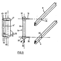
- FIGS 5 and 6 show in an exploded view the mounting or suspension of the individual wheels including the piston-cylinder units articulated on the longitudinal spars.
- the individual piston-cylinder unit 11 consists of a cylinder 31 which is provided with radially projecting thickenings 32 and 33 at its upper and lower ends is. At these thickened portions 32 and 33, stub axles 34 and 35 are fastened, which can preferably be hollow, in order to connect the upper and lower ends of the cylinder 31 to the compressed air container 25 by means of compressed air lines, not shown in detail.
- the two longitudinal spars 8 and 4 are provided with bearing bores 36 for receiving the stub axles 34 and 35, respectively.
- the piston rod 38 protruding from the cylinder 31 has a threaded section 39 at its lower end.
- a parallel guide element 40 is pushed onto the cylinder 31 between the radial thickenings 32 and 33.
- at least one of the two thickenings 32 or 33 is detachably attached to the cylinder 31.
- the parallel guide element 4o consists of a first pipe section 41 encompassing the cylinder 31, which is rigidly connected by means of a web 41 ′ and lower and upper trapezoidal stiffening plates 42 to a second pipe section 43 running parallel to the first pipe section 41.
- a steering bracket 53 is attached laterally.
- the second pipe section 43 serves for axially displaceable mounting of the parallel guide pipe 44 shown in FIG. 6, which is secured against rotation relative to the second pipe section 43.
- a cross bracket 45 is attached, to which a bearing cheek 46 is attached, which in turn runs parallel to the parallel guide tube 44.
- the crossbar 45 is provided with an upwardly open threaded bore 52 into which the threaded portion 39 of the piston rod 38 is screwed.
- both the parallel guide tube 44 and the bearing cheek 46 there are bearing bushes 47 and 48 for receiving the axle of a wheel 12.
- the cheek 46 is provided with a further bearing bore 49 for fastening the drive motor 3o, which is not described in detail Common gear elements shown are used to drive the wheel 12.
- a contact box 50 is preferably fastened in the area of the bearing bush 47, which serves with horizontally lying guide bores 51 for a contact bracket 28, which carries the bottom contact 29 already described above on its underside.
- the contact bracket 28 can be displaced in the horizontal direction against an elastic biasing force relative to the contact box 5o, in order to be able to actuate the side contacts arranged within the contact box 5o in the manner already described above.
- the piston rod 38 When compressed air is applied to the piston-cylinder unit 11, the piston rod 38 is either retracted or extended, as a result of which a correspondingly directed force is transmitted to the crossbar attached to the parallel guide tube 44.
- the parallel guide tube 44 is adjusted in the vertical direction within the second tube section 43, and thus also the wheel 12 mounted between the lower end of the parallel guide tube 44 and the bearing cheek 46.
- a pressure switch 54 is assigned to the second pipe section 43 and thus to the parallel guide pipe 44 (see FIGS. 2, 5 and 7).
- the pressure switch 54 fastened laterally in the region of a wall opening of the second pipe section 43 consists of a cylinder housing 55 in which a plunger 56 is slidably mounted.
- This plunger 56 is loaded on one side via a pressure plate 57 by a spring 58, which exerts a force on the plunger 56 in such a direction that a pressure ram 59 arranged on the other plunger cables is displaceable in an opening 61 of a cylinder cover 60 is stored, is extended so far from the cylinder that it is pressed through the above-mentioned wall opening of the second pipe section 43 into the locking and locking position against the parallel guide pipe 44.
- a compressed air line 62 which is also connected to the compressed air container 25, opens into the cylinder space of the cylinder 55 facing the cylinder cover 6o.
- compressed air supply to the plunger 56 of the associated pressure switch 54 is also required in order to move the pressure plunger 59 against the force of the spring 58 from the position inserted into the second pipe section 43 and locking the parallel guide pipe 44 can.
- the parallel guide tube 44 has reached an end position again, the compressed air supply to the plunger 56 is interrupted, so that the pressure ram 59 is then moved back into its position locking the parallel guide tube under the influence of the force of the spring 58.
- the pressure switch 54 thus fulfills the purpose of preventing uncontrolled vertical adjustments of the individual wheels in the event of faults in the compressed air system.
- a steering system or steering linkage engages in a manner not belonging to the invention individual steering straps 53 of the parallel guide elements 4o.
- the individual parallel guide element 40 is rotated with its first tube section 41 around the axis of the cylinder 11, which results in a corresponding pivoting movement of the second tube section 43.
- This pivoting movement is followed by the parallel guide tube 44 secured against rotation within the second tube section, which results in a corresponding change in the running or steering position of the individual wheel 12.
Abstract
Ein Rollstuhl für Behinderte mit einem auf einem Fahrgestell angebrachten Sitz (17), einem Batteriesatz für die Stromversorgung von den Rollstuhlrädern (12a bis 12h) zugeordneten Antriebsmotoren und einem Lenksystem zur Steuerung des Anschlages der Radgruppen ist zu dem Zweck, daß er selbstätig Treppen herauf- und herunterfahren kann, dadurch gekennzeichnet, daß das Fahrgestell zwei mit Abstand parallel übereinanderliegende Rahmen (1, 2) aufweist, die einen Druckluftbehälter mit zugeordnetem Kompressor tragen und an deren seitlichen Längsholmen (3, 4, 7, 8) für die Vertikalverstellung von acht, zu vier Radgruppen zusammengefaßten Rollstuhlrädern senkrechtstehende, doppelt wirkende Kolben-Zylinder-Einheiten (11a bis 11h) derart angelenkt sind, daß die Rahmen mit den Kolben-Zylinder-Einheiten in der seitlichen Projektion nach Art eines Parallelogrammgestänges verstellbar sind, daß der Sitz an dem oberen Rahmen (2) angelenkt ist, und daß dem Sitz zur Beibehaltung seiner waagerechten Stellung bei unterschiedlichen Relativstellungen der oberen und unteren Rahmen ein Stabilisierungssystem zugeordnet ist.A wheelchair for the disabled with a seat (17) mounted on a chassis, a battery set for the power supply of drive motors assigned to the wheelchair wheels (12a to 12h) and a steering system for controlling the stop of the wheel groups is for the purpose of automatically climbing stairs. and can drive down, characterized in that the chassis has two frames (1, 2) which are spaced parallel one above the other and which carry a compressed air tank with an associated compressor and on the side longitudinal bars (3, 4, 7, 8) for the vertical adjustment of eight, vertical, double-acting piston-cylinder units (11a to 11h) are articulated to form four wheel groups in such a way that the frames with the piston-cylinder units can be adjusted in the lateral projection in the manner of a parallelogram linkage so that the seat on the upper one Frame (2) is articulated, and that the seat to maintain its horizontal position a stabilization system is associated with different relative positions of the upper and lower frames.
Description
Die Erfindung betrifft einen Rollstuhl für Behinderte, wobei die Aufhängung eines Radpaares durch eine Kolben-Zylinder-Anordnung relativ zum Fahrgestell in vertikaler Richtung verstellt werden kann, mit einem auf einem Fahrgestell so angelenkten Sitz, daß der Sitz seine waagerechte Stellung bei unterschiedlichen Neigungen des Fahrgestells beibehalten kann und mit einer zentralen Steuereinheit zur pneumatischen Steuerung sowohl der Verstellung der Radlager als auch der Verstellung des Sitzes.The invention relates to a wheelchair for the disabled, the suspension of a pair of wheels can be adjusted in a vertical direction relative to the chassis by a piston-cylinder arrangement, with a seat articulated on a chassis so that the seat is in its horizontal position at different inclinations of the chassis can maintain and with a central control unit for pneumatic control both the adjustment of the wheel bearings and the adjustment of the seat.
Bei einem derartigen aus der DE-OS 27 41 323 bekannten Rollstuhl ist zusätzlich zu den Rädern ein in Fahrtrichtung des Fahrzeugs ausgerichtetes Laufband vorgesehen, welches im Bereich einer Treppe allein die Bodenoberfläche berührt. Bei einer derartigen Konstruktion besteht die Gefahr des Herunterrutschens.In such a wheelchair known from DE-OS 27 41 323, a treadmill oriented in the direction of travel of the vehicle is provided in addition to the wheels, which only touches the floor surface in the area of a staircase. With such a construction there is a risk of slipping down.
Der Erfindung liegt die Aufgabe zugrunde, einen Rollstuhl für Behinderte so zu gestalten, daß der in dem Rollstuhl sitzende Behinderte grundsätzlich ohne Mithilfe einer weiteren Person in der Lage ist, mit diesem Rollstuhl eine Treppe herauf- oder herabzufahren, wobei eine Hilfs- oder Begleitperson ohne Gefahr gegebenenfalls nur die Aufgabe haben soll, aus psychologischen Gründen eine Sicherungsfunktion gegen ein zu schnelles Überfahren der einzelnen Stufen auszuüben.The invention has for its object to design a wheelchair for the disabled so that the disabled in the wheelchair is basically able to go up or down stairs with this wheelchair without the help of another person, with an auxiliary or accompanying person without Perhaps only the task should be to exercise a safety function against psychologically crossing the individual steps too quickly for psychological reasons.
Zur Lösung dieser Aufgabe ist der erfindungsgemäße Rollstuhl dadurch gekennzeichnet, daß das Fahrgestell zwei mit Abstand parallel übereinanderliegende Rahmen aufweist, an deren seitlichen Längsholmen für die Vertikalverstellung von acht zu vier Radgruppen zusammengefaßten Rollstuhlrädern senkrechtstehende Kolben-Zylinder-Einheiten derart angelenkt sind, daß die Rahmen mit den Kolben-Zylinder-Einheiten in der seitlichen Projektion nach Art eines Parallelogrammgestänges verstellbar sind, wobei zwischen den Längsholmen Pneumatikzylinder zur Stabilisierung bzw. Fixierung der jeweiligen Relativstellungen zwischen den oberen und unteren Rahmen angelenkt sind und daß die Rollstuhlräder von durch einen Batteriesatz stromversorgte Motoren angetrieben werden.To achieve this object, the wheelchair according to the invention is characterized in that the chassis has two frames lying one above the other at a distance in parallel, on the lateral longitudinal spars for the vertical adjustment of eight wheelchair wheels combined into four wheel groups, vertical piston-cylinder units are articulated in such a way that the frame with the piston-cylinder units in the lateral projection are adjustable in the manner of a parallelogram linkage, with pneumatic cylinders being articulated between the longitudinal bars to stabilize or fixing the relative positions between the upper and lower frames, and that the wheelchair wheels are driven by motors powered by a battery pack .
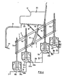
Bei einem derartigen Rollstuhl besteht die Möglichkeit, daß beispielsweise bei Herauffahren einer Treppe jeweils die Radgruppe, die gegen ein vertikales Hindernis in Form des Stoßtrittes einer Treppenstufe trifft, bis in den Bereich des Treppenauftrittes hochgehoben wird, so daß der Rollstuhl wieder weiter in Richtung der Treppe fahren kann. Bei jedem folgenden Anstoßen einer Radgruppe gegen einen Stoßtritt werden die entsprechenden Radgruppen angehoben, wobei es zu einer Schrägstellung der beiden Rahmen des Fahrgestelles kommt. Bezogen auf die einzelnen Radgruppen des Rollstuhles kommt es somit zu einem "raupenartigen" Hochbewegen entlang der Treppe. Dabei wird durch das dem Sitz zugeordnete Stabilisierungssystem gewährleistet, daß der Sitz seine waagerechte Stellung auch bei unterschiedlichen Relativstellungen zwischen oberen und unterem Rahmen beibehält.With such a wheelchair there is the possibility that depending on, for example, when climbing a staircase because the wheel group, which hits a vertical obstacle in the form of the impact step of a step, is lifted up into the area of the step, so that the wheelchair can continue to drive in the direction of the stairs. Each time a wheel group bumps against a kick, the corresponding wheel groups are raised, causing the two frames of the chassis to be inclined. In relation to the individual wheel groups of the wheelchair, there is a "caterpillar-like" movement along the stairs. The stabilization system assigned to the seat ensures that the seat maintains its horizontal position even with different relative positions between the upper and lower frame.
Dem Rollstuhl sind in weiterer Ausgestaltung der Erfindung Sicherheits-, Regel- und Steuereinrichtungen zugeordnet, wie sie in den Unteransprüchen beschrieben sind.In a further embodiment of the invention, the wheelchair is assigned safety, regulating and control devices as described in the subclaims.
Die Erfindung wird im folgenden anhand der Zeichnung näher erläutert.The invention is explained in more detail below with reference to the drawing.
Es zeigen:
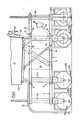
- Fig. 1 in schematischer Darstellung die Seitenansicht des auf einer ebenen Fläche stehenden Rollstuhles;
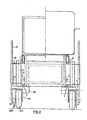
- Fig. 2 eine Rückansicht des Rollstuhles auf ebener Fläche;
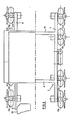
- Fig. 3 eine Draufsicht auf den Rollstuhl;
- Fig. 4 in schematischer Darstellung eine Seitenansicht des auf mehreren Treppenstufen einer Treppe stehenden Rollstuhles;
- Fig. 5 und 6 jeweils in auseinandergezogener Darstellung Einzelheiten der Radbefestigung und
- Fig. 7 eine Schnittansicht eines Druckwächters zur Sicherung der Räder gegen unbeabsichtigtes Verstellen in Vertikalrichtung.
- Figure 1 is a schematic representation of the side view of the wheelchair standing on a flat surface.
- Figure 2 is a rear view of the wheelchair on a flat surface.
- 3 is a top view of the wheelchair;
- 4 shows a schematic illustration of a side view of the wheelchair standing on several steps of a staircase;
- 5 and 6 each in an exploded view details of the wheel attachment and
- Fig. 7 is a sectional view of a pressure switch to secure the wheels against unintentional adjustment in the vertical direction.
Die Zeichnungen zeigen in verschiedenen Ansichten einen schematisch dargestellten Rollstuhl für Behinderte. Das Gestell dieses Rollstuhls besteht aus zwei übereinander gelagerten Rahmen 1 und 2, aus insbesondere Vierkantrohr. Der untere Rahmen 1 besteht aus zwei in Fahrtrichtung des Rollstuhles parallel laufenden Längsholmen 3 und 4 und zwei parallel liegenden Querholmen 5 und 6, die unter Bildung eines mittleren rechteckförmigen Rahmenteils mit Abstand von den Enden der Längsholme 3 und 4 an diesen befestigt sind. Der obere Rahmen 2 hat vorzugsweise die gleiche Form wie der untere Rahmen, d. h. der obere Rahmen besteht aus zwei parallel laufenden Längsholmen 7 und 8, die durch Querholme 9 und 10 miteinander verbunden sind. Die Form des oberen Rahmens 2 und damit auch die Form des unteren Rahmens ergeben sich insbesondere aus Figur 3.The drawings show in different views a schematically represented wheelchair for the disabled. The frame of this wheelchair consists of two
An den beiden Rahmen 1 und 2 sind über die Länge der Längsholme verteilt zu beiden Seiten der Rahmen 1 und 2 Zylinder 11a bis 11h von doppelt wirkenden Kolben-Zylinder-Einheiten angelenkt, derart, daß die Rahmen 1 und 2 zusammen mit den Zylindern in der seitlichen Projektion ein Parallellogrammgestänge bilden, dessen Beweglichkeit sich im wesentlichen aus den Figuren 1 und 4 (horizontale Ausgangslage einerseits und Schräglage andererseits) ergibt.On the two
Die Zylinder 11 a bis 11h bzw. die entsprechenden Kolben-Zylinder-Einheiten dienen zur Vertikalverstellung von luftbereiften Rädern 12a bis 12h, deren Lagerung weiter unten beschrieben wird.The
Zwischen den jeweils übereinanderliegenden Längsholmen 3 und 7 einerseits und 4 und 8 andererseits sind jeweils Pneumatikzylinder 13 bzw. 14 angelenkt, die dazu dienen, die jeweilige Relativstellung zwischen den oberen und unteren Rahmen zu stabilisieren bzw. zu fixieren.
Auf dem oberen Rahmen 2 ist mittels zwei auf den Längsholmen 7 bzw 8. befestigten Lagerböcken 15, 16 ein Sitz 17 schwenkbar gelagert. Zur Stabilisierung des Sitzes 17 dienen an beiden Längsseiten der Rahmen angeordnete Lenkerstangen 18 bzw. 19, die einerseits an den Längsholmen 3,4 des unteren Rahmens 1 und andererseits an der Unterseite des Sitzes 17 gelenkig befestigt sind. Die Länge der Lenkerstangen 18, 19 sowie die Lage der oberen und unteren Anlenkpunkte sind so aufeinander abgestimmt, daß unabhängig von der Stellung der beiden Rahmen 1 und 2 stets die gleiche Relativstellung des Sitzes relativ zu einer waagerrechten Bezugsebene gewährleistet ist, wie es sich aus den Figuren 1 und 4 ergibt. Für die Stabilisierung des Sitzes in seiner Horizontalstellung können auch andere Einrichtungen, vorzugsweise in Form von Pneumatikzylindern vorgesehen sein.A
Der Sitz 17 besteht im wesentlichen aus einem Vierkantrohr-Rahmen 20, an dem über ein Gestänge 21 Fußstützen 22 befestigt sind, sowie einer Sitzschale 23.The
An dem Sitz 17 sind ein nicht dargestellter Fahrt-Schalter und eine ebenfalls nicht dargestellte Lenkeinrichtung montiert.A travel switch (not shown) and a steering device (also not shown) are mounted on the
Grundlegende weitere Bestandteile des erfindungsgemäßen Rollstuhles sind ein an dem oberen Rahmen 2 drehbar befestigter Batteriesatz 24, ein auf dem unteren Rahmen 1 starr montierter Druckluft-Behälter 25 mit zugeordnetem Kompressor 26 und ein im einzelnen nicht dargestelltes Lenksystem zur Steurung des Einschlages der einzelnen Radgruppen.Basic further components of the wheelchair according to the invention are a
Der mittels des Kompressors 26 mit Druckluft versorgbare Druckluftbehälter 25 ist über nicht dargestellte Leitungen einerseits an die Zylinder 11a bis 11h sowie andererseits an die Pneumatikzylinder 13 und 14 angeschlossen. Eine an der Rückseite des Sitzes 17 befestigte Niveau-Regeleinrichtung 27 mit zugeordnetem Steuergerät dient zur Aufrechterhaltung der vorgegebenen Relativstellung des Sitzes 17 relativ zur waagerechten Bezugsebene und zur Steuerung der Beaufschlagung der einzelnen Zylindereinheiten 11a bis 11h und 13, 14 mit Druckluft.The
Den jeweils eine Radgruppe bildenen Rädern sind in waagerechter Richtung bewegliche, parallel geführte Kontaktbügel 28a bis 28h zugeordnet, die einerseits untere Bodenkontakte 29a bis 29h aufweisen und andererseits durch waagerechte Verschiebung nicht dargestellte Seitenkontakte betätigen können.The wheels, each forming a wheel group, are assigned horizontally
Jedem Rad 12a bis 12h ist ein elektrischer Antriebsmotor 30a bis 30h zugeordnet. Die Antriebsmotoren sind mittels nicht dargestellter Leitungen an den Batteriesatz 24 angeschlossen.An electric drive motor 30a to 30h is assigned to each
Die Funktionsfolge zum Treppauf-Fahren des erfindungsgemäßen Rollstuhls ist wie folgt: Die Antriebsmotoren 30a bis 30h treiben die Räder 12a bis 12h mit geringer Geschwindigkeit nach rückwärts an. Wenn die Kontaktbügel 29d, 29h des hinteren Radpaares 12d, 12h gegen den ersten Stoßtritt I stoßen und in waagerechter Richtung verstellt werden und dabei die Seitenkontakte betätigen, werden in die Niveau-Regeleinrichtung und das Steuergerät 27 integrierte Mikroprozessoren aller Radsätze angesteuert, um einerseits sämtliche Antriebsmotoren 30a bis 30h stillzusetzen und andererseits mit Ausnahme der Zylinder 11d, 11h sämtliche andere Zylinder 11a bis 11e derart mit Druckluft zu beaufschlagen, daß die zugeordneten Kolben und damit die Räder 12a bis 12g nach unten ausgefahren werden, wodurch der die Räder 12d und 12h umfassende Radsatz zusammen mit den Rahmen 1 und 2 nach oben angehoben wird, bis die zugeordneten Kontaktbügel 28d und 28h entlastet sind, d. h. nicht mehr gegen den Stoßtritt I anliegen.The sequence of functions for driving the wheelchair according to the invention up the stairs is as follows: the drive motors 30a to 30h drive the
Durch die dadurch erfolgende Entlastung der Kontaktbügel 28d, 28h werden innerhalb des Gerätes 27 erneute Steuerbefehle in der Weise ausgelöst, daß sämtliche Antriebsmotoren 30a bis 30h wieder im Rückwärtsgang angetrieben werden.Due to the resulting relief of the
Bei jedem folgenden Anstoßen eines Kontaktbügelpaares gegen einen der Stoßtritte I, II, III oder VI einer Treppe wiederholen sich gleiche oder vergleichbare Vorgänge in der Weise, daß einerseits die Antriebsmotoren 30a bis 30h stillgesetzt werden und andererseits bestimmte Radsätze ein-oder ausgefahren werden, derart, daß jeweils der mit seinen Kontaktbügeln gegen einen der Stoßtritte anstoßende Radsatz relativ zu den anderen Radsätzen verstellt wird. Dabei ergibt sich gleichzeitig eine Schrägstellung der beiden Rahmen 1 und 2, wobei von dem Steuergerät 27 Steuerbefehle einerseits an die Zylinder 12a bis 12h und andererseits an die Pneumatikzylinder 13 und 14 gegeben werden, um in Abhängigkeit von dem Ein- oder Ausfahrzustand der einzelnen Radsätze die entsprechende Schrägstellung der beiden Rahmen 1 und 2 zu steuern.Each time a pair of contact brackets bumps against one of the kick steps I, II, III or VI of a staircase, the same or comparable processes are repeated in such a way that on the one hand the drive motors 30a to 30h are stopped and on the other hand certain wheel sets are retracted or extended, that in each case the wheel set abutting one of the kick steps with its contact brackets is adjusted relative to the other wheel sets. This results in an inclined position of the two
Während dieser Aufwärtsbewegung des Rollstuhles sind die einzelnen Räder gegen Vorwärtslauf blockiert.During this upward movement of the wheelchair, the individual wheels are blocked against forward running.
Für das "Herunterfahren" einer Treppe ergibt sich folgende Funktionsfolge: Die Antriebsmotoren 30a bis 30h werden mit geringer Geschwindigkeit im Vorwärtsgang angetrieben.The following sequence of functions results for the “descending” of a staircase: the drive motors 30a to 30h are driven at low speed in the forward gear.
Wenn die vorlaufenden Räder 12a, 12e den obersten Treppenauftritt VIa verlassen und unmittelbar danach die zugeordneten Bodenkontakte 29a, 29e auf diesen Treppenauftritt VIa auftreffen und dadurch belastet werden, werden die Pneumatikzylinder 11a, 11e gesperrt. Beim Weiterfahren werden die Bodenkontakte 29a, 29e wieder entlastet, was zur Folge hat, daß alle Antriebsmotoren angehalten werden. Gleichzeitig werden die Zylindereinheiten 11a, 11b entsperrt, und fahren zum darunterliegenden Treppenauftritt IIIa. Danach werden die Antriebsmotoren 3oa bis 3oh nach einer durch Mikroprozessoren gesteuerten Zeitverzögerung wieder in Gang gesetzt, so daß die Räder 12a bis 12h im Vorwärtslauf angetrieben werden. Bei jeder nachfolgenden Entlastung und Wiederbelastung von Bodenkontakten werden entsprechende Steuerbefehle ausgelöst mit der Maßgabe, daß stets gewährleistet ist, daß zmindest drei Radsätze in Bodenhaftung verbleiben und andererseits die Schrägstellung der Rahmen 1 und 2 in Abhängigkeit davon gesteuert wird, welche Höhenstellung die einzelnen Radsätze in Abhängigkeit von der Abwärtsbewegung des Rollstuhles jeweils einnehmen.If the leading
Um für den Fall eines plötzlichen Druckabfalles im Druckluftsystems Vorsorge zu treffen, ist ein Elockiersystem vorgesehen, um sämtliche Zylinder 11a bis 11h sowie die Pneumatikzylinder 13 und 14 in der jeweiligen Lage zu sperren.In order to take precautions in the event of a sudden pressure drop in the compressed air system, an locking system is provided in order to lock all
Die Figuren 5 und 6 zeigen in auseinandergezogener Darstellung die Lagerung bzw. Aufhängung der einzelnen Räder einschließlich der an den Längsholmen gelenkig gelagerten Kolben-Zylinder-Einheiten. Die einzelne Kolben-Zylinder-Einheit 11 besteht aus einem Zylinder 31, der an seinen oberen und unteren Enden mit radial vorstehenden Verdickungen 32 bzw. 33 versehen ist. An diesen Verdickungen 32 und 33 sind Achsstummel 34 bzw. 35 befestigt, die vorzugsweise hohl gestaltet sein können, um mittels im einzelnen nicht dargestellter Druckluftleitungen die oberen und unteren Enden des Zylinders 31 an den Druckluftbehälter 25 anzuschließen. Die beiden Längsholme 8 und 4 sind mit Lagerbohrungen 36 zur Aufnahme der Achsstummel 34 bzw. 35 versehen. Die aus dem Zylinder 31 ragende Kolbenstange 38 hat an ihrem unteren Ende einen Gewindeabschnitt 39.Figures 5 and 6 show in an exploded view the mounting or suspension of the individual wheels including the piston-cylinder units articulated on the longitudinal spars. The individual piston-
Auf den Zylinder 31 wird zwischen den radialen Verdickungen 32 und 33 ein Parallelführungselement 4o aufgeschoben. Zu diesem Zweck ist zumindest einer der beiden Verdickungen 32 oder 33 lösbar an dem Zylinder 31 befestigt. Das Parallelführungselement 4o besteht aus einem ersten, den Zylinder 31 umgreifenden Rohrabschnitt 41, der mittels eines Steges 41' und untere und oberen trapezförmigen Versteifungsplatten 42 starr mit einem zum ersten Rohrabschnitt 41 parallelverlaufenden zweiten Rohrabschnitt 43 verbunden ist.A
An dem ersten Rohrabschnitt 41 des Parallelführungselementes 4o ist seitlich eine Lenklasche 53 befestigt.On the
Der zweite Rohrabschnitt 43 dient zur in Achsrichtung verschiebbaren Lagerung des in Fig. 6 dargestellten Parallelführungsrohres 44, das gegen eine Drehung relativ zum zweiten Rohrabschnitt 43 gesichert ist. Im Bereich des unteren Abschnittes des Parallelführungsrohres 44 ist ein Querbügel 45 befestigt, an dem eine Lagerwange 46 befestigt ist, die wiederum parallel zum Parallelführungsrohr 44 verläuft.The second pipe section 43 serves for axially displaceable mounting of the
Der Querbügel 45 ist mit einer nach oben hin offenen Gewindebohrung 52 versehen, in die der Gewindeabschnitt 39 der Kolbenstange 38 eingeschraubt wird.The
An den unteren Enden sowohl des Parallelführungsrohres 44 als auch der Lagerwange 46 befinden sich Lagerbüchsen 47 bzw. 48 zur Aufnahme der Achse eines Rades 12. Die Wange 46 ist mit einer weiteren Lagerbohrung 49 für die Befestigung des Antriebsmotores 3o versehen, der über im einzelnen nicht dargestellte übliche Getriebeelemente zum Antrieb des Rades 12 dient.At the lower ends of both the
An dem unteren Ende des Parallelführungsrohres 44 ist vorzugsweise im Bereich der Lagerbüchse 47 ein Kontaktkasten 5o befestigt, der mit waagerecht liegenden Führungsbohrungen 51 für einen Kontaktbügel 28 dient, der an seiner Unterseite den bereits oben beschriebenen Bodenkontakt 29 trägt. Der Kontaktbügel 28 ist gegen eine elastische Vorspannkraft in waagerechter Richtung relativ zum Kontaktkasten 5o verschiebbar, um in der oben bereits beschriebenen Weise die innerhalb des Kontaktkastens 5o angeordneten Seitenkontakte betätigen zu können.At the lower end of the
Bei Beaufschlagung der Kolben-Zylinder-Einheit 11 mit Druckluft wird die Kolbenstange 38 entweder ein- oder ausgefahren, wodurch eine entsprechend gerichtete Kraft auf den an dem Parallelführungsrohr 44 befestigten Querbügel übertragen wird. Dadurch wird das Parallelführungsrohr 44 innerhalb des zeiten Rohrabschnittes 43 in vertikaler Richtung verstellt und damit auch das zwischen dem unteren Ende des Parallelführungsrohres 44 und der Lagerwange 46 gelagerte Rad 12.When compressed air is applied to the piston-
Aus Sicherheitsgründen ist dem zweiten Rohrabschnitt 43 und damit dem Parallelführungsrohr 44 ein Druckwächter 54 zugeordnet (siehe Fig. 2, 5 und 7).For safety reasons, a
Der seitlich im Bereich einer Wandöffnung des zweiten Rohrabschnittes 43 befestigte Druckwächter 54 besteht aus einem Zylindergehäuse 55, in dem ein Plunger 56 verschiebbar gelagert ist. Dieser Plunger 56 ist auf der einen Seite über eine Druckplatte 57 von einer Feder 58 belastet, die auf den Plunger 56 eine Kraft in einer solchen Richtung ausübt, daß ein an der anderen Plungerseile angeordneter Druckstempel 59, der in einer öffnung 61 eines Zylinderdeckels 6o verschiebbar gelagert ist, aus dem Zylinder so weit ausgefahren wird, daß er durch die oben genannte Wandöffnung des zweiten Rohrabschnittes 43 hindurch in Anlage- und Verriegelungsstellung gegen das Parallelführungsrohr 44 gedrückt wird. In den dem Zylinderdeckel 6o zugewandten Zylinderraum des Zylinders 55 mündet eine Druckluftleitung 62, die ebenfalls an den Druckluftbehälter 25 angeschlossen ist. Zur Verstellung eines Rades ist neben der Druckluftbeaufschlagung des jeweiligen Zylinders 31 auch eine Druckluftbeaufschlagung des Plungers 56 des zugeordneten Druckwächters 54 erforderlich, um den Druckstempel 59 entgegen der Kraft der Feder 58 aus der in den zweiten Rohrabschnitt 43 eingefahrenen und das Parallelführungsrohr 44 verriegelnden Stellung bewegen zu können. Sobald das Parallelführungsrohr 44 wieder eine Endstellung erreicht hat, wird die Druckluftbeaufschlagung des Plungers 56 unterbrochen, so daß dann der Druckstempel 59 unter dem Einfluß der Kraft der Feder 58 wieder in seine das Parallelführungsrohr verriegelnde Stellung ausgefahren wird.The
Der Druckwächter 54 erfüllt somit den Zweck, bei Störungen im Druckluftsystem unkontrollierte Vertikalverstellungen der einzelnen Räder zu verhindern.The
Ein nicht dargestelltes Lenksystem oder Lenkgestänge greift in nicht zur Erfindung gehörender Weise an den einzelnen Lenklaschen 53 der Parallelführungselemente 4o an. Zur Einstellung der Spur der einzelnen Räder wird das einzelne Parallelführungselement 4o mit seinem ersten Rohrabschnitt 41 um die Achse des Zylinders 11 gedreht, was eine entsprechende Schwenkbewegung des zweiten Rohrabschnittes 43 zur Folge hat. Dieser Schwenkbewegung folgt das innerhalb des zweiten Rohrabschnittes gegen Drehung gesicherte Parallelführungsrohr 44, was eine ensprechende Veränderung der Lauf- bzw. Lenkstellung des einzelnen Rades 12 zur Folge hat.A steering system or steering linkage, not shown, engages in a manner not belonging to the invention individual steering straps 53 of the parallel guide elements 4o. To set the track of the individual wheels, the individual
Claims (12)
Applications Claiming Priority (2)
| Application Number | Priority Date | Filing Date | Title |
|---|---|---|---|
| DE3225354 | 1982-07-07 | ||
| DE3225354A DE3225354C2 (en) | 1982-07-07 | 1982-07-07 | Wheelchair for the disabled |
Publications (1)
| Publication Number | Publication Date |
|---|---|
| EP0100449A1 true EP0100449A1 (en) | 1984-02-15 |
Family
ID=6167830
Family Applications (1)
| Application Number | Title | Priority Date | Filing Date |
|---|---|---|---|
| EP83106471A Ceased EP0100449A1 (en) | 1982-07-07 | 1983-07-02 | Wheel-chair for invalids |
Country Status (5)
| Country | Link |
|---|---|
| US (1) | US4569409A (en) |
| EP (1) | EP0100449A1 (en) |
| JP (1) | JPS5964045A (en) |
| DE (1) | DE3225354C2 (en) |
| ES (1) | ES8403717A1 (en) |
Cited By (6)
| Publication number | Priority date | Publication date | Assignee | Title |
|---|---|---|---|---|
| GB2201926A (en) * | 1987-03-04 | 1988-09-14 | Monticolombi C G R | Improvements in or relating to a stair-climbing device |
| EP0156807B1 (en) * | 1983-09-09 | 1991-02-06 | HESTER, Robert | Vehicle and method of operating same |
| GB2325903A (en) * | 1997-06-06 | 1998-12-09 | Robert George Hester | Kerb mounting wheeled conveyance |
| WO2001053137A1 (en) * | 2000-01-17 | 2001-07-26 | Elsteel Danmark A/S | Transport arrangement and method of controlling a transport arrangement |
| CN109363844A (en) * | 2018-12-13 | 2019-02-22 | 西安交通大学 | A kind of obstacle crosses over control device and control method |
| EP3679912A2 (en) | 2019-01-09 | 2020-07-15 | Ammann, Gerda | Wheelchair for overcoming obstacles |
Families Citing this family (37)
| Publication number | Priority date | Publication date | Assignee | Title |
|---|---|---|---|---|
| JPS62117558A (en) * | 1985-11-18 | 1987-05-29 | 東邦機工株式会社 | Wheelchair freely rising and falling along upstairs |
| IL98207A (en) * | 1991-05-22 | 1994-08-26 | Israel Aircraft Ind Ltd | Wheelchair with apparatus for assisting travel on a surface not suitable for wheeled travel |
| US5507358A (en) * | 1993-06-04 | 1996-04-16 | Kabushiki Kaisha Daikin Seisakusho | Stair climbing vehicle |
| US5562172A (en) * | 1994-01-06 | 1996-10-08 | Mick; Jeffrey | Wheeled vehicle arrangement for distributing agricultural materials in fields having undulations such as soft walled levees and the like |
| US6003624A (en) * | 1995-06-06 | 1999-12-21 | University Of Washington | Stabilizing wheeled passenger carrier capable of traversing stairs |
| JPH09309469A (en) * | 1996-05-23 | 1997-12-02 | Exedy Corp | Staircase ascending and descending vehicle |
| US6276704B1 (en) * | 1997-09-23 | 2001-08-21 | Charles J. Suiter | Adjustable wheelchair having a tilting and reclining seat |
| GB2340090B (en) | 1998-07-31 | 2001-06-13 | Ferno Washington | Chairs |
| DE19955199C1 (en) * | 1999-11-16 | 2001-06-13 | Karlsruhe Forschzent | Stair-mounting electric wheel chair; has wheels arranged on wheel arms and mounted in body with hinged and rigid climbing arms to form wheel-climbing modules, where climbing arms are linearly guided |
| US6695084B2 (en) * | 2001-02-22 | 2004-02-24 | Peter J. Wilk | Personal hovercraft with stairway climbing |
| CN1582873B (en) * | 2003-08-22 | 2010-04-28 | 贾荣显 | Pneumatic wheeled chair for going on stairs |
| US7246671B2 (en) * | 2005-01-10 | 2007-07-24 | Michael Goren | Stair-climbing human transporter |
| WO2007079346A2 (en) * | 2005-12-30 | 2007-07-12 | Olsen Christopher J | Articulated wheel assemblies and vehicles therewith |
| TW200844406A (en) * | 2007-05-02 | 2008-11-16 | Univ Nat Chiao Tung | Sensing apparatus |
| TW200843992A (en) * | 2007-05-02 | 2008-11-16 | Univ Nat Chiao Tung | Carrier with barrier-overpassing |
| DE102009052215A1 (en) | 2009-11-06 | 2011-05-12 | Medvetskiy, Oleksandr | Hand two-wheeler trolley has device for overcoming close and deep obstacles, whose underbody is implemented in form of hard framework and has axle with two wheels fixed at end of axle |
| DE202010001115U1 (en) | 2010-01-20 | 2010-06-17 | Medvetskiy, Oleksandr | The manual two-wheeled cart or suitcase with the device for overcoming narrow and deep obstacles |
| US8418787B2 (en) | 2011-01-10 | 2013-04-16 | King Fahd University Of Petroleum And Minerals | Stair climbing apparatus |
| CN102730097A (en) * | 2011-04-14 | 2012-10-17 | 牛晓蓉 | Multipurpose stair step-climbing motor vehicle |
| CN102319153B (en) * | 2011-06-23 | 2014-03-26 | 耿冬 | Manual stair climbing vehicle |
| ES2417979B1 (en) * | 2011-09-24 | 2014-10-30 | Bayron Sicilia Acosta | Mechanism with Arm-Ramp for Climbing and Lowering Stairs |
| US8764027B1 (en) | 2013-01-28 | 2014-07-01 | Michael Della Polla | Slab dolly |
| CN104207899B (en) * | 2014-03-27 | 2016-08-24 | 刘继伦 | Stair climbing wheelchair |
| CN104546327A (en) * | 2015-01-20 | 2015-04-29 | 王宝金 | Folding type transversely-moving electric stair climbing wheelchair |
| US9937968B2 (en) | 2015-07-13 | 2018-04-10 | Michael Goren | Stackable vehicle |
| US10202141B2 (en) | 2015-07-13 | 2019-02-12 | Hurdler Motors | Vehicle, vehicle drive assembly and vehicle steering assembly |
| US10912688B2 (en) | 2015-09-25 | 2021-02-09 | The United States Government As Represented By The Department Of Veterans Affairs | Mobility enhancement wheelchair |
| DE202015006899U1 (en) | 2015-10-01 | 2016-02-12 | Andreas Wulff | walker |
| DE102015012755A1 (en) | 2015-10-01 | 2017-04-06 | Andreas Wulff | walker |
| ES2873201T3 (en) * | 2015-11-23 | 2021-11-03 | Quantum Robotic Systems Inc | Device for crossing stairs |
| JP6055981B1 (en) * | 2016-01-29 | 2017-01-11 | 株式会社コスモテック | Stair lift electric wheelchair |
| CN106742880B (en) * | 2016-12-28 | 2019-07-19 | 中铁工程装备集团有限公司 | A kind of swing type tank body mobile device |
| CN108502045B (en) * | 2018-04-04 | 2020-06-19 | 罗冯涛 | Traveling mechanism |
| CN109512593B (en) * | 2018-11-19 | 2020-05-08 | 潘柏翰 | Self-balancing wheelchair suitable for climbing stairs |
| ES2950779R1 (en) * | 2020-10-18 | 2024-02-28 | Liberdade De Movimentos Unipessoal Lda | Wheelchair/stretcher |
| CN113116648B (en) * | 2021-04-13 | 2023-04-25 | 聊城大学 | Shock-absorbing stair climbing obstacle surmounting device and wheelchair |
| CN113175165A (en) * | 2021-05-07 | 2021-07-27 | 安徽锦允新材料科技有限公司 | Intelligent home stair structure assisting wheelchair in climbing |
Citations (9)
| Publication number | Priority date | Publication date | Assignee | Title |
|---|---|---|---|---|
| US3231036A (en) * | 1961-05-15 | 1966-01-25 | Appenrodt Richard | Stair climbing invalid carriages |
| US3269478A (en) * | 1965-12-06 | 1966-08-30 | Donald E Joslyn | Stair climbing wheel chair |
| US3438641A (en) * | 1966-03-31 | 1969-04-15 | Bartholomew M Bradley | Stair climbing wheelchair |
| US3554309A (en) * | 1968-10-10 | 1971-01-12 | Lucas L Abercrombie | Power-operated load transporting device |
| US3592282A (en) * | 1969-09-12 | 1971-07-13 | Robert L Soileau | Stair-traversing wheelchair apparatus |
| DE2524717A1 (en) * | 1975-06-04 | 1976-12-16 | Walter Schmidt | Load carrying stair climbing trolley - with front and rear axles on pivotted yoke with hydraulic rams |
| US4200161A (en) * | 1976-02-10 | 1980-04-29 | Penington George W Jr | Stairway climbing device |
| US4222449A (en) * | 1978-06-08 | 1980-09-16 | Feliz Jack M | Step-climbing wheel chair |
| GB2043554A (en) * | 1979-02-02 | 1980-10-08 | Biddle Eng Co Ltd | Motorised wheelchairs |
Family Cites Families (2)
| Publication number | Priority date | Publication date | Assignee | Title |
|---|---|---|---|---|
| FR2232475A1 (en) * | 1973-06-06 | 1975-01-03 | Tyszkiewicz Stefan | Baggage trolley or invalid chair - telescopic legs and lever system maintain platform level on gradient or steps |
| DE2741323A1 (en) * | 1977-03-10 | 1978-09-14 | Werner Klaus Konzack | Hand propelled vehicle e.g. pram - has wheels mounted on pivoted arms allowing tracks to be used on rough ground or steps |
-
1982
- 1982-07-07 DE DE3225354A patent/DE3225354C2/en not_active Expired
-
1983
- 1983-07-02 EP EP83106471A patent/EP0100449A1/en not_active Ceased
- 1983-07-05 US US06/511,162 patent/US4569409A/en not_active Expired - Fee Related
- 1983-07-07 JP JP58122494A patent/JPS5964045A/en active Pending
- 1983-07-07 ES ES523946A patent/ES8403717A1/en not_active Expired
Patent Citations (9)
| Publication number | Priority date | Publication date | Assignee | Title |
|---|---|---|---|---|
| US3231036A (en) * | 1961-05-15 | 1966-01-25 | Appenrodt Richard | Stair climbing invalid carriages |
| US3269478A (en) * | 1965-12-06 | 1966-08-30 | Donald E Joslyn | Stair climbing wheel chair |
| US3438641A (en) * | 1966-03-31 | 1969-04-15 | Bartholomew M Bradley | Stair climbing wheelchair |
| US3554309A (en) * | 1968-10-10 | 1971-01-12 | Lucas L Abercrombie | Power-operated load transporting device |
| US3592282A (en) * | 1969-09-12 | 1971-07-13 | Robert L Soileau | Stair-traversing wheelchair apparatus |
| DE2524717A1 (en) * | 1975-06-04 | 1976-12-16 | Walter Schmidt | Load carrying stair climbing trolley - with front and rear axles on pivotted yoke with hydraulic rams |
| US4200161A (en) * | 1976-02-10 | 1980-04-29 | Penington George W Jr | Stairway climbing device |
| US4222449A (en) * | 1978-06-08 | 1980-09-16 | Feliz Jack M | Step-climbing wheel chair |
| GB2043554A (en) * | 1979-02-02 | 1980-10-08 | Biddle Eng Co Ltd | Motorised wheelchairs |
Cited By (6)
| Publication number | Priority date | Publication date | Assignee | Title |
|---|---|---|---|---|
| EP0156807B1 (en) * | 1983-09-09 | 1991-02-06 | HESTER, Robert | Vehicle and method of operating same |
| GB2201926A (en) * | 1987-03-04 | 1988-09-14 | Monticolombi C G R | Improvements in or relating to a stair-climbing device |
| GB2325903A (en) * | 1997-06-06 | 1998-12-09 | Robert George Hester | Kerb mounting wheeled conveyance |
| WO2001053137A1 (en) * | 2000-01-17 | 2001-07-26 | Elsteel Danmark A/S | Transport arrangement and method of controlling a transport arrangement |
| CN109363844A (en) * | 2018-12-13 | 2019-02-22 | 西安交通大学 | A kind of obstacle crosses over control device and control method |
| EP3679912A2 (en) | 2019-01-09 | 2020-07-15 | Ammann, Gerda | Wheelchair for overcoming obstacles |
Also Published As
| Publication number | Publication date |
|---|---|
| ES523946A0 (en) | 1984-04-16 |
| JPS5964045A (en) | 1984-04-11 |
| US4569409A (en) | 1986-02-11 |
| ES8403717A1 (en) | 1984-04-16 |
| DE3225354A1 (en) | 1984-01-19 |
| DE3225354C2 (en) | 1984-04-26 |
Similar Documents
| Publication | Publication Date | Title |
|---|---|---|
| DE3225354C2 (en) | Wheelchair for the disabled | |
| DE2807519C2 (en) | Driving and walking gear | |
| EP0416539B1 (en) | Entrance device for motor vehicles, in particular for buses | |
| DE2807517A1 (en) | WHEEL SUSPENSION | |
| EP0466065B1 (en) | Load handling vehicle | |
| DE2527100A1 (en) | OFF-ROAD VEHICLE | |
| DE2317824A1 (en) | SEAT FOR TUGS AND OTHER VEHICLES | |
| EP3473506B1 (en) | Connecting device for a vehicle | |
| DE3316014A1 (en) | Vehicle for travelling over steps | |
| DE2521623B2 (en) | Floor support for mobile construction machinery | |
| DE2636656A1 (en) | Road or track adaptable urban transport system - has retractable system guide rollers on ends of arms attached to non-resilient parts of vehicle axles | |
| WO2005099646A1 (en) | Stair climber for autonomous climbing, adaptable to manual wheelchairs | |
| EP0678443B1 (en) | Running gear, especially for mobile working machines and vehicles | |
| EP0429033B1 (en) | Aircraft passenger stairs | |
| EP0200045A2 (en) | Parking of a motorcycle | |
| DE3123145A1 (en) | Passenger transport vehicle | |
| EP0617945A2 (en) | Bed, especially a bed for patients and/or bed for nursing | |
| WO2005097033A1 (en) | Wheelchair comprising a central wheel drive unit, particularly elevated wheelchair | |
| DE60218731T2 (en) | wheelchair | |
| DE3422255A1 (en) | Chassis for a wheelchair | |
| CH634984A5 (en) | Wheelchair | |
| DE2722605A1 (en) | SELF-PROPELLED SUPPORT DEVICE | |
| DE602004004389T2 (en) | Vehicle for the disabled | |
| DE2419553A1 (en) | Wheelchair climbing stairs by endless tracks fore and aft with reversible electric motors driving left and right tracks separately | |
| EP0816279A1 (en) | Car jack for manoeuvring |
Legal Events
| Date | Code | Title | Description |
|---|---|---|---|
| PUAI | Public reference made under article 153(3) epc to a published international application that has entered the european phase |
Free format text: ORIGINAL CODE: 0009012 |
|
| AK | Designated contracting states |
Designated state(s): AT BE CH FR GB IT LI LU NL SE |
|
| 17P | Request for examination filed |
Effective date: 19840711 |
|
| STAA | Information on the status of an ep patent application or granted ep patent |
Free format text: STATUS: THE APPLICATION HAS BEEN REFUSED |
|
| 18R | Application refused |
Effective date: 19860316 |