WO2016186032A1 - Endoscopic treatment instrument - Google Patents
Endoscopic treatment instrument Download PDFInfo
- Publication number
- WO2016186032A1 WO2016186032A1 PCT/JP2016/064315 JP2016064315W WO2016186032A1 WO 2016186032 A1 WO2016186032 A1 WO 2016186032A1 JP 2016064315 W JP2016064315 W JP 2016064315W WO 2016186032 A1 WO2016186032 A1 WO 2016186032A1
- Authority
- WO
- WIPO (PCT)
- Prior art keywords
- basket
- operation wire
- support member
- sheath
- central axis
- Prior art date
Links
Images


Classifications
-
- A—HUMAN NECESSITIES
- A61—MEDICAL OR VETERINARY SCIENCE; HYGIENE
- A61B—DIAGNOSIS; SURGERY; IDENTIFICATION
- A61B17/00—Surgical instruments, devices or methods, e.g. tourniquets
- A61B17/50—Instruments, other than pincettes or toothpicks, for removing foreign bodies from the human body
-
- A—HUMAN NECESSITIES
- A61—MEDICAL OR VETERINARY SCIENCE; HYGIENE
- A61B—DIAGNOSIS; SURGERY; IDENTIFICATION
- A61B17/00—Surgical instruments, devices or methods, e.g. tourniquets
- A61B17/00234—Surgical instruments, devices or methods, e.g. tourniquets for minimally invasive surgery
-
- A—HUMAN NECESSITIES
- A61—MEDICAL OR VETERINARY SCIENCE; HYGIENE
- A61B—DIAGNOSIS; SURGERY; IDENTIFICATION
- A61B17/00—Surgical instruments, devices or methods, e.g. tourniquets
- A61B17/22—Implements for squeezing-off ulcers or the like on the inside of inner organs of the body; Implements for scraping-out cavities of body organs, e.g. bones; Calculus removers; Calculus smashing apparatus; Apparatus for removing obstructions in blood vessels, not otherwise provided for
- A61B17/221—Gripping devices in the form of loops or baskets for gripping calculi or similar types of obstructions
-
- A—HUMAN NECESSITIES
- A61—MEDICAL OR VETERINARY SCIENCE; HYGIENE
- A61B—DIAGNOSIS; SURGERY; IDENTIFICATION
- A61B17/00—Surgical instruments, devices or methods, e.g. tourniquets
- A61B17/00234—Surgical instruments, devices or methods, e.g. tourniquets for minimally invasive surgery
- A61B2017/00292—Surgical instruments, devices or methods, e.g. tourniquets for minimally invasive surgery mounted on or guided by flexible, e.g. catheter-like, means
- A61B2017/003—Steerable
- A61B2017/00305—Constructional details of the flexible means
- A61B2017/00314—Separate linked members
-
- A—HUMAN NECESSITIES
- A61—MEDICAL OR VETERINARY SCIENCE; HYGIENE
- A61B—DIAGNOSIS; SURGERY; IDENTIFICATION
- A61B17/00—Surgical instruments, devices or methods, e.g. tourniquets
- A61B17/00234—Surgical instruments, devices or methods, e.g. tourniquets for minimally invasive surgery
- A61B2017/00292—Surgical instruments, devices or methods, e.g. tourniquets for minimally invasive surgery mounted on or guided by flexible, e.g. catheter-like, means
- A61B2017/003—Steerable
- A61B2017/00318—Steering mechanisms
- A61B2017/00323—Cables or rods
-
- A—HUMAN NECESSITIES
- A61—MEDICAL OR VETERINARY SCIENCE; HYGIENE
- A61B—DIAGNOSIS; SURGERY; IDENTIFICATION
- A61B17/00—Surgical instruments, devices or methods, e.g. tourniquets
- A61B2017/00743—Type of operation; Specification of treatment sites
- A61B2017/00818—Treatment of the gastro-intestinal system
-
- A—HUMAN NECESSITIES
- A61—MEDICAL OR VETERINARY SCIENCE; HYGIENE
- A61B—DIAGNOSIS; SURGERY; IDENTIFICATION
- A61B17/00—Surgical instruments, devices or methods, e.g. tourniquets
- A61B17/22—Implements for squeezing-off ulcers or the like on the inside of inner organs of the body; Implements for scraping-out cavities of body organs, e.g. bones; Calculus removers; Calculus smashing apparatus; Apparatus for removing obstructions in blood vessels, not otherwise provided for
- A61B17/221—Gripping devices in the form of loops or baskets for gripping calculi or similar types of obstructions
- A61B2017/2212—Gripping devices in the form of loops or baskets for gripping calculi or similar types of obstructions having a closed distal end, e.g. a loop
Definitions
- the present invention relates to an endoscopic treatment tool that collects foreign substances in the body.
- Patent Document 1 discloses an endoscopic treatment tool that includes a basket portion made of a plurality of spiral elastic wires, and stores and collects stones in the basket portion.
- a support member is provided on the basket portion in order to prevent the entire basket portion from bending and falling down.
- the support member has a tip fixed to the tip of the basket portion and is disposed in the basket portion, and a proximal end is disposed along the proximal portion of the basket portion and is inserted into the flexible sheath.
- the basket portion When collecting a large calculus using an endoscope treatment tool having such a basket portion, for example, the basket portion is caught in the bile duct due to the relationship between the size of the basket portion containing the calculus and the size of the lumen. In some cases, the basket portion may become stuck in the bile duct.
- a treatment for pulverizing the calculus in the basket portion is performed using the calculus crushing device disclosed in Patent Document 2.
- the calculus crushing device disclosed in Patent Document 2 when incarceration occurs, the treatment tool in a state where the calculus is accommodated in the basket portion is inserted after cutting the proximal end portion of the operation wire of the treatment tool exposed outside the body.
- the flexible sheath and endoscope that have been removed are removed from the body.
- the coil sheath is inserted into the body while reaching the proximal end of the basket portion while covering the cutting portion of the operation wire of the treatment tool with the coil sheath of the calculus crusher.
- the wire in the basket portion strongly tightens the stone and crushes the stone.
- the basket can be removed from the bile duct.
- the present invention provides an endoscopic treatment tool that can be easily connected to a calculus crusher and can be suitably urgently crushed even when incarceration occurs in a lumen such as a bile duct.
- the purpose is to provide.
- An endoscope treatment tool includes an operation wire that is inserted into a flexible sheath so as to be able to advance and retreat, and an elastic member that is positioned on the distal end side of the operation wire and has a helical shape in a natural state.
- a basket portion formed by bundling a plurality of basket wires, a tip for bundling and fixing the tips of the basket wires at the tip of the basket portion, and base ends of the basket wires being bundled
- a bundling portion to be fixed and a support member that is disposed so as to pass through the basket portion along the central axis of the basket portion, and a distal end portion of which is fixed to the distal end tip, and a base end portion of the support member Is connected to the operation wire so as to be slidable in the central axis direction with respect to the operation wire.
- the connecting portion and the binding portion of the tip of the plurality of basket wires and the tip of the tip are positioned on the central axis.
- the support member may be disposed at a position offset radially outward with respect to the central axis.
- the base end portion of the support member and the operation wire are connected.
- the connecting member further includes a sliding portion that is slidable with respect to the operation wire, and a holding portion that holds the base end portion of the support member at a position offset with respect to the central axis. You may have.
- connection member is formed of a pipe-shaped member, and the through hole through which the operation wire is inserted and the support member are inserted.
- the insertion hole to be formed may be formed side by side in the central axis direction.
- connection member is provided at a position extending from a base end of the support member, and the operation wire is inserted therethrough. You may have a loop part.
- the endoscopic treatment tool of the present invention can be easily connected to a calculus pulverizer even when incarceration occurs in a lumen, and emergency pulverization can be suitably performed.
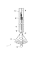
- FIG. 1 is a cross-sectional view of the treatment instrument 1.
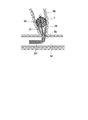
- FIG. 2 is a partial cross-sectional view of the distal end portion of the treatment instrument 1.
- the side where the operation unit 70 is provided in the length direction of the treatment instrument 1 will be described as the base end side, and the side opposite to the base end side will be described as the front end side.
- the treatment instrument 1 includes an operation wire 10, a basket portion 20, a distal tip 30, a bundling portion 40, and a support member 50, each having a flexible sheath (hereinafter simply referred to as “sheath”). It is configured to be inserted in 60 so as to be able to advance and retreat.
- the operation wire 10 is connected to the operation unit 70 at the proximal end side, and is inserted through the sheath 60 so as to advance and retreat.
- a basket portion 20 is provided at the tip of the operation wire 10.
- the operation wire 10 is moved back and forth with respect to the sheath 60 by operation of the operation unit 70 described later.
- a stranded wire made of a plurality of metal wires is used as the operation wire 10.
- the basket portion 20 is located on the distal end side of the operation wire 10, and a plurality of basket wires 21 are bundled to form a basket shape.
- the basket portion 20 is configured by the eight basket wires 21, but the number of basket wires 21 may be set as appropriate in consideration of ease of taking in stones and difficulty in spilling stones.
- the plurality of basket wires 21 are elastic wires each having a spiral shape in a natural state and elastically deformable.
- the basket wire 21 is made of a highly elastic material such as a single wire or a stranded superelastic alloy.
- a material of the basket wire 21 for example, a nickel titanium alloy, stainless steel, a stainless alloy, or the like can be adopted.
- the basket wire 21 has a spiral shape as a whole in the length direction, and is formed so that the pitch in the axial direction of the spiral is short and the size in the radial direction (spiral winding diameter) is large on the distal end side. On the side, a gentle spiral shape is given compared to the tip side.
- each basket wire 21 has a distal end portion 22 fixed to a distal end tip 30, and a first base end portion (base end portion) 23 constituting the basket portion 20 is bundled by a binding portion 40. ing.
- Each basket wire 21 has a shape wound spirally around the central axis L connecting the tip 30 and the binding portion 40 in a natural state, and is configured to be elastically deformable.
- the central axis L of the basket portion 20 is a line connecting the point where the tip of the basket wire 21 is bundled and fixed by the tip 30 and the bundling portion 40 where the first base end portion 23 of the basket wire 21 is bundled. is there.
- Each basket wire 21 has the same spiral winding direction and the same winding shape, is arranged at equal intervals around the central axis L, and is bundled at the distal end portion 22 and the first proximal end portion 23.
- a basket is formed.
- the basket wire 21 is wound counterclockwise when viewed from the distal end portion 22 toward the first proximal end portion 23.
- the basket portion 20 in the natural state where no external force is applied, has a maximum diameter portion 27 closer to the tip portion 22 side than the intermediate portion in the length direction of the basket portion 20 as shown in FIGS.
- the first base end portion 23 side of the maximum diameter portion 27 is formed to have a gentle spiral shape with a larger pitch.
- the first base end portion 23 side with respect to the maximum diameter portion 27 functions as an intake portion 28 for taking in foreign matters such as stones into the basket portion 20.
- the foreign matter taken into the basket portion 20 functions as a storage portion 26 that is difficult to drop out of the basket portion 20.
- the tip 30 is provided on the tip side of the basket portion 20, and the tip portion 22 of the basket wire 21 is bundled and fixed.
- the tip 30 has a cylindrical portion 31 in which an insertion hole (not shown) is formed.
- the tip portions 22 of the plurality of basket wires 21 are inserted into the insertion holes of the cylindrical portion 31, and the tip portions 22 of the basket wires 21 are formed into a cylindrical shape by brazing, welding, caulking, resin welding, adhesive, and combinations thereof. It is fixed to the part 31.
- a substantially hemispherical protective portion 32 having a larger radius than the cylindrical portion 31 is provided on the distal end side of the cylindrical portion 31.
- the protection unit 32 is provided for the purpose of smoothly inserting the basket unit 20 by preventing the tip 22 of the basket wire 21 from being stuck or caught in the living tissue when the treatment instrument 1 is used.
- a distal end portion of a support member 50 described later is also inserted into and fixed to the cylindrical portion 31 of the distal tip 30.
- the bundling portion 40 is a portion where the first base end portions 23 of the plurality of basket wires 21 are bundled and fixed.
- the binding portion 40 includes a structure in which the basket wires 21 are fixed to each other by brazing, welding, caulking, resin welding, adhesive, and a combination thereof, and the outer peripheral side of the plurality of basket wires 21 is surrounded and fixed by a binding member. The structure to do can be adopted.
- the binding portion 40 is configured by inserting and fixing each basket wire 21 through the cylindrical binding member 41.
- the plurality of basket wires 21 have a linear portion 24 having a linear shape in a natural state on the proximal end side of the binding portion 40, that is, on the proximal end side of the first proximal end portion 23. .
- the straight portions 24 of the basket wires 21 are not fixed to each other in a bundled state but are provided to extend in the axial direction of the operation wire 10, and the base end 25 is connected to the distal end portion 11 of the operation wire 10.
- the operation wire 10 and the base end 25 of the basket wire 21 are respectively inserted and fixed in the substantially cylindrical first connecting portion 12.
- each basket wire 21 does not constitute the basket portion 20 and functions as a second operation wire portion (operation wire) 13 that advances and retracts following the advance and retreat operation of the operation wire 10. That is, in the basket wire 21, the tip portion 22 to the first base end portion 23 constitute the basket portion 20, and the straight portion 24 on the base end side from the binding portion 40 constitutes the second operation wire portion 13.
- the support member 50 is a wire having higher rigidity and elasticity than the basket wire 21 and is disposed so as to pass through the basket portion 20 along the central axis L of the basket portion 20 as shown in FIGS. 1 and 2.
- the central axis L of the basket portion 20 is arranged substantially coaxially with the central axis L ⁇ b> 10 of the operation wire 10.
- the distal end of the support member 50 is fixed to the cylindrical portion 31 of the distal tip 30.
- the length of the support member 50 is set such that the base end of the support member 50 is located in the sheath 60 even when the basket portion 20 protrudes from the distal end of the sheath 60 to the maximum extent.
- the support member 50 is arranged so that its own central axis does not coincide with the central axis of the basket portion 20 and the tip 30 and is substantially parallel to the central axis L of the basket portion 20. That is, the support member 50 is fixed to the cylindrical portion 31 on the radially outer side of the fixing portion of the plurality of basket wires 21 in the cylindrical portion 31 and is held at a position offset with respect to the central axis L of the basket portion 20.
- the support member 50 supports the basket portion 20 so as to keep the tip 30 positioned on the central axis L of the basket portion 20.
- the support member 50 has such a rigidity that it can be bent following a bending operation such as bending of the sheath 60 when stored in the sheath 60.
- the proximal end portion 51 of the support member 50 is disposed on the proximal end side with respect to the binding portion 40.
- the proximal end portion 51 is connected to the operation wire 10 so as to be slidable in the direction of the central axis L10 with respect to the operation wire 10 at a position closer to the proximal end than the binding portion 40.
- the base end portion 51 of the support member 50 is connected to the operation wire 10 via the connection member 80.
- the support member 50 is not fixed to the second operation wire portion 13 and the operation wire 10, and moves forward and backward in the longitudinal direction of the sheath 60 independently of the basket wire 21 and the operation wire 10 within the lumen of the sheath 60.
- connection member 80 is a substantially cylindrical member, and is formed with an insertion hole 81 into which the support member 50 is inserted and a through hole 82 into which the second operation wire portion 13 is inserted. Yes.
- the insertion hole 81 and the through hole 82 extend in the direction of the central axis L of the basket portion 20.
- the insertion hole 81 and the through hole 82 are formed in parallel.
- the through hole 82 has an opening diameter larger than the outer diameter of the bundle of the plurality of basket wires 21 constituting the second operation wire portion 13, and the second operation wire portion 13 is inserted into the through hole 82 so as to be able to advance and retract. ing.
- the base end portion 51 of the support member 50 is inserted into the insertion hole 81 and is fixed by brazing, welding, caulking, resin welding, adhesive, or a combination thereof.
- the support member 50 can be along the operation wire on the proximal end side with respect to the binding portion 40 and can be kept away from each other. .
- the sheath 60 is inserted into the endoscope insertion portion 101 (FIG. 5).
- the sheath 60 can be configured by appropriately selecting or combining known resin materials such as fluororesin and thermoplastic elastomer, a coil sheath formed by winding a metal wire, a blade using a metal wire, and the like.
- the central axis L of the basket portion 20 is disposed at least in parallel with the central axis L60 of the sheath 60. More preferably, the central axis L of the basket portion 20 is disposed on the central axis L60 of the sheath 60.
- the operation unit 70 is provided at the proximal end portion of the treatment instrument 1 as shown in FIG.
- the operation unit 70 includes an operation main body 71, a shaft 72, and a slider 73.
- the operation main body 71 is provided on the proximal end side of the sheath 60.
- a through passage 71a penetrating in the axial direction of the sheath 60 is formed inside.
- the operation main body 71 is connected to the base end portion 61 of the sheath 60 so that the through passage 71a and the inside of the sheath 60 communicate with each other.
- the shaft 72 is inserted through the through passage 71 a, and the distal end of the shaft 72 is connected to the proximal end 14 of the operation wire 10 by the second connecting portion 15.
- the base end of the shaft 72 protrudes from the base end side of the through passage 71 a and is fixed to the slider 73.
- the slider 73 has a grip 74 that can be gripped by the operator.
- the shaft 72 is provided so as to be able to advance and retreat in the through passage 71 a with respect to the operation main body 71.
- the operation main body 71 further has a liquid feeding port 75.
- the liquid feeding port 75 is formed so as to communicate with the through passage 71a, and is configured so that, for example, a known syringe or pump can be connected.
- the through passage 71a has an opening diameter capable of feeding liquid in a state where the shaft 72 is inserted.
- An enlarged diameter portion 71b having a diameter larger than that of the distal end side is formed in the through passage 71a closer to the proximal end than the liquid feeding port 75, and a step portion 71c is formed between the enlarged diameter portion 71b and the distal end side of the penetration passage 71a. Is formed.
- a fitting member 76 that is formed in a cylindrical shape along the shape of the inner peripheral surface of the enlarged diameter portion 71 b is inserted and fitted into the enlarged diameter portion 71 b from the proximal end side of the operation main body 71.
- An O-ring 77 is externally provided on the outer periphery of the shaft 72, and the O-ring 77 is disposed between the fitting member 76 and the stepped portion 71c.
- FIGS. 3 and 4 are cross-sectional views showing the distal end portion of the treatment instrument 1.
- FIG. 2 is a view showing a state in which the basket portion 20 is pushed out from the distal end of the sheath 60.
- the basket portion 20 In a state where the basket portion 20 is pushed out from the distal end of the sheath 60 and no external force is applied to the basket portion 20, the basket portion 20 has a basic shape previously applied as shown in FIG. 2 by the restoring force of the basket wire 21. Form a basket.
- the base end portion 51 of the support member 50 is connected to the connection member 80 at a substantially intermediate position of the second operation wire portion 13 (an intermediate position between the binding portion 40 and the first connecting portion 12) within the lumen of the sheath 60. Is connected to the second operation wire portion 13.
- the basket portion 20 is configured by the spiral basket wire 21 described above, when protruding from the sheath 60, a basket shape is formed which is easy to capture and hold foreign matter. Further, when the basket portion 20 is drawn into the sheath 60, the diameter of the basket portion 20 can be reduced smoothly and can be easily stored in the sheath 60. When the basket portion 20 moves back and forth with respect to the sheath 60, the support member 50 can support the central axis L of the basket portion 20 while keeping it parallel to the central axis L60 of the sheath 60.
- FIG. 3 shows a state where the basket portion 20 is stored in the sheath 60.
- the basket portion 20 In a state in which the basket portion 20 is housed in the sheath 60, the basket portion 20 is pressed against the inner wall of the lumen of the sheath 60 and elastically deformed, and the diameter thereof is reduced from the basic shape shown in FIG.
- the diameter of the basket portion 20 is reduced, the overall length of the basket portion 20 relatively extends in the direction of the central axis L, and the tip 30 moves in a direction away from the binding portion 40.
- the support member 50 is pulled toward the tip side, and the length of the portion disposed in the basket portion 20 increases.
- the connection member 80 moves relative to the distal end side with respect to the second operation wire portion 13 in the through hole 82, and the binding portion 40. Get closer to. That is, the base end portion 51 of the support member 50 moves toward the distal end side while maintaining a state of being aligned along the second operation wire portion 13 and parallel to the diameter of the basket portion 20.
- the support member 50 functions as a core material that supports the basket portion 20 while keeping the tip 30 positioned on the central axis L of the basket portion 20. For this reason, the plurality of basket wires 21 are accommodated in the sheath 60 in a state of being elastically deformed substantially linearly along the support member 50.
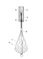
- FIG. 4 is a diagram illustrating a state in which the basket portion 20 has a shorter overall length than the reference shape of FIG. 2 due to an external force applied to the basket portion 20 in a state where the basket portion 20 protrudes from the distal end of the sheath 60.
- the distal end side is larger than the maximum diameter portion 27 of the basket portion 20 and the proximal end side by the luminal tissue.
- Such a shape can be obtained when a pressing force is applied.
- the tip 30 moves to a position closer to the binding portion 40 than in the reference shape.
- a force that moves in the proximal direction acts on the support member 50, and the proximal end portion 51 of the support member 50 approaches the first connecting portion 12. Since the base end portion 51 of the support member 50 is fixed to the connection member 80, the connection member 80 moves relative to the base end side with respect to the second operation wire portion 13 in the insertion hole 81 and moves to the second connection portion 15. Get closer to. That is, the base end portion 51 of the support member 50 moves to the base end side while maintaining a state of being aligned in parallel with the second operation wire portion 13 as the overall length of the basket portion 20 decreases.
- the support member 50 functions as a core material that supports the basket portion 20 so as to keep the tip 30 positioned on the central axis L of the basket portion 20. For this reason, in the basket portion 20, the state in which the tip 30 is positioned on the central axis L is maintained by the support member 50, and the state in which a space is formed in the basket portion 20 is maintained.
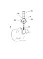
- FIG. 1 is a diagram showing how the treatment tool 1 and the endoscope apparatus 100 are used.
- the treatment tool 1 according to the present embodiment is used by being inserted into an endoscope insertion portion 101 of an endoscope apparatus 100 as shown in FIG.
- the operator inserts the endoscope insertion portion 101 of the endoscope apparatus 100 into the digestive tract from the mouth, for example, and confirms with an imaging unit (not shown) in FIG. 6.
- the distal end of the endoscope insertion portion 101 is inserted up to the duodenum Dd.
- the operator inserts the treatment instrument 1 into the endoscope insertion portion 101 of the endoscope apparatus 100 from the insertion port 103 (see FIG. 5), and moves the distal end portion 62 of the sheath 60 as shown in FIG. It protrudes from the tip of the endoscope insertion portion 101.
- the endoscope operation unit 102 of the endoscope apparatus 100 When projecting the distal end portion 62 of the sheath 60, the endoscope operation unit 102 of the endoscope apparatus 100 is operated, and the sheath 60 is raised by an elevator (not shown) provided in the endoscope insertion unit 101. Let me rise. The operator advances the sheath 60 with respect to the endoscope insertion portion 101 to enter the bile duct BD, and inserts it until the distal end portion 62 of the sheath 60 reaches the vicinity of the calculus T generated in the bile duct BD.
- the operator grasps the grasping portion 74 and pushes the slider 73 toward the distal end side to cause the basket portion 20 to protrude from the distal end portion 62 of the sheath 60.
- the slider 73 is pushed in until the slider 73 comes into contact with the proximal end portion of the operation main body 71, the binding portion 40 protrudes from the distal end portion 62 of the sheath 60.
- the calculus T is located closer to the proximal end side than the maximum diameter portion 27 of the basket portion 20.
- the operator pulls the slider 73 toward the proximal end side to retract the basket portion 20 into the distal end portion 62 of the sheath 60.
- the separation distance between the basket wires 21 is wide at the intake portion 28 on the proximal end side than the maximum diameter portion 27. Therefore, when the calculus T is in contact with the basket wire 21 of the take-in portion 28 and the basket portion 20 is pulled toward the proximal end, the basalt T of the take-up portion 28 is pushed and widened by the calculus T, and the calculus T is It is captured in the part 20.
- the operator moves the slider 73 further to the proximal end side and stores the intake portion 28 in the sheath 60. At this time, the calculus T is held by the plurality of basket wires 21 while being stored in the storage portion 26 of the basket portion 20. Subsequently, the operator retracts the endoscope insertion portion 101, discharges the basket portion 20 outside the body, and discharges the calculus T outside the body to be collected.
- the support member 50 advances and retreats along the second operation wire portion 13 by the connecting member 80.
- the basket portion 20 is supported by the support member 50 while securing an internal space.
- the calculus T is removed from the bile duct BD by the series of procedures described above.
- a calculus T larger than the opening of the duodenal papilla Dp is stored in the basket portion 20
- the treatment tool 1 is incarcerated in the bile duct BD, and the basket portion 20 is It cannot be pulled into the duodenum Dd side.
- a treatment using a calculus crusher as disclosed in Patent Document 2 is performed.
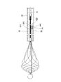
- the operator cuts the sheath 60 and the operation wire 10 at a position in the vicinity of the operation unit 70 (position indicated by an arrow A in FIG. 5), and the endoscope insertion unit 101 and the sheath 60 are disconnected. Remove from the body. When the endoscope insertion portion 101 and the sheath 60 are removed, the operation wire 10 and the support member 50 are exposed in the duodenum Dd as shown in FIG. At this time, in the conventional treatment instrument, since the base end portion of the support member is not connected to the operation wire, it extends substantially linearly by its own rigidity independently of the bending of the operation wire. On the other hand, in the present embodiment, since the base end portion 51 of the support member 50 is connected along the second operation wire portion 13 by the connection member 80, the support member 50 follows the curvature of the second operation wire portion 13. And curved.
- the surgeon inserts the proximal end portion of the cut operation wire 10 that is outside the mouth of the patient P into the coil sheath 201 of the calculus crusher 200, and the coil sheath 201 is inserted. Insert into the body. The coil sheath 201 is inserted along the operation wire 10 to the duodenum Dd and the duodenal papilla Dp, and is inserted until it reaches the basket portion 20 as shown in FIG.
- the surgeon can connect the proximal end portion of the support member 50 as shown in FIG. 51 can be smoothly inserted into the coil sheath 201 together with the second operation wire portion 13.
- the surgeon inserts the cut proximal end portion of the operation wire 10 into the insertion hole (not shown) of the winding shaft 203 of the operation unit 202 of the calculus crusher 200.
- the handle 204 is rotated, the winding shaft 203 is rotated, and the operation wire 10 is wound.
- the operation wire 10 is pulled to the proximal end side, and a force drawn into the coil sheath 201 acts on the basket portion 20, and the calculus T is sandwiched by the basket portion 20.
- the calculus T is clamped and pulverized by the plurality of basket wires 21.
- the calculus T is crushed, the incarceration is eliminated, so the coil sheath 201 and the cut treatment tool 1 are removed from the body.
- the treatment instrument 1 is connected to the operation wire 10 in a state in which the proximal end portion 51 of the support member 50 is movable relative to the second operation wire portion 13.
- the support member 50 fulfills the original function of supporting the basket portion 20 during normal use.
- the base end portion 51 of the support member 50 is disposed along the second operation wire portion 13 even after the cut sheath 60 is removed. It can be smoothly inserted into the coil sheath 201 of 200, and the emergency crushing treatment of the calculus T can be performed quickly.
- the base end side of the basket wire 21 is provided with the straight portion 24 on the base end side with respect to the binding portion 40, and the bundle of the straight portion 24 functions as the second operation wire portion 13.
- the bundling portion and the operation wire may be directly connected.
- the operation member 10 is inserted into the through hole 82 on the proximal end side of the connection member 80 from the binding portion, and the connection member 80 and the proximal end portion 51 of the support member 50 are changed with the shape change of the basket portion 20.
- the structure moves relative to the operation wire 10 in the longitudinal direction.
- the basket portion of the present invention is not limited to the shape shown in the above embodiment, and may be any structure as long as it has a basket shape that includes a plurality of basket wires and can capture foreign matter.
- connection member of the present embodiment is not limited to the above-described form, and the base end portion of the support member 50 is the operation wire so that the support member 50 can move relative to the operation wire 10 in the longitudinal direction. 10 may be connected.
- the connection member may be fixed at a predetermined position on the operation wire 10 side according to the length of the support member 50, and the support member 50 may be relatively movable with respect to the connection member.
- the following configurations shown in FIGS. 12 to 23 can be adopted as the connection member.
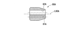
- (First modification of connecting member) 12 and 13 are views showing a first modification of the connection member.
- the insertion hole 81A and the through hole 82A extend in parallel to the central axis L80A of the connection member 80A and are formed near the central axis L80A.
- the second operation wire portion 13 (operation wire 10) and the base end portion of the support member 50 are disposed near the central axis L60 in the sheath 60, and a sufficient gap is provided between the sheath 60 and the lumen. Therefore, the operation wire 10 can be smoothly advanced and retracted with respect to the sheath 60.
- a curved surface is formed at the distal end of the connecting member 80A, and the connecting member 80A can be smoothly advanced and retracted within the lumen of the sheath 60.
- connection member 80A of the present modification is different from the connection member 80 of the first embodiment in that the outer diameter on the base end side is formed smaller than the outer diameter on the distal end side.
- the connecting member 80A has a proximal end side while ensuring a length necessary for stably maintaining the state in which the second operation wire portion 13 (operation wire 10) and the proximal end portion 51 of the support member 50 are parallel to each other.
- the outer diameter is configured to be small.
- connection member 80 ⁇ / b> A of the present modification has the support member 50 and the operation wire 10 in parallel with the base end portion 51 of the support member 50 being along the operation wire 10.
- the base end portion 51 of the support member 50 can be connected to the operation wire 10 so as to be relatively movable in the axial direction while maintaining the operation wire 10.
- the connecting member 80A can smoothly operate the operation wire 10 to advance and retract with respect to the sheath 60 while suppressing sliding resistance with the lumen of the sheath 60.
- the connecting member 80A can be smoothly inserted while suppressing sliding resistance in the coil sheath 201.
- connection member 80B of the present modification includes a substantially cylindrical main body (holding portion) 83B and an insertion tube 85B protruding in the direction of the central axis L80B from the distal end surface 84B of the main body 83B.
- the main body 83B and the insertion tube 85B are integrally formed.
- an insertion hole 81B and a through hole 82B are formed so as to extend in parallel to the central axis L80B of the connecting member 80B and close to the central axis L80B.
- the through hole 82B has an opening diameter that is large enough to allow the second operation wire portion 13 to advance and retreat, and the second operation wire portion 13 is inserted therethrough.
- the insertion hole 81B is formed in communication with the main body portion 83B and the insertion tube 85B.
- the insertion hole 81B has an opening diameter through which the proximal end portion 51 of the support member 50 can be inserted and fixed.
- connection member 80 ⁇ / b> B of the present modification keeps the support member 50 and the operation wire parallel with the base end portion 51 of the support member 50 being along the operation wire 10.
- the base end portion 51 of the support member 50 can be connected to the operation wire 10 so as to be relatively movable in the axial direction.
- the length of the portion of the through hole 82B through which the operation wire 10 is inserted so as to be able to advance and retract is set short in the direction of the central axis L80B. It is possible to reduce the frictional resistance by reducing the contact area.
- the connecting member 80B from obstructing the advance / retreat operation of the operation wire 10 with respect to the sheath 60.
- the insertion hole 81B for fixing the support member 50 is formed in the main body portion 83B and the insertion tube 85B, the state where the operation wire 10 and the base end portion 51 of the support member 50 are in parallel is stably maintained. The necessary length is secured. Since the outer diameter of the insertion tube 85B is smaller than the outer diameter of the main body portion 83B, a sufficient gap is secured between the insertion tube 85B and the lumen of the sheath 60, so that the connection member 80B is the sheath of the operation wire 10. It is possible to prevent the advance / retreat operation for 60 from being hindered.
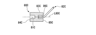
- connection member 80 ⁇ / b> C of this modification is different from the first embodiment in the configuration of the insertion hole through which the operation wire 10 is inserted.
- the connection member 80C has a substantially cylindrical main body (holding portion) 83C and an insertion ring 82C fixed to the main body 83C.
- the main body portion 83C is open to the distal end surface 84C and is formed coaxially with the first insertion hole 81C formed on the central axis L80C of the main body portion 83C and the proximal end surface 85C.
- Second insertion hole 86C Second insertion hole 86C.
- the base end portion 51 of the support member 50 is inserted and fixed in the first insertion hole 81C.
- the insertion ring 82C has a loop portion (sliding portion) 87C formed of a linear member, and the loop portion 87C is bent to be inclined with respect to the end portion.
- the insertion ring 82 ⁇ / b> C is fixed to the main body portion 83 ⁇ / b> C by inserting and fixing the end portion of the linear member through the second insertion hole 86 ⁇ / b> C. As shown in FIGS.
- the loop portion 87C of the insertion ring 82C extends outward from the outer periphery of the main body portion 83C when viewed from the direction orthogonal to the central axis L80C, and the loop extends in the direction of the central axis L80C. It arrange
- the support member 50 and the operation wire 10 are connected by inserting the second operation wire portion 13 through the loop portion 87C of the insertion ring 82C.
- connection member 80 ⁇ / b> C operates while maintaining the support member 50 and the operation wire 10 in parallel with the base end portion 51 of the support member 50 being along the operation wire 10.
- the proximal end portion 51 of the support member 50 can be connected to the wire 10 so as to be relatively movable in the axial direction.
- the second operation wire portion 13 is inserted into the loop portion 87C of the insertion ring 82C formed of a linear member, the contact area between the loop portion 87C and the second operation wire portion 13 is suppressed, and the friction resistance Can be kept low.
- the connection member 80C can be prevented from obstructing the advance / retreat operation of the operation wire 10 with respect to the sheath 60.
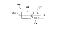
- FIG. 20 is a diagram illustrating a fourth modification of the connection member.
- the connecting member 80D of the present modified example is different from the connecting member 80C of the third modified example in the shape of the loop portion.
- the width (W2) of the loop portion (sliding portion) 87D in the direction orthogonal to the central axis L80D is smaller than the width W1 of the loop portion 87C of the connection member 80C of the third modified example.
- the width W1 of the loop portion 87C of the third modification is substantially equal to the diameter of the main body (holding portion) 83C, whereas the width W2 of the loop portion 87D of this modification is smaller than the diameter of the main body 83D. .
- connection member 80D operates while maintaining the support member 50 and the operation wire 10 in parallel with the base end portion 51 of the support member 50 being along the operation wire 10.
- the proximal end portion 51 of the support member 50 can be connected to the wire 10 so as to be relatively movable in the axial direction.
- the contact area between the loop portion 87D and the second operation wire portion 13 can be suppressed, and the frictional resistance can be suppressed low.
- the connection member 80D can be prevented from obstructing the advance / retreat operation of the operation wire 10 with respect to the sheath 60.
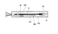
- FIG. 21 is a diagram illustrating a fifth modification of the connection member.
- the connection member 80E of this modification is different from the connection member 80C of the third modification in the shapes of the loop portion 87E, the main body 83E, and the connection portion.
- a linear portion 871 having a predetermined length (for example, 20 mm) is provided between the loop portion (sliding portion) 87E and the main body portion 83E, so that the loop portion 87E and the main body portion 83E are provided. It is configured to have a certain distance.
- the length of the straight line portion 871 may be set so that the distance between the loop portion 87E and the main body portion 83E is long as long as the sliding of the loop portion 87E and the basket portion 20 is not affected. In this modification, the length of the straight line portion 871 is set longer than the length of the loop portion 87E and the main body portion 83E. As shown in FIG. 22, the loop portion 87E and the straight portion 871 form a large-diameter loop in the middle portion of the wire, and at least a portion 872 of the wire of the straight portion 871 is fixed by brazing or adhesive. It is formed with.
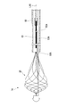
- the basket wire 21 Normally, when the operation wire is pulled in a state where the sheath 60 in the vicinity of the connecting member is curved, the basket wire 21 approaches the inside of the sheath 60 on the proximal side of the curved portion of the sheath 60 as shown in FIG. . On the other hand, a force for returning to the central axis side of the sheath 60 acts on the loop portion. Due to this behavior, the basket wire 21 receives a force in the direction of arrow F1 from the loop portion 87E. Further, the basket wire 21 approaches the outer side of the bending of the sheath 60 on the distal end side of the sheath bending portion, while the main body portion 83E tries to return to the central axis side of the sheath 60.
- FIG. 24 is a partial cross-sectional view showing the distal end portion of the treatment instrument 1A.
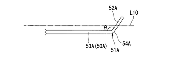
- FIG. 25 is a side view of the base end portion 51A of the support member 50A of the present embodiment.
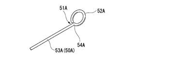
- FIG. 26 is a view of the support member 50A according to the present embodiment as viewed from the distal end side.
- FIG. 27 is a perspective view of the base end portion 51A of the support member 50A of the present embodiment.
- the treatment instrument 1A of the present embodiment has a loop portion (sliding portion) 52A at the base end portion 51A of the support member 50A instead of the connection member 80 of the first embodiment. That is, as shown in FIG. 27, the support member 50 ⁇ / b> A forms a loop part 52 ⁇ / b> A wound around the base end part 51 ⁇ / b> A, and the loop part 52 ⁇ / b> A functions as an insertion path for the operation wire 10.
- a bent portion 54A is provided between the linear portion 53A and the loop portion 52A of the support member 50A, and the loop portion 52A has a support member when viewed from a direction orthogonal to the axial direction as shown in FIG. It arrange
- the angle ⁇ of the bent portion 54A may be a right angle.
- the angle ⁇ of the bent portion 54A is an obtuse angle
- the size in the direction perpendicular to the axis of the base end portion 51A of the support member 50A can be reduced.
- the overall diameter of the support member 50A and the operation wire 10 in a state where the operation wire 10 is inserted can be reduced. Therefore, when the angle ⁇ of the bent portion 54A is an obtuse angle, the support member 50A and the operation wire 10 can be smoothly moved in the sheath 60.
- loop portion 52A is not limited to the above form as long as the operation wire 10 can be inserted.
- a loop portion (sliding portion) 52B may be wound in multiple (double in the example shown in FIG. 28).
- the curved shape of the loop portion is not limited to a circular shape.
- the support member 50 and the operation wire 10 are kept parallel to each other with the base end portion 51 of the support member 50 being along the operation wire, while the operation wire 10 is kept in parallel.
- the base end portion 51 of the support member 50 can be connected so as to be relatively movable in the axial direction.
- the support member 50 and the operation wire 10 can be connected with a simple configuration in which the loop portion 52A is formed at the base end portion 51A of the support member 50A.
Abstract
An endoscopic treatment instrument according to the present invention is provided with: an operation wire retractably inserted into a flexible sheath; a basket part positioned on the distal side of the operation wire; a distal chip that secures distal ends of a plurality of basket wires in a bundle at the distal end of the basket part; a binding part that secures proximal portions of the basket wires in a bundle; and a support member that is disposed to pass through the basket part in the direction along the central axis of the basket part and has a distal portion secured to the distal chip. The support member has a proximal portion positioned more proximal than the binding part and connected to the operation wire so as to be able to slide relative to the operational wire in the direction along the center axis.
Description
本発明は、体内の異物を回収する内視鏡用処置具に関する。本願は、2015年5月19日に、日本に出願された特願2015-101766号に基づき優先権を主張し、その内容をここに援用する。
The present invention relates to an endoscopic treatment tool that collects foreign substances in the body. This application claims priority on May 19, 2015 based on Japanese Patent Application No. 2015-101766 filed in Japan, the contents of which are incorporated herein by reference.
従来、経内視鏡的に体内に挿入され、胆道などの体内に発生した結石などの異物を回収する内視鏡用処置具が知られている。例えば、特許文献1には、螺旋形状の複数の弾性ワイヤからなるバスケット部を備え、バスケット部内に結石を収容して回収する内視鏡用処置具が開示されている。特許文献1に記載された内視鏡用処置具には、バスケット部全体が曲がって倒れることを防止するために、バスケット部に支持部材が設けられている。支持部材は、先端がバスケット部の先端に固定されてバスケット部内に配置され、近位端はバスケット部の近位部分に沿うように配置されて可撓性シース内に挿入されている。
2. Description of the Related Art Conventionally, an endoscopic treatment tool is known which is inserted into a body transendoscopically and collects foreign substances such as stones generated in the body such as the biliary tract. For example, Patent Document 1 discloses an endoscopic treatment tool that includes a basket portion made of a plurality of spiral elastic wires, and stores and collects stones in the basket portion. In the endoscope treatment tool described in Patent Document 1, a support member is provided on the basket portion in order to prevent the entire basket portion from bending and falling down. The support member has a tip fixed to the tip of the basket portion and is disposed in the basket portion, and a proximal end is disposed along the proximal portion of the basket portion and is inserted into the flexible sheath.
このようなバスケット部を有する内視鏡用処置具を用いて大きな結石を回収する際、例えば、結石を収容したバスケット部の大きさと管腔の大きさとの関係で、バスケット部が胆管内で引っ掛かり、バスケット部が胆管内で進退不能となる嵌頓が発生する場合がある。嵌頓が生じた場合、特許文献2に開示の結石粉砕装置を用いて、バスケット部内の結石を粉砕する処置(緊急粉砕)が行われる。特許文献2に開示の結石粉砕装置では、嵌頓が生じた場合、体外に露出する処置具の操作ワイヤの基端部を切断した後、バスケット部内に結石が収容された状態の処置具が挿通されている可撓性シース及び内視鏡を体内から抜去する。次に、結石粉砕装置のコイルシースを処置具の操作ワイヤの切断部に被せながらコイルシースを体内に挿入してバスケット部の基端まで到達させる。その後、コイルシースの基端側で操作ワイヤの切断部を巻き取ることにより、バスケット部をコイルシース内に引き込むと、バスケット部のワイヤが結石を強く締め付けて結石を粉砕する。粉砕により結石が小さく砕かれると、胆管内からバスケット部を抜去できる。
When collecting a large calculus using an endoscope treatment tool having such a basket portion, for example, the basket portion is caught in the bile duct due to the relationship between the size of the basket portion containing the calculus and the size of the lumen. In some cases, the basket portion may become stuck in the bile duct. When incarceration occurs, a treatment (emergency pulverization) for pulverizing the calculus in the basket portion is performed using the calculus crushing device disclosed in Patent Document 2. In the calculus crushing device disclosed in Patent Document 2, when incarceration occurs, the treatment tool in a state where the calculus is accommodated in the basket portion is inserted after cutting the proximal end portion of the operation wire of the treatment tool exposed outside the body. The flexible sheath and endoscope that have been removed are removed from the body. Next, the coil sheath is inserted into the body while reaching the proximal end of the basket portion while covering the cutting portion of the operation wire of the treatment tool with the coil sheath of the calculus crusher. Thereafter, by winding the cut portion of the operation wire on the proximal end side of the coil sheath, when the basket portion is drawn into the coil sheath, the wire in the basket portion strongly tightens the stone and crushes the stone. When the stone is crushed by grinding, the basket can be removed from the bile duct.
特許文献1に開示の内視鏡用処置具を用いて処置を行う際に、特許文献2に開示の結石粉砕装置等を用いる場合、可撓性シースが抜去されているため、バスケット部の支持部材の近位端が胆管内に露出する。特に、バスケット部内に大きい結石が収容されている場合、バスケット部が径方向に拡開しており、支持部材の基端部はバスケット部の基端のワイヤ収束部よりも離れて位置する場合がある。このため、結石粉砕装置のコイルシースの先端開口内に支持部材を収容し難い場合や、収容できない場合がある。このような場合、バスケット部の形状が所望の状態から変化して粉砕能力が低下したり、結石破砕処置の動作の妨げとなる。
When performing treatment using the endoscope treatment tool disclosed in Patent Document 1, when using the calculus crusher disclosed in Patent Document 2, the flexible sheath has been removed, so that the basket portion is supported. The proximal end of the member is exposed in the bile duct. In particular, when a large calculus is accommodated in the basket portion, the basket portion is expanded in the radial direction, and the base end portion of the support member may be located away from the wire converging portion at the base end of the basket portion. is there. For this reason, it may be difficult to accommodate the support member in the distal end opening of the coil sheath of the calculus crushing device, or it may not be accommodated. In such a case, the shape of the basket portion changes from a desired state, so that the pulverization ability is reduced or the operation of the calculus crushing treatment is hindered.
本発明は、上記事情を踏まえ、胆管等の管腔内で嵌頓が生じた場合でも、結石粉砕装置と容易に接続可能であり、緊急粉砕を好適に行うことができる内視鏡用処置具を提供することを目的とする。
In view of the above circumstances, the present invention provides an endoscopic treatment tool that can be easily connected to a calculus crusher and can be suitably urgently crushed even when incarceration occurs in a lumen such as a bile duct. The purpose is to provide.
本発明の第一の態様に係る内視鏡用処置具は、可撓性シースに進退可能に挿通される操作ワイヤと、前記操作ワイヤの先端側に位置し、自然状態で螺旋形状を有する弾性のバスケットワイヤを複数束ねることにより形成されたバスケット部と、前記バスケット部の先端で前記複数のバスケットワイヤの先端を束ねて固定する先端チップと、前記複数のバスケットワイヤの基端部が束ねられて固定される結束部と、前記バスケット部の中心軸に沿って前記バスケット部内を通るように配置され、先端部が前記先端チップに固定された支持部材と、を備え、前記支持部材の基端部は、前記結束部よりも基端側に位置し、且つ、前記操作ワイヤに対して前記中心軸方向に摺動可能に前記操作ワイヤに接続される。
An endoscope treatment tool according to a first aspect of the present invention includes an operation wire that is inserted into a flexible sheath so as to be able to advance and retreat, and an elastic member that is positioned on the distal end side of the operation wire and has a helical shape in a natural state. A basket portion formed by bundling a plurality of basket wires, a tip for bundling and fixing the tips of the basket wires at the tip of the basket portion, and base ends of the basket wires being bundled A bundling portion to be fixed, and a support member that is disposed so as to pass through the basket portion along the central axis of the basket portion, and a distal end portion of which is fixed to the distal end tip, and a base end portion of the support member Is connected to the operation wire so as to be slidable in the central axis direction with respect to the operation wire.
本発明の第二の態様として、第一の態様に係る内視鏡用処置具では、前記複数のバスケットワイヤの前記先端と前記先端チップとの接続部及び前記結束部は前記中心軸上に位置し、前記支持部材は前記中心軸に対して径方向外側にオフセットされた位置に配置されてもよい。
As a second aspect of the present invention, in the endoscope treatment tool according to the first aspect, the connecting portion and the binding portion of the tip of the plurality of basket wires and the tip of the tip are positioned on the central axis. The support member may be disposed at a position offset radially outward with respect to the central axis.
本発明の第三の態様として、第二の態様に係る内視鏡用処置具では、前記支持部材の基端側に設けられ、前記支持部材の前記基端部と前記操作ワイヤとを接続する接続部材をさらに備え、前記接続部材は、前記操作ワイヤに対して摺動可能な摺動部と、前記支持部材の前記基端部を前記中心軸に対してオフセットされた位置に保持する保持部と、を有してもよい。
As a third aspect of the present invention, in the endoscope treatment tool according to the second aspect, provided at the base end side of the support member, the base end portion of the support member and the operation wire are connected. The connecting member further includes a sliding portion that is slidable with respect to the operation wire, and a holding portion that holds the base end portion of the support member at a position offset with respect to the central axis. You may have.
本発明の第四の態様として、第三の態様に係る内視鏡用処置具では、前記接続部材は、パイプ状部材からなり、前記操作ワイヤが挿通される貫通孔と、前記支持部材が挿通される挿通穴とが前記中心軸方向に並んで形成されてもよい。
As a fourth aspect of the present invention, in the endoscope treatment tool according to the third aspect, the connection member is formed of a pipe-shaped member, and the through hole through which the operation wire is inserted and the support member are inserted. The insertion hole to be formed may be formed side by side in the central axis direction.
本発明の第五の態様として、第三の態様に係る内視鏡用処置具では、前記接続部材は、前記支持部材の基端から延出する位置に設けられ、前記操作ワイヤが挿通されるループ部を有してもよい。
As a fifth aspect of the present invention, in the endoscope treatment tool according to the third aspect, the connection member is provided at a position extending from a base end of the support member, and the operation wire is inserted therethrough. You may have a loop part.
本発明の内視鏡用処置具によれば、管腔内で嵌頓が生じた場合でも、結石粉砕装置と容易に接続可能であり、緊急粉砕を好適に行うことができる。
The endoscopic treatment tool of the present invention can be easily connected to a calculus pulverizer even when incarceration occurs in a lumen, and emergency pulverization can be suitably performed.
[第1実施形態]
本発明の第1実施形態に係る内視鏡用処置具(以下、単に「処置具」と称する。)1について説明する。図1は、処置具1の断面図である。図2は、処置具1の先端部の部分断面図である。本実施形態では、処置具1の長さ方向において操作部70が設けられている側を基端側、基端側と反対側を先端側として説明を行う。 [First Embodiment]
An endoscope treatment tool (hereinafter simply referred to as “treatment tool”) 1 according to a first embodiment of the present invention will be described. FIG. 1 is a cross-sectional view of thetreatment instrument 1. FIG. 2 is a partial cross-sectional view of the distal end portion of the treatment instrument 1. In the present embodiment, the side where the operation unit 70 is provided in the length direction of the treatment instrument 1 will be described as the base end side, and the side opposite to the base end side will be described as the front end side.
本発明の第1実施形態に係る内視鏡用処置具(以下、単に「処置具」と称する。)1について説明する。図1は、処置具1の断面図である。図2は、処置具1の先端部の部分断面図である。本実施形態では、処置具1の長さ方向において操作部70が設けられている側を基端側、基端側と反対側を先端側として説明を行う。 [First Embodiment]
An endoscope treatment tool (hereinafter simply referred to as “treatment tool”) 1 according to a first embodiment of the present invention will be described. FIG. 1 is a cross-sectional view of the
処置具1は、図1に示すように、操作ワイヤ10と、バスケット部20と、先端チップ30と、結束部40と、支持部材50とが、可撓性シース(以下、単に「シース」と記す。)60内に進退可能に挿通されて構成されている。
As shown in FIG. 1, the treatment instrument 1 includes an operation wire 10, a basket portion 20, a distal tip 30, a bundling portion 40, and a support member 50, each having a flexible sheath (hereinafter simply referred to as “sheath”). It is configured to be inserted in 60 so as to be able to advance and retreat.
操作ワイヤ10は、基端側が操作部70に接続され、シース60に進退可能に挿通されている。操作ワイヤ10の先端には、バスケット部20が設けられている。操作ワイヤ10は、後述する操作部70の操作により、シース60に対して進退操作される。本実施形態では、操作ワイヤ10としては、複数の金属線材からなる撚り線ワイヤが用いられている。
The operation wire 10 is connected to the operation unit 70 at the proximal end side, and is inserted through the sheath 60 so as to advance and retreat. A basket portion 20 is provided at the tip of the operation wire 10. The operation wire 10 is moved back and forth with respect to the sheath 60 by operation of the operation unit 70 described later. In the present embodiment, a stranded wire made of a plurality of metal wires is used as the operation wire 10.
バスケット部20は、操作ワイヤ10の先端側に位置し、複数のバスケットワイヤ21が束ねられてバスケット状に形成されている。本実施形態では、8本のバスケットワイヤ21によりバスケット部20が構成されているが、結石の取り込み易さや取りこぼしにくさを考慮して適宜バスケットワイヤ21の本数が設定されてよい。
The basket portion 20 is located on the distal end side of the operation wire 10, and a plurality of basket wires 21 are bundled to form a basket shape. In the present embodiment, the basket portion 20 is configured by the eight basket wires 21, but the number of basket wires 21 may be set as appropriate in consideration of ease of taking in stones and difficulty in spilling stones.
複数のバスケットワイヤ21は、それぞれ自然状態で螺旋形状を有し、弾性変形可能な弾性ワイヤである。バスケットワイヤ21は、単線若しくは撚り線の超弾性合金など高い弾性を有する材料によって構成されている。バスケットワイヤ21の材料としては、例えば、ニッケルチタン合金や、ステンレス鋼、ステンレス合金等を採用できる。
The plurality of basket wires 21 are elastic wires each having a spiral shape in a natural state and elastically deformable. The basket wire 21 is made of a highly elastic material such as a single wire or a stranded superelastic alloy. As a material of the basket wire 21, for example, a nickel titanium alloy, stainless steel, a stainless alloy, or the like can be adopted.
バスケットワイヤ21は、長さ方向において全体として螺旋形状を有するが、先端側では螺旋の軸方向のピッチが短く且つ径方向の大きさ(螺旋の巻き径)が大きくなるように形成され、基端側では、先端側に比べて緩やかな螺旋形状が付与されている。
The basket wire 21 has a spiral shape as a whole in the length direction, and is formed so that the pitch in the axial direction of the spiral is short and the size in the radial direction (spiral winding diameter) is large on the distal end side. On the side, a gentle spiral shape is given compared to the tip side.
図1に示すように、各バスケットワイヤ21は、先端部22が先端チップ30に固定され、バスケット部20を構成する部分の第一基端部(基端部)23が結束部40で束ねられている。各バスケットワイヤ21は、自然状態で、先端チップ30と結束部40との間を結ぶ中心軸L周りに螺旋状に巻かれた形状を有し、弾性変形可能に構成されている。バスケット部20の中心軸Lは、バスケットワイヤ21の先端が先端チップ30で束ねられて固定される点と、バスケットワイヤ21の第一基端部23が束ねられた結束部40とを結ぶ線である。各バスケットワイヤ21は、それぞれの螺旋形状の巻き方向が同方向且つ巻き形状が同一であり、中心軸L周りに等間隔に配置されて先端部22及び第一基端部23で束ねられることにより、バスケットが形成される。本実施形態では、バスケットワイヤ21は、先端部22から第一基端部23方向に向かって見たときに、反時計回りに巻かれている。
As shown in FIG. 1, each basket wire 21 has a distal end portion 22 fixed to a distal end tip 30, and a first base end portion (base end portion) 23 constituting the basket portion 20 is bundled by a binding portion 40. ing. Each basket wire 21 has a shape wound spirally around the central axis L connecting the tip 30 and the binding portion 40 in a natural state, and is configured to be elastically deformable. The central axis L of the basket portion 20 is a line connecting the point where the tip of the basket wire 21 is bundled and fixed by the tip 30 and the bundling portion 40 where the first base end portion 23 of the basket wire 21 is bundled. is there. Each basket wire 21 has the same spiral winding direction and the same winding shape, is arranged at equal intervals around the central axis L, and is bundled at the distal end portion 22 and the first proximal end portion 23. A basket is formed. In the present embodiment, the basket wire 21 is wound counterclockwise when viewed from the distal end portion 22 toward the first proximal end portion 23.
本実施形態では、バスケット部20は、外力が掛からない自然状態において、図1及び図2に示すように、バスケット部20の長さ方向の中間部よりも先端部22側に最大径部27が形成され、最大径部27よりも第一基端部23側は、よりピッチが大きい緩やかな螺旋形状となるように形成されている。最大径部27よりも第一基端部23側は、結石等の異物をバスケット部20内に取り込むための取り込み部28として機能する。また、最大径部27よりも先端チップ30側は、バスケット部20内に取り込まれた異物がバスケット部20の外部に脱落し難い収納部26として機能する。
In the present embodiment, in the natural state where no external force is applied, the basket portion 20 has a maximum diameter portion 27 closer to the tip portion 22 side than the intermediate portion in the length direction of the basket portion 20 as shown in FIGS. The first base end portion 23 side of the maximum diameter portion 27 is formed to have a gentle spiral shape with a larger pitch. The first base end portion 23 side with respect to the maximum diameter portion 27 functions as an intake portion 28 for taking in foreign matters such as stones into the basket portion 20. Further, on the tip tip 30 side from the maximum diameter portion 27, the foreign matter taken into the basket portion 20 functions as a storage portion 26 that is difficult to drop out of the basket portion 20.
先端チップ30は、バスケット部20の先端側に設けられ、バスケットワイヤ21の先端部22を束ねて固定している。先端チップ30は、挿入穴(不図示)が形成された筒状部31を有する。筒状部31の挿入穴内に複数のバスケットワイヤ21の先端部22が挿入されて、ロウ付け、溶接、カシメ、樹脂溶着、接着剤及びその組み合わせによって、各バスケットワイヤ21の先端部22が筒状部31に固定されている。筒状部31の先端側には、筒状部31よりも半径の大きい略半球形状の保護部32が設けられている。保護部32は、処置具1の使用時に、生体組織にバスケットワイヤ21の先端部22が刺さったり引っかかったりするのを防止して、バスケット部20を円滑に挿入させる目的で設けられている。先端チップ30の筒状部31には、後述する支持部材50の先端部も挿入されて固定されている。
The tip 30 is provided on the tip side of the basket portion 20, and the tip portion 22 of the basket wire 21 is bundled and fixed. The tip 30 has a cylindrical portion 31 in which an insertion hole (not shown) is formed. The tip portions 22 of the plurality of basket wires 21 are inserted into the insertion holes of the cylindrical portion 31, and the tip portions 22 of the basket wires 21 are formed into a cylindrical shape by brazing, welding, caulking, resin welding, adhesive, and combinations thereof. It is fixed to the part 31. A substantially hemispherical protective portion 32 having a larger radius than the cylindrical portion 31 is provided on the distal end side of the cylindrical portion 31. The protection unit 32 is provided for the purpose of smoothly inserting the basket unit 20 by preventing the tip 22 of the basket wire 21 from being stuck or caught in the living tissue when the treatment instrument 1 is used. A distal end portion of a support member 50 described later is also inserted into and fixed to the cylindrical portion 31 of the distal tip 30.
結束部40は、複数のバスケットワイヤ21の第一基端部23が束ねられて固定される部分である。結束部40としては、ロウ付け、溶接、カシメ、樹脂溶着、接着剤及びその組み合わせによって、各バスケットワイヤ21を互いに固定する構成や、結束部材で複数のバスケットワイヤ21の外周側を包囲して固定する構成が採用できる。本実施形態では、筒状の結束部材41に各バスケットワイヤ21を挿通させて、固定させることにより結束部40を構成している。
The bundling portion 40 is a portion where the first base end portions 23 of the plurality of basket wires 21 are bundled and fixed. The binding portion 40 includes a structure in which the basket wires 21 are fixed to each other by brazing, welding, caulking, resin welding, adhesive, and a combination thereof, and the outer peripheral side of the plurality of basket wires 21 is surrounded and fixed by a binding member. The structure to do can be adopted. In the present embodiment, the binding portion 40 is configured by inserting and fixing each basket wire 21 through the cylindrical binding member 41.
複数のバスケットワイヤ21は、図2に示すように、結束部40よりも基端側、すなわち、第一基端部23よりも基端側に、自然状態で直線形状を有する直線部24を有する。
各バスケットワイヤ21の直線部24は、束ねられた状態で互いに固定されずに、操作ワイヤ10の軸線方向に延びて設けられ、基端25が操作ワイヤ10の先端部11と接続される。操作ワイヤ10とバスケットワイヤ21の基端25とは、それぞれ略筒状の第一連結部12内に挿通されて固定されている。各バスケットワイヤ21の直線部24は、バスケット部20を構成せず、操作ワイヤ10の進退動作に追従して進退する第二操作ワイヤ部(操作ワイヤ)13として機能する。すなわち、バスケットワイヤ21は、先端部22から第一基端部23までがバスケット部20を構成し、結束部40より基端側の直線部24は、第二操作ワイヤ部13を構成する。 As shown in FIG. 2, the plurality ofbasket wires 21 have a linear portion 24 having a linear shape in a natural state on the proximal end side of the binding portion 40, that is, on the proximal end side of the first proximal end portion 23. .
Thestraight portions 24 of the basket wires 21 are not fixed to each other in a bundled state but are provided to extend in the axial direction of the operation wire 10, and the base end 25 is connected to the distal end portion 11 of the operation wire 10. The operation wire 10 and the base end 25 of the basket wire 21 are respectively inserted and fixed in the substantially cylindrical first connecting portion 12. The linear portion 24 of each basket wire 21 does not constitute the basket portion 20 and functions as a second operation wire portion (operation wire) 13 that advances and retracts following the advance and retreat operation of the operation wire 10. That is, in the basket wire 21, the tip portion 22 to the first base end portion 23 constitute the basket portion 20, and the straight portion 24 on the base end side from the binding portion 40 constitutes the second operation wire portion 13.
各バスケットワイヤ21の直線部24は、束ねられた状態で互いに固定されずに、操作ワイヤ10の軸線方向に延びて設けられ、基端25が操作ワイヤ10の先端部11と接続される。操作ワイヤ10とバスケットワイヤ21の基端25とは、それぞれ略筒状の第一連結部12内に挿通されて固定されている。各バスケットワイヤ21の直線部24は、バスケット部20を構成せず、操作ワイヤ10の進退動作に追従して進退する第二操作ワイヤ部(操作ワイヤ)13として機能する。すなわち、バスケットワイヤ21は、先端部22から第一基端部23までがバスケット部20を構成し、結束部40より基端側の直線部24は、第二操作ワイヤ部13を構成する。 As shown in FIG. 2, the plurality of
The
支持部材50は、バスケットワイヤ21よりも剛性が高く、弾性を有する線材であり、図1及び図2に示すように、バスケット部20の中心軸Lに沿ってバスケット部20内を通るように配置されている。図2に示すように、バスケット部20の中心軸Lは、操作ワイヤ10の中心軸L10と略同軸上に配置される。支持部材50の先端は、先端チップ30の筒状部31に固定されている。支持部材50の長さは、バスケット部20がシース60の先端から最大限に突出している状態であっても支持部材50の基端がシース60内に位置する長さに設定されている。支持部材50は、自身の中心軸がバスケット部20及び先端チップ30の中心軸と一致せず、且つバスケット部20の中心軸Lと略平行となるように配置されている。すなわち、支持部材50は、筒状部31における複数のバスケットワイヤ21の固定部よりも径方向外側で筒状部31に固定され、バスケット部20の中心軸Lに対してオフセットされた位置に保持されている。支持部材50は、先端チップ30がバスケット部20の中心軸L上に位置した状態を保つようにバスケット部20を支持している。支持部材50は、シース60への収納時に、シース60の曲げ等の湾曲動作に追従して湾曲可能な程度の剛性を有する。
The support member 50 is a wire having higher rigidity and elasticity than the basket wire 21 and is disposed so as to pass through the basket portion 20 along the central axis L of the basket portion 20 as shown in FIGS. 1 and 2. Has been. As shown in FIG. 2, the central axis L of the basket portion 20 is arranged substantially coaxially with the central axis L <b> 10 of the operation wire 10. The distal end of the support member 50 is fixed to the cylindrical portion 31 of the distal tip 30. The length of the support member 50 is set such that the base end of the support member 50 is located in the sheath 60 even when the basket portion 20 protrudes from the distal end of the sheath 60 to the maximum extent. The support member 50 is arranged so that its own central axis does not coincide with the central axis of the basket portion 20 and the tip 30 and is substantially parallel to the central axis L of the basket portion 20. That is, the support member 50 is fixed to the cylindrical portion 31 on the radially outer side of the fixing portion of the plurality of basket wires 21 in the cylindrical portion 31 and is held at a position offset with respect to the central axis L of the basket portion 20. Has been. The support member 50 supports the basket portion 20 so as to keep the tip 30 positioned on the central axis L of the basket portion 20. The support member 50 has such a rigidity that it can be bent following a bending operation such as bending of the sheath 60 when stored in the sheath 60.
支持部材50の基端部51は結束部40よりも基端側に配置されている。基端部51は、結束部40よりも基端側の位置で、操作ワイヤ10に対してその中心軸L10方向に摺動可能に操作ワイヤ10に接続される。具体的には、支持部材50の基端部51は、接続部材80を介して操作ワイヤ10に接続される。支持部材50は、第二操作ワイヤ部13および操作ワイヤ10には固定されておらず、シース60のルーメン内でバスケットワイヤ21および操作ワイヤ10とは独立してシース60の長手方向に進退する。
The proximal end portion 51 of the support member 50 is disposed on the proximal end side with respect to the binding portion 40. The proximal end portion 51 is connected to the operation wire 10 so as to be slidable in the direction of the central axis L10 with respect to the operation wire 10 at a position closer to the proximal end than the binding portion 40. Specifically, the base end portion 51 of the support member 50 is connected to the operation wire 10 via the connection member 80. The support member 50 is not fixed to the second operation wire portion 13 and the operation wire 10, and moves forward and backward in the longitudinal direction of the sheath 60 independently of the basket wire 21 and the operation wire 10 within the lumen of the sheath 60.
接続部材80は、図2に示すように、略筒状の部材であり、支持部材50が挿入される挿通穴81と、第二操作ワイヤ部13が挿通される貫通孔82とが形成されている。挿通穴81と貫通孔82とは、バスケット部20の中心軸L方向に延びている。挿通穴81と貫通孔82とは平行に並んで形成されている。貫通孔82は、第二操作ワイヤ部13を構成する複数のバスケットワイヤ21の束の外径よりも大きい開口径を有し、貫通孔82内を第二操作ワイヤ部13が進退可能に挿通されている。挿通穴81内には支持部材50の基端部51が挿通されて、ロウ付けや溶接、カシメ、樹脂溶着、接着剤及びその組み合わせによって固定されている。挿通穴81ならびに貫通孔82に支持部材50及び操作ワイヤが挿通されることにより、結束部40よりも基端側において支持部材50が操作ワイヤに沿い、且つ、互いの離間距離を保つことができる。
As shown in FIG. 2, the connection member 80 is a substantially cylindrical member, and is formed with an insertion hole 81 into which the support member 50 is inserted and a through hole 82 into which the second operation wire portion 13 is inserted. Yes. The insertion hole 81 and the through hole 82 extend in the direction of the central axis L of the basket portion 20. The insertion hole 81 and the through hole 82 are formed in parallel. The through hole 82 has an opening diameter larger than the outer diameter of the bundle of the plurality of basket wires 21 constituting the second operation wire portion 13, and the second operation wire portion 13 is inserted into the through hole 82 so as to be able to advance and retract. ing. The base end portion 51 of the support member 50 is inserted into the insertion hole 81 and is fixed by brazing, welding, caulking, resin welding, adhesive, or a combination thereof. By inserting the support member 50 and the operation wire into the insertion hole 81 and the through hole 82, the support member 50 can be along the operation wire on the proximal end side with respect to the binding portion 40 and can be kept away from each other. .
シース60は、内視鏡挿入部101(図5)に挿入される。シース60は、フッ素樹脂や熱可塑性エラストマーなどの公知の樹脂材料や、金属線材を巻き回して形成されるコイルシースや金属線を用いたブレードなどを適宜選択し、または組み合わせて構成することができる。バスケット部20の中心軸Lは、シース60の中心軸L60と、少なくとも平行に配置され、より好ましくは、バスケット部20の中心軸Lが、シース60の中心軸L60上に配置される。
The sheath 60 is inserted into the endoscope insertion portion 101 (FIG. 5). The sheath 60 can be configured by appropriately selecting or combining known resin materials such as fluororesin and thermoplastic elastomer, a coil sheath formed by winding a metal wire, a blade using a metal wire, and the like. The central axis L of the basket portion 20 is disposed at least in parallel with the central axis L60 of the sheath 60. More preferably, the central axis L of the basket portion 20 is disposed on the central axis L60 of the sheath 60.
操作部70は、図1に示すように、処置具1の基端部に設けられている。操作部70は、操作本体71と、シャフト72とスライダ73とを有する。操作本体71は、シース60の基端側に設けられる。操作本体71には、シース60の軸線方向に貫通する貫通路71aが内部に形成されている。操作本体71は、貫通路71aとシース60の内部とが連通するように、シース60の基端部61と接続されている。シャフト72は、貫通路71aに挿通され、シャフト72の先端は、第二連結部15により操作ワイヤ10の基端14と接続されている。シャフト72の基端は、貫通路71aの基端側から突出してスライダ73と固定されている。スライダ73は、操作者が把持可能な把持部74を有する。シャフト72は、操作本体71に対して、貫通路71a内を進退可能に設けられている。
The operation unit 70 is provided at the proximal end portion of the treatment instrument 1 as shown in FIG. The operation unit 70 includes an operation main body 71, a shaft 72, and a slider 73. The operation main body 71 is provided on the proximal end side of the sheath 60. In the operation main body 71, a through passage 71a penetrating in the axial direction of the sheath 60 is formed inside. The operation main body 71 is connected to the base end portion 61 of the sheath 60 so that the through passage 71a and the inside of the sheath 60 communicate with each other. The shaft 72 is inserted through the through passage 71 a, and the distal end of the shaft 72 is connected to the proximal end 14 of the operation wire 10 by the second connecting portion 15. The base end of the shaft 72 protrudes from the base end side of the through passage 71 a and is fixed to the slider 73. The slider 73 has a grip 74 that can be gripped by the operator. The shaft 72 is provided so as to be able to advance and retreat in the through passage 71 a with respect to the operation main body 71.
操作本体71には、さらに、送液ポート75を有する。送液ポート75は、貫通路71aと連通して形成され、例えば、公知のシリンジやポンプを接続できるように構成されている。貫通路71aは、シャフト72が挿通された状態で、送液可能な開口径を有する。送液ポート75よりも基端側の貫通路71aには、先端側よりも拡径する拡径部71bが形成され、拡径部71bと貫通路71aの先端側との間には段差部71cが形成されている。拡径部71bには、拡径部71bの内周面の形状に沿って筒状に形成された嵌合部材76が、操作本体71の基端側から挿入されて嵌合されている。シャフト72の外周にはOリング77が外装され、Oリング77は、嵌合部材76と段差部71cとの間に配置される。このような構成により、貫通路71aの基端側は水密に保たれる。したがって、貫通路71aと連通する送液ポート75を用いた送液が行われた場合に、貫通路71aの送液ポート75よりも基端側(拡径部71b側)への流体の漏洩を防ぐことができる。
The operation main body 71 further has a liquid feeding port 75. The liquid feeding port 75 is formed so as to communicate with the through passage 71a, and is configured so that, for example, a known syringe or pump can be connected. The through passage 71a has an opening diameter capable of feeding liquid in a state where the shaft 72 is inserted. An enlarged diameter portion 71b having a diameter larger than that of the distal end side is formed in the through passage 71a closer to the proximal end than the liquid feeding port 75, and a step portion 71c is formed between the enlarged diameter portion 71b and the distal end side of the penetration passage 71a. Is formed. A fitting member 76 that is formed in a cylindrical shape along the shape of the inner peripheral surface of the enlarged diameter portion 71 b is inserted and fitted into the enlarged diameter portion 71 b from the proximal end side of the operation main body 71. An O-ring 77 is externally provided on the outer periphery of the shaft 72, and the O-ring 77 is disposed between the fitting member 76 and the stepped portion 71c. With such a configuration, the base end side of the through passage 71a is kept watertight. Therefore, when liquid feeding is performed using the liquid feeding port 75 communicating with the through passage 71a, fluid leakage to the base end side (the enlarged diameter portion 71b side) from the liquid feeding port 75 of the through passage 71a is prevented. Can be prevented.
上記のように構成された処置具1の動作について図2から図4を参照して説明する。図3及び図4は、処置具1の先端部分を示す断面図である。
The operation of the treatment instrument 1 configured as described above will be described with reference to FIGS. 3 and 4 are cross-sectional views showing the distal end portion of the treatment instrument 1.
図2は、バスケット部20がシース60の先端から押し出された状態を示す図である。バスケット部20がシース60の先端から押し出され、且つ、バスケット部20に外力が付与されない状態では、バスケット部20は、バスケットワイヤ21の復元力により図2に示すように予め付与された基本形状のバスケットを形成する。このとき、支持部材50の基端部51は、シース60のルーメン内で、第二操作ワイヤ部13の略中間位置(結束部40と第一連結部12との中間位置)で、接続部材80により第二操作ワイヤ部13に接続されている。
FIG. 2 is a view showing a state in which the basket portion 20 is pushed out from the distal end of the sheath 60. In a state where the basket portion 20 is pushed out from the distal end of the sheath 60 and no external force is applied to the basket portion 20, the basket portion 20 has a basic shape previously applied as shown in FIG. 2 by the restoring force of the basket wire 21. Form a basket. At this time, the base end portion 51 of the support member 50 is connected to the connection member 80 at a substantially intermediate position of the second operation wire portion 13 (an intermediate position between the binding portion 40 and the first connecting portion 12) within the lumen of the sheath 60. Is connected to the second operation wire portion 13.
バスケット部20は、上述した螺旋形状のバスケットワイヤ21により構成されているので、シース60から突出したときは、異物を捕捉しやすく、且つ保持しやすいバスケット形状が形成される。さらに、バスケット部20がシース60内に引き込まれるときは、円滑に縮径してシース60内に容易に収納できる。バスケット部20のシース60に対する進退動作時に、支持部材50は、バスケット部20の中心軸Lを、シース60の中心軸L60と平行に保ちながら支持できる。
Since the basket portion 20 is configured by the spiral basket wire 21 described above, when protruding from the sheath 60, a basket shape is formed which is easy to capture and hold foreign matter. Further, when the basket portion 20 is drawn into the sheath 60, the diameter of the basket portion 20 can be reduced smoothly and can be easily stored in the sheath 60. When the basket portion 20 moves back and forth with respect to the sheath 60, the support member 50 can support the central axis L of the basket portion 20 while keeping it parallel to the central axis L60 of the sheath 60.
図3は、バスケット部20がシース60内に収納された状態を示している。バスケット部20がシース60内に収納された状態では、バスケット部20はシース60のルーメンの内壁に押圧されて弾性変形し、図2に示す基本形状よりも縮径される。バスケット部20が縮径すると、相対的にバスケット部20の全長は中心軸L方向に延び、先端チップ30は結束部40に対して離間する方向に移動する。先端チップ30の結束部40から離間する方向への移動に伴って支持部材50が先端側に牽引され、バスケット部20内に配置されている部分の長さが増大する。
FIG. 3 shows a state where the basket portion 20 is stored in the sheath 60. In a state in which the basket portion 20 is housed in the sheath 60, the basket portion 20 is pressed against the inner wall of the lumen of the sheath 60 and elastically deformed, and the diameter thereof is reduced from the basic shape shown in FIG. When the diameter of the basket portion 20 is reduced, the overall length of the basket portion 20 relatively extends in the direction of the central axis L, and the tip 30 moves in a direction away from the binding portion 40. As the tip tip 30 moves away from the binding portion 40, the support member 50 is pulled toward the tip side, and the length of the portion disposed in the basket portion 20 increases.
このとき、支持部材50の基端部51は接続部材80に固定されているので、接続部材80は、貫通孔82において第二操作ワイヤ部13に対して先端側に相対移動して結束部40に近付く。すなわち、支持部材50の基端部51は、バスケット部20の縮径に伴って、第二操作ワイヤ部13に沿い、且つ、平行に並んだ状態を保ちつつ、先端側に移動する。このとき、支持部材50は、先端チップ30がバスケット部20の中心軸L上に位置する状態を保ち、バスケット部20を支持する心材として機能する。このため、複数のバスケットワイヤ21は支持部材50に沿って略直線状に弾性変形された状態でシース60内に収納される。
At this time, since the base end portion 51 of the support member 50 is fixed to the connection member 80, the connection member 80 moves relative to the distal end side with respect to the second operation wire portion 13 in the through hole 82, and the binding portion 40. Get closer to. That is, the base end portion 51 of the support member 50 moves toward the distal end side while maintaining a state of being aligned along the second operation wire portion 13 and parallel to the diameter of the basket portion 20. At this time, the support member 50 functions as a core material that supports the basket portion 20 while keeping the tip 30 positioned on the central axis L of the basket portion 20. For this reason, the plurality of basket wires 21 are accommodated in the sheath 60 in a state of being elastically deformed substantially linearly along the support member 50.
図4は、バスケット部20がシース60の先端から突出した状態で、バスケット部20に外力が加わることにより、バスケット部20が図2の基準形状よりも全長が短くなった状態を示す図である。例えば、処置具1を管腔内に挿入された状態で、操作ワイヤ10を基端側に牽引した際、バスケット部20の最大径部27よりも先端側に、管腔組織により基端側に押される力が作用した場合に、このような形状になり得る。バスケット部20が図4に示す状態となった場合、先端チップ30は、基準形状時よりも結束部40に近い位置に移動する。このとき、支持部材50には基端方向に移動する力が作用し、支持部材50の基端部51は第一連結部12に近付く。支持部材50の基端部51は接続部材80に固定されているので、接続部材80は、挿通穴81において第二操作ワイヤ部13に対して基端側に相対移動して第二連結部15に近付く。すなわち、支持部材50の基端部51は、バスケット部20の全長の減少に伴って、第二操作ワイヤ部13に沿い、且つ、平行に並んだ状態を保ちつつ、基端側に移動する。
FIG. 4 is a diagram illustrating a state in which the basket portion 20 has a shorter overall length than the reference shape of FIG. 2 due to an external force applied to the basket portion 20 in a state where the basket portion 20 protrudes from the distal end of the sheath 60. . For example, when the operation wire 10 is pulled to the proximal end side with the treatment instrument 1 being inserted into the lumen, the distal end side is larger than the maximum diameter portion 27 of the basket portion 20 and the proximal end side by the luminal tissue. Such a shape can be obtained when a pressing force is applied. When the basket portion 20 is in the state shown in FIG. 4, the tip 30 moves to a position closer to the binding portion 40 than in the reference shape. At this time, a force that moves in the proximal direction acts on the support member 50, and the proximal end portion 51 of the support member 50 approaches the first connecting portion 12. Since the base end portion 51 of the support member 50 is fixed to the connection member 80, the connection member 80 moves relative to the base end side with respect to the second operation wire portion 13 in the insertion hole 81 and moves to the second connection portion 15. Get closer to. That is, the base end portion 51 of the support member 50 moves to the base end side while maintaining a state of being aligned in parallel with the second operation wire portion 13 as the overall length of the basket portion 20 decreases.
図4に示す状態の場合、支持部材50は、先端チップ30がバスケット部20の中心軸L上に位置する状態を保つようにバスケット部20を支持する心材として機能する。このため、バスケット部20は、支持部材50によって先端チップ30が中心軸L上に位置する状態が保たれ、バスケット部20内に空間が形成される状態が保たれる。
4, the support member 50 functions as a core material that supports the basket portion 20 so as to keep the tip 30 positioned on the central axis L of the basket portion 20. For this reason, in the basket portion 20, the state in which the tip 30 is positioned on the central axis L is maintained by the support member 50, and the state in which a space is formed in the basket portion 20 is maintained.
次に、処置具1を用いた手技について説明する。以下では、胆管BD内に生じた結石などの異物を取り除く手技を例に説明する。図5から図11は、処置具1及び内視鏡装置100の使用態様を示す図である。本実施形態に係る処置具1は、図5に示すように、内視鏡装置100の内視鏡挿入部101に挿入して使用される。
Next, a procedure using the treatment tool 1 will be described. Hereinafter, a procedure for removing foreign matters such as stones generated in the bile duct BD will be described as an example. 5 to 11 are diagrams showing how the treatment tool 1 and the endoscope apparatus 100 are used. The treatment tool 1 according to the present embodiment is used by being inserted into an endoscope insertion portion 101 of an endoscope apparatus 100 as shown in FIG.
まず、操作者は、図5に示すように、内視鏡装置100の内視鏡挿入部101を、例えば、口から消化管内へ挿入し、不図示の撮像手段で確認しながら、図6に示すように、内視鏡挿入部101の先端を十二指腸Ddまで挿入する。続いて、操作者は、処置具1を挿入口103(図5参照)から内視鏡装置100の内視鏡挿入部101に挿入し、図6に示すように、シース60の先端部62を内視鏡挿入部101の先端から突出させる。シース60の先端部62を突出させる際、内視鏡装置100の内視鏡操作部102を操作して、内視鏡挿入部101内に設けられた起上台(不図示)によりシース60を起上させる。操作者は、内視鏡挿入部101に対してシース60を前進させて胆管BD内に進入させ、シース60の先端部62が胆管BD内に生じている結石Tの近傍に達するまで挿入する。
First, as shown in FIG. 5, the operator inserts the endoscope insertion portion 101 of the endoscope apparatus 100 into the digestive tract from the mouth, for example, and confirms with an imaging unit (not shown) in FIG. 6. As shown, the distal end of the endoscope insertion portion 101 is inserted up to the duodenum Dd. Subsequently, the operator inserts the treatment instrument 1 into the endoscope insertion portion 101 of the endoscope apparatus 100 from the insertion port 103 (see FIG. 5), and moves the distal end portion 62 of the sheath 60 as shown in FIG. It protrudes from the tip of the endoscope insertion portion 101. When projecting the distal end portion 62 of the sheath 60, the endoscope operation unit 102 of the endoscope apparatus 100 is operated, and the sheath 60 is raised by an elevator (not shown) provided in the endoscope insertion unit 101. Let me rise. The operator advances the sheath 60 with respect to the endoscope insertion portion 101 to enter the bile duct BD, and inserts it until the distal end portion 62 of the sheath 60 reaches the vicinity of the calculus T generated in the bile duct BD.
続いて、操作者は、把持部74を把持してスライダ73を先端側に押し込み、シース60の先端部62からバスケット部20を突出させる。スライダ73が操作本体71の基端部に当接するまでスライダ73を押し込むと、結束部40がシース60の先端部62から突出する。このとき、図6に示すように、結石Tがバスケット部20の最大径部27よりも基端側に位置する。
Subsequently, the operator grasps the grasping portion 74 and pushes the slider 73 toward the distal end side to cause the basket portion 20 to protrude from the distal end portion 62 of the sheath 60. When the slider 73 is pushed in until the slider 73 comes into contact with the proximal end portion of the operation main body 71, the binding portion 40 protrudes from the distal end portion 62 of the sheath 60. At this time, as shown in FIG. 6, the calculus T is located closer to the proximal end side than the maximum diameter portion 27 of the basket portion 20.
続いて、操作者は、スライダ73を基端側に牽引して、バスケット部20をシース60の先端部62内に後退させる。バスケット部20は、最大径部27よりも基端側の取り込み部28では、各バスケットワイヤ21の離間距離が広い。そのため、結石Tが取り込み部28のバスケットワイヤ21に当接した状態で、バスケット部20を基端側に引き込むと、結石Tによって取り込み部28のバスケットワイヤ21が押し広げられて、結石Tがバスケット部20内に捕捉される。結石Tがバスケット部20内に捕捉されたら、操作者はスライダ73をさらに基端側に移動させて、取り込み部28をシース60内に収納する。このとき、結石Tはバスケット部20の収納部26に収納された状態で、複数のバスケットワイヤ21に保持される。続いて、操作者は、内視鏡挿入部101を後退させて、バスケット部20を体外に排出して、結石Tを体外に排出させて回収する。
Subsequently, the operator pulls the slider 73 toward the proximal end side to retract the basket portion 20 into the distal end portion 62 of the sheath 60. In the basket portion 20, the separation distance between the basket wires 21 is wide at the intake portion 28 on the proximal end side than the maximum diameter portion 27. Therefore, when the calculus T is in contact with the basket wire 21 of the take-in portion 28 and the basket portion 20 is pulled toward the proximal end, the basalt T of the take-up portion 28 is pushed and widened by the calculus T, and the calculus T is It is captured in the part 20. When the calculus T is captured in the basket portion 20, the operator moves the slider 73 further to the proximal end side and stores the intake portion 28 in the sheath 60. At this time, the calculus T is held by the plurality of basket wires 21 while being stored in the storage portion 26 of the basket portion 20. Subsequently, the operator retracts the endoscope insertion portion 101, discharges the basket portion 20 outside the body, and discharges the calculus T outside the body to be collected.
上述した一連の手技の際、支持部材50は、接続部材80により、第二操作ワイヤ部13に沿って進退する。バスケット部20は、支持部材50により、内部空間を確保しながら支持される。
In the series of procedures described above, the support member 50 advances and retreats along the second operation wire portion 13 by the connecting member 80. The basket portion 20 is supported by the support member 50 while securing an internal space.
上述した一連の手技により、結石Tが胆管BDから除去される。しかし、例えば、図7に示すように、十二指腸乳頭Dpの開口よりも大きな結石Tが、バスケット部20内に収納された場合、胆管BD内で処置具1の嵌頓が生じ、バスケット部20を十二指腸Dd側に引き込むことができない。このような場合に、特許文献2に開示されるような結石粉砕装置を用いた処置が行われる。
The calculus T is removed from the bile duct BD by the series of procedures described above. However, for example, as shown in FIG. 7, when a calculus T larger than the opening of the duodenal papilla Dp is stored in the basket portion 20, the treatment tool 1 is incarcerated in the bile duct BD, and the basket portion 20 is It cannot be pulled into the duodenum Dd side. In such a case, a treatment using a calculus crusher as disclosed in Patent Document 2 is performed.
まず、嵌頓が生じた場合、操作者は、シース60及び操作ワイヤ10を操作部70近傍の位置(図5に矢印Aで示す位置)で切断し、内視鏡挿入部101及びシース60を体内から抜去する。内視鏡挿入部101及びシース60が抜去されると、図7に示すように、操作ワイヤ10と、支持部材50とが十二指腸Dd内に露出する。このとき、従来の処置具では、支持部材の基端部は操作ワイヤに接続されないので、自身の剛性により、操作ワイヤの曲げとは独立して、略直線状に延びる。一方、本実施形態では、支持部材50の基端部51は、接続部材80により第二操作ワイヤ部13に沿って接続されているので、支持部材50は第二操作ワイヤ部13の湾曲に追従して湾曲している。
First, when incarceration occurs, the operator cuts the sheath 60 and the operation wire 10 at a position in the vicinity of the operation unit 70 (position indicated by an arrow A in FIG. 5), and the endoscope insertion unit 101 and the sheath 60 are disconnected. Remove from the body. When the endoscope insertion portion 101 and the sheath 60 are removed, the operation wire 10 and the support member 50 are exposed in the duodenum Dd as shown in FIG. At this time, in the conventional treatment instrument, since the base end portion of the support member is not connected to the operation wire, it extends substantially linearly by its own rigidity independently of the bending of the operation wire. On the other hand, in the present embodiment, since the base end portion 51 of the support member 50 is connected along the second operation wire portion 13 by the connection member 80, the support member 50 follows the curvature of the second operation wire portion 13. And curved.
術者は、図8に示すように、患者Pの口の外部に出ている切断された操作ワイヤ10の基端側の部分を、結石粉砕装置200のコイルシース201内に挿入し、コイルシース201を体内に挿入する。コイルシース201は、操作ワイヤ10に沿って十二指腸Dd及び十二指腸乳頭Dpまで挿入され、図9に示すように、バスケット部20に到達するまで挿入される。
As shown in FIG. 8, the surgeon inserts the proximal end portion of the cut operation wire 10 that is outside the mouth of the patient P into the coil sheath 201 of the calculus crusher 200, and the coil sheath 201 is inserted. Insert into the body. The coil sheath 201 is inserted along the operation wire 10 to the duodenum Dd and the duodenal papilla Dp, and is inserted until it reaches the basket portion 20 as shown in FIG.
このとき、支持部材50の基端部51は、接続部材80により第二操作ワイヤ部13に沿って接続されているので、図10に示すように、術者は、支持部材50の基端部51を、第二操作ワイヤ部13と共にコイルシース201内に円滑に挿入することができる。
At this time, since the proximal end portion 51 of the support member 50 is connected along the second operation wire portion 13 by the connection member 80, the surgeon can connect the proximal end portion of the support member 50 as shown in FIG. 51 can be smoothly inserted into the coil sheath 201 together with the second operation wire portion 13.
続いて、図11に示すように、術者は、切断された操作ワイヤ10の基端部分を結石粉砕装置200の操作部202の巻き取り軸203の挿通孔(不図示)に挿入した後、ハンドル204を回転操作して、巻き取り軸203を回転させて操作ワイヤ10を巻きつける。その結果、操作ワイヤ10が基端側に牽引されて、バスケット部20には、コイルシース201内に引き込まれる力が作用し、バスケット部20で結石Tが挟持された状態となる。さらに操作ワイヤ10が巻き取られると、複数のバスケットワイヤ21により結石Tが締め付けられて粉砕する。結石Tが粉砕されると嵌頓が解消するので、コイルシース201及び切断された処置具1を体外に抜去する。
Subsequently, as shown in FIG. 11, the surgeon inserts the cut proximal end portion of the operation wire 10 into the insertion hole (not shown) of the winding shaft 203 of the operation unit 202 of the calculus crusher 200. The handle 204 is rotated, the winding shaft 203 is rotated, and the operation wire 10 is wound. As a result, the operation wire 10 is pulled to the proximal end side, and a force drawn into the coil sheath 201 acts on the basket portion 20, and the calculus T is sandwiched by the basket portion 20. When the operation wire 10 is further wound, the calculus T is clamped and pulverized by the plurality of basket wires 21. When the calculus T is crushed, the incarceration is eliminated, so the coil sheath 201 and the cut treatment tool 1 are removed from the body.
本実施形態に係る処置具1は、支持部材50の基端部51が第二操作ワイヤ部13に対して相対移動可能な状態で、操作ワイヤ10に接続されている。この結果、通常の使用時には、支持部材50は、バスケット部20を支持するという本来の機能を果たす。嵌頓が生じた場合は、切断されたシース60が抜去された後も、支持部材50の基端部51は第二操作ワイヤ部13に沿って配置されるので、支持部材50が結石粉砕装置200のコイルシース201内に円滑に挿入されて、結石Tの緊急破砕処置を迅速に行うことができる。
The treatment instrument 1 according to the present embodiment is connected to the operation wire 10 in a state in which the proximal end portion 51 of the support member 50 is movable relative to the second operation wire portion 13. As a result, the support member 50 fulfills the original function of supporting the basket portion 20 during normal use. When incarceration occurs, the base end portion 51 of the support member 50 is disposed along the second operation wire portion 13 even after the cut sheath 60 is removed. It can be smoothly inserted into the coil sheath 201 of 200, and the emergency crushing treatment of the calculus T can be performed quickly.
本実施形態では、バスケットワイヤ21の基端側は、結束部40よりも基端側に直線部24を設けて、直線部24の束が第二操作ワイヤ部13として機能する例を示したが、結束部と操作ワイヤとが直接接続される構成でもよい。この場合、接続部材80は結束部よりも基端側で、貫通孔82内に操作ワイヤ10が挿通され、接続部材80及び支持部材50の基端部51が、バスケット部20の形状変化に伴って操作ワイヤ10に対して長手方向に相対移動する構成となる。
In the present embodiment, the base end side of the basket wire 21 is provided with the straight portion 24 on the base end side with respect to the binding portion 40, and the bundle of the straight portion 24 functions as the second operation wire portion 13. The bundling portion and the operation wire may be directly connected. In this case, the operation member 10 is inserted into the through hole 82 on the proximal end side of the connection member 80 from the binding portion, and the connection member 80 and the proximal end portion 51 of the support member 50 are changed with the shape change of the basket portion 20. Thus, the structure moves relative to the operation wire 10 in the longitudinal direction.
本発明のバスケット部は、上記実施形態に示す形状に限定されるものではなく、複数のバスケットワイヤで構成され、異物を捕捉可能なバスケット形状を有する構成であればよい。
The basket portion of the present invention is not limited to the shape shown in the above embodiment, and may be any structure as long as it has a basket shape that includes a plurality of basket wires and can capture foreign matter.
本実施形態の接続部材は、上述の形態に限定されるものではなく、支持部材50が操作ワイヤ10に対して長手方向に相対移動可能となるように、支持部材50の基端部が操作ワイヤ10と接続されるものであればよい。例えば、支持部材50の長さに応じて、接続部材を操作ワイヤ10側の所定の位置に固定し、支持部材50が接続部材に対して相対移動可能な構成としてもよい。この他、接続部材は、例えば、図12から図23に示す以下の構成が採用可能である。
The connection member of the present embodiment is not limited to the above-described form, and the base end portion of the support member 50 is the operation wire so that the support member 50 can move relative to the operation wire 10 in the longitudinal direction. 10 may be connected. For example, the connection member may be fixed at a predetermined position on the operation wire 10 side according to the length of the support member 50, and the support member 50 may be relatively movable with respect to the connection member. In addition, for example, the following configurations shown in FIGS. 12 to 23 can be adopted as the connection member.
(接続部材の第1変形例)
図12及び図13は、接続部材の第1変形例を示す図である。図12及び図13に示すように、本変形例の接続部材80Aでは、挿通穴81Aと貫通孔82Aとは、それぞれ接続部材80Aの中心軸L80Aと平行に延び、且つ、中心軸L80A寄りに形成されている。このような構成により、第二操作ワイヤ部13(操作ワイヤ10)及び支持部材50の基端部は、シース60内の中心軸L60付近に配置され、シース60にルーメンとの間に十分な隙間を有するので、シース60に対して操作ワイヤ10の進退が円滑に行える。接続部材80Aの先端側の周端部には曲面が形成され、シース60のルーメン内で円滑に進退できるように形成されている。 (First modification of connecting member)
12 and 13 are views showing a first modification of the connection member. As shown in FIGS. 12 and 13, in theconnection member 80A of the present modification, the insertion hole 81A and the through hole 82A extend in parallel to the central axis L80A of the connection member 80A and are formed near the central axis L80A. Has been. With such a configuration, the second operation wire portion 13 (operation wire 10) and the base end portion of the support member 50 are disposed near the central axis L60 in the sheath 60, and a sufficient gap is provided between the sheath 60 and the lumen. Therefore, the operation wire 10 can be smoothly advanced and retracted with respect to the sheath 60. A curved surface is formed at the distal end of the connecting member 80A, and the connecting member 80A can be smoothly advanced and retracted within the lumen of the sheath 60.
図12及び図13は、接続部材の第1変形例を示す図である。図12及び図13に示すように、本変形例の接続部材80Aでは、挿通穴81Aと貫通孔82Aとは、それぞれ接続部材80Aの中心軸L80Aと平行に延び、且つ、中心軸L80A寄りに形成されている。このような構成により、第二操作ワイヤ部13(操作ワイヤ10)及び支持部材50の基端部は、シース60内の中心軸L60付近に配置され、シース60にルーメンとの間に十分な隙間を有するので、シース60に対して操作ワイヤ10の進退が円滑に行える。接続部材80Aの先端側の周端部には曲面が形成され、シース60のルーメン内で円滑に進退できるように形成されている。 (First modification of connecting member)
12 and 13 are views showing a first modification of the connection member. As shown in FIGS. 12 and 13, in the
また、本変形例の接続部材80Aは、基端側の外径が先端側の外径よりも小さく形成されている点で第1実施形態の接続部材80と相違する。接続部材80Aは、第二操作ワイヤ部13(操作ワイヤ10)と、支持部材50の基端部51とが平行した状態を安定して保つのに必要な長さを確保しつつ、基端側の外径が小さくなるように構成している。
Further, the connection member 80A of the present modification is different from the connection member 80 of the first embodiment in that the outer diameter on the base end side is formed smaller than the outer diameter on the distal end side. The connecting member 80A has a proximal end side while ensuring a length necessary for stably maintaining the state in which the second operation wire portion 13 (operation wire 10) and the proximal end portion 51 of the support member 50 are parallel to each other. The outer diameter is configured to be small.
本変形例の接続部材80Aは、第1実施形態の接続部材80と同様に、支持部材50の基端部51を操作ワイヤ10に沿わせた状態で支持部材50と操作ワイヤ10とを平行に保ちながら、操作ワイヤ10に対して支持部材50の基端部51が軸線方向に相対移動可能に接続することができる。さらに、接続部材80Aは、シース60のルーメンとの摺動抵抗を抑えて、操作ワイヤ10のシース60に対する進退を円滑に操作できる。また、嵌頓が生じてコイルシース201内に挿入される場合にも、接続部材80Aはコイルシース201内での摺動抵抗を抑えて、円滑に挿入することができる。
Similar to the connection member 80 of the first embodiment, the connection member 80 </ b> A of the present modification has the support member 50 and the operation wire 10 in parallel with the base end portion 51 of the support member 50 being along the operation wire 10. The base end portion 51 of the support member 50 can be connected to the operation wire 10 so as to be relatively movable in the axial direction while maintaining the operation wire 10. Further, the connecting member 80A can smoothly operate the operation wire 10 to advance and retract with respect to the sheath 60 while suppressing sliding resistance with the lumen of the sheath 60. In addition, even when the fitting member is inserted and inserted into the coil sheath 201, the connecting member 80A can be smoothly inserted while suppressing sliding resistance in the coil sheath 201.
(接続部材の第2変形例)
図14から図16は、接続部材の第2変形例を示す図である。図14及び図16に示すように、本変形例の接続部材80Bは、略円柱形状の本体部(保持部)83Bと、本体部83Bの先端面84Bから中心軸L80B方向に突出した挿通管85Bとが設けられている点で、第1実施形態の接続部材80と相違する。本体部83Bと挿通管85Bとは一体成形されている。図15に示すように、本体部83Bには、挿通穴81Bと貫通孔82Bとが、それぞれ接続部材80Bの中心軸L80Bと平行に延び、且つ、中心軸L80B寄りに形成されている。貫通孔82Bは、第二操作ワイヤ部13が進退可能な程度の大きさの開口径を有し、第二操作ワイヤ部13が挿通される。挿通穴81Bは、本体部83Bと、挿通管85Bとに連通して形成されている。挿通穴81Bは、支持部材50の基端部51が挿通され固定可能な開口径を有する。このような構成により、第二操作ワイヤ部13(操作ワイヤ10)及び支持部材の基端部は、シース60内の中心軸L60付近に配置され、シース60にルーメンとの間に十分な隙間を有するので、シース60に対して操作ワイヤ10の進退が円滑に行える。
さらに、本体部83B及び挿通管85Bの周端部は曲面が形成され、シース60のルーメン内で円滑に挿通されるように形成されている。 (Second modification of connecting member)
14 to 16 are views showing a second modification of the connection member. As shown in FIGS. 14 and 16, theconnection member 80B of the present modification includes a substantially cylindrical main body (holding portion) 83B and an insertion tube 85B protruding in the direction of the central axis L80B from the distal end surface 84B of the main body 83B. Are different from the connection member 80 of the first embodiment. The main body 83B and the insertion tube 85B are integrally formed. As shown in FIG. 15, in the main body portion 83B, an insertion hole 81B and a through hole 82B are formed so as to extend in parallel to the central axis L80B of the connecting member 80B and close to the central axis L80B. The through hole 82B has an opening diameter that is large enough to allow the second operation wire portion 13 to advance and retreat, and the second operation wire portion 13 is inserted therethrough. The insertion hole 81B is formed in communication with the main body portion 83B and the insertion tube 85B. The insertion hole 81B has an opening diameter through which the proximal end portion 51 of the support member 50 can be inserted and fixed. With such a configuration, the second operation wire portion 13 (operation wire 10) and the base end portion of the support member are disposed near the central axis L60 in the sheath 60, and a sufficient gap is provided between the sheath 60 and the lumen. Therefore, the operation wire 10 can be smoothly advanced and retracted with respect to the sheath 60.
Further, the peripheral end portions of the main body portion 83 </ b> B and the insertion tube 85 </ b> B are curved so as to be smoothly inserted in the lumen of thesheath 60.
図14から図16は、接続部材の第2変形例を示す図である。図14及び図16に示すように、本変形例の接続部材80Bは、略円柱形状の本体部(保持部)83Bと、本体部83Bの先端面84Bから中心軸L80B方向に突出した挿通管85Bとが設けられている点で、第1実施形態の接続部材80と相違する。本体部83Bと挿通管85Bとは一体成形されている。図15に示すように、本体部83Bには、挿通穴81Bと貫通孔82Bとが、それぞれ接続部材80Bの中心軸L80Bと平行に延び、且つ、中心軸L80B寄りに形成されている。貫通孔82Bは、第二操作ワイヤ部13が進退可能な程度の大きさの開口径を有し、第二操作ワイヤ部13が挿通される。挿通穴81Bは、本体部83Bと、挿通管85Bとに連通して形成されている。挿通穴81Bは、支持部材50の基端部51が挿通され固定可能な開口径を有する。このような構成により、第二操作ワイヤ部13(操作ワイヤ10)及び支持部材の基端部は、シース60内の中心軸L60付近に配置され、シース60にルーメンとの間に十分な隙間を有するので、シース60に対して操作ワイヤ10の進退が円滑に行える。
さらに、本体部83B及び挿通管85Bの周端部は曲面が形成され、シース60のルーメン内で円滑に挿通されるように形成されている。 (Second modification of connecting member)
14 to 16 are views showing a second modification of the connection member. As shown in FIGS. 14 and 16, the
Further, the peripheral end portions of the main body portion 83 </ b> B and the insertion tube 85 </ b> B are curved so as to be smoothly inserted in the lumen of the
本変形例の接続部材80Bは、第1実施形態の接続部材80と同様に、支持部材50の基端部51を操作ワイヤ10に沿わせた状態で支持部材50と操作ワイヤとを平行に保ちながら、操作ワイヤ10に対して支持部材50の基端部51が軸線方向に相対移動可能に接続することができる。さらに、本変形例の接続部材80Bは、操作ワイヤ10が進退可能に挿通される貫通孔82Bの部分の、中心軸L80B方向の長さが短く設定されているので、操作ワイヤ10と貫通孔82Bとの接触面積を減らして、摩擦抵抗を低減することができる。したがって、接続部材80Bが操作ワイヤ10のシース60に対する進退操作を妨げるのを防ぐことができる。さらに、支持部材50を固定する挿通穴81Bは、本体部83B及び挿通管85Bに形成されているので、操作ワイヤ10と支持部材50の基端部51とが平行した状態を安定して保つのに必要な長さが確保される。挿通管85Bの外径は、本体部83Bの外径よりも小さいので、挿通管85Bとシース60のルーメンとの間には十分な隙間が確保されるので、接続部材80Bが操作ワイヤ10のシース60に対する進退操作を妨げるのを防ぐことができる。
Similar to the connection member 80 of the first embodiment, the connection member 80 </ b> B of the present modification keeps the support member 50 and the operation wire parallel with the base end portion 51 of the support member 50 being along the operation wire 10. However, the base end portion 51 of the support member 50 can be connected to the operation wire 10 so as to be relatively movable in the axial direction. Further, in the connection member 80B of this modification, the length of the portion of the through hole 82B through which the operation wire 10 is inserted so as to be able to advance and retract is set short in the direction of the central axis L80B. It is possible to reduce the frictional resistance by reducing the contact area. Therefore, it is possible to prevent the connecting member 80B from obstructing the advance / retreat operation of the operation wire 10 with respect to the sheath 60. Further, since the insertion hole 81B for fixing the support member 50 is formed in the main body portion 83B and the insertion tube 85B, the state where the operation wire 10 and the base end portion 51 of the support member 50 are in parallel is stably maintained. The necessary length is secured. Since the outer diameter of the insertion tube 85B is smaller than the outer diameter of the main body portion 83B, a sufficient gap is secured between the insertion tube 85B and the lumen of the sheath 60, so that the connection member 80B is the sheath of the operation wire 10. It is possible to prevent the advance / retreat operation for 60 from being hindered.
(接続部材の第3変形例)
図17から図19は、接続部材の第3変形例を示す図である。本変形例の接続部材80Cは、操作ワイヤ10を挿通する挿通孔の構成が第1実施形態と異なる。接続部材80Cは、略円柱形状の本体部(保持部)83Cと、本体部83Cに固定された挿通環82Cとを有する。本体部83Cには、先端面84Cに開口して、本体部83Cの中心軸L80C上に形成された第一挿通穴81Cと、基端面85Cに開口して第一挿通穴81Cと同軸上に形成された第二挿通穴86Cとを有する。第一挿通穴81Cには、支持部材50の基端部51が挿入されて固定されている。挿通環82Cは、図18に示すように線状部材でループ部(摺動部)87Cが形成され、ループ部87Cは、端部に対して傾斜するように曲折されて構成されている。挿通環82Cは、線状部材の端部が第二挿通穴86Cに挿通されて固定されることにより本体部83Cに固定されている。図18及び図19に示すように、挿通環82Cのループ部87Cは、中心軸L80Cに直交する方向から見たときに、本体部83Cの外周よりも外側まで延び、ループが中心軸L80C方向に開口するように配置されている。図17に示すように、挿通環82Cのループ部87Cに第二操作ワイヤ部13が挿通されることにより、支持部材50と操作ワイヤ10とが接続されている。 (Third Modification of Connecting Member)
17 to 19 are views showing a third modification of the connection member. Theconnection member 80 </ b> C of this modification is different from the first embodiment in the configuration of the insertion hole through which the operation wire 10 is inserted. The connection member 80C has a substantially cylindrical main body (holding portion) 83C and an insertion ring 82C fixed to the main body 83C. The main body portion 83C is open to the distal end surface 84C and is formed coaxially with the first insertion hole 81C formed on the central axis L80C of the main body portion 83C and the proximal end surface 85C. Second insertion hole 86C. The base end portion 51 of the support member 50 is inserted and fixed in the first insertion hole 81C. As shown in FIG. 18, the insertion ring 82C has a loop portion (sliding portion) 87C formed of a linear member, and the loop portion 87C is bent to be inclined with respect to the end portion. The insertion ring 82 </ b> C is fixed to the main body portion 83 </ b> C by inserting and fixing the end portion of the linear member through the second insertion hole 86 </ b> C. As shown in FIGS. 18 and 19, the loop portion 87C of the insertion ring 82C extends outward from the outer periphery of the main body portion 83C when viewed from the direction orthogonal to the central axis L80C, and the loop extends in the direction of the central axis L80C. It arrange | positions so that it may open. As shown in FIG. 17, the support member 50 and the operation wire 10 are connected by inserting the second operation wire portion 13 through the loop portion 87C of the insertion ring 82C.
図17から図19は、接続部材の第3変形例を示す図である。本変形例の接続部材80Cは、操作ワイヤ10を挿通する挿通孔の構成が第1実施形態と異なる。接続部材80Cは、略円柱形状の本体部(保持部)83Cと、本体部83Cに固定された挿通環82Cとを有する。本体部83Cには、先端面84Cに開口して、本体部83Cの中心軸L80C上に形成された第一挿通穴81Cと、基端面85Cに開口して第一挿通穴81Cと同軸上に形成された第二挿通穴86Cとを有する。第一挿通穴81Cには、支持部材50の基端部51が挿入されて固定されている。挿通環82Cは、図18に示すように線状部材でループ部(摺動部)87Cが形成され、ループ部87Cは、端部に対して傾斜するように曲折されて構成されている。挿通環82Cは、線状部材の端部が第二挿通穴86Cに挿通されて固定されることにより本体部83Cに固定されている。図18及び図19に示すように、挿通環82Cのループ部87Cは、中心軸L80Cに直交する方向から見たときに、本体部83Cの外周よりも外側まで延び、ループが中心軸L80C方向に開口するように配置されている。図17に示すように、挿通環82Cのループ部87Cに第二操作ワイヤ部13が挿通されることにより、支持部材50と操作ワイヤ10とが接続されている。 (Third Modification of Connecting Member)
17 to 19 are views showing a third modification of the connection member. The
接続部材80Cは、第1実施形態の接続部材80と同様に、支持部材50の基端部51を操作ワイヤ10に沿わせた状態で支持部材50と操作ワイヤ10とを平行に保ちながら、操作ワイヤ10に対して支持部材50の基端部51が軸線方向に相対移動可能に接続することができる。さらに、線状部材で形成された挿通環82Cのループ部87C内に第二操作ワイヤ部13が挿通されるので、ループ部87Cと第二操作ワイヤ部13との接触面積を抑えて、摩擦抵抗を低く抑えることができる。さらに、挿通環82Cとシース60のルーメンとの間には十分な隙間が確保されるので、接続部材80Cが操作ワイヤ10のシース60に対する進退操作を妨げるのを防ぐことができる。
Similar to the connection member 80 of the first embodiment, the connection member 80 </ b> C operates while maintaining the support member 50 and the operation wire 10 in parallel with the base end portion 51 of the support member 50 being along the operation wire 10. The proximal end portion 51 of the support member 50 can be connected to the wire 10 so as to be relatively movable in the axial direction. Further, since the second operation wire portion 13 is inserted into the loop portion 87C of the insertion ring 82C formed of a linear member, the contact area between the loop portion 87C and the second operation wire portion 13 is suppressed, and the friction resistance Can be kept low. Furthermore, since a sufficient gap is secured between the insertion ring 82C and the lumen of the sheath 60, the connection member 80C can be prevented from obstructing the advance / retreat operation of the operation wire 10 with respect to the sheath 60.
(接続部材の第4変形例)
図20は、接続部材の第4変形例を示す図である。本変形例の接続部材80Dは、第3変形例の接続部材80Cと、ループ部の形状が異なる。ループ部(摺動部)87Dは、中心軸L80Dに直交する方向の幅W2が、第3変形例の接続部材80Cのループ部87Cの幅W1に比べて小さい。第3変形例のループ部87Cの幅W1は本体部(保持部)83Cの直径に略等しい大きさであるのに対し、本変形のループ部87Dの幅W2は本体部83Dの直径よりも小さい。 (Fourth modification of connecting member)
FIG. 20 is a diagram illustrating a fourth modification of the connection member. The connectingmember 80D of the present modified example is different from the connecting member 80C of the third modified example in the shape of the loop portion. The width (W2) of the loop portion (sliding portion) 87D in the direction orthogonal to the central axis L80D is smaller than the width W1 of the loop portion 87C of the connection member 80C of the third modified example. The width W1 of the loop portion 87C of the third modification is substantially equal to the diameter of the main body (holding portion) 83C, whereas the width W2 of the loop portion 87D of this modification is smaller than the diameter of the main body 83D. .
図20は、接続部材の第4変形例を示す図である。本変形例の接続部材80Dは、第3変形例の接続部材80Cと、ループ部の形状が異なる。ループ部(摺動部)87Dは、中心軸L80Dに直交する方向の幅W2が、第3変形例の接続部材80Cのループ部87Cの幅W1に比べて小さい。第3変形例のループ部87Cの幅W1は本体部(保持部)83Cの直径に略等しい大きさであるのに対し、本変形のループ部87Dの幅W2は本体部83Dの直径よりも小さい。 (Fourth modification of connecting member)
FIG. 20 is a diagram illustrating a fourth modification of the connection member. The connecting
接続部材80Dは、第1実施形態の接続部材80と同様に、支持部材50の基端部51を操作ワイヤ10に沿わせた状態で支持部材50と操作ワイヤ10とを平行に保ちながら、操作ワイヤ10に対して支持部材50の基端部51が軸線方向に相対移動可能に接続することができる。さらに、第3変形例の接続部材80Cと同様に、ループ部87Dと第二操作ワイヤ部13との接触面積を抑えて、摩擦抵抗を低く抑えることができる。さらに、挿通環82Dとシース60のルーメンとの間には十分な隙間が確保されるので、接続部材80Dが操作ワイヤ10のシース60に対する進退操作を妨げるのを防ぐことができる。
Similar to the connection member 80 of the first embodiment, the connection member 80D operates while maintaining the support member 50 and the operation wire 10 in parallel with the base end portion 51 of the support member 50 being along the operation wire 10. The proximal end portion 51 of the support member 50 can be connected to the wire 10 so as to be relatively movable in the axial direction. Furthermore, similarly to the connection member 80C of the third modification, the contact area between the loop portion 87D and the second operation wire portion 13 can be suppressed, and the frictional resistance can be suppressed low. Furthermore, since a sufficient gap is secured between the insertion ring 82D and the lumen of the sheath 60, the connection member 80D can be prevented from obstructing the advance / retreat operation of the operation wire 10 with respect to the sheath 60.
(接続部材の第5変形例)
図21は、接続部材の第5変形例を示す図である。本変形例の接続部材80Eは、ループ部87Eと本体部83Eと接続部分の形状が第3変形例の接続部材80Cと異なる。ループ部(摺動部)87Eと本体部83Eとの間には、所定の長さ(例えば、20mm)の直線部分871が設けられていることで、ループ部87Eと本体部83Eとの間に一定の距離を有するように構成されている。直線部分871の長さは、ループ部87Eやバスケット部20の摺動に影響がない範囲でループ部87Eと本体部83Eとの距離が遠くなるように設定されていればよい。本変形例では、直線部分871の長さは、ループ部87Eや本体部83Eの長さよりも長く設定されている。ループ部87Eおよび直線部分871は、図22に示すように、ワイヤの中間部分に大径のループを形成し、直線部分871のワイヤの少なくとも一部872をロー付け又は接着材などにより固定することで形成されている。 (Fifth modification of connecting member)
FIG. 21 is a diagram illustrating a fifth modification of the connection member. Theconnection member 80E of this modification is different from the connection member 80C of the third modification in the shapes of the loop portion 87E, the main body 83E, and the connection portion. A linear portion 871 having a predetermined length (for example, 20 mm) is provided between the loop portion (sliding portion) 87E and the main body portion 83E, so that the loop portion 87E and the main body portion 83E are provided. It is configured to have a certain distance. The length of the straight line portion 871 may be set so that the distance between the loop portion 87E and the main body portion 83E is long as long as the sliding of the loop portion 87E and the basket portion 20 is not affected. In this modification, the length of the straight line portion 871 is set longer than the length of the loop portion 87E and the main body portion 83E. As shown in FIG. 22, the loop portion 87E and the straight portion 871 form a large-diameter loop in the middle portion of the wire, and at least a portion 872 of the wire of the straight portion 871 is fixed by brazing or adhesive. It is formed with.
図21は、接続部材の第5変形例を示す図である。本変形例の接続部材80Eは、ループ部87Eと本体部83Eと接続部分の形状が第3変形例の接続部材80Cと異なる。ループ部(摺動部)87Eと本体部83Eとの間には、所定の長さ(例えば、20mm)の直線部分871が設けられていることで、ループ部87Eと本体部83Eとの間に一定の距離を有するように構成されている。直線部分871の長さは、ループ部87Eやバスケット部20の摺動に影響がない範囲でループ部87Eと本体部83Eとの距離が遠くなるように設定されていればよい。本変形例では、直線部分871の長さは、ループ部87Eや本体部83Eの長さよりも長く設定されている。ループ部87Eおよび直線部分871は、図22に示すように、ワイヤの中間部分に大径のループを形成し、直線部分871のワイヤの少なくとも一部872をロー付け又は接着材などにより固定することで形成されている。 (Fifth modification of connecting member)
FIG. 21 is a diagram illustrating a fifth modification of the connection member. The
通常、接続部材が位置する付近のシース60が湾曲した状態で操作ワイヤを牽引すると、図23に示すように、シース60の湾曲部の手元側ではバスケットワイヤ21はシース60の湾曲の内側に寄る。その一方で、ループ部にはシース60の中心軸側に戻ろうとする力が作用する。この挙動によりバスケットワイヤ21はループ部87Eから矢印F1方向の力を受ける。また、シース湾曲部の先端側ではバスケットワイヤ21はシース60の湾曲の外側方向に寄る一方で、本体部83Eはシース60の中心軸側に戻ろうとする。この挙動によりバスケットワイヤ21には本体部から矢印F1方向とは対向する矢印F2方向の力が加わる。ここで、ループ部87Eと本体部83Eの距離が近いと、F1方向の力が加わる点およびF2方向の力が加わる点の2点間の距離が近くなるため、バスケットワイヤがこれらの力を逃がしにくく、バスケットワイヤの摺動抵抗が増加する可能性がある。
Normally, when the operation wire is pulled in a state where the sheath 60 in the vicinity of the connecting member is curved, the basket wire 21 approaches the inside of the sheath 60 on the proximal side of the curved portion of the sheath 60 as shown in FIG. . On the other hand, a force for returning to the central axis side of the sheath 60 acts on the loop portion. Due to this behavior, the basket wire 21 receives a force in the direction of arrow F1 from the loop portion 87E. Further, the basket wire 21 approaches the outer side of the bending of the sheath 60 on the distal end side of the sheath bending portion, while the main body portion 83E tries to return to the central axis side of the sheath 60. Due to this behavior, a force in the direction of arrow F2 opposite to the direction of arrow F1 is applied to the basket wire 21 from the main body. Here, when the distance between the loop portion 87E and the main body portion 83E is short, the distance between the two points, the point where the force in the F1 direction is applied and the point where the force in the F2 direction is applied, is close, so the basket wire releases these forces. The sliding resistance of the basket wire may increase.
本変形例では、ループ部87Eと本体部83Eとの距離を所定の長さに構成することで、図23に示すようにF1方向の力が加わる点からF2方向の力が加わる点までの距離も遠くなる。これにより、2点間におけるバスケットワイヤの変形可能量が大きくなり、これらの力を逃がしやすい。その結果、シース60が湾曲した状態においてもバスケットワイヤ21の摺動抵抗の増加が抑制され、円滑に操作できる。
In this modification, by configuring the distance between the loop portion 87E and the main body portion 83E to a predetermined length, the distance from the point where the force in the F1 direction is applied to the point where the force in the F2 direction is applied as shown in FIG. Is also far away. Thereby, the deformable amount of the basket wire between the two points is increased, and these forces are easily released. As a result, even when the sheath 60 is curved, an increase in sliding resistance of the basket wire 21 is suppressed, and the operation can be performed smoothly.
(第2実施形態)
第2実施形態に係る処置具1Aについて図24から図27を参照して説明する。本実施形態と第1実施形態とは、支持部材と操作ワイヤとの接続構造が異なる。なお、以降の説明において、すでに説明したものと共通する構成等については、同一の符号を付して重複する説明を省略する。図24は、処置具1Aの先端部分を示す部分断面図である。図25は本実施形態の支持部材50Aの基端部51Aの側面図である。図26は、本実施形態の支持部材50Aを先端部側から見た図である。図27は、本実施形態の支持部材50Aの基端部51Aの斜視図である。 (Second Embodiment)
Atreatment instrument 1A according to a second embodiment will be described with reference to FIGS. This embodiment is different from the first embodiment in the connection structure between the support member and the operation wire. In the following description, the same components as those already described are denoted by the same reference numerals and redundant description is omitted. FIG. 24 is a partial cross-sectional view showing the distal end portion of the treatment instrument 1A. FIG. 25 is a side view of the base end portion 51A of the support member 50A of the present embodiment. FIG. 26 is a view of the support member 50A according to the present embodiment as viewed from the distal end side. FIG. 27 is a perspective view of the base end portion 51A of the support member 50A of the present embodiment.
第2実施形態に係る処置具1Aについて図24から図27を参照して説明する。本実施形態と第1実施形態とは、支持部材と操作ワイヤとの接続構造が異なる。なお、以降の説明において、すでに説明したものと共通する構成等については、同一の符号を付して重複する説明を省略する。図24は、処置具1Aの先端部分を示す部分断面図である。図25は本実施形態の支持部材50Aの基端部51Aの側面図である。図26は、本実施形態の支持部材50Aを先端部側から見た図である。図27は、本実施形態の支持部材50Aの基端部51Aの斜視図である。 (Second Embodiment)
A
本実施形態の処置具1Aでは、第一実施形態の接続部材80に代えて、支持部材50Aの基端部51Aにループ部(摺動部)52Aを有する。すなわち、支持部材50Aは、図27に示すように、基端部51Aで一周巻かれたループ部52Aを形成し、ループ部52Aが操作ワイヤ10の挿通路として機能する。支持部材50Aの直線部53Aとループ部52Aとの間には、曲折部54Aを有し、ループ部52Aは、図25に示すように、軸線方向に直交する方向から見たときに、支持部材50Aに対して傾斜するように配置されている。図26に示すように、ループ部52Aは、操作ワイヤが挿通された状態で、ループ部52Aの中心Cが、操作ワイヤ10の中心軸L10と略一致するように形成されている。
The treatment instrument 1A of the present embodiment has a loop portion (sliding portion) 52A at the base end portion 51A of the support member 50A instead of the connection member 80 of the first embodiment. That is, as shown in FIG. 27, the support member 50 </ b> A forms a loop part 52 </ b> A wound around the base end part 51 </ b> A, and the loop part 52 </ b> A functions as an insertion path for the operation wire 10. A bent portion 54A is provided between the linear portion 53A and the loop portion 52A of the support member 50A, and the loop portion 52A has a support member when viewed from a direction orthogonal to the axial direction as shown in FIG. It arrange | positions so that it may incline with respect to 50A. As shown in FIG. 26, the loop portion 52A is formed such that the center C of the loop portion 52A substantially coincides with the central axis L10 of the operation wire 10 in a state where the operation wire is inserted.
操作ワイヤ10が進退可能にループ部52Aに挿通される観点では、曲折部54Aの角度θは直角でもよい。しかし、曲折部54Aの角度θを鈍角にすると、支持部材50Aの基端部51Aの軸線に直交する方向の大きさを小さくすることが可能である。さらに、操作ワイヤ10が挿通された状態での支持部材50A及び操作ワイヤ10の全体径を小さく抑えることができる。したがって、曲折部54Aの角度θを鈍角にすると、支持部材50A及び操作ワイヤ10をシース60内で円滑に移動させることができる。
From the viewpoint that the operation wire 10 is inserted into the loop portion 52A so as to be able to advance and retreat, the angle θ of the bent portion 54A may be a right angle. However, when the angle θ of the bent portion 54A is an obtuse angle, the size in the direction perpendicular to the axis of the base end portion 51A of the support member 50A can be reduced. Further, the overall diameter of the support member 50A and the operation wire 10 in a state where the operation wire 10 is inserted can be reduced. Therefore, when the angle θ of the bent portion 54A is an obtuse angle, the support member 50A and the operation wire 10 can be smoothly moved in the sheath 60.
なお、ループ部52Aは操作ワイヤ10を挿通な可能であれば上記形態に限定されない。例えば、図28に示すようにループ部(摺動部)52Bが多重(図28に示す例では二重)に巻かれて構成されてもよい。ループ部の湾曲形状も円形状に限定されるものではない。
Note that the loop portion 52A is not limited to the above form as long as the operation wire 10 can be inserted. For example, as shown in FIG. 28, a loop portion (sliding portion) 52B may be wound in multiple (double in the example shown in FIG. 28). The curved shape of the loop portion is not limited to a circular shape.
本実施形態によれば、上記実施形態と同様に、支持部材50の基端部51を操作ワイヤに沿わせた状態で支持部材50と操作ワイヤ10とを平行に保ちながら、操作ワイヤ10に対して支持部材50の基端部51が軸線方向に相対移動可能に接続することができる。さらに、本実施形態の処置具1Aでは、支持部材50Aの基端部51Aにループ部52Aを形成するという簡易な構成で、支持部材50と操作ワイヤ10とを接続できる。
According to the present embodiment, as in the above-described embodiment, the support member 50 and the operation wire 10 are kept parallel to each other with the base end portion 51 of the support member 50 being along the operation wire, while the operation wire 10 is kept in parallel. Thus, the base end portion 51 of the support member 50 can be connected so as to be relatively movable in the axial direction. Furthermore, in the treatment instrument 1A of the present embodiment, the support member 50 and the operation wire 10 can be connected with a simple configuration in which the loop portion 52A is formed at the base end portion 51A of the support member 50A.
以上、本発明の実施形態について図面を参照して詳述したが、具体的な構成はこの実施形態に限られるものではなく、本発明の要旨を逸脱しない範囲の設計変更等も含まれる。
また、上述の各実施形態及び各変形例において示した構成要素は適宜に組み合わせて構成することが可能である。 As mentioned above, although embodiment of this invention was explained in full detail with reference to drawings, the concrete structure is not restricted to this embodiment, The design change etc. of the range which does not deviate from the summary of this invention are included.
In addition, the constituent elements shown in the above-described embodiments and modifications can be combined as appropriate.
管腔内で嵌頓が生じた場合でも結石粉砕装置と容易に接続可能であり、緊急粉砕を好適に行うことができる内視鏡用処置具を提供できる。
It is possible to provide an endoscopic treatment tool that can be easily connected to a calculus crusher even when incarceration occurs in a lumen, and that can suitably perform emergency crushing.
1、1A 内視鏡用処置具
10 操作ワイヤ
13 第二操作ワイヤ部(操作ワイヤ)
21 バスケットワイヤ
20 バスケット部
30 先端チップ
40 結束部
41 結束部材(結束部)
50、50A 支持部材
80、80A、80B、80C、80D 接続部材
82、82A、82B 貫通孔
83B、83C 本体部(保持部)
3a、34a 挿通穴
52A、52B、87C、87D ループ部(摺動部) 1, 1AEndoscopic treatment tool 10 Operation wire 13 Second operation wire portion (operation wire)
21Basket wire 20 Basket portion 30 Tip tip 40 Bundling portion 41 Bundling member (bundling portion)
50, 50A Support member 80, 80A, 80B, 80C, 80D Connection member 82, 82A, 82B Through hole 83B, 83C Main body (holding portion)
3a, 34a Insertion hole 52A, 52B, 87C, 87D Loop part (sliding part)
10 操作ワイヤ
13 第二操作ワイヤ部(操作ワイヤ)
21 バスケットワイヤ
20 バスケット部
30 先端チップ
40 結束部
41 結束部材(結束部)
50、50A 支持部材
80、80A、80B、80C、80D 接続部材
82、82A、82B 貫通孔
83B、83C 本体部(保持部)
3a、34a 挿通穴
52A、52B、87C、87D ループ部(摺動部) 1, 1A
21
50,
3a,
Claims (5)
- 可撓性シースに進退可能に挿通される操作ワイヤと、
前記操作ワイヤの先端側に位置し、自然状態で螺旋形状を有する弾性のバスケットワイヤを複数束ねることにより形成されたバスケット部と、
前記バスケット部の先端で前記複数のバスケットワイヤの先端を束ねて固定する先端チップと、
前記複数のバスケットワイヤの基端部が束ねられて固定される結束部と、
前記バスケット部の中心軸に沿って前記バスケット部内を通るように配置され、先端部が前記先端チップに固定された支持部材と、
を備え、
前記支持部材の基端部は、前記結束部よりも基端側に位置し、且つ、前記操作ワイヤに対して前記中心軸方向に摺動可能に前記操作ワイヤに接続される
内視鏡用処置具。 An operation wire that is inserted into the flexible sheath so as to be able to advance and retract; and
A basket portion formed by bundling a plurality of elastic basket wires having a spiral shape in a natural state, located on the distal end side of the operation wire;
A tip that binds and fixes the tips of the basket wires at the tip of the basket portion;
A bundling portion in which base end portions of the plurality of basket wires are bundled and fixed;
A support member disposed so as to pass through the basket portion along the central axis of the basket portion, and a tip portion fixed to the tip.
With
The proximal end portion of the support member is located closer to the proximal end side than the binding portion, and is connected to the operation wire so as to be slidable in the central axis direction with respect to the operation wire. Ingredients. - 前記複数のバスケットワイヤの前記先端と前記先端チップとの接続部及び前記結束部は前記中心軸上に位置し、
前記支持部材は前記中心軸に対して径方向外側にオフセットされた位置に配置される
請求項1に記載の内視鏡用処置具。 The connecting portion and the bundling portion between the tip of the plurality of basket wires and the tip are located on the central axis,
The endoscope treatment tool according to claim 1, wherein the support member is disposed at a position offset radially outward with respect to the central axis. - 前記支持部材の基端側に設けられ、前記支持部材の基端部と前記操作ワイヤとを接続する接続部材をさらに備え、
前記接続部材は、
前記操作ワイヤに対して摺動可能な摺動部と、
前記支持部材の前記基端部を前記中心軸に対してオフセットされた位置に保持する保持部と、を有する
請求項2に記載の内視鏡用処置具。 A connection member that is provided on the base end side of the support member and connects the base end portion of the support member and the operation wire;
The connecting member is
A sliding portion slidable with respect to the operation wire;
The endoscope treatment tool according to claim 2, further comprising: a holding portion that holds the base end portion of the support member at a position offset with respect to the central axis. - 前記接続部材は、パイプ状部材からなり、
前記操作ワイヤが挿通される貫通孔と、前記支持部材が挿通される挿通穴とが前記中心軸方向に並んで形成される
請求項3に記載の内視鏡用処置具。 The connection member is a pipe-shaped member,
The treatment tool for endoscope according to claim 3, wherein a through hole through which the operation wire is inserted and an insertion hole through which the support member is inserted are formed side by side in the central axis direction. - 前記接続部材は、前記支持部材の基端から延出する位置に設けられ、前記操作ワイヤが挿通されるループ部を有する
請求項3に記載の内視鏡用処置具。 The endoscope treatment instrument according to claim 3, wherein the connection member includes a loop portion provided at a position extending from a base end of the support member, and through which the operation wire is inserted.
Priority Applications (4)
| Application Number | Priority Date | Filing Date | Title |
|---|---|---|---|
| EP16796425.3A EP3298973B1 (en) | 2015-05-19 | 2016-05-13 | Endoscopic treatment instrument |
| CN201680003581.1A CN107072682B (en) | 2015-05-19 | 2016-05-13 | Treatment tool for endoscope |
| JP2016567052A JP6081682B1 (en) | 2015-05-19 | 2016-05-13 | Endoscopic treatment tool |
| US15/494,116 US10478223B2 (en) | 2015-05-19 | 2017-04-21 | Endoscopic treatment tool |
Applications Claiming Priority (2)
| Application Number | Priority Date | Filing Date | Title |
|---|---|---|---|
| JP2015-101766 | 2015-05-19 | ||
| JP2015101766 | 2015-05-19 |
Related Child Applications (1)
| Application Number | Title | Priority Date | Filing Date |
|---|---|---|---|
| US15/494,116 Continuation US10478223B2 (en) | 2015-05-19 | 2017-04-21 | Endoscopic treatment tool |
Publications (1)
| Publication Number | Publication Date |
|---|---|
| WO2016186032A1 true WO2016186032A1 (en) | 2016-11-24 |
Family
ID=57320055
Family Applications (1)
| Application Number | Title | Priority Date | Filing Date |
|---|---|---|---|
| PCT/JP2016/064315 WO2016186032A1 (en) | 2015-05-19 | 2016-05-13 | Endoscopic treatment instrument |
Country Status (5)
| Country | Link |
|---|---|
| US (1) | US10478223B2 (en) |
| EP (1) | EP3298973B1 (en) |
| JP (1) | JP6081682B1 (en) |
| CN (1) | CN107072682B (en) |
| WO (1) | WO2016186032A1 (en) |
Families Citing this family (2)
| Publication number | Priority date | Publication date | Assignee | Title |
|---|---|---|---|---|
| JP2020062318A (en) * | 2018-10-19 | 2020-04-23 | 朝日インテック株式会社 | catheter |
| CN109363747A (en) * | 2018-12-20 | 2019-02-22 | 王欣 | A kind of airway wall intervention traction attachment |
Citations (4)
| Publication number | Priority date | Publication date | Assignee | Title |
|---|---|---|---|---|
| JPH06296617A (en) * | 1993-04-16 | 1994-10-25 | Olympus Optical Co Ltd | Basket forceps |
| US5527326A (en) * | 1992-12-29 | 1996-06-18 | Thomas J. Fogarty | Vessel deposit shearing apparatus |
| JP2011526188A (en) * | 2008-06-25 | 2011-10-06 | セレウ,ラフィック | Surgical sampling device that can be deployed radially from a folded position to a snare loop or ablation loop |
| WO2015087952A1 (en) * | 2013-12-12 | 2015-06-18 | オリンパス株式会社 | Basket-type gripping forceps |
Family Cites Families (9)
| Publication number | Priority date | Publication date | Assignee | Title |
|---|---|---|---|---|
| IT1126526B (en) * | 1979-12-07 | 1986-05-21 | Enrico Dormia | SURGICAL EXTRACTOR TO REMOVE FOREIGN BODIES THAT ARE FOUND IN THE NATURAL ROUTES OF THE HUMAN BODY, AS CALCULATIONS AND SIMILAR |
| GB2116046B (en) * | 1982-03-04 | 1985-05-22 | Wolf Gmbh Richard | Apparatus for disintegrating and removing calculi |
| US4706671A (en) * | 1985-05-02 | 1987-11-17 | Weinrib Harry P | Catheter with coiled tip |
| JPH06133978A (en) * | 1992-10-22 | 1994-05-17 | Olympus Optical Co Ltd | Calculus crushing device |
| WO1996023446A1 (en) * | 1995-02-02 | 1996-08-08 | Boston Scientific Corporation | Surgical wire basket extractor |
| US20030187495A1 (en) * | 2002-04-01 | 2003-10-02 | Cully Edward H. | Endoluminal devices, embolic filters, methods of manufacture and use |
| US7128752B2 (en) * | 2002-12-23 | 2006-10-31 | Syntheon, Llc | Emboli and thrombi filter device and method of using the same |
| WO2011128934A1 (en) * | 2010-04-13 | 2011-10-20 | Access Point Technologies, Inc. | Embolic material excision trapping device |
| WO2012141213A1 (en) | 2011-04-13 | 2012-10-18 | オリンパスメディカルシステムズ株式会社 | Endoscopic treatment instrument |
-
2016
- 2016-05-13 EP EP16796425.3A patent/EP3298973B1/en active Active
- 2016-05-13 WO PCT/JP2016/064315 patent/WO2016186032A1/en active Application Filing
- 2016-05-13 JP JP2016567052A patent/JP6081682B1/en active Active
- 2016-05-13 CN CN201680003581.1A patent/CN107072682B/en active Active
-
2017
- 2017-04-21 US US15/494,116 patent/US10478223B2/en active Active
Patent Citations (4)
| Publication number | Priority date | Publication date | Assignee | Title |
|---|---|---|---|---|
| US5527326A (en) * | 1992-12-29 | 1996-06-18 | Thomas J. Fogarty | Vessel deposit shearing apparatus |
| JPH06296617A (en) * | 1993-04-16 | 1994-10-25 | Olympus Optical Co Ltd | Basket forceps |
| JP2011526188A (en) * | 2008-06-25 | 2011-10-06 | セレウ,ラフィック | Surgical sampling device that can be deployed radially from a folded position to a snare loop or ablation loop |
| WO2015087952A1 (en) * | 2013-12-12 | 2015-06-18 | オリンパス株式会社 | Basket-type gripping forceps |
Also Published As
| Publication number | Publication date |
|---|---|
| EP3298973A1 (en) | 2018-03-28 |
| EP3298973B1 (en) | 2021-01-13 |
| JP6081682B1 (en) | 2017-02-15 |
| US10478223B2 (en) | 2019-11-19 |
| JPWO2016186032A1 (en) | 2017-06-22 |
| EP3298973A4 (en) | 2018-12-12 |
| CN107072682A (en) | 2017-08-18 |
| US20170224380A1 (en) | 2017-08-10 |
| CN107072682B (en) | 2020-05-12 |
Similar Documents
| Publication | Publication Date | Title |
|---|---|---|
| US6264664B1 (en) | Surgical basket devices | |
| JP5252606B2 (en) | Endoscopic treatment tool | |
| AU2007211263B2 (en) | Wire guide having distal coupling tip for attachment to a previously introduced wire guide | |
| JP6095870B2 (en) | Endoscopic treatment tool | |
| JP5861005B2 (en) | Basket-type grasping forceps | |
| US10045762B2 (en) | Dilation device and expandable covering for a dilation instrument | |
| JP6081682B1 (en) | Endoscopic treatment tool | |
| JP2016101315A (en) | Medical device | |
| JP2011019937A (en) | Basket forceps | |
| JP6569206B2 (en) | Medical basket-type treatment instrument | |
| JP6389683B2 (en) | Medical device | |
| JP6124782B2 (en) | Basket-type grasping forceps | |
| JP2018191986A (en) | Guide wire guiding means and treatment instrument for basket-type endoscopic device with the same | |
| JP6203034B2 (en) | Medical treatment tool | |
| JP6908044B2 (en) | Medical equipment | |
| JP2006239139A (en) | Instrument for endoscope | |
| JP7296178B2 (en) | medical device | |
| JP6788689B2 (en) | Basket type treatment tool | |
| JP2016059716A (en) | Basket catheter | |
| JP6313183B2 (en) | Guide wire | |
| JP4874934B2 (en) | Biological tissue collection tool | |
| JP2019080782A (en) | Basket catheter | |
| JP7006604B2 (en) | Medical equipment | |
| JP2024508891A (en) | Medical devices including medical device management systems | |
| JP2022102156A (en) | Medical device |
Legal Events
| Date | Code | Title | Description |
|---|---|---|---|
| ENP | Entry into the national phase |
Ref document number: 2016567052 Country of ref document: JP Kind code of ref document: A |
|
| 121 | Ep: the epo has been informed by wipo that ep was designated in this application |
Ref document number: 16796425 Country of ref document: EP Kind code of ref document: A1 |
|
| NENP | Non-entry into the national phase |
Ref country code: DE |
|
| WWE | Wipo information: entry into national phase |
Ref document number: 2016796425 Country of ref document: EP |