WO2014068146A2 - Device for retaining flat, approximately rectangular appliances such as tablet computers or mobile telephones in the interior of a motor vehicle - Google Patents
Device for retaining flat, approximately rectangular appliances such as tablet computers or mobile telephones in the interior of a motor vehicle Download PDFInfo
- Publication number
- WO2014068146A2 WO2014068146A2 PCT/EP2013/073080 EP2013073080W WO2014068146A2 WO 2014068146 A2 WO2014068146 A2 WO 2014068146A2 EP 2013073080 W EP2013073080 W EP 2013073080W WO 2014068146 A2 WO2014068146 A2 WO 2014068146A2
- Authority
- WO
- WIPO (PCT)
- Prior art keywords
- holder
- pivot
- support
- receiving
- center console
- Prior art date
Links
Images


Classifications
-
- B—PERFORMING OPERATIONS; TRANSPORTING
- B60—VEHICLES IN GENERAL
- B60R—VEHICLES, VEHICLE FITTINGS, OR VEHICLE PARTS, NOT OTHERWISE PROVIDED FOR
- B60R11/00—Arrangements for holding or mounting articles, not otherwise provided for
- B60R11/02—Arrangements for holding or mounting articles, not otherwise provided for for radio sets, television sets, telephones, or the like; Arrangement of controls thereof
- B60R11/0241—Arrangements for holding or mounting articles, not otherwise provided for for radio sets, television sets, telephones, or the like; Arrangement of controls thereof for telephones
-
- B—PERFORMING OPERATIONS; TRANSPORTING
- B60—VEHICLES IN GENERAL
- B60N—SEATS SPECIALLY ADAPTED FOR VEHICLES; VEHICLE PASSENGER ACCOMMODATION NOT OTHERWISE PROVIDED FOR
- B60N3/00—Arrangements or adaptations of other passenger fittings, not otherwise provided for
- B60N3/001—Arrangements or adaptations of other passenger fittings, not otherwise provided for of tables or trays
- B60N3/002—Arrangements or adaptations of other passenger fittings, not otherwise provided for of tables or trays of trays
-
- B—PERFORMING OPERATIONS; TRANSPORTING
- B60—VEHICLES IN GENERAL
- B60R—VEHICLES, VEHICLE FITTINGS, OR VEHICLE PARTS, NOT OTHERWISE PROVIDED FOR
- B60R11/00—Arrangements for holding or mounting articles, not otherwise provided for
- B60R11/02—Arrangements for holding or mounting articles, not otherwise provided for for radio sets, television sets, telephones, or the like; Arrangement of controls thereof
- B60R11/0252—Arrangements for holding or mounting articles, not otherwise provided for for radio sets, television sets, telephones, or the like; Arrangement of controls thereof for personal computers, e.g. laptops, notebooks
-
- F—MECHANICAL ENGINEERING; LIGHTING; HEATING; WEAPONS; BLASTING
- F16—ENGINEERING ELEMENTS AND UNITS; GENERAL MEASURES FOR PRODUCING AND MAINTAINING EFFECTIVE FUNCTIONING OF MACHINES OR INSTALLATIONS; THERMAL INSULATION IN GENERAL
- F16M—FRAMES, CASINGS OR BEDS OF ENGINES, MACHINES OR APPARATUS, NOT SPECIFIC TO ENGINES, MACHINES OR APPARATUS PROVIDED FOR ELSEWHERE; STANDS; SUPPORTS
- F16M11/00—Stands or trestles as supports for apparatus or articles placed thereon Stands for scientific apparatus such as gravitational force meters
- F16M11/02—Heads
- F16M11/04—Means for attachment of apparatus; Means allowing adjustment of the apparatus relatively to the stand
- F16M11/041—Allowing quick release of the apparatus
-
- F—MECHANICAL ENGINEERING; LIGHTING; HEATING; WEAPONS; BLASTING
- F16—ENGINEERING ELEMENTS AND UNITS; GENERAL MEASURES FOR PRODUCING AND MAINTAINING EFFECTIVE FUNCTIONING OF MACHINES OR INSTALLATIONS; THERMAL INSULATION IN GENERAL
- F16M—FRAMES, CASINGS OR BEDS OF ENGINES, MACHINES OR APPARATUS, NOT SPECIFIC TO ENGINES, MACHINES OR APPARATUS PROVIDED FOR ELSEWHERE; STANDS; SUPPORTS
- F16M11/00—Stands or trestles as supports for apparatus or articles placed thereon Stands for scientific apparatus such as gravitational force meters
- F16M11/02—Heads
- F16M11/04—Means for attachment of apparatus; Means allowing adjustment of the apparatus relatively to the stand
- F16M11/06—Means for attachment of apparatus; Means allowing adjustment of the apparatus relatively to the stand allowing pivoting
- F16M11/10—Means for attachment of apparatus; Means allowing adjustment of the apparatus relatively to the stand allowing pivoting around a horizontal axis
- F16M11/105—Means for attachment of apparatus; Means allowing adjustment of the apparatus relatively to the stand allowing pivoting around a horizontal axis the horizontal axis being the roll axis, e.g. for creating a landscape-portrait rotation
-
- F—MECHANICAL ENGINEERING; LIGHTING; HEATING; WEAPONS; BLASTING
- F16—ENGINEERING ELEMENTS AND UNITS; GENERAL MEASURES FOR PRODUCING AND MAINTAINING EFFECTIVE FUNCTIONING OF MACHINES OR INSTALLATIONS; THERMAL INSULATION IN GENERAL
- F16M—FRAMES, CASINGS OR BEDS OF ENGINES, MACHINES OR APPARATUS, NOT SPECIFIC TO ENGINES, MACHINES OR APPARATUS PROVIDED FOR ELSEWHERE; STANDS; SUPPORTS
- F16M11/00—Stands or trestles as supports for apparatus or articles placed thereon Stands for scientific apparatus such as gravitational force meters
- F16M11/20—Undercarriages with or without wheels
- F16M11/2007—Undercarriages with or without wheels comprising means allowing pivoting adjustment
- F16M11/2035—Undercarriages with or without wheels comprising means allowing pivoting adjustment in more than one direction
- F16M11/2064—Undercarriages with or without wheels comprising means allowing pivoting adjustment in more than one direction for tilting and panning
-
- F—MECHANICAL ENGINEERING; LIGHTING; HEATING; WEAPONS; BLASTING
- F16—ENGINEERING ELEMENTS AND UNITS; GENERAL MEASURES FOR PRODUCING AND MAINTAINING EFFECTIVE FUNCTIONING OF MACHINES OR INSTALLATIONS; THERMAL INSULATION IN GENERAL
- F16M—FRAMES, CASINGS OR BEDS OF ENGINES, MACHINES OR APPARATUS, NOT SPECIFIC TO ENGINES, MACHINES OR APPARATUS PROVIDED FOR ELSEWHERE; STANDS; SUPPORTS
- F16M13/00—Other supports for positioning apparatus or articles; Means for steadying hand-held apparatus or articles
- F16M13/02—Other supports for positioning apparatus or articles; Means for steadying hand-held apparatus or articles for supporting on, or attaching to, an object, e.g. tree, gate, window-frame, cycle
-
- B—PERFORMING OPERATIONS; TRANSPORTING
- B60—VEHICLES IN GENERAL
- B60R—VEHICLES, VEHICLE FITTINGS, OR VEHICLE PARTS, NOT OTHERWISE PROVIDED FOR
- B60R11/00—Arrangements for holding or mounting articles, not otherwise provided for
- B60R2011/0001—Arrangements for holding or mounting articles, not otherwise provided for characterised by position
- B60R2011/0003—Arrangements for holding or mounting articles, not otherwise provided for characterised by position inside the vehicle
- B60R2011/0007—Mid-console
-
- B—PERFORMING OPERATIONS; TRANSPORTING
- B60—VEHICLES IN GENERAL
- B60R—VEHICLES, VEHICLE FITTINGS, OR VEHICLE PARTS, NOT OTHERWISE PROVIDED FOR
- B60R11/00—Arrangements for holding or mounting articles, not otherwise provided for
- B60R2011/0042—Arrangements for holding or mounting articles, not otherwise provided for characterised by mounting means
- B60R2011/0049—Arrangements for holding or mounting articles, not otherwise provided for characterised by mounting means for non integrated articles
- B60R2011/005—Connection with the vehicle part
- B60R2011/0061—Connection with the vehicle part using key-type connections
-
- B—PERFORMING OPERATIONS; TRANSPORTING
- B60—VEHICLES IN GENERAL
- B60R—VEHICLES, VEHICLE FITTINGS, OR VEHICLE PARTS, NOT OTHERWISE PROVIDED FOR
- B60R11/00—Arrangements for holding or mounting articles, not otherwise provided for
- B60R2011/0042—Arrangements for holding or mounting articles, not otherwise provided for characterised by mounting means
- B60R2011/0049—Arrangements for holding or mounting articles, not otherwise provided for characterised by mounting means for non integrated articles
- B60R2011/0078—Quick-disconnect two-parts mounting means
-
- B—PERFORMING OPERATIONS; TRANSPORTING
- B60—VEHICLES IN GENERAL
- B60R—VEHICLES, VEHICLE FITTINGS, OR VEHICLE PARTS, NOT OTHERWISE PROVIDED FOR
- B60R11/00—Arrangements for holding or mounting articles, not otherwise provided for
- B60R2011/0042—Arrangements for holding or mounting articles, not otherwise provided for characterised by mounting means
- B60R2011/008—Adjustable or movable supports
- B60R2011/0084—Adjustable or movable supports with adjustment by linear movement in their operational position
-
- B—PERFORMING OPERATIONS; TRANSPORTING
- B60—VEHICLES IN GENERAL
- B60R—VEHICLES, VEHICLE FITTINGS, OR VEHICLE PARTS, NOT OTHERWISE PROVIDED FOR
- B60R11/00—Arrangements for holding or mounting articles, not otherwise provided for
- B60R2011/0042—Arrangements for holding or mounting articles, not otherwise provided for characterised by mounting means
- B60R2011/008—Adjustable or movable supports
- B60R2011/0085—Adjustable or movable supports with adjustment by rotation in their operational position
- B60R2011/0087—Adjustable or movable supports with adjustment by rotation in their operational position around two axes
-
- B—PERFORMING OPERATIONS; TRANSPORTING
- B60—VEHICLES IN GENERAL
- B60R—VEHICLES, VEHICLE FITTINGS, OR VEHICLE PARTS, NOT OTHERWISE PROVIDED FOR
- B60R11/00—Arrangements for holding or mounting articles, not otherwise provided for
- B60R2011/0042—Arrangements for holding or mounting articles, not otherwise provided for characterised by mounting means
- B60R2011/008—Adjustable or movable supports
- B60R2011/0085—Adjustable or movable supports with adjustment by rotation in their operational position
- B60R2011/0089—Adjustable or movable supports with adjustment by rotation in their operational position around three axes, i.e. universally mounted
Definitions
- the invention relates to a device for holding flat, approximately rectangular devices such as tablet computers or mobile phones in the interior of a motor vehicle, in particular for use by the driver or the passenger of the vehicle.
- the invention also relates to a holder for flat approximately rectangular devices such as tablet computers or mobile phones, in particular a holder for a said device.
- Rear seat passengers are often provided or retrofitted with tabletop and smartphone mounts on the back of driver or passenger seats.
- the tablet computer Since there are usually no Ausklapptician provided for the front seats of vehicles, the tablet computer must be placed for use by the driver on the front passenger seat or the center armrest. However, the passenger seat is often occupied by one person or locked with other items and a flat space on the center console usually only very limited available. For the work on the tablet computer often also files are needed which complicates the handling of the tablet computer additionally.
- a first object of the invention is to provide a device for holding flat, approximately rectangular devices such as tablet computers or mobile phones in the interior of a motor vehicle which allows convenient use of these devices either by the driver or the passenger in different positions of use, without the operation obstruct or restrict the vehicle or endanger the vehicle occupants.
- the invention is therefore characterized by a fastening device for fastening the device to a vehicle component and a holder for receiving the devices and provided between the holder and the fastening device transfer arrangement with the holder relative to the vehicle component in different positions is movable, wherein the transfer arrangement a mounted on the fastening means support member having a first pivot having an approximately vertically oriented axis of rotation and a near the upper end of the support member arranged pivot arm with a second pivot having an approximately horizontally oriented axis of rotation, which is connected to the holder.
- the transfer assembly allows a very simple, robust and compact design of the device with the possibility of the holder with the tablet computer in the smallest space in any desired position of use in portrait or landscape format for convenient use by the driver and / or the passenger or in a Non-use position in which neither driver nor passenger nor the operation of the vehicle are affected to move.
- Another object of the invention is to provide a holder for flat approximately rectangular devices such as tablet computers or mobile phones which is adaptable to different dimensions of the devices and ensures optimum protection against injury to passengers in accidents.
- the transfer assembly preferably has a pivot arm on which a first rotary joint with an approximately vertically oriented axis of rotation with the fastening device and a second rotary joint with an approximately horizontally oriented axis of rotation with the holder or the carrier is connected.
- the transfer arrangement allows a very simple, robust and compact design of the device with the possibility of the holder or the carrier with the tablet computer and / or the mobile phone in the smallest space in any desired position of use in portrait or landscape format for convenient use by the driver and / or the passenger or in a non-use position in which neither driver nor passenger nor the operation of the vehicle are impaired.
- the device is mounted in the vehicle so aligned that the axis of rotation of the first pivot extends approximately vertically and the pivot arm preferably rotates in an approximately horizontal plane.
- the first pivot at the lower end of the support member between the plug member and the support member and the second pivot at the end of the pivot arm between the pivot arm and the holder or the carrier are arranged.
- the holder has an approximately rectangular outer contour and the axis of rotation of the second pivot extends approximately parallel to each two outer edges of the holder, wherein the pivot arm is disposed near an outer edge of the holder and aligned parallel thereto.
- the holder is connected via a support arm to the pivot arm wherein the longitudinal axis of the pivot arm and the longitudinal axis of the support arm are approximately perpendicular to each other.
- the support arm and the support element are aligned parallel to each other and connected at one end at a right angle to the pivot arm.
- the holder is preferably connected at its rear wall via a third pivot whose axis of rotation perpendicular to the broad side of the rear wall connected to the support arm and rotatable between a horizontal and a vertical position of use by at least 90 °, wherein the axis of rotation of the third pivot preferably approximately at the intersection of the two Diagonals of the rear wall of the holder is arranged.
- a double joint is arranged with a pivot bearing which is connected to the pivot arm and a pivot bearing which is connected to the support arm, wherein the pivot bearing rotates about an axis of rotation which is parallel to the axis of rotation of the first Swivel joint runs and the pivot bearing rotates about an axis of rotation which is perpendicular to the axis of rotation of the pivot bearing.
- manually releasable stops can be provided on the first pivot joint and / or on the second pivot joint and / or on the third pivot joint which limit the angle of rotation of the support element or of the pivot arm or of the holder in predetermined positions.
- the receiving socket is integrated as a built-in part in a cavity of a center console or arranged as an attachment to the outside of a center console.
- the receiving socket is arranged vertically aligned in the center console and the insertion opening for the plug element on the upper side of the center console, preferably arranged near the side wall of the center console directed against the passenger seat.
- the receiving socket can be arranged horizontally aligned in the center console and the insertion opening for the plug element can be arranged on the directed against the passenger seat side wall of the center console.
- the receiving socket is arranged horizontally or vertically aligned as a separate part on the outside of the directed against the passenger seat side wall of the center console, wherein the receiving socket with a screw or adhesive connection on the top or against the passenger seat side wall of the center console can be attached.
- the device is fastened to a guide rail fastened to the vehicle floor for one of the vehicle seats.
- a support is preferably attached to the front in the direction of travel of the arranged next to the center console guide rail of the passenger seat which projects between the directed against the passenger seat side wall of the center console and directed against the center console side wall of the passenger seat approximately vertically upwards and at the upper end the first fastening means or the receiving socket is arranged.
- the support is made in one piece from a stamped / bent part made of sturdy sheet metal and comprises a fastening element with a first segment which protrudes from the front into the guide rail or is arranged below the guide rail and a second segment facing away from the guide rail in the direction of the center console and a on the second segment approximately at right angles bent support member wherein the broad sides of the two segments of the fastener approximately parallel to the vehicle floor and the broad side of the support element approximately parallel to the side wall of the center console.
- the open top receptacle is attached at the upper end of the support member.
- the first segment of the fastening element with the already existing for mounting the guide rail on the vehicle side bolt together with the guide rail on the vehicle floor is firmly screwed.
- the support member conforms to the contour of the side wall of the center console and rests against the side wall of the center console with a rubber pad disposed at the top so as to prevent vibrations of the support and the devices attached thereto.
- a screw can be provided with which the support element at the level of the rubber pads on the side wall of the center console can be screwed.
- a double adhesive tape with foam interlayer or a releasable Velcro connection or a mechanical entanglement between the support element and center console could be provided.
- the support could be mounted in the same manner instead of on the guide rail of the passenger seat also directly on the vehicle floor or on the directed against the center console side wall of the passenger seat.
- the attachment or installation of the first fastening means or the receiving socket can be adjusted accordingly between the center console and the driver's seat.
- the first fastening means or the receiving socket can be arranged parallel to the direction of travel and lockable in different positions on a vehicle part, for example.
- a vehicle part for example.
- the holder or carrier in the parallel to the direction of travel and vertically oriented non-use position of the holder or carrier, it is advantageous if the holder or carrier can be moved parallel to the direction of travel, for example, backwards between the backrests of driver and passenger seats.
- the displacement of the holder for example via a horizontally disposed rail in which a carriage is guided with the device.
- the first attachment means is preferably connected to the vehicle component via a ball joint, so that the axis of rotation of the first pivot joint can be vertically aligned independently of the contour of the vehicle component.
- the device may comprise a flat cuboid, preferably rectangular, support for a plurality of holders, with the described fastening and transfer arrangements from a vertical non-use position between the driver and the passenger seat on the second pivot in a horizontal or obliquely inclined position of use Turned and at the first swivel in any desired position towards the driver
- the ability to pivot the carrier about the first pivot and tilt the second pivot is particularly advantageous for the use of tablet computers and cell phones, which can thus be aligned with the driver or front passenger or persons in the rear seats.
- the swivel arm is preferably mounted centrally on one of the narrow side walls of the carrier, wherein the axis of rotation of the second swivel joint preferably runs parallel to the longitudinal edges of the carrier.
- the carrier is rotatable 360 ° about the second pivot and preferably detectable in the two vertical non-use positions with a manually releasable locking device.
- a friction brake can be provided, which fixes the carrier in the adjusted positions by friction.
- a locking device can be provided, which also fixes the intermediate positions or it can only be provided a friction brake without detent positions.
- the carrier is usable on both sides. This allows the accommodation of several holders for different devices or other objects which can be arranged on one and the other broad side of the carrier.
- one or the other broad side of the carrier By rotating the carrier about the second pivot, one or the other broad side of the carrier can be turned upwards and in any inclined positions and pivoted about the first pivot bearing to the driver or front passenger.
- the ability to pivot the carrier about the first pivot and to tilt the second pivot is particularly advantageous for the use of tablet computers and cell phones, which can be steplessly aligned with the driver or passenger or persons in the rear seats.
- objects or containers are formed on the two broad sides of the carrier different receiving and storage trays for holders.
- One of the two broad sides of the carrier can also be designed as a table top, preferably with a peripheral edge.
- a receiving space can be provided with a receptacle for the swivel arm.
- the swivel arm could be extendable as in the previously described holder for a tablet computer so that the distance between the carrier and the support element is variably adjustable.
- Side of the preferably centrally located in the receiving space swivel arm can be arranged open to the outside or closable with a cover cavities in which, for example, fixed or fold-cup holders are arranged, which are accessible from one or the other broadside of the wearer.
- holders for receiving flat approximately rectangular devices such as tablet computers or mobile phones are arranged on one or both broad sides of the carrier.
- the holders comprise a receiving tray in which a holder for receiving the device is arranged.
- a receiving tray extending approximately over the width of the carrier is provided on a broad side of the carrier in which a holder for a mobile telephone is arranged.
- a storage tray for depositing smaller objects or for inserting a separate container, for example for food or waste on the carrier is then arranged on the receiving tray with a holder for a mobile phone.
- the receiving tray for a holder of a mobile phone and the tray are approximately the same width and arranged together on a broad side of the carrier side by side.
- a holder is provided on the other broad side of the carrier with an approximately over the length and width of the carrier extending receiving tray with a holder for a tablet computer.
- the user can thus use either the mobile telephone and the storage tray or the tablet computer.
- the holder for a mobile phone and the holder for a tablet computer can be arranged side by side on a broad side of the carrier.
- the dimensions of the receiving trays are matched to the respective largest device to be accommodated, and the holders arranged in the receiving trays are designed such that they can accommodate different sized mobile phones or tablet computers.
- the holders in a further preferred embodiment, two relatively movable jaws whose distance from each other to the respective width or length of a device inserted into the holder and, for example, with a spindle or a locking device and is lockable so that the two jaws form fixed stops for a device inserted between the jaws.
- one of the jaws is designed as a U-shaped receiving pocket and the other jaw provided with a movable retaining clip which is biased by a spring in the direction of the inserted device and this covered so far that it is securely held in all positions in the holder ,
- the receiving pocket is formed on a side wall of the receiving tray.
- a preferably arranged on the holder lifting device is provided which raises the device after opening the retaining clip as far as the edge of the receiving tray that it can be conveniently detected and removed from the holder.
- the side walls of the receiving trays in which the holders are arranged stops for the devices used in the brackets so that it can not slip sideways out of the brackets even at high accelerations as they may occur in an accident.
- the side edges of the receiving trays are so high that the upper edges of the devices used in the holder are covered, so that in an accident, no contact with the upper edges of the device is possible.
- the holders for mobile phones and tablet computers are identical assemblies with identical components that can be inserted into the carrier.
- the carrier comprises two housing shells in which the receiving shells and the tray are formed and arranged between the two housing shells carrier plate to which the housing shells are attached.
- a receptacle for the swivel arm and guides for parts of the brackets are arranged on the support plate.
- the one housing shell preferably comprises an outwardly open, extending approximately over the width of the support, receiving tray for a holder for a mobile phone and a laterally adjacent thereto storage tray and the other housing shell preferably comprises an open to the outside, approximately over the length and width of the carrier extending, receiving tray for a holder for a tablet computer.
- a vehicle component in a further preferred embodiment, provided for receiving different sized tablet computer housing shell with a receiving tray and arranged in the receiving tray holder is formed so that it forms a holder provided with a flat rear wall, directly or with a transfer assembly of the embodiments described above a vehicle component can be attached.
- the rear wall of the holder is provided with a pivot bearing, so that the holder between a vertical position and a landscape position is rotatable.
- a device for wireless transmission - for example by induction - of electricity for charging devices mounted in the holders is provided on the carrier or holder.
- a container with a receiving tray and a closable hinged lid for receiving in particular food or waste is provided with centering and / or releasable holding means - for example, brackets, magnets, snap hooks or the like - in the support tray arranged on the tray used and can be releasably attached.
- the receiving tray is fastened to the carrier and the hinged lid secured to the receiving tray with a separate releasable closure so that the hinged lid can be opened even when the receiving tray is fastened to the carrier.
- the container attached to the carrier can also be opened and used, for example, as a waste container when the carrier is in the vertical non-use position.
- the terms “driver's seat” or “passenger seat” refer to left-hand drive vehicles where the driver's seat in the direction of travel left of the center console and the passenger seat right of the center console are arranged. These are preferred embodiments and arrangements of the device in the vehicle and it is understood that the described embodiments and arrangements of the device in the vehicle are equally well realized in vehicles where the driver's seat in the direction of travel to the right of the center console and the passenger seat left of the center console are.
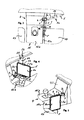
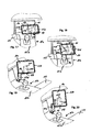
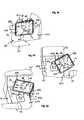
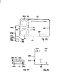
- Fig. 1 shows a perspective view of a first inventive embodiment of the device from the rear with the holder in the horizontal position.
- Fig. 2 shows a perspective view of the device as shown in Fig. 1 with a tablet computer inserted into the holder from the front.
- Fig. 3 shows the device according to illustrations in Fig. 1 and 2, attached to a center console of a vehicle in the non-use position with the holder on the second pivot vertically upwardly pivoted in the horizontal position and in a directed against the passenger seat use position (dashed) from above ,
- FIG. 4 shows a perspective view of the device in the two positions as shown in FIG. 3.
- Fig. 5 shows a perspective view of the device in the non-use position according to illustrations in Figs. 3 and 4 with the holder on the second pivot pivoted vertically downwards in the portrait position.
- Fig. 6 shows a perspective view of the device according to illustrations in Fig. 1 and Fig. 2 pivoted with the holder on the second pivot in a horizontal position of use.
- FIG. 7 shows a perspective view of the device according to illustrations in FIG. 1 and FIG. 2 with the holder in a horizontal format position oriented toward the driver.
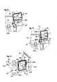
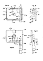
- Fig. 8 shows a partial perspective view of a center console in a vehicle with a on the outside of the directed against the passenger seat side wall of the center console vertically aligned receiving socket.
- FIG. 9 shows a perspective partial view of a center console in a vehicle with a horizontally oriented receiving bush integrated in a cavity of the center console with an insertion opening arranged on the outside of the side wall of the center console directed against the passenger seat.
- FIG. 10 shows a perspective view of the device according to illustrations in FIG. 1 and FIG. 2 with the plug-in element folded over in a compact storage position.
- FIG. 11 shows a perspective partial view of the device with a longitudinally adjustable swivel arm.
- FIG. 12 shows a partial perspective view of the device with a plate-shaped pivot arm and a double joint between the pivot arm and the support element.
- FIG. 13 shows a perspective partial view of the device with a height-adjustable swivel arm on the first pivot.
- Fig. 14 shows a partial perspective view of the device with a manually releasable locking device for holding together the first and second attachment means.
- FIG. 15 shows a perspective view of a second embodiment of the device according to the invention with the holder in the transverse format position from the rear and a vertically aligned receiving socket.
- Fig. 16 shows a perspective view of the device as shown in Fig. 15 with a tablet computer inserted into the holder from the front.
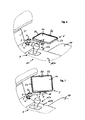
- FIG. 17 shows a first position of use of the device according to illustrations in FIG. 15 and FIG. 16 with the holder in a transverse format position above the center console.
- Fig. 18 shows the position of use of the device as shown in Fig. 17 with the holder in a portrait position.
- FIG. 19 shows a second position of use of the device according to illustrations in FIG. 15 and FIG. 16 with the holder over the leg space of the passenger in a horizontal format position oriented toward the driver.
- Fig. 20 shows the position of use of the device as shown in Fig. 19 with the holder in a portrait position.
- Fig. 21 shows a third position of use of the device according to illustrations in Fig. 15 and Fig. 16 with the holder over the legroom of the passenger in a directed to the passenger transverse format position.
- Fig. 22 shows the position of use of the device as shown in Fig. 21 with the holder in the portrait position.
- Fig. 23 shows the device according to illustrations in Fig. 15 and Fig. 16 in a non-use position with vertically downwardly directed holder in the portrait position next to the directed against the passenger side wall of the center console.
- Fig. 24 shows a view of the device according to illustrations in Fig. 15 and Fig. 16 with the holder in a vertically upward transverse format position from behind.
- FIG. 25 shows a perspective view of the device as shown in Fig. 24 in the folded storage position.
- FIG. 26 shows a perspective partial view of the device according to illustrations in FIGS. 15 to 25 with an adjusting device for vertically aligning the axis of rotation of the first rotary joint.
- FIG. 27 shows a longitudinal section of the partial view of the device as shown in FIG. 26.
- Fig. 28 shows a perspective view of a variant of the connection of the plug element via a pivot joint to the first hinge.
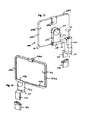
- Fig. 29 shows an exploded view of another embodiment of the first and second fastening means with a locking device.
- FIG. 30 shows a perspective view of the assembled first fastening means and of the second fastening means as shown in FIG. 29 from behind.
- FIG. 30 shows a perspective view of the assembled first fastening means and of the second fastening means as shown in FIG. 29 from behind.
- Fig. 31 shows a cross-sectional view of the first and second fastening means as shown in Fig. 30 in the mated and locked position.
- FIG. 32 shows a longitudinal sectional view of the first fastening means as shown in FIG. 30.
- FIG. 33 shows a partially sectioned side view of a horizontally integrated in a vehicle component receiving socket as shown in Fig. 9 and a pivotable on the first pivot plug element as shown in Fig. 28 which is horizontally inserted into the receiving socket.
- Fig. 34 shows a cross-sectional view of a vertically mounted on the side facing the passenger's side wall of the center console receiving socket as shown in Fig. 8, which is fixed on the top of the center console.
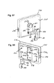
- 35 shows a perspective view of a variant of a vertically oriented receiving bush for screwing on the side wall of a center console directed towards the passenger seat, as shown in FIG. 8.
- Fig. 36 shows a longitudinal sectional view of the receiving socket as shown in Fig. 35, screwed to the side wall of a center console.
- Fig. 37 shows a cross-sectional view of the receiving socket as shown in Fig. 35, screwed to the side wall of a center console.
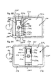
- Fig. 38 shows a perspective view of a variant of the device according to illustrations in Figs. 15 and 16 with stops for limiting the pivoting and pivoting movements of the first and second pivot joints in a non-use position with vertically downwardly directed holder in the horizontal position.
- Fig. 39 shows a perspective view of the device as shown in Fig. 38 in a directed against the passenger transverse format position.
- Fig. 40 shows a perspective view of the device as shown in Fig. 38 in a directed against the driver landscape position.
- Fig. 41 shows a view of the device as shown in Fig. 38 from above.
- Fig. 42 shows a perspective view of the device according to FIG. 38 without a receiving socket from the rear.
- Fig. 43 shows a partially sectioned side view of the device as shown in Fig. 41 from the rear.
- FIG. 44 shows a perspective view of a third embodiment of the device according to the invention with the holder pointing vertically downwards in the transverse format position from behind.
- FIG. 45 shows a side view of the device as shown in FIG. 44.
- Fig. 46 shows a perspective view of the device as shown in Fig. 44 with vertically upwardly directed holder in the horizontal format position from behind.
- FIG. 47 shows a side view of the device as shown in FIG. 46.
- FIG. 47 shows a side view of the device as shown in FIG. 46.
- Fig. 48 shows a front view of the device as shown in Fig. 42 with the holder in a vertically downward position with inserted tablet computer.
- FIG. 49 shows a side view of the device as shown in FIG. 48.
- Fig. 50 shows the front view of the device as shown in Fig. 48 with the holder in a vertically upward position
- FIG. 51 shows a side view of the device as shown in FIG. 50.
- FIG. 51 shows a side view of the device as shown in FIG. 50.
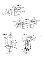
- FIG. 52 shows an exploded view of an alternative fastening device arranged on a guide rail of a vehicle seat.
- FIG. 53 shows a perspective view of the fastening device according to the illustration in FIG. 52 in the assembled state with the plug-in element above the receiving bushing.
- FIG. 54 shows a perspective view of a variant of the fastening device as shown in FIG. 52 and FIG. 53 from the front.
- FIG. 55 shows a perspective view of the fastening device as shown in FIG. 54 from behind.
- FIG. 56 shows a perspective view of a partial view of the fastening device as shown in FIG. 55
- FIG. 57 shows a perspective view of a partial view of the fastening device as shown in FIG. 55.
- FIG. 58 shows an exploded view of the fastening device according to illustrations in FIGS. 54 to 57.
- Fig. 59 shows a partially sectioned side view of an embodiment of the device with a plate-shaped carrier in a horizontally oriented position of use.
- Fig. 60 shows the device as shown in Fig. 59 from above.
- FIG. 61 shows a side view of the device according to illustrations in FIGS. 59 and 60 with the carrier in the vertically oriented non-use position.
- Fig. 62 is a longitudinal sectional view of a carrier cup arranged in the non-use position.
- Fig. 63 shows a longitudinal sectional view of the cup holder as shown in Fig. 62 in the unfolded position of use.
- Fig. 64 shows a partially sectioned side view of the device as shown in Fig. 59 with a container inserted into the carrier and fastened with retaining clips on the carrier.
- Fig. 65 shows the device as shown in Fig. 64 from above.
- FIG. 66 shows the device installed in a vehicle according to illustrations in FIGS. 59 to 63 in the non-use position in a view from above.
- Fig. 67 shows the device as shown in Fig. 66 in two positions of use in a view from above.
- FIG. 68 shows a side view of a variant of the device according to illustrations in FIGS. 59 to 67 with an asymmetrical arrangement of the swivel arm near a longitudinal edge of the carrier with the carrier in the vertically oriented disuse position as shown in FIG. 61
- FIG. 69 shows a variant of the fastening device according to illustrations in FIGS. 52 to 58.
- Fig. 70 shows a perspective view of the arranged at the upper end of the support receiving socket as shown in Fig. 69 with a hinged lid for closing the insertion of the receiving socket in the closed position.
- Fig. 71 shows a cross-sectional view of the receiving socket as shown in Fig. 70 with the hinged lid in the open and the closed position.
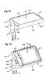
- FIG 72 shows a perspective view of a further embodiment of the device with a plate-shaped carrier which can be rotated about the second rotary joint and can be used on both sides in a horizontal position of use directed against the front passenger.
- FIG. 73 shows a perspective view of the carrier as shown in FIG. 72 with a tablet computer in an oblique position of use.
- Fig. 74 shows a perspective view of the carrier as shown in Fig. 72, rotated 180 ° in a horizontal position of use.
- Fig. 75 shows a perspective view of the carrier as shown in Fig. 74 with a container inserted into the cup-shaped recess of the carrier with a closed lid.
- FIG. 76 shows a perspective view of the carrier as shown in FIG. 75 with one of the two cup holders with the cover open.
- Fig. 77 shows a perspective view of the carrier as shown in Fig. 76 with unfolded support ring of the cup holder and inserted into the support ring cup and unfolded lid of the container.
- FIG. 78 shows a perspective view of a further embodiment of the device with a holder for a mobile telephone arranged on one side of the carrier and a cup-shaped recess in an oblique position of use.
- FIG. 79 shows a perspective view of the carrier rotated by 180 ° as shown in FIG. 78 with a holder for a tablet computer arranged on the rear side.
- Fig. 80 shows a view of the carrier as shown in Fig. 78 from above with the holder without inserted mobile phone.
- Fig. 81 shows a view of the carrier as shown in Fig. 79 from above with the holder without inserted tablet computer.
- Fig. 82 shows an exploded view of the carrier plate with the parts of the holder assembly for the taplet computer.
- Fig. 83 shows a perspective view of the carrier plate with the holder for the tablet computer as shown in Fig. 82, in the assembled state.
- Fig. 84 shows a perspective view of the support plate with the holder for the tablet computer as shown in Fig. 83 with attached housing shells and the slider of the holder in the maximum position.
- Fig. 85 shows a perspective view of the carrier as shown in Fig. 84 with the slider of the holder for the tablet computer in the minimum position.
- Fig. 86 shows a perspective view of the carrier with an exploded view of the pivot arm, pivot post and male member, and the first and second pivot joints.
- FIG. 87 shows a perspective view of a further embodiment of the device with a combination of the housing shell shown in FIGS. 79, 81, 82, 83 and 85 with a holder for differently sized tablet computers, covered with a flat rear wall provided with a hinge and arranged on a transfer arrangement as shown in Fig. 15 from the rear.
- Fig. 88 shows a perspective view of the embodiment as shown in Fig. 87 from the front.
- Figs. 1 to 7 and Fig. 10 show a first embodiment of the device.
- the pivot arm 6 is tubular and aligned horizontally.
- the first pivot 7 is arranged whose axis of rotation z1 is aligned vertically.
- the plug-in element 3 On the underside of the rotary joint 7, the plug-in element 3 is arranged which can be inserted vertically into the insertion opening 2a of a receiving bush 2 arranged in a vehicle component 15.
- the receiving socket 2 is integrated in a cavity of the center console 15 and the insertion opening 2a is aligned approximately with the upper side 15b of the center console 15 (FIGS. 3 to 7).
- a release button 7c is mounted with a positive locking device for the pivot arm 6 can be solved on the pivot 7.
- the second pivot 8 is arranged, which is designed as a tubular extension of the pivot arm and the axis of rotation x1 runs parallel to the longitudinal axis of the pivot arm 6.
- a plate-shaped support arm 10 is disposed on the second pivot 8.
- the longitudinal axes of pivot arm 6 and support arm 10 are perpendicular to each other.
- the holder 5 for a tablet computer 1 is connected to the support arm 10 via the third pivot 11.
- the axis of rotation y of the third rotary joint is perpendicular to the rear wall 5a of the holder 5 and is arranged at the intersection of the diagonal of the rear wall 5a so that the holder 5 is rotatable 360 ° between latched portrait and landscape positions.
- the holder 5 with the first rotary joint 7 can be rotated about a vertical axis Z1 from a storage position (FIGS. 3 and 5) into various positions of use for the driver or front passenger (FIGS. 3, 4, 7). and with the second rotary joint 8 about a horizontal axis X1 pivot (Fig. 5, Fig. 6, Fig. 7) and rotate with the third pivot bearing 11 between portrait and landscape format (Fig. 5).
- a circumferential border 5b is provided, which laterally support the tablet computer 1 inserted in the holder 5 and cover the edges of the screen 1a
- the tablet computer 1 is inserted into the holder 5 from the front (FIG. 2).
- the lower edge of the tablet computer 1 is inserted into the two receiving pockets 5c and the tablet computer 1 is pivoted into the holder 5 until the spring-loaded retaining clip 5d engages over the upper edge of the tablet computer 1.
- FIGS. 8 and 9 show two variants of receiving bushes 2 which are arranged on the side wall 15a of the center console 15 directed against the passenger seat 14.
- Fig. 8 shows a bolted to the side wall 15 a of the center console 15
- Fig. 9 shows an integrated in a cavity of the center console 15 receiving socket 2 whose insertion opening 2a is disposed on the side wall 15a of the center console 15, so that the plug-in element 3 can be inserted horizontally.
- the holder 5 and the plug-in element 3 can be rotated relative to each other about the second rotary joint 8 until the holder 5 and the plug-in element 3 are above or next to each other (FIG. 10).
- FIGS. 11 to 13 show variants of the transfer arrangement.
- FIG. 11 shows a length-adjustable swivel arm 6.
- two tube sections 6 'and 6 are telescopically guided into one another and can be fixed in the desired extension length (not shown).
- Fig. 12 shows a plate-shaped pivot arm 6 on which instead of the second pivot joint 8, a double joint 12 is provided, via which the support arm 10 is connected to the pivot arm 6.
- the double joint 12 comprises the pivot bearing 12 a which is connected to the pivot arm 6 and the pivot bearing 12 b which is connected to the support arm 10.
- the rotary bearing 12a rotates about the rotation axis z2 which runs parallel to the rotation axis z1 of the first rotary joint 7 vertically and the pivot bearing 12b rotates about the rotation axis x2 which runs perpendicular to the rotation axis z2 of the rotary bearing 12a.
- Fig. 13 shows a height-adjustable support member 7d.
- a vertically aligned bearing pin 7a is arranged which forms the rotary joint 7 with a position sleeve 7b arranged at the end 6a of the pivoting arm 6.
- the bearing sleeve 7b can be fixed by friction or a releasable locking device (not shown) in the desired position on the bearing pin 7a.
- Fig. 14 shows a locking device 9a, 9b, 9c, with the plug-in element 3 can be releasably locked in the receiving socket 2.
- a spring tongue 9c is provided on the plug element 3 which is provided with a latching hook 9a which snaps into a mounted on the side wall of the receiving socket 2 recess 9b when the plug element is fully inserted into the receiving socket.
- the spring tongue 9c can be pressed so far in the direction against the first rotary joint 7 until the latching hook 9a releases and the plug-in element 3 can be pulled out of the receiving socket 2.
- the insertion opening 2a of the receiving socket 2 is closed with a hinged lid 2b, so that the receiving socket 2 can not pollute.
- the hinged lid 2 b is pivoted into a cavity to the side so that the plug-in element can be inserted into the receiving socket 2.
- FIGS. 15 to 25 show a second embodiment of the device.
- a vertically upwardly extending support member 17d provided at the upper end of the pivot arm 16 is arranged at right angles to the second pivot 18.
- the second pivot 18 of the support arm 110 is arranged at the upper end of the holder 150 is rotatably mounted to the third pivot 111.
- Plug element 130 approximately parallel to the side edges 150b 'and 150b' 'aligned within the outer contours of the holder 150 (Fig. 25).
- the height of the support element 17d is dimensioned so that the plane of rotation of the pivot arm 16 is so high that the holder 150 can be pivoted to the driver both over the legs of a passenger (FIG. 21) and via the shift knob 15c (FIG.
- FIGS. 17 to 20 Various positions of use of the holder 150 for use by the driver and in FIGS. 21 and 22 for use by the passenger are shown in FIGS. 17 to 20.
- Figs. 17, 19 and 21 show the holder 150 in landscape format.
- FIGS. 18, 20 and 22 show the holder 150 in portrait format.
- Fig. 23 shows the holder 150 in a parallel to the side wall 15a of the center console 15 aligned non-use position in portrait format.
- FIGS. 17 to 23 the respective positions of the first pivot 17, the support member 17d, the pivot arm 16, the second pivot 18, the support arm 110, and the third pivot 111 are shown in dashed lines.
- the positions of the holder 150 shown in FIGS. 17 to 23 are chosen arbitrarily and intermediate positions are dependent on the rotational steps of a detent device. When using friction hinges, any intermediate positions are possible.
- FIGS. 26 and 27 show an adjusting device for vertically aligning the axis of rotation z1 of the first rotary joint 17.
- the contours of the side walls 15a of center consoles 15 to which the receiving bushing 120 is attached (FIG. 8) often do not run vertically.
- a subsequently mounted receiving socket 2, 120 is often mounted obliquely without the aid of a spirit level, so that the plane of rotation of the pivot arm 6, 16 is not horizontal.
- a pivot bearing 17e is arranged which is connected via the pivot bearing 17e '' with the support member 17d and forms the first pivot 7,17.
- a ball-headed hood 130a is attached which, together with the ball socket 17e 'arranged on the lower side of the pivot bearing 17e, forms the ball joint 130a, 17e'.
- a spacer sleeve 17h is arranged which is supported on the pivot bearing 17e and is provided at both ends with internal threads.
- a pressure cap 17f is provided, which is screwed with the clamping screw 17g in the lower thread of the spacer sleeve 17h and the ball head hood 130a biased against the ball socket 17e 'on the pivot bearing 17e.
- the support member 17d By loosening the clamping screw 17g, the support member 17d can be vertically aligned and fixed by tightening the clamping screw 17g in this position.
- the support member 17 d is secured against axial displacement with the collar screw 17 i, which is screwed into the upper thread of the spacer sleeve 17 h, but remains rotatable together with the pivot arm 16.
- FIG. 28 shows a simplified variant of an adjusting device for vertically aligning the axis of rotation z1 of the first rotary joint 17 in one axis.
- the rotary joint 17 is arranged, which is connected via the pivot joint 130 b with the plug element 130.
- the support element 17d can be aligned about an axis and fixed by tightening the locking screw 130b.
- the plug-in element 130 can be folded over and applied to the support element 17d.
- FIGS. 29 to 31 show a further embodiment of the first and second fastening means 120, 130 with a locking device 19a, 19a ', 19a ", 19b.
- the first attachment means 120 comprises a base plate 120b, which is subdivided into the lamellae A to F by means of parallel V-shaped dilution channels (FIGS. 30 and 31).
- the dilution channels have the function of film hinges, so that the base plate 120b can also be fixed on curved surfaces, such as a side wall 15a of a center console 15 ( Figure 8) by gluing or screwing. For screwing on the outer blades A and F screw holes 120 b '' 'are provided.
- each two domes 120b '' are provided at which the intermediate plate 120c, which includes the receiving socket 120, on the mounting arms 120c 'with the screws 120c' 'is attached.
- the intermediate plate 120c and the locking device 19a, 19a ', 19a' ' is arranged. It comprises the L-shaped latching hooks 19a with the release button 19a 'rotatably mounted with the pivot axis 19a' in a arranged on the strip side of the receiving sleeve 120 projection and biased with a (not shown) spring so that the latching hook 19a in the Recess 19b snaps on the plug element 130e and the plug element 130 is locked in the receiving socket 120 (Fig. 31).
- the release button 19a ' By depressing the release button 19a ', the lock is released and the plug 130 can be pulled out of the receiving socket 120.
- a cover hood 120d is provided for covering the intermediate plate 120c.
- Fig. 33 shows a support member 17d at the lower end of the first pivot bearing 17 is arranged.
- the plug element 130 is connected via the pivot joint 130b with the first pivot bearing 17 and can be fixed with the locking screw 130c in the desired positions. Shown is a horizontal position in which the plug element is inserted into a horizontally oriented receiving socket 2, the insertion opening 2a is arranged on the outer wall 15a of a center console 15 (Fig. 9).
- Fig. 34 shows a further variant of a receiving socket 2, which is arranged on the side wall 15 a of a center console 15 and fastened with the fastening arm 2 e and the fastening screw 2 d on the upper side 15 b of the center console 15.
- FIGS. 35 to 37 show a further variant of a receiving bush 2 which is vertically aligned on the side wall 15a of a center console 15 and has an insertion opening 2a arranged at the top.
- a receiving bush 2 which is vertically aligned on the side wall 15a of a center console 15 and has an insertion opening 2a arranged at the top.
- lateral attachment arms 2e ', 2e' 'mounted which are provided with slots 2f', 2f '' for the blind rivet screws 2c, with which the receiving socket 2 with blind rivet nuts 2h is attached to the side wall 15a (Fig 37).
- a recess 2g is provided at the directed against the side wall 15a broad side of the receiving socket 2, so that the receiving socket 2 can be screwed free of tension on arched side walls 15a, including the slots 2f ', 2f' 'are provided in which the screws 2c easily can tilt.
- FIGS. 38 to 43 show a variant of the device which differs from the embodiment shown in FIGS. 15 and 16 in that a stop cam 17 l arranged on the first pivot joint 17 l and a stop slot 17 k arranged horizontally on the outer wall of the support element 17 d the stop cam 17l rotates form stops which limit the angle of rotation of the support member 17d and thus of the pivot arm 16, the support arm 110 and the holder 150 to about 120 ° to 135 °, so that the holder 150 from the non-use position only in a clockwise direction Center console 15 can be rotated in about 120 ° to 135 ° (Fig. 42)
- a stop cam 18a is provided on the second pivot 18 and a stop recess 16c on the pivot arm 16 which limits the pivoting angle of the second pivot 18 and thus of the support arm 110 and the holder 150 to approximately 90 °, so that the holder 150 consists of a vertical downwards non-use position can be pivoted about 90 ° in a horizontal position of use (Fig. 42).
- the tablet computer 1 can be moved from the vertically downward non-use position (FIG. 38) into oblique positions of use for both the front passenger (FIG. 39) and the driver (FIG. Fig. 40) can be aligned without the holder 150 so far in the passenger compartment to pivot that could occur in certain vehicles disabilities in the deployment of the passenger airbag.
- the holder 150 moves in this embodiment between the non-use position and the use positions for driver and front passenger substantially above the center console 15 so that no obstructions of the passenger take place.
- this arrangement allows a very simple and quick adjustment of the holder 150th
- FIGS. 44 to 47 show a further particularly compact and stable embodiment of the device.
- the pivot arm 160 is disposed at the upper end of the support member 170d and the second pivot bearing 180 fork-mounted on the pivot arm 160 wherein the support member 170d and the support arm 110a are approximately aligned.
- the rotation of the holder 150 about the first pivot 170 is carried out on a circular arc with a smaller radius which can be advantageous in tight space conditions in the vehicle.
- Figures 44 and 45 show the device with vertically downwardly directed holder 150
- Figures 46 and 47 show the device with vertically upwardly directed holder 150th
- FIGS. 48 to 51 show the device according to illustrations in FIGS. 38 to 43 with the arrangement of the support element 17d with the first pivot joint 17 and the plug element 130, the pivot arm 16 with the second pivot joint 18 and the support arm 110 with the third pivot bearing 111 with respect to FIG to the longitudinal edges 151a, 151c and the transverse edges 151b, 151d of the holder 150, with the holder in a vertically downwardly directed position ( Figures 48 and 49) and a vertically upwardly directed position ( Figures 50 and 51).
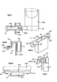
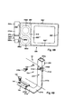
- FIGS. 52 and 53 show an alternative fastening device with which the device can be mounted in a vehicle.
- the fastening device comprises a support 21 which is arranged approximately vertically between the center console and the vehicle seat (not shown) and which is displaceable at the lower end with a fastening element 21a at the front end of a guide rail 14c arranged on the vehicle floor, in which the seat frame 14a of the vehicle seat can be displaced by a carriage 14b is stored, is releasably secured with a screw.
- the support 21 is made of a metal sheet and fastened at the lower end with a screw on the fastening element 21a, which engages under the guide rail 14c U-shaped. At the upper end of the support 21 is bent in a U-shape. On the upper side two tabs are notched out of the sheet which form the counter hooks 21b for the latching hooks 190a of the plug element 30.
- the receiving socket 20 is made of plastic and fastened with a screw connection (not shown) at the upper end of the support 21.
- the support 21 is covered with a Abdeckblende 21c.
- the plug-in element 20 can be inserted from above into the receiving socket 20 until the latching hooks 190a engage in the counter-hook 21b. The locking is released by pressing the release buttons 190a 'on the plug-in element 30th
- FIGS. 54 to 58 show a further variant of the fastening device.
- the support 21 comprises a profile rail 21d with a C-shaped cross-section and transversely arched broadside, so that a high stability of the support is achieved and damage to the upholstery of the vehicle seat when moving the seat is prevented.
- the rail is open at both ends, so that at the upper end of the locking plate 21g can be inserted with the two notched counter hook 21b in the rail and pressed into the rail.
- the fastening element 21a is formed as a C-shaped sheet metal part and encloses the guide rail 14c from below. For mounting, the fastener 21a can be pushed from the front onto the free-standing end of the guide rail 14c.
- the foot 21a "protrudes beyond the platform of the fastener 21a and presses on the top of the guide rail 14c so that when the tightening screws 21f are tightened, the fastener 21a is clamped to the guide rail 14.
- the guide rail 21a ' projects vertically upward and can be inserted into the lower opening of the rail 21d.
- the rail 21d ' is guided linearly displaceable on the guide rail 21a, so that the desired height of the receiving socket can be adjusted and fixed with the locking screw 21e.
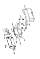
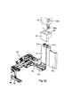
- Fig. 59 to 68 show a further embodiment of the device with a plate-shaped rectangular support 300.
- the basic structure of the support member 270d with the arranged at the bottom of the first pivot 270 and the plug element 230 with the two latching hooks 290a and the two release buttons 290a 'and the am arranged at the top end of swing arm 260 correspond to the previous described concepts to which reference is made.
- the axes of rotation of the first pivot 270 and the second pivot 280 are perpendicular to each other.
- a carrier 300 is arranged, wherein the axis of rotation of the second pivot joint 280 is parallel to the longitudinal edges 300 ', 300' '' of the carrier 300 and centrally between them.
- a receiving space 310 is provided in which the pivoting arm 260 is arranged centrally.
- the second pivot 280 may be disposed between the pivot arm 260 and the support member 270d or between the pivot arm 260 and the support 300 or within a two-part pivot arm 260.
- the carrier 300 is rotatable about the second pivot 280 by 360 °, wherein a (not shown) locking device is provided, with which the carrier 300 in the vertical non-use positions (Fig. 61) and in the horizontal position of use (Figs. 59 and 60) is blocked.
- a release button 300 e is provided to release the lock.
- the cup holders include a cover 300c hingedly connected to the carrier 300 via a first hinge 310c 'and a support ring 300d connected to the cover 300c by a second hinge 300d' 90 °, the axes of rotation of the first hinge 310c 'and of the second rotary joint 300d 'are aligned in parallel.
- the covers 300c and the support rings 300d lie folded over one another parallel to the broad side of the carrier 300 in the cavities of the receiving space 310 (FIG. 62).
- the covers 300c are perpendicular to the broad side of the carrier 300 upwards and the support rings 300d are parallel to the broad side of the carrier 300 and spaced from this aligned (Fig. 63).
- the carrier is cup-shaped and provided with a peripheral outwardly inclined edge 300 ', 300' ', 300' '', 300 '' '' whose upper edges are aligned with the closed covers 300c (Fig. 59 ).
- the outer contour of the receiving tray 400a is complementary to the cup-shaped inner shape of the carrier 300, 300 ', 300' ', 300' '', 300 '' '' designed so that the container 400 is laterally supported when it with the retaining clips 300f ', 300f '' is attached to the carrier 300.
- the lid 400b may be releasably locked to the receiving tray 400a with a locking clip 400c.
- Centrally located recesses 400b ', 400b are provided on the narrow sides of the lid 400b, so that the holding clamps 300f', 300f" hold only the receiving tray 400a to the carrier 300, but the lid 400b of the container 400 is opened and opened via the closing clamp 400c can be locked separately with the receiving tray 400a.
- the retaining clips 300f ', 300f can be moved outwardly until the container 400 can be removed from the carrier 300.
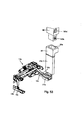
- FIG. 66 shows the device in the inoperative position fastened with the fastening element 21a at the front end of the guide rail 14c for the front passenger seat 14 arranged near the center console 15, as shown and described in FIGS. 52 to 58.
- the carrier 300 can be rotated about the second pivot 280 by 90 ° to a horizontal position of use and pivoted about the first pivot 270 180 ° against the driver's seat 13 or the passenger seat 14.
- Fig. 67 shows two positions of use of the carrier 300 over the center console 15 for use by the driver and over the passenger seat 14 for use by the passenger.
- the carrier 300 When not in use, the carrier 300 can be separated by releasing the latching hooks 290a with the release buttons 290a 'from the receiving socket 20 (FIG. 53) and the support element 270d can be aligned and locked parallel to the broad sides of the carrier 300 for space-saving storage at the second hinge 280 (FIG 61).
- FIG. 68 shows an alternative arrangement of the swivel arm 260 on the carrier 300.
- the swivel arm 260 is arranged near the outer edge 300 'in the receiving space 310.
- the embodiment corresponds to the illustrations in FIGS. 59 to 67 and is provided with identical reference numerals.
- Fig. 69 shows a further variant of the fastening device.
- the support 210 is made in one piece from a stamped / bent part made of sturdy sheet metal and comprises an L-shaped fastening element with the sections 210a, 210b and a support section 210c bent approximately at right angles to the end of the section 210b, the broad sides of the sections 210a , 210b extend approximately parallel to the vehicle floor and the broad side of the support portion 210c approximately parallel to the side wall 15a of the center console 15.
- the upwardly open receiving sleeve 200 is attached.
- the free end of the portion 210a is inserted from the front into the C-shaped guide rail 14c of the passenger seat 14 so far that the screw hole 210a 'disposed on the portion 210a and the screw hole 14c' disposed on the guide rail 14c are congruently superimposed.
- the support 210 and the guide rail 14c are then screwed together with the already existing for mounting the guide rail 14c on the vehicle side screw 14d together on the vehicle floor without additional components are required.
- the support portion 210c is biased with slight bias against the side wall 15a of the center console 15 and abuts with the upper end rubber pad 210d on the side wall 15a of the center console 15 so that vibrations of the support 210 and attached to her devices 1, 300 are prevented.
- a screw 210e is provided with which the support portion 210c at the height of the rubber pad 210d can be screwed to the side wall 15a of the center console 15.
- corresponding holes 210c ', 210d', 15a ' are provided on the support section 210c and on the rubber pad 210d and on the side wall 15a, which lie congruently one over the other when the support 210 has been inserted into the guide rail 14c and fastened with the screw 14d.
- FIGS. 70 and 71 show a hinged lid 200b for closing the insertion opening 20a, 200a of the receiving bush 20, 200 in the closed position.
- the hinged lid 200b is preferably articulated on the directed against the passenger seat 14 wide side wall 200c of the receiving sleeve 200 with a hinge 200b 'with horizontally oriented axis of rotation and biased with the leg spring 200b' 'in the closed position in which it covers the receiving sleeve 200.
- the hinged lid 200b is preferably provided on its outside with large safety radii all around.
- the hinged lid 200b with the leg spring 200b "is pressed against the broad side of the plug element 30, 230, wherein the release buttons 190a ', 290a' for releasing the latch 190a, 290a (FIG ) remain freely accessible.
- the spring-loaded hinged lid 200b automatically closes the plug-in opening 20a, 200a of the receiving socket 20, 200, so that it is protected from contamination.
- FIGS. 72 to 77 show a further embodiment of the device with a support 300 which is rotatable about the second rotary joint 360 360 ° and can be used on both sides.
- one broad side of the carrier (marked A) is designed as a tabletop and the other broad side of the carrier (marked B) is provided with two cup-holders and a tray.
- side B corresponds in principle to the description of the illustrations in FIGS. 59 to 67, to which reference is made. For this reason, the corresponding reference numerals of FIGS. 59 to 67 are also used.
- cups 300a ' are inserted in the support rings 300d of the cup holders and a common finger recess 300c' for detecting the covers 300c.
- brackets 300f 'and 300f shown in FIGS. 64 and 65 for holding the receiving tray 400a of the container 400 to the carrier 300
- retaining lugs 311f', 311f" on the carrier 300 are shown in FIGS. 74, 78 and 79 mounted in the correspondingly arranged retaining lugs (not shown) snap on the receiving tray 400a.
- FIGS. 72 to 77 corresponds in principle to the description of the illustrations in FIGS. 54 to 58 to which reference is made. For this reason, the corresponding reference numerals of FIGS. 54 to 58 are also used.
- the side A of the carrier 300 comprises a flat table top 311 which is provided with a non-slip coating and a peripheral edge 311 ', 311 ", 311"', 311 "'which prevents articles such as e.g. Tablet computer 1 or mobile phones 1 'with inclined support 300 or lateral accelerations of the table top 311 may fall.
- the carrier 300 can be continuously rotated about the first pivot 270 in a horizontal plane and steplessly tilted about the second pivot 280 so that, for example, the screen 1a of a tablet computer 1 or mobile phone 1 'mounted on the carrier 300 is steplessly aligned with the user can.
- the carrier 300 can be rotated by 360 ° at the second rotary joint 280 (FIGS. 59 to 65) and can be locked in the two horizontal positions of use and the two vertical non-use positions of the carrier 300 with a latching device (for example a spring-loaded spur toothing).
- the lock can be unlocked with the release button 300e.
- a friction brake is provided, which fixes the carrier 300 in the intermediate positions by friction.
- Fig. 78 to Fig. 86 show a further embodiment of the device with a on the front side 511a centrally on the pivot arm 560 disposed about the second pivot 580 360 ° rotatably mounted carrier 500 on a broad side (C) a first receiving cup 521 with a centrally in the first receiving tray 521 arranged holder 540 for a mobile phone 1 'and one adjacent to the first receiving tray 521 tray 522 and on the other broadside (D) a second receiving tray 531 with a centrally arranged in the second receiving tray 531 bracket 550 for a tablet computer 1 includes.
- the carrier 500 comprises a carrier plate 510 having a bottom wall 510a with two parallel to the narrow side of the carrier 500 aligned slide guides 512a, 512b for the two slides 541, 551 of the two brackets 540, 550 and arranged in the middle of the end face 511a bearing bushing 511 for receiving the pivot arm 560 and a first housing shell 520 and a second housing shell 530, which are placed on the upper and lower broad side of the support plate 510 and provided with corresponding recesses for the two brackets 540, 550.
- the first housing shell 520 comprises the first receiving tray 521 for receiving the holder 540 for a mobile telephone 1 'and the storage tray 522 and the second housing tray 530 includes the second receiving tray 531 for receiving the holder 550 for a tablet computer 1.
- U-shaped receiving pockets 523, 532 are provided which the edge of the devices (mobile phone 1 'and tablet computer 1) on one side embrace.
- brackets 540, 550 are provided which include a slide 541, 551 with a stop plate (541d, 551d) by moving to different dimensions of the devices 1, 1st 'adapted and can be releasably fixed in the respective positions.
- a retaining clip 545, 555 with a hold-down 545c, 555c is movably arranged and biased by a spring 555d toward the device 1, 1 'and movable so far that the hold-down 545c, 555c the edge of the device 1, 1 'covered.
- the short side walls 521 ", 521" “of the first receiving tray 521 in which the holder 540 for a mobile telephone 1 'is arranged and the short side walls 531", 531 "" of the second receiving tray 531 in which the holder 550 is arranged for a tablet computer (1) form laterally stops for the devices 1, 1 'used in the brackets 540, 550, so that they can not laterally slip out of the brackets 540, 550.
- the holder 540 for a mobile phone 1 'and the holder 550 for a tablet computer 1 are identical in construction using identical parts and will be described in detail below with reference to the illustrations of the holder 550 for a tablet computer 1 in Fig. 82.
- the bracket 550 includes a slider 551 having a bottom plate 551a and a stopper plate 551d arranged at the end of the bottom plate 551a approximately perpendicular to the bottom plate 551a.
- guide rails 551b are mounted which are guided in the slide guides 512b of the bottom wall 510a of the support plate 510a and form with these a linear guide for the slide 551.
- a locking element 553 is arranged which is fastened via a by a detent spring 553b supported spring arm 553a with a screw on the bottom plate 551a.
- a recess 515b for the locking member 553 is provided so that the slider 551 can be moved freely.
- release button 553d mounted with toothed segments 553c arranged on both sides, which are held with the detent spring 553b in engagement with two arranged on the bottom of the bottom wall 510a tooth rails 514 and the slider 551st hold in the desired positions.
- the release button 553d To move the slider 551, the release button 553d must be pressed, causing the toothed segment 553c to disengage from the toothed rails 514.
- the toothed segments 553 c and the toothed rails 514 are provided with saw-toothed teeth which cause the slider 551 can be pushed without actuation of the release button 553 d toward a device inserted into the holder 550 device 1 until the stop plate 551d touches the end wall of the device 1, while a Moving the slider 551 in the opposite direction only after pressing the release button 553d is possible.
- a retaining clip 555 is arranged with a bottom plate 555a which is mounted longitudinally displaceably on the bottom plate 551a of the slider 551.
- a stop wall 555b oriented approximately perpendicular to the bottom plate 555a is arranged with a hold-down 555c oriented approximately parallel to the bottom plate 555a and facing the slider 551.
- a tension spring 555d is arranged which pulls the retaining clip 555 against the slider 551 until the stop wall 555b of the retaining clip 555 abuts the stop plate 551d of the slider 551.
- a recess 555b ' is provided in which the stopper plate 551d of the slider 551 is received.
- the hold-down 555c protrudes beyond the stopper plate 551d and covers the edge of a device 1 inserted in the holder 550 outside the screen 1a, so that the device 1 can not fall out of the holder 550.
- the retaining clip 555 has to be pulled outward against the force of the tension spring 555d until the device 1 is free and can be lifted out of the holder 550.
- a lifting device 552 is attached which the device 1 after opening the retaining clip 555 lifts so far that it can be easily removed from the slide 551.
- the support member 590 and the pivot arm 560 form a common assembly with an L-shaped support member 590a and two symmetrical housing shells 590b. Between the support part 590a and the bearing bush 511 of the carrier 500, a cylindrical connecting piece 610a is inserted, which comprises the second pivot 580 and a friction brake (FIG. 86).
- the plug element 600 comprises a carrier part 600a in which the two locking arms 600c are mounted and a compression spring which presses the locking arms 600c apart and two housing shells 600b. Between the support member 590 and the male member 600, a cylindrical connector 610b is inserted, which includes the first pivot 570 and a friction brake (FIG. 86).
- 87 and 88 show a further embodiment of the device with the second housing shell 530 with a bracket 550, which is arranged in the second receiving shell 531, for differently sized tablet computers 1, combined with a flat rear wall 535 provided with a pivot 535a attached to a transfer arrangement (6, 7, 8, 10, 11, 16, 17, 18, 110, 111, 160, 170, 180, 560, 570, 580, 590) as shown in Fig. 15 and Fig. 16 is directed to the description thereof ,
Landscapes
- Engineering & Computer Science (AREA)
- General Engineering & Computer Science (AREA)
- Mechanical Engineering (AREA)
- Transportation (AREA)
- Vehicle Step Arrangements And Article Storage (AREA)
- Motor Or Generator Frames (AREA)
- Fittings On The Vehicle Exterior For Carrying Loads, And Devices For Holding Or Mounting Articles (AREA)
Abstract
The invention relates to a device for retaining flat, approximately rectangular appliances such as tablet computers (1) or mobile telephones (1') in the interior of a motor vehicle, comprising a fastening apparatus (2, 3, 20, 21, 30, 120, 130, 200, 210, 220, 230, 600) for fastening the device to a vehicle component (4, 15, 14c), a retainer (5, 150, 300, 500, 521, 531, 540, 550) for accommodating the appliances (1, 1'), and a transfer assembly (6, 7, 8, 10, 11, 16, 17, 18, 110, 111, 160, 170, 180, 560, 570, 580, 590), which is provided between the retainer (5, 150, 300, 500, 521, 531, 540, 550) and the fastening apparatus (2, 3, 20, 21, 30, 120, 130, 200, 210, 220, 230, 600) and by means of which the retainer (5, 150, 300, 500, 521, 531, 540, 550) can be moved into different positions in relation to the vehicle component (4, 15, 14c), wherein the transfer assembly (6, 7, 8, 10, 11, 16, 17, 18, 110, 111, 160, 170, 180, 560, 570, 580, 590) comprises a support element (17d, 170d, 270d, 590), which is arranged on the fastening apparatus (2, 3, 20, 21, 30, 120, 130, 200, 210, 220, 230, 600) and which has a first revolute joint (7, 17, 170, 270, 570) having an axis of rotation (z1) oriented approximately vertically, and a pivot arm (6, 16, 160, 260, 560), which is arranged near the upper end of the support element (17d, 170d, 270d, 590) and which has a second revolute joint (8, 18, 180, 280, 580) having an axis of rotation (x1) oriented approximately horizontally, which pivot arm is connected to the retainer (5, 150, 300, 500, 521, 531, 540, 550).
Description
Die Erfindung betrifft eine Vorrichtung zum Halten flacher, in etwa rechteckiger Geräte wie Tablet-Computer oder Mobiltelefone im Innenraum eines Kraftfahrzeugs, insbesondere zur Benutzung durch den Fahrer oder den Beifahrer des Fahrzeugs. Die Erfindung betrifft auch einen Halter für flache in etwa rechteckige Geräte wie Tablet-Computer oder Mobiltelefone, insbesondere einen Halter für eine genannte Vorrichtung. The invention relates to a device for holding flat, approximately rectangular devices such as tablet computers or mobile phones in the interior of a motor vehicle, in particular for use by the driver or the passenger of the vehicle. The invention also relates to a holder for flat approximately rectangular devices such as tablet computers or mobile phones, in particular a holder for a said device.
Die rasche Verbreitung von Tablet-Computern und Mobiltelefonen, insbesondere sogenannten „Smartphones“ führt dazu, dass immer mehr auch die interne Kommunikation von Firmen über Tablet-Computer und Smartphones abgewickelt wird. Dies trifft insbesondere bei der Kommunikation zwischen den Firmenzentralen und den Mitarbeitern im Aussendienst zu.The rapid spread of tablet computers and mobile phones, in particular so-called "smartphones" means that more and more internal company communications are handled by tablet computers and smartphones. This applies in particular to the communication between the company headquarters and the employees in the field service.
Tablet-Computer und Smartphones ermöglichen aber auch den Empfang von zahlreichen Informations- und Unterhaltungsprogrammen, die für den Beifahrer von Interesse sind.But tablet computers and smartphones also allow the reception of numerous information and entertainment programs that are of interest to the passenger.
Für Mitfahrer auf den Rücksitzen sind oft auf der Rückseite von Fahrer- oder Beifahrersitzen angeordnete Halterungen für Tablet-Computer und Smartphones vorgesehen oder nachrüstbar.Rear seat passengers are often provided or retrofitted with tabletop and smartphone mounts on the back of driver or passenger seats.
Verschiedene neue Fahrzeuge sind teilweise mit Halterungen für Smartphones meist in verschliessbaren Ablagefächern unter der Armlehne und Tablet-Computer ähnlichen Bildschirmen am Armaturenbrett ausgestattet die eine interaktive Kommunikation ermöglichen die aber primär fahrzeug- und verkehrsrelevante Informationen für den Fahrer liefern. Various new vehicles are partially equipped with mounts for smartphones usually in lockable storage compartments under the armrest and tablet computer-like screens on the dashboard that allow interactive communication but primarily provide vehicle and traffic information for the driver.
Da für die Vordersitze von Fahrzeugen meist keine Ausklapptische vorgesehen sind, müssen die Tablet-Computer zur Benutzung durch den Fahrer auf den Beifahrersitz oder die Mittelarmlehne gelegt werden. Der Beifahrersitz ist jedoch oft durch eine Person besetzt oder mit anderen Gegenständen versperrt und ein flacher Platz auf der Mittelkonsole meist nur sehr eingeschränkt verfügbar. Für die Arbeiten am Tablet-Computer werden oft auch Akten benötigt was die Handhabung des Tablet-Computers zusätzlich erschwert.Since there are usually no Ausklapptische provided for the front seats of vehicles, the tablet computer must be placed for use by the driver on the front passenger seat or the center armrest. However, the passenger seat is often occupied by one person or locked with other items and a flat space on the center console usually only very limited available. For the work on the tablet computer often also files are needed which complicates the handling of the tablet computer additionally.
Die Benutzung eines Tablet-Computers durch einen Beifahrer ist ohne Behinderung des Fahrers nur möglich, indem der Beifahrer den Tablet-Computer in den Händen hält oder auf die Beine legt, was bei längerer Benutzung sehr unbequem und im Falle eines Unfalles gefährlich sein kann. The use of a tablet computer by a passenger is possible without obstruction of the driver by the passenger holding the tablet computer in his hands or laying on his legs, which can be very uncomfortable for prolonged use and in the event of an accident.
Es sind Ständer und Halter für Tablet-Computer und Smartphones zur Verwendung durch den Fahrer von Fahrzeugen bekannt, doch sind sie oft nur umständlich zugänglich oder behindern oder verunmöglichen die Benutzung des Beifahrersitzes oder die Handhabung von Bedienelementen des Fahrzeugs oder sie verdecken Anzeigen und Lüftungsdüsen oder gefährden die Sicherheit der Fahrzeuginsassen bei Unfällen. There are stands and holders for tablet computers and smartphones for use by the driver of vehicles known, but they are often cumbersome access or obstruct or make impossible the use of the passenger seat or the handling of controls of the vehicle or hide displays and vents or endanger the safety of passengers in the event of accidents.
Eine erste Aufgabe der Erfindung ist es eine Vorrichtung zum Halten flacher, in etwa rechteckiger Geräte wie Tablet-Computer oder Mobiltelefone im Innenraum eines Kraftfahrzeugs zu schaffen die eine bequeme Benutzung dieser Geräte wahlweise durch den Fahrer oder den Beifahrer in unterschiedlichen Gebrauchsstellungen ermöglicht, ohne die Bedienung des Fahrzeugs zu behindern oder einzuschränken oder die Fahrzeuginsassen zu gefährden.A first object of the invention is to provide a device for holding flat, approximately rectangular devices such as tablet computers or mobile phones in the interior of a motor vehicle which allows convenient use of these devices either by the driver or the passenger in different positions of use, without the operation obstruct or restrict the vehicle or endanger the vehicle occupants.
Diese Aufgabe wird durch eine Vorrichtung zum Halten flacher in etwa rechteckiger Geräte wie Tablet-Computer oder Mobiltelefone im Innenraum eines Kraftfahrzeugs mit den Merkmalen des Anspruchs 1 gelöst. This object is achieved by a device for holding flat approximately rectangular devices such as tablet computers or mobile phones in the interior of a motor vehicle having the features of claim 1.
Die Erfindung zeichnet sich folglich durch eine Befestigungseinrichtung zum Befestigen der Vorrichtung an einem Fahrzeugbauteil sowie einen Halter zur Aufnahme der Geräte und eine zwischen dem Halter und der Befestigungseinrichtung vorgesehenen Überführungsanordnung mit der der Halter relativ zum Fahrzeugbauteil in unterschiedliche Stellungen bewegbar ist aus, wobei die Überführungsanordnung ein an der Befestigungseinrichtung angeordnetes Stützelement mit einem ersten Drehgelenk mit einer in etwa vertikal ausgerichteten Drehachse sowie einen nahe dem oberen Ende des Stützelements angeordneten Schwenkarm mit einem zweiten Drehgelenk mit einer in etwa horizontal ausgerichteten Drehachse umfasst, der mit dem Halter verbunden ist.The invention is therefore characterized by a fastening device for fastening the device to a vehicle component and a holder for receiving the devices and provided between the holder and the fastening device transfer arrangement with the holder relative to the vehicle component in different positions is movable, wherein the transfer arrangement a mounted on the fastening means support member having a first pivot having an approximately vertically oriented axis of rotation and a near the upper end of the support member arranged pivot arm with a second pivot having an approximately horizontally oriented axis of rotation, which is connected to the holder.
Die Überführungsanordnung ermöglicht einen sehr einfachen, robusten und kompakten Aufbau der Vorrichtung mit der Möglichkeit den Halter mit dem Tablet-Computer auf kleinsten Raum in jede gewünschte Gebrauchsstellung im Hoch- oder Querformat für eine bequeme Benutzung durch den Fahrer und/oder den Beifahrer oder in eine Nichtgebrauchsstellung in der weder Fahrer noch Beifahrer oder die Bedienung des Fahrzeugs beeinträchtigt werden zu bewegen. The transfer assembly allows a very simple, robust and compact design of the device with the possibility of the holder with the tablet computer in the smallest space in any desired position of use in portrait or landscape format for convenient use by the driver and / or the passenger or in a Non-use position in which neither driver nor passenger nor the operation of the vehicle are affected to move.
Vorteilhafte Ausgestaltungen der Erfindung können sich insbesondere dadurch ergeben,
- dass das Fahrzeugbauteil eine Mittelkonsole die mittig zwischen Fahrer- und Beifahrersitz angeordnet ist umfasst, und wobei das Stützelement nahe einer Seitenwand der Mittelkonsole und nahe der Instrumententafel des Kraftfahrzeugs angeordnet ist und wobei der Halte zwischen einer Aufbewahrungsstellung in der der Halter mit seiner Breitseite in etwa vertikal und parallel zur Seitenwand der Mittelkonsole ausgerichtet vom Stützelement nach hinten weist und unterschiedlichen Gebrauchsstellungen in denen der Bildschirm eines in den Halter eingesetzten Geräts in unterschiedlichen Dreh- und Neigungsstellungen um das erste und zweite Drehgelenk auf den Fahrer und den Beifahrer ausgerichtet ist, bewegbar ist;
- dass der Halter eine in etwa rechteckige Aussenkontur aufweist und wobei die Drehachse des zweiten Drehgelenks in etwa parallel zu den Längsseiten des Halters verläuft;
- dass der Halter an einer Schmalseite vorzugsweise mittig mit dem Schwenkarm verbunden ist;
- dass der Halter nahe einer Längsseite an der Schmalseite mit dem Schwenkarm verbunden ist.
- dass der Schwenkarm an einer Längsseite des Halters angeordnet ist;
- dass der Halter über einen Stützarm mit dem Schwenkarm verbunden ist;
- dass die Längsachse des Schwenkarms und die Längsachse des Stützarms in etwa senkrecht zueinander stehen;
- dass der Halter an seiner Rückwand über ein drittes Drehgelenk dessen Drehachse senkrecht zur Breitseite der Rückwand verläuft mit dem Stützarm verbunden und zwischen einer horizontalen und einer vertikalen Gebrauchslage um mindestens 90° drehbar ist;
- dass die Drehachse des dritten Drehgelenks in etwa im Schnittpunkt der beiden Diagonalen der Rückwand des Halters angeordnet ist;
- dass zwischen dem Schwenkarm und dem Stützarm ein Doppelgelenk angeordnet ist, mit einem Drehlager das mit dem Schwenkarm verbunden ist und einem Schwenklager das mit dem Stützarm verbunden ist und wobei das Drehlager um eine Drehachse dreht, welche parallel zur Drehachse des ersten Drehgelenks verläuft und das Schwenklager um eine Drehachse dreht, welche senkrecht zur Drehachse des Drehlagers verläuft;
- dass das Stützelement und der Schwenkarm ein L-förmiges Bauteil bilden an dessen einem Schenkel das erste Drehgelenk und das zweite Befestigungsmittel und an dessen anderem Schenkel das zweite Drehgelenk und der Halter angeordnet sind;
- dass der Halter in der Nichtgebrauchsstellung neben und/oder über der gegen den Beifahrersitz gerichteten Seitenwand der Mittelkonsole angeordnet ist;
- dass sich der Halter am ersten Drehgelenk aus der Nichtgebrauchsstellung beidseitig um etwa 120° bis 135° drehen lässt;
- dass die Höhe des Stützelements so bemessen ist, dass die Drehebene des Halters so hoch liegt, dass der Halter sowohl über die Beine eines Beifahrers als auch über den Schaltknauf zum Fahrer hin geschwenkt werden kann;
- dass sich der Halter um das zweite Drehgelenk 360° drehen lässt;
- dass das erste Drehgelenk und/oder das zweite Drehgelenk und/oder das dritte Drehgelenk und/oder das Doppelgelenk mit einer Friktionsbremse und/oder einer Rastvorrichtung versehen sind;
- dass Anschläge am ersten Drehgelenk vorgesehen sind, die den Drehwinkel des Schwenkarms in vorbestimmten Positionen begrenzen;
- dass Anschläge am zweiten Drehgelenk vorgesehen sind die den Schwenkwinkel des Halters in vorbestimmten Positionen begrenzen;
- dass die Höhe des Stützelements verstellbar ist;
- dass die Länge des Schwenkarms verstellbar ist;
- dass der Halter eine in etwa rechteckige Aufnahmeschale mit einer Bodenwand und vier umlaufenden Seitenwänden sowie eine an der Bodenwand angeordnete Halterung mit der die Geräte lösbar im Halter festgemacht werden können, umfasst und wobei die Halterungen an unterschiedliche Abmessungen der aufzunehmenden Geräte anpassbar sind;
- dass mehrere Halter an einem Träger angeordnet sind der mit dem Schwenkarm verbunden ist;
- dass der Träger die Form eines flachen Quaders mit zwei in etwa rechteckigen Breitseiten sowie zwei langen und zwei kurzen Seitenwänden aufweist und an einer der kurzen Seitenwänden, vorzugsweise mittig, mit dem Schwenkarm verbunden ist;
- dass der Träger am zweiten Drehlager um 360° drehbar ist und je ein Halter auf je einer der beiden Breitseiten des Trägers angeordnet ist;
- dass eine erste Aufnahmeschale mit einer Halterung für ein Mobiltelefon Teil einer ersten Gehäuseschale und eine zweite Aufnahmeschale mit einer Halterung für einen Tablet-Computer Teil einer zweiten Gehäuseschale bilden und wobei die erste Gehäuseschale und die zweite Gehäuseschale Rücken an Rücken den Träger bilden;
- dass zwischen der ersten Gehäuseschale und der zweiten Gehäuseschale eine Trägerplatte angeordnet ist mit einer Bodenwand mit zwei parallel zur Schmalseite des Trägers ausgerichteten Schieberführungen für Schieber der beiden Halterungen und einer in der Mitte der Stirnseite angeordneten Lagerbuchse zur Aufnahme des Schwenkarms;
- dass die erste Gehäuseschale nebst der ersten Aufnahmeschale mit einer Halterung für ein Mobiltelefon eine an die Aufnahmeschale angrenzende Ablageschale umfasst;
- dass die Befestigungseinrichtung ein am Fahrzeugbauteil angeordnetes erstes Befestigungsmittel und ein mit dem ersten Befestigungsmittel kuppelbares zweites Befestigungsmittel umfasst an dem das Stützelement angeordnet ist;
- dass das erste Befestigungsmittel als Aufnahmebuchse und das zweite Befestigungsmittel als Steckelement ausgebildet sind;
- dass das erste Befestigungsmittel und das zweite Befestigungsmittel mit einer manuell lösbaren Verriegelungsvorrichtung zusammengehalten werden;
- dass das Steckelement am unteren Ende des Stützelements angeordnet ist;
- dass das erste Drehgelenk zwischen dem Steckelement und dem Stützelement angeordnet ist;
- dass die Aufnahmebuchse als Einbauteil in einen Hohlraum der Mittelkonsole integriert oder als Anbauteil an der Aussenseite der Mittelkonsole angeordnet ist;
- dass die Aufnahmebuchse vertikal ausgerichtet in der Mittelkonsole angeordnet ist und wobei die Einstecköffnung für das Steckelement auf der Oberseite der Mittelkonsole, vorzugsweise nahe der gegen den Beifahrersitz gerichteten Seitenwand der Mittelkonsole, angeordnet ist;
- dass die Aufnahmebuchse horizontal ausgerichtet in der Mittelkonsole angeordnet ist und wobei die Einstecköffnung für das Steckelement an der gegen den Beifahrersitz gerichteten Seitenwand der Mittelkonsole angeordnet ist;
- dass die Aufnahmebuchse horizontal oder vertikal ausgerichtet als separates Teil auf der Aussenseite der gegen den Beifahrersitz gerichteten Seitenwand der Mittelkonsole angeordnet ist;
- dass die Einstecköffnung der Aufnahmebuchse mit einem federbeaufschlagten Klappdeckel verschlossen ist, der beim Einstecken des Steckelements verschwenkt wird und die Einstecköffnung freigibt;
- dass das Steckelement über ein Drehgelenk mit dem Stützelement verbunden ist.
- dass die Befestigungseinrichtung eine zwischen der Mittelkonsole und dem Fahrer- oder Beifahrersitz angeordnete Stütze umfasst, die mit einem Befestigungselement am Fahrzeugboden oder an einer der nahe der Mittelkonsole am Fahrzeugboden angeordneten Führungsschienen von Fahrer- oder Beifahrersitzen befestigt ist;
- dass das Befestigungselement die Führungsschiene am vorderen Ende von aussen umgreift;
- dass das Befestigungselement eine in etwa rechtwinklig zur Stütze und parallel zum Fahrzeugboden ausgerichtete L-förmige Platte mit einem ersten Abschnitt und einem zweiten Abschnitt umfasst und wobei der erste Abschnitt von vorne in die Führungsschiene eingeführt und zusammen mit der Führungsschiene am Fahrzeugboden festgeschraubt wird und der zweite Abschnitt den ersten Abschnitt mit dem Stützabschnitt der Stütze verbindet;
- dass das Befestigungselement mit dem Stützabschnitt und der Stütze ein einteiliges Stanz- Biegeteil bilden;
- dass die Stütze nahe ihrem oberen Ende mit einer Schraub- oder Klebverbindung oder mit einer Verhakung an der Mittelkonsole insbesondere an der Seitenwand der Mittelkonsole befestigt wird;
- dass die Stütze längsverschiebbare Segmente und ein Feststellelement umfasst so dass die Höhe der Stütze verstellbar ist;
- dass am oberen Ende der Stütze eine Aufnahmebuchse angeordnet ist mit der ein am Stützelement angeordnetes Steckelement koppelbar ist; und/oder
- dass die Einstecköffnung an der Oberseite der Aufnahmebuchse angeordnet und mit einem gefederten Klappdeckel verschliessbar ist.
- that the vehicle component comprises a center console which is arranged centrally between the driver and front passenger seats, and wherein the support element is arranged near a side wall of the center console and near the instrument panel of the motor vehicle and wherein the holding between a storage position in which the holder with its broad side in approximately vertical and parallel to the side wall of the center console facing away from the support member and movable in different use positions in which the screen of a device inserted in the holder is in different rotational and inclination positions about the first and second pivot on the driver and the passenger;
- that the holder has an approximately rectangular outer contour and wherein the axis of rotation of the second pivot joint is approximately parallel to the longitudinal sides of the holder;
- that the holder is connected to a narrow side, preferably centrally with the pivot arm;
- the holder is connected to the swivel arm near a longitudinal side on the narrow side.
- that the pivot arm is disposed on a longitudinal side of the holder;
- that the holder is connected via a support arm to the pivot arm;
- that the longitudinal axis of the pivot arm and the longitudinal axis of the support arm are approximately perpendicular to each other;
- that the holder is connected at its rear wall via a third pivot whose axis of rotation perpendicular to the broad side of the rear wall connected to the support arm and is rotatable between a horizontal and a vertical position of use by at least 90 °;
- that the axis of rotation of the third rotary joint is arranged approximately at the intersection of the two diagonals of the rear wall of the holder;
- that between the pivot arm and the support arm, a double joint is arranged, with a pivot bearing which is connected to the pivot arm and a pivot bearing which is connected to the support arm and wherein the pivot bearing rotates about an axis of rotation which is parallel to the axis of rotation of the first pivot joint and the pivot bearing rotates about an axis of rotation which is perpendicular to the axis of rotation of the pivot bearing;
- in that the support element and the pivoting arm form an L-shaped component on whose one leg the first pivot joint and the second fastening means and on the other leg of which the second pivot joint and the holder are arranged;
- that the holder is arranged in the non-use position next to and / or above the side wall of the center console directed against the passenger's seat;
- that the holder on the first hinge from the non-use position can be rotated on both sides by about 120 ° to 135 °;
- that the height of the support member is dimensioned so that the plane of rotation of the holder is so high that the holder can be pivoted both over the legs of a passenger and on the shift knob to the driver;
- that the holder can be rotated 360 ° about the second pivot;
- the first rotary joint and / or the second rotary joint and / or the third rotary joint and / or the double joint are provided with a friction brake and / or a latching device;
- that stops are provided on the first pivot, which limit the angle of rotation of the pivot arm in predetermined positions;
- that stops are provided on the second pivot which limit the pivot angle of the holder in predetermined positions;
- that the height of the support element is adjustable;
- that the length of the pivot arm is adjustable;
- that the holder comprises a roughly rectangular receiving tray having a bottom wall and four circumferential side walls and a holder arranged on the bottom wall with which the devices can be releasably secured in the holder, and wherein the holders are adaptable to different dimensions of the devices to be recorded;
- that a plurality of holders are arranged on a carrier which is connected to the pivot arm;
- that the carrier has the shape of a flat cuboid with two approximately rectangular broad sides and two long and two short side walls and is connected to one of the short side walls, preferably centrally, with the pivot arm;
- that the carrier on the second pivot bearing is rotatable by 360 ° and each one holder is arranged on each one of the two broad sides of the carrier;
- that a first receiving tray with a holder for a mobile phone part of a first housing shell and a second receiving tray with a holder for a tablet computer part of a second housing shell and form the first housing shell and the second housing shell back to back the carrier;
- that between the first housing shell and the second housing shell, a support plate is arranged with a bottom wall with two aligned parallel to the narrow side of the carrier slide guides for slide the two brackets and arranged in the middle of the end face bearing bush for receiving the pivot arm;
- that the first housing shell together with the first receiving tray with a holder for a mobile phone comprises a tray adjacent to the receiving tray;
- in that the fastening device comprises a first fastening means arranged on the vehicle component and a second fastening means which can be coupled to the first fastening means and on which the supporting element is arranged;
- that the first fastening means are designed as a receiving socket and the second fastening means as a plug-in element;
- that the first attachment means and the second attachment means are held together with a manually releasable locking device;
- that the plug element is arranged at the lower end of the support element;
- that the first pivot joint between the plug element and the support element is arranged;
- that the receiving socket is integrated as a built-in part in a cavity of the center console or arranged as an attachment on the outside of the center console;
- that the receiving socket is arranged vertically aligned in the center console and wherein the insertion opening for the plug-in element on the upper side of the center console, preferably near the directed against the passenger seat side wall of the center console, is arranged;
- that the receiving socket is arranged horizontally aligned in the center console and wherein the insertion opening for the plug element is arranged on the side wall of the center console directed against the passenger seat;
- that the receiving socket is arranged horizontally or vertically aligned as a separate part on the outside of the directed against the passenger seat side wall of the center console;
- that the insertion opening of the receiving socket is closed by a spring-loaded hinged lid, which is pivoted upon insertion of the plug element and releases the insertion opening;
- that the plug element is connected via a hinge with the support element.
- in that the fastening device comprises a support arranged between the center console and the driver or front-passenger seat, which is fastened with a fastening element on the vehicle floor or on one of the guide rails of driver or front passenger seats arranged near the center console on the vehicle floor;
- that the fastener engages around the guide rail at the front end from the outside;
- that the fastening element comprises an approximately perpendicular to the support and parallel to the vehicle floor aligned L-shaped plate having a first portion and a second portion and wherein the first portion is inserted from the front into the guide rail and bolted together with the guide rail on the vehicle floor and the second Section connects the first section with the support portion of the support;
- that the fastening element with the support portion and the support form a one-piece stamped and bent part;
- that the support is fastened near its upper end with a screwed or glued connection or with a hooking on the center console, in particular on the side wall of the center console;
- that the support includes longitudinally displaceable segments and a locking member so that the height of the support is adjustable;
- that at the upper end of the support a receiving socket is arranged with a arranged on the support element plug element can be coupled; and or
- that the insertion opening is arranged on the upper side of the receiving socket and can be closed with a spring-loaded hinged lid.
Sämtliche der genannten Merkmale können dabei einzeln oder in beliebiger Kombination miteinander erfindungswesentlich sein. All of the features mentioned may be essential to the invention individually or in any combination with one another.
Eine andere Aufgabe der Erfindung ist es, einen Halter für flache in etwa rechteckige Geräte wie Tablet-Computer oder Mobiltelefone zu schaffen der an unterschiedliche Abmessungen der Geräte anpassbar ist und einen optimalen Schutz vor Verletzungen der Passagiere bei Unfällen gewährleistet.Another object of the invention is to provide a holder for flat approximately rectangular devices such as tablet computers or mobile phones which is adaptable to different dimensions of the devices and ensures optimum protection against injury to passengers in accidents.
Diese Aufgabe wird durch einen Halter mit den Merkmalen des Anspruchs 48 gelöst. Vorgesehen wird also ein Halter, insbesondere ein Halter einer oben beschriebenen Vorrichtung, mit einer in etwa rechteckigen Aufnahmeschale mit einer Bodenwand und vier umlaufenden Seitenwänden sowie einer Halterung mit einer auf einer Seite der Aufnahmeschale angeordneten U-förmigen Aufnahmetasche die einen Rand eines in die Halterung eingesetzten Geräts umgreift und einer beweglich gelagerten gefederten Halteklammer mit einem Niederhalter der den gegenüberliegenden Rand eines in die Halterung eingesetzten Geräts überdeckt, wobei
- ein an der Bodenwand der Aufnahmeschale beweglich geführter Schieber vorgesehen ist, mit einer Bodenplatte und einer am Ende der Bodenplatte in etwa senkrecht zur Bodenplatte angeordneten Anschlagplatte,
- der Schieber soweit verstellbar ist bis die Anschlagplatte am gegenüberliegenden Rand des Geräts ansteht und in dieser Position mit einer manuell lösbaren Verriegelungsvorrichtung an der Bodenwand feststellbar ist, und
- die Halteklammer mit dem Niederhalter beweglich am Schieber geführt und mit einer Feder gegen die Anschlagplatte vorgespannt ist wobei der Niederhalter in der Endlage der Halteklammer soweit über die Anschlagplatte hinausragt dass der gegenüberliegenden Rand des Geräts überdeckt wird.
- a slider movably guided on the bottom wall of the receiving tray is provided, with a bottom plate and a stop plate arranged at the end of the bottom plate approximately perpendicular to the bottom plate,
- the slider is adjustable until the stop plate is present at the opposite edge of the device and in this position with a manually releasable locking device on the bottom wall is detected, and
- the retaining clip with the hold-down movably guided on the slide and is biased by a spring against the stop plate wherein the hold-down in the end position of the retaining clip projects beyond the stop plate so far that the opposite edge of the device is covered.
Vorteilhafte Weiterbildungen der Erfindung sind in den abhängigen Ansprüchen beschrieben, wobei sich vorteilhafte Ausgestaltungen insbesondere dadurch ergeben können,
- dass die Aufnahmetasche an einer der langen Seitenwände der Aufnahmeschale ausgebildet ist;
- dass an der Bodenplatte des Schiebers Führungsschienen angeordnet sind die in parallel zu den kurzen Seitenwänden verlaufenden Schieberführungen an der Bodenwand der Aufnahmeschale geführt sind;
- dass die Verriegelungsvorrichtung mindestens eine, vorzugsweise auf der Unterseite, an der Bodenwand der Aufnahmeschale angeordnete Zahnschiene sowie mindestens ein beweglich an der Bodenplatte des Schiebers angeordnetes Zahnsegment das mit einer Rastfeder in Eingriff mit der Zahnschiene gehalten wird umfasst und wobei das Zahnsegment mit einer an der Bodenplatte des Schiebers angeordneten Lösetaste aus der Zahnschiene bewegt und so die Verriegelung gelöst werden kann;
- dass die Zahnschiene und das Zahnsegment mit sägezahnförmigen Verzahnungen versehen sind, so dass der Schieber ohne Betätigung der Lösetaste in Richtung gegen das in die Halterung eingesetzte Gerät geschoben werden kann, während ein Verschieben des Schiebers in die Gegenrichtung erst nach betätigen der Lösetaste möglich ist;
- dass das Zahnsegment und die Lösetaste ein Verriegelungselement bilden das mit der als Blattfeder ausgebildeten Rastfeder an der Unterseite der Bodenplatte des Schiebers befestigt ist und wobei in der Bodenplatte des Schiebers eine Tastenausnehmung vorgesehen ist durch welche die Lösetaste nach oben ragt.
- dass in der Bodenwand der Aufnahmeschale zwischen den Schieberführungen eine längliche Ausnehmung für das Verriegelungselement freigespart ist;
- dass die Halteklammer eine Bodenplatte sowie eine am freien Ende der Bodenplatte in etwa senkrecht zur Bodenplatte ausgerichtete Anschlagwand mit einem in etwa parallel zur Bodenplatte ausgerichteten und gegen den Schieber weisenden Niederhalter umfasst und wobei die Bodenplatte der Halteklammer in der Bodenplatte des Schiebers längsverschiebbar geführt ist;
- dass zwischen dem Schieber und der Halteklammer eine Zugfeder angeordnet ist welche die Halteklammer soweit gegen den Schieber zieht bis die Anschlagwand der Halteklammer an der Anschlagplatte des Schiebers ansteht;
- dass an der Anschlagwand der Halteklammer eine Vertiefung vorgesehen ist, in der die Anschlagplatte des Schiebers in der Endlage der Halteklamme aufgenommen wird;
- dass der Niederhalter in der Endlage der Halteklammer die Anschlagplatte des Schiebers soweit überragt dass der Rand eines in die Halterung eingesetzten Geräts ausserhalb des Bildschirms überdeckt wird so dass das Gerät nicht aus der Halterung fallen kann und wobei zur Entnahme des Geräts aus der Halterung die Halteklammer gegen die Kraft der Zugfeder hinter die Anschlagplatte des Schiebers gezogen werden muss bis das Gerät frei ist und aus der Halterung entnommen werden kann;
- dass auf der Oberseite der Bodenplatte des Schiebers eine Hebevorrichtung angebracht ist welche ein in die Halterung eingesetztes Gerät nach dem Zurückziehen der Halteklammer mit dem Niederhalter soweit anhebt dass es bequem aus dem Schieber entnommen werden kann;
- dass die kurzen Seitenwände der Aufnahmeschalen in der die Halterungen für ein Mobiltelefon oder einen Tablet-Computer angeordnet sind seitliche Anschläge für die in die Halterungen eingesetzten Geräte bilden so dass diese nicht seitlich aus den Halterungen rutschen können;
- dass eine erste Aufnahmeschale mit einer Halterung für ein Mobiltelefon Teil einer ersten Gehäuseschale und eine zweite Aufnahmeschale mit einer Halterung für einen Tablet-Computer Teil einer zweiten Gehäuseschale bilden und wobei die erste Gehäuseschale und die zweite Gehäuseschale Rücken an Rücken einen Träger bilden der mit einer Überführungsanordnung mit einem Fahrzeugbauteil eines Kraftfahrzeuges verbunden werden kann;
- dass eine erste Aufnahmeschale mit einer Halterung für ein Mobiltelefon Teil einer ersten Gehäuseschale oder eine zweite Aufnahmeschale mit einer Halterung für einen Tablet-Computer Teil einer zweiten Gehäuseschale bilden und wobei die erste Gehäuseschale oder die zweite Gehäuseschale mit einer vorzugsweise flachen Rückwand ausgestattet ist und mit einer Überführungsanordnung mit einem Fahrzeugbauteil eines Kraftfahrzeuges verbunden werden kann;
- dass zwischen der Rückwand der zweiten Gehäuseschale und der Überführungsanordnung ein Drehgelenk angeordnet ist mit dem die Gehäuseschale zwischen Hoch- und Querformat drehbar ist;
- dass eine lösbare Kupplung vorgesehen ist mit der die Gehäuseschalen mit dem Fahrzeugbauteil verbunden werden können;
- dass die lösbare Kupplung ein mit den Gehäuseschalen direkt oder indirekt verbundenes Steckelement und eine direkt oder indirekt mit dem Fahrzeugbauteil verbundene Aufnahmebuchse umfasst;
- dass eine erste Aufnahmeschale mit einer Halterung für ein Mobiltelefon Teil einer ersten Gehäuseschale oder eine zweite Aufnahmeschale mit einer Halterung für einen Tablet-Computer Teil einer zweiten Gehäuseschale bilden und wobei die erste Gehäuseschale oder die zweite Gehäuseschale mit einer vorzugsweise flachen und mit einem ersten Kupplungselement verbundenen Rückwand ausgestattet ist und mit einem mit einem zweiten Kupplungselement ausgerüsteten Fahrzeugbauteil eines Kraftfahrzeuges lösbar gekoppelt werden kann;
- dass das erste Kupplungselement ein vorzugsweise einklappbares Steckelement und das zweite Kupplungselement eine Aufnahmebuchse umfassen; und/oder
- dass die vier umlaufenden Seitenwände der Aufnahmeschalen die Oberkanten der in die Halterung eingesetzten Geräte abdecken.
- that the receiving pocket is formed on one of the long side walls of the receiving tray;
- that on the bottom plate of the slide guide rails are arranged which are guided in parallel to the short side walls extending slide guides on the bottom wall of the receiving tray;
- in that the locking device comprises at least one toothed rail, preferably arranged on the underside, on the bottom wall of the receiving tray, and at least one toothed segment movably mounted on the bottom plate of the slide and held with a detent spring in engagement with the toothed rail, and the toothed segment with one on the bottom plate the slide arranged release button moves out of the rack and so the lock can be solved;
- that the toothed rail and the toothed segment are provided with sawtooth-shaped teeth, so that the slide can be pushed without actuation of the release button in the direction against the device inserted into the holder, while a displacement of the slider in the opposite direction is possible only after pressing the release button;
- the toothed segment and the release button form a locking element which is fastened to the underside of the bottom plate of the slider by the latch spring designed as a leaf spring and wherein a key recess is provided in the bottom plate of the slider through which the release button projects upwards.
- that in the bottom wall of the receiving tray between the slider guides an elongated recess for the locking element is freed;
- in that the retaining clip comprises a bottom plate and a stop wall oriented approximately perpendicular to the bottom plate at the free end with a holding-down device oriented approximately parallel to the bottom plate and pointing towards the slide, and wherein the bottom plate of the holding clamp is longitudinally displaceably guided in the bottom plate of the slide;
- that between the slider and the retaining clip, a tension spring is arranged which pulls the retaining clip as far against the slider until the stop wall of the retaining clip is present at the stop plate of the slider;
- that on the stop wall of the retaining clip a recess is provided, in which the stop plate of the slider is received in the end position of the retaining clamp;
- that the hold-down in the end position of the retaining clip projects far beyond the stop plate of the slide so that the edge of a device inserted into the holder is covered outside the screen so that the device can not fall out of the holder and wherein for removing the device from the holder, the retaining clip against The force of the tension spring must be pulled behind the stop plate of the slide until the device is free and can be removed from the holder;
- that on the upper side of the bottom plate of the slider, a lifting device is mounted which raises a device inserted into the holder after retraction of the retaining clip with the hold down so far that it can be easily removed from the slide;
- that the short side walls of the receiving cups in which the holders for a mobile phone or a tablet computer are arranged form lateral stops for the devices inserted into the holders so that they can not slip laterally out of the holders;
- in that a first receiving tray with a holder for a mobile telephone forms part of a first housing shell and a second receiving tray with a holder for a tablet computer forms part of a second housing shell, and wherein the first housing shell and the second housing shell form a carrier back to back with a transfer arrangement can be connected to a vehicle component of a motor vehicle;
- a first receiving tray with a holder for a mobile telephone part of a first housing shell or a second receiving tray with a holder for a tablet computer part of a second housing shell and wherein the first housing shell or the second housing shell is equipped with a preferably flat rear wall and with a Transfer arrangement can be connected to a vehicle component of a motor vehicle;
- that between the rear wall of the second housing shell and the transfer arrangement, a rotary joint is arranged with which the housing shell is rotatable between portrait and landscape format;
- that a releasable coupling is provided with which the housing shells can be connected to the vehicle component;
- that the releasable coupling comprises a plug-in element which is directly or indirectly connected to the housing shells and a receiving bush which is connected directly or indirectly to the vehicle component;
- that a first receiving tray with a holder for a mobile phone part of a first housing shell or a second receiving tray with a holder for a tablet computer part of a second housing shell and wherein the first housing shell or the second housing shell with a preferably flat and connected to a first coupling element Rear wall is equipped and can be releasably coupled with a vehicle equipped with a second coupling element vehicle component of a motor vehicle;
- that the first coupling element comprises a preferably foldable plug-in element and the second coupling element comprise a receiving bushing; and or
- that the four circumferential side walls of the receiving trays cover the upper edges of the devices inserted into the holder.
Sämtliche der genannten Merkmale können dabei einzeln oder in beliebiger Kombination miteinander erfindungswesentlich sein. All of the features mentioned may be essential to the invention individually or in any combination with one another.
Die Überführungsanordnung weist vorzugsweise einen Schwenkarm auf der über ein erstes Drehgelenk mit einer in etwa vertikal ausgerichteten Drehachse mit der Befestigungseinrichtung und über ein zweites Drehgelenk mit einer in etwa horizontal ausgerichteten Drehachse mit dem Halter oder dem Träger verbunden ist.The transfer assembly preferably has a pivot arm on which a first rotary joint with an approximately vertically oriented axis of rotation with the fastening device and a second rotary joint with an approximately horizontally oriented axis of rotation with the holder or the carrier is connected.
Die Überführungsanordnung ermöglicht einen sehr einfachen, robusten und kompakten Aufbau der Vorrichtung mit der Möglichkeit den Halter oder den Träger mit dem Tablet-Computer und/oder dem Mobiltelefon auf kleinstem Raum in jede gewünschte Gebrauchsstellung im Hoch- oder Querformat für eine bequeme Benutzung durch den Fahrer und/oder den Beifahrer oder in eine Nichtgebrauchsstellung in der weder Fahrer noch Beifahrer oder die Bedienung des Fahrzeugs beeinträchtigt werden zu bewegen. The transfer arrangement allows a very simple, robust and compact design of the device with the possibility of the holder or the carrier with the tablet computer and / or the mobile phone in the smallest space in any desired position of use in portrait or landscape format for convenient use by the driver and / or the passenger or in a non-use position in which neither driver nor passenger nor the operation of the vehicle are impaired.
In einer bevorzugten Ausführungsform ist die Vorrichtung so ausgerichtet im Fahrzeug befestigt dass die Drehachse des ersten Drehgelenks in etwa vertikal verläuft und der Schwenkarm sich vorzugsweise in einer in etwa horizontal ausgerichteten Ebene drehen lässt.In a preferred embodiment, the device is mounted in the vehicle so aligned that the axis of rotation of the first pivot extends approximately vertically and the pivot arm preferably rotates in an approximately horizontal plane.
Bevorzugt sind das erste Drehgelenk am unteren Ende des Stützelements zwischen dem Steckelement und dem Stützelement und das zweite Drehgelenk am Ende des Schwenkarms zwischen dem Schwenkarm und dem Halter oder dem Träger angeordnet.
Preferably, the first pivot at the lower end of the support member between the plug member and the support member and the second pivot at the end of the pivot arm between the pivot arm and the holder or the carrier are arranged.
Preferably, the first pivot at the lower end of the support member between the plug member and the support member and the second pivot at the end of the pivot arm between the pivot arm and the holder or the carrier are arranged.
In einer weiteren bevorzugten Ausführungsform weist der Halter eine in etwa rechteckige Aussenkontur auf und die Drehachse des zweiten Drehgelenks verläuft in etwa parallel zu jeweils zwei Aussenkanten des Halters, wobei der Schwenkarm nahe einer Aussenkante des Halters angeordnet und parallel zu dieser ausgerichtet ist.
In a further preferred embodiment, the holder has an approximately rectangular outer contour and the axis of rotation of the second pivot extends approximately parallel to each two outer edges of the holder, wherein the pivot arm is disposed near an outer edge of the holder and aligned parallel thereto.
In a further preferred embodiment, the holder has an approximately rectangular outer contour and the axis of rotation of the second pivot extends approximately parallel to each two outer edges of the holder, wherein the pivot arm is disposed near an outer edge of the holder and aligned parallel thereto.
In einer weiteren bevorzugten Ausführungsform ist der Halter über einen Stützarm mit dem Schwenkarm verbunden wobei die Längsachse des Schwenkarms und die Längsachse des Stützarms in etwa senkrecht zueinander stehen.In a further preferred embodiment, the holder is connected via a support arm to the pivot arm wherein the longitudinal axis of the pivot arm and the longitudinal axis of the support arm are approximately perpendicular to each other.
Bevorzugt sind der Stützarm und das Stützelement parallel zueinander ausgerichtet und an je einem Ende rechtwinklig mit dem Schwenkarm verbunden.
Preferably, the support arm and the support element are aligned parallel to each other and connected at one end at a right angle to the pivot arm.
Preferably, the support arm and the support element are aligned parallel to each other and connected at one end at a right angle to the pivot arm.
Der Halter ist vorzugsweise an seiner Rückwand über ein drittes Drehgelenk dessen Drehachse senkrecht zur Breitseite der Rückwand verläuft mit dem Stützarm verbunden und zwischen einer horizontalen und einer vertikalen Gebrauchslage um mindestens 90° drehbar, wobei die Drehachse des dritten Drehgelenks vorzugsweise in etwa im Schnittpunkt der beiden Diagonalen der Rückwand des Halters angeordnet ist.
The holder is preferably connected at its rear wall via a third pivot whose axis of rotation perpendicular to the broad side of the rear wall connected to the support arm and rotatable between a horizontal and a vertical position of use by at least 90 °, wherein the axis of rotation of the third pivot preferably approximately at the intersection of the two Diagonals of the rear wall of the holder is arranged.
The holder is preferably connected at its rear wall via a third pivot whose axis of rotation perpendicular to the broad side of the rear wall connected to the support arm and rotatable between a horizontal and a vertical position of use by at least 90 °, wherein the axis of rotation of the third pivot preferably approximately at the intersection of the two Diagonals of the rear wall of the holder is arranged.
In einer weiteren Ausführungsform ist vorgesehen dass zwischen dem Schwenkarm und dem Stützarm ein Doppelgelenk angeordnet ist mit einem Drehlager das mit dem Schwenkarm verbunden ist und einem Schwenklager das mit dem Stützarm verbunden ist, wobei das Drehlager um eine Drehachse dreht, welche parallel zur Drehachse des ersten Drehgelenks verläuft und das Schwenklager um eine Drehachse dreht, welche senkrecht zur Drehachse des Drehlagers verläuft.
In a further embodiment it is provided that between the pivot arm and the support arm, a double joint is arranged with a pivot bearing which is connected to the pivot arm and a pivot bearing which is connected to the support arm, wherein the pivot bearing rotates about an axis of rotation which is parallel to the axis of rotation of the first Swivel joint runs and the pivot bearing rotates about an axis of rotation which is perpendicular to the axis of rotation of the pivot bearing.
In a further embodiment it is provided that between the pivot arm and the support arm, a double joint is arranged with a pivot bearing which is connected to the pivot arm and a pivot bearing which is connected to the support arm, wherein the pivot bearing rotates about an axis of rotation which is parallel to the axis of rotation of the first Swivel joint runs and the pivot bearing rotates about an axis of rotation which is perpendicular to the axis of rotation of the pivot bearing.
In einer Weiterbildung können am ersten Drehgelenk und/oder am zweiten Drehgelenk und/oder am dritten Drehgelenk manuell lösbare Anschläge vorgesehen werden die den Drehwinkel des Stützelements oder des Schwenkarms oder des Halters in vorbestimmten Positionen begrenzen.
In a further development, manually releasable stops can be provided on the first pivot joint and / or on the second pivot joint and / or on the third pivot joint which limit the angle of rotation of the support element or of the pivot arm or of the holder in predetermined positions.
In a further development, manually releasable stops can be provided on the first pivot joint and / or on the second pivot joint and / or on the third pivot joint which limit the angle of rotation of the support element or of the pivot arm or of the holder in predetermined positions.
Bevorzugt ist die Aufnahmebuchse als Einbauteil in einen Hohlraum einer Mittelkonsole integriert oder als Anbauteil an der Aussenseite einer Mittelkonsole angeordnet.
Preferably, the receiving socket is integrated as a built-in part in a cavity of a center console or arranged as an attachment to the outside of a center console.
Preferably, the receiving socket is integrated as a built-in part in a cavity of a center console or arranged as an attachment to the outside of a center console.
In einer weiteren bevorzugten Ausführungsform ist die Aufnahmebuchse vertikal ausgerichtet in der Mittelkonsole angeordnet und die Einstecköffnung für das Steckelement auf der Oberseite der Mittelkonsole, vorzugsweise nahe der gegen den Beifahrersitz gerichteten Seitenwand der Mittelkonsole, angeordnet.
In a further preferred embodiment, the receiving socket is arranged vertically aligned in the center console and the insertion opening for the plug element on the upper side of the center console, preferably arranged near the side wall of the center console directed against the passenger seat.
In a further preferred embodiment, the receiving socket is arranged vertically aligned in the center console and the insertion opening for the plug element on the upper side of the center console, preferably arranged near the side wall of the center console directed against the passenger seat.
Alternativ kann die Aufnahmebuchse horizontal ausgerichtet in der Mittelkonsole angeordnet und die Einstecköffnung für das Steckelement an der gegen den Beifahrersitz gerichteten Seitenwand der Mittelkonsole angeordnet sein.
Alternatively, the receiving socket can be arranged horizontally aligned in the center console and the insertion opening for the plug element can be arranged on the directed against the passenger seat side wall of the center console.
Alternatively, the receiving socket can be arranged horizontally aligned in the center console and the insertion opening for the plug element can be arranged on the directed against the passenger seat side wall of the center console.
In einer weiteren bevorzugten Ausführungsform ist die Aufnahmebuchse horizontal oder vertikal ausgerichtet als separates Teil auf der Aussenseite der gegen den Beifahrersitz gerichteten Seitenwand der Mittelkonsole angeordnet, wobei die Aufnahmebuchse mit einer Schraub- oder Klebverbindung auf der Oberseite oder an der gegen den Beifahrersitz gerichteten Seitenwand der Mittelkonsole befestigt werden kann.
In a further preferred embodiment, the receiving socket is arranged horizontally or vertically aligned as a separate part on the outside of the directed against the passenger seat side wall of the center console, wherein the receiving socket with a screw or adhesive connection on the top or against the passenger seat side wall of the center console can be attached.
In a further preferred embodiment, the receiving socket is arranged horizontally or vertically aligned as a separate part on the outside of the directed against the passenger seat side wall of the center console, wherein the receiving socket with a screw or adhesive connection on the top or against the passenger seat side wall of the center console can be attached.
In einer weiteren bevorzugten Ausführungsform wird die Vorrichtung an einer am Fahrzeugboden befestigten Führungsschiene für einen der Fahrzeugsitze befestigt. Dazu wird vorzugsweise an dem in Fahrtrichtung vorderen Ende der neben der Mittelkonsole angeordneten Führungsschiene des Beifahrersitzes eine Stütze befestigt die zwischen der gegen den Beifahrersitz gerichteten Seitenwand der Mittelkonsole und der gegen die Mittelkonsole gerichteten Seitenwand des Beifahrersitzes in etwa vertikal nach oben ragt und an deren oberem Ende das erste Befestigungsmittel bzw. die Aufnahmebuchse angeordnet ist. In a further preferred embodiment, the device is fastened to a guide rail fastened to the vehicle floor for one of the vehicle seats. For this purpose, a support is preferably attached to the front in the direction of travel of the arranged next to the center console guide rail of the passenger seat which projects between the directed against the passenger seat side wall of the center console and directed against the center console side wall of the passenger seat approximately vertically upwards and at the upper end the first fastening means or the receiving socket is arranged.
Vorzugsweise ist die Stütze einteilig aus einem Stanz-/Biegeteil aus stabilem Metallblech gefertigt und umfasst ein Befestigungselement mit einem ersten Segment das von vorne in die Führungsschiene hineinragt oder unter der Führungsschiene angeordnet ist und einem zweiten Segment das von der Führungsschiene in Richtung Mittelkonsole weist sowie ein am zweiten Segment in etwa rechtwinklig nach oben abgebogenes Stützelement wobei die Breitseiten der beiden Segmente des Befestigungselements in etwa parallel zum Fahrzeugboden und die Breitseite des Stützelements in etwa parallel zur Seitenwand der Mittelkonsole verlaufen. Am oberen Ende des Stützelements ist die oben offene Aufnahmebuchse befestigt.Preferably, the support is made in one piece from a stamped / bent part made of sturdy sheet metal and comprises a fastening element with a first segment which protrudes from the front into the guide rail or is arranged below the guide rail and a second segment facing away from the guide rail in the direction of the center console and a on the second segment approximately at right angles bent support member wherein the broad sides of the two segments of the fastener approximately parallel to the vehicle floor and the broad side of the support element approximately parallel to the side wall of the center console. At the upper end of the support member, the open top receptacle is attached.
In einer weiteren bevorzugten Ausführungsform wird das erste Segment des Befestigungselements mit der für die Befestigung der Führungsschiene fahrzeugseitig bereits vorhandenen Schraube gemeinsam mit der Führungsschiene am Fahrzeugboden fest geschraubt.In a further preferred embodiment, the first segment of the fastening element with the already existing for mounting the guide rail on the vehicle side bolt together with the guide rail on the vehicle floor is firmly screwed.
Vorzugsweise liegt das Stützelement konturfolgend an der Seitenwand der Mittelkonsole an und stützt sich mit einem am oberen Ende angeordneten Gummi-Pad an der Seitenwand der Mittelkonsole ab so dass Vibrationen der Stütze und den an ihr befestigten Vorrichtungen verhindert werden.Preferably, the support member conforms to the contour of the side wall of the center console and rests against the side wall of the center console with a rubber pad disposed at the top so as to prevent vibrations of the support and the devices attached thereto.
Zur Verbesserung der Stabilität der Stütze kann eine Schraube vorgesehen werden mit der das Stützelement auf Höhe des Gummi-Pads an der Seitenwand der Mittelkonsole festgeschraubt werden kann. To improve the stability of the support, a screw can be provided with which the support element at the level of the rubber pads on the side wall of the center console can be screwed.
Alternativ könnte ein Doppelklebeband mit Schaumstoff-Zwischenlage oder eine lösbare Klettverbindung oder eine mechanische Verhakung zwischen Stützelement und Mittelkonsole vorgesehen werden.Alternatively, a double adhesive tape with foam interlayer or a releasable Velcro connection or a mechanical entanglement between the support element and center console could be provided.
Alternativ könnte die Stütze in gleicher Art und Weise statt an der Führungsschiene des Beifahrersitzes auch direkt am Fahrzeugboden oder an der gegen die Mittelkonsole gerichteten Seitenwand des Beifahrersitzes befestigt werden.Alternatively, the support could be mounted in the same manner instead of on the guide rail of the passenger seat also directly on the vehicle floor or on the directed against the center console side wall of the passenger seat.
Analog zu den vorgängig beschriebenen An- oder Einbaumöglichkeiten des ersten Befestigungsmittels bzw. der Aufnahmebuchse zwischen der Mittelkonsole und dem Beifahrersitz können der An- oder Einbau des ersten Befestigungsmittels bzw. der Aufnahmebuchse entsprechend angepasst zwischen der Mittelkonsole und dem Fahrersitz erfolgen.Analogous to the previously described attachment or installation options of the first fastening means or the receiving socket between the center console and the passenger seat, the attachment or installation of the first fastening means or the receiving socket can be adjusted accordingly between the center console and the driver's seat.
In einer weiteren bevorzugten Ausführungsform kann das erste Befestigungsmittel, bzw. die Aufnahmebuchse parallel zur Fahrtrichtung verschiebbar und in unterschiedlichen Positionen feststellbar an einem Fahrzeugteil bspw. an der Seitenwand der Mittelkonsole oder der Seitenwand eines Fahrzeugsitzes oder am Fahrzeugboden oder einer Führungsschiene für einen Fahrzeugsitz angeordnet sein.In a further preferred embodiment, the first fastening means or the receiving socket can be arranged parallel to the direction of travel and lockable in different positions on a vehicle part, for example. On the side wall of the center console or the side wall of a vehicle seat or on the vehicle floor or a guide rail for a vehicle seat.
Insbesondere in der parallel zur Fahrtrichtung und vertikal ausgerichteten Nichtgebrauchsstellung des Halters oder Trägers ist es vorteilhaft wenn der Halter oder Träger parallel zur Fahrtrichtung verschoben werden kann, beispielsweise nach hinten zwischen die Rückenlehnen von Fahrer- und Beifahrersitzen.In particular, in the parallel to the direction of travel and vertically oriented non-use position of the holder or carrier, it is advantageous if the holder or carrier can be moved parallel to the direction of travel, for example, backwards between the backrests of driver and passenger seats.
In einer bevorzugten Ausführungsform kann die Verschiebung des Halters zum Beispiel über eine horizontal angeordnete Schiene in der ein Schlitten mit der Vorrichtung geführt ist erfolgen.In a preferred embodiment, the displacement of the holder, for example via a horizontally disposed rail in which a carriage is guided with the device.
Das erste Befestigungsmittel ist vorzugsweise über ein Kugelgelenk mit dem Fahrzeugbauteil verbunden, do dass die Drehachse des ersten Drehgelenks unabhängig von der Kontur des Fahrzeugbauteils vertikal ausgerichtet werden kann.The first attachment means is preferably connected to the vehicle component via a ball joint, so that the axis of rotation of the first pivot joint can be vertically aligned independently of the contour of the vehicle component.
In einer weiteren bevorzugten Ausführungsform kann die Vorrichtung einen flachen quaderförmigen, vorzugsweise rechteckigen, Träger für mehrere Halter umfassen, der mit den beschriebenen Befestigungs- und Überführungsanordnungen aus einer vertikalen Nichtgebrauchsstellung zwischen dem Fahrer- und dem Beifahrersitz am zweiten Drehgelenk in eine horizontale oder schräg geneigte Gebrauchsstellung gedreht und am ersten Drehgelenk in jede gewünschte Position in Richtung Fahrer In a further preferred embodiment, the device may comprise a flat cuboid, preferably rectangular, support for a plurality of holders, with the described fastening and transfer arrangements from a vertical non-use position between the driver and the passenger seat on the second pivot in a horizontal or obliquely inclined position of use Turned and at the first swivel in any desired position towards the driver
oder Beifahrer geschwenkt werden kann.or passenger can be swung.
Die Möglichkeit den Träger um das erste Drehgelenk zu schwenken und um das zweite Drehgelenk zu neigen ist insbesondere für die Verwendung von Tablet-Computern und Mobiltelefonen vorteilhaft, die so auf den Fahrer oder Beifahrer oder auf Personen auf den Rücksitzen ausgerichtet werden können.The ability to pivot the carrier about the first pivot and tilt the second pivot is particularly advantageous for the use of tablet computers and cell phones, which can thus be aligned with the driver or front passenger or persons in the rear seats.
Der Schwenkarm ist vorzugsweise mittig an einer der schmalen Seitenwände des Trägers angebracht wobei die Drehachse des zweiten Drehgelenks vorzugsweise parallel zu den Längskanten des Trägers verläuft.The swivel arm is preferably mounted centrally on one of the narrow side walls of the carrier, wherein the axis of rotation of the second swivel joint preferably runs parallel to the longitudinal edges of the carrier.
In einer bevorzugten Weiterbildung ist der Träger 360° um das zweite Drehgelenk drehbar und vorzugsweise in den beiden vertikalen Nichtgebrauchspositionen mit einer manuell lösbaren Rastvorrichtung feststellbar. Zudem kann eine Friktionsbremse vorgesehen werden, welche den Träger in den eingestellten Positionen durch Reibung fixiert. Alternativ kann auch eine Rastvorrichtung vorgesehen werden, welche auch die Zwischenstellungen fixiert oder es kann nur eine Friktionsbremse ohne Rastpositionen vorgesehen werden.In a preferred embodiment, the carrier is rotatable 360 ° about the second pivot and preferably detectable in the two vertical non-use positions with a manually releasable locking device. In addition, a friction brake can be provided, which fixes the carrier in the adjusted positions by friction. Alternatively, a locking device can be provided, which also fixes the intermediate positions or it can only be provided a friction brake without detent positions.
In einer weiteren bevorzugten Ausführungsform ist der Träger beidseitig benutzbar. Dies ermöglicht die Unterbringung mehrerer Halter für unterschiedliche Geräte oder sonstige Gegenstände die auf der einen und anderen Breitseite des Trägers angeordnet sein können.In a further preferred embodiment, the carrier is usable on both sides. This allows the accommodation of several holders for different devices or other objects which can be arranged on one and the other broad side of the carrier.
Durch drehen des Trägers um das zweite Drehgelenk kann die eine oder die andere Breitseite des Trägers nach oben und in beliebige Schräglagen gedreht und um das erste Drehlager zum Fahrer oder Beifahrer geschwenkt werden.By rotating the carrier about the second pivot, one or the other broad side of the carrier can be turned upwards and in any inclined positions and pivoted about the first pivot bearing to the driver or front passenger.
Die Möglichkeit den Träger um das erste Drehgelenk zu schwenken und um das zweite Drehgelenk zu neigen ist insbesondere für die Verwendung von Tablet-Computern und Mobiltelefonen vorteilhaft, die so stufenlos auf den Fahrer oder Beifahrer oder Personen auf den Rücksitzen ausgerichtet werden können.The ability to pivot the carrier about the first pivot and to tilt the second pivot is particularly advantageous for the use of tablet computers and cell phones, which can be steplessly aligned with the driver or passenger or persons in the rear seats.
In einer bevorzugten Weiterbildung sind auf den beiden Breitseiten des Trägers unterschiedlicher Aufnahme- und Ablageschalen für Halterungen Gegenstände oder Behälter ausgebildet.In a preferred embodiment, objects or containers are formed on the two broad sides of the carrier different receiving and storage trays for holders.
Eine der beiden Breitseiten des Trägers kann auch als Tischplatte, vorzugsweise mit einem umlaufenden Rand, ausgebildet sein.One of the two broad sides of the carrier can also be designed as a table top, preferably with a peripheral edge.
Auf der gegen das Stützelement gerichteten Schmalseite des Trägers kann ein Aufnahmeraum mit einer Aufnahme für den Schwenkarm vorgesehen werden.On the directed against the support member narrow side of the carrier, a receiving space can be provided with a receptacle for the swivel arm.
Der Schwenkarm könnte wie beim vorgängig beschriebenen Halter für einen Tablet-Computer ausziehbar sein so dass der Abstand zwischen dem Träger und dem Stützelement variabel einstellbar ist. The swivel arm could be extendable as in the previously described holder for a tablet computer so that the distance between the carrier and the support element is variably adjustable.
Seitlich des vorzugsweise mittig im Aufnahmeraum aufgenommenen Schwenkarms können gegen aussen offene oder mit einer Abdeckung verschliessbare Hohlräume angeordnet sein, in denen beispielsweise feste oder ausklappbare Cup-Holder angeordnet sind, die von der einen oder der anderen Breitseite des Trägers zugänglich sind.Side of the preferably centrally located in the receiving space swivel arm can be arranged open to the outside or closable with a cover cavities in which, for example, fixed or fold-cup holders are arranged, which are accessible from one or the other broadside of the wearer.
In einer weiteren bevorzugten Ausführungsform sind auf einer oder beiden Breitseiten des Trägers Halter zur Aufnahme von flachen in etwa rechteckigen Geräten wie Tablet-Computer oder Mobiltelefone angeordnet.In a further preferred embodiment, holders for receiving flat approximately rectangular devices such as tablet computers or mobile phones are arranged on one or both broad sides of the carrier.
In einer bevorzugten Weiterbildung umfassen die Halter eine Aufnahmeschale in der eine Halterung zur Aufnahme des Geräts angeordnet ist.In a preferred embodiment, the holders comprise a receiving tray in which a holder for receiving the device is arranged.
In einer bevorzugten Ausführungsform ist auf einer Breitseite des Trägers eine sich in etwa über die Breite des Trägers erstreckende Aufnahmeschale vorgesehen in der ein Halter für ein Mobiltelefon angeordnet ist.In a preferred embodiment, a receiving tray extending approximately over the width of the carrier is provided on a broad side of the carrier in which a holder for a mobile telephone is arranged.
In einer bevorzugten Weiterbildung ist anschliessend an die Aufnahmeschale mit einer Halterung für ein Mobiltelefon eine Ablageschale zum Ablegen von kleineren Gegenständen oder zum Einsetzen eines separaten Behälters zum Beispiel für Esswaren oder Abfälle am Träger angeordnet.In a preferred development, a storage tray for depositing smaller objects or for inserting a separate container, for example for food or waste on the carrier is then arranged on the receiving tray with a holder for a mobile phone.
Vorzugsweise sind die Aufnahmeschale für einen Halter eines Mobiltelefons und die Ablageschale in etwa gleich breit und gemeinsam auf einer Breitseite des Trägers nebeneinander angeordnet.Preferably, the receiving tray for a holder of a mobile phone and the tray are approximately the same width and arranged together on a broad side of the carrier side by side.
In einer weiteren bevorzugten Ausführungsform ist auf der anderen Breitseite des Trägers ein Halter mit einer sich in etwa über die Länge und Breite des Trägers erstreckende Aufnahmeschale mit einer Halterung für einen Tablet-Computer vorgesehen.In a further preferred embodiment, a holder is provided on the other broad side of the carrier with an approximately over the length and width of the carrier extending receiving tray with a holder for a tablet computer.
Der Benutzer kann so je nach Stellung des Trägers entweder das Mobiltelefon und die Ablageschale oder den Tablet-Computer benutzen.Depending on the position of the wearer, the user can thus use either the mobile telephone and the storage tray or the tablet computer.
In einer weiteren bevorzugten Ausführungsform können der Halter für ein Mobiltelefon und der Halter für einen Tablet-Computer nebeneinander auf einer Breitseite des Trägers angeordnet werden. In a further preferred embodiment, the holder for a mobile phone and the holder for a tablet computer can be arranged side by side on a broad side of the carrier.
In einer weiteren bevorzugten Ausführungsform sind die Abmessungen der Aufnahmeschalen auf das jeweils grösste unterzubringende Gerät abgestimmt und die in den Aufnahmeschalen angeordneten Halterungen so ausgebildet dass sie unterschiedlich grosse Mobiltelefone respektive Tablet-Computer aufnehmen können.In a further preferred embodiment, the dimensions of the receiving trays are matched to the respective largest device to be accommodated, and the holders arranged in the receiving trays are designed such that they can accommodate different sized mobile phones or tablet computers.
Zur Anpassung an unterschiedliche Abmessungen der Geräte umfassen die Halterungen in einer weiteren bevorzugten Ausführungsform zwei relativ zueinander bewegliche Backen deren Abstand voneinander an die jeweilige Breite oder Länge eines in den Halter eingesetzten Geräts zum Beispiel mit einer Spindel oder einer Rastvorrichtung ein- und feststellbar ist so dass die beiden Backen feste Anschläge für ein zwischen den Backen eingesetztes Gerät bilden.To adapt to different dimensions of the devices comprise the holders in a further preferred embodiment, two relatively movable jaws whose distance from each other to the respective width or length of a device inserted into the holder and, for example, with a spindle or a locking device and is lockable so that the two jaws form fixed stops for a device inserted between the jaws.
Im einer bevorzugten Weiterbildung ist eine der Backen als U-förmige Aufnahmetasche ausgebildet und die andere Backe mit einer beweglichen Halteklammer versehen die mit einer Feder in Richtung auf das eingesetzte Gerät vorgespannt ist und dieses soweit überdeckt, dass es in allen Lagen sicher im Halter festgehalten wird.In a preferred embodiment, one of the jaws is designed as a U-shaped receiving pocket and the other jaw provided with a movable retaining clip which is biased by a spring in the direction of the inserted device and this covered so far that it is securely held in all positions in the holder ,
In einer bevorzugten Weiterbildung ist die Aufnahmetasche an einer Seitenwand der Aufnahmeschale ausgebildet.In a preferred embodiment, the receiving pocket is formed on a side wall of the receiving tray.
In einer bevorzugten Weiterbildung ist eine vorzugsweise an der Halterung angeordnete Hebe-Vorrichtung vorgesehen die das Gerät nach dem Öffnen der Halteklammer soweit über den Rand der Aufnahmeschale anhebt dass es bequem erfasst und aus dem Halter entnommen werden kann.In a preferred development, a preferably arranged on the holder lifting device is provided which raises the device after opening the retaining clip as far as the edge of the receiving tray that it can be conveniently detected and removed from the holder.
In einer weiteren bevorzugten Ausführungsform bilden die Seitenwände der Aufnahmeschalen in denen die Halterungen angeordnet sind Anschläge für die in den Halterungen eingesetzten Geräte so dass dieses auch bei hohen Beschleunigungen wie sie bei einem Unfall auftreten können nicht seitlich aus den Halterungen rutschen können.In a further preferred embodiment, the side walls of the receiving trays in which the holders are arranged stops for the devices used in the brackets so that it can not slip sideways out of the brackets even at high accelerations as they may occur in an accident.
In einer Weiterbildung sind die Seitenränder der Aufnahmeschalen so hoch, dass die oberen Kanten der in den Halter eingesetzten Geräte abgedeckt werden, so dass bei einem Unfall keine Berührung mit den oberen Kanten der Geräte möglich ist.In a further development, the side edges of the receiving trays are so high that the upper edges of the devices used in the holder are covered, so that in an accident, no contact with the upper edges of the device is possible.
In einer weiteren bevorzugten Ausführungsform sind die Halter für Mobiltelefone und Tablet-Computer identische Baugruppen mit identischen Bauteilen die in den Träger einsetzbar sind. In a further preferred embodiment, the holders for mobile phones and tablet computers are identical assemblies with identical components that can be inserted into the carrier.
In einer weiteren bevorzugten Ausführungsform umfasst der Träger zwei Gehäuseschalen in denen die Aufnahmeschalen und die Ablageschale ausgebildet sind und eine zwischen den beiden Gehäuseschalen angeordnete Trägerplatte an denen die Gehäuseschalen angebracht sind. In a further preferred embodiment, the carrier comprises two housing shells in which the receiving shells and the tray are formed and arranged between the two housing shells carrier plate to which the housing shells are attached.
In einer bevorzugten Weiterbildung sind eine Aufnahme für den Schwenkarm sowie Führungen für Teile der Halterungen an der Trägerplatte angeordnet.In a preferred embodiment, a receptacle for the swivel arm and guides for parts of the brackets are arranged on the support plate.
Die eine Gehäuseschale umfasst vorzugsweise eine nach aussen offene, sich in etwa über die Breite des Trägers erstreckende, Aufnahmeschale für eine Halterung für ein Mobiltelefon sowie eine seitlich daran angrenzende Ablageschale und die andere Gehäuseschale umfasst vorzugsweise eine gegen aussen offene, sich in etwa über die Länge und Breite des Trägers erstreckende, Aufnahmeschale für eine Halterung für einen Tablet-Computer.The one housing shell preferably comprises an outwardly open, extending approximately over the width of the support, receiving tray for a holder for a mobile phone and a laterally adjacent thereto storage tray and the other housing shell preferably comprises an open to the outside, approximately over the length and width of the carrier extending, receiving tray for a holder for a tablet computer.
In einer weiteren bevorzugten Ausführungsform ist die zur Aufnahme unterschiedlich grosser Tablet-Computer vorgesehene Gehäuseschale mit einer Aufnahmeschale und einer in der Aufnahmeschale angeordneten Halterung so ausgebildet dass sie mit einer flachen Rückwand versehenen einen Halter bildet, der direkt oder mit einer Überführungsanordnung der eingangs beschriebenen Ausführungsformen an einem Fahrzeugbauteil befestigt werden kann.In a further preferred embodiment, provided for receiving different sized tablet computer housing shell with a receiving tray and arranged in the receiving tray holder is formed so that it forms a holder provided with a flat rear wall, directly or with a transfer assembly of the embodiments described above a vehicle component can be attached.
In einer bevorzugten Weiterbildung ist die Rückwand des Halters mit einem Drehlager versehen, so dass der Halter zwischen einer Hochformatstellung und einer Querformatstellung drehbar ist. In a preferred embodiment, the rear wall of the holder is provided with a pivot bearing, so that the holder between a vertical position and a landscape position is rotatable.
In einer weiteren bevorzugten Ausführungsform ist am Träger oder Halter eine Vorrichtung zur kabellosen Übertragung – zum Beispiel durch Induktion - von Strom zum Aufladen von in den Haltern befestigten Geräten vorgesehen.In a further preferred embodiment, a device for wireless transmission - for example by induction - of electricity for charging devices mounted in the holders is provided on the carrier or holder.
In einer weiteren bevorzugten Ausführungsform ist ein Behälter mit einer Aufnahmeschale und einem verschliessbaren Klappdeckel zur Aufnahme von insbesondere Esswaren oder Abfällen vorgesehen, der mit Zentrier- und/oder lösbaren Haltemitteln – zum Beispiel Klammern, Magneten, Schnapphaken oder dergleichen – in die am Träger angeordnete Ablageschale eingesetzt und lösbar befestigt werden kann.In a further preferred embodiment, a container with a receiving tray and a closable hinged lid for receiving in particular food or waste is provided with centering and / or releasable holding means - for example, brackets, magnets, snap hooks or the like - in the support tray arranged on the tray used and can be releasably attached.
Vorzugsweise wird dabei lediglich die Aufnahmeschale am Träger festgemacht und der Klappdeckel mit einem separaten lösbaren Verschluss an der Aufnahmeschale gesichert so dass der Klappdeckel auch dann geöffnet werden kann wenn die Aufnahmeschale am Träger festgemacht ist. So kann der am Träger befestigte Behälter auch dann geöffnet und zum Beispiel als Abfallbehälter benutzt werden wenn der Träger in der vertikalen Nichtgebrauchsstellung ist. Preferably, only the receiving tray is fastened to the carrier and the hinged lid secured to the receiving tray with a separate releasable closure so that the hinged lid can be opened even when the receiving tray is fastened to the carrier. Thus, the container attached to the carrier can also be opened and used, for example, as a waste container when the carrier is in the vertical non-use position.
Zur Klarstellung sei noch angefügt dass sich in den beschriebenen Ausführungsformen und Anordnungen der Vorrichtung im Fahrzeug die Bezeichnungen „Fahrersitz“ oder „Beifahrersitz“ auf links gesteuerte Fahrzeuge beziehen bei denen der Fahrersitz in Fahrtrichtung links der Mittelkonsole und der Beifahrersitz rechts der Mittelkonsole angeordnet sind. Es handelt sich dabei um bevorzugte Ausführungsformen und Anordnungen der Vorrichtung im Fahrzeug und es versteht sich, dass die beschriebenen Ausführungsformen und Anordnungen der Vorrichtung im Fahrzeug genauso gut realisierbar sind bei Fahrzeugen bei denen der Fahrersitz in Fahrtrichtung rechts der Mittelkonsole und der Beifahrersitz links der Mittelkonsole angeordnet sind. To clarify, it should be added that in the described embodiments and arrangements of the device in the vehicle, the terms "driver's seat" or "passenger seat" refer to left-hand drive vehicles where the driver's seat in the direction of travel left of the center console and the passenger seat right of the center console are arranged. These are preferred embodiments and arrangements of the device in the vehicle and it is understood that the described embodiments and arrangements of the device in the vehicle are equally well realized in vehicles where the driver's seat in the direction of travel to the right of the center console and the passenger seat left of the center console are.
Ebenso versteht es sich dass die beschriebenen Ausführungsformen und Anordnungen der Vorrichtung im Fahrzeug statt zwischen der Mittelkonsole und dem Beifahrersitz auch zwischen der Mittelkonsole und dem Fahrersitz oder zur Verwendung durch Passagiere auf den Rücksitzen von Fahrzeugen realisierbar sind ohne den Rahmen der vorliegenden Erfindung zu verlassen. It is also to be understood that the described embodiments and arrangements of the device in the vehicle, rather than between the center console and the passenger seat, can also be realized between the center console and the driver's seat or for use by passengers on the rear seats of vehicles without departing from the scope of the present invention.
Es versteht sich ferner auch, dass die vorstehend genannten und nachstehend noch zu erläuternden Merkmale nicht nur in der jeweils angegebenen Kombination sondern auch in anderen Kombinationen oder in Alleinstellung verwendbar sind ohne den Rahmen der vorliegenden Erfindung zu verlassen.It also goes without saying that the features mentioned above and those yet to be explained below can be used not only in the respectively indicated combination but also in other combinations or in isolation without departing from the scope of the present invention.
Weitere Vorteile und Ausgestaltungen der Erfindung ergeben sich aus der Beschreibung und den beiliegenden Zeichnungen.Further advantages and embodiments of the invention will become apparent from the description and the accompanying drawings.
Die Erfindung wird nachstehend anhand von bevorzugten Ausführungsbeispielen näher erläutert.The invention will be explained in more detail below with reference to preferred embodiments.
Fig. 1 zeigt eine Perspektivansicht einer ersten erfindungsgemässen Ausführungsform der Vorrichtung von hinten mit dem Halter in der Querformatstellung.Fig. 1 shows a perspective view of a first inventive embodiment of the device from the rear with the holder in the horizontal position.
Fig. 2 zeigt eine Perspektivansicht der Vorrichtung gemäss Darstellung in Fig. 1 mit einem in den Halter eingesetzten Tablet-Computer von vorne. Fig. 2 shows a perspective view of the device as shown in Fig. 1 with a tablet computer inserted into the holder from the front.
Fig. 3 zeigt die Vorrichtung gemäss Darstellungen in Fig. 1 und 2, befestigt an einer Mittelkonsole eines Fahrzeugs in der Nichtgebrauchsstellung mit dem Halter am zweiten Drehgelenk vertikal nach oben geschwenkt in der Querformatstellung sowie in einer gegen den Beifahrersitz ausgerichteten Gebrauchsstellung (gestrichelt) von oben.Fig. 3 shows the device according to illustrations in Fig. 1 and 2, attached to a center console of a vehicle in the non-use position with the holder on the second pivot vertically upwardly pivoted in the horizontal position and in a directed against the passenger seat use position (dashed) from above ,
Fig. 4 zeigt eine Perspektivansicht der Vorrichtung in den beiden Stellungen gemäss Darstellung in Fig. 3.4 shows a perspective view of the device in the two positions as shown in FIG. 3.
Fig. 5 zeigt eine Perspektivansicht der Vorrichtung in der Nichtgebrauchsstellung gemäss Darstellungen in den Fig. 3 und 4 mit dem Halter am zweiten Drehgelenk vertikal nach unten geschwenkt in der Hochformatstellung.Fig. 5 shows a perspective view of the device in the non-use position according to illustrations in Figs. 3 and 4 with the holder on the second pivot pivoted vertically downwards in the portrait position.
Fig. 6 zeigt eine Perspektivansicht der Vorrichtung gemäss Darstellungen in Fig. 1 und Fig. 2 mit dem Halter am zweiten Drehgelenk in eine horizontale Gebrauchsstellung geschwenkt.Fig. 6 shows a perspective view of the device according to illustrations in Fig. 1 and Fig. 2 pivoted with the holder on the second pivot in a horizontal position of use.
Fig. 7 zeigt eine Perspektivansicht der Vorrichtung gemäss Darstellungen in Fig 1 und Fig 2 mit dem Halter in einer auf den Fahrer ausgerichteten Querformatstellung.FIG. 7 shows a perspective view of the device according to illustrations in FIG. 1 and FIG. 2 with the holder in a horizontal format position oriented toward the driver.
Fig. 8 zeigt eine perspektivische Teilansicht einer Mittelkonsole in einem Fahrzeug mit einer an der Aussenseite der gegen den Beifahrersitz gerichteten Seitenwand der Mittelkonsole aufgesetzten vertikal ausgerichteten Aufnahmebuchse.Fig. 8 shows a partial perspective view of a center console in a vehicle with a on the outside of the directed against the passenger seat side wall of the center console vertically aligned receiving socket.
Fig. 9 zeigt eine perspektivische Teilansicht einer Mittelkonsole in einem Fahrzeug mit einer in einem Hohlraum der Mittelkonsole integrierten horizontal ausgerichteten Aufnahmebuchse mit einer an der Aussenseite der gegen den Beifahrersitz gerichteten Seitenwand der Mittelkonsole angeordneten Einstecköffnung.9 shows a perspective partial view of a center console in a vehicle with a horizontally oriented receiving bush integrated in a cavity of the center console with an insertion opening arranged on the outside of the side wall of the center console directed against the passenger seat.
Fig.10 zeigt eine Perspektivansicht der Vorrichtung gemäss Darstellungen in Fig. 1 und Fig. 2 mit umgeklapptem Steckelement in einer kompakten Aufbewahrungsstellung.10 shows a perspective view of the device according to illustrations in FIG. 1 and FIG. 2 with the plug-in element folded over in a compact storage position.
Fig.11 zeigt eine perspektivische Teilansicht der Vorrichtung mit einem längsverstellbaren Schwenkarm.11 shows a perspective partial view of the device with a longitudinally adjustable swivel arm.
Fig.12 zeigt eine perspektivische Teilansicht der Vorrichtung mit einem plattenförmigen Schwenkarm und einem Doppelgelenk zwischen dem Schwenkarm und dem Stützelement.12 shows a partial perspective view of the device with a plate-shaped pivot arm and a double joint between the pivot arm and the support element.
Fig.13 zeigt eine perspektivische Teilansicht der Vorrichtung mit einem am ersten Drehgelenk höhenverstellbaren Schwenkarm.13 shows a perspective partial view of the device with a height-adjustable swivel arm on the first pivot.
Fig.14 zeigt eine perspektivische Teilansicht der Vorrichtung mit einer manuell lösbaren Verriegelungsvorrichtung zum zusammenhalten der ersten und zweiten Befestigungsmittel.
Fig. 14 shows a partial perspective view of the device with a manually releasable locking device for holding together the first and second attachment means.
Fig. 14 shows a partial perspective view of the device with a manually releasable locking device for holding together the first and second attachment means.
Fig. 15 zeigt eine perspektivische Ansicht einer zweiten erfindungsgemässen Ausführungsform der Vorrichtung mit dem Halter in der Querformatstellung von hinten sowie einer vertikal ausgerichteten Aufnahmebuchse.FIG. 15 shows a perspective view of a second embodiment of the device according to the invention with the holder in the transverse format position from the rear and a vertically aligned receiving socket.
Fig. 16 zeigt eine perspektivische Ansicht der Vorrichtung gemäss Darstellung in Fig. 15 mit einem in den Halter eingesetzten Tablet-Computer von vorne. Fig. 16 shows a perspective view of the device as shown in Fig. 15 with a tablet computer inserted into the holder from the front.
Fig. 17 zeigt eine erste Gebrauchsstellung der Vorrichtung gemäss Darstellungen in Fig. 15 und Fig. 16 mit dem Halter in einer Querformatstellung über der Mittelkonsole.
FIG. 17 shows a first position of use of the device according to illustrations in FIG. 15 and FIG. 16 with the holder in a transverse format position above the center console.
Fig. 18 zeigt die Gebrauchsstellung der Vorrichtung gemäss Darstellung in Fig. 17 mit dem Halter in einer Hochformatstellung.
Fig. 18 shows the position of use of the device as shown in Fig. 17 with the holder in a portrait position.
Fig. 18 shows the position of use of the device as shown in Fig. 17 with the holder in a portrait position.
Fig. 19 zeigt eine zweite Gebrauchsstellung der Vorrichtung gemäss Darstellungen in Fig. 15 und Fig. 16 mit dem Halter über dem Beinraum des Beifahrers in einer auf den Fahrer ausgerichteten Querformatstellung.
FIG. 19 shows a second position of use of the device according to illustrations in FIG. 15 and FIG. 16 with the holder over the leg space of the passenger in a horizontal format position oriented toward the driver.
FIG. 19 shows a second position of use of the device according to illustrations in FIG. 15 and FIG. 16 with the holder over the leg space of the passenger in a horizontal format position oriented toward the driver.
Fig. 20 zeigt die Gebrauchsstellung der Vorrichtung gemäss Darstellung in Fig. 19 mit dem Halter in einer Hochformatstellung.
Fig. 20 shows the position of use of the device as shown in Fig. 19 with the holder in a portrait position.
Fig. 20 shows the position of use of the device as shown in Fig. 19 with the holder in a portrait position.
Fig. 21 zeigt eine dritte Gebrauchsstellung der Vorrichtung gemäss Darstellungen in Fig. 15 und Fig. 16 mit dem Halter über dem Beinraum des Beifahrers in einer auf den Beifahrer ausgerichteten Querformatstellung.
Fig. 22 zeigt die Gebrauchsstellung der Vorrichtung gemäss Darstellung in Fig. 21 mit dem Halter in der Hochformatstellung.
Fig. 21 shows a third position of use of the device according to illustrations in Fig. 15 and Fig. 16 with the holder over the legroom of the passenger in a directed to the passenger transverse format position.
Fig. 22 shows the position of use of the device as shown in Fig. 21 with the holder in the portrait position.
Fig. 23 zeigt die Vorrichtung gemäss Darstellungen in Fig. 15 und Fig. 16 in einer Nichtgebrauchsstellung mit vertikal nach unten gerichtetem Halter in der Hochformatstellung neben der gegen den Beifahrer gerichteten Seitenwand der Mittelkonsole.
Fig. 23 shows the device according to illustrations in Fig. 15 and Fig. 16 in a non-use position with vertically downwardly directed holder in the portrait position next to the directed against the passenger side wall of the center console.
Fig. 23 shows the device according to illustrations in Fig. 15 and Fig. 16 in a non-use position with vertically downwardly directed holder in the portrait position next to the directed against the passenger side wall of the center console.
Fig. 24 zeigt eine Ansicht der Vorrichtung gemäss Darstellungen in Fig. 15 und Fig. 16 mit dem Halter in einer vertikal nach oben gerichteten Querformatstellung von hinten.
Fig. 24 shows a view of the device according to illustrations in Fig. 15 and Fig. 16 with the holder in a vertically upward transverse format position from behind.
Fig. 24 shows a view of the device according to illustrations in Fig. 15 and Fig. 16 with the holder in a vertically upward transverse format position from behind.
Fig. 25 zeigt eine Perspektivansicht der Vorrichtung gemäss Darstellung in Fig. 24 in der zusammengeklappten Aufbewahrungsstellung.
Fig. 26 zeigt eine perspektivische Teilansicht der Vorrichtung gemäss Darstellungen in Fig. 15 bis Fig. 25 mit einer Justiervorrichtung zum vertikalen Ausrichten der Drehachse des ersten Drehgelenks. Fig. 25 shows a perspective view of the device as shown in Fig. 24 in the folded storage position.
FIG. 26 shows a perspective partial view of the device according to illustrations in FIGS. 15 to 25 with an adjusting device for vertically aligning the axis of rotation of the first rotary joint.
Fig. 27 zeigt einen Längsschnitt der Teilansicht der Vorrichtung gemäss Darstellung in Fig. 26.FIG. 27 shows a longitudinal section of the partial view of the device as shown in FIG. 26.
Fig. 28 zeigt in einer Perspektivansicht eine Variante der Anbindung des Steckelements über ein Schwenkgelenk an das erste Drehgelenk.Fig. 28 shows a perspective view of a variant of the connection of the plug element via a pivot joint to the first hinge.
Fig. 29 zeigt eine Explosionsansicht einer weiteren Ausführungsform der ersten und zweiten Befestigungsmittel mit einer Verriegelungsvorrichtung.
Fig. 29 shows an exploded view of another embodiment of the first and second fastening means with a locking device.
Fig. 29 shows an exploded view of another embodiment of the first and second fastening means with a locking device.
Fig. 30 zeigt eine Perspektivansicht des zusammengebauten ersten Befestigungsmittels und des zweiten Befestigungsmittels gemäss Darstellung in Fig. 29 von hinten.
FIG. 30 shows a perspective view of the assembled first fastening means and of the second fastening means as shown in FIG. 29 from behind. FIG.
FIG. 30 shows a perspective view of the assembled first fastening means and of the second fastening means as shown in FIG. 29 from behind. FIG.
Fig. 31 zeigt eine Querschnittansicht des ersten und zweiten Befestigungsmittels gemäss Darstellung in Fig. 30 in der zusammengesteckten und verriegelten Position. Fig. 31 shows a cross-sectional view of the first and second fastening means as shown in Fig. 30 in the mated and locked position.
Fig. 32 zeigt eine Längsschnittansicht des ersten Befestigungsmittels gemäss Darstellung in Fig. 30. FIG. 32 shows a longitudinal sectional view of the first fastening means as shown in FIG. 30. FIG.
Fig. 33 zeigt eine teilweise geschnittene Seitenansicht einer horizontal in einem Fahrzeugbauteil integrierten Aufnahmebuchse gemäss Darstellung in Fig. 9 und einem am ersten Drehgelenk schwenkbar angeordneten Steckelement gemäss Darstellung in Fig. 28 das horizontal in die Aufnahmebuchse eingesteckt ist. 33 shows a partially sectioned side view of a horizontally integrated in a vehicle component receiving socket as shown in Fig. 9 and a pivotable on the first pivot plug element as shown in Fig. 28 which is horizontally inserted into the receiving socket.
Fig. 34 zeigt eine Querschnittansicht einer vertikal an der gegen den Beifahrersitz gerichteten Seitenwand der Mittelkonsole angebrachten Aufnahmebuchse gemäss Darstellung in Fig. 8, die auf der Oberseite der Mittelkonsole befestigt ist.Fig. 34 shows a cross-sectional view of a vertically mounted on the side facing the passenger's side wall of the center console receiving socket as shown in Fig. 8, which is fixed on the top of the center console.
Fig. 35 zeigt eine Perspektivansicht einer Variante einer vertikal ausgerichteten Aufnahmebuchse zum Anschrauben an der gegen den Beifahrersitz gerichteten Seitenwand einer Mittelkonsole gemäss Darstellung in Fig. 8.
35 shows a perspective view of a variant of a vertically oriented receiving bush for screwing on the side wall of a center console directed towards the passenger seat, as shown in FIG. 8.
35 shows a perspective view of a variant of a vertically oriented receiving bush for screwing on the side wall of a center console directed towards the passenger seat, as shown in FIG. 8.
Fig. 36 zeigt eine Längsschnittansicht der Aufnahmebuchse gemäss Darstellung in Fig. 35, angeschraubt an der Seitenwand einer Mittelkonsole.Fig. 36 shows a longitudinal sectional view of the receiving socket as shown in Fig. 35, screwed to the side wall of a center console.
Fig. 37 zeigt eine Querschnittansicht der Aufnahmebuchse gemäss Darstellung in Fig. 35, angeschraubt an der Seitenwand einer Mittelkonsole.Fig. 37 shows a cross-sectional view of the receiving socket as shown in Fig. 35, screwed to the side wall of a center console.
Fig. 38 zeigt eine Perspektivansicht einer Variante der Vorrichtung gemäss Darstellungen in den Fig. 15 und Fig. 16 mit Anschlägen zur Begrenzung der Dreh- und Schwenkbewegungen des ersten und zweiten Drehgelenks in einer Nichtgebrauchsstellung mit vertikal nach unten gerichtetem Halter in der Querformatstellung.Fig. 38 shows a perspective view of a variant of the device according to illustrations in Figs. 15 and 16 with stops for limiting the pivoting and pivoting movements of the first and second pivot joints in a non-use position with vertically downwardly directed holder in the horizontal position.
Fig. 39 zeigt eine Perspektivansicht der Vorrichtung gemäss Darstellung in Fig. 38 in einer gegen den Beifahrer gerichteten Querformatstellung. Fig. 39 shows a perspective view of the device as shown in Fig. 38 in a directed against the passenger transverse format position.
Fig. 40 zeigt eine Perspektivansicht der Vorrichtung gemäss Darstellung in Fig. 38 in einer gegen den Fahrer gerichteten Querformatstellung.Fig. 40 shows a perspective view of the device as shown in Fig. 38 in a directed against the driver landscape position.
Fig. 41 zeigt eine Ansicht der Vorrichtung gemäss Darstellung in Fig. 38 von oben.Fig. 41 shows a view of the device as shown in Fig. 38 from above.
Fig. 42 zeigt eine Perspektivansicht der Vorrichtung gemäss Fig. 38 ohne Aufnahmebuchse von hinten.Fig. 42 shows a perspective view of the device according to FIG. 38 without a receiving socket from the rear.
Fig. 43 zeigt eine teilweise geschnittene Seitenansicht der Vorrichtung von gemäss Darstellung in Fig. 41 von hinten.Fig. 43 shows a partially sectioned side view of the device as shown in Fig. 41 from the rear.
Fig. 44 zeigt eine Perspektivansicht einer dritten erfindungsgemässen Ausführungsform der Vorrichtung mit vertikal nach unten gerichtetem Halter in der Querformatstellung von hinten.FIG. 44 shows a perspective view of a third embodiment of the device according to the invention with the holder pointing vertically downwards in the transverse format position from behind. FIG.
Fig. 45 zeigt eine Seitenansicht der Vorrichtung gemäss Darstellung in Fig. 44.FIG. 45 shows a side view of the device as shown in FIG. 44.
Fig. 46 zeigt eine Perspektivansicht der Vorrichtung gemäss Darstellung in Fig. 44 mit vertikal nach oben gerichtetem Halter in der Querformatstellung von hinten. Fig. 46 shows a perspective view of the device as shown in Fig. 44 with vertically upwardly directed holder in the horizontal format position from behind.
Fig. 47 zeigt eine Seitenansicht der Vorrichtung gemäss Darstellung in Fig. 46.FIG. 47 shows a side view of the device as shown in FIG. 46. FIG.
Fig. 48 zeigt eine Frontansicht der Vorrichtung gemäss Darstellung in Fig. 42 mit dem Halter in einer vertikal nach unten gerichteten Stellung mit eingesetztem Tablet-Computer..Fig. 48 shows a front view of the device as shown in Fig. 42 with the holder in a vertically downward position with inserted tablet computer.
Fig. 49 zeigt eine Seitenansicht der Vorrichtung gemäss Darstellung in Fig. 48.FIG. 49 shows a side view of the device as shown in FIG. 48.
Fig. 50 zeigt die Frontansicht der Vorrichtung gemäss Darstellung in Fig. 48 mit dem Halter in einer vertikal nach oben gerichteten Stellung Fig. 50 shows the front view of the device as shown in Fig. 48 with the holder in a vertically upward position
Fig. 51 zeigt eine Seitenansicht der Vorrichtung gemäss Darstellung in Fig. 50.FIG. 51 shows a side view of the device as shown in FIG. 50. FIG.
Fig. 52 zeigt eine Explosionsdarstellung einer an einer Führungsschiene eines Fahrzeugsitzes angeordneten alternativen Befestigungseinrichtung.52 shows an exploded view of an alternative fastening device arranged on a guide rail of a vehicle seat.
Fig. 53 zeigt eine Perspektivansicht der Befestigungseinrichtung gemäss Darstellung in Fig. 52 in zusammengebautem Zustand mit dem Steckelement oberhalb der Aufnahmebuchse.53 shows a perspective view of the fastening device according to the illustration in FIG. 52 in the assembled state with the plug-in element above the receiving bushing.
Fig. 54 zeigt eine Perspektivansicht einer Variante der Befestigungseinrichtung gemäss Darstellung in Fig. 52 und Fig. 53 von vorne.FIG. 54 shows a perspective view of a variant of the fastening device as shown in FIG. 52 and FIG. 53 from the front.
Fig. 55 zeigt eine Perspektivansicht der Befestigungseinrichtung gemäss Darstellung in Fig. 54 von hinten.FIG. 55 shows a perspective view of the fastening device as shown in FIG. 54 from behind. FIG.
Fig. 56 zeigt eine Perspektivdarstellung einer Teilansicht der Befestigungseinrichtung gemäss Darstellung in Fig. 55 56 shows a perspective view of a partial view of the fastening device as shown in FIG. 55
Fig. 57 zeigt eine Perspektivdarstellung einer Teilansicht der Befestigungseinrichtung gemäss Darstellung in Fig. 55FIG. 57 shows a perspective view of a partial view of the fastening device as shown in FIG. 55. FIG
Fig. 58 zeigt eine Explosionsansicht der Befestigungseinrichtung gemäss Darstellungen in den Fig. 54 bis 57.FIG. 58 shows an exploded view of the fastening device according to illustrations in FIGS. 54 to 57.
Fig. 59 zeigt eine teilweise geschnittene Seitenansicht einer Ausführungsform der Vorrichtung mit einem plattenförmigen Träger in einer horizontal ausgerichteten Gebrauchslage.Fig. 59 shows a partially sectioned side view of an embodiment of the device with a plate-shaped carrier in a horizontally oriented position of use.
Fig. 60 zeigt die Vorrichtung gemäss Darstellung in Fig. 59 von oben.Fig. 60 shows the device as shown in Fig. 59 from above.
Fig. 61 zeigt eine Seitenansicht der Vorrichtung gemäss Darstellungen in den Fig. 59 und Fig. 60 mit dem Träger in der vertikal ausgerichteten Nichtgebrauchsstellung.FIG. 61 shows a side view of the device according to illustrations in FIGS. 59 and 60 with the carrier in the vertically oriented non-use position.
Fig. 62 zeigt eine Längsschnittansicht eines am Träger angeordneten Cup-Holders in der Nichtgebrauchsstellung.Fig. 62 is a longitudinal sectional view of a carrier cup arranged in the non-use position.
Fig. 63 zeigt eine Längsschnittansicht des Cup-Holders gemäss Darstellung in Fig. 62 in der ausgeklappten Gebrauchsstellung.Fig. 63 shows a longitudinal sectional view of the cup holder as shown in Fig. 62 in the unfolded position of use.
Fig. 64 zeigt eine teilweise geschnittene Seitenansicht der Vorrichtung gemäss Darstellung in Fig. 59 mit einem in den Träger eingesetzten und mit Halteklammern am Träger befestigten Behälter.Fig. 64 shows a partially sectioned side view of the device as shown in Fig. 59 with a container inserted into the carrier and fastened with retaining clips on the carrier.
Fig. 65 zeigt die Vorrichtung gemäss Darstellung in Fig. 64 von oben.Fig. 65 shows the device as shown in Fig. 64 from above.
Fig. 66 zeigt die in einem Fahrzeug eingebaute Vorrichtung gemäss Darstellungen in den Fig. 59 bis 63 in der Nichtgebrauchsstellung in einer Ansicht von oben.FIG. 66 shows the device installed in a vehicle according to illustrations in FIGS. 59 to 63 in the non-use position in a view from above.
Fig. 67 zeigt die Vorrichtung gemäss Darstellung in Fig. 66 in zwei Gebrauchsstellungen in einer Ansicht von oben.Fig. 67 shows the device as shown in Fig. 66 in two positions of use in a view from above.
Fig. 68 zeigt eine Seitenansicht einer Variante der Vorrichtung gemäss Darstellungen in den Fig. 59 bis 67 mit einer asymmetrischen Anordnung des Schwenkarms nahe einer Längskante des Trägers mit dem Träger in der vertikal ausgerichteten Nichtgebrauchsstellung gemäss Darstellung in Fig. 61FIG. 68 shows a side view of a variant of the device according to illustrations in FIGS. 59 to 67 with an asymmetrical arrangement of the swivel arm near a longitudinal edge of the carrier with the carrier in the vertically oriented disuse position as shown in FIG. 61
Fig. 69 zeigt eine Variante der Befestigungseinrichtung gemäss Darstellungen in den Fig. 52 bis 58.
FIG. 69 shows a variant of the fastening device according to illustrations in FIGS. 52 to 58.
FIG. 69 shows a variant of the fastening device according to illustrations in FIGS. 52 to 58.
Fig. 70 zeigt eine Perspektivansicht der am oberen Ende der Stütze angeordneten Aufnahmebuchse gemäss Darstellung in Fig. 69 mit einem Klappdeckel zum Verschliessen der Einstecköffnung der Aufnahmebuchse in der geschlossenen Position. Fig. 70 shows a perspective view of the arranged at the upper end of the support receiving socket as shown in Fig. 69 with a hinged lid for closing the insertion of the receiving socket in the closed position.
Fig. 71 zeigt eine Querschnittansicht der Aufnahmebuchse gemäss Darstellung in Fig. 70 mit dem Klappdeckel in der geöffneten und der geschlossenen Position.Fig. 71 shows a cross-sectional view of the receiving socket as shown in Fig. 70 with the hinged lid in the open and the closed position.
Fig. 72 zeigt eine Perspektivansicht einer weiteren Ausführungsform der Vorrichtung mit einem um das zweite Drehgelenk drehbaren und beidseitig verwendbaren plattenförmigen Träger in einer horizontalen gegen den Beifahrer gerichteten Gebrauchsstellung.72 shows a perspective view of a further embodiment of the device with a plate-shaped carrier which can be rotated about the second rotary joint and can be used on both sides in a horizontal position of use directed against the front passenger.
Fig. 73 zeigt eine Perspektivansicht des Trägers gemäss Darstellung in Fig. 72 mit einem Tablet-Computer in einer schrägen Gebrauchsstellung.FIG. 73 shows a perspective view of the carrier as shown in FIG. 72 with a tablet computer in an oblique position of use.
Fig. 74 zeigt eine Perspektivansicht des Trägers gemäss Darstellung in Fig. 72, 180° gedreht in einer horizontalen Gebrauchsstellung.Fig. 74 shows a perspective view of the carrier as shown in Fig. 72, rotated 180 ° in a horizontal position of use.
Fig. 75 zeigt eine Perspektivansicht des Trägers gemäss Darstellung in Fig. 74 mit einem in die schalenförmige Ausnehmung des Trägers eingesetzten Behälter mit verschlossenem Deckel.Fig. 75 shows a perspective view of the carrier as shown in Fig. 74 with a container inserted into the cup-shaped recess of the carrier with a closed lid.
Fig. 76 zeigt eine Perspektivansicht des Trägers gemäss Darstellung in Fig. 75 mit einem der beiden Cup-Holder mit aufgeklappter Abdeckung.FIG. 76 shows a perspective view of the carrier as shown in FIG. 75 with one of the two cup holders with the cover open. FIG.
Fig. 77 zeigt eine Perspektivansicht des Trägers gemäss Darstellung in Fig. 76 mit ausgeklapptem Stützring des Cup-Holders und in den Stützring eingesetztem Becher sowie aufgeklapptem Deckel des Behälters.Fig. 77 shows a perspective view of the carrier as shown in Fig. 76 with unfolded support ring of the cup holder and inserted into the support ring cup and unfolded lid of the container.
Fig. 78 zeigt eine Perspektivansicht einer weiteren Ausführungsform der Vorrichtung mit einem auf einer Seite des Trägers angeordneten Halter für ein Mobiltelefon und einer schalenförmigen Ausnehmung in einer schrägen Gebrauchsstellung.FIG. 78 shows a perspective view of a further embodiment of the device with a holder for a mobile telephone arranged on one side of the carrier and a cup-shaped recess in an oblique position of use.
Fig. 79 zeigt eine Perspektivansicht des um 180° gedrehten Trägers gemäss Darstellung in Fig. 78 mit einem auf der Rückseite angeordneten Halter für einen Tablet-Computer. FIG. 79 shows a perspective view of the carrier rotated by 180 ° as shown in FIG. 78 with a holder for a tablet computer arranged on the rear side.
Fig. 80 zeigt eine Ansicht des Trägers gemäss Darstellung in Fig. 78 von oben mit dem Halter ohne eingesetztes Mobiltelefon.Fig. 80 shows a view of the carrier as shown in Fig. 78 from above with the holder without inserted mobile phone.
Fig. 81 zeigt eine Ansicht des Trägers gemäss Darstellung in Fig. 79 von oben mit dem Halter ohne eingesetzten Tablet-Computer.Fig. 81 shows a view of the carrier as shown in Fig. 79 from above with the holder without inserted tablet computer.
Fig. 82 zeigt eine Explosionsdarstellung der Trägerplatte mit den Teilen der Halter-Baugruppe für den Taplet-Computer. Fig. 82 shows an exploded view of the carrier plate with the parts of the holder assembly for the taplet computer.
Fig. 83 zeigt eine Perspektivansicht der Trägerplatte mit dem Halter für den Tablet-Computer gemäss Darstellung in Fig. 82, in montiertem Zustand.Fig. 83 shows a perspective view of the carrier plate with the holder for the tablet computer as shown in Fig. 82, in the assembled state.
Fig. 84 zeigt eine Perspektivansicht der Trägerplatte mit dem Halter für den Tablet-Computer gemäss Darstellung in Fig. 83 mit aufgesetzten Gehäuseschalen und dem Schieber der Halterung in der Maximalposition.Fig. 84 shows a perspective view of the support plate with the holder for the tablet computer as shown in Fig. 83 with attached housing shells and the slider of the holder in the maximum position.
Fig. 85 zeigt eine Perspektivansicht des Trägers gemäss Darstellung in Fig. 84 mit dem Schieber der Halterung für den Tablet-Computer in der Minimalposition. Fig. 85 shows a perspective view of the carrier as shown in Fig. 84 with the slider of the holder for the tablet computer in the minimum position.
Fig. 86 zeigt eine Perspektivansicht des Trägers mit einer Explosionsansicht von Schwenkarm, Drehsäule und Steckelement sowie mit dem ersten und dem zweiten Drehgelenk.Fig. 86 shows a perspective view of the carrier with an exploded view of the pivot arm, pivot post and male member, and the first and second pivot joints.
Fig. 87 zeigt eine Perspektivansicht einer weiteren Ausführungsform der Vorrichtung mit einer Kombination von der in den Fig. 79, 81, 82, 83 und 85 dargestellten Gehäuseschale mit einem Halter für unterschiedlich grosse Tablet-Computer, abgedeckt mit einer flachen mit einem Drehgelenk versehenen Rückwand und angeordnet an einer Überführungsanordnung gemäss Darstellung in Fig. 15 von hinten. 87 shows a perspective view of a further embodiment of the device with a combination of the housing shell shown in FIGS. 79, 81, 82, 83 and 85 with a holder for differently sized tablet computers, covered with a flat rear wall provided with a hinge and arranged on a transfer arrangement as shown in Fig. 15 from the rear.
Fig. 88 zeigt eine Perspektivansicht der Ausführungsform gemäss Darstellung in Fig. 87 von vorne. Fig. 88 shows a perspective view of the embodiment as shown in Fig. 87 from the front.
Fig. 1 bis 7 und Fig. 10 zeigen eine erste Ausführungsform der Vorrichtung. Der Schwenkarm 6 ist rohrförmig ausgebildet und horizontal ausgerichtet. Am Ende 6a des Schwenkarms 6 ist das erste Drehgelenk 7 angeordnet dessen Drehachse z1 vertikal ausgerichtet ist.Figs. 1 to 7 and Fig. 10 show a first embodiment of the device. The pivot arm 6 is tubular and aligned horizontally. At the end 6a of the pivot arm 6, the first pivot 7 is arranged whose axis of rotation z1 is aligned vertically.
Auf der Unterseite des Drehgelenks 7 ist das Steckelement 3 angeordnet welches vertikal in die Einstecköffnung 2a einer in einem Fahrzeugbauteil 15 angeordneten Aufnahmebuchse 2 gesteckt werden kann.On the underside of the rotary joint 7, the plug-in element 3 is arranged which can be inserted vertically into the insertion opening 2a of a receiving bush 2 arranged in a vehicle component 15.
Die Aufnahmebuchse 2 ist in einem Hohlraum der Mittelkonsole 15 integriert und die Einstecköffnung 2a fluchtet in etwa mit der Oberseite 15b der Mittelkonsole 15 (Fig. 3 bis Fig. 7)The receiving socket 2 is integrated in a cavity of the center console 15 and the insertion opening 2a is aligned approximately with the upper side 15b of the center console 15 (FIGS. 3 to 7).
Auf der Oberseite des Drehgelenks 7 ist ein Löseknopf 7c angebracht mit dem eine formschlüssige Rastvorrichtung für den Schwenkarm 6 am Drehgelenk 7 gelöst werden kann.On the top of the rotary joint 7, a release button 7c is mounted with a positive locking device for the pivot arm 6 can be solved on the pivot 7.
Am anderen Ende 6b des Schwenkarms 6 ist das zweite Drehgelenk 8 angeordnet, das als rohrförmiger Fortsatz des Schwenkarms ausgebildet ist und dessen Drehachse x1 parallel zur Längsachse des Schwenkarms 6 verläuft.At the other end 6b of the pivot arm 6, the second pivot 8 is arranged, which is designed as a tubular extension of the pivot arm and the axis of rotation x1 runs parallel to the longitudinal axis of the pivot arm 6.
Quer zum Schwenkarm 6 ist ein plattenförmiger Stützarm 10 am zweiten Drehgelenk 8 angeordnet. Die Längsachsen von Schwenkarm 6 und Stützarm 10 stehen senkrecht zueinander.Transverse to the pivot arm 6, a plate-shaped support arm 10 is disposed on the second pivot 8. The longitudinal axes of pivot arm 6 and support arm 10 are perpendicular to each other.
Am oberen Ende des Stützarms 10 ist der Halter 5 für einen Tablet-Computer 1 über das dritte Drehgelenk 11 mit dem Stützarm 10 verbunden.At the upper end of the support arm 10, the holder 5 for a tablet computer 1 is connected to the support arm 10 via the third pivot 11.
Die Drehachse y des dritten Drehgelenks steht senkrecht zur Rückwand 5a des Halters 5 und ist im Schnittpunkt der Diagonalen der Rückwand 5a angeordnet so dass der Halter 5 360° zwischen gerasteten Hoch- und Querformat-Stellungen drehbar ist.The axis of rotation y of the third rotary joint is perpendicular to the rear wall 5a of the holder 5 and is arranged at the intersection of the diagonal of the rear wall 5a so that the holder 5 is rotatable 360 ° between latched portrait and landscape positions.
Somit lässt sich der Halter 5 mit dem ersten Drehgelenk 7 um eine vertikale Achse Z1 aus einer Aufbewahrungsstellung (Fig. 3 und Fig. 5) in verschiedene Gebrauchsstellungen für den Fahrer oder Beifahrer drehen (Fig. 3, Fig. 4, Fig. 7) sowie mit dem zweiten Drehgelenk 8 um eine horizontale Achse X1 schwenken (Fig. 5, Fig. 6, Fig. 7) und mit dem dritten Drehlager 11 zwischen Hoch- und Querformat drehen (Fig. 5). Thus, the holder 5 with the first rotary joint 7 can be rotated about a vertical axis Z1 from a storage position (FIGS. 3 and 5) into various positions of use for the driver or front passenger (FIGS. 3, 4, 7). and with the second rotary joint 8 about a horizontal axis X1 pivot (Fig. 5, Fig. 6, Fig. 7) and rotate with the third pivot bearing 11 between portrait and landscape format (Fig. 5).
An den Rändern der Rückwand 5a des Halters 5 ist eine umlaufende Umrandung 5b vorgesehen, die den in den Halter 5 eingesetzten Tablet-Computer 1 seitlich abstützen und die Kanten des Bildschirms 1a abdeckenAt the edges of the rear wall 5a of the holder 5, a circumferential border 5b is provided, which laterally support the tablet computer 1 inserted in the holder 5 and cover the edges of the screen 1a
Der Tablet-Computer 1 wird von vorne (Fig. 2) in den Halter 5 eingesetzt. Dazu wird die untere Kante des Tablet-Computers 1 in die beiden Aufnahmetaschen 5c eingeführt und der Tablet-Computer 1 in den Halter 5 eingeschwenkt bis die gefederte Halteklammer 5d den oberen Rand des Tablet-Computers 1 übergreift. Zur Entnahme des Tablet-Computers 1 wir die Halteklammer 5d gegen die Federkraft parallel zur Breiseite des Bildschirms 1a nach aussen gedrückt. The tablet computer 1 is inserted into the holder 5 from the front (FIG. 2). For this purpose, the lower edge of the tablet computer 1 is inserted into the two receiving pockets 5c and the tablet computer 1 is pivoted into the holder 5 until the spring-loaded retaining clip 5d engages over the upper edge of the tablet computer 1. To remove the tablet computer 1, we pressed the retaining clip 5d against the spring force parallel to the slurry side of the screen 1a to the outside.
Fig. 8 und Fig. 9 zeigen zwei Varianten von Aufnahmebuchsen 2 die an der gegen den Beifahrersitz 14 gerichteten Seitenwand 15a der Mittelkonsole 15 angeordnet sind. Fig. 8 zeigt eine an die Seitenwand 15a der Mittelkonsole 15 festgeschraubte FIGS. 8 and 9 show two variants of receiving bushes 2 which are arranged on the side wall 15a of the center console 15 directed against the passenger seat 14. Fig. 8 shows a bolted to the side wall 15 a of the center console 15
Aufnahmebuchse 2 mit einer oben angeordneten Einstecköffnung 2a, in die das Steckelement 3 vertikal eingesteckt werden kann.Receiving socket 2 with an upper insertion opening 2a, in which the plug-in element 3 can be inserted vertically.
Fig. 9 zeigt eine in einem Hohlraum der Mittelkonsole 15 integrierte Aufnahmebuchse 2 deren Einstecköffnung 2a an der Seitenwand 15a der Mittelkonsole 15 angeordnet ist, so dass das Steckelement 3 horizontal eingesteckt werden kann.Fig. 9 shows an integrated in a cavity of the center console 15 receiving socket 2 whose insertion opening 2a is disposed on the side wall 15a of the center console 15, so that the plug-in element 3 can be inserted horizontally.
Zur kompakten Aufbewahrung der Vorrichtung können der Halter 5 und das Steckelement 3 um das zweite Drehgelenk 8 soweit gegeneinander verdreht werden, bis der Halter 5 und das Steckelement 3 über- bzw. nebeneinander liegen (Fig. 10).For compact storage of the device, the holder 5 and the plug-in element 3 can be rotated relative to each other about the second rotary joint 8 until the holder 5 and the plug-in element 3 are above or next to each other (FIG. 10).
Fig. 11 bis 13 zeigen Varianten der Überführungsanordnung.FIGS. 11 to 13 show variants of the transfer arrangement.
Dabei zeigt Fig. 11 einen in der Länge verstellbaren Schwenkarm 6. Anstelle eines festen Rohrs 6 werden zwei Rohrabschnitte 6’ und 6’’ teleskopisch ineinander geführt und können in der gewünschten Auszugslänge fixiert werden (nicht dargestellt).FIG. 11 shows a length-adjustable swivel arm 6. Instead of a fixed tube 6, two tube sections 6 'and 6 "are telescopically guided into one another and can be fixed in the desired extension length (not shown).
Fig. 12 zeigt einen plattenförmigen Schwenkarm 6 an dem anstelle des zweiten Drehgelenks 8 ein Doppelgelenk 12 vorgesehen ist, über welches der Stützarm 10 mit dem Schwenkarm 6 verbunden ist. Das Doppelgelenk 12 umfasst das Drehlager 12a das mit dem Schwenkarm 6 verbunden ist und das Schwenklager 12b das mit dem Stützarm 10 verbunden ist. Das Drehlager 12 a dreht um die Drehachse z2 welche parallel zur Drehachse z1 des ersten Drehgelenks 7 vertikal verläuft und das Schwenklager 12b dreht um die Drehachse x2 welche senkrecht zur Drehachse z2 des Drehlagers 12a verläuft. Fig. 12 shows a plate-shaped pivot arm 6 on which instead of the second pivot joint 8, a double joint 12 is provided, via which the support arm 10 is connected to the pivot arm 6. The double joint 12 comprises the pivot bearing 12 a which is connected to the pivot arm 6 and the pivot bearing 12 b which is connected to the support arm 10. The rotary bearing 12a rotates about the rotation axis z2 which runs parallel to the rotation axis z1 of the first rotary joint 7 vertically and the pivot bearing 12b rotates about the rotation axis x2 which runs perpendicular to the rotation axis z2 of the rotary bearing 12a.
Fig. 13 zeigt ein höhenverstellbares Stützelement 7d. Am oberen Ende des Steckelements 3 ist ein vertikal ausgerichteter Lagerzapfen 7a angeordnet der mit einer am Ende 6a des Schwenkarms 6 angeordnete Lagehülse 7b das Drehgelenk 7 bildet. Durch axiale Verschiebung der Lagerhülse 7b auf dem Lagerzapfen 7a kann die Höhe der Ebene in der sich der Schwenkarm 6 dreht verändert werden. Die Lagerhülse 7b kann über Friktion oder eine lösbare Rastvorrichtung (nicht dargestellt) in der gewünschten Position am Lagerzapfen 7a fixiert werden. Fig. 13 shows a height-adjustable support member 7d. At the upper end of the plug-in element 3, a vertically aligned bearing pin 7a is arranged which forms the rotary joint 7 with a position sleeve 7b arranged at the end 6a of the pivoting arm 6. By axial displacement of the bearing sleeve 7b on the bearing pin 7a, the height of the plane in which the pivot arm 6 rotates can be changed. The bearing sleeve 7b can be fixed by friction or a releasable locking device (not shown) in the desired position on the bearing pin 7a.
Fig. 14 zeigt eine Verriegelungsvorrichtung 9a, 9b, 9c, mit der das Steckelement 3 in der Aufnahmebuchse 2 lösbar verriegelt werden kann. Dabei ist am Steckelement 3 eine Federzunge 9c vorgesehen die mit einem Rasthaken 9a versehen ist der in eine an der Seitenwand der Aufnahmebuchse 2 angebrachte Ausnehmung 9b einschnappt wenn das Steckelement vollständig in die Aufnahmebuchse eingesteckt ist. Zum Lösen der Verriegelungsvorrichtung 9a, 9b, 9c kann die Federzunge 9c soweit in Richtung gegen das erste Drehgelenk 7 gedrückt werden, bis sich der Rasthaken 9a löst und das Steckelement 3 aus der Aufnahmebuchse 2 gezogen werden kann.Fig. 14 shows a locking device 9a, 9b, 9c, with the plug-in element 3 can be releasably locked in the receiving socket 2. Here, a spring tongue 9c is provided on the plug element 3 which is provided with a latching hook 9a which snaps into a mounted on the side wall of the receiving socket 2 recess 9b when the plug element is fully inserted into the receiving socket. To release the locking device 9a, 9b, 9c, the spring tongue 9c can be pressed so far in the direction against the first rotary joint 7 until the latching hook 9a releases and the plug-in element 3 can be pulled out of the receiving socket 2.
Die Einstecköffnung 2a der Aufnahmebuchse 2 ist mit einem Klappdeckel 2b verschlossen, so dass die Aufnahmebuchse 2 nicht verschmutzen kann. Beim Einstecken des Steckelements 3 wird der Klappdeckel 2b in einen Hohlraum zur Seite verschwenkt so dass das Steckelement in die Aufnahmebuchse 2 gesteckt werden kann.The insertion opening 2a of the receiving socket 2 is closed with a hinged lid 2b, so that the receiving socket 2 can not pollute. When inserting the plug-in element 3, the hinged lid 2 b is pivoted into a cavity to the side so that the plug-in element can be inserted into the receiving socket 2.
Fig. 15 bis 25 zeigen eine zweite Ausführungsform der Vorrichtung. An dem am Steckelement 130 angeordneten ersten Drehgelenk 17 ist ein sich vertikal nach oben erstreckendes Stützelement 17d vorgesehen an dessen oberem Ende der Schwenkarm 16 mit dem zweiten Drehgelenk 18 rechtwinklig angeordnet ist. Am zweiten Drehgelenk 18 ist der Stützarm 110 angeordnet an dessen oberem Ende der Halter 150 mit dem dritten Drehgelenk 111 drehbar befestigt ist.FIGS. 15 to 25 show a second embodiment of the device. At the plug-in element 130 arranged on the first pivot 17 is a vertically upwardly extending support member 17d provided at the upper end of the pivot arm 16 is arranged at right angles to the second pivot 18. At the second pivot 18 of the support arm 110 is arranged at the upper end of the holder 150 is rotatably mounted to the third pivot 111.
Liegen der Halter 150, der Stützarm 110, der Schwenkarm 16 mit den zweiten Drehgelenk 18 und das Stützelement 17d in zueinander parallelen Ebenen und ist der Halter 150 ins Querformat gedreht fluchten die äussere Kontur des Stützelements 17d in etwa mit dem kurzen Seitenrand 150 b’ des Halters 150 und die äussere Kontur des Schwenkarms 16 mit dem zweiten Drehgelenk 18 in etwa mit dem langen Seitenrand 150b’’ des Halters 150 (Fig. 24).Lying the holder 150, the support arm 110, the pivot arm 16 with the second pivot 18 and the support member 17 d in mutually parallel planes and the holder 150 is rotated in the horizontal format, the outer contour of the support member 17 d aligned approximately with the short side edge 150 b 'of Holder 150 and the outer contour of the pivot arm 16 with the second pivot 18 approximately to the long side edge 150 b '' of the holder 150 (Fig. 24).
In der zusammengeklappten Aufbewahrungsstellung liegen das Stützarm110, der Schwenkarm 16 mit dem zweiten Drehgelenk 18, das Stützelement 17d und das In the folded storage position are the Stützarm110, the pivot arm 16 with the second pivot 18, the support member 17d and the
Steckelement 130 in etwa parallel zu den Seitenrändern 150b’ und 150b’’ ausgerichtet innerhalb der Aussenkonturen des Halters 150 (Fig. 25). Plug element 130 approximately parallel to the side edges 150b 'and 150b' 'aligned within the outer contours of the holder 150 (Fig. 25).
Die Höhe des Stützelements 17d ist so bemessen dass die Drehebene des Schwenkarms 16 so hoch liegt, dass der Halter 150 sowohl über die Beine eines Beifahrers (Fig. 21) als auch über den Schaltknauf 15c (Fig. 18) zum Fahrer geschwenkt werden kann.The height of the support element 17d is dimensioned so that the plane of rotation of the pivot arm 16 is so high that the holder 150 can be pivoted to the driver both over the legs of a passenger (FIG. 21) and via the shift knob 15c (FIG.
In den Fig. 17 bis 20 werden verschiedene Gebrauchsstellungen des Halters 150 für die Benutzung durch den Fahrer und in den Fig. 21 und 22 für die Benutzung durch den Beifahrer gezeigt. Fig. 17, 19 und 21 zeigen den Halter 150 im Querformat. Fig. 18, 20 und 22 zeigen den Halter 150 im Hochformat.Various positions of use of the holder 150 for use by the driver and in FIGS. 21 and 22 for use by the passenger are shown in FIGS. 17 to 20. Figs. 17, 19 and 21 show the holder 150 in landscape format. FIGS. 18, 20 and 22 show the holder 150 in portrait format.
Fig. 23 zeigt den Halter 150 in einer parallel zur Seitenwand 15a der Mittelkonsole 15 ausgerichteten Nichtgebrauchsstellung im Hochformat. Fig. 23 shows the holder 150 in a parallel to the side wall 15a of the center console 15 aligned non-use position in portrait format.
In den Fig. 17 bis 23 sind mit gestrichelten Linien die jeweiligen Stellungen des ersten Drehgelenks 17, des Stützelements 17d, des Schwenkarms 16, des zweiten Drehgelenks 18, des Stützarms 110 und des dritten Drehgelenks 111 dargestellt.In FIGS. 17 to 23, the respective positions of the first pivot 17, the support member 17d, the pivot arm 16, the second pivot 18, the support arm 110, and the third pivot 111 are shown in dashed lines.
Die in den Figuren 17 bis 23 gezeigten Stellungen des Halters 150 sind willkürlich gewählt und Zwischenstellungen von den Drehschritten einer Rastvorrichtungen abhängig. Bei Verwendung von Friktionsscharnieren sind beliebige Zwischenstellungen möglich. The positions of the holder 150 shown in FIGS. 17 to 23 are chosen arbitrarily and intermediate positions are dependent on the rotational steps of a detent device. When using friction hinges, any intermediate positions are possible.
Fig. 26 und Fig.27 zeigen eine Justiervorrichtung zum vertikalen Ausrichten der Drehachse z1 des ersten Drehgelenks 17. FIGS. 26 and 27 show an adjusting device for vertically aligning the axis of rotation z1 of the first rotary joint 17.
Die Konturen der Seitenwände 15a von Mittelkonsolen 15 an denen die Aufnahmebuchse 120 angebracht wird (Fig. 8) verlaufen oft nicht vertikal. Zudem wird eine nachträglich angebrachte Aufnahmebuchse 2, 120 ohne Zuhilfenahme einer Wasserwaage oft schräg montiert, so dass die Drehebene des Schwenkarms 6, 16 nicht horizontal verläuft. The contours of the side walls 15a of center consoles 15 to which the receiving bushing 120 is attached (FIG. 8) often do not run vertically. In addition, a subsequently mounted receiving socket 2, 120 is often mounted obliquely without the aid of a spirit level, so that the plane of rotation of the pivot arm 6, 16 is not horizontal.
Dies kann mit einem zwischen dem Steckelement 130 und dem ersten Drehgelenk 17 angeordneten manuell einstellbaren Kugelgelenk 130a, 17e, 17e’, 17f, 17g ausgeglichen werden.This can be compensated with a manually adjustable ball joint 130a, 17e, 17e ', 17f, 17g arranged between the plug element 130 and the first pivot joint 17.
Am unteren Ende des Stützelements17d ist ein Schwenklager 17e angeordnet das über das Drehlager 17e’’ mit dem Stützelement 17d verbunden ist und das erste Drehgelenk 7,17 bildet.At the lower end of the support member 17d a pivot bearing 17e is arranged which is connected via the pivot bearing 17e '' with the support member 17d and forms the first pivot 7,17.
Am oberen Ende des Steckelements 130 ist eine Kugelkopf-Haube 130a angebracht die gemeinsam mit der auf der unteren Seite des Schwenklagers 17e angeordneten Kugelpfanne 17e’ das Kugelgelenk 130a, 17e’ bildet.At the upper end of the plug element 130, a ball-headed hood 130a is attached which, together with the ball socket 17e 'arranged on the lower side of the pivot bearing 17e, forms the ball joint 130a, 17e'.
Im Zentrum des Stützelements 17d ist eine Distanzhülse 17h angeordnet die sich auf dem Schwenklager 17e abstützt und an beiden Enden mit Innengewinden versehen ist.In the center of the support member 17d a spacer sleeve 17h is arranged which is supported on the pivot bearing 17e and is provided at both ends with internal threads.
Auf der Innenseite der Kugelkopf-Haube 130a ist eine Andruckkappe 17f vorgesehen, die mit der Spannschraube 17g in das untere Gewinde der Distanzhülse 17h eingeschraubt wird und die Kugelkopf-Haube 130a gegen die Kugelpfanne 17e’ am Schwenklager 17e vorgespannt.On the inside of the ball head hood 130a, a pressure cap 17f is provided, which is screwed with the clamping screw 17g in the lower thread of the spacer sleeve 17h and the ball head hood 130a biased against the ball socket 17e 'on the pivot bearing 17e.
Durch Lösen der Spannschraube 17g kann das Stützelement 17d vertikal ausgerichtet und durch festziehen der Spannschraube 17g in dieser Lage fixiert werden.By loosening the clamping screw 17g, the support member 17d can be vertically aligned and fixed by tightening the clamping screw 17g in this position.
Das Stützelement 17d wird mit der Bundschraube 17i, die in das obere Gewinde der Distanzhülse 17h eingeschraubt wird, gegen axiale Verschiebung gesichert, bleibt aber zusammen mit dem Schwenkarm 16 drehbar.The support member 17 d is secured against axial displacement with the collar screw 17 i, which is screwed into the upper thread of the spacer sleeve 17 h, but remains rotatable together with the pivot arm 16.
Fig. 28 zeigt eine vereinfachte Variante einer Justiervorrichtung zum vertikalen Ausrichten der Drehachse z1 des ersten Drehgelenks 17 in einer Achse. Am unteren Ende des Stützelements 17d ist das Drehgelenk 17 angeordnet das über das Schwenkgelenk 130b mit dem Steckelement 130 verbunden ist. Durch Lösen der Feststellschraube 130c lässt sich das Stützelement 17d um eine Achse ausrichten und durch Festziehen der Feststellschraube 130b fixieren. Zur platzsparenden Aufbewahrung der Vorrichtung kann das Steckelement 130 umgeklappt und an das Stützelement 17d angelegt werden. FIG. 28 shows a simplified variant of an adjusting device for vertically aligning the axis of rotation z1 of the first rotary joint 17 in one axis. At the lower end of the support member 17 d, the rotary joint 17 is arranged, which is connected via the pivot joint 130 b with the plug element 130. By loosening the locking screw 130c, the support element 17d can be aligned about an axis and fixed by tightening the locking screw 130b. For space-saving storage of the device, the plug-in element 130 can be folded over and applied to the support element 17d.
Fig. 29 bis 31 zeigen eine weitere Ausführungsform der ersten und zweiten Befestigungsmittel 120, 130 mit einer Verriegelungsvorrichtung 19a, 19a’, 19a’’, 19b.FIGS. 29 to 31 show a further embodiment of the first and second fastening means 120, 130 with a locking device 19a, 19a ', 19a ", 19b.
Das erste Befestigungsmittel 120 umfasst eine Grundplatte 120b, die durch parallel angeordnete V-förmige Verdünnungskanäle in die Lamellen A bis F unterteilt ist (Fig. 30 und Fig. 31). Die Verdünnungskanäle haben die Funktion von Filmscharnieren, so dass die Grundplatte 120b auch auf gewölbten Flächen, wie beispielsweise eine Seitenwand 15a einer Mittelkonsolen 15 (Fig. 8) durch Kleben oder Schrauben befestigt werden kann. Zum Festschrauben sind an den äusseren Lamellen A und F Schraubenlöcher 120b’’’ vorgesehen.The first attachment means 120 comprises a base plate 120b, which is subdivided into the lamellae A to F by means of parallel V-shaped dilution channels (FIGS. 30 and 31). The dilution channels have the function of film hinges, so that the base plate 120b can also be fixed on curved surfaces, such as a side wall 15a of a center console 15 (Figure 8) by gluing or screwing. For screwing on the outer blades A and F screw holes 120 b '' 'are provided.
Ebenfalls an den beiden äusseren Lamellen A und F sind je zwei Dome 120b’’ vorgesehen an denen die Zwischenplatte 120c, welche die Aufnahmebuchse 120 umfasst, an den Befestigungsarmen 120c’ mit den Schrauben120c’’ befestigt wird. Also on the two outer lamellae A and F are each two domes 120b '' are provided at which the intermediate plate 120c, which includes the receiving socket 120, on the mounting arms 120c 'with the screws 120c' 'is attached.
Zwischen der Grundplatte 120b und der Aufnahmebuchse 120 ist ein Freiraum vorgesehen (Fig. 32) in den sich die Grundplatte 120b beim Befestigen an gewölbten Flächen wölben kann.Between the base plate 120b and the receiving bushing 120, there is provided a clearance (Fig. 32) into which the base plate 120b can bulge when attached to curved surfaces.
An der Zwischenplatte 120c ist auch die Verriegelungsvorrichtung 19a, 19a’, 19a’’ angeordnet. Sie umfasst den L-förmigen Rasthaken 19a mit der Lösetaste 19a’ der mit der Schwenkachse 19a’’ drehbar in einer auf der Breiseite der Aufnahmebuchse 120 angeordneten Auskragung gelagert und mit einer (nicht dargestellten) Feder so vorgespannt ist, dass der Rasthaken 19a in die Ausnehmung 19b am Steckelement 130e einschnappt und das Steckelement 130 in der Aufnahmebuchse 120 verriegelt (Fig. 31). Durch Hinunterdrücken der Lösetaste 19a’ wird die Verriegelung gelöst und das Steckelement 130 kann aus der Aufnahmebuchse 120 herausgezogen werden.On the intermediate plate 120c and the locking device 19a, 19a ', 19a' 'is arranged. It comprises the L-shaped latching hooks 19a with the release button 19a 'rotatably mounted with the pivot axis 19a' in a arranged on the strip side of the receiving sleeve 120 projection and biased with a (not shown) spring so that the latching hook 19a in the Recess 19b snaps on the plug element 130e and the plug element 130 is locked in the receiving socket 120 (Fig. 31). By depressing the release button 19a ', the lock is released and the plug 130 can be pulled out of the receiving socket 120.
Zum Abdecken der Zwischenplatte 120c ist eine Abdeckhaube120d vorgesehen.For covering the intermediate plate 120c, a cover hood 120d is provided.
Fig. 33 zeigt ein Stützelement17d an dessen unterem Ende das erste Drehlager 17 angeordnet ist. Das Steckelement 130 ist über das Schwenkgelenk 130b mit dem ersten Drehlager 17 verbunden und kann mit der Feststellschraube 130c in den gewünschten Stellungen fixiert werden. Dargestellt ist eine horizontale Stellung in der das Steckelement in eine horizontal ausgerichtete Aufnahmebuchse 2 eingesteckt ist, deren Einstecköffnung 2a an der Aussenwand 15a einer Mittelkonsole 15 angeordnet ist (Fig. 9).Fig. 33 shows a support member 17d at the lower end of the first pivot bearing 17 is arranged. The plug element 130 is connected via the pivot joint 130b with the first pivot bearing 17 and can be fixed with the locking screw 130c in the desired positions. Shown is a horizontal position in which the plug element is inserted into a horizontally oriented receiving socket 2, the insertion opening 2a is arranged on the outer wall 15a of a center console 15 (Fig. 9).
Fig. 34 zeigt eine weitere Variant einer Aufnahmebuchse 2, die an der Seitenwand 15a einer Mittelkonsole 15 angeordnet und mit dem Befestigungsarm 2e und der Befestigungsschraube 2d auf der Oberseite 15b der Mittelkonsole 15 befestigt ist. Fig. 34 shows a further variant of a receiving socket 2, which is arranged on the side wall 15 a of a center console 15 and fastened with the fastening arm 2 e and the fastening screw 2 d on the upper side 15 b of the center console 15.
Fig. 35 bis Fig. 37 zeigen eine weitere Variante einer an der Seitenwand 15a einer Mittelkonsole 15 vertikal ausgerichteten Aufnahmebuchse 2 mit einer oben angeordneten Einstecköffnung 2a. An den schmalen Seitenwänden der Aufnahmebuchse 2 sind seitliche Befestigungsarme 2e’, 2e’’ angebracht, die mit Langlöchern 2f’, 2f’’ für die Blindnietschrauben 2c versehen sind, mit denen die Aufnahmebuchse 2 mit Blindnietmuttern 2h an der Seitenwand 15a befestigt wird (Fig. 37).FIGS. 35 to 37 show a further variant of a receiving bush 2 which is vertically aligned on the side wall 15a of a center console 15 and has an insertion opening 2a arranged at the top. On the narrow side walls of the receiving socket 2 are lateral attachment arms 2e ', 2e' 'mounted, which are provided with slots 2f', 2f '' for the blind rivet screws 2c, with which the receiving socket 2 with blind rivet nuts 2h is attached to the side wall 15a (Fig 37).
An der gegen die Seitenwand 15a gerichteten Breitseite der Aufnahmebuchse 2 ist eine Aussparung 2g vorgesehen, damit die Aufnahmebuchse 2 auch an gewölbten Seitenwänden 15a spannungsfrei festgeschraubt werden kann, wozu auch die Langlöcher 2f’, 2f’’ vorgesehen sind in denen sich die Schrauben 2c leicht schräg stellen können. At the directed against the side wall 15a broad side of the receiving socket 2, a recess 2g is provided so that the receiving socket 2 can be screwed free of tension on arched side walls 15a, including the slots 2f ', 2f' 'are provided in which the screws 2c easily can tilt.
Fig. 38 bis Fig. 43 zeigen eine Variante der Vorrichtung die sich von der in den Fig. 15 und 16 gezeigten Ausführungsform dadurch unterscheidet, dass ein am ersten Drehgelenk 17 angeordneter Anschlagsnocken 17l und ein an der Aussenwand des Stützelements 17d horizontal angeordneter Anschlagsschlitz 17k in dem sich der Anschlagsnocken 17l dreht Anschläge bilden, die den Drehwinkel des Stützelements 17d und damit des Schwenkarms 16, des Stützarms 110 und des Halters 150 auf etwa 120° bis 135° begrenzen, so dass der Halter 150 aus den Nichtgebrauchsstellung nur im Uhrzeigersinn in Richtung Mittelkonsole 15 in etwa 120° bis 135°gedreht werden kann (Fig. 42)FIGS. 38 to 43 show a variant of the device which differs from the embodiment shown in FIGS. 15 and 16 in that a stop cam 17 l arranged on the first pivot joint 17 l and a stop slot 17 k arranged horizontally on the outer wall of the support element 17 d the stop cam 17l rotates form stops which limit the angle of rotation of the support member 17d and thus of the pivot arm 16, the support arm 110 and the holder 150 to about 120 ° to 135 °, so that the holder 150 from the non-use position only in a clockwise direction Center console 15 can be rotated in about 120 ° to 135 ° (Fig. 42)
Nach dem gleichen Prinzip ist am zweiten Drehgelenk 18 ein Anschlagsnocken 18a und am Schwenkarm 16 eine Anschlagsausnehmung 16c vorgesehen die den Schwenkwinkel des zweiten Drehgelenks 18 und damit des Stützarms 110 und des Halters 150 auf etwa 90° begrenzen, so dass der Halter 150 aus einer vertikal nach unten gerichteten Nichtgebrauchsstellung etwa 90° in eine horizontale Gebrauchsstellung geschwenkt werden kann (Fig. 42). According to the same principle, a stop cam 18a is provided on the second pivot 18 and a stop recess 16c on the pivot arm 16 which limits the pivoting angle of the second pivot 18 and thus of the support arm 110 and the holder 150 to approximately 90 °, so that the holder 150 consists of a vertical downwards non-use position can be pivoted about 90 ° in a horizontal position of use (Fig. 42).
Mit diesen Einschränkungen der Dreh- und Schwenkbewegungen des Halters 150 kann sichergestellt werden dass der Tablet-Computer 1 aus der vertikal nach unten gerichteten Nichtgebrauchsstellung (Fig. 38) in schräge Gebrauchsstellungen sowohl für den Beifahrer (Fig. 39) als auch auf den Fahrer (Fig. 40) ausgerichtet werden kann, ohne dabei den Halter 150 soweit in den Beifahrerraum zu schwenken dass bei bestimmten Fahrzeugen Behinderungen bei der Entfaltung des Beifahrer-Airbags auftreten könnten. With these limitations of the pivoting and pivoting movements of the holder 150, it can be ensured that the tablet computer 1 can be moved from the vertically downward non-use position (FIG. 38) into oblique positions of use for both the front passenger (FIG. 39) and the driver (FIG. Fig. 40) can be aligned without the holder 150 so far in the passenger compartment to pivot that could occur in certain vehicles disabilities in the deployment of the passenger airbag.
Der Halter 150 bewegt sich bei dieser Ausführungsform zwischen der Nichtgebrauchsstellung und den Gebrauchsstellungen für Fahrer und Beifahrer im Wesentlichen über der Mittelkonsole 15 so dass auch keine Behinderungen des Beifahrers erfolgen. Zudem ermöglicht diese Anordnung ein sehr einfaches und schnelles Verstellen des Halters 150.The holder 150 moves in this embodiment between the non-use position and the use positions for driver and front passenger substantially above the center console 15 so that no obstructions of the passenger take place. In addition, this arrangement allows a very simple and quick adjustment of the holder 150th
Fig. 44 bis Fig. 47 zeigen eine weitere besonders kompakte und stabile Ausführungsform der Vorrichtung. Der Schwenkarm 160 ist am oberen Ende des Stützelements 170d angeordnet und das zweite Drehlager 180 gabelförmig am Schwenkarm 160 gelagert wobei das Stützelement 170d und der Stützarm 110a in etwa fluchten. Die Drehung des Halters 150 um das erste Drehgelenk 170 erfolgt so auf einem Kreisbogen mit kleinerem Radius was bei engen Raumverhältnissen im Fahrzeug vorteilhaft sein kann. Figuren 44 und 45 zeigen die Vorrichtung mit vertikal nach unten gerichtetem Halter 150 und Figuren 46 und 47 zeigen die Vorrichtung mit vertikal nach oben gerichtetem Halter 150.FIGS. 44 to 47 show a further particularly compact and stable embodiment of the device. The pivot arm 160 is disposed at the upper end of the support member 170d and the second pivot bearing 180 fork-mounted on the pivot arm 160 wherein the support member 170d and the support arm 110a are approximately aligned. The rotation of the holder 150 about the first pivot 170 is carried out on a circular arc with a smaller radius which can be advantageous in tight space conditions in the vehicle. Figures 44 and 45 show the device with vertically downwardly directed holder 150 and Figures 46 and 47 show the device with vertically upwardly directed holder 150th
Figuren 48 bis 51 zeigen die Vorrichtung gemäss Darstellungen in den Fig. 38 bis 43 mit der Anordnung des Stützelements 17d mit dem ersten Drehgelenk 17 und dem Steckelement 130, dem Schwenkarm 16 mit dem zweiten Drehgelenk 18 sowie dem Stützarm110 mit dem dritten Drehlager 111 in Bezug auf die Längskanten 151a, 151c und die Querkanten 151b, 151d des Halters 150, mit dem Halter in vertikal nach unten gerichteter Stellung (Fig. 48 und 49) und vertikal nach oben gerichteter Stellung (Fig. 50 und 51).FIGS. 48 to 51 show the device according to illustrations in FIGS. 38 to 43 with the arrangement of the support element 17d with the first pivot joint 17 and the plug element 130, the pivot arm 16 with the second pivot joint 18 and the support arm 110 with the third pivot bearing 111 with respect to FIG to the longitudinal edges 151a, 151c and the transverse edges 151b, 151d of the holder 150, with the holder in a vertically downwardly directed position (Figures 48 and 49) and a vertically upwardly directed position (Figures 50 and 51).
Fig. 52 und 53 zeigen eine alternative Befestigungseinrichtung mit der die Vorrichtung in einem Fahrzeug befestigt werden kann. Die Befestigungseinrichtung umfasst eine in etwa vertikal zwischen der Mittelkonsole und dem Fahrzeugsitz (nicht dargestellt) angeordnete Stütze 21 die am unteren Ende mit einem Befestigungselement 21a am vorderen Ende einer am Fahrzeugboden angeordneten Führungsschiene 14c, in der das Sitzgestell 14a des Fahrzeugsitzes mit einem Schlitten 14b verschiebbar gelagert wird, mit einer Schraubverbindung lösbar befestigt ist.FIGS. 52 and 53 show an alternative fastening device with which the device can be mounted in a vehicle. The fastening device comprises a support 21 which is arranged approximately vertically between the center console and the vehicle seat (not shown) and which is displaceable at the lower end with a fastening element 21a at the front end of a guide rail 14c arranged on the vehicle floor, in which the seat frame 14a of the vehicle seat can be displaced by a carriage 14b is stored, is releasably secured with a screw.
Die Stütze 21 ist aus einem Metallblech gefertigt und am unteren Ende mit einer Schraubverbindung am Befestigungselement 21a, welches die Führungsschiene 14c U-förmig untergreift, festgemacht. Am oberen Ende ist die Stütze 21 U-förmig abgebogen. Auf der Oberseite sind zwei Laschen aus dem Blech ausgeklinkt welche die Gegenhaken 21b für die Rasthaken 190a des Steckelements 30 bilden.The support 21 is made of a metal sheet and fastened at the lower end with a screw on the fastening element 21a, which engages under the guide rail 14c U-shaped. At the upper end of the support 21 is bent in a U-shape. On the upper side two tabs are notched out of the sheet which form the counter hooks 21b for the latching hooks 190a of the plug element 30.
Die Aufnahmebuchse 20 ist aus Kunststoff gefertigt und mit einer Schraubverbindung (nicht dargestellt) am oberen Ende der Stütze 21 befestigt. Die Stütze 21 wird mit einer Abdeckblende 21c abgedeckt.The receiving socket 20 is made of plastic and fastened with a screw connection (not shown) at the upper end of the support 21. The support 21 is covered with a Abdeckblende 21c.
Das Steckelement 20 kann von oben in die Aufnahmebuchse 20 soweit eingesteckt werden bis die Rasthaken 190a in den Gegenhaken 21b einrasten. Das Lösen der Verriegelung erfolgt durch Drücken der Lösetasten 190a’ am Steckelement 30.The plug-in element 20 can be inserted from above into the receiving socket 20 until the latching hooks 190a engage in the counter-hook 21b. The locking is released by pressing the release buttons 190a 'on the plug-in element 30th
Fig. 54 bis 58 zeigen eine weitere Variante der Befestigungseinrichtung. Die Stütze 21 umfasst eine Profilschiene 21d mit C-förmigem Querschnitt und in Querrichtung gewölbter Breitseite, so dass eine hohe Stabilität der Stütze erreicht und eine Beschädigung der Polsterung des Fahrzeugsitzes beim Verschieben des Sitzes verhindert wird.FIGS. 54 to 58 show a further variant of the fastening device. The support 21 comprises a profile rail 21d with a C-shaped cross-section and transversely arched broadside, so that a high stability of the support is achieved and damage to the upholstery of the vehicle seat when moving the seat is prevented.
Die Profilschiene ist an beiden Enden offen, so dass am oberen Ende das Verriegelungsblech 21g mit den beiden ausgeklinkten Gegenhaken 21b in die Schiene eingeführt und in der Schiene eingepresst werden kann.The rail is open at both ends, so that at the upper end of the locking plate 21g can be inserted with the two notched counter hook 21b in the rail and pressed into the rail.
Das Befestigungselement 21a ist als C-förmiges Blechteil ausgebildet und umschliesst die Führungsschiene 14c von unten. Zur Montage kann das Befestigungselement 21a von vorne auf das freistehende Ende der Führungsschiene 14c aufgeschoben werden. The fastening element 21a is formed as a C-shaped sheet metal part and encloses the guide rail 14c from below. For mounting, the fastener 21a can be pushed from the front onto the free-standing end of the guide rail 14c.
Auf der gegen die Mittelkonsole15 gerichteten Seite ist das Befestigungselement On the side directed against the center console 15 is the fastener
21a rechtwinklig in Richtung gegen die Mittelkonsole 15 abgebogen und bildet eine horizontal ausgerichtete Plattform, auf der ein rechtwinklig abgebogener Fuss 21a’’ am unter Ende einer Führungsschiene 21a’mit zwei Spannschrauben 21f befestigt wird.21a bent at right angles in the direction towards the center console 15 and forms a horizontally oriented platform on which a right angle bent foot 21a '' at the end of a guide rail 21a 'is fastened with two clamping screws 21f.
Der Fuss 21a’’ steht über die Plattform des Befestigungselements 21a hinaus und drückt auf die Oberseite der Führungsschiene 14c so dass beim Festziehen der Spannschrauben 21f das Befestigungselement 21a an der Führungsschiene 14 festgeklemmt wird. The foot 21a "protrudes beyond the platform of the fastener 21a and presses on the top of the guide rail 14c so that when the tightening screws 21f are tightened, the fastener 21a is clamped to the guide rail 14.
Die Führungsschiene 21a’ ragt vertikal nach oben und kann in die untere Öffnung der Profilschiene 21d eingeführt werden. Die Profilschiene 21d ist auf der Führungsschiene 21a’ linear verschiebbar geführt, so dass die gewünschte Höhe der Aufnahmebuchse eingestellt und mit der Feststellschraube 21e fixiert werden kann. The guide rail 21a 'projects vertically upward and can be inserted into the lower opening of the rail 21d. The rail 21d 'is guided linearly displaceable on the guide rail 21a, so that the desired height of the receiving socket can be adjusted and fixed with the locking screw 21e.
Fig. 59 bis 68 zeigen eine weitere Ausführungsform der Vorrichtung mit einem plattenförmigen rechteckigen Träger 300. Der Grundaufbau des Stützelements 270d mit dem am unteren Ende angeordneten ersten Drehgelenk 270 und dem Steckelement 230 mit den beiden Rasthaken 290a und den beiden Lösetasten 290a’ sowie dem am oberen Ende angeordneten Schwenkarm 260 entsprechen den vorgängigen beschriebenen Konzepten auf die verwiesen wird. Wie auch bei diesen beschriebenen Konzepten stehen die Drehachsen des ersten Drehgelenks 270 und des zweiten Drehgelenks 280 senkrecht zueinander. Fig. 59 to 68 show a further embodiment of the device with a plate-shaped rectangular support 300. The basic structure of the support member 270d with the arranged at the bottom of the first pivot 270 and the plug element 230 with the two latching hooks 290a and the two release buttons 290a 'and the am arranged at the top end of swing arm 260 correspond to the previous described concepts to which reference is made. As with these described concepts, the axes of rotation of the first pivot 270 and the second pivot 280 are perpendicular to each other.
Am Schwenkarm 260 ist ein Träger 300 angeordnet wobei die Drehachse des zweiten Drehgelenks 280 parallel zu den Längskanten 300’,300’’’ des Trägers 300 und mittig zwischen diesen verläuft.On the pivot arm 260, a carrier 300 is arranged, wherein the axis of rotation of the second pivot joint 280 is parallel to the longitudinal edges 300 ', 300' '' of the carrier 300 and centrally between them.
An dem gegen das Stützelement 270d gerichteten Ende des Trägers 300 ist ein Aufnahmeraum 310 vorgesehen in dem mittig der Schwenkarm 260 angeordnet ist.At the end of the carrier 300 facing the support element 270d, a receiving space 310 is provided in which the pivoting arm 260 is arranged centrally.
Das zweite Drehgelenk 280 kann zwischen dem Schwenkarm 260 und dem Stützelement 270d oder zwischen dem Schwenkarm 260 und dem Träger 300 oder innerhalb eines zweiteiligen Schwenkarms 260 angeordnet sein.The second pivot 280 may be disposed between the pivot arm 260 and the support member 270d or between the pivot arm 260 and the support 300 or within a two-part pivot arm 260.
Der Träger 300 ist um das zweite Drehgelenk 280 um 360° drehbar, wobei eine (nicht dargestellte) Rastvorrichtung vorgesehen ist, mit welcher der Träger 300 in den vertikalen Nichtgebrauchsstellungen (Fig. 61) und in der horizontalen Gebrauchsstellung (Fig. 59 und 60) blockiert wird. Zum Lösen der Verriegelung ist eine Lösetaste 300 e vorgesehen.The carrier 300 is rotatable about the second pivot 280 by 360 °, wherein a (not shown) locking device is provided, with which the carrier 300 in the vertical non-use positions (Fig. 61) and in the horizontal position of use (Figs. 59 and 60) is blocked. To release the lock a release button 300 e is provided.
Im Aufnahmeraum 310 sind auf beiden Seiten des Schwenkarms 260 Hohlräume vorgesehen in denen je ein ausklappbarer Cup-Holder angeordnet ist. Die Cup-Holder umfassen eine über ein erstes Gelenk 310c’ 90°ausklappbar mit dem Träger 300 verbundene Abdeckung 300c sowie einen über ein zweites Gelenk 300d’ 90° ausklappbar mit der Abdeckung 300c verbundenen Stützring 300d, wobei die Drehachsen des ersten Drehgelenks 310c’ und des zweiten Drehgelenks 300d’ parallel ausgerichtet sind.In the receiving space 310 260 cavities are provided on both sides of the pivot arm in each of which a fold-out cup holder is arranged. The cup holders include a cover 300c hingedly connected to the carrier 300 via a first hinge 310c 'and a support ring 300d connected to the cover 300c by a second hinge 300d' 90 °, the axes of rotation of the first hinge 310c 'and of the second rotary joint 300d 'are aligned in parallel.
Bei Nichtgebrauch der Cup-Holders liegen die Abdeckungen 300c sowie die Stützringe 300d parallel zur Breitseite des Trägers 300 zusammengeklappt übereinander in den Hohlräumen des Aufnahmeraums 310 (Fig. 62). When the cup holders are not in use, the covers 300c and the support rings 300d lie folded over one another parallel to the broad side of the carrier 300 in the cavities of the receiving space 310 (FIG. 62).
In der Gebrauchsstellung stehen die Abdeckungen 300c senkrecht zur Breitseite des Trägers 300 nach oben und die Stützringe 300d sind parallel zur Breitseite des Trägers 300 und beabstandet von dieser ausgerichtet (Fig. 63).In the position of use, the covers 300c are perpendicular to the broad side of the carrier 300 upwards and the support rings 300d are parallel to the broad side of the carrier 300 and spaced from this aligned (Fig. 63).
Anschliessend an den Aufnahmeraum 310 ist der Träger schalenförmig ausgebildet und mit einem umlaufenden nach aussen geneigten Rand 300’, 300’’, 300’’’, 300’’’’ versehen, dessen oberen Kanten mit den geschlossenen Abdeckungen 300c fluchten (Fig. 59).Subsequent to the receiving space 310, the carrier is cup-shaped and provided with a peripheral outwardly inclined edge 300 ', 300' ', 300' '', 300 '' '' whose upper edges are aligned with the closed covers 300c (Fig. 59 ).
An den Seitenwänden 300’’ und 300’’’’ des Trägers 300 sind mittig Halteklammern 300f’, 300f’’ angeordnet mit denen ein Behälter 400 mit einer Aufnahmeschale 400a und einem an der Aufnahmeschale 400a mit einem Filmscharnier angelenkten Deckel 400b am Träger 300 lösbar befestigt werden kann (Fig. 64 und 65).On the side walls 300 '' and 300 '' '' of the carrier 300 are centrally holding clips 300f ', 300f' 'arranged with which a container 400 with a receiving tray 400a and a hinged to the receiving tray 400a with a film hinge lid 400b on the carrier 300 solvable can be fastened (Figs. 64 and 65).
Die Aussenkontur der Aufnahmeschale 400a ist komplementär zur schalenförmigen Innenform des Trägers 300, 300’, 300’’, 300’’’, 300’’’’ gestaltet, so dass der Behälter 400 seitlich abgestützt ist, wenn er mit den Halteklammern 300f’, 300f’’ am Träger 300 befestigt ist.The outer contour of the receiving tray 400a is complementary to the cup-shaped inner shape of the carrier 300, 300 ', 300' ', 300' '', 300 '' '' designed so that the container 400 is laterally supported when it with the retaining clips 300f ', 300f '' is attached to the carrier 300.
Der Deckel 400b kann mit einer Verschlussklammer 400c lösbar mit der Aufnahmeschale 400a verriegelt werden. The lid 400b may be releasably locked to the receiving tray 400a with a locking clip 400c.
An den Schmalseiten des Deckels 400b sind mittig angeordnete Ausnehmungen 400b’, 400b’’ vorgesehen, so dass die Halteklammern 300f’, 300f’’ lediglich die Aufnahmeschale 400a am Träger 300 festhalten, der Deckel 400b des Behälters 400 aber geöffnet und über die Verschlussklammer 400c separat mit der Aufnahmeschale 400a verriegelt werden kann. Centrally located recesses 400b ', 400b "are provided on the narrow sides of the lid 400b, so that the holding clamps 300f', 300f" hold only the receiving tray 400a to the carrier 300, but the lid 400b of the container 400 is opened and opened via the closing clamp 400c can be locked separately with the receiving tray 400a.
Zum Entfernen des Behälters 400 vom Träger 300 können die Halteklammern 300f’,300f’’ soweit nach aussen bewegt werden bis der Behälter 400 vom Träger 300 abgenommen werden kann.To remove the container 400 from the carrier 300, the retaining clips 300f ', 300f "can be moved outwardly until the container 400 can be removed from the carrier 300.
Figur 66 zeigt die Vorrichtung in der Nichtgebrauchsstellung befestigt mit dem Befestigungselement 21a am vorderen Ende der nahe der Mittelkonsole 15 angeordneten Führungsschiene 14c für den Beifahrersitz 14 wie in den Figuren 52 bis 58 gezeigt und beschrieben.FIG. 66 shows the device in the inoperative position fastened with the fastening element 21a at the front end of the guide rail 14c for the front passenger seat 14 arranged near the center console 15, as shown and described in FIGS. 52 to 58.
In der vertikalen Nichtgebrauchsstellung kann der Träger 300 um das zweite Drehgelenk 280 um 90° in eine horizontale Gebrauchsstellung gedreht und um das erste Drehgelenk 270 180° gegen den Fahrersitz 13 oder den Beifahrersitz 14 geschwenkt werden.In the vertical non-use position, the carrier 300 can be rotated about the second pivot 280 by 90 ° to a horizontal position of use and pivoted about the first pivot 270 180 ° against the driver's seat 13 or the passenger seat 14.
Fig. 67 zeigt zwei Gebrauchsstellungen des Trägers 300, über der Mittelkonsole 15 für die Benutzung durch den Fahrer und über dem Beifahrersitz 14 für die Benutzung durch den Beifahrer.Fig. 67 shows two positions of use of the carrier 300 over the center console 15 for use by the driver and over the passenger seat 14 for use by the passenger.
Bei Nichtgebrauch kann der Träger 300 durch Lösen der Rasthaken 290a mit den Lösetasten 290a’ von der Aufnahmebuchse 20 (Fig. 53) getrennt und das Stützelement 270d zur platzsparenden Aufbewahrung am zweiten Drehgelenk 280 parallel zu den Breitseiten des Trägers 300 ausgerichtet und verriegelt werden (Fig. 61). When not in use, the carrier 300 can be separated by releasing the latching hooks 290a with the release buttons 290a 'from the receiving socket 20 (FIG. 53) and the support element 270d can be aligned and locked parallel to the broad sides of the carrier 300 for space-saving storage at the second hinge 280 (FIG 61).
Fig. 68 zeigt eine alternative Anordnung des Schwenkarms 260 am Träger 300. Statt mittig zwischen den beiden Cup-Holdern 300d ist der Schwenkarm 260 nahe des äusseren Randes 300’ im Aufnahmeraum 310 angeordnet. Im Übrigen entspricht die Ausführungsform den Darstellungen in den Fig. 59 bis 67 und ist mit identischen Bezugszeichen versehen.FIG. 68 shows an alternative arrangement of the swivel arm 260 on the carrier 300. Instead of centrally between the two cup holders 300d, the swivel arm 260 is arranged near the outer edge 300 'in the receiving space 310. Incidentally, the embodiment corresponds to the illustrations in FIGS. 59 to 67 and is provided with identical reference numerals.
Fig. 69 zeigt eine weitere Variante der Befestigungseinrichtung. Die Stütze 210 ist einteilig aus einem Stanz-/Biegeteil aus stabilem Metallblech gefertigt und umfasst ein L-förmiges Befestigungselement mit den Abschnitten 210a, 210b sowie einen am Ende des Abschnitts 210b in etwa rechtwinklig nach oben abgebogenes Stützabschnitt 210c, wobei die Breitseiten der Abschnitte 210a, 210b in etwa parallel zum Fahrzeugboden und die Breitseite des Stützabschnitts 210c in etwa parallel zur Seitenwand 15a der Mittelkonsole 15 verlaufen. Am oberen Ende des Stützabschnitts 210c ist die oben offene Aufnahmebuchse 200 befestigt.Fig. 69 shows a further variant of the fastening device. The support 210 is made in one piece from a stamped / bent part made of sturdy sheet metal and comprises an L-shaped fastening element with the sections 210a, 210b and a support section 210c bent approximately at right angles to the end of the section 210b, the broad sides of the sections 210a , 210b extend approximately parallel to the vehicle floor and the broad side of the support portion 210c approximately parallel to the side wall 15a of the center console 15. At the upper end of the support portion 210c, the upwardly open receiving sleeve 200 is attached.
Das freie Ende des Abschnitts 210a wird von vorne in die C-förmige Führungsschiene 14c des Beifahrersitzes 14 soweit eingeführt, dass das am Abschnitt 210a angeordnete Schraubloch 210a’ und das an der Führungsschiene 14c angeordnete Schraubloch 14c’ kongruent übereinander liegen. Die Stütze 210 und die Führungsschiene 14c werden dann mit der für die Befestigung der Führungsschiene 14c fahrzeugseitig bereits vorhandenen Schraube 14d gemeinsam am Fahrzeugboden fest geschraubt ohne dass zusätzliche Bauteile erforderlich sind.The free end of the portion 210a is inserted from the front into the C-shaped guide rail 14c of the passenger seat 14 so far that the screw hole 210a 'disposed on the portion 210a and the screw hole 14c' disposed on the guide rail 14c are congruently superimposed. The support 210 and the guide rail 14c are then screwed together with the already existing for mounting the guide rail 14c on the vehicle side screw 14d together on the vehicle floor without additional components are required.
Der Stützabschnitt 210c ist mit leichter Vorspannung gegen die Seitenwand 15a der Mittelkonsole 15 vorgespannt und stützt sich mit dem am oberen Ende angeordneten Gummi-Pad 210d an der Seitenwand 15a der Mittelkonsole 15 ab so dass Vibrationen der Stütze 210 und den an ihr befestigten Vorrichtungen 1, 300 verhindert werden.The support portion 210c is biased with slight bias against the side wall 15a of the center console 15 and abuts with the upper end rubber pad 210d on the side wall 15a of the center console 15 so that vibrations of the support 210 and attached to her devices 1, 300 are prevented.
Zur Verbesserung der Stabilität der Stütze 210 ist eine Schraube 210e vorgesehen mit der der Stützabschnitt 210c auf Höhe des Gummi-Pads 210d an der Seitenwand 15a der Mittelkonsole 15 festgeschraubt werden kann. To improve the stability of the support 210, a screw 210e is provided with which the support portion 210c at the height of the rubber pad 210d can be screwed to the side wall 15a of the center console 15.
Dazu sind am Stützabschnitt 210c sowie am Gummi-Pad 210d sowie an der Seitenwand 15a entsprechende Bohrungen 210c’, 210d’, 15a’ vorgesehen, die kongruent übereinanderliegen, wenn die Stütze 210 in die Führungsschiene 14c eingeführt und mit der Schraube 14d befestigt worden ist. For this purpose corresponding holes 210c ', 210d', 15a 'are provided on the support section 210c and on the rubber pad 210d and on the side wall 15a, which lie congruently one over the other when the support 210 has been inserted into the guide rail 14c and fastened with the screw 14d.
Fig. 70 und 71 zeigen einen Klappdeckel 200b zum Verschliessen der Einstecköffnung 20a, 200a der Aufnahmebuchse 20, 200 in der Schliessposition. FIGS. 70 and 71 show a hinged lid 200b for closing the insertion opening 20a, 200a of the receiving bush 20, 200 in the closed position.
Der Klappdeckel 200b ist vorzugsweise an der gegen den Beifahrersitz 14 gerichteten breiten Seitenwand 200c der Aufnahmebuchse 200 mit einem Gelenk 200b’ mit horizontal ausgerichteter Drehachse angelenkt und mit der Schenkelfeder 200b’’ in die Schliessstellung vorgespannt, in der er die Aufnahmebuchse 200 überdeckt. Zur Vermeidung von Verletzungen der Passagiere bei einem Unfall ist der Klappdeckel 200b auf seiner Aussenseite vorzugsweise rundum mit grossen Sicherheitsradien versehen.The hinged lid 200b is preferably articulated on the directed against the passenger seat 14 wide side wall 200c of the receiving sleeve 200 with a hinge 200b 'with horizontally oriented axis of rotation and biased with the leg spring 200b' 'in the closed position in which it covers the receiving sleeve 200. To avoid injury to passengers in an accident, the hinged lid 200b is preferably provided on its outside with large safety radii all around.
Wenn das Steckelement 30, 230 in die Aufnahmebuchse 200 eingesteckt ist wird der Klappdeckel 200b mit der Schenkelfeder 200b’’ gegen die Breitseite des Steckelements 30, 230 gedrückt wobei die Lösetasten 190a’, 290a’ zum Lösen der Verriegelung 190a, 290a (Fig. 53) frei zugänglich bleiben.When the plug element 30, 230 is inserted into the receiving socket 200, the hinged lid 200b with the leg spring 200b "is pressed against the broad side of the plug element 30, 230, wherein the release buttons 190a ', 290a' for releasing the latch 190a, 290a (FIG ) remain freely accessible.
Wenn das Steckelement 30, 230 aus der Aufnahmebuchse 200 herausgezogen wird verschliesst der federbeaufschlagte Klappdeckel 200b automatisch die Einstecköffnung 20a, 200a der Aufnahmebuchse 20, 200, so dass diese vor Verschmutzung geschützt ist.When the plug element 30, 230 is pulled out of the receiving socket 200, the spring-loaded hinged lid 200b automatically closes the plug-in opening 20a, 200a of the receiving socket 20, 200, so that it is protected from contamination.
Die Fig. 72 bis Fig. 77 zeigen eine weitere Ausführungsform der Vorrichtung mit einem um das zweite Drehgelenk 280 360° drehbar angeordneten Träger 300, der beidseitig benutzbar ist. Dabei ist die eine Breitseite des Trägers (gekennzeichnet A) als Tischplatte ausgebildet und die andere Breitseite des Trägers (gekennzeichnet B) mit zwei Cup-Holdern und einer Ablageschale versehen.FIGS. 72 to 77 show a further embodiment of the device with a support 300 which is rotatable about the second rotary joint 360 360 ° and can be used on both sides. In this case, one broad side of the carrier (marked A) is designed as a tabletop and the other broad side of the carrier (marked B) is provided with two cup-holders and a tray.
Die Ausbildung der Seite B entspricht im Prinzip der Beschreibung der Darstellungen in den Fig. 59 bis Fig. 67, auf die verwiesen wird. Aus diesem Grund werden auch die entsprechenden Bezugszeichen von den Fig. 59 bis Fig. 67 verwendet.The construction of side B corresponds in principle to the description of the illustrations in FIGS. 59 to 67, to which reference is made. For this reason, the corresponding reference numerals of FIGS. 59 to 67 are also used.
Ergänzend sind in den Fig. 77 bis Fig. 79 Becher 300a’ in den Stützringen 300d der Cup-Holder sowie eine gemeinsame Fingermulde 300c’ zum Erfassen der Abdeckungen 300c eingefügt.In addition, in Figs. 77 to 79, cups 300a 'are inserted in the support rings 300d of the cup holders and a common finger recess 300c' for detecting the covers 300c.
Anstelle der in den Fig. 64 und Fig. 65 gezeigten Klammern 300f’ und 300f’’ zum Festhalten der Aufnahmeschale 400a des Behälters 400 am Träger 300 sind in den Fig. 74, 78 und 79 Haltenasen 311f’, 311f’’ am Träger 300 angebracht die in entsprechend angeordnete Haltenasen (nicht dargestellte) an der Aufnahmeschale 400a einschnappen. Instead of the brackets 300f 'and 300f "shown in FIGS. 64 and 65 for holding the receiving tray 400a of the container 400 to the carrier 300, retaining lugs 311f', 311f" on the carrier 300 are shown in FIGS. 74, 78 and 79 mounted in the correspondingly arranged retaining lugs (not shown) snap on the receiving tray 400a.
Die in den Fig. 72 bis Fig. 77 gezeigte Befestigungseinrichtung entspricht im Prinzip der Beschreibung der Darstellungen in den Fig. 54 bis 58 auf die verwiesen wird. Aus diesem Grund werden auch die entsprechenden Bezugszeichen von den Fig. 54 bis 58 verwendet.The fastening device shown in FIGS. 72 to 77 corresponds in principle to the description of the illustrations in FIGS. 54 to 58 to which reference is made. For this reason, the corresponding reference numerals of FIGS. 54 to 58 are also used.
Die Seite A des Trägers 300 umfasst eine flache Tischplatte 311 die mit einem rutschfesten Belag sowie ein umlaufender Rand 311’, 311’’, 311’’’, 311’’’’ versehen ist, der verhindert dass Gegenstände wie z.B. Tablet-Computer 1 oder Mobiltelefone 1’ bei geneigtem Träger 300 oder seitlichen Beschleunigungen von der Tischplatte 311 fallen können.The side A of the carrier 300 comprises a flat table top 311 which is provided with a non-slip coating and a peripheral edge 311 ', 311 ", 311"', 311 "'which prevents articles such as e.g. Tablet computer 1 or mobile phones 1 'with inclined support 300 or lateral accelerations of the table top 311 may fall.
Der Träger 300 lässt sich um das erste Drehgelenk 270 in einer horizontalen Ebene stufenlos drehen und um das zweite Drehgelenk 280 stufenlos neigen so dass bspw. der Bildschirm 1a eines am Träger 300 angebrachten Tablet-Computers 1 oder Mobiltelefons 1’ stufenlos auf den Benutzer ausgerichtet werden kann. The carrier 300 can be continuously rotated about the first pivot 270 in a horizontal plane and steplessly tilted about the second pivot 280 so that, for example, the screen 1a of a tablet computer 1 or mobile phone 1 'mounted on the carrier 300 is steplessly aligned with the user can.
Der Träger 300 lässt sich am zweiten Drehgelenk 280 (Fig. 59 bis Fig. 65) um 360° drehen und kann in den beiden horizontalen Gebrauchsstellungen sowie den beiden vertikalen Nichtgebrauchsstellungen des Trägers 300 mit einer Rastvorrichtung (bspw. einer gefederten Stirnverzahnung) verriegelt werden. Die Verriegelung lässt sich mit der Lösetaste 300e entriegeln.The carrier 300 can be rotated by 360 ° at the second rotary joint 280 (FIGS. 59 to 65) and can be locked in the two horizontal positions of use and the two vertical non-use positions of the carrier 300 with a latching device (for example a spring-loaded spur toothing). The lock can be unlocked with the release button 300e.
Zudem ist eine Friktionsbremse vorgesehen, welche den Träger 300 in den Zwischenstellungen durch Reibung fixiert.In addition, a friction brake is provided, which fixes the carrier 300 in the intermediate positions by friction.
Fig. 78 bis Fig. 86 zeigen eine weitere Ausführungsform der Vorrichtung mit einem an der Stirnseite 511a mittig am Schwenkarm 560 angeordneten um das zweite Drehgelenk 580 360° drehbar gelagerten Träger 500 der auf einer Breitseite (C) eine erste Aufnahmeschale 521 mit eine mittig in der ersten Aufnahmeschale 521 angeordneten Halterung 540 für ein Mobiltelefon 1’ sowie eine an die erste Aufnahmeschale 521 angrenzende Ablageschale 522 und auf der anderen Breitseite (D) eine zweite Aufnahmeschale 531 mit einem mittig in der zweiten Aufnahmeschale 531 angeordneten Halterung 550 für einen Tablet-Computer 1 umfasst.Fig. 78 to Fig. 86 show a further embodiment of the device with a on the front side 511a centrally on the pivot arm 560 disposed about the second pivot 580 360 ° rotatably mounted carrier 500 on a broad side (C) a first receiving cup 521 with a centrally in the first receiving tray 521 arranged holder 540 for a mobile phone 1 'and one adjacent to the first receiving tray 521 tray 522 and on the other broadside (D) a second receiving tray 531 with a centrally arranged in the second receiving tray 531 bracket 550 for a tablet computer 1 includes.
Der Träger 500 umfasst eine Trägerplatte 510 mit einer Bodenwand 510a mit zwei parallel zur Schmalseite des Trägers 500 ausgerichteten Schieberführungen 512a, 512b für die beiden Schieber 541, 551 der beiden Halterungen 540, 550 und eine in der Mitte der Stirnseite 511a angeordnete Lagerbuchse 511 zur Aufnahme des Schwenkarms 560 sowie eine erste Gehäuseschale 520 und eine zweite Gehäuseschale 530, welche auf die obere respektive untere Breitseite der Trägerplatte 510 aufgesetzt werden und mit entsprechenden Ausnehmungen für die beiden Halterungen 540, 550 versehen sind.The carrier 500 comprises a carrier plate 510 having a bottom wall 510a with two parallel to the narrow side of the carrier 500 aligned slide guides 512a, 512b for the two slides 541, 551 of the two brackets 540, 550 and arranged in the middle of the end face 511a bearing bushing 511 for receiving the pivot arm 560 and a first housing shell 520 and a second housing shell 530, which are placed on the upper and lower broad side of the support plate 510 and provided with corresponding recesses for the two brackets 540, 550.
Die erste Gehäuseschale 520 umfasst die erste Aufnahmeschale 521 zur Aufnahme der Halterung 540 für ein Mobiltelefon 1’ sowie die Ablageschale 522 und die zweite Gehäuseschale 530 umfasst die zweite Aufnahmeschale 531 zur Aufnahme der Halterung 550 für einen Tablet-Computer 1.The first housing shell 520 comprises the first receiving tray 521 for receiving the holder 540 for a mobile telephone 1 'and the storage tray 522 and the second housing tray 530 includes the second receiving tray 531 for receiving the holder 550 for a tablet computer 1.
An der Seitenwand 521’’’ der ersten Aufnahmeschale 521 und an der Seitenwand 531’’’ der zweiten Aufnahmeschale 531 sind U-förmige Aufnahmetaschen 523, 532 vorgesehen welche den Rand der Geräte (Mobiltelefon 1’ respektive Tablet-Computer 1) auf einer Seite umgreifen.On the side wall 521 '' 'of the first receiving tray 521 and on the side wall 531' '' of the second receiving tray 531 U-shaped receiving pockets 523, 532 are provided which the edge of the devices (mobile phone 1 'and tablet computer 1) on one side embrace.
Zum Festhalten der Geräte 1,1’ am gegenüberliegenden Rand sind in den Aufnahmeschalen 521, 531 angeordnete Halterungen 540, 550 vorgesehen die einen Schieber 541, 551 mit einer Anschlagplatte (541d, 551d) umfassen der durch Verschieben an unterschiedliche Abmessungen der Geräte 1, 1’ angepasst und in den jeweiligen Positionen lösbar fixiert werden kann. For holding the devices 1,1 'on the opposite edge are arranged in the receiving shells 521, 531 brackets 540, 550 are provided which include a slide 541, 551 with a stop plate (541d, 551d) by moving to different dimensions of the devices 1, 1st 'adapted and can be releasably fixed in the respective positions.
Am Schieber 541, 551 ist eine Halteklammer 545, 555 mit einem Niederhalter 545c, 555c beweglich angeordnet und mit einer Feder 555d in Richtung gegen das Gerät 1, 1’ vorgespannt und soweit beweglich, dass der Niederhalter 545c, 555c den Rand des Geräts 1, 1’ überdeckt.On the slider 541, 551, a retaining clip 545, 555 with a hold-down 545c, 555c is movably arranged and biased by a spring 555d toward the device 1, 1 'and movable so far that the hold-down 545c, 555c the edge of the device 1, 1 'covered.
Die kurzen Seitenwände 521’’, 521’’’’ der ersten Aufnahmeschale 521 in der die Halterung 540 für ein Mobiltelefon 1’ angeordnet ist sowie die kurzen Seitenwände 531’’, 531’’’’ der zweiten Aufnahmeschale 531 in der die Halterung 550 für einen Tablet-Computer (1) angeordnet ist bilden seitlich Anschläge für die in den Halterungen 540, 550 eingesetzten Geräte 1, 1’, so dass diese nicht seitlich aus den Halterungen 540, 550 rutschen können.The short side walls 521 ", 521" "of the first receiving tray 521 in which the holder 540 for a mobile telephone 1 'is arranged and the short side walls 531", 531 "" of the second receiving tray 531 in which the holder 550 is arranged for a tablet computer (1) form laterally stops for the devices 1, 1 'used in the brackets 540, 550, so that they can not laterally slip out of the brackets 540, 550.
Die Halterung 540 für ein Mobiltelefon 1’ und die Halterung 550 für einen Tablet-Computer 1 sind baugleich unter Verwendung identischer Teile und werden nachfolgend anhand der Darstellungen der Halterung 550 für einen Tablet-Computer 1 in Fig. 82 detailliert beschrieben.The holder 540 for a mobile phone 1 'and the holder 550 for a tablet computer 1 are identical in construction using identical parts and will be described in detail below with reference to the illustrations of the holder 550 for a tablet computer 1 in Fig. 82.
Die Halterung 550 umfasst einen Schieber 551 mit einer Bodenplatte 551a und einer am Ende der Bodenplatte 551a in etwa senkrecht zur Bodenplatte 551a angeordnete Anschlagplatte 551d.The bracket 550 includes a slider 551 having a bottom plate 551a and a stopper plate 551d arranged at the end of the bottom plate 551a approximately perpendicular to the bottom plate 551a.
An den Seitenkanten der Bodenplatte 551a sind Führungsschienen 551b angebracht die in den Schieberführungen 512b der Bodenwand 510a der Trägerplatte 510a geführt sind und mit diesen eine Linearführung für den Schieber 551 bilden. On the side edges of the bottom plate 551a guide rails 551b are mounted which are guided in the slide guides 512b of the bottom wall 510a of the support plate 510a and form with these a linear guide for the slide 551.
Auf der Unterseite der Bodenplatte 551a ist ein Verriegelungselement 553 angeordnet welches über einen durch eine Rastfeder 553b unterstützten Federarm 553a mit einer Schraube an der Bodenplatte 551a befestigt ist. An der Bodenwand 510a ist eine Ausnehmung 515b für das Verriegelungselement 553 vorgesehen so dass der Schieber 551 ungehindert verschoben werden kann.On the underside of the bottom plate 551a, a locking element 553 is arranged which is fastened via a by a detent spring 553b supported spring arm 553a with a screw on the bottom plate 551a. On the bottom wall 510a, a recess 515b for the locking member 553 is provided so that the slider 551 can be moved freely.
Am freien Ende des Federarms 553a ist eine durch eine Tastenausnehmung 551c in der Bodenplatte 551a ragende Lösetaste 553d mit beidseitig angeordneten Zahnsegmenten 553c angebracht, die mit der Rastfeder 553b im Eingriff mit zwei auf der Unterseite der Bodenwand 510a angeordneten Zahnschienen 514 gehalten werden und den Schieber 551 in den gewünschten Positionen festhalten. Zum Verschieben des Schiebers 551 muss die Lösetaste 553d gedrückt werden wodurch sich die Zahnsegment 553c aus den Zahnschienen 514 lösen.At the free end of the spring arm 553a is a projecting through a key recess 551c in the bottom plate 551a release button 553d mounted with toothed segments 553c arranged on both sides, which are held with the detent spring 553b in engagement with two arranged on the bottom of the bottom wall 510a tooth rails 514 and the slider 551st hold in the desired positions. To move the slider 551, the release button 553d must be pressed, causing the toothed segment 553c to disengage from the toothed rails 514.
Die Zahnsegmente 553c und die Zahnschienen 514 sind mit sägezahnförmigen Verzahnungen versehen die bewirken dass der Schieber 551 ohne Betätigung der Lösetaste 553d in Richtung gegen ein in die Halterung 550 eingesetztes Gerät 1 geschoben werden kann bis die Anschlagsplatte 551d die Stirnwand des Geräts 1 berührt, während ein Verschieben des Schiebers 551 in die Gegenrichtung erst nach betätigen der Lösetaste 553d möglich ist.The toothed segments 553 c and the toothed rails 514 are provided with saw-toothed teeth which cause the slider 551 can be pushed without actuation of the release button 553 d toward a device inserted into the holder 550 device 1 until the stop plate 551d touches the end wall of the device 1, while a Moving the slider 551 in the opposite direction only after pressing the release button 553d is possible.
Am Schieber 551 ist eine Halteklammer 555 angeordnet mit einer Bodenplatte 555a die an der Bodenplatte 551a des Schiebers 551 längsverschiebbar gelagert ist. Am freien Ende der Bodenplatte 555a ist eine in etwa senkrecht zur Bodenplatte 555a ausgerichtete Anschlagwand 555b mit einem in etwa parallel zur Bodenplatte 555a ausgerichteten und gegen den Schieber 551 weisenden Niederhalter 555c angeordnet. On the slider 551, a retaining clip 555 is arranged with a bottom plate 555a which is mounted longitudinally displaceably on the bottom plate 551a of the slider 551. At the free end of the bottom plate 555a, a stop wall 555b oriented approximately perpendicular to the bottom plate 555a is arranged with a hold-down 555c oriented approximately parallel to the bottom plate 555a and facing the slider 551.
Zwischen dem Schieber 551 und der Halteklammer 555 ist eine Zugfeder 555d angeordnet welche die Halteklammer 555 soweit gegen den Schieber 551 zieht bis die Anschlagwand 555b der Halteklammer 555 an der Anschlagplatte 551d des Schiebers 551 ansteht. An der Anschlagwand 555b ist eine Vertiefung 555b’ vorgesehen in der die Anschlagplatte 551d des Schiebers 551 aufgenommen wird.Between the slider 551 and the retaining clip 555, a tension spring 555d is arranged which pulls the retaining clip 555 against the slider 551 until the stop wall 555b of the retaining clip 555 abuts the stop plate 551d of the slider 551. On the stop wall 555b, a recess 555b 'is provided in which the stopper plate 551d of the slider 551 is received.
Der Niederhalter 555c ragt über die Anschlagplatte 551d hinaus und überdeckt den Rand eines in die Halterung 550 eingesetzten Geräts 1 ausserhalb des Bildschirms 1a, so dass das Gerät 1 nicht aus der Halterung 550 fallen kann.The hold-down 555c protrudes beyond the stopper plate 551d and covers the edge of a device 1 inserted in the holder 550 outside the screen 1a, so that the device 1 can not fall out of the holder 550.
Zur Entnahme des Geräts 1 aus der Halterung 550 muss die Halteklammer 555 gegen die Kraft der Zugfeder 555d soweit nach aussen gezogen werden bis das Gerät 1 frei ist und aus der Halterung 550 gehoben werden kann. To remove the device 1 from the holder 550, the retaining clip 555 has to be pulled outward against the force of the tension spring 555d until the device 1 is free and can be lifted out of the holder 550.
Auf der Oberseite der Bodenplatte 551a ist eine Hebevorrichtung 552 angebracht welche das Gerät 1 nach dem Öffnen der Halteklammer 555 soweit anhebt dass es bequem aus dem Schieber 551 entnommen werden kann.On the top of the bottom plate 551a, a lifting device 552 is attached which the device 1 after opening the retaining clip 555 lifts so far that it can be easily removed from the slide 551.
An den Seitenwänden von Trägerplatte 510 und Gehäuseschalen 520, 530 sind Steckeröffnungen 513, 524, 533 vorgesehen.On the side walls of the support plate 510 and housing shells 520, 530 plug openings 513, 524, 533 are provided.
Das Stützelement 590 und der Schwenkarm 560 bilden eine gemeinsame Baugruppe mit einem L-förmigen Trägerteil 590a und zwei symmetrischen Gehäuseschalen 590b. Zwischen dem Trägerteil 590a und der Lagerbuchse 511 des Trägers 500 ist ein zylindrisches Verbindungsstück 610a eingesetzt, welches das zweite Drehgelenk 580 sowie eine Friktionsbremse umfasst (Fig. 86).The support member 590 and the pivot arm 560 form a common assembly with an L-shaped support member 590a and two symmetrical housing shells 590b. Between the support part 590a and the bearing bush 511 of the carrier 500, a cylindrical connecting piece 610a is inserted, which comprises the second pivot 580 and a friction brake (FIG. 86).
Das Steckelement 600 umfasst ein Trägerteil 600a in dem die beiden Verriegelungsarme 600c gelagert und eine Druckfeder welche die Verriegelungsarme 600c auseinander drückt untergebracht sind sowie zwei Gehäuseschalen 600b. Zwischen dem Stützelement 590 und dem Steckelement 600 ist ein zylindrisches Verbindungsstück 610b eingesetzt, welches das erste Drehgelenk 570 sowie eine Friktionsbremse umfasst (Fig. 86). The plug element 600 comprises a carrier part 600a in which the two locking arms 600c are mounted and a compression spring which presses the locking arms 600c apart and two housing shells 600b. Between the support member 590 and the male member 600, a cylindrical connector 610b is inserted, which includes the first pivot 570 and a friction brake (FIG. 86).
Fig. 87 und 88 zeigen eine weitere Ausführungsform der Vorrichtung mit der zweiten Gehäuseschale 530 mit einer in der zweiten Aufnahmeschale 531 angordneten Halterung 550 für unterschiedlich grosse Tablet-Computer 1, kombiniert mit einer flachen mit einem Drehgelenk 535a versehenen Rückwand 535, angebracht an einer Überführungsanordnung (6, 7, 8, 10, 11, 16, 17, 18, 110, 111, 160, 170, 180, 560, 570, 580, 590) gemäss Darstellung in Fig. 15 und Fig. 16 auf deren Beschreibung verwiesen wird.87 and 88 show a further embodiment of the device with the second housing shell 530 with a bracket 550, which is arranged in the second receiving shell 531, for differently sized tablet computers 1, combined with a flat rear wall 535 provided with a pivot 535a attached to a transfer arrangement (6, 7, 8, 10, 11, 16, 17, 18, 110, 111, 160, 170, 180, 560, 570, 580, 590) as shown in Fig. 15 and Fig. 16 is directed to the description thereof ,
Claims (68)
- Vorrichtung zum Halten flacher in etwa rechteckiger Geräte wie Tablet-Computer (1) oder Mobiltelefone (1’) im Innenraum eines Kraftfahrzeugs, umfassend eine Befestigungseinrichtung (2, 3, 20, 21, 30, 120, 130, 200, 210, 220, 230, 600) zum Befestigen der Vorrichtung an einem Fahrzeugbauteil (4, 15, 14c), einen Halter (5, 150 300, 500, 521, 531, 540, 550) zur Aufnahme der Geräte (1, 1’), und eine zwischen dem Halter (5, 150 300, 500, 521, 531, 540, 550) und der Befestigungseinrichtung (2, 3, 20, 21, 30, 120, 130, 200, 210, 220, 230, 600) vorgesehenen Überführungsanordnung (6, 7, 8, 10, 11, 16, 17, 18, 110, 111, 160, 170, 180, 560, 570, 580, 590) mit der der Halter (5, 150 300, 500, 521, 531, 540, 550) relativ zum Fahrzeugbauteil (4, 15, 14c) in unterschiedliche Stellungen bewegbar ist, dadurch gekennzeichnet, dass die Überführungsanordnung (6, 7, 8, 10, 11, 16, 17, 18, 110, 111, 160, 170, 180, 560, 570, 580, 590) ein an der Befestigungseinrichtung (2, 3, 20, 21, 30, 120, 130, 200, 210, 220, 230, 600) angeordnetes Stützelement (17d, 170d, 270d, 590) mit einem ersten Drehgelenk (7, 17, 170, 270, 570) mit einer in etwa vertikal ausgerichteten Drehachse (z1) sowie einen nahe dem oberen Ende des Stützelements (17d, 170d, 270d, 590) angeordneten Schwenkarm (6, 16, 160, 260, 560) mit einem zweiten Drehgelenk (8, 18, 180, 280, 580) mit einer in etwa horizontal ausgerichteten Drehachse (x1) umfasst, der mit dem Halter (5, 150 300, 500, 521, 531, 540, 550) verbunden ist.Device for holding flat in approximately rectangular devices such as tablet computers (1) or mobile phones (1 ') in the interior of a motor vehicle, comprising a fastening device (2, 3, 20, 21, 30, 120, 130, 200, 210, 220, 230, 600) for fixing the device to a vehicle component (4, 15, 14c), a holder (5, 150 300, 500, 521, 531, 540, 550) for receiving the devices (1, 1 '), and a between the holder (5, 150 300, 500, 521, 531, 540, 550) and the fastening means (2, 3, 20, 21, 30, 120, 130, 200, 210, 220, 230, 600) provided transfer arrangement ( 6, 7, 8, 10, 11, 16, 17, 18, 110, 111, 160, 170, 180, 560, 570, 580, 590) with the holder (5, 150 300, 500, 521, 531, 540, 550) relative to the vehicle component (4, 15, 14c) is movable in different positions, characterized in that the transfer arrangement (6, 7, 8, 10, 11, 16, 17, 18, 110, 111, 160, 170 , 180, 560, 570, 580, 590) on the fastening device (2, 3, 20, 21, 30, 120, 130, 200, 210, 220, 230, 600) having a first pivot (7, 17, 170, 270, 570) with an approximately vertically oriented axis of rotation (z1) and one near the top the pivoting arm (6, 16, 160, 260, 560) arranged with the support element (17d, 170d, 270d, 590) having a second pivot joint (8, 18, 180, 280, 580) with an approximately horizontally oriented axis of rotation (x1) which is connected to the holder (5, 150 300, 500, 521, 531, 540, 550).
- Vorrichtung nach Anspruch 1, wobei das Fahrzeugbauteil (4, 15, 14c) eine Mittelkonsole (15) die mittig zwischen Fahrer- und Beifahrersitz (13, 14) angeordnet ist umfasst, und wobei das Stützelement (17d, 170d, 270d, 590) nahe einer Seitenwand (15a) der Mittelkonsole (15) und nahe der Instrumententafel (40) des Kraftfahrzeugs angeordnet ist und wobei der Halter (5, 150, 300, 500, 521, 531, 540, 550) zwischen einer Aufbewahrungsstellung in der der Halter (5, 150 300, 500, 521, 531, 540, 550) mit seiner Breitseite in etwa vertikal und parallel zur Seitenwand (15a) der Mittelkonsole (15) ausgerichtet vom Stützelement (17d, 170d, 270d, 590) nach hinten weist und unterschiedlichen Gebrauchsstellungen in denen der Bildschirm (1a, 1a’) eines in den Halter (5, 150 300, 500, 521, 531, 540, 550) eingesetzten Geräts (1, 1’) in unterschiedlichen Dreh- und Neigungsstellungen um das erste und zweite Drehgelenk (7, 17, 170, 270, 570, 8, 18, 180, 280, 580) auf den Fahrer und den Beifahrer ausgerichtet ist, bewegbar ist.The device of claim 1, wherein the vehicle component (4, 15, 14c) comprises a center console (15) located midway between the driver and passenger seats (13, 14), and wherein the support member (17d, 170d, 270d, 590) is proximate a side wall (15a) of the center console (15) and near the instrument panel (40) of the motor vehicle is arranged and wherein the holder (5, 150, 300, 500, 521, 531, 540, 550) between a storage position in which the holder ( 5, 150 300, 500, 521, 531, 540, 550) with its broad side in approximately vertical and parallel to the side wall (15 a) of the center console (15) aligned from the support member (17 d, 170 d, 270 d, 590) facing backwards and different Useful positions in which the screen (1a, 1a ') of a device (1, 1') inserted in the holder (5, 150 300, 500, 521, 531, 540, 550) in different rotational and tilt positions about the first and second Swivel (7, 17, 170, 270, 570, 8, 18, 180, 280, 580) to the driver and front passenger Is is, is movable.
- Vorrichtung nach Anspruch 1 oder 2, wobei der Halter (5, 150, 300, 500, 521, 531, 540, 550) eine in etwa rechteckige Aussenkontur aufweist und wobei die Drehachse (x1, x2) des zweiten Drehgelenks (8, 18, 180) in etwa parallel zu den Längsseiten (151a, 151c, 300’, 300’’’, 521’, 521’’’, 531’, 531’’’) des Halters (5, 150 300, 500, 521, 531, 540, 550) verläuft.Apparatus according to claim 1 or 2, wherein the holder (5, 150, 300, 500, 521, 531, 540, 550) has an approximately rectangular outer contour and wherein the axis of rotation (x1, x2) of the second rotary joint (8, 18, 180) approximately parallel to the longitudinal sides (151a, 151c, 300 ', 300' '', 521 ', 521' '', 531 ', 531' '') of the holder (5, 150 300, 500, 521, 531 , 540, 550).
- Vorrichtung nach Anspruch 3, wobei der Halter (5, 150 300, 500, 521, 531, 540, 550) an einer Schmalseite (151b, 151d, 300’’, 300’’’’, 311’’, 311’’’’, 511a, 531’’, 531’’’’) vorzugsweise mittig mit dem Schwenkarm (6, 16, 160, 560) verbunden ist.Device according to claim 3, wherein the holder (5, 150 300, 500, 521, 531, 540, 550) is mounted on a narrow side (151b, 151d, 300 '', 300 '' '', 311 '', 311 '' ' ', 511a, 531' ', 531' '' ') is preferably centrally connected to the pivot arm (6, 16, 160, 560).
- Vorrichtung nach Anspruch 4, wobei der Halter (5, 150, 300, 500, 521, 531, 540, 550) nahe einer Längsseite (151a, 151c, 300’, 300’’’, 311’, 311’’’, 531’, 531’’’) an der Schmalseite (151b, 151d, 300’’, 300’’’’, 311’’, 311’’’’, 511a, 531’’, 531’’’’) mit dem Schwenkarm (6, 16, 160, 560) verbunden ist.Apparatus according to claim 4, wherein said holder (5, 150, 300, 500, 521, 531, 540, 550) is close to a longitudinal side (151a, 151c, 300 ', 300' '', 311 ', 311' '', 531 ', 531' '') on the narrow side (151b, 151d, 300 '', 300 '' '', 311 '', 311 '' '', 511a, 531 '', 531 '' '') with the pivoting arm (6, 16, 160, 560).
- Vorrichtung nach Anspruch 3, wobei der Schwenkarm (6, 16, 160, 560) an einer Längsseite (151a, 151c, 300’, 300’’’, 311’, 311’’’, 531’, 531’’’) des Halters (5, 150 300, 500, 540, 550) angeordnet ist.Apparatus according to claim 3, wherein the swivel arm (6, 16, 160, 560) on a longitudinal side (151a, 151c, 300 ', 300' '', 311 ', 311' '', 531 ', 531' '') of Halters (5, 150 300, 500, 540, 550) is arranged.
- Vorrichtung nach Anspruch 1, wobei der Halter (5, 150, 300, 500, 521, 531, 540, 550) über einen Stützarm (10, 110, 110a) mit dem Schwenkarm (6, 16, 160, 560) verbunden ist.The device of claim 1, wherein the holder (5, 150, 300, 500, 521, 531, 540, 550) is connected to the pivot arm (6, 16, 160, 560) via a support arm (10, 110, 110a).
- Vorrichtung nach Anspruch 7, wobei die Längsachse des Schwenkarms (6, 16, 160, 560) und die Längsachse des Stützarms (10, 110, 110a) in etwa senkrecht zueinander stehen.Apparatus according to claim 7, wherein the longitudinal axis of the pivot arm (6, 16, 160, 560) and the longitudinal axis of the support arm (10, 110, 110a) are approximately perpendicular to each other.
- Vorrichtung nach einem der Ansprüche 7 oder 8, wobei der Halter (5, 150, 300, 500, 521, 531, 540, 550) an seiner Rückwand (5a, 150a) über ein drittes Drehgelenk (11, 111) dessen Drehachse (y) senkrecht zur Breitseite der Rückwand (5a,150a) verläuft mit dem Stützarm (10, 110, 110a) verbunden und zwischen einer horizontalen und einer vertikalen Gebrauchslage um mindestens 90° drehbar ist.Device according to one of claims 7 or 8, wherein the holder (5, 150, 300, 500, 521, 531, 540, 550) on its rear wall (5a, 150a) via a third pivot (11, 111) whose axis of rotation (y ) perpendicular to the broad side of the rear wall (5a, 150a) extends with the support arm (10, 110, 110a) and is rotatable between a horizontal and a vertical position of use by at least 90 °.
- Vorrichtung nach Anspruch 9, wobei die Drehachse (y) des dritten Drehgelenks (11, 111) in etwa im Schnittpunkt der beiden Diagonalen der Rückwand (5a,150a) des Halters (5, 150 300, 500, 521, 531, 540, 550) angeordnet ist.Device according to claim 9, wherein the axis of rotation (y) of the third rotary joint (11, 111) is approximately at the intersection of the two diagonals of the rear wall (5a, 150a) of the holder (5, 150 300, 500, 521, 531, 540, 550 ) is arranged.
- Vorrichtung nach einem der Ansprüche 1 bis 10, wobei zwischen dem Schwenkarm (6, 16, 160, 260, 560) und dem Stützarm (10, 110, 110a) ein Doppelgelenk (12) angeordnet ist, mit einem Drehlager (12a) das mit dem Schwenkarm (6, 16, 160, 260, 560) verbunden ist und einem Schwenklager (12b) das mit dem Stützarm (10, 110, 110a) verbunden ist und wobei das Drehlager (12 a) um eine Drehachse (z2) dreht, welche parallel zur Drehachse (z1) des ersten Drehgelenks (7, 17, 170, 270, 570) verläuft und das Schwenklager (12b) um eine Drehachse (x2) dreht, welche senkrecht zur Drehachse (z2) des Drehlagers (12a) verläuft. Device according to one of claims 1 to 10, wherein between the pivot arm (6, 16, 160, 260, 560) and the support arm (10, 110, 110a) a double joint (12) is arranged with a pivot bearing (12a) with the pivot arm (6, 16, 160, 260, 560) is connected and a pivot bearing (12b) which is connected to the support arm (10, 110, 110a) and wherein the pivot bearing (12 a) rotates about a rotation axis (z2), which runs parallel to the axis of rotation (z1) of the first rotary joint (7, 17, 170, 270, 570) and rotates the pivot bearing (12b) about an axis of rotation (x2) which is perpendicular to the axis of rotation (z2) of the pivot bearing (12a).
- Vorrichtung nach einem der Ansprüche 1 bis 11, wobei das Stützelement (17d, 170d, 270d, 590) und der Schwenkarm (6, 16, 160, 260, 560) ein L-förmiges Bauteil bilden an dessen einem Schenkel (17d, 170d, 270d, 590) das erste Drehgelenk (7, 17, 170, 270, 570) und das zweite Befestigungsmittel (3, 30, 130, 230, 600) und an dessen anderem Schenkel (6, 16, 160, 260, 560) das zweite Drehgelenk (8, 18, 180, 280, 580) und der Halter (5, 150 300, 500, 521, 531, 540, 550) angeordnet sind.Device according to one of claims 1 to 11, wherein the support element (17d, 170d, 270d, 590) and the pivot arm (6, 16, 160, 260, 560) form an L-shaped component on one limb (17d, 170d, 270d, 590) the first pivot (7, 17, 170, 270, 570) and the second attachment means (3, 30, 130, 230, 600) and at the other leg (6, 16, 160, 260, 560) the second pivot (8, 18, 180, 280, 580) and the holder (5, 150 300, 500, 521, 531, 540, 550) are arranged.
- Vorrichtung nach einem der Ansprüche 2 bis 12, wobei der Halter (5, 150 300, 500, 521, 531, 540, 550) in der Nichtgebrauchsstellung neben und/oder über der gegen den Beifahrersitz (14) gerichteten Seitenwand (15a) der Mittelkonsole (15) angeordnet ist.Device according to one of claims 2 to 12, wherein the holder (5, 150 300, 500, 521, 531, 540, 550) in the non-use position next to and / or above the side wall (15a) of the center console directed towards the passenger seat (14) (15) is arranged.
- Vorrichtung nach einem der Ansprüche 2 bis 13, wobei sich der Halter (5, 150 300, 500, 521, 531, 540, 550) am ersten Drehgelenk (7, 17, 170, 270, 570) aus der Nichtgebrauchsstellung beidseitig um etwa 120° bis 135° drehen lässt.Device according to one of claims 2 to 13, wherein the holder (5, 150 300, 500, 521, 531, 540, 550) on the first pivot (7, 17, 170, 270, 570) from the non-use position on both sides by about 120 ° to 135 °.
- Vorrichtung nach einem der Ansprüche 2 bis 14 wobei die Höhe des Stützelements (17d, 170d, 270d, 590) so bemessen ist, dass die Drehebene des Halters (5, 150 300, 500, 521, 531, 540, 550) so hoch liegt, dass der Halter (5, 150 300, 500, 521, 531, 540, 550) sowohl über die Beine eines Beifahrers als auch über den Schaltknauf (15c) zum Fahrer hin geschwenkt werden kann.Device according to one of claims 2 to 14, wherein the height of the support element (17d, 170d, 270d, 590) is dimensioned so that the plane of rotation of the holder (5, 150 300, 500, 521, 531, 540, 550) is so high in that the holder (5, 150 300, 500, 521, 531, 540, 550) can be swiveled towards the driver both over the legs of a passenger and via the shift knob (15c).
- Vorrichtung nach einem der Ansprüche 1 bis 15, wobei sich der Halter (5, 150, 300, 500, 521, 531, 540, 550) um das zweite Drehgelenk (8, 18, 180, 280, 580) 360° drehen lässt.Device according to one of claims 1 to 15, wherein the holder (5, 150, 300, 500, 521, 531, 540, 550) about the second pivot (8, 18, 180, 280, 580) can rotate 360 °.
- Vorrichtung nach einem der Ansprüche 1 bis 16, wobei das erste Drehgelenk (7, 17, 170, 270, 570) und/oder das zweite Drehgelenk (8, 18, 180, 280, 580) und/oder das dritte Drehgelenk (11, 111) und/oder das Doppelgelenk (12) mit einer Friktionsbremse und/oder einer Rastvorrichtung versehen sind.Device according to one of claims 1 to 16, wherein the first rotary joint (7, 17, 170, 270, 570) and / or the second rotary joint (8, 18, 180, 280, 580) and / or the third rotary joint (11, 111) and / or the double joint (12) are provided with a friction brake and / or a locking device.
- Vorrichtung nach einem der Ansprüche 1 bis 17, wobei Anschläge (17k, 17l) am ersten Drehgelenk (7, 17, 170) vorgesehen sind, die den Drehwinkel des Schwenkarms (6, 16, 160, 260, 560) in vorbestimmten Positionen begrenzen.Device according to one of claims 1 to 17, wherein stops (17k, 17l) are provided on the first pivot (7, 17, 170) which limit the angle of rotation of the pivot arm (6, 16, 160, 260, 560) in predetermined positions.
- Vorrichtung nach einem der Ansprüche 1 bis 18, wobei Anschläge (16c, 18a) am zweiten Drehgelenk (8, 18, 180, 280, 580) vorgesehen sind die den Schwenkwinkel des Halters (5, 150 300, 500, 521, 531, 540, 550) in vorbestimmten Positionen begrenzen.Device according to one of claims 1 to 18, wherein stops (16c, 18a) are provided on the second pivot (8, 18, 180, 280, 580) which determine the pivoting angle of the holder (5, 150 300, 500, 521, 531, 540 , 550) in predetermined positions.
- Vorrichtung nach einem der Ansprüche 1 bis 19, wobei die Höhe des Stützelements (17d, 170d, 270d, 590) verstellbar ist.Device according to one of claims 1 to 19, wherein the height of the support element (17d, 170d, 270d, 590) is adjustable.
- Vorrichtung nach einem der Ansprüche 1 bis 20, wobei die Länge des Schwenkarms (6, 6’, 6’’, 16, 160, 260,560) verstellbar ist.Device according to one of claims 1 to 20, wherein the length of the pivot arm (6, 6 ', 6' ', 16, 160, 260.560) is adjustable.
- Vorrichtung nach einem der Ansprüche 1 bis 21, wobei der Halter (5, 150, 300, 500, 521, 531, 540, 550) eine in etwa rechteckige Aufnahmeschale (510, 521, 531) mit einer Bodenwand (510a, 521a, 531a) und vier umlaufenden Seitenwänden (521’, 521’’, 521’’’, 521’’’’, 531’, 531’’, 531’’’, 531’’’’) sowie eine an der Bodenwand (510a, 521a, 531a) angeordnete Halterung (540, 550) mit der die Geräte (1, 1’) lösbar im Halter (5, 150 300, 500, 521, 531, 540, 550) festgemacht werden können, umfasst und wobei die Halterungen (540, 550) an unterschiedliche Abmessungen der aufzunehmenden Geräte (1, 1’) anpassbar sind.Device according to one of claims 1 to 21, wherein the holder (5, 150, 300, 500, 521, 531, 540, 550) has an approximately rectangular receiving tray (510, 521, 531) having a bottom wall (510a, 521a, 531a ) and four circumferential side walls (521 ', 521' ', 521' '', 521 '' '', 531 ', 531' ', 531' '', 531 '' '') and one on the bottom wall (510a, 521a, 531a) (540, 550) with which the devices (1, 1 ') detachably in the holder (5, 150 300, 500, 521, 531, 540, 550) can be fastened, and wherein the holders ( 540, 550) to different dimensions of the male devices (1, 1 ') are adaptable.
- Vorrichtung nach einem der Ansprüche 1 bis 22, wobei mehrere Halter (5, 150, 300, 500, 521, 531, 540, 550) an einem Träger (500, 510, 520, 530) angeordnet sind der mit dem Schwenkarm (6, 16, 160, 260, 560) verbunden ist.Device according to one of claims 1 to 22, wherein a plurality of holders (5, 150, 300, 500, 521, 531, 540, 550) on a support (500, 510, 520, 530) are arranged with the pivoting arm (6, 16, 160, 260, 560).
- Vorrichtung nach Anspruch 23, wobei der Träger (500, 510, 520, 530) die Form eines flachen Quaders mit zwei in etwa rechteckigen Breitseiten (A, B, C, D) sowie zwei langen (151a, 151c, 300’, 300’’’, 521’, 521’’’, 531’, 531’’’) und zwei kurzen (151b, 151d, 300’’, 300’’’’, 311’’, 311’’’’, 511a, 531’’, 531’’’’) Seitenwänden aufweist und an einer der kurzen Seitenwänden (151b, 151d, 300’’, 300’’’’, 311’’, 311’’’’, 511a, 531’’, 531’’’’), vorzugsweise mittig, mit dem Schwenkarm (6, 16, 160, 260 560) verbunden ist.Apparatus according to claim 23, wherein the support (500, 510, 520, 530) is in the form of a flat cuboid having two approximately rectangular broad sides (A, B, C, D) and two long ones (151a, 151c, 300 ', 300'). '', 521 ', 521' '', 531 ', 531' '') and two short (151b, 151d, 300 '', 300 '' '', 311 '', 311 '' '', 511a, 531 '', 531 '' '') has side walls and at one of the short side walls (151b, 151d, 300 '', 300 '' '', 311 '', 311 '' '', 511a, 531 '', 531 ' '' '), preferably centrally, with the pivot arm (6, 16, 160, 260 560) is connected.
- Vorrichtung nach Anspruch 24, wobei der Träger (500, 510, 520, 530) am zweiten Drehlager (8, 18, 180, 280,580) um 360° drehbar ist und je ein Halter (521, 540, 531, 550) auf je einer der beiden Breitseiten (C, D) des Trägers (500, 510, 520, 530) angeordnet ist.Apparatus according to claim 24, wherein the support (500, 510, 520, 530) on the second pivot bearing (8, 18, 180, 280, 580) is rotatable through 360 ° and a respective holder (521, 540, 531, 550) on each one the two broad sides (C, D) of the carrier (500, 510, 520, 530) is arranged.
- Vorrichtung nach einem der Ansprüche 23 bis 25, wobei eine erste Aufnahmeschale (521) mit einer Halterung (540) für ein Mobiltelefon (1’) Teil einer ersten Gehäuseschale (520) und eine zweite Aufnahmeschale (531) mit einer Halterung (550) für einen Tablet-Computer (1) Teil einer zweiten Gehäuseschale (530) bilden und wobei die erste Gehäuseschale (520) und die zweite Gehäuseschale (530) Rücken an Rücken den Träger (500) bilden.Device according to one of claims 23 to 25, wherein a first receiving tray (521) with a holder (540) for a mobile telephone (1 ') part of a first housing shell (520) and a second receiving tray (531) with a holder (550) for a tablet computer (1) form part of a second housing shell (530) and wherein the first housing shell (520) and the second housing shell (530) back to back form the carrier (500).
- Vorrichtung nach Anspruch 26, wobei zwischen der ersten Gehäuseschale (520) und der zweiten Gehäuseschale (530) eine Trägerplatte (510) angeordnet ist mit einer Bodenwand 510a mit zwei parallel zur Schmalseite des Trägers 500 ausgerichteten Schieberführungen 512a, 512b für Schieber 541, 551 der beiden Halterungen 540, 550 und einer in der Mitte der Stirnseite 511a angeordneten Lagerbuchse 511 zur Aufnahme des Schwenkarms 560.Apparatus according to claim 26, wherein between the first housing shell (520) and the second housing shell (530) a support plate (510) is arranged with a bottom wall 510a with two parallel to the narrow side of the support 500 aligned slide guides 512a, 512b for slide 541, 551 of two brackets 540, 550 and arranged in the middle of the end face 511 a bearing bush 511 for receiving the pivot arm 560th
- Vorrichtung nach Anspruch 26, wobei die erste Gehäuseschale (520) nebst der ersten Aufnahmeschale (521) mit einer Halterung (540) für ein Mobiltelefon (1’) eine an die Aufnahmeschale (521) angrenzende Ablageschale (522) umfasst.The apparatus of claim 26, wherein the first housing shell (520) comprises a tray (540) for a mobile telephone (1 ') and a tray (522) adjacent to the receiving tray (521) together with the first receiving tray (521).
- Vorrichtung nach einem der Ansprüche 1 bis 28, wobei die Befestigungseinrichtung (2, 3, 20, 21, 30, 120, 130, 200, 210, 220, 230, 600) ein am Fahrzeugbauteil (4, 15, 14c) angeordnetes erstes Befestigungsmittel (2, 20, 120, 200, 220) und ein mit dem ersten Befestigungsmittel (2, 20, 120, 200, 220) kuppelbares zweites Befestigungsmittel (3, 30, 130, 230, 600) umfasst an dem das Stützelement (17d, 170d, 270d, 590) angeordnet ist.Device according to one of claims 1 to 28, wherein the fastening means (2, 3, 20, 21, 30, 120, 130, 200, 210, 220, 230, 600) on the vehicle component (4, 15, 14c) arranged first fastening means (2, 20, 120, 200, 220) and a second fastening means (3, 30, 130, 230, 600) which can be coupled to the first fastening means (2, 20, 120, 200, 220), on which the supporting element (17d, 170d, 270d, 590).
- Vorrichtung nach Anspruch 29, wobei das erste Befestigungsmittel (2, 20, 120, 200, 220) als Aufnahmebuchse und das zweite Befestigungsmittel (3, 30, 130, 230, 600) als Steckelement ausgebildet sind.Apparatus according to claim 29, wherein the first fastening means (2, 20, 120, 200, 220) as a receiving socket and the second fastening means (3, 30, 130, 230, 600) are designed as plug-in element.
- Vorrichtung nach Anspruch 29 oder 30, wobei das erste Befestigungsmittel (2, 20, 120, 200, 220) und das zweite Befestigungsmittel (3, 30, 130, 230, 600) mit einer manuell lösbaren Verriegelungsvorrichtung (9a, 9b, 9c, 19a, 19a’, 19b, 21b, 190a, 190a’, 290a, 290a’, 600c, 600d) zusammengehalten werden.Device according to claim 29 or 30, wherein the first fastening means (2, 20, 120, 200, 220) and the second fastening means (3, 30, 130, 230, 600) are provided with a manually releasable locking device (9a, 9b, 9c, 19a , 19a ', 19b, 21b, 190a, 190a', 290a, 290a ', 600c, 600d).
- Vorrichtung nach Anspruch 30 oder 31, wobei das Steckelement (3, 30,130, 230, 600) am unteren Ende des Stützelements (17d, 170d, 270d, 590) angeordnet ist.Apparatus according to claim 30 or 31, wherein the plug-in element (3, 30, 130, 230, 600) is arranged at the lower end of the support element (17d, 170d, 270d, 590).
- Vorrichtung nach Anspruch 32, wobei das erste Drehgelenk (7, 17, 170, 270, 570) zwischen dem Steckelement (3, 30,130, 230, 600) und dem Stützelement (17d, 170d, 270d, 590) angeordnet ist.Device according to claim 32, wherein the first pivot (7, 17, 170, 270, 570) is arranged between the plug-in element (3, 30, 130, 230, 600) and the support element (17d, 170d, 270d, 590).
- Vorrichtung nach einem der Ansprüche 30 bis 33, wobei die Aufnahmebuchse (2, 20, 120, 200, 220) als Einbauteil in einen Hohlraum der Mittelkonsole (15) integriert oder als Anbauteil an der Aussenseite (15a, 15b) der Mittelkonsole (15) angeordnet ist.Device according to one of claims 30 to 33, wherein the receiving socket (2, 20, 120, 200, 220) integrated as a built-in part in a cavity of the center console (15) or as an attachment to the outside (15a, 15b) of the center console (15). is arranged.
- Vorrichtung nach Anspruch 34 wobei die Aufnahmebuchse (2, 20, 120, 200, 220) vertikal ausgerichtet in der Mittelkonsole (15) angeordnet ist und wobei die Einstecköffnung (2a, 20a, 120a, 200a) für das Steckelement (3, 30,130, 230, 600) auf der Oberseite (15b) der Mittelkonsole (15), vorzugsweise nahe der gegen den Beifahrersitz (14) gerichteten Seitenwand (15a) der Mittelkonsole (15), angeordnet ist.Device according to claim 34, wherein the receiving bush (2, 20, 120, 200, 220) is arranged vertically aligned in the center console (15) and wherein the insertion opening (2a, 20a, 120a, 200a) for the plug element (3, 30, 130, 230 , 600) is arranged on the upper side (15b) of the center console (15), preferably near the side wall (15a) of the center console (15) directed towards the passenger seat (14).
- Vorrichtung nach Anspruch 34 wobei die Aufnahmebuchse (2, 20, 120, 200, 220) horizontal ausgerichtet in der Mittelkonsole (15) angeordnet ist und wobei die Einstecköffnung (2a, 20a, 120a, 200a) für das Steckelement (3, 30,130, 230, 600) an der gegen den Beifahrersitz (14) gerichteten Seitenwand (15a) der Mittelkonsole (15) angeordnet ist.Apparatus according to claim 34, wherein the receiving bush (2, 20, 120, 200, 220) is arranged horizontally aligned in the center console (15) and wherein the insertion opening (2a, 20a, 120a, 200a) for the plug element (3, 30, 130, 230 , 600) on the against the passenger seat (14) directed side wall (15 a) of the center console (15) is arranged.
- Vorrichtung nach Anspruch 34, wobei die Aufnahmebuchse (2, 20, 120, 200, 220) horizontal oder vertikal ausgerichtet als separates Teil auf der Aussenseite der gegen den Beifahrersitz (14) gerichteten Seitenwand (15a) der Mittelkonsole (15) angeordnet ist.Device according to claim 34, wherein the receiving bush (2, 20, 120, 200, 220) is arranged horizontally or vertically as a separate part on the outside of the side wall (15a) of the center console (15) directed towards the passenger seat (14).
- Vorrichtung nach einem der Ansprüche 30 bis 37, wobei die Einstecköffnung (2a, 20a, 120a, 200a) der Aufnahmebuchse (2, 20, 120, 200, 220) mit einem federbeaufschlagten Klappdeckel (2b, 200b) verschlossen ist, der beim Einstecken des Steckelements (3, 30,130, 230, 600) verschwenkt wird und die Einstecköffnung (2a, 20a, 120a, 200a) freigibt. Device according to one of claims 30 to 37, wherein the insertion opening (2a, 20a, 120a, 200a) of the receiving socket (2, 20, 120, 200, 220) with a spring-loaded hinged lid (2b, 200b) is closed, the upon insertion of the Plug element (3, 30, 130, 230, 600) is pivoted and the insertion opening (2a, 20a, 120a, 200a) releases.
- Vorrichtung nach einem der Ansprüche 30 bis 38, wobei das Steckelement (3, 30,130, 230, 600) über ein Drehgelenk (130b) mit dem Stützelement (17d, 170d, 270d, 590) verbunden ist. Device according to one of claims 30 to 38, wherein the plug-in element (3, 30, 130, 230, 600) is connected to the support element (17d, 170d, 270d, 590) via a hinge (130b).
- Vorrichtung nach einem der Ansprüche 1 bis 28, wobei die Befestigungseinrichtung (2, 3, 20, 21, 30, 120, 130, 200, 210, 220, 230, 600) eine zwischen der Mittelkonsole (15) und dem Fahrer- oder Beifahrersitz (13, 14) angeordnete Stütze (21, 210) umfasst, die mit einem Befestigungselement (21a, 210a, 210a’, 210b) am Fahrzeugboden oder an einer der nahe der Mittelkonsole (15) am Fahrzeugboden angeordneten Führungsschienen (14c) von Fahrer- oder Beifahrersitzen (13, 14) befestigt ist.Device according to one of claims 1 to 28, wherein the fastening means (2, 3, 20, 21, 30, 120, 130, 200, 210, 220, 230, 600) one between the center console (15) and the driver or passenger seat (13, 14) arranged support (21, 210) which with a fastening element (21a, 210a, 210a ', 210b) on the vehicle floor or on one of the near the center console (15) arranged on the vehicle floor guide rails (14c) of driver or passenger seats (13, 14) is attached.
- Vorrichtung nach Anspruch 40, wobei das Befestigungselement (21a, 210a, 210a’, 210b) die Führungsschiene (14c) am vorderen Ende von aussen umgreift.Apparatus according to claim 40, wherein the fastening element (21a, 210a, 210a ', 210b) engages around the guide rail (14c) at the front end from the outside.
- Vorrichtung nach Anspruch 40, wobei das Befestigungselement (21a, 210a, 210a’, 210b) eine in etwa rechtwinklig zur Stütze (21, 210) und parallel zum Fahrzeugboden ausgerichtete L-förmige Platte mit einem ersten Abschnitt (210a) und einem zweiten Abschnitt (210b) umfasst und wobei der erste Abschnitt (210a) von vorne in die Führungsschiene (14c) eingeführt und zusammen mit der Führungsschiene (14c) am Fahrzeugboden festgeschraubt wird und der zweite Abschnitt (210b) den ersten Abschnitt (210a) mit dem Stützabschnitt (210c) der Stütze (21, 210) verbindet.Device according to claim 40, wherein the fastening element (21a, 210a, 210a ', 210b) has an L-shaped plate oriented approximately at right angles to the support (21, 210) and parallel to the vehicle floor, having a first portion (210a) and a second portion (210a). 210b) and wherein the first portion (210a) is inserted into the guide rail (14c) from the front and bolted to the vehicle floor together with the guide rail (14c) and the second portion (210b) forms the first portion (210a) with the support portion (210c ) of the support (21, 210) connects.
- Vorrichtung nach Anspruch 40, wobei das Befestigungselement (21a, 210a, 210a’, 210b) mit dem Stützabschnitt (210c) und der Stütze (21, 210) ein einteiliges Stanz- Biegeteil bilden.Apparatus according to claim 40, wherein the fastening element (21a, 210a, 210a ', 210b) forms a one-piece stamped and bent part with the support section (210c) and the support (21, 210).
- Vorrichtung nach einem der Ansprüche 40 bis 43, wobei die Stütze (21, 210) nahe ihrem oberen Ende mit einer Schraub- oder Klebverbindung oder mit einer Verhakung an der Mittelkonsole (15) insbesondere an der Seitenwand (15a) der Mittelkonsole (15) befestigt wird. Device according to one of claims 40 to 43, wherein the support (21, 210) near its upper end with a screwed or glued or hooked to the center console (15) in particular on the side wall (15 a) of the center console (15) attached becomes.
- Vorrichtung nach einem der Ansprüche 40 bis 44, wobei die Stütze (21, 210) längsverschiebbare Segmente (21a’, 21d) und ein Feststellelement (21e) umfasst so dass die Höhe der Stütze (21, 210) verstellbar ist.Device according to one of claims 40 to 44, wherein the support (21, 210) longitudinally displaceable segments (21a ', 21d) and a locking element (21e) comprises so that the height of the support (21, 210) is adjustable.
- Vorrichtung nach einem der Ansprüche 40 bis 45, wobei am oberen Ende der Stütze (21, 210) eine Aufnahmebuchse (20, 200) angeordnet ist mit der ein am Stützelement (17d, 170d, 270d, 590) angeordnetes Steckelement (3, 30,130, 230, 600) koppelbar ist.Device according to one of claims 40 to 45, wherein at the upper end of the support (21, 210) a receiving bush (20, 200) is arranged with a on the support element (17d, 170d, 270d, 590) arranged plug-in element (3, 30,130, 230, 600) can be coupled.
- Vorrichtung nach Anspruch 46, wobei die Einstecköffnung (20a, 200a) an der Oberseite der Aufnahmebuchse (20, 200) angeordnet und mit einem gefederten Klappdeckel (200b) verschliessbar ist. Device according to claim 46, wherein the insertion opening (20a, 200a) is arranged on the upper side of the receiving bush (20, 200) and can be closed with a sprung hinged lid (200b).
- Halter für flache in etwa rechteckige Geräte wie Tablet-Computer (1) oder Mobiltelefone (1’), insbesondere Halter einer Vorrichtung nach einem der vorhergehenden Ansprüche, mit einer in etwa rechteckigen Aufnahmeschale (510, 521, 531) mit einer Bodenwand (510a, 521a, 531a) und vier umlaufenden Seitenwänden (521’, 521’’, 521’’’, 521’’’’, 531’, 531’’, 531’’’, 531’’’’) sowie einer Halterung (540, 550) mit einer auf einer Seite der Aufnahmeschale (510, 521, 531) angeordneten U-förmigen Aufnahmetasche (523, 532) die einen Rand eines in die Halterung (540, 550) eingesetzten Geräts (1, 1’) umgreift und einer beweglich gelagerten gefederten Halteklammer (545, 555) mit einem Niederhalter (545c, 555c) der den gegenüberliegenden Rand eines in die Halterung (540, 550) eingesetzten Geräts (1, 1’) überdeckt, dadurch gekennzeichnet, dass ein an der Bodenwand (510a, 521a, 531a) der Aufnahmeschale (510, 521, 531) beweglich geführter Schieber (541, 551) vorgesehen ist, mit einer Bodenplatte (541a, 551a) und einer am Ende der Bodenplatte (541a, 551a) in etwa senkrecht zur Bodenplatte (541a, 551a) angeordneten Anschlagplatte (541d, 551d), der Schieber (541, 551) soweit verstellbar ist bis die Anschlagplatte (541d, 551d) am gegenüberliegenden Rand des Geräts (1, 1’) ansteht und in dieser Position mit einer manuell lösbaren Verriegelungsvorrichtung (514, 553, 553a, 553b, 553d, 553c) an der Bodenwand (521a, 531a) feststellbar ist, die Halteklammer (545, 555) mit dem Niederhalter (545c, 555c) beweglich am Schieber (541, 551) geführt und mit einer Feder (555d) gegen die Anschlagplatte (541d, 551d) vorgespannt ist wobei der Niederhalter (545c, 555c) in der Endlage der Halteklammer (545, 555) soweit über die Anschlagplatte (541d, 551d) hinausragt dass der gegenüberliegenden Rand des Geräts (1, 1’) überdeckt wird.Holder for flat approximately rectangular devices such as tablet computers (1) or mobile phones (1 '), in particular holders of a device according to one of the preceding claims, with an approximately rectangular receiving tray (510, 521, 531) having a bottom wall (510a, 521a, 531a) and four circumferential side walls (521 ', 521'',521''', 521 '''', 531 ', 531'',531''', 531 '''') and a holder (540 , 550) with a on one side of the receiving tray (510, 521, 531) arranged U-shaped receiving pocket (523, 532) which surrounds one edge of a device (1, 1 ') inserted into the holder (540, 550) and one movably mounted sprung retaining clip (545, 555) with a hold-down (545c, 555c) covering the opposite edge of a device (1, 1 ') inserted into the holder (540, 550), characterized in that a bottom wall (510a , 521a, 531a) of the receiving tray (510, 521, 531) movably guided slide (541, 551) is provided, with a bottom plate ( 541a, 551a) and one at the end of the bottom plate (541a, 551a) in approximately perpendicular to the bottom plate (541a, 551a) arranged stop plate (541d, 551d), the slider (541, 551) is adjustable until the stop plate (541d, 551d ) on the opposite edge of the device (1, 1 ') is present and in this position with a manually releasable locking device (514, 553, 553a, 553b, 553d, 553c) on the bottom wall (521a, 531a) can be determined, the retaining clip (545 , 555) with the hold-down (545c, 555c) movably guided on the slider (541, 551) and with a spring (555d) against the stop plate (541d, 551d) is biased wherein the hold-down (545c, 555c) in the end position of the retaining clip (545, 555) so far beyond the stop plate (541d, 551d) protrudes that the opposite edge of the device (1, 1 ') is covered.
- Halter nach Anspruch 48, wobei die Aufnahmetasche (523, 532) an einer der langen Seitenwände (521’, 521’’’, 531’, 531’’’) der Aufnahmeschale (510, 521, 531) ausgebildet ist.A holder according to claim 48, wherein the receiving pocket (523, 532) is formed on one of the long side walls (521 ', 521' '', 531 ', 531' '') of the receiving tray (510, 521, 531).
- Halter nach Anspruch 48 oder 49, wobei an der Bodenplatte (541a, 551a) des Schiebers (541, 551) Führungsschienen (541b, 551b) angeordnet sind die in parallel zu den kurzen Seitenwänden (521’’, 521’’’’ 531’’, 531’’’’) verlaufenden Schieberführungen (512a, 512b) an der Bodenwand (510a, 521a, 531a) der Aufnahmeschale (510, 521, 531) geführt sind.Holder according to claim 48 or 49, wherein on the bottom plate (541a, 551a) of the slider (541, 551) guide rails (541b, 551b) are arranged in parallel to the short side walls (521 '', 521 '' '' 531 ' ', 531' '' ') slide guides (512a, 512b) on the bottom wall (510a, 521a, 531a) of the receiving tray (510, 521, 531) are guided.
- Halter nach einem der Ansprüche 48 bis 50, wobei die Verriegelungsvorrichtung (514, 553) mindestens eine, vorzugsweise auf der Unterseite, an der Bodenwand (510a, 521a, 531a) der Aufnahmeschale (510, 521, 531) angeordnete Zahnschiene (514) sowie mindestens ein beweglich an der Bodenplatte (541a, 551a) des Schiebers (541, 551) angeordnetes Zahnsegment (553c) das mit einer Rastfeder (553b) in Eingriff mit der Zahnschiene (514) gehalten wird umfasst und wobei das Zahnsegment (553c) mit einer an der Bodenplatte (541a, 551a) des Schiebers (541, 551) angeordneten Lösetaste (553d) aus der Zahnschiene (514) bewegt und so die Verriegelung gelöst werden kann.Holder according to one of claims 48 to 50, wherein the locking device (514, 553) at least one, preferably on the bottom, on the bottom wall (510a, 521a, 531a) of the receiving tray (510, 521, 531) arranged toothed rail (514) and at least one toothed segment (553c) movably mounted on the bottom plate (541a, 551a) of the slider (541, 551) and held with a detent spring (553b) in engagement with the dental splint (514), the dental segment (553c) being provided with a toothed segment (553c) on the bottom plate (541a, 551a) of the slider (541, 551) arranged release button (553d) from the toothed rail (514) moves and so the lock can be released.
- Halter nach Anspruch 51, wobei die Zahnschiene (514) und das Zahnsegment (553c) mit sägezahnförmigen Verzahnungen versehen sind, so dass der Schieber (541, 551) ohne Betätigung der Lösetaste (553d) in Richtung gegen das in die Halterung (540, 550) eingesetzte Gerät (1, 1’) geschoben werden kann, während ein Verschieben des Schiebers (541, 551) in die Gegenrichtung erst nach betätigen der Lösetaste (553d) möglich ist.Holder according to claim 51, wherein the toothed rail (514) and the toothed segment (553c) are provided with sawtooth-shaped teeth, so that the slide (541, 551) without actuation of the release button (553d) in the direction against the in the holder (540, 550 ) used device (1, 1 ') can be pushed, while a displacement of the slider (541, 551) in the opposite direction only after pressing the release button (553d) is possible.
- Halter nach Anspruch 51 oder 52, wobei das Zahnsegment (553c) und die Lösetaste (553d) ein Verriegelungselement (553) bilden das mit der als Blattfeder ausgebildeten Rastfeder (553b) an der Unterseite der Bodenplatte (541a, 551a) des Schiebers (541, 551) befestigt ist und wobei in der Bodenplatte (541a, 551a) des Schiebers (541, 551) eine Tastenausnehmung (551c) vorgesehen ist durch welche die Lösetaste (553d) nach oben ragt.Holder according to claim 51 or 52, wherein the toothed segment (553c) and the release button (553d) form a locking element (553) with the detent spring (553b) formed as a leaf spring on the underside of the bottom plate (541a, 551a) of the slider (541, 551) and wherein in the bottom plate (541a, 551a) of the slider (541, 551) a key recess (551c) is provided through which the release button (553d) projects upwards.
- Halter nach Anspruch 53 wobei in der Bodenwand (510a, 521a, 531a) der Aufnahmeschale (510, 521, 531) zwischen den Schieberführungen (512a, 512b) eine längliche Ausnehmung (515a, 515b) für das Verriegelungselement (553) freigespart ist.Holder according to claim 53, wherein in the bottom wall (510a, 521a, 531a) of the receiving tray (510, 521, 531) between the slide guides (512a, 512b) an elongated recess (515a, 515b) for the locking element (553) is cleared.
- Halter nach einem der Ansprüche 48 bis 54, wobei die Halteklammer (545, 555) eine Bodenplatte (545a, 555a) sowie eine am freien Ende der Bodenplatte (545a, 555a) in etwa senkrecht zur Bodenplatte (545a, 555a) ausgerichtete Anschlagwand (545b, 555b) mit einem in etwa parallel zur Bodenplatte (545a, 555a) ausgerichteten und gegen den Schieber (541, 551) weisenden Niederhalter (545c, 555c) umfasst und wobei die Bodenplatte (545a, 555a) der Halteklammer (545, 555) in der Bodenplatte (541a, 551a) des Schiebers (541, 551) längsverschiebbar geführt ist. Holder according to one of claims 48 to 54, wherein the retaining clip (545, 555) has a bottom plate (545a, 555a) and at the free end of the bottom plate (545a, 555a) approximately perpendicular to the bottom plate (545a, 555a) aligned stop wall (545b , 555b) with a downright (545c, 555c) aligned approximately parallel to the bottom plate (545a, 555a) and facing the slider (541, 551), and wherein the bottom plate (545a, 555a) of the retaining clip (545, 555) in the bottom plate (541a, 551a) of the slider (541, 551) is guided longitudinally displaceable.
- Halter nach Anspruch 55, wobei zwischen dem Schieber (541, 551) und der Halteklammer (545, 555) eine Zugfeder (545d, 555d) angeordnet ist welche die Halteklammer (545, 555) soweit gegen den Schieber (541, 551) zieht bis die Anschlagwand (545b, 555b) der Halteklammer (545, 555) an der Anschlagplatte (541d, 551d) des Schiebers (541, 551) ansteht.A holder according to claim 55, wherein between the slider (541, 551) and the retaining clip (545, 555) a tension spring (545d, 555d) is arranged which pulls the retaining clip (545, 555) against the slider (541, 551) until the abutment wall (545b, 555b) of the retaining clip (545, 555) abuts the stopper plate (541d, 551d) of the slider (541, 551).
- Halter nach Anspruch 56, wobei an der Anschlagwand (545b, 555b) der Halteklammer (545, 555) eine Vertiefung (545b’, 555b’) vorgesehen ist, in der die Anschlagplatte (541d, 551d) des Schiebers (541, 551) in der Endlage der Halteklammer (545, 555) aufgenommen wird.A holder according to claim 56, wherein a recess (545b ', 555b') is provided on the abutment wall (545b, 555b) of the retaining clip (545, 555), in which the abutment plate (541d, 551d) of the slider (541, 551) in the end position of the retaining clip (545, 555) is received.
- Halter nach Anspruch 57, wobei der Niederhalter (545c, 555c) in der Endlage der Halteklammer (545, 555) die Anschlagplatte (541d, 551d) des Schiebers (541, 551) soweit überragt dass der Rand eines in die Halterung (540, 550) eingesetzten Geräts (1, 1’) ausserhalb des Bildschirms (1a, 1a’) überdeckt wird so dass das Gerät (1, 1’) nicht aus der Halterung (540, 550) fallen kann und wobei zur Entnahme des Geräts (1, 1’) aus der Halterung (540, 550) die Halteklammer (545, 555) gegen die Kraft der Zugfeder (545d, 555d) hinter die Anschlagplatte (541d, 551d) des Schiebers (541, 551) gezogen werden muss bis das Gerät (1, 1’) frei ist und aus der Halterung (540, 550) entnommen werden kann.A holder according to claim 57, wherein the hold-down (545c, 555c) in the end position of the retaining clip (545, 555) projects beyond the stop plate (541d, 551d) of the slider (541, 551) so far that the edge of one in the holder (540, 550 ) is covered outside the screen (1a, 1a ') so that the device (1, 1') can not fall out of the holder (540, 550) and wherein for removal of the device (1, 1 ') 1 ') from the holder (540, 550) the retaining clip (545, 555) against the force of the tension spring (545d, 555d) behind the stop plate (541d, 551d) of the slide (541, 551) must be pulled until the device ( 1, 1 ') is free and can be removed from the holder (540, 550).
- Halter nach einem der Ansprüche 48 bis 58, wobei auf der Oberseite der Bodenplatte (541a, 551a) des Schiebers (541, 551) eine Hebevorrichtung (542, 552) angebracht ist welche ein in die Halterung (540, 550) eingesetztes Gerät (1, 1’) nach dem Zurückziehen der Halteklammer (545, 555) mit dem Niederhalter (545c, 555c) soweit anhebt dass es bequem aus dem Schieber (541, 551) entnommen werden kann. Holder according to one of claims 48 to 58, wherein on the upper side of the bottom plate (541a, 551a) of the slider (541, 551) there is mounted a lifting device (542, 552) which comprises a device (1) inserted in the holder (540, 550) , 1 ') after retraction of the retaining clip (545, 555) with the hold-down (545c, 555c) raises so far that it can be easily removed from the slide (541, 551).
- Halter nach einem der Ansprüche 48 bis 59, wobei die kurzen Seitenwände (521’’, 521’’’’, 531’’, 531’’’’) der Aufnahmeschalen (521, 531) in der die Halterungen (540, 550) für ein Mobiltelefon (1’) oder einen Tablet-Computer (1) angeordnet sind seitliche Anschläge für die in die Halterungen (540, 550) eingesetzten Geräte (1, 1’) bilden so dass diese nicht seitlich aus den Halterungen (540, 550) rutschen können.A holder according to any one of claims 48 to 59, wherein the short side walls (521 '', 521 '' '', 531 '', 531 '' '') of the receiving cups (521, 531) in which the holders (540, 550) for a mobile phone (1 ') or a tablet computer (1) are arranged lateral stops for the devices (1, 1') inserted into the holders (540, 550) form so that they are not laterally from the brackets (540, 550 ) can slip.
- Halter nach einem der Ansprüche 48 bis 60, wobei eine erste Aufnahmeschale (521) mit einer Halterung (540) für ein Mobiltelefon (1’) Teil einer ersten Gehäuseschale (520) und eine zweite Aufnahmeschale (531) mit einer Halterung (550) für einen Tablet-Computer (1) Teil einer zweiten Gehäuseschale (530) bilden und wobei die erste Gehäuseschale (520) und die zweite Gehäuseschale (530) Rücken an Rücken einen Träger (500) bilden der mit einer Überführungsanordnung (6, 7, 8, 10, 11, 16, 17, 18, 110, 111, 160, 170, 180, 560, 570, 580, 590) mit einem Fahrzeugbauteil (4, 15, 14c) eines Kraftfahrzeuges verbunden werden kann.Holder according to one of claims 48 to 60, wherein a first receiving tray (521) with a holder (540) for a mobile telephone (1 ') part of a first housing shell (520) and a second receiving tray (531) with a holder (550) for a tablet computer (1) forming part of a second housing shell (530) and wherein the first housing shell (520) and the second housing shell (530) form back-to-back a support (500) which is provided with a transfer arrangement (6, 7, 8, 10, 11, 16, 17, 18, 110, 111, 160, 170, 180, 560, 570, 580, 590) can be connected to a vehicle component (4, 15, 14c) of a motor vehicle.
- Halter nach einem der Ansprüche 48 bis 60, wobei eine erste Aufnahmeschale (521) mit einer Halterung (540) für ein Mobiltelefon (1’) Teil einer ersten Gehäuseschale (520) oder eine zweite Aufnahmeschale (531) mit einer Halterung (550) für einen Tablet-Computer (1) Teil einer zweiten Gehäuseschale (530) bilden und wobei die erste Gehäuseschale (520) oder die zweite Gehäuseschale (530) mit einer vorzugsweise flachen Rückwand (535) ausgestattet ist und mit einer Überführungsanordnung (6, 7, 8, 10, 11, 16, 17, 18, 110, 111, 160, 170, 180, 560, 570, 580, 590) mit einem Fahrzeugbauteil (4, 15, 14c) eines Kraftfahrzeuges verbunden werden kann. Holder according to one of claims 48 to 60, wherein a first receiving tray (521) with a holder (540) for a mobile telephone (1 ') part of a first housing shell (520) or a second receiving tray (531) with a holder (550) for a tablet computer (1) form part of a second housing shell (530) and wherein the first housing shell (520) or the second housing shell (530) is provided with a preferably flat rear wall (535) and with a transfer arrangement (6, 7, 8 , 10, 11, 16, 17, 18, 110, 111, 160, 170, 180, 560, 570, 580, 590) may be connected to a vehicle component (4, 15, 14c) of a motor vehicle.
- Halter nach Anspruch 62, wobei zwischen der Rückwand (535) der zweiten Gehäuseschale (530) und der Überführungsanordnung (6, 7, 8, 10, 11, 16, 17, 18, 110, 111, 160, 170, 180, 560, 570, 580, 590) ein Drehgelenk (535) angeordnet ist mit dem die Gehäuseschale (530) zwischen Hoch- und Querformat drehbar ist.A holder according to claim 62, wherein between the rear wall (535) of the second housing shell (530) and the transfer assembly (6, 7, 8, 10, 11, 16, 17, 18, 110, 111, 160, 170, 180, 560, 570, 580, 590) a pivot (535) is arranged with which the housing shell (530) between portrait and landscape format is rotatable.
- Halter nach einem der Ansprüche 61 bis 63, wobei eine lösbare Kupplung (2, 3, 20, 30, 120, 130, 200, 230, 600) vorgesehen ist mit der die Gehäuseschalen (520, 530) mit dem Fahrzeugbauteil (4, 15, 14c) verbunden werden können.Holder according to one of claims 61 to 63, wherein a releasable coupling (2, 3, 20, 30, 120, 130, 200, 230, 600) is provided with which the housing shells (520, 530) with the vehicle component (4, 15 , 14c) can be connected.
- Halter nach Anspruch 64, wobei die lösbare Kupplung (2, 3, 20, 30, 120, 130, 200, 230, 600) ein mit den Gehäuseschalen (520, 530) direkt oder indirekt verbundenes Steckelement (3, 30, 130, 230, 600) und eine direkt oder indirekt mit dem Fahrzeugbauteil (4, 15, 14c) verbundene Aufnahmebuchse (2, 20, 120, 200) umfasst.Holder according to claim 64, wherein the releasable coupling (2, 3, 20, 30, 120, 130, 200, 230, 600) has a plug-in element (3, 30, 130, 230, 16) directly or indirectly connected to the housing shells (520, 530) , 600) and a receiving bush (2, 20, 120, 200) connected directly or indirectly to the vehicle component (4, 15, 14c).
- Halter nach einem der Ansprüche 48 bis 60, wobei eine erste Aufnahmeschale (521) mit einer Halterung (540) für ein Mobiltelefon (1’) Teil einer ersten Gehäuseschale (520) oder eine zweite Aufnahmeschale (531) mit einer Halterung (550) für einen Tablet-Computer (1) Teil einer zweiten Gehäuseschale (530) bilden und wobei die erste Gehäuseschale (520) oder die zweite Gehäuseschale (530) mit einer vorzugsweise flachen und mit einem ersten Kupplungselement (3, 30, 130, 230, 600) verbundenen Rückwand 535 ausgestattet ist und mit einem mit einem zweiten Kupplungselement (2, 20, 120, 200) ausgerüsteten Fahrzeugbauteil (4, 15, 14c) eines Kraftfahrzeuges lösbar gekoppelt werden kann.Holder according to one of claims 48 to 60, wherein a first receiving tray (521) with a holder (540) for a mobile telephone (1 ') part of a first housing shell (520) or a second receiving tray (531) with a holder (550) for a tablet computer (1) form part of a second housing shell (530) and wherein the first housing shell (520) or the second housing shell (530) with a preferably flat and with a first coupling element (3, 30, 130, 230, 600) connected rear wall 535 is equipped and with a with a second coupling element (2, 20, 120, 200) equipped vehicle component (4, 15, 14c) of a motor vehicle can be releasably coupled.
- Halter nach Anspruch 66, wobei das erste Kupplungselement ein vorzugsweise einklappbares Steckelement (3, 30, 130, 230, 600) und das zweite Kupplungselement eine Aufnahmebuchse (2, 20, 120, 200) umfassen.Holder according to claim 66, wherein the first coupling element comprises a preferably foldable plug element (3, 30, 130, 230, 600) and the second coupling element comprises a receiving bush (2, 20, 120, 200).
- Halter nach einem der Ansprüche 48 bis 67, wobei die vier umlaufenden Seitenwände (521’, 521’’, 521’’’, 521’’’’, 531’, 531’’, 531’’’, 531’’’’) der Aufnahmeschalen (510, 521, 531) die Oberkanten der in die Halterungen (540, 550) eingesetzten Geräte (1, 1’) abdecken.Holder according to one of claims 48 to 67, wherein the four circumferential side walls (521 ', 521' ', 521' '', 521 '' '', 531 ', 531' ', 531' '', 531 '' '' ) of the receiving trays (510, 521, 531) cover the upper edges of the devices (1, 1 ') inserted into the holders (540, 550).
Priority Applications (3)
| Application Number | Priority Date | Filing Date | Title |
|---|---|---|---|
| US14/437,501 US9527456B2 (en) | 2012-11-05 | 2013-11-05 | Device for retaining flat, approximately rectangular appliances such as tablet computers or mobile telephones in the interior of a motor vehicle |
| CN201380057841.XA CN104797461B (en) | 2012-11-05 | 2013-11-05 | Device for keeping flat, substantially rectangular equipment in motor-vehicle inside space |
| EP13792287.8A EP2914458B1 (en) | 2012-11-05 | 2013-11-05 | Device for retaining flat, approximately rectangular appliances such as tablet computers or mobile telephones in the interior of a motor vehicle |
Applications Claiming Priority (18)
| Application Number | Priority Date | Filing Date | Title |
|---|---|---|---|
| CH2257/12 | 2012-11-05 | ||
| CH22572012 | 2012-11-05 | ||
| CH26292012 | 2012-11-30 | ||
| CH2629/12 | 2012-11-30 | ||
| CH249/13 | 2013-01-21 | ||
| CH2492013 | 2013-01-21 | ||
| CH9212013 | 2013-05-06 | ||
| CH921/13 | 2013-05-06 | ||
| CH9922013 | 2013-05-18 | ||
| CH992/13 | 2013-05-18 | ||
| CH10592013 | 2013-06-01 | ||
| CH1059/13 | 2013-06-01 | ||
| CH1233/13 | 2013-07-09 | ||
| CH12332013 | 2013-07-09 | ||
| CH1301/13 | 2013-07-21 | ||
| CH13012013 | 2013-07-21 | ||
| CH1704/13 | 2013-10-02 | ||
| CH17042013 | 2013-10-02 |
Publications (3)
| Publication Number | Publication Date |
|---|---|
| WO2014068146A2 true WO2014068146A2 (en) | 2014-05-08 |
| WO2014068146A8 WO2014068146A8 (en) | 2014-07-24 |
| WO2014068146A3 WO2014068146A3 (en) | 2014-09-12 |
Family
ID=49596253
Family Applications (1)
| Application Number | Title | Priority Date | Filing Date |
|---|---|---|---|
| PCT/EP2013/073080 WO2014068146A2 (en) | 2012-11-05 | 2013-11-05 | Device for retaining flat, approximately rectangular appliances such as tablet computers or mobile telephones in the interior of a motor vehicle |
Country Status (5)
| Country | Link |
|---|---|
| US (1) | US9527456B2 (en) |
| EP (1) | EP2914458B1 (en) |
| CN (1) | CN104797461B (en) |
| DE (1) | DE102013222449A1 (en) |
| WO (1) | WO2014068146A2 (en) |
Cited By (3)
| Publication number | Priority date | Publication date | Assignee | Title |
|---|---|---|---|---|
| DE202015007168U1 (en) | 2014-08-07 | 2015-11-11 | Kinetix Ag | Holder for flat roughly rectangular devices such as tablet computers or smartphones |
| CN114110389A (en) * | 2021-11-30 | 2022-03-01 | 安徽合力股份有限公司 | Fork truck traveles and controls characteristic test device |
| US20220380055A1 (en) * | 2020-03-05 | 2022-12-01 | Zim Aircraft Seating Gmbh | Aircraft passenger seat, and seat row |
Families Citing this family (71)
| Publication number | Priority date | Publication date | Assignee | Title |
|---|---|---|---|---|
| US9933106B2 (en) * | 2013-03-14 | 2018-04-03 | Capsa Solutions, Llc | Height adjustable support |
| US9989191B2 (en) * | 2013-07-09 | 2018-06-05 | Zodiac Seats Us Llc | Friction stop device |
| TWM467100U (en) * | 2013-08-15 | 2013-12-01 | Ming-Hsien Huang | Quick release device |
| US10374375B2 (en) * | 2013-10-18 | 2019-08-06 | Ingenio Aerospace Inc | Infrastructure for mobile devices and electronic loose equipment |
| FR3012424B1 (en) * | 2013-10-29 | 2017-05-19 | Etat Francais Represente Par Le Delegue General Pour L'armement | SUPPORT FOR ANTICOLLISION HOUSING AND CAP FOR A GLIDER |
| US9688207B1 (en) * | 2015-01-07 | 2017-06-27 | Thomas P. Pernici | Universally positional article mounting assemblies and methods |
| WO2016154731A1 (en) * | 2015-04-02 | 2016-10-06 | Goupil Bernard | Touchscreen tablet computing device support |
| DE102015210246A1 (en) * | 2015-06-03 | 2016-12-08 | Volkswagen Aktiengesellschaft | Device holder for a vehicle |
| USD813857S1 (en) * | 2016-02-03 | 2018-03-27 | Kinetix Ag | Case for portable computers and mobile telephones |
| WO2017041914A1 (en) * | 2015-09-09 | 2017-03-16 | Kinetix Ag | Holder for flat, approximately rectangular devices, such as tablet computers or smartphones |
| CN106594476A (en) * | 2015-10-19 | 2017-04-26 | 沈阳新松机器人自动化股份有限公司 | Screen supporting device and display device provided with same |
| CN106809130B (en) * | 2015-11-27 | 2019-06-25 | 比亚迪股份有限公司 | Jacking system for vehicle mounted multimedia element and the vehicle with it |
| ES2769132T3 (en) * | 2016-02-15 | 2020-06-24 | Kinetix Ag | Support for flat, roughly rectangular devices such as tablet computers or smartphones |
| USD854537S1 (en) | 2016-02-16 | 2019-07-23 | Kinetix Ag | Vehicle mount |
| US10734773B2 (en) | 2016-04-18 | 2020-08-04 | Ingenio Aerospace Inc. | Infrastructure for mobile devices and electronic loose equipment |
| US9695972B1 (en) * | 2016-05-25 | 2017-07-04 | Panasonic Avionics Corporation | Quick-release mounting system for removably attaching a panel instrument to a structure |
| US10281083B2 (en) * | 2016-06-01 | 2019-05-07 | Walmart Apollo, Llc | Mobile computing device holder |
| USD853224S1 (en) | 2016-06-01 | 2019-07-09 | Walmart Apollo, Llc | Wall mount fixture |
| DE102016111448A1 (en) * | 2016-06-22 | 2017-12-28 | Bury Sp.Z.O.O | Holder system for an electronic device in a vehicle |
| EP3266640B1 (en) * | 2016-07-06 | 2019-06-19 | Volvo Car Corporation | Multi mode screen device for a vehicle and a method for providing a multi mode screen device in a vehicle |
| US9968188B1 (en) * | 2016-07-11 | 2018-05-15 | Engineered Network Systems, Llc | Locking base for tablet stand |
| USD931291S1 (en) * | 2016-08-06 | 2021-09-21 | Rain Design, Inc. | Tablet computer stand |
| CN106122702A (en) * | 2016-08-22 | 2016-11-16 | 苏州市华宁机械制造有限公司 | A kind of flat-panel display bracket |
| CN108082056B (en) * | 2016-11-22 | 2020-04-24 | 比亚迪股份有限公司 | Vehicle-mounted electronic device and automobile with same |
| CN108099608B (en) * | 2016-11-24 | 2019-11-22 | 比亚迪股份有限公司 | Vehicle-carrying display screen and air-out component and vehicle |
| US10434914B2 (en) * | 2017-03-13 | 2019-10-08 | Cnh Industrial America Llc | Armrest system for holding monitors in an operator cab |
| US11299276B2 (en) * | 2017-04-04 | 2022-04-12 | Haeco Americas, Llc | Seat system with stowable tray |
| US11092881B2 (en) | 2017-05-05 | 2021-08-17 | Hangzhou Taruo Information Technology Co., Ltd | Motorized tilt and swivel device for panorama and virtual reality applications |
| US10561249B2 (en) | 2017-05-23 | 2020-02-18 | Yeti Coolers, Llc | Portable chair and cup holder assembly |
| US10743670B2 (en) * | 2017-05-23 | 2020-08-18 | Yeti Coolers, Llc | Portable chair and cup holder assembly |
| US10619383B2 (en) | 2017-06-14 | 2020-04-14 | Walmart Apollo, Llc | Tether system |
| US10442537B2 (en) * | 2017-07-20 | 2019-10-15 | Johnny A. Satterfield | Deployable table assembly |
| CN109291857A (en) * | 2017-07-25 | 2019-02-01 | 先锋高科技(上海)有限公司 | Vehicle-mounted display screen device |
| GB2566012B (en) * | 2017-08-24 | 2020-05-06 | Ford Global Tech Llc | Vehicle furniture system |
| CN109501684B (en) * | 2017-09-15 | 2022-01-07 | 比亚迪股份有限公司 | Display screen assembly for vehicle and vehicle with same |
| USD890551S1 (en) * | 2017-09-26 | 2020-07-21 | Tesla, Inc. | Display bridge |
| FR3075715B1 (en) * | 2017-12-22 | 2022-01-14 | Psa Automobiles Sa | ARRANGEMENT OF A COUPLING OF A SUPPORT ON A VEHICLE SEAT BACK AND VEHICLE SEAT COMPRISING SUCH COUPLING |
| USD850810S1 (en) | 2018-01-10 | 2019-06-11 | Yeti Coolers, Llc | Portable chair |
| CN108248524A (en) * | 2018-01-12 | 2018-07-06 | 深圳市麦思美汽车电子有限公司 | A kind of mechanism of energy biaxially oriented rotation angle |
| CN108099808A (en) * | 2018-01-19 | 2018-06-01 | 东莞市煜宸电子科技有限公司 | Mobile unit stent |
| DE102018201123A1 (en) * | 2018-01-24 | 2019-07-25 | Volkswagen Aktiengesellschaft | Arrangement for mounting a mobile terminal and vehicle with such a mounting arrangement |
| CN108374951A (en) * | 2018-02-09 | 2018-08-07 | 佛山市和富创电子科技有限公司 | A kind of Portable electronic equipment bracket device |
| CA3091044A1 (en) | 2018-02-14 | 2019-08-22 | Michael Shain | Apparatus to affix electronic devices to vehicle headrest |
| WO2020033737A1 (en) * | 2018-08-08 | 2020-02-13 | Piironen Esa Kimmo | Capacitive touch proximity sensing switch in a barcode scanning device |
| US11195347B2 (en) * | 2018-08-08 | 2021-12-07 | Motolink Llc | Operation and riding data collection device, and connectivity platform, for powersports vehicles |
| US20200062191A1 (en) * | 2018-08-27 | 2020-02-27 | Ragner Technology Corporation | Device holder systems for motor vehicles |
| DE102018218328B3 (en) * | 2018-10-26 | 2020-03-26 | Audi Ag | Display device for a motor vehicle and motor vehicle with such a display device |
| US20200186181A1 (en) * | 2018-12-06 | 2020-06-11 | GM Global Technology Operations LLC | Wireless charging phone retention assembly |
| US10814746B2 (en) * | 2018-12-17 | 2020-10-27 | Honda Motor Co., Ltd. | Rotatable seat configuration with multi-use table |
| US11390221B1 (en) * | 2019-01-15 | 2022-07-19 | Joseph Michael Quicquaro | Pivotable vehicle tray |
| FR3093969B1 (en) * | 2019-03-22 | 2021-05-14 | Faurecia Interieur Ind | Center console with movable display device and associated vehicle |
| US11345291B2 (en) * | 2019-03-26 | 2022-05-31 | Nissan North America, Inc. | Sliding tool assembly for a vehicle |
| DE102019003355A1 (en) * | 2019-05-13 | 2020-11-19 | Daimler Ag | Table device for a vehicle and a vehicle |
| DE102019209556A1 (en) * | 2019-06-28 | 2020-12-31 | Ford Global Technologies, Llc | Fixing device for an adjustable accessory |
| CN110328518B (en) * | 2019-07-15 | 2021-02-09 | 重庆惠科金扬科技有限公司 | Positioning lock attaches tool |
| CN112440888B (en) * | 2019-08-30 | 2022-07-15 | 比亚迪股份有限公司 | Vehicle control method, control device and electronic equipment |
| US20220260204A1 (en) * | 2019-10-30 | 2022-08-18 | Fnss Savunma Sistemleri A.S. | Rotating mechanism with lockable gear |
| US11447010B2 (en) | 2019-12-04 | 2022-09-20 | Faurecia Automotive Seating, Llc | Passenger infotainment system |
| US11324314B2 (en) | 2020-02-21 | 2022-05-10 | Kohler Co. | Cabinet apparatus |
| FR3107484B1 (en) * | 2020-02-26 | 2023-01-27 | Faurecia Interieur Ind | Vehicle docking station |
| CN111717124B (en) * | 2020-06-05 | 2021-11-23 | 北京超星未来科技有限公司 | Angle adjusting device of adjustable laser radar angle |
| US11292397B2 (en) | 2020-07-30 | 2022-04-05 | Timothy White | Tablet holding assembly |
| KR20220045671A (en) * | 2020-10-06 | 2022-04-13 | 현대자동차주식회사 | Device for automatically adjusting angle of monitor mounted on seat back of vehicle |
| DE202021102428U1 (en) * | 2021-05-05 | 2021-05-14 | Kinetix Ag | Holder for releasable attachment of a flat device to a motor vehicle seat |
| EP4147908A1 (en) * | 2021-09-08 | 2023-03-15 | Volvo Truck Corporation | Table assembly for a truck |
| CN114165695A (en) * | 2021-12-16 | 2022-03-11 | 江苏长空测绘地理信息有限公司 | Portable modularization mapping data collection system |
| DE102022101821A1 (en) | 2022-01-26 | 2023-07-27 | Sevket Abidin Keskin | Device for holding and/or charging a mobile display device and use of a device by a viewer lying on a bed |
| FR3139066A1 (en) * | 2022-08-31 | 2024-03-01 | Safran Seats | INDUCTION CHARGING HOUSING FOR A SEAT WITH A SIDE RESTRAINT |
| US11930920B1 (en) * | 2022-09-26 | 2024-03-19 | Whitecap Industries, Inc. | Side mount table leg assembly |
| CN219718283U (en) * | 2023-02-07 | 2023-09-19 | 深圳市纽尔科技有限公司 | Mobile phone clip |
| DE102023116804A1 (en) | 2023-06-27 | 2023-08-10 | Daimler Truck AG | Holder for mobile device in the truck |
Citations (9)
| Publication number | Priority date | Publication date | Assignee | Title |
|---|---|---|---|---|
| DE29708702U1 (en) * | 1997-05-16 | 1997-07-17 | Herbert Karl Walter | Adjustable holding device for on-board computers in motor vehicles, especially for laptop or notebook computers |
| US5751548A (en) * | 1996-05-13 | 1998-05-12 | International Business Machines Corporation | Docking station for a portable computer providing rotational movement of the computer's viewable screen in three different planes |
| DE10230643A1 (en) * | 2002-07-08 | 2004-02-05 | Johnson Controls Interiors Gmbh & Co. Kg | Table arrangement, in particular for use in a motor vehicle |
| US20060219857A1 (en) * | 2005-03-31 | 2006-10-05 | Satterfield Johnny A | Deployable video arm |
| US7946542B1 (en) * | 2007-11-28 | 2011-05-24 | Chapman Robert J | Adjustable laptop stand for vehicle |
| DE202011106677U1 (en) * | 2011-10-12 | 2011-11-02 | Lisa Dräxlmaier GmbH | Holding device for a vehicle |
| DE102011075621A1 (en) * | 2010-05-10 | 2011-11-10 | Kinetix Ag | Device for attaching tablet computer on rear side of e.g. backrest of vehicle seat to e.g. read book, has support connected to clamping element and moved between positions, where computer screen is oriented horizontally to user in position |
| US20120006870A1 (en) * | 2010-07-07 | 2012-01-12 | Jeff James Proctor | Support structure for electronic visual display device |
| DE202011107952U1 (en) * | 2011-11-16 | 2012-02-23 | Eagle Fan | support device |
Family Cites Families (50)
| Publication number | Priority date | Publication date | Assignee | Title |
|---|---|---|---|---|
| US4165856A (en) * | 1977-06-15 | 1979-08-28 | Wiseheart Keith H | Adjustable artist's easel |
| US4455008A (en) * | 1980-12-22 | 1984-06-19 | Mackew James | Modular support system |
| US4836486A (en) * | 1987-04-16 | 1989-06-06 | Anthro Corporation | Adjustable support |
| US4946120A (en) * | 1988-08-09 | 1990-08-07 | Posting Equipment Corporation | Support |
| US5179447A (en) * | 1991-04-16 | 1993-01-12 | Hughes-Avicom International, Inc. | Personal video player and monitor assembly for airline passenger seat console |
| US5611513A (en) * | 1992-01-31 | 1997-03-18 | Rosen; John B. | Articulable projecting plug |
| US5485793A (en) * | 1993-02-08 | 1996-01-23 | Crowell; Anthony D. | Vehicle desk |
| US5769369A (en) * | 1995-04-28 | 1998-06-23 | Meinel; James | Mobile office stand for supporting a portable computer or electronic organizer in vehicles |
| US5555302A (en) * | 1995-07-18 | 1996-09-10 | Wang; Chin-Yang | Mobile telephone holder |
| US5673628A (en) * | 1995-12-12 | 1997-10-07 | Boos; Shane M. | Table for supporting and securing a portable computer in a vehicle |
| KR100303671B1 (en) * | 1997-02-28 | 2001-09-24 | 포만 제프리 엘 | Docking station for a portable computer providing rotational movement of the computer's viewable screen in three different planes |
| US5996954A (en) * | 1997-10-14 | 1999-12-07 | Rosen Products Llc | Stowable support apparatus |
| US6158793A (en) * | 1998-06-29 | 2000-12-12 | Castro; Jose | Concealable support for automotive accessory |
| DE19833888C1 (en) * | 1998-07-28 | 2000-01-27 | Fischer Artur Werke Gmbh | Folding table for attachment to the back of a back of a passenger seat in a bus or plane |
| US6386413B1 (en) * | 2000-03-27 | 2002-05-14 | Datalux Corporation | Apparatus and method for mounting a computer system in a vehicle |
| DE20010071U1 (en) * | 2000-06-05 | 2000-08-17 | Huang Lin Wei | Device for holding a mobile phone |
| DE10031314A1 (en) * | 2000-06-27 | 2002-01-17 | Ctech Ag Chur | Holder for presenting at least one elongated multi-purpose handheld device |
| US20020066392A1 (en) * | 2000-12-01 | 2002-06-06 | Calam Henry D. | System, method, and support mechanism for supporting objects |
| US20020190171A1 (en) * | 2001-06-19 | 2002-12-19 | Stock Michael H. | Console bracket for supporting electronic apparatus |
| JP2003134209A (en) | 2001-10-26 | 2003-05-09 | Toshiba Corp | Holder for wireless equipment |
| US6585201B1 (en) * | 2002-03-08 | 2003-07-01 | Gregory Reed | Detachable universal display mount |
| US7121514B2 (en) * | 2003-08-22 | 2006-10-17 | Datalux Corporation | Best mode for carrying out the invention |
| US7040699B2 (en) * | 2003-12-11 | 2006-05-09 | Daimlerchrysler Corporation | Stowable seat mounted display screen |
| CN2691950Y (en) * | 2004-02-02 | 2005-04-13 | 英华达股份有限公司 | Fixed base of radio communication device |
| US7403613B2 (en) * | 2004-07-20 | 2008-07-22 | Haicom International Co., Ltd. | Holder for supporting objects in vehicle |
| WO2006078961A2 (en) * | 2005-01-20 | 2006-07-27 | Mount Logic, Llc | Articulated mounting systems and bearings for joints thereof |
| US20060290654A1 (en) * | 2005-06-06 | 2006-12-28 | Chin-Yang Wang | Holder for electronic apparatus |
| US7523528B2 (en) * | 2005-07-28 | 2009-04-28 | Carnevali Jeffrey D | Thumb release mounting apparatus |
| US7399033B2 (en) * | 2006-05-22 | 2008-07-15 | Rader Electronics Co., Ltd. | Vehicle video display device on armrest |
| US7537190B2 (en) * | 2006-06-13 | 2009-05-26 | Eagle Fan | Holding device for electronic apparatus |
| US9027486B1 (en) * | 2007-08-22 | 2015-05-12 | Arie Berkovitz | Portable collapsible writing desk for a notebook computer |
| US20090060473A1 (en) * | 2007-09-05 | 2009-03-05 | Kohte Hans H | Portable Video Media Device Holder |
| US20100038505A1 (en) * | 2008-08-18 | 2010-02-18 | Juliet Sonnenberg | Portable object support |
| US20100213335A1 (en) * | 2009-02-20 | 2010-08-26 | Chih-Ming Peng | Swivelable fixing seat |
| WO2010117758A2 (en) * | 2009-03-30 | 2010-10-14 | Weber Aircraft Llc | Deployment apparatuses |
| US20110073743A1 (en) * | 2009-05-13 | 2011-03-31 | Steven Shamie | Universal holder and flexible member for mounting, holding and adjustably positioning electronic products and accessories |
| CA2769118A1 (en) * | 2009-07-27 | 2011-02-03 | Mark Garon | Device support for a stringed instrument |
| US20110049321A1 (en) * | 2009-09-01 | 2011-03-03 | Wu Tieh-Han | Hanger Device |
| US20110121148A1 (en) * | 2009-11-24 | 2011-05-26 | Patrick Pernia | Apparatus and method for holding a portable electronic device |
| US8881659B2 (en) * | 2009-12-04 | 2014-11-11 | Kinetix Ag | Folding table for attachment to the rear side of a vehicle seat part |
| US8511629B2 (en) * | 2010-01-18 | 2013-08-20 | L&P Property Management Company | Mounting device |
| US9278648B2 (en) * | 2010-01-28 | 2016-03-08 | Kinetix Ag | Device for attaching a tablet computer |
| US9296340B2 (en) * | 2010-01-28 | 2016-03-29 | Kinetix Ag | Device for attaching a tablet computer |
| US8025015B1 (en) * | 2010-04-13 | 2011-09-27 | Kennedy Sr Mark B | Vehicle workstation |
| EP2563661B1 (en) * | 2010-04-27 | 2014-12-10 | Panasonic Avionics Corporation | Deployment system and method for user interface devices |
| US9045096B2 (en) * | 2010-05-14 | 2015-06-02 | Zodiac Seats Us Llc | Coupling assembly |
| JP5715268B2 (en) * | 2011-02-10 | 2015-05-07 | ビーイー・エアロスペース・インコーポレーテッド | Tablet holder and tablet storage system |
| US20130037590A1 (en) * | 2011-08-12 | 2013-02-14 | Namsung Co., Ltd. | Holder apparatus for mounting a media device in a vehicle |
| US20130083507A1 (en) * | 2011-09-29 | 2013-04-04 | Edward G. Guirlinger | Display Holder Assembly |
| US9103487B2 (en) * | 2012-03-24 | 2015-08-11 | Daymen Us, Inc. | Adjustable mounting clip and system using same |
-
2013
- 2013-11-05 WO PCT/EP2013/073080 patent/WO2014068146A2/en active Application Filing
- 2013-11-05 DE DE102013222449.4A patent/DE102013222449A1/en not_active Withdrawn
- 2013-11-05 EP EP13792287.8A patent/EP2914458B1/en active Active
- 2013-11-05 US US14/437,501 patent/US9527456B2/en active Active
- 2013-11-05 CN CN201380057841.XA patent/CN104797461B/en not_active Expired - Fee Related
Patent Citations (9)
| Publication number | Priority date | Publication date | Assignee | Title |
|---|---|---|---|---|
| US5751548A (en) * | 1996-05-13 | 1998-05-12 | International Business Machines Corporation | Docking station for a portable computer providing rotational movement of the computer's viewable screen in three different planes |
| DE29708702U1 (en) * | 1997-05-16 | 1997-07-17 | Herbert Karl Walter | Adjustable holding device for on-board computers in motor vehicles, especially for laptop or notebook computers |
| DE10230643A1 (en) * | 2002-07-08 | 2004-02-05 | Johnson Controls Interiors Gmbh & Co. Kg | Table arrangement, in particular for use in a motor vehicle |
| US20060219857A1 (en) * | 2005-03-31 | 2006-10-05 | Satterfield Johnny A | Deployable video arm |
| US7946542B1 (en) * | 2007-11-28 | 2011-05-24 | Chapman Robert J | Adjustable laptop stand for vehicle |
| DE102011075621A1 (en) * | 2010-05-10 | 2011-11-10 | Kinetix Ag | Device for attaching tablet computer on rear side of e.g. backrest of vehicle seat to e.g. read book, has support connected to clamping element and moved between positions, where computer screen is oriented horizontally to user in position |
| US20120006870A1 (en) * | 2010-07-07 | 2012-01-12 | Jeff James Proctor | Support structure for electronic visual display device |
| DE202011106677U1 (en) * | 2011-10-12 | 2011-11-02 | Lisa Dräxlmaier GmbH | Holding device for a vehicle |
| DE202011107952U1 (en) * | 2011-11-16 | 2012-02-23 | Eagle Fan | support device |
Cited By (7)
| Publication number | Priority date | Publication date | Assignee | Title |
|---|---|---|---|---|
| DE202015007168U1 (en) | 2014-08-07 | 2015-11-11 | Kinetix Ag | Holder for flat roughly rectangular devices such as tablet computers or smartphones |
| WO2016020480A1 (en) | 2014-08-07 | 2016-02-11 | Kinetix Ag | Holder for flat, approximately rectangular devices, such as tablet computers or smartphones |
| DE102015215018A1 (en) | 2014-08-07 | 2016-02-11 | Kinetix Ag | Holder for flat roughly rectangular devices such as tablet computers or smartphones |
| US11025762B2 (en) | 2014-08-07 | 2021-06-01 | Kinetix Ag | Holder for flat, approximately rectangular devices, such as tablet computers or smartphones |
| US20220380055A1 (en) * | 2020-03-05 | 2022-12-01 | Zim Aircraft Seating Gmbh | Aircraft passenger seat, and seat row |
| US11919646B2 (en) * | 2020-03-05 | 2024-03-05 | Zim Aircraft Seating Gmbh | Aircraft passenger seat, and seat row |
| CN114110389A (en) * | 2021-11-30 | 2022-03-01 | 安徽合力股份有限公司 | Fork truck traveles and controls characteristic test device |
Also Published As
| Publication number | Publication date |
|---|---|
| CN104797461B (en) | 2017-07-25 |
| EP2914458B1 (en) | 2020-10-07 |
| CN104797461A (en) | 2015-07-22 |
| US20150329062A1 (en) | 2015-11-19 |
| EP2914458A2 (en) | 2015-09-09 |
| US9527456B2 (en) | 2016-12-27 |
| WO2014068146A8 (en) | 2014-07-24 |
| WO2014068146A3 (en) | 2014-09-12 |
| DE102013222449A1 (en) | 2014-05-08 |
Similar Documents
| Publication | Publication Date | Title |
|---|---|---|
| WO2014068146A2 (en) | Device for retaining flat, approximately rectangular appliances such as tablet computers or mobile telephones in the interior of a motor vehicle | |
| EP2528781B1 (en) | Apparatus for mounting a tablet-computer | |
| WO2016020480A1 (en) | Holder for flat, approximately rectangular devices, such as tablet computers or smartphones | |
| EP2507091B1 (en) | Folding table for attachment to the rear side of a vehicle seat part | |
| EP3129261B1 (en) | Mounting device for a photo or video camera in a motor vehicle interior | |
| DE102005030165B4 (en) | Fastening device for holding and / or securing objects | |
| DE10234715B4 (en) | Rotatable body with unlocking element | |
| DE102013207930B4 (en) | Center armrest with table | |
| DE102012208909A1 (en) | Device for holding a tablet computer in particular a vehicle | |
| WO2006010500A1 (en) | Multifunctional plug-in system | |
| DE102011075621A1 (en) | Device for attaching tablet computer on rear side of e.g. backrest of vehicle seat to e.g. read book, has support connected to clamping element and moved between positions, where computer screen is oriented horizontally to user in position | |
| DE202008017895U1 (en) | Device for attaching a monitor | |
| WO2017041914A1 (en) | Holder for flat, approximately rectangular devices, such as tablet computers or smartphones | |
| EP1578639A1 (en) | Clothes hanger with a headrest | |
| WO2008128586A1 (en) | Device holder for mobile devices | |
| DE102020100358B4 (en) | Folding device for a multifunctional piece of furniture | |
| DE10132039C2 (en) | Holder for a laptop in the car | |
| DE202015100140U1 (en) | Vehicle armrests mount | |
| EP1515868A2 (en) | Holder for a drink container | |
| DE10338390B3 (en) | Fixing element with clamping bracket to fix object to textile material has one fixed clamp and one clamp able to move in parallel guide | |
| DE10051676A1 (en) | Holder for mobile telephone has rigid yokes mounted on holding device opposite each other and able to be fixed by locking device in holding position in which at least telephone is locked | |
| DE4445916C1 (en) | Folding table for motor vehicles | |
| DE102009030895B4 (en) | Fastening device | |
| DE102004005053A1 (en) | Bottle holder for use in road vehicle has socket set at angle to horizontal on base of holder to accommodate base of bottle and incorporates hook at top engaging neck | |
| DE202007004093U1 (en) | Adapter device for attachment of transporting object e.g. cool box, to motor vehicle seat, has securing area for securing device in head area of backrest, and fasteners provided for fixing object to be transported to seat |
Legal Events
| Date | Code | Title | Description |
|---|---|---|---|
| 121 | Ep: the epo has been informed by wipo that ep was designated in this application |
Ref document number: 13792287 Country of ref document: EP Kind code of ref document: A2 |
|
| WWE | Wipo information: entry into national phase |
Ref document number: 2013792287 Country of ref document: EP |
|
| WWE | Wipo information: entry into national phase |
Ref document number: 14437501 Country of ref document: US |