WO2013014878A1 - Battery pack system and method for recharging a battery pack - Google Patents
Battery pack system and method for recharging a battery pack Download PDFInfo
- Publication number
- WO2013014878A1 WO2013014878A1 PCT/JP2012/004550 JP2012004550W WO2013014878A1 WO 2013014878 A1 WO2013014878 A1 WO 2013014878A1 JP 2012004550 W JP2012004550 W JP 2012004550W WO 2013014878 A1 WO2013014878 A1 WO 2013014878A1
- Authority
- WO
- WIPO (PCT)
- Prior art keywords
- battery pack
- power
- storage case
- battery
- base station
- Prior art date
Links
Images


Classifications
-
- H—ELECTRICITY
- H01—ELECTRIC ELEMENTS
- H01M—PROCESSES OR MEANS, e.g. BATTERIES, FOR THE DIRECT CONVERSION OF CHEMICAL ENERGY INTO ELECTRICAL ENERGY
- H01M10/00—Secondary cells; Manufacture thereof
- H01M10/42—Methods or arrangements for servicing or maintenance of secondary cells or secondary half-cells
- H01M10/4207—Methods or arrangements for servicing or maintenance of secondary cells or secondary half-cells for several batteries or cells simultaneously or sequentially
-
- H—ELECTRICITY
- H01—ELECTRIC ELEMENTS
- H01M—PROCESSES OR MEANS, e.g. BATTERIES, FOR THE DIRECT CONVERSION OF CHEMICAL ENERGY INTO ELECTRICAL ENERGY
- H01M10/00—Secondary cells; Manufacture thereof
- H01M10/42—Methods or arrangements for servicing or maintenance of secondary cells or secondary half-cells
- H01M10/46—Accumulators structurally combined with charging apparatus
-
- H—ELECTRICITY
- H01—ELECTRIC ELEMENTS
- H01M—PROCESSES OR MEANS, e.g. BATTERIES, FOR THE DIRECT CONVERSION OF CHEMICAL ENERGY INTO ELECTRICAL ENERGY
- H01M16/00—Structural combinations of different types of electrochemical generators
-
- H—ELECTRICITY
- H01—ELECTRIC ELEMENTS
- H01M—PROCESSES OR MEANS, e.g. BATTERIES, FOR THE DIRECT CONVERSION OF CHEMICAL ENERGY INTO ELECTRICAL ENERGY
- H01M50/00—Constructional details or processes of manufacture of the non-active parts of electrochemical cells other than fuel cells, e.g. hybrid cells
- H01M50/20—Mountings; Secondary casings or frames; Racks, modules or packs; Suspension devices; Shock absorbers; Transport or carrying devices; Holders
- H01M50/244—Secondary casings; Racks; Suspension devices; Carrying devices; Holders characterised by their mounting method
-
- H—ELECTRICITY
- H01—ELECTRIC ELEMENTS
- H01M—PROCESSES OR MEANS, e.g. BATTERIES, FOR THE DIRECT CONVERSION OF CHEMICAL ENERGY INTO ELECTRICAL ENERGY
- H01M50/00—Constructional details or processes of manufacture of the non-active parts of electrochemical cells other than fuel cells, e.g. hybrid cells
- H01M50/20—Mountings; Secondary casings or frames; Racks, modules or packs; Suspension devices; Shock absorbers; Transport or carrying devices; Holders
- H01M50/247—Mountings; Secondary casings or frames; Racks, modules or packs; Suspension devices; Shock absorbers; Transport or carrying devices; Holders specially adapted for portable devices, e.g. mobile phones, computers, hand tools or pacemakers
-
- H—ELECTRICITY
- H01—ELECTRIC ELEMENTS
- H01M—PROCESSES OR MEANS, e.g. BATTERIES, FOR THE DIRECT CONVERSION OF CHEMICAL ENERGY INTO ELECTRICAL ENERGY
- H01M50/00—Constructional details or processes of manufacture of the non-active parts of electrochemical cells other than fuel cells, e.g. hybrid cells
- H01M50/20—Mountings; Secondary casings or frames; Racks, modules or packs; Suspension devices; Shock absorbers; Transport or carrying devices; Holders
- H01M50/262—Mountings; Secondary casings or frames; Racks, modules or packs; Suspension devices; Shock absorbers; Transport or carrying devices; Holders with fastening means, e.g. locks
-
- H—ELECTRICITY
- H02—GENERATION; CONVERSION OR DISTRIBUTION OF ELECTRIC POWER
- H02J—CIRCUIT ARRANGEMENTS OR SYSTEMS FOR SUPPLYING OR DISTRIBUTING ELECTRIC POWER; SYSTEMS FOR STORING ELECTRIC ENERGY
- H02J5/00—Circuit arrangements for transfer of electric power between ac networks and dc networks
-
- H—ELECTRICITY
- H02—GENERATION; CONVERSION OR DISTRIBUTION OF ELECTRIC POWER
- H02J—CIRCUIT ARRANGEMENTS OR SYSTEMS FOR SUPPLYING OR DISTRIBUTING ELECTRIC POWER; SYSTEMS FOR STORING ELECTRIC ENERGY
- H02J50/00—Circuit arrangements or systems for wireless supply or distribution of electric power
- H02J50/10—Circuit arrangements or systems for wireless supply or distribution of electric power using inductive coupling
- H02J50/12—Circuit arrangements or systems for wireless supply or distribution of electric power using inductive coupling of the resonant type
-
- H—ELECTRICITY
- H02—GENERATION; CONVERSION OR DISTRIBUTION OF ELECTRIC POWER
- H02J—CIRCUIT ARRANGEMENTS OR SYSTEMS FOR SUPPLYING OR DISTRIBUTING ELECTRIC POWER; SYSTEMS FOR STORING ELECTRIC ENERGY
- H02J50/00—Circuit arrangements or systems for wireless supply or distribution of electric power
- H02J50/40—Circuit arrangements or systems for wireless supply or distribution of electric power using two or more transmitting or receiving devices
- H02J50/402—Circuit arrangements or systems for wireless supply or distribution of electric power using two or more transmitting or receiving devices the two or more transmitting or the two or more receiving devices being integrated in the same unit, e.g. power mats with several coils or antennas with several sub-antennas
-
- H—ELECTRICITY
- H02—GENERATION; CONVERSION OR DISTRIBUTION OF ELECTRIC POWER
- H02J—CIRCUIT ARRANGEMENTS OR SYSTEMS FOR SUPPLYING OR DISTRIBUTING ELECTRIC POWER; SYSTEMS FOR STORING ELECTRIC ENERGY
- H02J50/00—Circuit arrangements or systems for wireless supply or distribution of electric power
- H02J50/90—Circuit arrangements or systems for wireless supply or distribution of electric power involving detection or optimisation of position, e.g. alignment
-
- H—ELECTRICITY
- H02—GENERATION; CONVERSION OR DISTRIBUTION OF ELECTRIC POWER
- H02J—CIRCUIT ARRANGEMENTS OR SYSTEMS FOR SUPPLYING OR DISTRIBUTING ELECTRIC POWER; SYSTEMS FOR STORING ELECTRIC ENERGY
- H02J7/00—Circuit arrangements for charging or depolarising batteries or for supplying loads from batteries
- H02J7/0013—Circuit arrangements for charging or depolarising batteries or for supplying loads from batteries acting upon several batteries simultaneously or sequentially
-
- H—ELECTRICITY
- H02—GENERATION; CONVERSION OR DISTRIBUTION OF ELECTRIC POWER
- H02J—CIRCUIT ARRANGEMENTS OR SYSTEMS FOR SUPPLYING OR DISTRIBUTING ELECTRIC POWER; SYSTEMS FOR STORING ELECTRIC ENERGY
- H02J7/00—Circuit arrangements for charging or depolarising batteries or for supplying loads from batteries
- H02J7/0042—Circuit arrangements for charging or depolarising batteries or for supplying loads from batteries characterised by the mechanical construction
- H02J7/0044—Circuit arrangements for charging or depolarising batteries or for supplying loads from batteries characterised by the mechanical construction specially adapted for holding portable devices containing batteries
-
- H—ELECTRICITY
- H02—GENERATION; CONVERSION OR DISTRIBUTION OF ELECTRIC POWER
- H02J—CIRCUIT ARRANGEMENTS OR SYSTEMS FOR SUPPLYING OR DISTRIBUTING ELECTRIC POWER; SYSTEMS FOR STORING ELECTRIC ENERGY
- H02J7/00—Circuit arrangements for charging or depolarising batteries or for supplying loads from batteries
- H02J7/02—Circuit arrangements for charging or depolarising batteries or for supplying loads from batteries for charging batteries from ac mains by converters
-
- H—ELECTRICITY
- H01—ELECTRIC ELEMENTS
- H01M—PROCESSES OR MEANS, e.g. BATTERIES, FOR THE DIRECT CONVERSION OF CHEMICAL ENERGY INTO ELECTRICAL ENERGY
- H01M50/00—Constructional details or processes of manufacture of the non-active parts of electrochemical cells other than fuel cells, e.g. hybrid cells
- H01M50/20—Mountings; Secondary casings or frames; Racks, modules or packs; Suspension devices; Shock absorbers; Transport or carrying devices; Holders
- H01M50/204—Racks, modules or packs for multiple batteries or multiple cells
- H01M50/207—Racks, modules or packs for multiple batteries or multiple cells characterised by their shape
- H01M50/209—Racks, modules or packs for multiple batteries or multiple cells characterised by their shape adapted for prismatic or rectangular cells
-
- Y—GENERAL TAGGING OF NEW TECHNOLOGICAL DEVELOPMENTS; GENERAL TAGGING OF CROSS-SECTIONAL TECHNOLOGIES SPANNING OVER SEVERAL SECTIONS OF THE IPC; TECHNICAL SUBJECTS COVERED BY FORMER USPC CROSS-REFERENCE ART COLLECTIONS [XRACs] AND DIGESTS
- Y02—TECHNOLOGIES OR APPLICATIONS FOR MITIGATION OR ADAPTATION AGAINST CLIMATE CHANGE
- Y02E—REDUCTION OF GREENHOUSE GAS [GHG] EMISSIONS, RELATED TO ENERGY GENERATION, TRANSMISSION OR DISTRIBUTION
- Y02E60/00—Enabling technologies; Technologies with a potential or indirect contribution to GHG emissions mitigation
- Y02E60/10—Energy storage using batteries
Definitions
- the present invention generally relates to battery pack systems and methods for recharging a battery pack, as well as to rechargeable battery packs for power tools, and/or to storage cases or trays for storing and/or carrying such battery packs while providing a charging capability and/or to base stations for supplying power to the battery packs and/or storage cases and/or to adapters for battery packs.
- the user In the cordless power tool field, the user must always be conscious or aware of the charge status of the battery pack, because a discharged battery pack can not be used to drive the power tool. Thus, to avoid a loss of productivity, the user must always ensure that the battery pack is adequately charged to perform the necessary power tool operations without undesired interruptions.
- a battery pack system includes a storage case or tray capable of wirelessly receiving power and supplying charging current to a battery pack via a wired contact.
- a method for recharging a battery pack involves wirelessly transmitting power from a source of wirelessly-transmitted power, e.g., a base station to a storage case that generates and supplies a charging current to a battery pack via a wired contact.
- a source of wirelessly-transmitted power e.g., a base station
- a storage case that generates and supplies a charging current to a battery pack via a wired contact.
- Such a system and/or method enable(s) the battery pack to be charged simply by placing the storage case proximal to a source of wirelessly-transmitted power, e.g., a base station. Furthermore, such a system and method are resistant to, or suppress, the negative effects of contamination that can be a problem in a power tool work environment, because exposed electrical contacts could be covered with dirt, grease, dust, etc. For example, electrical contacts for connecting the battery pack to the source of charging current may be provided inside a case, which can be closed to protect the battery pack from the outside environment, e.g., during transport or at a work site.
- the case is configured or adapted to receive power for generating the charging current via a wireless connection, so that the components of wireless power transmission circuit (e.g., an induction coil and AC/DC converter) also may be protected within the case, such that no part of the charging circuit of the storage case is directly exposed to the outside environment.
- the base station for providing the wirelessly transmitted power may also be designed such that its sensitive components are shielded or protected from the outside environment. But, by placing the storage case proximal or adjacent to the base station, power can be transmitted/transferred from the base station to the storage case in order to reliably charge the battery pack even if the storage case dislodges or moves relative to the base station, e.g., during transport or at a work site.
- battery packs and storage cases are taught that provide trouble-free charging. In certain embodiments, it is only necessary to place the battery pack on or into a corresponding compartment or receptacle within the storage case and the charging takes place automatically, if necessary. In certain aspects of the present teachings, it is not necessary to physically engage the storage case with a source of charging power, thereby simplifying the charging operation, as the charging power is transmitted wirelessly.
- the storage case may have the capability of charging the battery pack while the battery pack is being transported, e.g., to a worksite, either while the battery pack is disconnected from the power tool or even while the battery pack is connected to power tool.
- the storage case may obtain the power necessary to charge the battery pack from an AC power source, such as a commercial AC power supply or a stand-alone generator, from a DC power source, such as a vehicle battery system, or from a self-contained, rechargeable power source, such as one or more high-capacity battery cells.
- the DC power source may also comprise fuel cells and/or solar cells, in addition or instead of battery cells.
- the storage case may be configured to simultaneously accommodate and recharge two or more battery packs, including one or more battery packs attached to a power tool.
- a base station may be provided to supply energy to the storage case for recharging the battery pack(s).
- the base station may be powered by an AC power supply (e.g., a commercial AC power supply or a stand-alone generator), a DC power supply (e.g., a vehicle battery system) or a self-contained power source, such as one or more high-capacity, rechargeable battery cells, fuel cells and/or solar cells.
- AC power supply e.g., a commercial AC power supply or a stand-alone generator
- a DC power supply e.g., a vehicle battery system
- a self-contained power source such as one or more high-capacity, rechargeable battery cells, fuel cells and/or solar cells.
- the base station may transmit power to the storage case either via a wired connection or a wireless connection.
- the present teachings offer a very convenient charging design, because it is only necessary for the storage case to be placed proximal to (e.g., on top of or side-by-side with) the base station in order to automatically initiate the supply of power to the storage case and thus to begin the charging operation.
- the storage case may be further configured or adapted to transmit power to another storage case placed proximal or adjacent to (e.g., on top of or side-by-side with) the storage case.
- the power may be transmitted wirelessly or by a wired (direct) connection.
- a plurality of storage cases may be stacked one on top of another or side-by-side.
- the battery packs in all of the storage cases may be simultaneously charged using energy transmitted via each of the stacked storage cases.
- the storage cases and/or base stations according to the present teachings may be portable and may optionally include, e.g., a handle for convenient carrying.
- the storage cases may also include one or more latches (e.g., two) to securely close the storage case during transport of the storage case and the battery pack(s) stored therein, as is well known in the art.
- the storage cases and/or base stations may be shaped like a tray, which could optionally be intended to remain stationary in a fixed location, e.g., near an assembly line.
- Such storage cases may include a plurality of compartments, each designed to accommodate and charge a single battery pack, e.g., using wirelessly-transmitted power.
- Such an embodiment of the present teachings provides a convenient apparatus (case) for both storing battery packs (when not in use) and ensuring that all stored battery packs are always fully charged, by recharging the stored battery pack(s) if necessary.
- the user is only required to place the battery pack into an empty compartment in the storage case and it is not necessary to, e.g., physically engage battery contacts with the charger or the power source.
- adapters for battery packs include wireless power transmission circuitry.
- Such adapters may be advantageously utilized to supply a current, e.g., a charging current, to the battery pack by wirelessly obtaining power from a power transmitting antenna, e.g., in a storage case or from another structure, such as a base station or other wireless charging station.
- the battery pack is not required to include wireless charging circuitry, thereby enabling the present teachings to be advantageously used with known battery packs that receive a charging current via battery terminals.
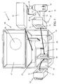
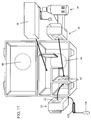
- Fig. 1 shows a power tool system according to a first aspect of the present teachings in an exploded view.
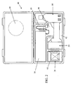
- Fig. 2 shows the power tool system of Fig. 1 with all components stored in their respective compartments.
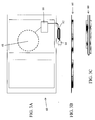
- Fig. 3A shows a top view of a representative base station for wirelessly supplying power to a storage case according to another aspect of the present teachings.
- Fig. 3B shows a front or side view of the base station of Fig. 3A.
- Fig. 3C shows the base station of Fig. 3B in a folded state for compact storage.
- Fig. 4 shows a modification of the base station of Fig. 3.
- Fig. 5 shows a plurality of storage cases stacked on top of a base station for charging the battery packs stored in the storage cases.
- Fig. 6 shows a base station modified to obtain power from a DC vehicle power source, wherein two storage cases are stacked on the base station for simultaneous transportation and charging of the battery packs stored therein.
- Fig. 7 shows another modification of the base station and a storage case to be stacked thereon.
- Fig. 8 shows the base station of Fig. 7 ready to be transported with storage cases stacked thereon.
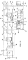
- Fig. 9 shows a representative circuit diagram for the base station, storage case and battery pack according to another aspect of the present teachings.
- Fig. 10 shows another representative circuit diagram with a modified base station.
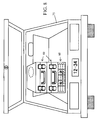
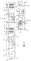
- Fig. 11 shows a modification of the base station and the storage case to include electrical contacts so that power is conducted or transmitted via a wired (direct) connection from the base station to the storage case(s).
- Fig. 12 shows a plurality of the storage cases of Fig. 11 stacked on the base station for charging the battery packs stored therein, wherein power is conducted or transmitted from one storage case to another storage case via one or more wired connections.
- Fig. 13 shows a modification of the base station with a storage case to be disposed thereon.
- Fig. 14 shows an enlarged view of the electrical contacts utilized in the embodiments of Figs. 11-13.
- Fig. 15 shows a representative circuit diagram for the base station, storage case and battery packs according to an aspect of the present teachings that utilizes direct electrical contacts between the base station and the storage case(s).
- Fig. 16 shows the storage case of Fig. 1 that is supplied with power via an AC power cord.
- Fig. 17 shows the storage case of Fig. 1 that is supplied with power via a DC power supply connector.
- Fig. 18 shows the storage case of Fig. 1 that includes a set of high-capacity, rechargeable battery cells for storing energy to charge the battery packs stored in the storage case.
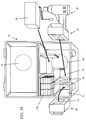
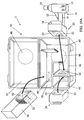
- Fig. 19A shows an exploded view of a power tool system according to another aspect of the present teachings, in which a charger is capable of wirelessly obtaining power and storing the power for subsequent use in charging a battery pack.
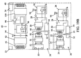
- Fig. 19B shows a representative circuit diagram for implementing the embodiment of Fig. 19A.
- Fig. 20 shows a modification of the storage case according to the present teachings so as to provide a plurality of compartments for storing and charging battery packs.
- Fig. 21 shows another modification of the storage case containing electrical contacts for charging the battery pack and an induction coil for wirelessly obtaining power from a base station or another storage case.
- Fig. 22 shows a representative circuit diagram for implementing the embodiment of Fig. 21.
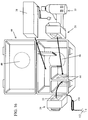
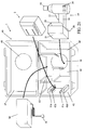
- Fig. 23 shows an adapter configured to wirelessly obtain power from a base station or a storage case and to detachably connect to a battery pack.
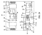
- Fig. 24 shows a representative circuit diagram for implementing the embodiment of Fig. 23.
- Fig. 25A shows a battery pack and another adapter for wireless charging in a separated state.
- Fig 25B shows the battery pack and the adapter of Fig. 25A in an assembled state.
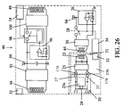
- Fig. 26 shows a representative circuit diagram for implementing the embodiment of Figs. 25A and 25B.
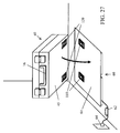
- Fig. 27 shows an embodiment similar to Fig. 11 in which the base station and the storage case each include electrical contacts so that power is conducted or transmitted via a wired (direct) connection from the base station to the storage case(s).
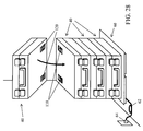
- Fig. 28 shows a plurality of the storage cases of Fig. 27 stacked on the base station for charging the battery packs stored therein, wherein power is conducted or transmitted from one storage case to another storage case via one or more wired connections.
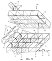
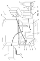
- Fig. 29 shows a storage case similar to the embodiment of Fig. 21, which containing electrical contacts for charging the battery pack, but in which the wired contacts according to Figs. 27 and 28 are utilized to obtain power from the base station or another storage case.
- controller(s) of the device which may be embodied with one or more processors (e.g., microprocessors) and memory/storage that stores programs and data to be executed by the processor(s).
- processors e.g., microprocessors
- memory/storage that stores programs and data to be executed by the processor(s).
- some or all of the above- or below-described functions may be implemented in analog circuitry, dedicated digital circuitry, e.g., a state machine, or mixed dedicated circuitry in any of the below-described exemplary embodiments, as would be well understood by a person of ordinary skill in the art after reading the present disclosure.
- Fig. 1 shows a first embodiment of a power tool system 1 according to the present teachings, which generally includes a power tool 10, two battery packs 20, a charger 38 and a storage case 40.
- the power tool 10 may be any type of battery-powered, portable tool, whether already known in the art or developed in the future, including but not limited to driver drills, impact drivers, circular saws, impact wrenches, reciprocating saws, jig saws, flashlights, blowers, trimmers, vacuums, miter saws, chain saws, band saws, staplers, grinders, sanders, buffers, concrete mixers (vibrators), radios, etc.
- such a power tool 10 includes a trigger 12 (or other manually-operated ON/OFF switch), an electric motor and an optional reduction gear transmission (not shown) disposed within a housing 14, a hand-grip or handle 16 and a battery holder 18.
- a tool 19 is driven by the motor/gear transmission to perform a power tool operation, e.g., cutting, drilling, tightening/loosening, mixing, sanding/grinding, illuminating, etc.
- the battery pack 20 is physically and electrically connectable to the battery holder 18 of the power tool 10 and includes one or more battery cells, as will be described in further detail below.
- the battery pack 20 also includes a first receiving antenna 22, which is configured to receive, take or absorb wirelessly-transmitted electric power, such as via a varying electromagnetic field (magnetic flux), utilizing, e.g., an inductive coupling (charging) technique or a resonant inductive coupling (charging) technique.
- a charger 38 may optionally be provided with the power tool system 1 and in this embodiment, it is powered by a commercial A/C power source via a plug 39. As will be further discussed below, the charger 38 may be configured to recharge the battery pack 20 by a wired or direct contact connection, as is well known in the art, and/or by wirelessly-transmitted power that is received by the first receiving antenna 22 of the battery pack 20 and is ultimately converted into a charging current. In this case, the charger 38 would include a transmitting antenna configured or adapted to wirelessly transmit power to a proximally-disposed battery pack 20, as will be further discussed below.
- the power tool system 1 of the present embodiment also includes a storage case 40, which may optionally be configured to transport the power tool 10, battery pack(s) 20 and the charger 38.
- the storage case 40 may include one or more of: a first compartment 41 designed to receive or accommodate a first battery pack 20 in a detached state, a second compartment 42 designed to receive or accommodate the power tool 10 while connected to a second battery pack 20 and/or a third compartment 43 designed to receive or accommodate the charger 38.
- Each compartment 41, 42, 43 may include a first transmitting antenna 44 configured or adapted to wirelessly transmit a source of power, such as an electromagnetic field, as will be further discussed below.
- the storage case 40 may optionally have only one, two or more first compartments 41. In the alternative, the storage case 40 may optionally have only one, two or more second compartments 42. In the alternative, the storage case 40 may optionally have only one, two or more third compartments 43.
- the present teachings encompass all possible combinations and numbers of first, second and third compartments 41, 42, 43, including the absence or omission of one or more of the first, second and third compartments 41, 42, 43.
- the first and/or second compartment(s) 41 and 42 is/are preferably arranged, configured and/or designed so that the first receiving antenna(s) 22 will be disposed proximal or adjacent to the first transmitting antenna(s) 44 when the battery pack(s) 20 is(are) disposed in the storage case 40.
- first receiving antenna(s) 22 will be disposed proximal or adjacent to the first transmitting antenna(s) 44 when the battery pack(s) 20 is(are) disposed in the storage case 40.
- the first receiving antenna 22 is disposed on, in or adjacent to the bottom surface (side) 21 of the battery pack 20, e.g., the surface of the battery pack 20 that is opposite of the surface that connects to the battery holder 18 of the power tool 10.
- the first compartment 41 may be configured to receive the first battery pack 20 such that the bottom surface (side) 21 of the battery pack 20 lies on the bottom surface (side) 45 of the storage case 40. That is, the first compartment 41 can be designed so that it prevents the battery pack 20 from being placed in the storage case 40 in a state in which the first receiving antenna 22 is not proximal or adjacent to the first transmitting antenna 44.
- the first receiving antenna 22 could instead be disposed, e.g., on a lateral side of the battery pack 20, in which case the first transmitting antenna 44 could also be disposed on the corresponding lateral or vertically-extending side of the first compartment 41 so that the first receiving antenna 22 will always be proximal to the first transmitting antenna 44 when the battery pack 20 is disposed in the first compartment 41.
- the outer contour of the battery pack 20 and the inner contour of the first compartment 41 could be designed so as to permit the battery pack 20 to be inserted in only one specific orientation.
- visual and/or written directions could be placed on an interior surface (e.g., the bottom surface 45) of the storage case 40 to provide instructions for the user with respect to the appropriate orientation of the battery pack 20 within the first compartment 41 to ensure the charging operation will proceed.
- the second compartment 42 may be configured or adapted to operate in the same functional manner as the first compartment 41 and thus the above-described teachings concerning wireless charging capabilities of the first compartment 41 are completely applicable to the second compartment 42. Thus, it is not necessary to repeat the functional aspects of the wireless charging capability of the second compartment 42 herein.
- the second compartment 42 may be constructed in a different manner because it is designed to accommodate the battery pack 20 while it is attached to the power tool 10 and is also designed to wirelessly charge the battery pack 20 in this attached state. Therefore, the second compartment 42 has larger dimensions than the first compartment 41 and preferably has an inner contour that matches or is at least substantially complementary to the outer contour of the combined power tool 10 and battery pack 20, so that the user is required to place the combined power tool 10 and battery pack 20 into the second compartment 42 in a particular orientation, i.e. the orientation that places the first receiving antenna 22 of the battery pack 20 proximal to the first transmitting antenna 44 of the second compartment 42.
- first receiving antenna 22 is disposed on, in or adjacent the bottom surface 21 of the battery pack 20. Therefore, first transmitting antenna 44 is disposed on a lateral or vertically-extending wall of the second compartment 42 in a position that will be proximal or adjacent to the first receiving antenna 22 when the power tool 10 and battery pack 20 are disposed in the second compartment 42.
- first transmitting and receiving antennae 22, 44 are possible within the scope of the present teachings and it is only necessary that the first transmitting and receiving antennae 22, 44 are disposed sufficiently close to each other in order to enable the wireless charging operation when the power tool 10 and battery pack 20 are disposed within second compartment 42. That is, the first transmitting and receiving antennae 22, 44 are preferably disposed at least substantially parallel to each other when the combined power tool 10 and battery pack 20 are disposed within second compartment 42. For example, if the first receiving antenna 22 is disposed on, in or adjacent to a lateral side of the battery pack 20, the first transmitting antenna 44 may be disposed either on or in the bottom side 45 of the case 40 (i.e. on the bottom side of the second compartment 42) or on another lateral side of the second compartment 42. All such other configurations are within the scope of the present teachings.
- the storage case 40 also requires a device for receiving or providing power (energy) in order to drive the first transmitting antenna(s) 44.
- a device for receiving or providing power (energy) in order to drive the first transmitting antenna(s) 44 is also required.
- the storage case 40 may include a second receiving antenna 46 disposed, e.g., in, on or adjacent to the bottom surface (side) 45 of the storage case 40.
- the second receiving antenna 46 may be configured to receive wirelessly-transmitted power from another power source, which may be a base station 60 for the storage case 40, as will be discussed further below with reference to Fig. 3, or even another storage case 40.
- the storage case 40 further (optionally) includes a second transmitting antenna 48 disposed in, on or adjacent to a top surface (side) 47 of the storage case 40.
- the second transmitting antenna 48 is configured to wirelessly transmit power, e.g., via an electromagnetic field, to the second receiving antenna 46 of another storage case 40 that is disposed above or adjacent to the top surface (side) 47 of the storage case 40.
- Such an embodiment will be described below in more detail with reference to Fig. 5.
- Fig. 2 shows the first battery pack 20, the power tool 10 with the connected second battery pack 20 and the charger 38 disposed within their respective compartments 41, 42, 43.
- the two first receiving antennas 22 are each superimposed on or overlap the respective first transmitting antennas 44, so that power can be wirelessly transferred to the battery packs 20, e.g., using resonant inductive coupling or another technique that employs near field wireless transmission of energy.
- Fig. 3A shows a top view of a first representative base station 60 configured to supply power to the storage case 40, i.e. ultimately to the first transmitting antennas 44 and to the second transmitting antenna 48, if provided, of the storage case 40.
- the base station 60 includes a power cord 62 and plug 64 configured or adapted to be inserted into an AC power source (e.g., an alternating current at 100-240 volts).
- the base station 60 also includes a second transmitting antenna 48.
- the second transmitting antenna 48 of the base station 60 and the second transmitting antenna 48 of the storage case 40 may have a same shape and specification.
- the base station 60 also includes a circuit 66 for driving the second transmitting antenna 48 of the base station 60 using the AC power supplied thereby, as is well known in the art.
- Figs. 3B and 3C show side or front views of the base station 60 in an optional embodiment, in which the base station 60 is foldable for convenient storage. Further, Figs. 3B and 3C indicate that the electronics (e.g., the second transmitting antenna 48 and circuit 66) for the base station 60 may be arranged in a relatively thin and/or planar manner to minimize space requirements.
- the electronics e.g., the second transmitting antenna 48 and circuit 66
- the base station 60 may include a plug 72 adapted or configured to be inserted into the DC power supply of a vehicle as shown in Fig. 6 and a circuit for driving the second transmitting antenna 48 using the DC power supplied thereby.
- the storage case 40 may be hard-wired to an appropriate AC and/or DC power supply and may include the necessary circuitry for driving the first transmitting antenna 44 and /or the second transmitting antenna 48 using the power supplied thereby.
- the storage case 40 may optionally be further designed to remain stationary, e.g., near an assembly line.
- the base station 60 may optionally include a power cord 62 and plug 68 configured or adapted to be inserted into a DC power source 70, such as a battery pack, and may further include the necessary circuitry 66a for driving the second transmitting antenna 48 using the DC power supplied thereby.
- a DC power source 70 such as a battery pack
- the base station 60 and the storage case 40 can be powered and can recharge the battery packs 20 in any circumstance, because neither an AC power source nor an external DC power source, e.g., generated by a vehicle, is necessary.
- Such a base station 60 enables continuous operation of the power tool 10, e.g., at a remote worksite without the need to operate a stand-alone generator.
- a plurality of storage cases 40 is shown in a stacked arrangement for charging and optionally also transportation.
- the base station 60 has been plugged into a commercial AC power source using the plug 64 and alternating current is supplied to the base station 60 via power cord 62.
- the base station 60 drives the second transmitting antenna 48 (shown in Fig. 3A) so as to generate a varying electromagnetic field and thereby supply power to the second receiving antenna 46 of the lowermost storage case 40.
- Each storage case 40 utilizes a portion of the supplied power to drive the first transmitting antenna(s) 44 disposed therein in order to charge the battery pack(s) 20 accommodated in the storage case 40.
- Each storage case 40 may also optionally utilize a portion of the supplied power to drive the second transmitting antenna(s) 48 disposed therein in order to supply power to the next storage case 40 placed on the top surface (side) 47 thereof.
- this embodiment makes it possible to charge the battery packs 20 in a plurality of storage cases 40 utilizing a single base station 60, thereby minimizing equipment costs in an advantageous manner.
- Fig. 6 shows a useful modification of the embodiment of Fig. 5, in which a plug 72 is provided that is configured to be connected to a DC power supply generated by a vehicle 75.
- the plug 72 may be configured to be inserted into a cigarette lighter or other power source connector provided in or on the vehicle 75.
- a power cord 74 supplies the DC power to the base station 60 for driving the transmitting antennas 44, 48 of the stacked storage cases 40.
- Fig. 7 shows another alternate embodiment of the base station 60 of the present teachings.
- a plurality of battery cells 76 e.g., high-capacity, rechargeable battery cells, are disposed within the base station 60 and supply energy for driving the second transmitting antenna 48 of the base station 60.
- one or more storage cases 40 may be stacked or disposed on the base station 60 of Fig. 7 so that the respective second receiving and transmitting antennas 46, 48 are superimposed or overlap to permit the efficient transfer of power in a wireless manner.
- the base station 60 of Fig. 7 also includes a handle 78 so that it can be conveniently carried, e.g., to a worksite, thereby eliminating the need for an AC power source or an external DC power source at the worksite.
- the base station 60 itself may be recharged according to any of the previously mentioned techniques, such as by plugging into a commercial AC power source or into another AC or DC power source, such as a generator of a vehicle or a portable generator.
- the self-powered base station 60 of Fig. 7 is portable and may be transported by a vehicle 75.
- the base station 60 may wirelessly supply power to the storage case(s) 40 while driving the vehicle 75 in order to recharge the battery packs 20 in a productive manner.
- a transmitting induction coil generates an alternating electromagnetic field from within the base station 60 or the storage case 40
- a receiving induction coil disposed in the battery pack 20 or the storage case 40 takes power from the varying electromagnetic field and converts it back into an electric current to charge the battery pack(s) 20 (via the first transmitting antenna 44) and/or to drive the second receiving antenna 46 of another storage case (via the second transmitting antenna 48).
- the first set of transmitting and receiving induction coils 44, 22 and the second set of transmitting and receiving induction coils 48, 46 cooperate according to the principles of an electronic transformer, i.e. the magnetic flux supplied by the transmitting antenna 44, 48 causes a voltage to be generated in the receiving antenna 22, 46, which results in a current flow when the receiving antenna 22, 46 is connected to a load.
- resonant inductive coupling techniques are utilized in order to permit greater distances between the transmitting and receiving antenna (coils) without loss of power.
- the wireless transfer of power is performed according to the Qi standard as defined by the Wireless Power Consortium (WPC).
- Fig. 9 illustrates a first representative system 1 that utilizes an AC power source 80 to supply the power for driving the electronics and charging the battery packs 20.
- the base station 60 includes a power cord 62 that is connectable to the AC power source 80.
- a fuse 82 may be provided to protect the circuitry from damaging power surcharges.
- An AC/DC converter 84 converts the alternating current into a direct current as is well known in the art.
- a circuit 86 is provided for measuring the amount of power that is being transmitted between the second transmitting antenna 48 of the base station 60 and the second receiving antenna 46 of the storage case 40, which are preferably induction coils in the present embodiment.
- the power measuring circuit 86 is electrically connected to the switching circuit 88.
- the switching circuit 88 is turned-off (opened) when the amount of power being transmitted between the second transmitting antenna 48 and the second receiving antenna 46 exceeds a predetermined rated or threshold value.
- the switching circuit 88 is also turned-off (opened) when the corresponding second receiving antenna 46 is not disposed proximal to the second transmitting antenna 48.
- a pair of sensing devices 32, 34 may be provided, as will be further described below.
- a circuit 90 generates high-frequency power for wireless transmission by resonant inductive coupling.
- the high-frequency power generated by the circuit 90 is supplied to the second transmitting antenna (induction coil) 48.
- the induction coil 48 is capable of generating a magnetic flux.
- the storage case 40 includes the second receiving antenna 46, which is also preferably an induction coil in the present embodiment.
- the two coils 46, 48 are each capacitively loaded so as to form a tuned LC circuit. If the transmitting coil (primary coil) 48 and the receiving coil (secondary coil) 46 resonate at a common frequency, power may be transmitted between the coils relatively efficiently.
- Each coil 46, 48 may be air cored to avoid losses associated with iron cores.
- Resonant transfer works by applying an oscillating current to the primary coil 48, thereby generating an oscillating or varying electromagnetic field (magnetic flux). If the secondary coil 46 is highly resonant, any energy placed in the coil 46 dissipates relatively slowly over many cycles. When the secondary coil 46 is disposed proximal to the primary coil 48, the secondary coil 46 absorbs or receives most of the energy before it is lost.
- the oscillating alternating current generated by the secondary coil 46 is converted into a positive voltage supply Vcc 94 by circuit 92 as is well known in the art, e.g., using a rectifier and a filter to provide a smoothed DC output.
- the positive voltage supply Vcc is then used by circuit 100 to generate high-frequency power for wireless transmission by resonant inductive coupling.
- the high-frequency power generated by the circuit 100 is supplied to the second transmitting antenna (induction coil) 48.
- the induction coil 48 wirelessly transmits power to the second receiving antenna 46 of another storage case 40.
- the high-frequency power generated by the circuit 100 is supplied to the second transmitting antenna (induction coil) 48.
- the induction coil 48 is capable of generating a magnetic flux.
- the circuit 100 preferably generates high-frequency power for wireless transmission by resonant inductive coupling.
- the power measuring circuit 96 is electrically connected to the switching circuit 98.
- the switching circuit 98 is turned-off (opened) when the amount of power being transmitted between the second transmitting antenna 48 of the storage case 40 and the second receiving antenna 46 of another storage case 40 exceeds a predetermined rated or threshold value.
- the switching circuit 98 is also turned-off (opened) when the corresponding second receiving antenna 46 is not disposed proximal to the second transmitting antenna 48.
- the positive voltage supply Vcc is also utilized to drive a circuit 30 and the first transmitting antenna (primary induction coil) 44 in order to recharge the battery pack 20. More specifically, the circuit 30 generates high-frequency power for wireless transmission by resonant inductive coupling. The high-frequency power generated by the circuit 30 is supplied to the first transmitting antenna (primary induction coil) 44. The induction coil 44 wirelessly transmits power to the first receiving antenna 22 within the battery pack 20.
- a switching circuit 28 is turned-off (opened) when a corresponding receiving antenna 22 of the battery pack 20 is not disposed proximal to the first transmitting antenna 44.
- the switching circuit 98 is also turned-off (opened) when the amount of power being transmitted between the first transmitting antenna 44 and the first receiving antenna 22 exceeds a predetermined rated or threshold value.
- the circuit 30 generates high-frequency power for wireless transmission by resonant inductive coupling.
- the high-frequency power generated by the circuit 30 is supplied to the first transmitting antenna (induction coil) 44.
- the primary induction coil 44 is capable of generating a magnetic flux and the secondary induction coil (receiving antenna) 22 receives the power wirelessly.
- Each of the power measuring circuits 86, 96, 26 preferably includes a comparator configured to compare a measured voltage to a reference voltage.
- Each of the switching circuits 88, 98, 28 preferably includes a switch, e.g., a FET, that is opened and closed based, at least in part, upon the output of the comparator.
- the switching circuit 88 permits an appropriate amount of current to pass to the primary induction coils 48 through the circuit 90.
- the switching circuit 98 permits an appropriate amount of current to pass to the primary induction coils 48 through the circuit 100.
- the switching circuit 28 permits an appropriate amount of current to pass to the primary induction coils 44 through the circuit 30.
- the first receiving antenna (secondary induction coil) 22 of the battery pack 20 absorbs the power transmitted via the oscillating electromagnetic field and supplies the resulting oscillating current to a charging controller 25 disposed in the battery pack 20.
- the charging controller 25 then charges the battery cell(s) 24 using the supplied current according to any charging protocol or program that is suitable for the battery cell(s) 24.
- the present teachings are not particularly limited in this respect.
- the battery pack 20 and the storage case 40 preferably include a proximity sensing device that actuates the wireless power transmission circuitry only when the secondary coil 22 of the battery pack 20 is disposed proximal to the primary coil 44 of the storage case 40, i.e. sufficiently close that the wireless transmission of power can be effected in an efficient manner.
- the battery pack 20 may further include a magnet 32, e.g., a permanent magnet, disposed in, on or proximal or to the bottom surface (side) 21 of the battery pack 20 and the storage case 40 may include a sensing device 34 configured or adapted to detect the magnetic field generated by the magnet 32.
- the magnetic field detecting device 34 may be, e.g., a reed switch or a Hall sensor. When the magnetic field detecting device 34 is actuated due to the close proximity of the magnet 32, the switching circuit 28 is turned-on (closed), and the wireless power transmitting circuitry is caused to begin operating, thereby initiating the charging of the battery cell(s) 24.
- the present teachings are not limited to proximity sensors that operate based upon magnetic fields.
- Various other types of proximity sensors may be employed with the present teachings, such as physical contact switches (e.g., push button switches), pressure or weight sensors configured or adapted to detect when the battery pack has been placed onto the bottom surface 45 of the storage case 40, electrical resistance or capacitive sensors that detect another circuit element being electrically connected thereto, radio frequency identification (RFID) devices, optical sensors, etc.
- RFID radio frequency identification
- one or both of the battery pack 20 and the storage case 40 may include an RFID interrogator and one or both of the battery pack 20 and the storage case 40 may include an RFID tag.
- the RFID interrogator detects the presence of the RFID tag and may initiate the supply of power and the charging operation.
- the RFID tag may be active, passive or battery-assisted passive. If the RFID tag is located in the battery pack 20, the RFID tag may also store information, such as the type of battery cells in the battery pack, the usage history of the battery pack and/or the charge state of the battery cells, which information can be read by the RFID interrogator located in the storage case 40. In this case, such information may be utilized to adjust or optimize the charging protocol, if necessary.
- the base station 60 and storage case 40 also may optionally include a proximity sensing circuit to detect when the secondary coil 46 of the storage case 40 has been brought into proximity with the primary coil 48 of the base station 60.
- the storage case 40 may include a permanent magnet 32 disposed on or adjacent its bottom surface (side) 45 and the base station 60 may include a reed switch or Hall sensor 34 disposed in, on or adjacent to its top surface (side) 61.
- the proximity sensing circuit of the base station 60 then preferably closes the switching circuit 88, and actuates the wireless power transmission circuitry of the base station 60 when the proximity sensor detects the close presence or proximity of the storage case 40.
- any type of suitable proximity sensing means may be utilized in this aspect of the present teachings, such as was further described above.
- each storage case 40 may include additional proximity sensing means configured or adapted to detect when a second storage case 40 has been disposed on top of a first storage case 40 so as to actuate the wireless power transmission circuitry 100 of the first storage case 40 and thereby supply energy to the secondary coil 46 of the second storage case 40.
- any type of suitable proximity sensing means may be utilized in this aspect of the present teachings, such as was further described above.
- each storage case 40 may include a reed switch or Hall sensor disposed in, on or adjacent its top surface (side) 47 that is configured to detect the presence of a magnet disposed on or adjacent the bottom surface 45 of the storage case 40 that is stacked thereon.
- one or both of the base station 60 and the storage case 40 may include an RFID interrogator and one or both of the base station 60 and the storage case 40 may include an RFID tag.
- the RFID interrogator detects the presence of the RFID tag and may initiate the supply of power from the base station 60 to the storage case 40.
- the RFID tag may be active, passive or battery-assisted passive.
- the RFID tag may also store information, such as the type of battery cells in the battery pack(s) 20 stored in the storage case 40, the usage history of the battery pack(s) 20 and/or the charge state of the battery pack(s) 20, which information can be read by the RFID interrogator located in the base station 60. In this case, such information may be utilized to adjust or optimize the power transmission protocol, if necessary.
- Fig. 10 shows a representative internal circuit diagram for implementing the portable base station 60 and the storage case 40 shown in Fig. 7.
- a plurality of high-capacity battery cells 76 supply a direct current to a DC voltage regulator 102, which converts the supplied voltage/current into a voltage/current that is appropriate for driving the wireless power transmission circuitry 86, 88, 90, which may operate in an identical manner, at least in principle, to the wireless power transmission circuitry 86, 88, 90 shown in Fig. 9. Therefore, it is not necessary to repeat the description of the wireless power transmission circuitry 86, 88, 90 herein.
- a battery monitor 104 may be provided to sense when the energy of the battery cells 76 has been depleted and to stop the supply of current from the battery cells 76 to the DC voltage regulator 102, e.g., by opening switch 106, so as to avoid over-discharging, and thus damaging, the battery cells 76.
- the electronics of the storage case 40 of the embodiment shown in Fig. 10 may be identical to the electronics of the storage case 40 of the embodiment shown in Fig. 9 and therefore, a description thereof need not be repeated.
- the base station 60 and the storage case 40 may also (or instead) have the capability of transmitting power via a wired or direct connection. That is, the base station 60 may include one or both of wireless and wired power transmitting structures and circuitry and the storage cases 40 may also include one or both of wireless and wired power transmitting (and/or receiving) structures.
- Figs. 11-14 show representative embodiments of the base station 60 and storage case(s) 40 having wired or direct electrical contacts for transmitting or conducting electric power therebetween.
- the base station 60 includes a power cord 62 having a plug 64 configured to connect to an AC power supply.
- Two male electrical contacts 110 are disposed on the top surface (side) 61 of the base station 60 in locations that physically or spatially correspond to two complementary female electrical contacts 120 disposed on the bottom surface (side) 45 of the storage case 40.
- While a single set of one male contact 110 and one female contact 120 may be provided on the surfaces of the base station 60 and storage case 40, two or more sets may be provided to ensure the two structures (i.e. the base station 60 and storage case 40 or two storage cases 40) are superimposed in the proper orientation for efficiently performing power-transmission and charging operations.
- the arrangement of the electrical contacts may be reversed, such that the male electrical contact(s) is(are) disposed on the bottom surface (side) 45 of the storage case 40 and the female electrical contact(s) is(are) disposed on the top surface (side) 61 of the base station 60.
- the electrical contacts 110, 120 may be physically located in any appropriate location that is consistent with the present teachings.
- electrical contacts 110 may also be provided on the top surface (side) 47 of the storage case 40 so as to engage corresponding or complementary electrical contacts 120 (e.g., female electrical contacts) disposed on the bottom surface (side) 45 of the storage case 40 stacked thereon.
- corresponding or complementary electrical contacts 120 e.g., female electrical contacts
- Fig. 13 shows a modified embodiment corresponding generally to the embodiment of Figs. 7 and 10, in which electrical contacts 110 are provided on the top surface (side) 61 of a base station 60 that includes a plurality of high-capacity battery cells 76, i.e. a self-contained power supply.
- Direct or wired electrical connections may be advantageous in such embodiments of the base station 60 that include a self-contained power supply (e.g., battery cells 76) in order to minimize power transmission losses.
- a self-contained power supply e.g., battery cells 76
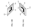
- Figs. 14A and 14B show the representative male and female electrical contacts 110, 120, respectively, in an enlarged view.
- the male electrical contact 110 is designed to be entirely complementary to the female electrical contact 120 to ensure a reliable fitting of the storage case 40 with the base station 60 (or another storage case 40).
- the electrical contacts 110, 120 can prevent the upper storage case 40 from rotating and/or laterally displacing relative to the lower base station 60 (or lower storage case 40), thereby ensuring that the electrical connection is reliably maintained during transport of the structures, e.g., in a vehicle.
- By reliably maintaining the electrical connection it is ensured that charging of the battery pack(s) 20 can be adequately performed during transport, thereby improving productivity because the battery packs can be charged while moving to/from the worksite.
- the exemplary male electrical contact 110 includes a rectangular-shaped protrusion 112 disposed generally in the middle.
- the protrusion 112 is surrounded by a rectangular-shaped recess 114, which is in turn surrounded by a rectangular-shaped wall 116.
- An electrode 118 for conducting current may be disposed on the top and/or lateral side(s) of the protrusion 112.
- the wall 116 preferably surrounds the electrode 118 so as to prevent short circuits.
- the complementary female electrical contact 120 shown in Fig. 14B includes a rectangular-shaped depression 122 defined in the middle and surrounded by a rectangular-shaped ridge 124.
- a rectangular-shaped groove 126 is defined around the rectangular-shaped ridge 124.
- An electrode 128 may be disposed on the surface of the depression 122 and/or on the inner lateral side(s) of the rectangular-shaped ridge 124.
- the protrusion 112 fits in the depression 122 in an interlocking, interference or form-fit manner
- the rectangular-shaped ridge 124 fits in the recess 114 in an interlocking, interference or form-fit manner
- the wall 116 fits in the groove 126 in an interlocking, interference or form-fit manner.
- the electrode 118 of the male electrical contact 110 is disposed so as to physically contact the electrode 128 of the female electrical contact 120 when the two electrical contacts 110, 120 are brought into engagement.
- Fig. 15 shows an internal circuit diagram of the base station 60 and storage case(s) 40 that utilize direct electrical contacts 110, 120.
- the circuit 90 and the primary coil 48 shown in Fig. 9 may be omitted from the base station 60.
- the secondary coil 46 and the circuit 92 shown in Fig. 9 may be omitted from the storage case 40.
- the circuit 100 and the primary coil 48 shown in Fig. 9 may be omitted from the storage case 40.
- direct connections provided by the electrical contacts 110, 120 may be utilized.
- the pair of sensing devices 32, 34 also may be omitted, although the base station 60 and/or the storage case 40 preferably includes a circuit configured to detect that the respective electrical contacts 110, 120 have been connected in order to initiate the supply of current from the base station 60 to the storage case 40 and/or from one storage case 40 to another storage case 40.
- a circuit configured to detect that the respective electrical contacts 110, 120 have been connected in order to initiate the supply of current from the base station 60 to the storage case 40 and/or from one storage case 40 to another storage case 40.
- an electrical resistance or capacitance sensor may optionally be utilized, although naturally any of the other sensing means described above or below may be utilized in this embodiment as well.
- the wireless charging of the battery pack 20 may be performed in any of the manners described above or below, which description is incorporated into this exemplary embodiment by reference.
- power may be supplied to the storage case 40 via a variety of other power sources, e.g., via a wired connection to one or more other power sources.
- the storage case 40 may include a power cord 150 and a plug 152 configured or adapted to be inserted into an AC power source (e.g., an alternating current at 100-240 volts) and a corresponding circuit for driving the first transmitting antenna(s) 44 (as well as the optional second transmitting antenna 48, if provided) using the AC power supplied thereby.
- an AC power source e.g., an alternating current at 100-240 volts
- a corresponding circuit for driving the first transmitting antenna(s) 44 (as well as the optional second transmitting antenna 48, if provided) using the AC power supplied thereby.
- the storage case 40 may include a power cord 150 and a plug 154 configured or adapted to be inserted into the DC power supply of a vehicle and a corresponding circuit for driving the first transmitting antenna(s) 44 (as well as the optional second transmitting antenna 48, if provided) using the DC power supplied thereby.
- the storage case 40 may include a plurality of high-capacity battery cells 156 and may include the necessary circuitry for driving the first transmitting antenna(s) 44 (as well as the optional second transmitting antenna 48, if provided) using the power supplied thereby.
- This embodiment provides the advantage that, even if no base station 60 or external power source is available, the battery pack(s) 20 can be recharged by placing the battery pack(s) 20 in the corresponding compartments 41, 42 of the storage case 40.
- the battery cells 156 preferably store sufficient energy to recharge the battery pack(s) 20 once or several times, preferably at least five times, more preferably at least ten times.
- the charger 38 may include one or more battery cells 52 for storing sufficient energy to recharge the battery pack(s) 20 once or several times without being electrically connected to another AC or DC power supply.
- the battery cell(s) 52 preferably store(s) sufficient energy to recharge the battery pack(s) 20 more than five times and even more preferably more than ten times.
- the battery cell(s) 52 may utilize a different battery chemistry and/or capacity than the battery cell(s) 24 of the battery pack 20, because the charger 38 may be configured to output lower currents than the power tool 10 may require during operation (i.e. the battery packs 20 are generally required to be capable of outputting a larger current than the charger 38). Therefore, the battery cell(s) 52 may have a higher charge storage density than the battery cell(s) 24, thereby reducing weight requirements for the charger 38 and/or enabling a greater amount of energy to be stored in the charger 38 for charging purposes.
- the charger 38 may also include a power receiving antenna (secondary induction coil) 50 that enables the battery cell(s) 52 to be recharged wirelessly.
- the charger 38 may include a circuit 51 for converting power received via the power receiving antenna 50 into a direct current (DC) and a circuit 53 configured to control the charging operation of the internal battery cell(s) 50 and/or the battery pack 20.
- the battery cells 52 in the charger 38 may be recharged via another power transmitting antenna 44 disposed in, on or adjacent to a wall of the third compartment 43, or may be recharged via a wired (direct) electrical connection to the base station 60 or another storage case 40.
- the power transmitting antenna 44 is preferably disposed within the third compartment 43 so that it will be proximal, e.g., parallel, to the power receiving antenna 50 when the charger 38 is disposed in the third compartment 43.
- first and second compartments 41 such as the preferred orientations of the antenna 44, 50 as well as any guides, walls or restrictions in the third compartment 43 that will require the charger 38 to be inserted into the third compartment 43 in a particular orientation, are equally applicable to the third compartment 43 and are incorporated herein by reference.
- the charger 38 and the storage 40 may optionally also include a pair of devices 32, 34 configured or adapted to detect the proximity of the power receiving antenna 50 to the corresponding power transmitting antenna 44 disposed in the storage case 40 in order to initiate the wireless transmission of power from the storage case 40 (i.e. from power transmitting antenna 44) to the charger 38 (i.e. to the power receiving antenna 50).
- a pair of devices 32, 34 configured or adapted to detect the proximity of the power receiving antenna 50 to the corresponding power transmitting antenna 44 disposed in the storage case 40 in order to initiate the wireless transmission of power from the storage case 40 (i.e. from power transmitting antenna 44) to the charger 38 (i.e. to the power receiving antenna 50).
- Any of the proximity sensing devices mentioned above or below may be utilized in this exemplary embodiment as well, and the description thereof is incorporated into this embodiment by reference.
- the antennae 44, 50 of the third compartment 43 and charger 38 may also each comprise an induction coil and the power may be transmitted via induction coupling, more preferably resonant induction coupling, as was described in greater detail above. All of these teachings provided herein concerning the wireless transmission of power are equally applicable to the present exemplary embodiment and are incorporated into the present exemplary embodiment.
- the battery pack 20, storage case 40 and base station 60 may be configured and/or may operate in any of the manners described above or below in the other exemplary embodiments, which description is fully applicable to the present exemplary embodiment and is incorporated herein.
- the exemplary storage case 40 may be further modified to hold and recharge a plurality of battery packs 20 as shown in Fig. 20.
- the storage case (or tray) 140 shown in Fig. 20 includes a plurality of first compartments 41, each configured to accommodate a single battery pack 20 in a particular orientation, e.g., with the bottom surface (side) 21 of the battery pack 20 facing downward so that the first receiving antenna 22 of the battery pack 20 is proximal to the first transmitting antenna 44 disposed in, on or adjacent to the bottom surface (side) of the first compartment 41.
- Each battery pack 20 and first compartment 41 also preferably includes one or more proximity sensing devices, as was discussed in greater detail above with respect to Fig. 9.
- any type of suitable proximity sensing means may be utilized in this aspect of the present teachings, such as magnetic sensors, pressure or weight sensors, physical contact (mechanical) sensors, optical sensors, RFID devices, electric sensors, etc., as long as it can detect when a battery pack 20 has been placed into the first compartment 41 so as to initiate the charging operation.
- Power may be supplied to the storage case 140 in any of the ways that were described above.
- power may be supplied via a plug 64 and power cord 62 configured or adapted to be connected to an AC power supply, or via a connection to a DC power supply, such as the DC power supply of a vehicle.
- a second receiving antenna (induction coil) 46 may be provided in the same manner as was described above with respect to Figs. 1 and 9.
- An optional second transmitting antenna (induction coil) 48 also may be provided in the same manner as was described above with respect to Figs. 1 and 9, so that the storage cases 140 may be stacked and power may be transmitted wirelessly from a lower storage case 140 to a storage case 140 stacked thereon.
- electrical contacts may be provided on the upper and lower surfaces of the storage cases 140 in the manner described above with respect to Figs.
- each storage case 140 in order to supply the necessary oscillating current to the respective induction coils 46 for charging the battery packs 20.
- the storage case 40 receives power wirelessly from a base station 60 or another storage case 40, as was described above. Therefore, all of the teachings provided above concerning wireless transmission of power from the base station 60 to the storage case 40 and/or from a first storage case 40 to a second storage case 60 are equally applicable to the present exemplary embodiment and are thus incorporated into this embodiment by reference, such that a repetitive description of the wireless charging circuitry and functions may be omitted.
- the present exemplary embodiment differs from the above-described embodiments in that the battery pack 20 physically engages a charging cradle 41a, 41b, 41c, 41d disposed in the first compartment 41 and the charging current is supplied to the battery pack 20 via a wired or direct connection.
- the charging cradle 41a, 41b, 41c, 41d may be configured to physically engage with and electrically connect to the battery terminals 36 provided on the battery pack 20, which are normally used to electrically connect the battery pack 20 to the power tool 10 or to a charger 38 having charging terminals.
- charging of the battery pack 20 can be performed according to known wired charging techniques in which a charging current is supplied to the battery cell(s) 24 via the direct connection established by the battery terminals 36 and the charging cradle 41a, 41b, 41c, 41d disposed in the first compartment 41.
- the first set of battery terminals is dedicated to connecting and supplying power to the power tool 10 and the second set of battery terminals 36 is dedicated to being connected to the charging cradle 41a, 41b, 41c, 41d and/or to a charging cradle on a charger 38.
- the battery pack 20 may include a charging controller 25a configured or adapted to control the battery charging operation or a charging controller may be provided in the storage case 40 in order to generate the appropriate charging current(s) to be supplied to the battery cell(s) 24.
- the battery pack 20, storage case 40 and base station 60 may be configured and/or may operate in any of the manners described above or below in the other exemplary embodiments, which description is fully applicable to the present exemplary embodiment and is incorporated herein.
- the battery pack 20 itself is not required to include or contain (internally) the means for receiving wireless-transmitted power.
- an adapter 170 may be provided that includes, e.g., at least the first receiving antenna (e.g., an induction coil) 22 and a controller 25 configured to generate a current, e.g., a direct current (DC), from the power absorbed by the first receiving antenna 22.
- a current e.g., a direct current (DC)
- the adapter 170 may simply supply such current to the battery pack 20, in which case the controller 25a in the battery pack 20 is preferably configured to generate an appropriate charging current for charging the battery cell(s) 24 therefrom, or the controller 25 may be further adapted to generate the appropriate charging current for charging the battery cell(s) 24 of the battery pack 20.
- the adapter 170 may be connected to a known battery pack and then the combined adapter/battery pack 170, 20 is placed together into the storage case 40, which may be any of the storage cases 40 described above or below, all of which are incorporated into the present exemplary embodiment.
- the electromagnetic field (magnetic flux) generated by the first transmitting antenna 44 thus induces a current in the first receiving antenna 22 disposed in the adapter 170, which current is ultimately utilized to recharge the battery cell(s) 24 in the battery pack 20.
- the adapter 170 may have a cavity 171 configured to at least partially receive and/or accommodate the battery pack 20 therein.
- the upper wall 172 of the cavity 171 may have the same or substantially the same shape (contour) as the battery holder 18 of the power tool 10, as was described above.
- the adapter 170 and the battery pack 20 will be physically and electrically connected in the same manner as known connections between a battery pack and a power tool, such as battery terminals 36 on the battery pack 20 and power terminals 174 on the adapter 170.
- a top side or surface 173 of the adapter 170 may have the same or substantially the same shape or configuration as the battery pack 20.
- the adapter 170 can be mounted directly onto the battery holder 18 of the power tool 10. That is, the user has the option of mounting the combined battery pack 20 and adapter 170 on the battery holder 18 of the power tool 10 or the user can remove the adapter 170 when not needed for charging purposes in order to directly mount the battery pack 20 on the battery holder 18 of the power tool 10 (i.e without an intervening adapter 170).
- the adapter 170 includes battery terminals and a controller communication port so that power and controller signals can be communicated from the battery pack 20 to the power tool 10 via the adapter 170.
- the adapter 170 is not required to include a power tool mounting portion and instead may be provided only to temporarily attach to the battery pack 20 so that the battery cell(s) 24 can be recharged using power wirelessly transmitted from the storage case 40 or another source, such as a charging base station.
- the adapter 170 may be affixed (detachably or permanently) to the bottom surface (or a side surface, as appropriate) of the battery pack 20.
- the battery pack 20 preferably includes a second set of battery terminals 37 on its bottom surface. These battery terminals 37 are different than the battery terminals 36 that are configured to electrically connect to the power tool 10.
- the second set of battery terminals 37 is dedicated for the function of receiving a current from the adapter 170 in order to recharge the battery cell(s) 24, as was discussed above.
- a power transmitting circuit may be established via antennae 22, 44 when the combined adapter/battery pack 170, 20 is placed together into the storage case 40, e.g., into the first compartment 41 thereof.
- the battery pack 20, storage case 40, base station 60 and adapter 170 may be configured and/or may operate in any of the manners described above or below in the other exemplary embodiments, which description is fully applicable to the present exemplary embodiment and is incorporated herein.
- While the exemplary embodiments of the present teachings have utilized resonant inductive coupling or electrodynamic induction to wirelessly transmit power, other types of near field wireless transmission of electrical energy may be utilized as appropriate.
- the present teachings also are not limited in this respect and other possible forms of wireless power transmission include, but are not limited to, electromagnetic radiation, such as microwave or laser transmission or electrostatic induction.
- lithium-based battery cells 24 in the battery packs 20 and/or in the self-contained power supplies 76, 156 of the storage case 40 or base station 60, in particular lithium ion battery cells
- the present teachings are not particularly limited in this regard and the battery cells may utilize any other suitable battery chemistry, such as, e.g., lithium metal oxide, lithium polymer, nickel metal hydride, nickel cadmium, lithium metal phosphate, lithium sulfur, solar cell or fuel cell.
- the storage cases 40, 140 are configured to be stacked on the base station 60 and/or one on top of another in the above-described detailed embodiments, other arrangements are possible within the scope of the present teachings.
- the storage cases 40, 140 and/or base station 60 may be disposed laterally or side-by-side. It is sufficient if the base station 60 and storage case(s) 40, 140 are disposed proximally to each other so that power can be efficiently transmitted.
- wired contacts 110, 120 are utilized to transfer power from a base station 60 to a case 40 as well as from case 40 to case 40, similar to the embodiment described with respect to Figs 11-14 above and incorporated herein, and also wired contacts 41a-d are utilized to charge the battery pack(s) 20 stored in the case 40, similar to the embodiment described with respect to Figs 21-22 above and incorporated herein.
- Figs. 27-29 show such an embodiment, which includes a base station 60 is electrically connected to an AC power supply via a cord 62 and plug 64.
- the base station 60 includes at least one (e.g., male) electrical contact 110 configured to supply current to at least one (e.g., female) electrical contact 120 disposed on or in a surface of a case 40 having a carrying handle 16.
- Each case 40 also includes at least one (e.g., male) electrical contact 110 configured to supply current to another case 40 when brought into contact therewith as shown in Fig. 28.
- the one electrical contact 110 is preferably provided on one side of the case 40 and the other electrical contact 120 is preferably provided on the other side of the case 40, so that multiple cases 40 may be stacked or disposed side-by-side.
- the electrical contacts 110, 120 are detachably contactable so that current can be transferred from case-to-case via the contacts 110, 120.
- the base station 60 thus provides a common power source for supplying current (power) to two or more cases 40.
- At least one charging cradle (port) 41a-d is provided to charge a battery pack 20 via a wired connection.
- Two or more charging cradles (ports) 41a-d may be provided in one case 40 so that two or more battery packs 20 may be simultaneously charged.
- a battery pack configured or adapted to be attached to, and drive, a power tool, e.g., a hand-held power tool, the battery pack comprising: at least one rechargeable battery cell, means for receiving wirelessly-transmitted power, and a circuit configured to convert wirelessly-transmitted power received by the receiving means into a charging current and to supply the charging current to the at least one rechargeable battery cell.
- the at least one rechargeable battery cell comprises a plurality of series-connected battery cells configured or adapted to output a nominal power of at least 300 Watts.
- the at least one rechargeable battery cell comprises a plurality of series-connected battery cells configured or adapted to output a nominal power of at least 600 Watts.
- the battery pack according to any preceding embodiment further having a nominal voltage greater than 10 volts.
- the battery pack according to any preceding embodiment further having a nominal voltage between 10-40 volts, e.g., between about 14 to 30 volts, e.g., between about 21 to 30 volts.
- the battery pack comprises lithium-based battery cells, e.g., five to ten battery cells, e.g., lithium-ion battery cells.
- the battery pack according to any preceding embodiment further having a nominal capacity of at least 0.5 amp-hour, e.g., equal to or more than 1.0 amp-hour, e.g., equal to or greater than 2.0 amp-hour.
- the battery pack according to any preceding embodiment, further comprising one or more of: battery terminals configured or adapted to be electrically connected to battery terminals of the power tool, a controller communication port, engaging means, such as slide rails, for engaging the battery pack with a battery holder of the power tool and/or locking means, such as a user-operable latch, for detachably locking the battery pack to the power tool.
- the proximity sensing device comprises an RFID device, e.g., an RFID tag and/or an RFID interrogator.
- the means for receiving wirelessly-transmitted power and the circuit configured to convert wirelessly-transmitted power received by the receiving means into a charging current and to supply the charging current to the at least one rechargeable battery cell are disposed within a adapter detachably connected to the at least one battery cell.
- the adapter comprises: first battery terminals configured or adapted to be electrically connected to battery terminals of the power tool, and second battery terminals configured or adapted to be electrically connected to battery terminals of the at least one battery cell.
- the battery pack according to embodiment 17, wherein the adapter comprises: battery terminals configured or adapted to be electrically connected to a first set of terminals on the battery pack that are in electrical communication with the at least one battery cell.
- the battery pack according to embodiment 18a, wherein the battery pack comprises: a second set of battery terminals configured or adapted to be electrically connected to battery terminals of the power tool.
- An adapter configured to detachably connect to a battery pack comprising at least one rechargeable battery cell, the adapter comprising: means for receiving wirelessly-transmitted power, and a circuit configured to convert wirelessly-transmitted power received by the receiving means into a current, e.g., into a charging current, and to supply the current to the at least one rechargeable battery cell.
- the at least one rechargeable battery cell comprises a plurality of series-connected battery cells configured or adapted to output a nominal power of at least 300 Watts, the battery cells optionally having a nominal voltage greater than 10 volts, e.g., between 10-40 volts, e.g., between about 14 to 30 volts, e.g., between about 21 to 30 volts.
- first engaging means such as slide rails
- second engaging means such as slide rails
- locking means such as a user-operable latch
- battery terminals configured or adapted to supply the current, e.g., the charging current, to terminals on the battery pack in communication with the at least one rechargeable battery cell, and means for physically engaging the adapter with the battery pack.
- the adapter according to any one of embodiments 20-25, further comprising a proximity sensing device disposed in or on the battery pack, e.g., one or more of a permanent magnet, an RFID tag and/or an RFID interrogator.
- a proximity sensing device disposed in or on the battery pack, e.g., one or more of a permanent magnet, an RFID tag and/or an RFID interrogator.
- a power tool system or kit comprising: a battery-powered tool, e.g., a hand-held power tool, configured to have a nominal power output of at least 400 Watts, more preferably at least 500 Watts, even more preferably at least 600 Watts and the battery pack according to any one of embodiments 1-19 or the adapter according to any one of embodiments 20-27.
- a battery-powered tool e.g., a hand-held power tool
- the battery-powered tool comprises a tool housing, an electric motor and transmission disposed within the tool housing, a trigger configured to actuate the electric motor to drive the transmission and a battery holder configured to detachably attach to the battery pack and/or to the adapter.
- a battery pack system comprising: at least one battery pack configured or adapted to be detachably engaged with a power tool, e.g., a hand-held power tool, the at least one battery pack comprising at least one battery cell, at least one first means for receiving wirelessly transmitted power and a circuit configured to charge the at least one battery cell using the wirelessly transmitted power, and a storage case configured to accommodate the at least one battery pack and comprising at least one first means for wirelessly transmitting power to the at least one first means for receiving wirelessly transmitted power of the at least one battery pack.
- the base station comprises at least one second means for wirelessly transmitting power
- the storage case comprises at least one second means for receiving wirelessly transmitted power from the at least one second means for wirelessly transmitting power.
- the storage case further comprises: at least one second means for wirelessly transmitting power to at least one second means for receiving wirelessly transmitted power of an adjacent storage case.
- the base station comprises at least one first electrical contact for transmitting power via a direct (wired) connection
- the storage case comprises at least one second electrical contact for receiving power via a direct (wired) connection with the base station, the at least one first electrical contact being complementary to the at least one second electrical contact.
- the base station further comprises at least one self-contained power supply configured to supply power to the storage case, wherein the at least one self-contained power supply comprises one or more battery cells, fuel cells or solar cells, preferably rechargeable lithium-based battery cells.
- the base station further comprises at least one power cord configured to be connected to an external power supply, such as an AC power supply, e.g., a commercial AC power supply, and/or to a DC power supply, e.g., the DC power supply of a vehicle.
- an external power supply such as an AC power supply, e.g., a commercial AC power supply
- a DC power supply e.g., the DC power supply of a vehicle.
- the storage case comprises at least one first compartment configured to accommodate only one battery pack detached from a power tool, the at least one first means for wirelessly transmitting power being disposed in or on the first compartment, e.g., in, on or adjacent to a bottom surface (side) of the first compartment.
- the storage case comprises a plurality of the first compartments configured to respectively accommodate a plurality of battery packs, each first compartment comprising at least one first means for wirelessly transmitting power to the battery pack accommodated therein, e.g., in, on or adjacent to a bottom surface (side) of the first compartment.
- the storage case comprises at least one second compartment configured to accommodate the battery pack while being attached to the power tool, the at least one first means for wirelessly transmitting power being disposed in or on the second compartment, e.g., in, on or adjacent to a lateral surface of the second compartment.
- the storage case further comprises at least one sensor configured or adapted to sense the presence and/or absence of a battery pack disposed proximal to the at least one first means for wirelessly transmitting power.
- the at least one sensor comprises one or more of: a reed switch, a Hall sensor, an optical sensor, a mechanical switch actuated by physical contact, a pressure or weight sensor, a radio frequency identification (RFID) device, e.g., an RFID interrogator, and/or an electric resistance or capacitive sensor.
- RFID radio frequency identification
- the at least one battery pack further comprises a permanent magnet and/or an RFID tag and the storage case comprises at least one sensor configured to detect the presence or absence of the magnet, e.g., a reed switch or a Hall sensor, and/or the RFID tag, e.g., an RFID interrogator.
- each of the at least one first means for receiving wirelessly transmitted power and the at least one first means for wirelessly transmitting power comprises an induction coil.
- each of the at least one second means for receiving wirelessly transmitted power and the at least one second means for wirelessly transmitting power comprises an induction coil.
- the battery pack charger comprises a self-contained set of rechargeable battery cells and a circuit for recharging the at least one battery cell of the at least one battery pack using power supplied by the self-contained set of rechargeable battery cells.
- the battery pack charger further comprises a third means for receiving wirelessly transmitted power and a circuit for charging the self-contained set of rechargeable battery cells using power supplied by the wirelessly transmitted power.
- the battery pack comprises: a first portion containing the at least one battery cell, and a second portion containing the at least one first means for receiving wirelessly transmitted power and the circuit configured to charge the at least one battery cell using the wirelessly transmitted power.
- the second portion further comprises: a first set of battery terminals configured or adapted to electrically connect with corresponding battery terminals of the first portion, and a second set of battery terminals configured or adapted to electrically connect with corresponding battery terminals of the power tool, the first set of battery terminals being in electrical communication with the second set of battery terminals so as to conduct power from the at least one battery cell to the power tool.
- the battery pack comprises: a first set of terminals configured to connect to a set of terminals on the power tool to supply power to the power tool and a second set of terminals configured or adapted to connect to a set of battery terminals on the adapter that are configured or adapted to supply current, e.g., a charging current, to the battery pack.
- a method for recharging a battery pack configured for use with a power tool comprising: placing the battery pack into a compartment of a first storage case or tray, generating an electromagnetic field in the compartment, generating a charging current using power obtained from the electromagnetic field, and charging at least one battery cell in the battery pack using the charging current.
- the proximity sensor comprises one or more of: a reed switch, a Hall sensor, an optical sensor, a mechanical switch actuated by physical contact, a pressure or weight sensor, a radio frequency identification (RFID) device, e.g., an RFID interrogator, and/or an electric resistance or capacitive sensor.
- RFID radio frequency identification
- the self-contained power source comprises at least one rechargeable battery cell.
- the at least one battery cell comprises a plurality of series-connected battery cells configured or adapted to output a nominal power of at least 300 Watts.
- the at least one battery cell comprises a plurality of series-connected battery cells configured or adapted to output a nominal power of at least 600 Watts.
- the battery pack has a nominal voltage between 10-40 volts, e.g., between about 14 to 30 volts, e.g., between about 21 to 30 volts.
- the battery pack comprises lithium-based battery cells, e.g., five to fifteen battery cells, e.g., lithium-ion battery cells.
- the battery pack comprises six to eight lithium-ion battery cells.
- the battery pack has a nominal capacity of at least 0.5 amp-hour, e.g., equal to or more than 1.0 amp-hour, e.g., equal to or greater than 2.0 amp-hour.
- a battery pack system comprising: at least one battery pack configured or adapted to be detachably engaged with a power tool, e.g., a hand-held power tool, the at least one battery pack comprising at least one battery cell and battery terminals, and a storage case configured to accommodate the at least one battery pack and comprising charging terminals configured to directly contact the battery terminals, at least one first means for receiving wirelessly transmitted power and a circuit configured to convert the wirelessly received power into a charging current that is supplied to the charging terminals.
- the battery pack system according to embodiment 89, further comprising: a base station configured or adapted to supply power to the storage case when the storage case is disposed proximal to the base station.
- the base station comprises at least one means for wirelessly transmitting power to the at least one first means for receiving wirelessly transmitted power.
- the storage case further comprises: at least one second means for wirelessly transmitting power to at least one first means for receiving wirelessly transmitted power of an adjacent storage case.
- the base station further comprises at least one self-contained power supply configured to supply power to the storage case, wherein the at least one self-contained power supply comprises one or more battery cells, preferably rechargeable lithium-based battery cells.
- the base station further comprises at least one power cord configured to be connected to an external power supply, such as an AC power supply, e.g., a commercial AC power supply, and/or to a DC power supply, e.g., the DC power supply of a vehicle.
- an external power supply such as an AC power supply, e.g., a commercial AC power supply
- a DC power supply e.g., the DC power supply of a vehicle.
- the storage case and/or the base station further comprises at least one sensor configured or adapted to sense the presence and/or absence of the base station disposed proximal to the at least one first means for receiving wirelessly transmitted power.
- the at least one sensor comprises one or more of: a reed switch, a Hall sensor, an optical sensor, a mechanical switch actuated by physical contact, a pressure or weight sensor, a radio frequency identification (RFID) device, e.g., an RFID interrogator, and/or an electric resistance or capacitive sensor.
- RFID radio frequency identification
- the battery pack system according to embodiment 95 or 96, wherein the storage case further comprises a permanent magnet and/or an RFID tag and the base station comprises at least one sensor configured to detect the presence or absence of the magnet, e.g., a reed switch or a Hall sensor, and/or the RFID tag, e.g., an RFID interrogator.
- the magnet e.g., a reed switch or a Hall sensor
- the RFID tag e.g., an RFID interrogator.
- each of the at least one first means for receiving wirelessly transmitted power and the at least one first means for wirelessly transmitting power comprises an induction coil.
- a method for recharging a battery pack configured for use with a power tool comprising: engaging battery terminals of the battery pack with charging terminals of a first storage case or tray, generating an electromagnetic field adjacent to the first storage case, generating a charging current using power obtained from the electromagnetic field, and charging at least one battery cell in the battery pack using the charging current.
- the proximity sensor comprises one or more of: a reed switch, a Hall sensor, an optical sensor, a mechanical switch actuated by physical contact, a pressure or weight sensor, a radio frequency identification (RFID) device, e.g., an RFID interrogator, and/or an electric resistance or capacitive sensor.
- RFID radio frequency identification
- the self-contained power source comprises at least one rechargeable battery cell.
- the method according to embodiment 109 or 110 further comprising: disposing a third storage case proximal to the second storage case, e.g., on top of the second storage case, and transmitting power from the second storage case to the third storage case for recharging a battery pack stored in the third storage case.
- the at least one battery cell comprises a plurality of series-connected battery cells configured or adapted to output a nominal power of at least 300 Watts.
- the at least one battery cell comprises a plurality of series-connected battery cells configured or adapted to output a nominal power of at least 600 Watts.
- the battery pack has a nominal voltage between 10-40 volts, e.g., between about 14 to 30 volts, e.g., between about 21 to 30 volts.
- the battery pack comprises lithium-based battery cells, e.g., five to fifteen battery cells, e.g., lithium-ion battery cells.
- the battery pack comprises six to eight lithium-ion battery cells.
- the battery pack has a nominal capacity of at least 0.5 amp-hour, e.g., equal to or more than 1.0 amp-hour, e.g., equal to or greater than 2.0 amp-hour.
- a charger configured or adapted to recharge a battery pack of a power tool, e.g., a hand-held power tool, the charger comprising: at least one rechargeable battery cell, and means for wirelessly transmitting power using energy from the at least one rechargeable battery cell to a means for receiving wirelessly transmitted power disposed in the battery pack.
- the battery pack is configured or adapted to output a nominal power of at least 300 Watts and the at least one rechargeable battery cell of the charger comprises a plurality of series-connected battery cells configured or adapted to completely recharge the battery pack at least once, more preferably at least twice, more preferably at least five times and even more preferably at least ten times.
- the charger according to any one of embodiments 126-129, wherein the charger comprises lithium-based battery cells, e.g., lithium-ion battery cells.
- the charger according to any one of embodiments 126-132, further comprising: means for receiving wirelessly-transmitted power, and a circuit configured to convert wirelessly-transmitted power received by the receiving means into a charging current and to supply the charging current to the at least one rechargeable battery cell.
- the charger according to embodiment 133 further comprising: at least one first sensor configured or adapted to sense the presence and/or absence of a source of wirelessly-transmitted power disposed proximal to the means for receiving wirelessly-transmitted power.
- the charger according to any one of embodiments 126-134, further comprising: at least one second sensor configured or adapted to sense the presence and/or absence of the battery pack disposed proximal to the means for wirelessly transmitting power.
- the at least one first sensor and/or the at least one second sensor comprises one or more of: a reed switch, a Hall sensor, an optical sensor, a mechanical switch actuated by physical contact, a pressure or weight sensor, a radio frequency identification (RFID) device, e.g., an RFID interrogator, and/or an electric resistance or capacitive sensor.
- RFID radio frequency identification
- the at least one first sensor and/or the at least one second sensor comprises a permanent magnet and/or an RFID tag and/or an RFID interrogator.
- a method for recharging a battery pack configured for use with a power tool comprising: engaging battery terminals of the battery pack with charging terminals of a first storage case or tray having a carrying handle, contacting at least one electrical contact on the first storage case with at least one electrical contact on a base station, supplying a charging current from the base station to the first storage case via the electrical contacts, and charging at least one battery cell in the battery pack using the charging current.
- the proximity sensor comprises one or more of: a reed switch, a Hall sensor, an optical sensor, a mechanical switch actuated by physical contact, a pressure or weight sensor, a radio frequency identification (RFID) device, e.g., an RFID interrogator, and/or an electric resistance or capacitive sensor.
- RFID radio frequency identification
- the self-contained power source comprises at least one rechargeable battery cell.
- the first storage case comprises a plurality of sets of battery terminals and a plurality of battery packs are recharged with the charging current in the first storage case.
- the second storage case comprises a plurality of sets of battery terminals and a plurality of battery packs are recharged with the charging current in the second storage case.
- the method according to embodiment 149 or 150 further comprising: disposing a third storage case proximal to the second storage case, e.g., on top of or on a lateral side of the second storage case, and supplying the charging current from the second storage case to the third storage case for recharging a battery pack stored in the third storage case.
- the third storage case comprises a plurality of sets of battery terminals and a plurality of battery packs are recharged with the charging current in the third storage case.
- the at least one battery cell comprises a plurality of series-connected battery cells configured or adapted to output a nominal power of at least 300 Watts.
- the at least one battery cell comprises a plurality of series-connected battery cells configured or adapted to output a nominal power of at least 600 Watts.
- the battery pack has a nominal voltage between 10-40 volts, e.g., between about 14 to 30 volts, e.g., between about 21 to 30 volts.
- the battery pack comprises lithium-based battery cells, e.g., five to fifteen battery cells, e.g., lithium-ion battery cells.
- the battery pack comprises six to eight lithium-ion battery cells.
- the battery pack has a nominal capacity of at least 0.5 amp-hour, e.g., equal to or more than 1.0 amp-hour, e.g., equal to or greater than 2.0 amp-hour.
- a battery pack charging system comprising: at least one battery pack configured or adapted to be detachably engaged with a power tool, e.g., a hand-held power tool, the at least one battery pack comprising at least one battery cell and battery terminals, and a storage case configured or adapted to accommodate the at least one battery pack, the storage case comprising charging terminals configured to directly contact the battery terminals and at least one first electrical contact electrically coupled to the charging terminals, and a base station configured or adapted to supply power to the storage case when at least one second electrical contact on the base station contacts the at least one first electrical contact on the storage case.
- the base station further comprises at least one self-contained power supply configured to supply power to the storage case, wherein the at least one self-contained power supply comprises one or more battery cells, preferably rechargeable lithium-based battery cells.
- the base station further comprises at least one power cord configured to be connected to an external power supply, such as an AC power supply, e.g., a commercial AC power supply, and/or to a DC power supply, e.g., the DC power supply of a vehicle.
- an external power supply such as an AC power supply, e.g., a commercial AC power supply
- a DC power supply e.g., the DC power supply of a vehicle.
- the battery pack charging system according to any one of embodiments 166-167, wherein the storage case and/or the base station further comprises at least one sensor configured or adapted to sense the presence and/or absence of the base station disposed proximal to the first storage case.
- the at least one sensor comprises one or more of: a reed switch, a Hall sensor, an optical sensor, a mechanical switch actuated by physical contact, a pressure or weight sensor, a radio frequency identification (RFID) device, e.g., an RFID interrogator, and/or an electric resistance or capacitive sensor.
- RFID radio frequency identification
- the battery pack charging system according to embodiment 170 or 171, wherein the storage case further comprises a permanent magnet and/or an RFID tag and the base station comprises at least one sensor configured to detect the presence or absence of the magnet, e.g., a reed switch or a Hall sensor, and/or the RFID tag, e.g., an RFID interrogator.
- the storage case further comprises a permanent magnet and/or an RFID tag and the base station comprises at least one sensor configured to detect the presence or absence of the magnet, e.g., a reed switch or a Hall sensor, and/or the RFID tag, e.g., an RFID interrogator.
- the battery pack charging system according to any one of embodiments 166-171, further comprising: a second storage case having at least first electrical contact configured to contact at least one second electrical contact on the first storage case to receive charging current from the first storage case for recharging at least one battery pack stored in the second storage case.
- the battery pack charging system according to embodiment 172 wherein the second storage case comprises a plurality of sets of battery terminals and a plurality of battery packs are rechargeable with the charging current in the second storage case.
- the battery pack charging system according to any one of embodiments 172-173, further comprising: a third storage case having at least first electrical contact configured to contact at least one second electrical contact on the second storage case to receive charging current from the second storage case for recharging at least one battery pack stored in the third storage case.
- the battery pack charging system according to embodiment 174 wherein the third storage case comprises a plurality of sets of battery terminals and a plurality of battery packs are rechargeable with the charging current in the third storage case.
- the battery pack charging system according to any one of embodiments 166-175, wherein the at least one battery cell comprises a plurality of series-connected battery cells configured or adapted to output a nominal power of at least 300 Watts.
Abstract
A battery pack system includes at least one battery pack (20) for a power tool (10) that includes at least one battery cell (24) and battery terminals (36). A storage case or tray (40) is adapted to accommodate the at least one battery pack and includes charging terminals (41a, 41b, 41c, 42d) for directly contacting the battery terminals, at least one device (46) that receives wirelessly transmitted power and a circuit (92) that converts the wirelessly received power into a charging current that is supplied to the charging terminals. A method for recharging the battery pack includes engaging the battery terminals with the charging terminals of the first storage case or tray, generating an electromagnetic field adjacent to the first storage case, generating a charging current using power obtained from the electromagnetic field, and charging the at least one battery cell in the battery pack using the charging current.
Description
This application claims priority to US provisional patent application no. 61/511,089 filed on July 24, 2011, the contents of which are fully incorporated herein by reference.
The present invention generally relates to battery pack systems and methods for recharging a battery pack, as well as to rechargeable battery packs for power tools, and/or to storage cases or trays for storing and/or carrying such battery packs while providing a charging capability and/or to base stations for supplying power to the battery packs and/or storage cases and/or to adapters for battery packs.
In the cordless power tool field, the user must always be conscious or aware of the charge status of the battery pack, because a discharged battery pack can not be used to drive the power tool. Thus, to avoid a loss of productivity, the user must always ensure that the battery pack is adequately charged to perform the necessary power tool operations without undesired interruptions.
In order to improve productivity, it is known to charge a battery pack while transporting the battery pack and power tool, e.g., to a worksite. However, known mobile charging techniques require a physical engagement of the battery pack with the charger that can become disconnected during transport if the battery pack is not securely connected to the power source. The disconnection can be caused, e.g., by vibrations generated while driving or by a sudden disruption, such as hitting a bump on the road. If the battery pack becomes disconnected during transport, the battery pack may not be fully recharged when the user arrives at the worksite, thereby possibly causing undesired delays in performing the necessary power tool operations.
Recently, the Wireless Power Consortium has begun work to develop an international standard named "Qi" for compatible wireless charging stations.
It is an object of the present teachings to provide improved battery pack systems for power tool systems, and methods for recharging battery packs, as well as to provide power tools utilizing such battery packs, storage cases or trays capable of storing and recharging such battery packs, and/or base stations for supplying power to the storage cases and/or to adapters for battery packs.
This object is achieved by the invention recited in the independent claims. Further developments of the invention are recited in the dependent claims.
In one aspect of the present teachings, a battery pack system includes a storage case or tray capable of wirelessly receiving power and supplying charging current to a battery pack via a wired contact.
In another aspect of the present teachings, a method for recharging a battery pack involves wirelessly transmitting power from a source of wirelessly-transmitted power, e.g., a base station to a storage case that generates and supplies a charging current to a battery pack via a wired contact.
Such a system and/or method enable(s) the battery pack to be charged simply by placing the storage case proximal to a source of wirelessly-transmitted power, e.g., a base station. Furthermore, such a system and method are resistant to, or suppress, the negative effects of contamination that can be a problem in a power tool work environment, because exposed electrical contacts could be covered with dirt, grease, dust, etc. For example, electrical contacts for connecting the battery pack to the source of charging current may be provided inside a case, which can be closed to protect the battery pack from the outside environment, e.g., during transport or at a work site. The case is configured or adapted to receive power for generating the charging current via a wireless connection, so that the components of wireless power transmission circuit (e.g., an induction coil and AC/DC converter) also may be protected within the case, such that no part of the charging circuit of the storage case is directly exposed to the outside environment. Furthermore, the base station for providing the wirelessly transmitted power may also be designed such that its sensitive components are shielded or protected from the outside environment. But, by placing the storage case proximal or adjacent to the base station, power can be transmitted/transferred from the base station to the storage case in order to reliably charge the battery pack even if the storage case dislodges or moves relative to the base station, e.g., during transport or at a work site.
In another aspect of the present teachings, battery packs and storage cases are taught that provide trouble-free charging. In certain embodiments, it is only necessary to place the battery pack on or into a corresponding compartment or receptacle within the storage case and the charging takes place automatically, if necessary. In certain aspects of the present teachings, it is not necessary to physically engage the storage case with a source of charging power, thereby simplifying the charging operation, as the charging power is transmitted wirelessly.
In addition or in the alternative, the storage case may have the capability of charging the battery pack while the battery pack is being transported, e.g., to a worksite, either while the battery pack is disconnected from the power tool or even while the battery pack is connected to power tool. In various additional aspects of the present teachings, the storage case may obtain the power necessary to charge the battery pack from an AC power source, such as a commercial AC power supply or a stand-alone generator, from a DC power source, such as a vehicle battery system, or from a self-contained, rechargeable power source, such as one or more high-capacity battery cells. The DC power source may also comprise fuel cells and/or solar cells, in addition or instead of battery cells.
In addition or in the alternative, the storage case may be configured to simultaneously accommodate and recharge two or more battery packs, including one or more battery packs attached to a power tool.
In another aspect of the present teachings, a base station may be provided to supply energy to the storage case for recharging the battery pack(s). The base station may be powered by an AC power supply (e.g., a commercial AC power supply or a stand-alone generator), a DC power supply (e.g., a vehicle battery system) or a self-contained power source, such as one or more high-capacity, rechargeable battery cells, fuel cells and/or solar cells.
The base station may transmit power to the storage case either via a wired connection or a wireless connection. In the latter case, the present teachings offer a very convenient charging design, because it is only necessary for the storage case to be placed proximal to (e.g., on top of or side-by-side with) the base station in order to automatically initiate the supply of power to the storage case and thus to begin the charging operation.
In another aspect of the present teachings, the storage case may be further configured or adapted to transmit power to another storage case placed proximal or adjacent to (e.g., on top of or side-by-side with) the storage case. The power may be transmitted wirelessly or by a wired (direct) connection.
In a preferred embodiment, a plurality of storage cases may be stacked one on top of another or side-by-side. In such a stacked or side-by-side arrangement, the battery packs in all of the storage cases may be simultaneously charged using energy transmitted via each of the stacked storage cases.
The storage cases and/or base stations according to the present teachings may be portable and may optionally include, e.g., a handle for convenient carrying. The storage cases may also include one or more latches (e.g., two) to securely close the storage case during transport of the storage case and the battery pack(s) stored therein, as is well known in the art.
In the alternative, the storage cases and/or base stations may be shaped like a tray, which could optionally be intended to remain stationary in a fixed location, e.g., near an assembly line. Such storage cases may include a plurality of compartments, each designed to accommodate and charge a single battery pack, e.g., using wirelessly-transmitted power. Such an embodiment of the present teachings provides a convenient apparatus (case) for both storing battery packs (when not in use) and ensuring that all stored battery packs are always fully charged, by recharging the stored battery pack(s) if necessary. In this aspect of the present teachings, the user is only required to place the battery pack into an empty compartment in the storage case and it is not necessary to, e.g., physically engage battery contacts with the charger or the power source.
In another aspect of the present teachings, adapters for battery packs are provided that include wireless power transmission circuitry. Such adapters may be advantageously utilized to supply a current, e.g., a charging current, to the battery pack by wirelessly obtaining power from a power transmitting antenna, e.g., in a storage case or from another structure, such as a base station or other wireless charging station. In such an embodiment, the battery pack is not required to include wireless charging circuitry, thereby enabling the present teachings to be advantageously used with known battery packs that receive a charging current via battery terminals.
Further objects, advantages, embodiments and details of the invention will be readily understood by the skilled person upon reading the following detailed description and claims in view of the appended drawings.
Fig. 1 shows a power tool system according to a first aspect of the present teachings in an exploded view.
Fig. 2 shows the power tool system of Fig. 1 with all components stored in their respective compartments.
Fig. 3A shows a top view of a representative base station for wirelessly supplying power to a storage case according to another aspect of the present teachings.
Fig. 3B shows a front or side view of the base station of Fig. 3A.
Fig. 3C shows the base station of Fig. 3B in a folded state for compact storage.
Fig. 4 shows a modification of the base station of Fig. 3.
Fig. 5 shows a plurality of storage cases stacked on top of a base station for charging the battery packs stored in the storage cases.
Fig. 6 shows a base station modified to obtain power from a DC vehicle power source, wherein two storage cases are stacked on the base station for simultaneous transportation and charging of the battery packs stored therein.
Fig. 7 shows another modification of the base station and a storage case to be stacked thereon.
Fig. 8 shows the base station of Fig. 7 ready to be transported with storage cases stacked thereon.
Fig. 9 shows a representative circuit diagram for the base station, storage case and battery pack according to another aspect of the present teachings.
Fig. 10 shows another representative circuit diagram with a modified base station.
Fig. 11 shows a modification of the base station and the storage case to include electrical contacts so that power is conducted or transmitted via a wired (direct) connection from the base station to the storage case(s).
Fig. 12 shows a plurality of the storage cases of Fig. 11 stacked on the base station for charging the battery packs stored therein, wherein power is conducted or transmitted from one storage case to another storage case via one or more wired connections.
Fig. 13 shows a modification of the base station with a storage case to be disposed thereon.
Fig. 14 shows an enlarged view of the electrical contacts utilized in the embodiments of Figs. 11-13.
Fig. 15 shows a representative circuit diagram for the base station, storage case and battery packs according to an aspect of the present teachings that utilizes direct electrical contacts between the base station and the storage case(s).
Fig. 16 shows the storage case of Fig. 1 that is supplied with power via an AC power cord.
Fig. 17 shows the storage case of Fig. 1 that is supplied with power via a DC power supply connector.
Fig. 18 shows the storage case of Fig. 1 that includes a set of high-capacity, rechargeable battery cells for storing energy to charge the battery packs stored in the storage case.
Fig. 19A shows an exploded view of a power tool system according to another aspect of the present teachings, in which a charger is capable of wirelessly obtaining power and storing the power for subsequent use in charging a battery pack.
Fig. 19B shows a representative circuit diagram for implementing the embodiment of Fig. 19A.
Fig. 20 shows a modification of the storage case according to the present teachings so as to provide a plurality of compartments for storing and charging battery packs.
Fig. 21 shows another modification of the storage case containing electrical contacts for charging the battery pack and an induction coil for wirelessly obtaining power from a base station or another storage case.
Fig. 22 shows a representative circuit diagram for implementing the embodiment of Fig. 21.
Fig. 23 shows an adapter configured to wirelessly obtain power from a base station or a storage case and to detachably connect to a battery pack.
Fig. 24 shows a representative circuit diagram for implementing the embodiment of Fig. 23.
Fig. 25A shows a battery pack and another adapter for wireless charging in a separated state.
Fig 25B shows the battery pack and the adapter of Fig. 25A in an assembled state.
Fig. 26 shows a representative circuit diagram for implementing the embodiment of Figs. 25A and 25B.
Fig. 27 shows an embodiment similar to Fig. 11 in which the base station and the storage case each include electrical contacts so that power is conducted or transmitted via a wired (direct) connection from the base station to the storage case(s).
Fig. 28 shows a plurality of the storage cases of Fig. 27 stacked on the base station for charging the battery packs stored therein, wherein power is conducted or transmitted from one storage case to another storage case via one or more wired connections.
Fig. 29 shows a storage case similar to the embodiment of Fig. 21, which containing electrical contacts for charging the battery pack, but in which the wired contacts according to Figs. 27 and 28 are utilized to obtain power from the base station or another storage case.
Representative, non-limiting examples of the present invention will be described below in greater detail. This detailed description is merely intended to teach a person of skill in the art further details for practicing preferred aspects of the present teachings and is not intended to limit the scope of the invention. Furthermore, each of the additional features and teachings disclosed above and below may be utilized separately or in conjunction with other features and teachings to provide improved battery packs, power tools, power tool systems, cases or trays for recharging the battery packs, base stations for supplying power to the cases, trays, adapters and/or battery packs, and methods for manufacturing and using the same.
Moreover, combinations of features and steps disclosed in the following detailed description may not be necessary to practice the invention in the broadest sense, and are instead taught merely to particularly describe representative examples of the invention. Furthermore, various features of the below-described representative examples, as well as the various independent and dependent claims below, may be combined in ways that are not specifically and explicitly enumerated in order to provide additional useful embodiments of the present teachings.
All features disclosed in the description and/or the claims are intended to be disclosed separately and independently from each other for the purpose of original written disclosure, as well as for the purpose of restricting the claimed subject matter, independent of the particular combination of features in the embodiments and/or the claims. In addition, all value ranges or indications of groups of entities are intended to disclose every possible intermediate value or intermediate entity for the purpose of original written disclosure, as well as for the purpose of restricting the claimed subject matter.
It is expressly noted that all of the above- or below-described (or claimed) functions may be implemented in any of the following exemplary embodiments, e.g., by appropriately programming the controller(s) of the device, which may be embodied with one or more processors (e.g., microprocessors) and memory/storage that stores programs and data to be executed by the processor(s). In the alternative, some or all of the above- or below-described functions may be implemented in analog circuitry, dedicated digital circuitry, e.g., a state machine, or mixed dedicated circuitry in any of the below-described exemplary embodiments, as would be well understood by a person of ordinary skill in the art after reading the present disclosure.
Fig. 1 shows a first embodiment of a power tool system 1 according to the present teachings, which generally includes a power tool 10, two battery packs 20, a charger 38 and a storage case 40.
The power tool 10 may be any type of battery-powered, portable tool, whether already known in the art or developed in the future, including but not limited to driver drills, impact drivers, circular saws, impact wrenches, reciprocating saws, jig saws, flashlights, blowers, trimmers, vacuums, miter saws, chain saws, band saws, staplers, grinders, sanders, buffers, concrete mixers (vibrators), radios, etc.
Generally speaking, such a power tool 10 includes a trigger 12 (or other manually-operated ON/OFF switch), an electric motor and an optional reduction gear transmission (not shown) disposed within a housing 14, a hand-grip or handle 16 and a battery holder 18. A tool 19 is driven by the motor/gear transmission to perform a power tool operation, e.g., cutting, drilling, tightening/loosening, mixing, sanding/grinding, illuminating, etc.
The battery pack 20 is physically and electrically connectable to the battery holder 18 of the power tool 10 and includes one or more battery cells, as will be described in further detail below. For now, it is only necessary to point out that the battery pack 20 also includes a first receiving antenna 22, which is configured to receive, take or absorb wirelessly-transmitted electric power, such as via a varying electromagnetic field (magnetic flux), utilizing, e.g., an inductive coupling (charging) technique or a resonant inductive coupling (charging) technique.
A charger 38 may optionally be provided with the power tool system 1 and in this embodiment, it is powered by a commercial A/C power source via a plug 39. As will be further discussed below, the charger 38 may be configured to recharge the battery pack 20 by a wired or direct contact connection, as is well known in the art, and/or by wirelessly-transmitted power that is received by the first receiving antenna 22 of the battery pack 20 and is ultimately converted into a charging current. In this case, the charger 38 would include a transmitting antenna configured or adapted to wirelessly transmit power to a proximally-disposed battery pack 20, as will be further discussed below.
The power tool system 1 of the present embodiment also includes a storage case 40, which may optionally be configured to transport the power tool 10, battery pack(s) 20 and the charger 38. The storage case 40 may include one or more of: a first compartment 41 designed to receive or accommodate a first battery pack 20 in a detached state, a second compartment 42 designed to receive or accommodate the power tool 10 while connected to a second battery pack 20 and/or a third compartment 43 designed to receive or accommodate the charger 38. Each compartment 41, 42, 43 may include a first transmitting antenna 44 configured or adapted to wirelessly transmit a source of power, such as an electromagnetic field, as will be further discussed below.
The storage case 40 may optionally have only one, two or more first compartments 41. In the alternative, the storage case 40 may optionally have only one, two or more second compartments 42. In the alternative, the storage case 40 may optionally have only one, two or more third compartments 43. The present teachings encompass all possible combinations and numbers of first, second and third compartments 41, 42, 43, including the absence or omission of one or more of the first, second and third compartments 41, 42, 43.
The first and/or second compartment(s) 41 and 42 is/are preferably arranged, configured and/or designed so that the first receiving antenna(s) 22 will be disposed proximal or adjacent to the first transmitting antenna(s) 44 when the battery pack(s) 20 is(are) disposed in the storage case 40. Various arrangements are possible as the person skilled in the art will recognize after reading the following explanation.
For example, in the embodiment shown in Fig. 1, the first receiving antenna 22 is disposed on, in or adjacent to the bottom surface (side) 21 of the battery pack 20, e.g., the surface of the battery pack 20 that is opposite of the surface that connects to the battery holder 18 of the power tool 10. Optionally, the first compartment 41 may be configured to receive the first battery pack 20 such that the bottom surface (side) 21 of the battery pack 20 lies on the bottom surface (side) 45 of the storage case 40. That is, the first compartment 41 can be designed so that it prevents the battery pack 20 from being placed in the storage case 40 in a state in which the first receiving antenna 22 is not proximal or adjacent to the first transmitting antenna 44.
As the skilled person will recognize, the first receiving antenna 22 could instead be disposed, e.g., on a lateral side of the battery pack 20, in which case the first transmitting antenna 44 could also be disposed on the corresponding lateral or vertically-extending side of the first compartment 41 so that the first receiving antenna 22 will always be proximal to the first transmitting antenna 44 when the battery pack 20 is disposed in the first compartment 41. To achieve this result, the outer contour of the battery pack 20 and the inner contour of the first compartment 41 could be designed so as to permit the battery pack 20 to be inserted in only one specific orientation. In addition or in the alternative, visual and/or written directions could be placed on an interior surface (e.g., the bottom surface 45) of the storage case 40 to provide instructions for the user with respect to the appropriate orientation of the battery pack 20 within the first compartment 41 to ensure the charging operation will proceed.
The second compartment 42 may be configured or adapted to operate in the same functional manner as the first compartment 41 and thus the above-described teachings concerning wireless charging capabilities of the first compartment 41 are completely applicable to the second compartment 42. Thus, it is not necessary to repeat the functional aspects of the wireless charging capability of the second compartment 42 herein.
However, the second compartment 42 may be constructed in a different manner because it is designed to accommodate the battery pack 20 while it is attached to the power tool 10 and is also designed to wirelessly charge the battery pack 20 in this attached state. Therefore, the second compartment 42 has larger dimensions than the first compartment 41 and preferably has an inner contour that matches or is at least substantially complementary to the outer contour of the combined power tool 10 and battery pack 20, so that the user is required to place the combined power tool 10 and battery pack 20 into the second compartment 42 in a particular orientation, i.e. the orientation that places the first receiving antenna 22 of the battery pack 20 proximal to the first transmitting antenna 44 of the second compartment 42.
In the embodiment shown in Fig. 1, the first receiving antenna 22 is disposed on, in or adjacent the bottom surface 21 of the battery pack 20. Therefore, first transmitting antenna 44 is disposed on a lateral or vertically-extending wall of the second compartment 42 in a position that will be proximal or adjacent to the first receiving antenna 22 when the power tool 10 and battery pack 20 are disposed in the second compartment 42.
Naturally, other configurations or orientations of the first transmitting and receiving antennae 22, 44 are possible within the scope of the present teachings and it is only necessary that the first transmitting and receiving antennae 22, 44 are disposed sufficiently close to each other in order to enable the wireless charging operation when the power tool 10 and battery pack 20 are disposed within second compartment 42. That is, the first transmitting and receiving antennae 22, 44 are preferably disposed at least substantially parallel to each other when the combined power tool 10 and battery pack 20 are disposed within second compartment 42. For example, if the first receiving antenna 22 is disposed on, in or adjacent to a lateral side of the battery pack 20, the first transmitting antenna 44 may be disposed either on or in the bottom side 45 of the case 40 (i.e. on the bottom side of the second compartment 42) or on another lateral side of the second compartment 42. All such other configurations are within the scope of the present teachings.
The storage case 40 also requires a device for receiving or providing power (energy) in order to drive the first transmitting antenna(s) 44. Several options are available and the present teachings are not particularly limited in this regard.
For example, as shown in Fig. 1, the storage case 40 may include a second receiving antenna 46 disposed, e.g., in, on or adjacent to the bottom surface (side) 45 of the storage case 40. The second receiving antenna 46 may be configured to receive wirelessly-transmitted power from another power source, which may be a base station 60 for the storage case 40, as will be discussed further below with reference to Fig. 3, or even another storage case 40.
In the present embodiment, the storage case 40 further (optionally) includes a second transmitting antenna 48 disposed in, on or adjacent to a top surface (side) 47 of the storage case 40. The second transmitting antenna 48 is configured to wirelessly transmit power, e.g., via an electromagnetic field, to the second receiving antenna 46 of another storage case 40 that is disposed above or adjacent to the top surface (side) 47 of the storage case 40. Such an embodiment will be described below in more detail with reference to Fig. 5.
Fig. 2 shows the first battery pack 20, the power tool 10 with the connected second battery pack 20 and the charger 38 disposed within their respective compartments 41, 42, 43. In particular, it is noted here that the two first receiving antennas 22 are each superimposed on or overlap the respective first transmitting antennas 44, so that power can be wirelessly transferred to the battery packs 20, e.g., using resonant inductive coupling or another technique that employs near field wireless transmission of energy.
Fig. 3A shows a top view of a first representative base station 60 configured to supply power to the storage case 40, i.e. ultimately to the first transmitting antennas 44 and to the second transmitting antenna 48, if provided, of the storage case 40. The base station 60 includes a power cord 62 and plug 64 configured or adapted to be inserted into an AC power source (e.g., an alternating current at 100-240 volts). The base station 60 also includes a second transmitting antenna 48. The second transmitting antenna 48 of the base station 60 and the second transmitting antenna 48 of the storage case 40 may have a same shape and specification. The base station 60 also includes a circuit 66 for driving the second transmitting antenna 48 of the base station 60 using the AC power supplied thereby, as is well known in the art.
Figs. 3B and 3C show side or front views of the base station 60 in an optional embodiment, in which the base station 60 is foldable for convenient storage. Further, Figs. 3B and 3C indicate that the electronics (e.g., the second transmitting antenna 48 and circuit 66) for the base station 60 may be arranged in a relatively thin and/or planar manner to minimize space requirements.
In addition or in the alternative, the base station 60 may include a plug 72 adapted or configured to be inserted into the DC power supply of a vehicle as shown in Fig. 6 and a circuit for driving the second transmitting antenna 48 using the DC power supplied thereby.
In addition or in the alternative, the storage case 40 may be hard-wired to an appropriate AC and/or DC power supply and may include the necessary circuitry for driving the first transmitting antenna 44 and /or the second transmitting antenna 48 using the power supplied thereby. In such an embodiment, the storage case 40 may optionally be further designed to remain stationary, e.g., near an assembly line.
In addition or in the alternative, as shown in Fig. 4, the base station 60 may optionally include a power cord 62 and plug 68 configured or adapted to be inserted into a DC power source 70, such as a battery pack, and may further include the necessary circuitry 66a for driving the second transmitting antenna 48 using the DC power supplied thereby. This embodiment provides the advantage that the base station 60 and the storage case 40 can be powered and can recharge the battery packs 20 in any circumstance, because neither an AC power source nor an external DC power source, e.g., generated by a vehicle, is necessary. Such a base station 60 enables continuous operation of the power tool 10, e.g., at a remote worksite without the need to operate a stand-alone generator.
Referring now to Fig. 5, a plurality of storage cases 40 is shown in a stacked arrangement for charging and optionally also transportation. The base station 60 has been plugged into a commercial AC power source using the plug 64 and alternating current is supplied to the base station 60 via power cord 62. The base station 60 drives the second transmitting antenna 48 (shown in Fig. 3A) so as to generate a varying electromagnetic field and thereby supply power to the second receiving antenna 46 of the lowermost storage case 40. Each storage case 40 utilizes a portion of the supplied power to drive the first transmitting antenna(s) 44 disposed therein in order to charge the battery pack(s) 20 accommodated in the storage case 40. Each storage case 40 may also optionally utilize a portion of the supplied power to drive the second transmitting antenna(s) 48 disposed therein in order to supply power to the next storage case 40 placed on the top surface (side) 47 thereof.
As a result, this embodiment makes it possible to charge the battery packs 20 in a plurality of storage cases 40 utilizing a single base station 60, thereby minimizing equipment costs in an advantageous manner.
Fig. 6 shows a useful modification of the embodiment of Fig. 5, in which a plug 72 is provided that is configured to be connected to a DC power supply generated by a vehicle 75. For example, the plug 72 may be configured to be inserted into a cigarette lighter or other power source connector provided in or on the vehicle 75. A power cord 74 supplies the DC power to the base station 60 for driving the transmitting antennas 44, 48 of the stacked storage cases 40.
Fig. 7 shows another alternate embodiment of the base station 60 of the present teachings. In this embodiment, a plurality of battery cells 76, e.g., high-capacity, rechargeable battery cells, are disposed within the base station 60 and supply energy for driving the second transmitting antenna 48 of the base station 60. Similar to the previous embodiments, one or more storage cases 40 may be stacked or disposed on the base station 60 of Fig. 7 so that the respective second receiving and transmitting antennas 46, 48 are superimposed or overlap to permit the efficient transfer of power in a wireless manner.
The base station 60 of Fig. 7 also includes a handle 78 so that it can be conveniently carried, e.g., to a worksite, thereby eliminating the need for an AC power source or an external DC power source at the worksite. The base station 60 itself may be recharged according to any of the previously mentioned techniques, such as by plugging into a commercial AC power source or into another AC or DC power source, such as a generator of a vehicle or a portable generator.
As shown in Fig. 8, the self-powered base station 60 of Fig. 7 is portable and may be transported by a vehicle 75. The base station 60 may wirelessly supply power to the storage case(s) 40 while driving the vehicle 75 in order to recharge the battery packs 20 in a productive manner.
Referring now to Figs. 9 and 10, representative circuits for implementing the above-described embodiments will be described. Each of these embodiments is based upon induction charging techniques, in which a transmitting induction coil generates an alternating electromagnetic field from within the base station 60 or the storage case 40, and a receiving induction coil disposed in the battery pack 20 or the storage case 40 takes power from the varying electromagnetic field and converts it back into an electric current to charge the battery pack(s) 20 (via the first transmitting antenna 44) and/or to drive the second receiving antenna 46 of another storage case (via the second transmitting antenna 48). When disposed in proximity to each other, e.g., parallel to each other, the first set of transmitting and receiving induction coils 44, 22 and the second set of transmitting and receiving induction coils 48, 46 cooperate according to the principles of an electronic transformer, i.e. the magnetic flux supplied by the transmitting antenna 44, 48 causes a voltage to be generated in the receiving antenna 22, 46, which results in a current flow when the receiving antenna 22, 46 is connected to a load.
In preferred embodiments, resonant inductive coupling techniques are utilized in order to permit greater distances between the transmitting and receiving antenna (coils) without loss of power. In further preferred embodiments, the wireless transfer of power is performed according to the Qi standard as defined by the Wireless Power Consortium (WPC).
Fig. 9 illustrates a first representative system 1 that utilizes an AC power source 80 to supply the power for driving the electronics and charging the battery packs 20.
More particularly, the base station 60 includes a power cord 62 that is connectable to the AC power source 80. A fuse 82 may be provided to protect the circuitry from damaging power surcharges. An AC/DC converter 84 converts the alternating current into a direct current as is well known in the art.
A circuit 86 is provided for measuring the amount of power that is being transmitted between the second transmitting antenna 48 of the base station 60 and the second receiving antenna 46 of the storage case 40, which are preferably induction coils in the present embodiment. The power measuring circuit 86 is electrically connected to the switching circuit 88. The switching circuit 88 is turned-off (opened) when the amount of power being transmitted between the second transmitting antenna 48 and the second receiving antenna 46 exceeds a predetermined rated or threshold value. The switching circuit 88 is also turned-off (opened) when the corresponding second receiving antenna 46 is not disposed proximal to the second transmitting antenna 48. In order to detect whether the second receiving antenna 46 is disposed proximal to the second transmitting antenna 48, a pair of sensing devices 32, 34 may be provided, as will be further described below.
A circuit 90 generates high-frequency power for wireless transmission by resonant inductive coupling. The high-frequency power generated by the circuit 90 is supplied to the second transmitting antenna (induction coil) 48. Thus, the induction coil 48 is capable of generating a magnetic flux.
The storage case 40 includes the second receiving antenna 46, which is also preferably an induction coil in the present embodiment. The two coils 46, 48 are each capacitively loaded so as to form a tuned LC circuit. If the transmitting coil (primary coil) 48 and the receiving coil (secondary coil) 46 resonate at a common frequency, power may be transmitted between the coils relatively efficiently. Each coil 46, 48 may be air cored to avoid losses associated with iron cores.
Resonant transfer works by applying an oscillating current to the primary coil 48, thereby generating an oscillating or varying electromagnetic field (magnetic flux). If the secondary coil 46 is highly resonant, any energy placed in the coil 46 dissipates relatively slowly over many cycles. When the secondary coil 46 is disposed proximal to the primary coil 48, the secondary coil 46 absorbs or receives most of the energy before it is lost.
The oscillating alternating current generated by the secondary coil 46 is converted into a positive voltage supply Vcc 94 by circuit 92 as is well known in the art, e.g., using a rectifier and a filter to provide a smoothed DC output. The positive voltage supply Vcc is then used by circuit 100 to generate high-frequency power for wireless transmission by resonant inductive coupling. The high-frequency power generated by the circuit 100 is supplied to the second transmitting antenna (induction coil) 48. The induction coil 48 wirelessly transmits power to the second receiving antenna 46 of another storage case 40. The high-frequency power generated by the circuit 100 is supplied to the second transmitting antenna (induction coil) 48. Thus, the induction coil 48 is capable of generating a magnetic flux. The circuit 100 preferably generates high-frequency power for wireless transmission by resonant inductive coupling.
The power measuring circuit 96 is electrically connected to the switching circuit 98. The switching circuit 98 is turned-off (opened) when the amount of power being transmitted between the second transmitting antenna 48 of the storage case 40 and the second receiving antenna 46 of another storage case 40 exceeds a predetermined rated or threshold value. The switching circuit 98 is also turned-off (opened) when the corresponding second receiving antenna 46 is not disposed proximal to the second transmitting antenna 48.
The positive voltage supply Vcc is also utilized to drive a circuit 30 and the first transmitting antenna (primary induction coil) 44 in order to recharge the battery pack 20. More specifically, the circuit 30 generates high-frequency power for wireless transmission by resonant inductive coupling. The high-frequency power generated by the circuit 30 is supplied to the first transmitting antenna (primary induction coil) 44. The induction coil 44 wirelessly transmits power to the first receiving antenna 22 within the battery pack 20.
A switching circuit 28 is turned-off (opened) when a corresponding receiving antenna 22 of the battery pack 20 is not disposed proximal to the first transmitting antenna 44. The switching circuit 98 is also turned-off (opened) when the amount of power being transmitted between the first transmitting antenna 44 and the first receiving antenna 22 exceeds a predetermined rated or threshold value.
The circuit 30 generates high-frequency power for wireless transmission by resonant inductive coupling. The high-frequency power generated by the circuit 30 is supplied to the first transmitting antenna (induction coil) 44. Thus, the primary induction coil 44 is capable of generating a magnetic flux and the secondary induction coil (receiving antenna) 22 receives the power wirelessly.
Each of the power measuring circuits 86, 96, 26 preferably includes a comparator configured to compare a measured voltage to a reference voltage. Each of the switching circuits 88, 98, 28 preferably includes a switch, e.g., a FET, that is opened and closed based, at least in part, upon the output of the comparator. The switching circuit 88 permits an appropriate amount of current to pass to the primary induction coils 48 through the circuit 90. The switching circuit 98 permits an appropriate amount of current to pass to the primary induction coils 48 through the circuit 100. The switching circuit 28 permits an appropriate amount of current to pass to the primary induction coils 44 through the circuit 30.
The first receiving antenna (secondary induction coil) 22 of the battery pack 20 absorbs the power transmitted via the oscillating electromagnetic field and supplies the resulting oscillating current to a charging controller 25 disposed in the battery pack 20. The charging controller 25 then charges the battery cell(s) 24 using the supplied current according to any charging protocol or program that is suitable for the battery cell(s) 24. The present teachings are not particularly limited in this respect.
In order to minimize power losses, the battery pack 20 and the storage case 40 preferably include a proximity sensing device that actuates the wireless power transmission circuitry only when the secondary coil 22 of the battery pack 20 is disposed proximal to the primary coil 44 of the storage case 40, i.e. sufficiently close that the wireless transmission of power can be effected in an efficient manner.
In the present embodiment, the battery pack 20 may further include a magnet 32, e.g., a permanent magnet, disposed in, on or proximal or to the bottom surface (side) 21 of the battery pack 20 and the storage case 40 may include a sensing device 34 configured or adapted to detect the magnetic field generated by the magnet 32. The magnetic field detecting device 34 may be, e.g., a reed switch or a Hall sensor. When the magnetic field detecting device 34 is actuated due to the close proximity of the magnet 32, the switching circuit 28 is turned-on (closed), and the wireless power transmitting circuitry is caused to begin operating, thereby initiating the charging of the battery cell(s) 24.
However, the present teachings are not limited to proximity sensors that operate based upon magnetic fields. Various other types of proximity sensors may be employed with the present teachings, such as physical contact switches (e.g., push button switches), pressure or weight sensors configured or adapted to detect when the battery pack has been placed onto the bottom surface 45 of the storage case 40, electrical resistance or capacitive sensors that detect another circuit element being electrically connected thereto, radio frequency identification (RFID) devices, optical sensors, etc.
For example, in another preferred embodiment, one or both of the battery pack 20 and the storage case 40 may include an RFID interrogator and one or both of the battery pack 20 and the storage case 40 may include an RFID tag. When the battery pack 20 is brought into proximity with the storage case 40, the RFID interrogator detects the presence of the RFID tag and may initiate the supply of power and the charging operation. The RFID tag may be active, passive or battery-assisted passive. If the RFID tag is located in the battery pack 20, the RFID tag may also store information, such as the type of battery cells in the battery pack, the usage history of the battery pack and/or the charge state of the battery cells, which information can be read by the RFID interrogator located in the storage case 40. In this case, such information may be utilized to adjust or optimize the charging protocol, if necessary.
In addition, the base station 60 and storage case 40 also may optionally include a proximity sensing circuit to detect when the secondary coil 46 of the storage case 40 has been brought into proximity with the primary coil 48 of the base station 60. For example, the storage case 40 may include a permanent magnet 32 disposed on or adjacent its bottom surface (side) 45 and the base station 60 may include a reed switch or Hall sensor 34 disposed in, on or adjacent to its top surface (side) 61. The proximity sensing circuit of the base station 60 then preferably closes the switching circuit 88, and actuates the wireless power transmission circuitry of the base station 60 when the proximity sensor detects the close presence or proximity of the storage case 40. Again, any type of suitable proximity sensing means may be utilized in this aspect of the present teachings, such as was further described above.
Naturally, each storage case 40 may include additional proximity sensing means configured or adapted to detect when a second storage case 40 has been disposed on top of a first storage case 40 so as to actuate the wireless power transmission circuitry 100 of the first storage case 40 and thereby supply energy to the secondary coil 46 of the second storage case 40. Again, any type of suitable proximity sensing means may be utilized in this aspect of the present teachings, such as was further described above. For example, each storage case 40 may include a reed switch or Hall sensor disposed in, on or adjacent its top surface (side) 47 that is configured to detect the presence of a magnet disposed on or adjacent the bottom surface 45 of the storage case 40 that is stacked thereon.
For example, in another preferred embodiment, one or both of the base station 60 and the storage case 40 may include an RFID interrogator and one or both of the base station 60 and the storage case 40 may include an RFID tag. When the storage case 40 is brought into proximity with the base station 60, the RFID interrogator detects the presence of the RFID tag and may initiate the supply of power from the base station 60 to the storage case 40. The RFID tag may be active, passive or battery-assisted passive. If the RFID tag is located in the storage case 40, the RFID tag may also store information, such as the type of battery cells in the battery pack(s) 20 stored in the storage case 40, the usage history of the battery pack(s) 20 and/or the charge state of the battery pack(s) 20, which information can be read by the RFID interrogator located in the base station 60. In this case, such information may be utilized to adjust or optimize the power transmission protocol, if necessary.
Fig. 10 shows a representative internal circuit diagram for implementing the portable base station 60 and the storage case 40 shown in Fig. 7. In this embodiment, a plurality of high-capacity battery cells 76 supply a direct current to a DC voltage regulator 102, which converts the supplied voltage/current into a voltage/current that is appropriate for driving the wireless power transmission circuitry 86, 88, 90, which may operate in an identical manner, at least in principle, to the wireless power transmission circuitry 86, 88, 90 shown in Fig. 9. Therefore, it is not necessary to repeat the description of the wireless power transmission circuitry 86, 88, 90 herein.
A battery monitor 104 may be provided to sense when the energy of the battery cells 76 has been depleted and to stop the supply of current from the battery cells 76 to the DC voltage regulator 102, e.g., by opening switch 106, so as to avoid over-discharging, and thus damaging, the battery cells 76.
The electronics of the storage case 40 of the embodiment shown in Fig. 10 may be identical to the electronics of the storage case 40 of the embodiment shown in Fig. 9 and therefore, a description thereof need not be repeated.
All of the foregoing embodiments operate based upon the principle that power is transmitted wirelessly from the base station 60 to the storage case 40 and between two adjacent storage cases 40. However, in addition or in the alternative to such embodiments, the base station 60 and the storage case 40 may also (or instead) have the capability of transmitting power via a wired or direct connection. That is, the base station 60 may include one or both of wireless and wired power transmitting structures and circuitry and the storage cases 40 may also include one or both of wireless and wired power transmitting (and/or receiving) structures.
Figs. 11-14 show representative embodiments of the base station 60 and storage case(s) 40 having wired or direct electrical contacts for transmitting or conducting electric power therebetween.
Referring first to Fig. 11, the base station 60 includes a power cord 62 having a plug 64 configured to connect to an AC power supply. Two male electrical contacts 110 are disposed on the top surface (side) 61 of the base station 60 in locations that physically or spatially correspond to two complementary female electrical contacts 120 disposed on the bottom surface (side) 45 of the storage case 40.
While a single set of one male contact 110 and one female contact 120 may be provided on the surfaces of the base station 60 and storage case 40, two or more sets may be provided to ensure the two structures (i.e. the base station 60 and storage case 40 or two storage cases 40) are superimposed in the proper orientation for efficiently performing power-transmission and charging operations. Of course, the arrangement of the electrical contacts may be reversed, such that the male electrical contact(s) is(are) disposed on the bottom surface (side) 45 of the storage case 40 and the female electrical contact(s) is(are) disposed on the top surface (side) 61 of the base station 60. Furthermore, the electrical contacts 110, 120 may be physically located in any appropriate location that is consistent with the present teachings.
As shown in Fig. 12, electrical contacts 110 (e.g., male electrical contacts) may also be provided on the top surface (side) 47 of the storage case 40 so as to engage corresponding or complementary electrical contacts 120 (e.g., female electrical contacts) disposed on the bottom surface (side) 45 of the storage case 40 stacked thereon.
Fig. 13 shows a modified embodiment corresponding generally to the embodiment of Figs. 7 and 10, in which electrical contacts 110 are provided on the top surface (side) 61 of a base station 60 that includes a plurality of high-capacity battery cells 76, i.e. a self-contained power supply. Direct or wired electrical connections may be advantageous in such embodiments of the base station 60 that include a self-contained power supply (e.g., battery cells 76) in order to minimize power transmission losses.
Figs. 14A and 14B show the representative male and female electrical contacts 110, 120, respectively, in an enlarged view. In the present embodiment, the male electrical contact 110 is designed to be entirely complementary to the female electrical contact 120 to ensure a reliable fitting of the storage case 40 with the base station 60 (or another storage case 40). For example, by utilizing polygonal shapes, the electrical contacts 110, 120 can prevent the upper storage case 40 from rotating and/or laterally displacing relative to the lower base station 60 (or lower storage case 40), thereby ensuring that the electrical connection is reliably maintained during transport of the structures, e.g., in a vehicle. By reliably maintaining the electrical connection, it is ensured that charging of the battery pack(s) 20 can be adequately performed during transport, thereby improving productivity because the battery packs can be charged while moving to/from the worksite.
Naturally, other interlocking shapes, such as semi circles, ovals, etc. that prevent relative rotation and/or lateral displacement may also be advantageously utilized in the electrical contacts of the present teachings.
Referring now to Fig. 14A, the exemplary male electrical contact 110 includes a rectangular-shaped protrusion 112 disposed generally in the middle. The protrusion 112 is surrounded by a rectangular-shaped recess 114, which is in turn surrounded by a rectangular-shaped wall 116. An electrode 118 for conducting current may be disposed on the top and/or lateral side(s) of the protrusion 112. The wall 116 preferably surrounds the electrode 118 so as to prevent short circuits.
The complementary female electrical contact 120 shown in Fig. 14B includes a rectangular-shaped depression 122 defined in the middle and surrounded by a rectangular-shaped ridge 124. A rectangular-shaped groove 126 is defined around the rectangular-shaped ridge 124. An electrode 128 may be disposed on the surface of the depression 122 and/or on the inner lateral side(s) of the rectangular-shaped ridge 124.
As will be apparent, the protrusion 112 fits in the depression 122 in an interlocking, interference or form-fit manner, the rectangular-shaped ridge 124 fits in the recess 114 in an interlocking, interference or form-fit manner and the wall 116 fits in the groove 126 in an interlocking, interference or form-fit manner. The electrode 118 of the male electrical contact 110 is disposed so as to physically contact the electrode 128 of the female electrical contact 120 when the two electrical contacts 110, 120 are brought into engagement.
Fig. 15 shows an internal circuit diagram of the base station 60 and storage case(s) 40 that utilize direct electrical contacts 110, 120. In this exemplary embodiment, the circuit 90 and the primary coil 48 shown in Fig. 9 may be omitted from the base station 60. Similarly, the secondary coil 46 and the circuit 92 shown in Fig. 9 may be omitted from the storage case 40. Furthermore, the circuit 100 and the primary coil 48 shown in Fig. 9 may be omitted from the storage case 40. Thus, instead of wireless transmission of power from the base station 60 to the storage case 40 and then from the storage case 40 to another storage case 40, direct connections provided by the electrical contacts 110, 120 may be utilized. Furthermore, the pair of sensing devices 32, 34 also may be omitted, although the base station 60 and/or the storage case 40 preferably includes a circuit configured to detect that the respective electrical contacts 110, 120 have been connected in order to initiate the supply of current from the base station 60 to the storage case 40 and/or from one storage case 40 to another storage case 40. For example, an electrical resistance or capacitance sensor may optionally be utilized, although naturally any of the other sensing means described above or below may be utilized in this embodiment as well.
Although power is supplied to the storage case(s) 40 via a direct connection in the present exemplary embodiment, the wireless charging of the battery pack 20 may be performed in any of the manners described above or below, which description is incorporated into this exemplary embodiment by reference.
Various modifications may be made to the above-described teachings without departing from the scope or spirit of the present invention.
For example, in addition or in the alternative to the second receiving antenna 46, power may be supplied to the storage case 40 via a variety of other power sources, e.g., via a wired connection to one or more other power sources.
In one optional embodiment shown in Fig. 16, the storage case 40 may include a power cord 150 and a plug 152 configured or adapted to be inserted into an AC power source (e.g., an alternating current at 100-240 volts) and a corresponding circuit for driving the first transmitting antenna(s) 44 (as well as the optional second transmitting antenna 48, if provided) using the AC power supplied thereby.
In addition or in the alternative, as shown in Fig. 17, the storage case 40 may include a power cord 150 and a plug 154 configured or adapted to be inserted into the DC power supply of a vehicle and a corresponding circuit for driving the first transmitting antenna(s) 44 (as well as the optional second transmitting antenna 48, if provided) using the DC power supplied thereby.
In addition or in the alternative, as shown in Fig. 18, the storage case 40 may include a plurality of high-capacity battery cells 156 and may include the necessary circuitry for driving the first transmitting antenna(s) 44 (as well as the optional second transmitting antenna 48, if provided) using the power supplied thereby. This embodiment provides the advantage that, even if no base station 60 or external power source is available, the battery pack(s) 20 can be recharged by placing the battery pack(s) 20 in the corresponding compartments 41, 42 of the storage case 40. The battery cells 156 preferably store sufficient energy to recharge the battery pack(s) 20 once or several times, preferably at least five times, more preferably at least ten times.
In addition or in the alternative, as shown in Figs. 19A and 19B, the charger 38 may include one or more battery cells 52 for storing sufficient energy to recharge the battery pack(s) 20 once or several times without being electrically connected to another AC or DC power supply. The battery cell(s) 52 preferably store(s) sufficient energy to recharge the battery pack(s) 20 more than five times and even more preferably more than ten times. The battery cell(s) 52 may utilize a different battery chemistry and/or capacity than the battery cell(s) 24 of the battery pack 20, because the charger 38 may be configured to output lower currents than the power tool 10 may require during operation (i.e. the battery packs 20 are generally required to be capable of outputting a larger current than the charger 38). Therefore, the battery cell(s) 52 may have a higher charge storage density than the battery cell(s) 24, thereby reducing weight requirements for the charger 38 and/or enabling a greater amount of energy to be stored in the charger 38 for charging purposes.
The charger 38 may also include a power receiving antenna (secondary induction coil) 50 that enables the battery cell(s) 52 to be recharged wirelessly. For this purpose, the charger 38 may include a circuit 51 for converting power received via the power receiving antenna 50 into a direct current (DC) and a circuit 53 configured to control the charging operation of the internal battery cell(s) 50 and/or the battery pack 20. The battery cells 52 in the charger 38 may be recharged via another power transmitting antenna 44 disposed in, on or adjacent to a wall of the third compartment 43, or may be recharged via a wired (direct) electrical connection to the base station 60 or another storage case 40. Similar to the above-described second compartment 42, the power transmitting antenna 44 is preferably disposed within the third compartment 43 so that it will be proximal, e.g., parallel, to the power receiving antenna 50 when the charger 38 is disposed in the third compartment 43. Thus, the teachings provided above concerning the first and second compartments 41, such as the preferred orientations of the antenna 44, 50 as well as any guides, walls or restrictions in the third compartment 43 that will require the charger 38 to be inserted into the third compartment 43 in a particular orientation, are equally applicable to the third compartment 43 and are incorporated herein by reference.
The charger 38 and the storage 40 may optionally also include a pair of devices 32, 34 configured or adapted to detect the proximity of the power receiving antenna 50 to the corresponding power transmitting antenna 44 disposed in the storage case 40 in order to initiate the wireless transmission of power from the storage case 40 (i.e. from power transmitting antenna 44) to the charger 38 (i.e. to the power receiving antenna 50). Any of the proximity sensing devices mentioned above or below may be utilized in this exemplary embodiment as well, and the description thereof is incorporated into this embodiment by reference.
Similarly, the antennae 44, 50 of the third compartment 43 and charger 38, respectively, may also each comprise an induction coil and the power may be transmitted via induction coupling, more preferably resonant induction coupling, as was described in greater detail above. All of these teachings provided herein concerning the wireless transmission of power are equally applicable to the present exemplary embodiment and are incorporated into the present exemplary embodiment.
In all other respects, the battery pack 20, storage case 40 and base station 60 may be configured and/or may operate in any of the manners described above or below in the other exemplary embodiments, which description is fully applicable to the present exemplary embodiment and is incorporated herein.
In another aspect of the present teachings, the exemplary storage case 40 may be further modified to hold and recharge a plurality of battery packs 20 as shown in Fig. 20. The storage case (or tray) 140 shown in Fig. 20 includes a plurality of first compartments 41, each configured to accommodate a single battery pack 20 in a particular orientation, e.g., with the bottom surface (side) 21 of the battery pack 20 facing downward so that the first receiving antenna 22 of the battery pack 20 is proximal to the first transmitting antenna 44 disposed in, on or adjacent to the bottom surface (side) of the first compartment 41.
Each battery pack 20 and first compartment 41 also preferably includes one or more proximity sensing devices, as was discussed in greater detail above with respect to Fig. 9. Again, any type of suitable proximity sensing means may be utilized in this aspect of the present teachings, such as magnetic sensors, pressure or weight sensors, physical contact (mechanical) sensors, optical sensors, RFID devices, electric sensors, etc., as long as it can detect when a battery pack 20 has been placed into the first compartment 41 so as to initiate the charging operation.
Power may be supplied to the storage case 140 in any of the ways that were described above.
For example, power may be supplied via a plug 64 and power cord 62 configured or adapted to be connected to an AC power supply, or via a connection to a DC power supply, such as the DC power supply of a vehicle. Of course, a second receiving antenna (induction coil) 46 may be provided in the same manner as was described above with respect to Figs. 1 and 9. An optional second transmitting antenna (induction coil) 48 also may be provided in the same manner as was described above with respect to Figs. 1 and 9, so that the storage cases 140 may be stacked and power may be transmitted wirelessly from a lower storage case 140 to a storage case 140 stacked thereon. In the alternative, electrical contacts may be provided on the upper and lower surfaces of the storage cases 140 in the manner described above with respect to Figs. 11-14 so that power can be transmitted via direct (wired) contact from a lower storage case 140 to a storage case 140 stacked thereon. In each case, appropriate charging controller circuitry 25 is preferably provided in each storage case 140 in order to supply the necessary oscillating current to the respective induction coils 46 for charging the battery packs 20.
Furthermore, while the foregoing embodiments provided battery packs that are recharged using wirelessly transmitted power using power supplied by either a wired or wireless connection, the present teachings are also applicable to the recharging of battery packs via a wired connection using power supplied by wireless transmission, as will be described below with reference to Figs. 21 and 22.
In this embodiment, the storage case 40 receives power wirelessly from a base station 60 or another storage case 40, as was described above. Therefore, all of the teachings provided above concerning wireless transmission of power from the base station 60 to the storage case 40 and/or from a first storage case 40 to a second storage case 60 are equally applicable to the present exemplary embodiment and are thus incorporated into this embodiment by reference, such that a repetitive description of the wireless charging circuitry and functions may be omitted.
However, the present exemplary embodiment differs from the above-described embodiments in that the battery pack 20 physically engages a charging cradle 41a, 41b, 41c, 41d disposed in the first compartment 41 and the charging current is supplied to the battery pack 20 via a wired or direct connection. In this embodiment, the charging cradle 41a, 41b, 41c, 41d may be configured to physically engage with and electrically connect to the battery terminals 36 provided on the battery pack 20, which are normally used to electrically connect the battery pack 20 to the power tool 10 or to a charger 38 having charging terminals. Thus, in this embodiment, charging of the battery pack 20 can be performed according to known wired charging techniques in which a charging current is supplied to the battery cell(s) 24 via the direct connection established by the battery terminals 36 and the charging cradle 41a, 41b, 41c, 41d disposed in the first compartment 41.
Naturally, it is also possible to provide two sets of battery terminals on the battery pack 20. In this case, the first set of battery terminals is dedicated to connecting and supplying power to the power tool 10 and the second set of battery terminals 36 is dedicated to being connected to the charging cradle 41a, 41b, 41c, 41d and/or to a charging cradle on a charger 38.
The battery pack 20 may include a charging controller 25a configured or adapted to control the battery charging operation or a charging controller may be provided in the storage case 40 in order to generate the appropriate charging current(s) to be supplied to the battery cell(s) 24.
In all other respects, the battery pack 20, storage case 40 and base station 60 may be configured and/or may operate in any of the manners described above or below in the other exemplary embodiments, which description is fully applicable to the present exemplary embodiment and is incorporated herein.
In another aspect of the present teachings, the battery pack 20 itself is not required to include or contain (internally) the means for receiving wireless-transmitted power. Instead, as shown in Figs. 23 and 24, an adapter 170 may be provided that includes, e.g., at least the first receiving antenna (e.g., an induction coil) 22 and a controller 25 configured to generate a current, e.g., a direct current (DC), from the power absorbed by the first receiving antenna 22. The adapter 170 may simply supply such current to the battery pack 20, in which case the controller 25a in the battery pack 20 is preferably configured to generate an appropriate charging current for charging the battery cell(s) 24 therefrom, or the controller 25 may be further adapted to generate the appropriate charging current for charging the battery cell(s) 24 of the battery pack 20.
In such an embodiment, the adapter 170 may be connected to a known battery pack and then the combined adapter/ battery pack 170, 20 is placed together into the storage case 40, which may be any of the storage cases 40 described above or below, all of which are incorporated into the present exemplary embodiment. The electromagnetic field (magnetic flux) generated by the first transmitting antenna 44 thus induces a current in the first receiving antenna 22 disposed in the adapter 170, which current is ultimately utilized to recharge the battery cell(s) 24 in the battery pack 20.
The configuration of the adapter 170 is not particularly limited in this aspect of the present teachings. For example, in the exemplary embodiment shown in Fig. 23, the adapter 170 may have a cavity 171 configured to at least partially receive and/or accommodate the battery pack 20 therein. The upper wall 172 of the cavity 171 may have the same or substantially the same shape (contour) as the battery holder 18 of the power tool 10, as was described above. In this case, when the battery pack 20 is inserted into the cavity 171, the adapter 170 and the battery pack 20 will be physically and electrically connected in the same manner as known connections between a battery pack and a power tool, such as battery terminals 36 on the battery pack 20 and power terminals 174 on the adapter 170.
A top side or surface 173 of the adapter 170 may have the same or substantially the same shape or configuration as the battery pack 20. In this case, the adapter 170 can be mounted directly onto the battery holder 18 of the power tool 10. That is, the user has the option of mounting the combined battery pack 20 and adapter 170 on the battery holder 18 of the power tool 10 or the user can remove the adapter 170 when not needed for charging purposes in order to directly mount the battery pack 20 on the battery holder 18 of the power tool 10 (i.e without an intervening adapter 170).
Thus, in this exemplary embodiment, the adapter 170 includes battery terminals and a controller communication port so that power and controller signals can be communicated from the battery pack 20 to the power tool 10 via the adapter 170. However, the adapter 170 is not required to include a power tool mounting portion and instead may be provided only to temporarily attach to the battery pack 20 so that the battery cell(s) 24 can be recharged using power wirelessly transmitted from the storage case 40 or another source, such as a charging base station.
In addition or in the alternative, as shown in Figs. 25A, 25B and 26, the adapter 170 may be affixed (detachably or permanently) to the bottom surface (or a side surface, as appropriate) of the battery pack 20. In this case, the battery pack 20 preferably includes a second set of battery terminals 37 on its bottom surface. These battery terminals 37 are different than the battery terminals 36 that are configured to electrically connect to the power tool 10. Thus, the second set of battery terminals 37 is dedicated for the function of receiving a current from the adapter 170 in order to recharge the battery cell(s) 24, as was discussed above. As shown in Fig. 26, similar to the embodiment of Figs. 23 and 24, a power transmitting circuit may be established via antennae 22, 44 when the combined adapter/ battery pack 170, 20 is placed together into the storage case 40, e.g., into the first compartment 41 thereof.
In all other respects, the battery pack 20, storage case 40, base station 60 and adapter 170 may be configured and/or may operate in any of the manners described above or below in the other exemplary embodiments, which description is fully applicable to the present exemplary embodiment and is incorporated herein.
While the exemplary embodiments of the present teachings have utilized resonant inductive coupling or electrodynamic induction to wirelessly transmit power, other types of near field wireless transmission of electrical energy may be utilized as appropriate. The present teachings also are not limited in this respect and other possible forms of wireless power transmission include, but are not limited to, electromagnetic radiation, such as microwave or laser transmission or electrostatic induction.
Although it is presently preferred to utilize lithium-based battery cells 24 in the battery packs 20 and/or in the self-contained power supplies 76, 156 of the storage case 40 or base station 60, in particular lithium ion battery cells, the present teachings are not particularly limited in this regard and the battery cells may utilize any other suitable battery chemistry, such as, e.g., lithium metal oxide, lithium polymer, nickel metal hydride, nickel cadmium, lithium metal phosphate, lithium sulfur, solar cell or fuel cell.
Although the storage cases 40, 140 are configured to be stacked on the base station 60 and/or one on top of another in the above-described detailed embodiments, other arrangements are possible within the scope of the present teachings. For example, the storage cases 40, 140 and/or base station 60 may be disposed laterally or side-by-side. It is sufficient if the base station 60 and storage case(s) 40, 140 are disposed proximally to each other so that power can be efficiently transmitted.
Further, as will be readily understood from the teachings above, an embodiment is also disclosed, in which wired contacts 110, 120 are utilized to transfer power from a base station 60 to a case 40 as well as from case 40 to case 40, similar to the embodiment described with respect to Figs 11-14 above and incorporated herein, and also wired contacts 41a-d are utilized to charge the battery pack(s) 20 stored in the case 40, similar to the embodiment described with respect to Figs 21-22 above and incorporated herein.
Thus, Figs. 27-29 show such an embodiment, which includes a base station 60 is electrically connected to an AC power supply via a cord 62 and plug 64. The base station 60 includes at least one (e.g., male) electrical contact 110 configured to supply current to at least one (e.g., female) electrical contact 120 disposed on or in a surface of a case 40 having a carrying handle 16.
Each case 40 also includes at least one (e.g., male) electrical contact 110 configured to supply current to another case 40 when brought into contact therewith as shown in Fig. 28. The one electrical contact 110 is preferably provided on one side of the case 40 and the other electrical contact 120 is preferably provided on the other side of the case 40, so that multiple cases 40 may be stacked or disposed side-by-side. The electrical contacts 110, 120 are detachably contactable so that current can be transferred from case-to-case via the contacts 110, 120.
The base station 60 thus provides a common power source for supplying current (power) to two or more cases 40.
In each case 40, at least one charging cradle (port) 41a-d is provided to charge a battery pack 20 via a wired connection. Two or more charging cradles (ports) 41a-d may be provided in one case 40 so that two or more battery packs 20 may be simultaneously charged.
Further embodiments disclosed herein include, but are not limited to:
1. A battery pack configured or adapted to be attached to, and drive, a power tool, e.g., a hand-held power tool, the battery pack comprising:
at least one rechargeable battery cell,
means for receiving wirelessly-transmitted power, and
a circuit configured to convert wirelessly-transmitted power received by the receiving means into a charging current and to supply the charging current to the at least one rechargeable battery cell.
at least one rechargeable battery cell,
means for receiving wirelessly-transmitted power, and
a circuit configured to convert wirelessly-transmitted power received by the receiving means into a charging current and to supply the charging current to the at least one rechargeable battery cell.
2. The battery pack according to embodiment 1, wherein the at least one rechargeable battery cell comprises a plurality of series-connected battery cells configured or adapted to output a nominal power of at least 300 Watts.
3. The battery pack according to embodiment 1, wherein the at least one rechargeable battery cell comprises a plurality of series-connected battery cells configured or adapted to output a nominal power of at least 600 Watts.
4. The battery pack according to any preceding embodiment further having a nominal voltage greater than 10 volts.
5. The battery pack according to any preceding embodiment further having a nominal voltage between 10-40 volts, e.g., between about 14 to 30 volts, e.g., between about 21 to 30 volts.
6. The battery pack according to any preceding embodiment, wherein the battery pack comprises lithium-based battery cells, e.g., five to ten battery cells, e.g., lithium-ion battery cells.
7. The battery pack according to embodiment 6, wherein the battery pack comprises six to eight lithium-ion battery cells.
8. The battery pack according to any preceding embodiment, further having a nominal output current equal to or greater than 10 amps.
9. The battery pack according to any preceding embodiment, further having a nominal output current equal to or greater than 15 amps.
10. The battery pack according to any preceding embodiment, further having a nominal capacity of at least 0.5 amp-hour, e.g., equal to or more than 1.0 amp-hour, e.g., equal to or greater than 2.0 amp-hour.
11. The battery pack according to any preceding embodiment, further comprising one or more of:
battery terminals configured or adapted to be electrically connected to battery terminals of the power tool,
a controller communication port,
engaging means, such as slide rails, for engaging the battery pack with a battery holder of the power tool and/or
locking means, such as a user-operable latch, for detachably locking the battery pack to the power tool.
12. The battery pack according to any preceding embodiment, wherein the means for receiving wirelessly-transmitted power comprises an induction coil.
13. The battery pack according to any preceding embodiment, further comprising a proximity sensing device disposed in or on the battery pack.
14. The battery pack according to embodiment 13, wherein the proximity sensing device comprises a permanent magnet.
15. The battery pack according to embodiment 13, wherein the proximity sensing device comprises an RFID device, e.g., an RFID tag and/or an RFID interrogator.
16. The battery pack according to any one of embodiments 13-15, wherein the proximity sensing device is disposed in, on or adjacent to a bottom surface or side of the battery pack.
17. The battery pack according to any preceding embodiment, wherein the means for receiving wirelessly-transmitted power and the circuit configured to convert wirelessly-transmitted power received by the receiving means into a charging current and to supply the charging current to the at least one rechargeable battery cell are disposed within a adapter detachably connected to the at least one battery cell.
18. The battery pack according to embodiment 17, wherein the adapter comprises:
first battery terminals configured or adapted to be electrically connected to battery terminals of the power tool, and
second battery terminals configured or adapted to be electrically connected to battery terminals of the at least one battery cell.
first battery terminals configured or adapted to be electrically connected to battery terminals of the power tool, and
second battery terminals configured or adapted to be electrically connected to battery terminals of the at least one battery cell.
18a. The battery pack according to embodiment 17, wherein the adapter comprises:
battery terminals configured or adapted to be electrically connected to a first set of terminals on the battery pack that are in electrical communication with the at least one battery cell.
battery terminals configured or adapted to be electrically connected to a first set of terminals on the battery pack that are in electrical communication with the at least one battery cell.
18b. The battery pack according to embodiment 18a, wherein the battery pack comprises:
a second set of battery terminals configured or adapted to be electrically connected to battery terminals of the power tool.
a second set of battery terminals configured or adapted to be electrically connected to battery terminals of the power tool.
19. The battery pack according to embodiment 17, 18, 18a or 18b wherein the adapter further comprises the proximity sensing device.
20. An adapter configured to detachably connect to a battery pack comprising at least one rechargeable battery cell, the adapter comprising:
means for receiving wirelessly-transmitted power, and
a circuit configured to convert wirelessly-transmitted power received by the receiving means into a current, e.g., into a charging current, and to supply the current to the at least one rechargeable battery cell.
means for receiving wirelessly-transmitted power, and
a circuit configured to convert wirelessly-transmitted power received by the receiving means into a current, e.g., into a charging current, and to supply the current to the at least one rechargeable battery cell.
21. The adapter according to embodiment 20, wherein the at least one rechargeable battery cell comprises a plurality of series-connected battery cells configured or adapted to output a nominal power of at least 300 Watts, the battery cells optionally having a nominal voltage greater than 10 volts, e.g., between 10-40 volts, e.g., between about 14 to 30 volts, e.g., between about 21 to 30 volts.
22. The adapter according to embodiment 20 or 21, wherein the adapter is configured to conduct a nominal output current equal to or greater than 10 amps, and/or greater than 15 amps.
23. The adapter according to embodiment 20, 21 or 22, further comprising one or more of:
first battery terminals configured or adapted to be electrically connected to battery terminals of the power tool,
second battery terminals configured or adapted to be electrically connected to battery terminals of the battery pack,
a first controller communication port configured or adapted to be electrically connected to a controller communication port of the power tool,
a second controller communication port configured or adapted to be electrically connected to a controller communication port of the battery pack,
first engaging means, such as slide rails, for engaging the adapter with a battery holder of the power tool,
second engaging means, such as slide rails, for engaging the adapter with the battery pack and/or
locking means, such as a user-operable latch, for detachably locking the adapter to the battery pack and/or to the power tool.
24. The adapter according to embodiment 20, 21 or 22, further comprising:
battery terminals configured or adapted to supply the current, e.g., the charging current, to terminals on the battery pack in communication with the at least one rechargeable battery cell, and
means for physically engaging the adapter with the battery pack.
battery terminals configured or adapted to supply the current, e.g., the charging current, to terminals on the battery pack in communication with the at least one rechargeable battery cell, and
means for physically engaging the adapter with the battery pack.
25. The adapter according to any one of embodiments 20-24, wherein the means for receiving wirelessly-transmitted power comprises an induction coil.
26. The adapter according to any one of embodiments 20-25, further comprising a proximity sensing device disposed in or on the battery pack, e.g., one or more of a permanent magnet, an RFID tag and/or an RFID interrogator.
27. The adapter according to embodiment 26, wherein the proximity sensing device is disposed in, on or adjacent to an outer surface of the adapter.
28. A power tool system or kit comprising:
a battery-powered tool, e.g., a hand-held power tool, configured to have a nominal power output of at least 400 Watts, more preferably at least 500 Watts, even more preferably at least 600 Watts and
the battery pack according to any one of embodiments 1-19 or the adapter according to any one of embodiments 20-27.
29. The power tool system or kit according to embodiment 28, wherein the battery-powered tool comprises a tool housing, an electric motor and transmission disposed within the tool housing, a trigger configured to actuate the electric motor to drive the transmission and a battery holder configured to detachably attach to the battery pack and/or to the adapter.
30. A battery pack system comprising:
at least one battery pack configured or adapted to be detachably engaged with a power tool, e.g., a hand-held power tool, the at least one battery pack comprising at least one battery cell, at least one first means for receiving wirelessly transmitted power and a circuit configured to charge the at least one battery cell using the wirelessly transmitted power, and
a storage case configured to accommodate the at least one battery pack and comprising at least one first means for wirelessly transmitting power to the at least one first means for receiving wirelessly transmitted power of the at least one battery pack.
31. The battery pack system according to embodiment 30, further comprising:
a base station configured or adapted to supply power to the storage case when the storage case is disposed proximal to the base station.
a base station configured or adapted to supply power to the storage case when the storage case is disposed proximal to the base station.
32. The battery pack system according to embodiment 31, wherein:
the base station comprises at least one second means for wirelessly transmitting power, and
the storage case comprises at least one second means for receiving wirelessly transmitted power from the at least one second means for wirelessly transmitting power.
the base station comprises at least one second means for wirelessly transmitting power, and
the storage case comprises at least one second means for receiving wirelessly transmitted power from the at least one second means for wirelessly transmitting power.
33. The battery pack system according to any one of embodiments 30-32, wherein the storage case further comprises:
at least one second means for wirelessly transmitting power to at least one second means for receiving wirelessly transmitted power of an adjacent storage case.
at least one second means for wirelessly transmitting power to at least one second means for receiving wirelessly transmitted power of an adjacent storage case.
34. The battery pack system according to any one of embodiments 31-33, wherein:
the base station comprises at least one first electrical contact for transmitting power via a direct (wired) connection, and
the storage case comprises at least one second electrical contact for receiving power via a direct (wired) connection with the base station, the at least one first electrical contact being complementary to the at least one second electrical contact.
35. The battery pack system according to embodiment 34, wherein the first electrical contact is one of a male connector and a female connector and the second electrical contact is the other of the male and female connector.
36. The battery pack system according to embodiment 34 or 35, wherein the first electrical contact engages with the second electrical contact in an interlocking, interference or form-fit manner.
37. The battery pack system according to embodiment 34, 35 or 36, wherein the storage case further comprises at least one third electrical contact for transmitting power via a direct (wired) connection to the at least one second electrical contact of another, adjacent storage case.
38. The battery pack system according to any one of embodiments 31-37, wherein:
the base station further comprises at least one self-contained power supply configured to supply power to the storage case, wherein the at least one self-contained power supply comprises one or more battery cells, fuel cells or solar cells, preferably rechargeable lithium-based battery cells.
the base station further comprises at least one self-contained power supply configured to supply power to the storage case, wherein the at least one self-contained power supply comprises one or more battery cells, fuel cells or solar cells, preferably rechargeable lithium-based battery cells.
39. The battery pack system according to any one of embodiments 31-38, wherein:
the base station further comprises at least one power cord configured to be connected to an external power supply, such as an AC power supply, e.g., a commercial AC power supply, and/or to a DC power supply, e.g., the DC power supply of a vehicle.
the base station further comprises at least one power cord configured to be connected to an external power supply, such as an AC power supply, e.g., a commercial AC power supply, and/or to a DC power supply, e.g., the DC power supply of a vehicle.
40. The battery pack system according to any one of embodiments 30-39, wherein the storage case comprises at least one first compartment configured to accommodate only one battery pack detached from a power tool, the at least one first means for wirelessly transmitting power being disposed in or on the first compartment, e.g., in, on or adjacent to a bottom surface (side) of the first compartment.
41. The battery pack system according to embodiment 40, wherein the storage case comprises a plurality of the first compartments configured to respectively accommodate a plurality of battery packs, each first compartment comprising at least one first means for wirelessly transmitting power to the battery pack accommodated therein, e.g., in, on or adjacent to a bottom surface (side) of the first compartment.
42. The battery pack system according to any one of embodiments 30-41, wherein the storage case comprises at least one second compartment configured to accommodate the battery pack while being attached to the power tool, the at least one first means for wirelessly transmitting power being disposed in or on the second compartment, e.g., in, on or adjacent to a lateral surface of the second compartment.
43. The battery pack system according to any one of embodiments 30-42, wherein the storage case further comprises at least one sensor configured or adapted to sense the presence and/or absence of a battery pack disposed proximal to the at least one first means for wirelessly transmitting power.
44. The battery pack system according to embodiment 43, wherein the at least one sensor comprises one or more of:
a reed switch,
a Hall sensor,
an optical sensor,
a mechanical switch actuated by physical contact,
a pressure or weight sensor,
a radio frequency identification (RFID) device, e.g., an RFID interrogator, and/or
an electric resistance or capacitive sensor.
a reed switch,
a Hall sensor,
an optical sensor,
a mechanical switch actuated by physical contact,
a pressure or weight sensor,
a radio frequency identification (RFID) device, e.g., an RFID interrogator, and/or
an electric resistance or capacitive sensor.
45. The battery pack system according to embodiment 43 or 44, wherein the at least one battery pack further comprises a permanent magnet and/or an RFID tag and the storage case comprises at least one sensor configured to detect the presence or absence of the magnet, e.g., a reed switch or a Hall sensor, and/or the RFID tag, e.g., an RFID interrogator.
46. The battery pack system according to any one of embodiments 30-45, wherein each of the at least one first means for receiving wirelessly transmitted power and the at least one first means for wirelessly transmitting power comprises an induction coil.
47. The battery pack system according to any one of embodiments 32-46, wherein each of the at least one second means for receiving wirelessly transmitted power and the at least one second means for wirelessly transmitting power comprises an induction coil.
48. The battery pack system according to any one of embodiments 30-47, further comprising a battery pack charger.
49. The battery pack system according to embodiment 48, wherein the battery pack charger comprises a self-contained set of rechargeable battery cells and a circuit for recharging the at least one battery cell of the at least one battery pack using power supplied by the self-contained set of rechargeable battery cells.
50. The battery pack system according to embodiment 49, wherein the battery pack charger further comprises a third means for receiving wirelessly transmitted power and a circuit for charging the self-contained set of rechargeable battery cells using power supplied by the wirelessly transmitted power.
51. The battery pack system according to embodiment 50, wherein the storage case further comprising a third means for wirelessly transmitting power to the third means for receiving wirelessly transmitted power of the charger.
52. The battery pack system according to any one of embodiments 30-51, wherein the storage case comprises a handle for carrying the storage case.
53. The battery pack system according to any one of embodiments 30-52, wherein the battery pack comprises:
a first portion containing the at least one battery cell, and
a second portion containing the at least one first means for receiving wirelessly transmitted power and the circuit configured to charge the at least one battery cell using the wirelessly transmitted power.
a first portion containing the at least one battery cell, and
a second portion containing the at least one first means for receiving wirelessly transmitted power and the circuit configured to charge the at least one battery cell using the wirelessly transmitted power.
54. The battery pack system according to embodiment 53, wherein the first portion is detachably connected to the second portion.
55. The battery pack system according to embodiment 53 or 54, wherein the second portion further comprises:
a first set of battery terminals configured or adapted to electrically connect with corresponding battery terminals of the first portion, and
a second set of battery terminals configured or adapted to electrically connect with corresponding battery terminals of the power tool, the first set of battery terminals being in electrical communication with the second set of battery terminals so as to conduct power from the at least one battery cell to the power tool.
55. The battery pack system according to embodiment 53 or 54, wherein the battery pack comprises:
a first set of terminals configured to connect to a set of terminals on the power tool to supply power to the power tool and
a second set of terminals configured or adapted to connect to a set of battery terminals on the adapter that are configured or adapted to supply current, e.g., a charging current, to the battery pack.
57. The battery pack system according to any one of embodiments 30-56, wherein the battery pack is the battery pack of any one of embodiments 1-19.
58. The battery pack system according to any one of embodiments 30-57, further comprising the adapter of any one of embodiments 20-26.
59. The battery pack system according to any one of embodiments 30-58, further comprising the hand-held power tool of embodiment 28 or 29.
60. A method for recharging a battery pack configured for use with a power tool, e.g., a hand-held power tool, comprising:
placing the battery pack into a compartment of a first storage case or tray,
generating an electromagnetic field in the compartment,
generating a charging current using power obtained from the electromagnetic field, and
charging at least one battery cell in the battery pack using the charging current.
61. The method according to embodiment 60, wherein the battery pack is first detached from the power tool prior to placing the battery pack into the compartment.
62. The method according to embodiment 60, wherein the battery pack is attached to the power tool and the compartment is sized to receive both the power tool and the battery pack, such that the battery pack is charged while connected to the power tool.
63. The method according to any one of embodiments 60-62, wherein the electromagnetic field is generated upon receiving a signal from a proximity sensor indicating that the battery pack has been placed in the compartment.
64. The method according to embodiment 63, wherein the proximity sensor comprises one or more of:
a reed switch,
a Hall sensor,
an optical sensor,
a mechanical switch actuated by physical contact,
a pressure or weight sensor,
a radio frequency identification (RFID) device, e.g., an RFID interrogator, and/or
an electric resistance or capacitive sensor.
a reed switch,
a Hall sensor,
an optical sensor,
a mechanical switch actuated by physical contact,
a pressure or weight sensor,
a radio frequency identification (RFID) device, e.g., an RFID interrogator, and/or
an electric resistance or capacitive sensor.
65. The method according to any one of embodiments 60-64, wherein power for generating the electromagnetic field is provided by an AC power source.
66. The method according to any one of embodiments 60-64, wherein power for generating the electromagnetic field is provided by a DC power source, e.g., a vehicle battery system.
67. The method according to any one of embodiments 60-64, wherein power for generating the electromagnetic field is provided by a self-contained power source provided in, or connected to, the first storage case.
68. The method according to embodiment 67, wherein the self-contained power source comprises at least one rechargeable battery cell.
69. The method according to any one of embodiments 60-68, further comprising:
disposing the first storage case proximal to a base station, e.g., on top of the base station, and
transmitting power from the base station to the first storage case for recharging the battery pack.
disposing the first storage case proximal to a base station, e.g., on top of the base station, and
transmitting power from the base station to the first storage case for recharging the battery pack.
70. The method according to embodiment 69, wherein the power is transmitted wirelessly from the base station to the first storage case.
71. The method according to embodiment 69, wherein the power is transmitted via a wired (direct) connection from the base station to the first storage case.
72. The method according to any one of embodiments 60-68, further comprising:
disposing a second storage case proximal to the first storage case, e.g., on top of the first storage case, and
transmitting power from the first storage case to the second storage case for recharging a battery pack stored in the second storage case.
disposing a second storage case proximal to the first storage case, e.g., on top of the first storage case, and
transmitting power from the first storage case to the second storage case for recharging a battery pack stored in the second storage case.
73. The method according to embodiment 72, wherein the power is transmitted wirelessly from the first storage case to the second storage case.
74. The method according to embodiment 72, wherein the power is transmitted via a wired (direct) connection from the first storage case to the second storage case.
75. The method according to any one of embodiments 72-74, further comprising:
disposing a third storage case proximal to the second storage case, e.g., on top of the second storage case, and
transmitting power from the second storage case to the third storage case for recharging a battery pack stored in the third storage case.
disposing a third storage case proximal to the second storage case, e.g., on top of the second storage case, and
transmitting power from the second storage case to the third storage case for recharging a battery pack stored in the third storage case.
76. The method according to embodiment 75, wherein the power is transmitted wirelessly from the second storage case to the third storage case.
77. The method according to embodiment 75, wherein the power is transmitted via a wired (direct) connection from the second storage case to the third storage case.
78. The method according to any one of embodiments 60-77, wherein the battery pack is the battery pack of any one of embodiments 1-19.
79. The method according to any one of embodiments 60-77, wherein the battery pack is connected to the adapter of any one of embodiments 20-26.
80. The method according to any one of embodiments 60-79, wherein the at least one battery cell comprises a plurality of series-connected battery cells configured or adapted to output a nominal power of at least 300 Watts.
81. The method according to any one of embodiments 60-79, wherein the at least one battery cell comprises a plurality of series-connected battery cells configured or adapted to output a nominal power of at least 600 Watts.
82. The method according to any one of embodiments 60-81, wherein the battery pack has a nominal voltage greater than 10 volts.
83. The method according to any one of embodiments 60-82, wherein the battery pack has a nominal voltage between 10-40 volts, e.g., between about 14 to 30 volts, e.g., between about 21 to 30 volts.
84. The method according to any one of embodiments 60-83, wherein the battery pack comprises lithium-based battery cells, e.g., five to fifteen battery cells, e.g., lithium-ion battery cells.
85. The method according to embodiment 84, wherein the battery pack comprises six to eight lithium-ion battery cells.
86. The method according to any one of embodiments 60-85, wherein the battery pack has a nominal output current equal to or greater than 10 amps.
87. The method according to any one of embodiments 60-86, wherein the battery pack has a nominal output current equal to or greater than 15 amps.
88. The method according to any one of embodiments 60-87, wherein the battery pack has a nominal capacity of at least 0.5 amp-hour, e.g., equal to or more than 1.0 amp-hour, e.g., equal to or greater than 2.0 amp-hour.
89. A battery pack system comprising:
at least one battery pack configured or adapted to be detachably engaged with a power tool, e.g., a hand-held power tool, the at least one battery pack comprising at least one battery cell and battery terminals, and
a storage case configured to accommodate the at least one battery pack and comprising charging terminals configured to directly contact the battery terminals, at least one first means for receiving wirelessly transmitted power and a circuit configured to convert the wirelessly received power into a charging current that is supplied to the charging terminals.
90. The battery pack system according to embodiment 89, further comprising:
a base station configured or adapted to supply power to the storage case when the storage case is disposed proximal to the base station.
a base station configured or adapted to supply power to the storage case when the storage case is disposed proximal to the base station.
91. The battery pack system according to embodiment 90, wherein:
the base station comprises at least one means for wirelessly transmitting power to the at least one first means for receiving wirelessly transmitted power.
the base station comprises at least one means for wirelessly transmitting power to the at least one first means for receiving wirelessly transmitted power.
92. The battery pack system according to any one of embodiments 89-91, wherein the storage case further comprises:
at least one second means for wirelessly transmitting power to at least one first means for receiving wirelessly transmitted power of an adjacent storage case.
at least one second means for wirelessly transmitting power to at least one first means for receiving wirelessly transmitted power of an adjacent storage case.
93. The battery pack system according to any one of embodiments 89-92, wherein:
the base station further comprises at least one self-contained power supply configured to supply power to the storage case, wherein the at least one self-contained power supply comprises one or more battery cells, preferably rechargeable lithium-based battery cells.
the base station further comprises at least one self-contained power supply configured to supply power to the storage case, wherein the at least one self-contained power supply comprises one or more battery cells, preferably rechargeable lithium-based battery cells.
94. The battery pack system according to any one of embodiments 89-93, wherein:
the base station further comprises at least one power cord configured to be connected to an external power supply, such as an AC power supply, e.g., a commercial AC power supply, and/or to a DC power supply, e.g., the DC power supply of a vehicle.
the base station further comprises at least one power cord configured to be connected to an external power supply, such as an AC power supply, e.g., a commercial AC power supply, and/or to a DC power supply, e.g., the DC power supply of a vehicle.
95. The battery pack system according to any one of embodiments 89-94, wherein the storage case and/or the base station further comprises at least one sensor configured or adapted to sense the presence and/or absence of the base station disposed proximal to the at least one first means for receiving wirelessly transmitted power.
96. The battery pack system according to embodiment 95, wherein the at least one sensor comprises one or more of:
a reed switch,
a Hall sensor,
an optical sensor,
a mechanical switch actuated by physical contact,
a pressure or weight sensor,
a radio frequency identification (RFID) device, e.g., an RFID interrogator, and/or
an electric resistance or capacitive sensor.
a reed switch,
a Hall sensor,
an optical sensor,
a mechanical switch actuated by physical contact,
a pressure or weight sensor,
a radio frequency identification (RFID) device, e.g., an RFID interrogator, and/or
an electric resistance or capacitive sensor.
97. The battery pack system according to embodiment 95 or 96, wherein the storage case further comprises a permanent magnet and/or an RFID tag and the base station comprises at least one sensor configured to detect the presence or absence of the magnet, e.g., a reed switch or a Hall sensor, and/or the RFID tag, e.g., an RFID interrogator.
98. The battery pack system according to any one of embodiments 89-97, wherein each of the at least one first means for receiving wirelessly transmitted power and the at least one first means for wirelessly transmitting power comprises an induction coil.
99. The battery pack system according to any one of embodiments 92-98, wherein the at least one second means for wirelessly transmitting power comprises an induction coil.
100. A method for recharging a battery pack configured for use with a power tool, e.g., a hand-held power tool, comprising:
engaging battery terminals of the battery pack with charging terminals of a first storage case or tray,
generating an electromagnetic field adjacent to the first storage case,
generating a charging current using power obtained from the electromagnetic field, and
charging at least one battery cell in the battery pack using the charging current.
101. The method according to embodiment 100, wherein the electromagnetic field is generated upon receiving a signal from a sensor indicating that the first storage case has been placed proximal to a base station.
102. The method according to embodiment 101, wherein the proximity sensor comprises one or more of:
a reed switch,
a Hall sensor,
an optical sensor,
a mechanical switch actuated by physical contact,
a pressure or weight sensor,
a radio frequency identification (RFID) device, e.g., an RFID interrogator, and/or
an electric resistance or capacitive sensor.
a reed switch,
a Hall sensor,
an optical sensor,
a mechanical switch actuated by physical contact,
a pressure or weight sensor,
a radio frequency identification (RFID) device, e.g., an RFID interrogator, and/or
an electric resistance or capacitive sensor.
103. The method according to any one of embodiments 100-102, wherein power for generating the electromagnetic field is provided by an AC power source.
104. The method according to any one of embodiments 100-102, wherein power for generating the electromagnetic field is provided by a DC power source, e.g., a vehicle battery system.
105. The method according to any one of embodiments 100-102, wherein power for generating the electromagnetic field is provided by a self-contained power source provided in, or connected to, the base station.
106. The method according to embodiment 105, wherein the self-contained power source comprises at least one rechargeable battery cell.
107. The method according to any one of embodiments 100-106, further comprising:
disposing the first storage case proximal to a base station, e.g., on top of the base station, and
transmitting power from the base station to the first storage case for recharging the battery pack.
disposing the first storage case proximal to a base station, e.g., on top of the base station, and
transmitting power from the base station to the first storage case for recharging the battery pack.
108. The method according to embodiment 107, wherein the power is transmitted wirelessly from the base station to the first storage case.
109. The method according to any one of embodiments 100-108, further comprising:
disposing a second storage case proximal to the first storage case, e.g., on top of the first storage case, and
transmitting power from the first storage case to the second storage case for recharging a battery pack stored in the second storage case.
disposing a second storage case proximal to the first storage case, e.g., on top of the first storage case, and
transmitting power from the first storage case to the second storage case for recharging a battery pack stored in the second storage case.
110. The method according to embodiment 109, wherein the power is transmitted wirelessly from the first storage case to the second storage case.
111. The method according to embodiment 109 or 110, further comprising:
disposing a third storage case proximal to the second storage case, e.g., on top of the second storage case, and
transmitting power from the second storage case to the third storage case for recharging a battery pack stored in the third storage case.
disposing a third storage case proximal to the second storage case, e.g., on top of the second storage case, and
transmitting power from the second storage case to the third storage case for recharging a battery pack stored in the third storage case.
112. The method according to embodiment 111, wherein the power is transmitted wirelessly from the second storage case to the third storage case.
113. The method according to any one of embodiments 100-112, wherein the at least one battery cell comprises a plurality of series-connected battery cells configured or adapted to output a nominal power of at least 300 Watts.
114. The method according to any one of embodiments 100-112, wherein the at least one battery cell comprises a plurality of series-connected battery cells configured or adapted to output a nominal power of at least 600 Watts.
115. The method according to any one of embodiments 100-114, wherein the battery pack has a nominal voltage greater than 10 volts.
116. The method according to any one of embodiments 100-115, wherein the battery pack has a nominal voltage between 10-40 volts, e.g., between about 14 to 30 volts, e.g., between about 21 to 30 volts.
117. The method according to any one of embodiments 100-116, wherein the battery pack comprises lithium-based battery cells, e.g., five to fifteen battery cells, e.g., lithium-ion battery cells.
118. The method according to embodiment 117, wherein the battery pack comprises six to eight lithium-ion battery cells.
119. The method according to any one of embodiments 100-118, wherein the battery pack has a nominal output current equal to or greater than 10 amps.
120. The method according to any one of embodiments 100-119, wherein the battery pack has a nominal output current equal to or greater than 15 amps.
121. The method according to any one of embodiments 100-120, wherein the battery pack has a nominal capacity of at least 0.5 amp-hour, e.g., equal to or more than 1.0 amp-hour, e.g., equal to or greater than 2.0 amp-hour.
122. The method according to any one of embodiments 60-88 or 100-120, wherein the battery pack is connected to the adapter of any one of embodiments 20-27.
123. The method according to embodiment 122, wherein the charging current is generated in the adapter.
124. The method according to embodiment 122, wherein the adapter supplies a direct current to the battery pack and the battery pack generates the charging current that is supplied to the at least one battery cell.
125. The method according to any one of embodiments 122-124, further comprising attaching the adapter to a bottom side of the battery pack opposite of battery terminals configured to connect with battery terminals on the power tool, the battery pack having a second set of terminals configured to receive the current from the adapter.
126. A charger configured or adapted to recharge a battery pack of a power tool, e.g., a hand-held power tool, the charger comprising:
at least one rechargeable battery cell, and
means for wirelessly transmitting power using energy from the at least one rechargeable battery cell to a means for receiving wirelessly transmitted power disposed in the battery pack.
at least one rechargeable battery cell, and
means for wirelessly transmitting power using energy from the at least one rechargeable battery cell to a means for receiving wirelessly transmitted power disposed in the battery pack.
127. The charger according to embodiment 126, wherein the battery pack is configured or adapted to output a nominal power of at least 300 Watts and the at least one rechargeable battery cell of the charger comprises a plurality of series-connected battery cells configured or adapted to completely recharge the battery pack at least once, more preferably at least twice, more preferably at least five times and even more preferably at least ten times.
128. The charger according to embodiment 126 or 127, wherein the battery pack is configured or adapted to output a nominal power of at least 600 Watts and the at least one rechargeable battery cell of the charger comprises a plurality of series-connected battery cells configured or adapted to completely recharge the battery pack at least once, more preferably at least twice, more preferably at least five times and even more preferably at least ten times.
129. The charger according to any one of embodiments 126-128, wherein the battery pack has a nominal voltage greater than 10 volts, e.g., between 10-40 volts, e.g., between about 14 to 30 volts, e.g., between about 21 to 30 volts.
130. The charger according to any one of embodiments 126-129, wherein the charger comprises lithium-based battery cells, e.g., lithium-ion battery cells.
131. The charger according to any one of embodiments 126-130, wherein the battery pack has a nominal output current equal to or greater than 10 amps, more preferably equal to or greater than 15 amps.
132. The charger according to any one of embodiments 126-131, wherein the battery pack has a nominal capacity of at least 0.5 amp-hour, e.g., equal to or more than 1.0 amp-hour, e.g., equal to or greater than 2.0 amp-hour.
133. The charger according to any one of embodiments 126-132, further comprising:
means for receiving wirelessly-transmitted power, and
a circuit configured to convert wirelessly-transmitted power received by the receiving means into a charging current and to supply the charging current to the at least one rechargeable battery cell.
means for receiving wirelessly-transmitted power, and
a circuit configured to convert wirelessly-transmitted power received by the receiving means into a charging current and to supply the charging current to the at least one rechargeable battery cell.
134. The charger according to embodiment 133, further comprising:
at least one first sensor configured or adapted to sense the presence and/or absence of a source of wirelessly-transmitted power disposed proximal to the means for receiving wirelessly-transmitted power.
at least one first sensor configured or adapted to sense the presence and/or absence of a source of wirelessly-transmitted power disposed proximal to the means for receiving wirelessly-transmitted power.
135. The charger according to any one of embodiments 126-134, further comprising:
at least one second sensor configured or adapted to sense the presence and/or absence of the battery pack disposed proximal to the means for wirelessly transmitting power.
at least one second sensor configured or adapted to sense the presence and/or absence of the battery pack disposed proximal to the means for wirelessly transmitting power.
136. The charger according to embodiment 134 or 135, wherein the at least one first sensor and/or the at least one second sensor comprises one or more of:
a reed switch,
a Hall sensor,
an optical sensor,
a mechanical switch actuated by physical contact,
a pressure or weight sensor,
a radio frequency identification (RFID) device, e.g., an RFID interrogator, and/or
an electric resistance or capacitive sensor.
a reed switch,
a Hall sensor,
an optical sensor,
a mechanical switch actuated by physical contact,
a pressure or weight sensor,
a radio frequency identification (RFID) device, e.g., an RFID interrogator, and/or
an electric resistance or capacitive sensor.
137. The charger according to embodiment 136, wherein the at least one first sensor and/or the at least one second sensor comprises a permanent magnet and/or an RFID tag and/or an RFID interrogator.
138. The charger according to any one of embodiments 126-137, wherein the means for wirelessly transmitting power comprises an induction coil.
139. The charger according to any one of embodiments 133-138, wherein the means for receiving wirelessly-transmitted power comprises an induction coil.
140. A method for recharging a battery pack configured for use with a power tool, e.g., a hand-held power tool, comprising:
engaging battery terminals of the battery pack with charging terminals of a first storage case or tray having a carrying handle,
contacting at least one electrical contact on the first storage case with at least one electrical contact on a base station,
supplying a charging current from the base station to the first storage case via the electrical contacts, and
charging at least one battery cell in the battery pack using the charging current.
141. The method according to embodiment 140, wherein the charging current is supplied upon receiving a signal from a proximity sensor indicating that the first storage case has been placed proximal to the base station.
142. The method according to embodiment 141, wherein the proximity sensor comprises one or more of:
a reed switch,
a Hall sensor,
an optical sensor,
a mechanical switch actuated by physical contact,
a pressure or weight sensor,
a radio frequency identification (RFID) device, e.g., an RFID interrogator, and/or
an electric resistance or capacitive sensor.
a reed switch,
a Hall sensor,
an optical sensor,
a mechanical switch actuated by physical contact,
a pressure or weight sensor,
a radio frequency identification (RFID) device, e.g., an RFID interrogator, and/or
an electric resistance or capacitive sensor.
143. The method according to any one of embodiments 140-142, wherein power for supplying the charging current is provided by an AC power source.
144. The method according to any one of embodiments 140-142, wherein power for supplying the charging current is provided by a DC power source, e.g., a vehicle battery system.
145. The method according to any one of embodiments 140-142, wherein power for supplying the charging current is provided by a self-contained power source provided in, or connected to, the base station.
146. The method according to embodiment 145, wherein the self-contained power source comprises at least one rechargeable battery cell.
147. The method according to any one of embodiments 140-146, further comprising:
disposing the first storage case proximal to the base station, e.g., on top of or on a lateral side of the base station, and
supplying the charging current from the base station to the first storage case for recharging the battery pack.
disposing the first storage case proximal to the base station, e.g., on top of or on a lateral side of the base station, and
supplying the charging current from the base station to the first storage case for recharging the battery pack.
148. The method according to one of embodiments 140-147, wherein the first storage case comprises a plurality of sets of battery terminals and a plurality of battery packs are recharged with the charging current in the first storage case.
149. The method according to any one of embodiments 140-148, further comprising:
disposing a second storage case proximal to the first storage case, e.g., on top of or on a lateral side of the first storage case, and
supplying the charging current from the first storage case to the second storage case for recharging at least one battery pack stored in the second storage case.
disposing a second storage case proximal to the first storage case, e.g., on top of or on a lateral side of the first storage case, and
supplying the charging current from the first storage case to the second storage case for recharging at least one battery pack stored in the second storage case.
150. The method according to embodiment 149, wherein the second storage case comprises a plurality of sets of battery terminals and a plurality of battery packs are recharged with the charging current in the second storage case.
151. The method according to embodiment 149 or 150, further comprising:
disposing a third storage case proximal to the second storage case, e.g., on top of or on a lateral side of the second storage case, and
supplying the charging current from the second storage case to the third storage case for recharging a battery pack stored in the third storage case.
disposing a third storage case proximal to the second storage case, e.g., on top of or on a lateral side of the second storage case, and
supplying the charging current from the second storage case to the third storage case for recharging a battery pack stored in the third storage case.
152. The method according to embodiment 151, wherein the third storage case comprises a plurality of sets of battery terminals and a plurality of battery packs are recharged with the charging current in the third storage case.
153. The method according to any one of embodiments 140-152, wherein the at least one battery cell comprises a plurality of series-connected battery cells configured or adapted to output a nominal power of at least 300 Watts.
154. The method according to any one of embodiments 140-152, wherein the at least one battery cell comprises a plurality of series-connected battery cells configured or adapted to output a nominal power of at least 600 Watts.
155. The method according to any one of embodiments 140-154, wherein the battery pack has a nominal voltage greater than 10 volts.
156. The method according to any one of embodiments 140-155, wherein the battery pack has a nominal voltage between 10-40 volts, e.g., between about 14 to 30 volts, e.g., between about 21 to 30 volts.
157. The method according to any one of embodiments 140-156, wherein the battery pack comprises lithium-based battery cells, e.g., five to fifteen battery cells, e.g., lithium-ion battery cells.
158. The method according to embodiment 157, wherein the battery pack comprises six to eight lithium-ion battery cells.
159. The method according to any one of embodiments 140-158, wherein the battery pack has a nominal output current equal to or greater than 10 amps.
160. The method according to any one of embodiments 140-159, wherein the battery pack has a nominal output current equal to or greater than 15 amps.
161. The method according to any one of embodiments 140-160, wherein the battery pack has a nominal capacity of at least 0.5 amp-hour, e.g., equal to or more than 1.0 amp-hour, e.g., equal to or greater than 2.0 amp-hour.
162. The method according to any one of embodiments 140-161, wherein the battery pack is connected to an adapter having the battery terminals connected to the charging terminals of the first storage case or tray.
163. The method according to embodiment 162, wherein the charging current is generated in the adapter.
164. The method according to embodiment 162, wherein the adapter supplies a direct current to the battery pack and the battery pack generates the charging current that is supplied to the at least one battery cell.
165. The method according to any one of embodiments 162-164, further comprising attaching the adapter to a bottom side of the battery pack opposite of battery terminals configured to connect with battery terminals on the power tool, the battery pack having a second set of terminals configured to receive the current from the adapter.
166. A battery pack charging system comprising:
at least one battery pack configured or adapted to be detachably engaged with a power tool, e.g., a hand-held power tool, the at least one battery pack comprising at least one battery cell and battery terminals, and
a storage case configured or adapted to accommodate the at least one battery pack, the storage case comprising charging terminals configured to directly contact the battery terminals and at least one first electrical contact electrically coupled to the charging terminals, and
a base station configured or adapted to supply power to the storage case when at least one second electrical contact on the base station contacts the at least one first electrical contact on the storage case.
167. The battery pack charging system according to embodiment 166, wherein:
the base station further comprises at least one self-contained power supply configured to supply power to the storage case, wherein the at least one self-contained power supply comprises one or more battery cells, preferably rechargeable lithium-based battery cells.
the base station further comprises at least one self-contained power supply configured to supply power to the storage case, wherein the at least one self-contained power supply comprises one or more battery cells, preferably rechargeable lithium-based battery cells.
168. The battery pack charging system according to embodiment 166, wherein:
the base station further comprises at least one power cord configured to be connected to an external power supply, such as an AC power supply, e.g., a commercial AC power supply, and/or to a DC power supply, e.g., the DC power supply of a vehicle.
the base station further comprises at least one power cord configured to be connected to an external power supply, such as an AC power supply, e.g., a commercial AC power supply, and/or to a DC power supply, e.g., the DC power supply of a vehicle.
169. The battery pack charging system according to any one of embodiments 166-167, wherein the storage case and/or the base station further comprises at least one sensor configured or adapted to sense the presence and/or absence of the base station disposed proximal to the first storage case.
170. The battery pack system according to embodiment 169, wherein the at least one sensor comprises one or more of:
a reed switch,
a Hall sensor,
an optical sensor,
a mechanical switch actuated by physical contact,
a pressure or weight sensor,
a radio frequency identification (RFID) device, e.g., an RFID interrogator, and/or
an electric resistance or capacitive sensor.
a reed switch,
a Hall sensor,
an optical sensor,
a mechanical switch actuated by physical contact,
a pressure or weight sensor,
a radio frequency identification (RFID) device, e.g., an RFID interrogator, and/or
an electric resistance or capacitive sensor.
171. The battery pack charging system according to embodiment 170 or 171, wherein the storage case further comprises a permanent magnet and/or an RFID tag and the base station comprises at least one sensor configured to detect the presence or absence of the magnet, e.g., a reed switch or a Hall sensor, and/or the RFID tag, e.g., an RFID interrogator.
172. The battery pack charging system according to any one of embodiments 166-171, further comprising:
a second storage case having at least first electrical contact configured to contact at least one second electrical contact on the first storage case to receive charging current from the first storage case for recharging at least one battery pack stored in the second storage case.
a second storage case having at least first electrical contact configured to contact at least one second electrical contact on the first storage case to receive charging current from the first storage case for recharging at least one battery pack stored in the second storage case.
173. The battery pack charging system according to embodiment 172, wherein the second storage case comprises a plurality of sets of battery terminals and a plurality of battery packs are rechargeable with the charging current in the second storage case.
174. The battery pack charging system according to any one of embodiments 172-173, further comprising:
a third storage case having at least first electrical contact configured to contact at least one second electrical contact on the second storage case to receive charging current from the second storage case for recharging at least one battery pack stored in the third storage case.
a third storage case having at least first electrical contact configured to contact at least one second electrical contact on the second storage case to receive charging current from the second storage case for recharging at least one battery pack stored in the third storage case.
175. The battery pack charging system according to embodiment 174, wherein the third storage case comprises a plurality of sets of battery terminals and a plurality of battery packs are rechargeable with the charging current in the third storage case.
176. The battery pack charging system according to any one of embodiments 166-175, wherein the at least one battery cell comprises a plurality of series-connected battery cells configured or adapted to output a nominal power of at least 300 Watts.
1: power tool system
10: power tool
12: trigger
14: housing
16: handle
18: battery holder
19: tool
20: battery pack
21: bottom surface (side) of battery pack
22: first receiving antenna
24: battery cells
25: charging controller
25a: charging controller
26: circuit for measuring power transmitted via the antenna (coil) 44
28: switching circuit
30: circuit for transmitting power via the antenna (coil) 44
32: magnet
34: reed switch
36: battery terminals
37: battery terminals
38: charger
39: plug
40: storage case
41: first compartment
41a, 41b, 41c, 42d: charging cradle
42: second compartment
43: third compartment
44: first transmitting antenna
45: bottom surface (side) of storage case
46: second receiving antenna
47: top surface (side) of storage case
48: second transmitting antenna
50: receiving antenna
51: charging controller
52: battery cells
53: charging controller
60: base station
61: top surface (side) of base station
62: power cord
64: plug
66: circuit
68: plug
70: DC power source
72: plug
74: power cord
75: vehicle
76: battery cells
78: handle
80: AC power source
82: fuse
84: AC/DC converter
86: circuit for measuring power transmitted via the antenna (coil) 48
88: switching circuit
90: circuit for transmitting power via the antenna (coil) 48
92: circuit for receiving/transferring power received via the antenna (coil) 46
94: positive supply voltage
96: circuit for measuring power transmitted via the antenna (coil) 48
98: switching circuit
100: circuit for transmitting power via the antenna (coil) 48
102: DC voltage regulator
104: battery monitor
106: switch
110: male electrical contact
112: protrusion
114: recess
116: wall
118: electrode
120: female electrical contact
122: depression
124: ridge
126: groove
128: electrode
140: storage case
150: power cord
152: plug
154: plug
156: battery cells
170: adapter
171: cavity
172: upper wall of cavity
173: power tool mounting portion
174: terminals
Claims (37)
- A battery pack system comprising:
at least one battery pack (20) configured or adapted to be detachably engaged with a power tool (10), e.g., a hand-held power tool, the at least one battery pack comprising at least one battery cell (24) and battery terminals (36), and
a storage case or tray (40) configured or adapted to accommodate the at least one battery pack and comprising charging terminals (41a, 41b, 41c, 42d) configured or adapted to directly contact the battery terminals, at least one first means (46) for receiving wirelessly transmitted power and a circuit (92) configured or adapted to convert the wirelessly received power into a charging current that is supplied to the charging terminals.
- The battery pack system according to claim 1, further comprising:
a base station (60) configured or adapted to supply power to the storage case (40) when the storage case is disposed proximal to the base station.
- The battery pack system according to claim 2, wherein:
the base station (60) comprises at least one means (48) for wirelessly transmitting power to the at least one first means (46) for receiving wirelessly transmitted power.
- The battery pack system according to any preceding claim, wherein the storage case (40) further comprises:
at least one second means (48) for wirelessly transmitting power to at least one first means (46) for receiving wirelessly transmitted power of an adjacent storage case (40).
- The battery pack system according to any preceding claim, wherein:
the base station (60) further comprises at least one self-contained power supply (76) configured or adapted to supply power to the storage case (40), wherein the at least one self-contained power supply comprises one or more battery cells, preferably rechargeable lithium-based battery cells.
- The battery pack system according to any preceding claim, wherein:
the base station (60) further comprises at least one power cord (62; 74) configured to be connected to an external power supply, such as an AC power supply, e.g., a commercial AC power supply, and/or to a DC power supply, e.g., the DC power supply of a vehicle.
- The battery pack system according to any preceding claim, wherein the storage case (40) and/or the base station (60) further comprises at least one sensor (34) configured or adapted to sense the presence and/or absence of the base station disposed proximal to the at least one first means (46) for receiving wirelessly transmitted power.
- The battery pack system according to claim 7, wherein the at least one sensor (34) comprises one or more of:
a reed switch,
a Hall sensor,
an optical sensor,
a mechanical switch actuated by physical contact,
a pressure or weight sensor,
a radio frequency identification (RFID) device, e.g., an RFID interrogator, and/or
an electric resistance or capacitive sensor.
- The battery pack system according to claim 7 or 8, wherein the storage case (40) further comprises a permanent magnet (32) and/or an RFID tag and the base station (60) comprises at least one sensor (34) configured to detect the presence or absence of the magnet, e.g., a reed switch or a Hall sensor, and/or the RFID tag, e.g., an RFID interrogator.
- The battery pack system according to any one of claims 3-9, wherein each of the at least one first means (46) for receiving wirelessly transmitted power and the at least one means (48) for wirelessly transmitting power comprises an induction coil.
- The battery pack system according to any one of claims 4-10, wherein the at least one second means (48) for wirelessly transmitting power comprises an induction coil.
- A method for recharging a battery pack (20) configured for use with a power tool (10), e.g., a hand-held power tool, comprising:
engaging battery terminals (36) of the battery pack with charging terminals (41a, 41b, 41c, 42d) of a first storage case or tray (40),
generating an electromagnetic field adjacent to the first storage case or tray,
generating a charging current using power obtained from the electromagnetic field, and
charging at least one battery cell (24) in the battery pack using the charging current.
- The method according to claim 12, wherein the electromagnetic field is generated upon receiving a signal from a proximity sensor (34) indicating that the first storage case (40) has been placed proximal to a base station (60).
- The method according to claim 13, wherein the proximity sensor (34) comprises one or more of:
a reed switch,
a Hall sensor,
an optical sensor,
a mechanical switch actuated by physical contact,
a pressure or weight sensor,
a radio frequency identification (RFID) device, e.g., an RFID interrogator, and/or
an electric resistance or capacitive sensor.
- The method according to any one of claims 12-14, wherein power for generating the electromagnetic field is provided by an AC power source.
- The method according to any one of claims 12-14, wherein power for generating the electromagnetic field is provided by a DC power source, e.g., a vehicle battery system.
- The method according to any one of claims 12-14, wherein power for generating the electromagnetic field is provided by a self-contained power source (76) provided in, or connected to, the base station (60).
- The method according to claim 17, wherein the self-contained power source (76) comprises at least one rechargeable battery cell.
- The method according to any one of claims 12-18, further comprising:
disposing the first storage case (40) proximal to a (the) base station (60), e.g., on top of the base station, and
transmitting power from the base station to the first storage case for recharging the battery pack.
- The method according to claim 19, wherein the power is transmitted wirelessly from the base station (60) to the first storage case (40).
- The method according to any one of claims 12-20, further comprising:
disposing a second storage case (40) proximal to the first storage case (40), e.g., on top of the first storage case, and
transmitting power from the first storage case to the second storage case for recharging a battery pack (20) stored in the second storage case.
- The method according to claim 21, wherein the power is transmitted wirelessly from the first storage case (40) to the second storage case (40).
- The method according to claim 21 or 22, further comprising:
disposing a third storage case (40) proximal to the second storage case (40), e.g., on top of the second storage case, and
transmitting power from the second storage case to the third storage case for recharging a battery pack (20) stored in the third storage case.
- The method according to claim 23, wherein the power is transmitted wirelessly from the second storage case (40) to the third storage case (40).
- The method according to any one of claims 12-24, wherein the at least one battery cell (24) comprises a plurality of series-connected battery cells configured or adapted to output a nominal power of at least 300 Watts.
- The method according to any one of claims 12-24, wherein the at least one battery cell (24) comprises a plurality of series-connected battery cells configured or adapted to output a nominal power of at least 600 Watts.
- The method according to any one of claims 12-26, wherein the battery pack (20) has a nominal voltage greater than 10 volts.
- The method according to any one of claims 12-27, wherein the battery pack (20) has a nominal voltage between 10-40 volts, e.g., between about 14 to 30 volts, e.g., between about 21 to 30 volts.
- The method according to any one of claims 12-28, wherein the battery pack (20) comprises lithium-based battery cells, e.g., five to fifteen battery cells, e.g., lithium-ion battery cells.
- The method according to claim 29, wherein the battery pack (20) comprises six to eight lithium-ion battery cells.
- The method according to any one of claims 12-30, wherein the battery pack (20) has a nominal output current equal to or greater than 10 amps.
- The method according to any one of claims 12-31, wherein the battery pack (20) has a nominal output current equal to or greater than 15 amps.
- The method according to any one of claims 12-32, wherein the battery pack (20) has a nominal capacity of at least 0.5 amp-hour, e.g., equal to or more than 1.0 amp-hour, e.g., equal to or greater than 2.0 amp-hour.
- The method according to any one of claims 12-33, wherein the battery pack (20) is detachably connected to an adapter (170), the adapter comprising:
means (22) for receiving wirelessly-transmitted power, and
a circuit (25) configured to convert wirelessly-transmitted power received by the receiving means into a current, e.g., into a charging current, and to supply the current to the at least one battery cell (24).
- The method according to claim 34, wherein the charging current is generated in the adapter (170).
- The method according to claim 34, wherein the adapter (170) supplies a direct current to the battery pack (20) and the battery pack generates the charging current that is supplied to the at least one battery cell (24).
- The method according to any one of claims 34-36, further comprising:
attaching the adapter (170) to a bottom side (21) of the battery pack (20) opposite of battery terminals (36) configured or adapted to connect with battery terminals on the power tool (10), the battery pack having a second set of terminals (37) configured to receive the current from the adapter.
Applications Claiming Priority (2)
| Application Number | Priority Date | Filing Date | Title |
|---|---|---|---|
| US201161511089P | 2011-07-24 | 2011-07-24 | |
| US61/511,089 | 2011-07-24 |
Publications (1)
| Publication Number | Publication Date |
|---|---|
| WO2013014878A1 true WO2013014878A1 (en) | 2013-01-31 |
Family
ID=47080764
Family Applications (1)
| Application Number | Title | Priority Date | Filing Date |
|---|---|---|---|
| PCT/JP2012/004550 WO2013014878A1 (en) | 2011-07-24 | 2012-07-13 | Battery pack system and method for recharging a battery pack |
Country Status (1)
| Country | Link |
|---|---|
| WO (1) | WO2013014878A1 (en) |
Cited By (15)
| Publication number | Priority date | Publication date | Assignee | Title |
|---|---|---|---|---|
| EP2899831A1 (en) * | 2014-01-28 | 2015-07-29 | LG Innotek Co., Ltd. | Wireless power receiver, terminal and wireless power transmitter |
| TWI496375B (en) * | 2013-08-13 | 2015-08-11 | Quanta Comp Inc | Wireless power charger |
| WO2017115092A3 (en) * | 2015-12-30 | 2017-08-10 | Hyperdrive Innovation Limited | Battery management system |
| EP3264491A1 (en) * | 2016-06-28 | 2018-01-03 | Wattsun pop-up power B.V. | Modular energy system for storing and releasing energy |
| IT201600071784A1 (en) * | 2016-07-08 | 2018-01-08 | Francesco Vendola | Table-top battery charger inserted in multi-function containers |
| EP3202016A4 (en) * | 2014-10-03 | 2018-05-02 | Robert Bosch GmbH | Inductive charging holster for power tool |
| EP3402033A1 (en) * | 2017-05-10 | 2018-11-14 | Continental Automotive GmbH | Method for charging an accumulator of a tool, tool case, tool cabinet, charging system for charging an accumulator of a tool and vehicle |
| DE102017211006A1 (en) * | 2017-06-29 | 2019-01-03 | Robert Bosch Gmbh | Portable charging device |
| WO2019170185A1 (en) * | 2018-03-03 | 2019-09-12 | RIVA GmbH Engineering | Battery storage system |
| US20190359198A1 (en) * | 2016-11-04 | 2019-11-28 | Black & Decker, Inc. | Battery system |
| US20210104914A1 (en) * | 2019-09-27 | 2021-04-08 | Milwaukee Electric Tool Corporation | Power Distribution for Modular Storage |
| DE102015001867B4 (en) | 2014-02-14 | 2021-11-04 | Makita Corporation | Charger for a battery pack for a motor vehicle |
| US20220048179A1 (en) * | 2019-08-08 | 2022-02-17 | Black & Decker Inc. | Power tools and power tools platform |
| US11283117B2 (en) | 2019-01-30 | 2022-03-22 | Milwaukee Electric Tool Corporation | Temperature controlled enclosure for controlling battery pack temperature |
| CN116390334A (en) * | 2023-06-02 | 2023-07-04 | 深圳市立泰能源科技有限公司 | Double-acquisition plug flexible circuit board and battery module using same |
Citations (6)
| Publication number | Priority date | Publication date | Assignee | Title |
|---|---|---|---|---|
| US5565756A (en) * | 1994-07-11 | 1996-10-15 | Motorola, Inc. | Microprocessor controlled portable battery charger and method of charging using same |
| US6441589B1 (en) * | 2001-04-02 | 2002-08-27 | Bellsouth Intellectual Property Corporation | Portable battery recharge station |
| US20030231001A1 (en) * | 2002-06-12 | 2003-12-18 | Koninklijke Philips Electronics N.V. | Wireless battery charging |
| US20070236174A1 (en) * | 2006-04-09 | 2007-10-11 | Evan John Kaye | Point-Of-Sale Non-Contact Charging |
| US7462951B1 (en) * | 2004-08-11 | 2008-12-09 | Access Business Group International Llc | Portable inductive power station |
| US20090212737A1 (en) * | 2008-02-25 | 2009-08-27 | L & P Property Management Company | Inductively coupled shelving and storage containers |
-
2012
- 2012-07-13 WO PCT/JP2012/004550 patent/WO2013014878A1/en active Application Filing
Patent Citations (6)
| Publication number | Priority date | Publication date | Assignee | Title |
|---|---|---|---|---|
| US5565756A (en) * | 1994-07-11 | 1996-10-15 | Motorola, Inc. | Microprocessor controlled portable battery charger and method of charging using same |
| US6441589B1 (en) * | 2001-04-02 | 2002-08-27 | Bellsouth Intellectual Property Corporation | Portable battery recharge station |
| US20030231001A1 (en) * | 2002-06-12 | 2003-12-18 | Koninklijke Philips Electronics N.V. | Wireless battery charging |
| US7462951B1 (en) * | 2004-08-11 | 2008-12-09 | Access Business Group International Llc | Portable inductive power station |
| US20070236174A1 (en) * | 2006-04-09 | 2007-10-11 | Evan John Kaye | Point-Of-Sale Non-Contact Charging |
| US20090212737A1 (en) * | 2008-02-25 | 2009-08-27 | L & P Property Management Company | Inductively coupled shelving and storage containers |
Cited By (30)
| Publication number | Priority date | Publication date | Assignee | Title |
|---|---|---|---|---|
| TWI496375B (en) * | 2013-08-13 | 2015-08-11 | Quanta Comp Inc | Wireless power charger |
| US9887030B2 (en) | 2014-01-28 | 2018-02-06 | Lg Innotek Co., Ltd | Wireless power receiver, terminal and wireless power transmitter |
| EP2899831A1 (en) * | 2014-01-28 | 2015-07-29 | LG Innotek Co., Ltd. | Wireless power receiver, terminal and wireless power transmitter |
| DE102015001867B4 (en) | 2014-02-14 | 2021-11-04 | Makita Corporation | Charger for a battery pack for a motor vehicle |
| US10381856B2 (en) | 2014-10-03 | 2019-08-13 | Robert Bosch Tool Corporation | Inductive charging holster for power tool |
| EP3202016A4 (en) * | 2014-10-03 | 2018-05-02 | Robert Bosch GmbH | Inductive charging holster for power tool |
| JP2019509611A (en) * | 2015-12-30 | 2019-04-04 | ハイパードライブ イノベーション リミテッド | Battery management system |
| WO2017115092A3 (en) * | 2015-12-30 | 2017-08-10 | Hyperdrive Innovation Limited | Battery management system |
| EP3968493A1 (en) * | 2015-12-30 | 2022-03-16 | Hyperdrive Innovation Limited | Battery management system |
| JP7107851B2 (en) | 2015-12-30 | 2022-07-27 | ハイパードライブ イノベーション リミテッド | Battery management system |
| EP3968494A1 (en) * | 2015-12-30 | 2022-03-16 | Hyperdrive Innovation Limited | Battery management system |
| US11961977B2 (en) | 2015-12-30 | 2024-04-16 | Turntide Drives Limited | Battery management system |
| EP3264491A1 (en) * | 2016-06-28 | 2018-01-03 | Wattsun pop-up power B.V. | Modular energy system for storing and releasing energy |
| WO2018002156A1 (en) * | 2016-06-28 | 2018-01-04 | Wattsun Pop-Up Power B.V. | Modular energy system for storing and releasing energy |
| IT201600071784A1 (en) * | 2016-07-08 | 2018-01-08 | Francesco Vendola | Table-top battery charger inserted in multi-function containers |
| US20190359198A1 (en) * | 2016-11-04 | 2019-11-28 | Black & Decker, Inc. | Battery system |
| US20230231395A1 (en) * | 2016-11-04 | 2023-07-20 | Black & Decker Inc. | Battery system |
| EP3402033A1 (en) * | 2017-05-10 | 2018-11-14 | Continental Automotive GmbH | Method for charging an accumulator of a tool, tool case, tool cabinet, charging system for charging an accumulator of a tool and vehicle |
| DE102017211006A1 (en) * | 2017-06-29 | 2019-01-03 | Robert Bosch Gmbh | Portable charging device |
| WO2019170185A1 (en) * | 2018-03-03 | 2019-09-12 | RIVA GmbH Engineering | Battery storage system |
| US11605850B2 (en) | 2019-01-30 | 2023-03-14 | Milwaukee Electric Tool Corporation | Temperature controlled enclosure for controlling battery pack temperature |
| US11283117B2 (en) | 2019-01-30 | 2022-03-22 | Milwaukee Electric Tool Corporation | Temperature controlled enclosure for controlling battery pack temperature |
| US11811038B2 (en) | 2019-01-30 | 2023-11-07 | Milwaukee Electric Tool Corporation | Temperature controlled enclosure for controlling battery pack temperature |
| US20220048179A1 (en) * | 2019-08-08 | 2022-02-17 | Black & Decker Inc. | Power tools and power tools platform |
| US11858106B2 (en) | 2019-08-08 | 2024-01-02 | Black & Decker Inc. | Power tools and power tools platform |
| US11951604B2 (en) | 2019-08-08 | 2024-04-09 | Black & Decker Inc. | Power tools and power tools platform |
| US11936197B2 (en) * | 2019-09-27 | 2024-03-19 | Milwaukee Electric Tool Corporation | Power distribution for modular storage |
| US20210104914A1 (en) * | 2019-09-27 | 2021-04-08 | Milwaukee Electric Tool Corporation | Power Distribution for Modular Storage |
| CN116390334A (en) * | 2023-06-02 | 2023-07-04 | 深圳市立泰能源科技有限公司 | Double-acquisition plug flexible circuit board and battery module using same |
| CN116390334B (en) * | 2023-06-02 | 2023-09-01 | 深圳市立泰能源科技有限公司 | Double-acquisition plug flexible circuit board and battery module using same |
Similar Documents
| Publication | Publication Date | Title |
|---|---|---|
| WO2013014878A1 (en) | Battery pack system and method for recharging a battery pack | |
| US9819203B2 (en) | Electric power tool system | |
| US8629651B2 (en) | Portable wireless charging device | |
| US9257865B2 (en) | Wireless power distribution system and method | |
| US7414380B2 (en) | Apparatus for inductively recharging batteries of a portable convenience device | |
| US20200215705A1 (en) | Knife with integral sealed power source | |
| US20090237029A1 (en) | Inductive battery charger for service equipment | |
| US8907618B2 (en) | Contactless cell apparatus | |
| US9166440B2 (en) | System for transferring power inductively to items within a container | |
| US9525293B2 (en) | Battery charger having angled wall in battery receiving opening, and battery pack charging system and cordless power tool system including same | |
| WO2010085637A1 (en) | Wireless power distribution system and method for power tools | |
| US9721723B2 (en) | Hand-held power tool rechargeable battery having molded housing projection | |
| US20180115183A1 (en) | Power Tool Battery Pack Wireless Charger | |
| US7151356B1 (en) | Retractable cord power adapter and battery pack | |
| US20130026983A1 (en) | Battery pack | |
| US8729744B2 (en) | Inverter | |
| GB2472487A (en) | Battery charging case | |
| EP4222838A1 (en) | Universal wireless charging of power tool battery packs | |
| US20190326771A1 (en) | Hand-held power tool system | |
| US20170331083A1 (en) | Battery device | |
| WO2013015205A1 (en) | Battery drive device and battery pack | |
| US20240022096A1 (en) | Adapter for an Exchangeable Rechargeable Battery Pack | |
| WO2014070858A2 (en) | Tool case system for mobile charging | |
| WO2013042508A1 (en) | Electric tool case adapted for wireless power feeding and wireless power feeding system including the same | |
| US11056897B2 (en) | Rechargeable battery system |
Legal Events
| Date | Code | Title | Description |
|---|---|---|---|
| 121 | Ep: the epo has been informed by wipo that ep was designated in this application |
Ref document number: 12778810 Country of ref document: EP Kind code of ref document: A1 |
|
| NENP | Non-entry into the national phase |
Ref country code: DE |
|
| 122 | Ep: pct application non-entry in european phase |
Ref document number: 12778810 Country of ref document: EP Kind code of ref document: A1 |