WO2012014391A1 - Image information obtaining apparatus and control method for same - Google Patents
Image information obtaining apparatus and control method for same Download PDFInfo
- Publication number
- WO2012014391A1 WO2012014391A1 PCT/JP2011/003922 JP2011003922W WO2012014391A1 WO 2012014391 A1 WO2012014391 A1 WO 2012014391A1 JP 2011003922 W JP2011003922 W JP 2011003922W WO 2012014391 A1 WO2012014391 A1 WO 2012014391A1
- Authority
- WO
- WIPO (PCT)
- Prior art keywords
- acoustic
- signal
- transducer
- acoustic wave
- image data
- Prior art date
Links
Images


Classifications
-
- G—PHYSICS
- G01—MEASURING; TESTING
- G01N—INVESTIGATING OR ANALYSING MATERIALS BY DETERMINING THEIR CHEMICAL OR PHYSICAL PROPERTIES
- G01N21/00—Investigating or analysing materials by the use of optical means, i.e. using sub-millimetre waves, infrared, visible or ultraviolet light
- G01N21/17—Systems in which incident light is modified in accordance with the properties of the material investigated
- G01N21/1702—Systems in which incident light is modified in accordance with the properties of the material investigated with opto-acoustic detection, e.g. for gases or analysing solids
-
- A—HUMAN NECESSITIES
- A61—MEDICAL OR VETERINARY SCIENCE; HYGIENE
- A61B—DIAGNOSIS; SURGERY; IDENTIFICATION
- A61B5/00—Measuring for diagnostic purposes; Identification of persons
- A61B5/0059—Measuring for diagnostic purposes; Identification of persons using light, e.g. diagnosis by transillumination, diascopy, fluorescence
- A61B5/0073—Measuring for diagnostic purposes; Identification of persons using light, e.g. diagnosis by transillumination, diascopy, fluorescence by tomography, i.e. reconstruction of 3D images from 2D projections
-
- A—HUMAN NECESSITIES
- A61—MEDICAL OR VETERINARY SCIENCE; HYGIENE
- A61B—DIAGNOSIS; SURGERY; IDENTIFICATION
- A61B5/00—Measuring for diagnostic purposes; Identification of persons
- A61B5/0093—Detecting, measuring or recording by applying one single type of energy and measuring its conversion into another type of energy
- A61B5/0095—Detecting, measuring or recording by applying one single type of energy and measuring its conversion into another type of energy by applying light and detecting acoustic waves, i.e. photoacoustic measurements
-
- A—HUMAN NECESSITIES
- A61—MEDICAL OR VETERINARY SCIENCE; HYGIENE
- A61B—DIAGNOSIS; SURGERY; IDENTIFICATION
- A61B5/00—Measuring for diagnostic purposes; Identification of persons
- A61B5/145—Measuring characteristics of blood in vivo, e.g. gas concentration, pH value; Measuring characteristics of body fluids or tissues, e.g. interstitial fluid, cerebral tissue
- A61B5/14546—Measuring characteristics of blood in vivo, e.g. gas concentration, pH value; Measuring characteristics of body fluids or tissues, e.g. interstitial fluid, cerebral tissue for measuring analytes not otherwise provided for, e.g. ions, cytochromes
-
- A—HUMAN NECESSITIES
- A61—MEDICAL OR VETERINARY SCIENCE; HYGIENE
- A61B—DIAGNOSIS; SURGERY; IDENTIFICATION
- A61B8/00—Diagnosis using ultrasonic, sonic or infrasonic waves
- A61B8/58—Testing, adjusting or calibrating the diagnostic device
- A61B8/587—Calibration phantoms
-
- A—HUMAN NECESSITIES
- A61—MEDICAL OR VETERINARY SCIENCE; HYGIENE
- A61B—DIAGNOSIS; SURGERY; IDENTIFICATION
- A61B2560/00—Constructional details of operational features of apparatus; Accessories for medical measuring apparatus
- A61B2560/02—Operational features
- A61B2560/0223—Operational features of calibration, e.g. protocols for calibrating sensors
- A61B2560/0228—Operational features of calibration, e.g. protocols for calibrating sensors using calibration standards
-
- G—PHYSICS
- G01—MEASURING; TESTING
- G01N—INVESTIGATING OR ANALYSING MATERIALS BY DETERMINING THEIR CHEMICAL OR PHYSICAL PROPERTIES
- G01N29/00—Investigating or analysing materials by the use of ultrasonic, sonic or infrasonic waves; Visualisation of the interior of objects by transmitting ultrasonic or sonic waves through the object
- G01N29/04—Analysing solids
- G01N29/06—Visualisation of the interior, e.g. acoustic microscopy
- G01N29/0654—Imaging
Definitions
- the present invention relates to an image information obtaining apparatus and a control method for same.
- PAT Photoacoustic Tomography
- pulse light generated from a light source is irradiated onto a living organism, and the living tissue absorbs the pulse light which propagates and diffuses inside the organism and generates an acoustic wave (typically, an ultrasound wave), which is detected.
- the mechanism producing this photoacoustic wave is called the photoacoustic effect.
- An acoustic wave generated by the photoacoustic effect is called a photoacoustic wave.
- a site under inspection such as tumor, often has a higher light energy absorption rate compared to the surrounding tissue, and therefore absorbs a larger amount of light than the surrounding tissue and swells momentarily.
- the acoustic wave generated by this swelling action is detected by a transducer to obtain a reception signal.
- a reception signal By mathematically analyzing the reception signal, it is possible to create an image of the acoustic pressure distribution of the photoacoustic wave produced by the photoacoustic effect inside the object.
- photoacoustic image data obtained in this way it is possible to obtain a distribution of optical characteristics, and in particular, a distribution of the absorption coefficient, inside the living organism.
- This information can be used for quantitative measurement of specific substances in the object, for example, glucose or hemoglobin contained in blood.
- specific substances in the object for example, glucose or hemoglobin contained in blood.
- preclinical research which creates images of blood vessels of small animals, and clinical research which applies this principle to diagnosis of breast cancer, and the like, has been pursued actively.
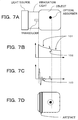
- Fig. 7A shows a schematic diagram of an image information obtaining apparatus which creates images of the interior of an object by PAT
- Fig. 7B shows a sound pressure-time curve of a photoacoustic wave arriving at the transducer shown in Fig. 7A
- Fig. 7C shows a reception signal-time curve detected by the transducer
- Fig. 7D shows a photoacoustic image.
- the portion indicated by 101 in Fig. 7B is the signal amplitude caused by the photoacoustic wave occurring due to light absorption by the object, and is principally constituted by a low frequency component.
- the photoacoustic wave signal produced by light absorption in the object rises in the vicinity of the surface of the object, then in the present invention, the photoacoustic wave occurring due to absorption of light by the object is called a surface photoacoustic wave.
- the portion 102 is the signal amplitude caused by the photoacoustic wave produced by a locally situated optical absorber inside the object such as a tumor, and is principally constituted by a high frequency component. Since a sound pressure-time waveform is detected by a transducer of limited bandwidth having low sensitivity at low frequency, then a reception signal-time waveform such as that shown in Fig. 7C is obtained.
- the portion 103 in Fig. 7C is the transient response (signal amplitude) which occurs when the surface acoustic wave is detected by a transducer of limited bandwidth.
- the signal amplitude caused by the surface photoacoustic wave appears as an artifact such as that shown in Fig. 7D. Therefore, if an optical absorber, such as a tumor, is present nearer to the transducer side than the example shown in Fig. 7A, then the signal amplitude 102 caused by the photoacoustic wave produced by the optical absorber is concealed by the signal amplitude 103 caused by the surface photoacoustic wave. As a result of this, there is a problem in that an image of an optical absorber, such as a tumor, is concealed in the artifact, when imaging is performed.
- a holding plate is provided in an image information obtaining apparatus which uses a photoacoustic effect.
- the holding plate is a mechanism which fixes an object on the apparatus. The purpose of providing this mechanism is to prevent movement of the object and change in the measurement position during measurement, and to enable imaging in a deep part of the object by making the object thinner by compression.
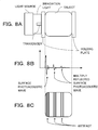
- Fig. 8A shows a schematic drawing of an image information obtaining apparatus of this kind;
- Fig. 8B shows a reception signal-time waveform and
- Fig. 8C shows a photoacoustic image.
- a multiply reflected surface photoacoustic wave is detected by the transducer, due to multiple reflection inside the holding plate.
- a waveform corresponding to 101 in Fig. 7 is reflected by the light source side surface of the holding plate, and is then reflected again by the object side surface, and detected by the transducer.
- a transient response similar to that described above is produced. This is the signal amplitude caused by the multiply reflected surface photoacoustic wave and is detected as shown in Fig. 8B.
- a photoacoustic image is acquired using the reception signal including the multiply reflected surface photoacoustic wave, then an image such as that shown in Fig. 8C is obtained, and similarly to the case of the surface photoacoustic wave, there is a problem in that an image of a tumor, or the like, is concealed by an artifact produced by the multiply reflected surface photoacoustic wave.
- Another issue similar to that of a surface photoacoustic wave described above in an image information obtaining apparatus using a photoacoustic effect is the appearance of artifacts in an ultrasound diagnostic apparatus. More specifically, multiple reflection of the transmitted ultrasound wave is repeated at intermediate objects between the transducer and the object, for example, the acoustic window, the object compression plate, or the like, and this manifests itself as multiple echo artifacts in the image.
- Patent Literature 1 A technique for reducing artifacts caused by multiple reflection of this kind in an ultrasound echo method is disclosed in Patent Literature 1.
- a reference acoustic signal including a multiply reflected ultrasound wave is previously acquired by measurement using a phantom (artificial living organism), and the reference acoustic signal is then subtracted from the signal obtained by measuring the object.
- Patent Literature 2 discloses a method for removing multiple echo produced by an acoustic window constituting an ultrasound diagnostic apparatus.
- multiple echo extracted by averaging a plurality of reception signals that have been received is subtracted from the reception signals so as to remove the multiple echo.
- Patent Literature 3 discloses a method for removing a multiply reflected image produced by a plate for compressing an object, which forms part of a medical imaging apparatus that displays an ultrasound diagnostic image.
- image data representing a plurality of ultrasound images is generated and a multiply reflected image is extracted from the generated image data.
- a multiply reflected image is removed by subtracting an extracted multiply reflected image from the image data of the object.
- a reference acoustic signal including a multiply reflected ultrasonic wave is previously acquired by measurement using a phantom, and the reference acoustic signal is then subtracted from the signal obtained by measuring the object.
- the phantom used to acquire this reference acoustic signal is disclosed as follows. More specifically, the phantom is made of a uniform substance having a surface layer with an acoustic impedance similar to that of living skin (1.5 to 1.6*10 6 kg/m 2 sec), and having an interior with an acoustic impedance similar to that to the surface of living skin, whereby there are no acoustic impedance reflections.
- photoacoustic waves are detected at a plurality of different positions.
- the measurement time can be shortened, and therefore it is common to use an array transducer in which a plurality of elements are aligned.
- Light is irradiated so as to illuminate an object region on the front surface of the array transducer.
- the irradiated light generally has a spatial intensity distribution.
- the amplitude of the photoacoustic wave produced by the photoacoustic effect is directly proportional to the light intensity distribution. Therefore, the surface photoacoustic wave has a spatial sound pressure distribution which is proportional to the spatial intensity distribution of the light irradiated onto the surface of the object. Similarly, the multiply reflected surface photoacoustic wave has a spatial sound pressure distribution. Spatial sound pressure distribution of this kind is a particular feature of an image information obtaining apparatus based on a photoacoustic effect, which generates and detects photoacoustic waves by using light having a spatial intensity distribution.
- the array transducer detects a surface photoacoustic wave having the spatial sound pressure distribution described above, and therefore the amplitude of the surface photoacoustic wave detected by each of the elements constituting the transducer is respectively different. Therefore, when using the method described in Patent Literature 2, a plurality of reception signals having different amplitudes are averaged, and therefore the amplitude of the multiple echo which is extracted does not necessarily coincide with the amplitude of the multiple echo in the reception signals. Therefore, it is difficult to subtract the multiple echo adequately.
- the method described in Patent Literature 2 has beneficial effects in an ultrasound diagnostic apparatus in which the amplitude of the detected multiple echo is uniform, but has a problem in that sufficient beneficial effects are difficult to achieve in application to an image information obtaining apparatus using a photoacoustic effect which has a spatial sound pressure distribution.
- the method described in Patent Literature 3 requires image data which represents a plurality of ultrasound images, and therefore it is necessary to make a plurality of measurements. Hence, there is a problem in that the measurement time is long.
- Patent Literature described above relates to an ultrasound echo apparatus.
- a reflected ultrasonic wave produced when an ultrasonic pulse emitted from the ultrasonic wave oscillator in a probe is reflected once by the surface of a member constituting the apparatus can be distinguished from the echo produced by the object which is under measurement, and therefore does not form noise. Only a multiply reflected ultrasonic wave which has been reflected two or more times has a possibility of being superimposed on the echo produced by the object under measurement, and thus forming noise.
- the present invention was devised in view of these circumstances, an object thereof being to provide an image information obtaining apparatus which is capable of obtaining photoacoustic image data having reduced artifacts.
- This invention provides an image information obtaining apparatus, comprising: a light source; a transducer which detects an acoustic wave and converts the acoustic wave to an electrical signal; a signal processing unit which generates image data, using the electrical signal; a memory unit which stores a reference acoustic signal produced by the transducer detecting an acoustic wave generated when light is irradiated from the light source onto a phantom having acoustic parameters and optical parameters substantially the same as an object and converting the acoustic wave to an electrical signal, wherein the transducer produces an object acoustic signal by converting the acoustic wave, generated when light is irradiated onto an object from the light source, to an electrical signal, and the signal processing unit subtracts the reference acoustic signal from the object acoustic signal and generates image data from the signal resulting from this subtraction.
- This invention also provides an image information obtaining apparatus, comprising: a light source; a transducer which detects an acoustic wave and converts the acoustic wave to an electrical signal; a signal processing unit which generates image data, using the electrical signal; a memory unit which stores image data generated by the signal processing unit from a reference acoustic signal produced by the transducer detecting an acoustic wave generated when light is irradiated from the light source onto a phantom having acoustic parameters and optical parameters substantially the same as an object, and converting the acoustic wave to an electrical signal, wherein the transducer produces an object acoustic signal by converting the acoustic wave, generated when light is irradiated onto an object from the light source, to an electrical signal; and the signal processing unit generates image data from the object acoustic signal, and subtracts image data generated from the reference acoustic signal, from the image data generated from the object acoustic signal.
- This invention also provides a control method for an image information obtaining apparatus having: a light source; a transducer which detects an acoustic wave and converts the acoustic wave to an electrical signal; a memory unit; and a signal processing unit which generates image data, the control method comprising: a step of irradiating light from the light source onto a phantom having acoustic parameters and optical parameters substantially the same as an object; a step of detecting by the transducer detects an acoustic wave generated from the phantom which has absorbed light, and converting the acoustic wave to an electrical signal, and moreover storing the electrical signal in the memory unit as a reference acoustic signal; a step of irradiating light onto an object from a light source; a step of detecting by the transducer an acoustic wave generated from the object which has absorbed light, and converting the acoustic wave to an electrical signal, and moreover storing the electrical signal
- This invention also provides a control method for an image information obtaining apparatus having: a light source; a transducer which detects an acoustic wave and converts the acoustic wave to an electrical signal; a memory unit; and a signal processing unit which generates image data, the control method comprising: a step of irradiating light from the light source onto a phantom having acoustic parameters and optical parameters substantially the same as an object; a step of producing by the transducer a reference acoustic signal by detecting an acoustic wave generated from the phantom which has absorbed light and converting the acoustic wave to an electrical signal; a step generating by the signal processing unit image data from the reference acoustic signal; a step of storing the image data generated from the reference acoustic signal in the memory unit; a step of irradiating light onto an object from a light source; a step of producing by the transducer an object acoustic signal by
- Figs. 1A and 1B are schematic drawings for describing the composition of an image information obtaining apparatus according to Example 1 of the present invention
- Fig. 2 is a diagram showing absorption spectra of HbO 2 and Hb
- Figs. 3A to 3C are diagrams showing various acoustic signal according to Example 1
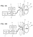
- Figs. 4A and 4B are schematic drawings for describing a modification example of an image information obtaining apparatus according to Example 1
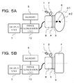
- Figs. 5A and 5B are schematic drawings for describing the composition of an image information obtaining apparatus according to Example 3 of the present invention
- Figs. 6A to 6C are diagrams showing various images according to Example 3
- Figs. 7A to 7D are schematic drawings for describing the formation of artifacts
- Figs. 8A to 8C are schematic drawings of an image information obtaining apparatus having a holding plate.
- Example 1 an example of the composition of the image information obtaining apparatus to which the present invention is applied will be described.
- Fig. 1A shows a schematic diagram illustrating the composition of the image information obtaining apparatus according to the present example.
- the image information obtaining apparatus in Fig. 1A comprises a light source 1, an optical system 2, a transducer 3, an acoustic matching member 4, a memory 5, a signal processing unit 6, an output unit 7 and an acoustic wave detection probe 11.
- E denotes an object of inspection.
- the object E is living tissue, such as a breast, for example.
- the object E includes internal tissue a1 and a2. It is possible to envisage that the internal tissue is an optical absorber, such as a tumor, for example.
- Light source 1 is a light source which emits nanosecond order pulse light of a specific wavelength that is irradiated onto the object E.
- the wavelength of the light emitted by the light source 1 is set to a wavelength corresponding to the absorption spectra of the water, fat, protein, oxygenated hemoglobin, reduced hemoglobin, and the like, which constitute the living tissue.
- an appropriate wavelength range is 600 to 1500 nm, where the spectra of fats, oxygenated hemoglobin and reduced hemoglobin show characteristic features.
- Fig. 2 shows absorption spectra of HbO 2 and Hb in the wavelength range of 600 to 1000 nm.
- the concentration of Hb and HbO 2 contained in the blood inside the living tissue is measured from the absorption spectra of Hb and HbO 2 at a plurality of wavelengths.
- the concentrations of Hb and HbO 2 are measured at a plurality of positions and image data of a concentration distribution is created, thereby making it possible to distinguish a region where new blood vessels have been formed in the living tissue.
- Spectral information relating to Hb and HbO 2 which has been measured by an image information obtaining apparatus in this way can be used for diagnostic purposes.
- Suitable specific examples of the light source 1 are a semiconductor laser which produces different wavelengths, or a variable wavelength laser, or the like.
- the optical system 2 is set so as to guide the liquid emitted from the liquid source 1, to the object E.
- the optical system 2 is constituted by an optical fiber and a lens.
- the light emitted from the light source 1 is expanded by the optical system 2, passed through an acoustic matching member 4, and guided to the surface of the object E.
- An irradiation apparatus is formed by the light source 1 and the optical system 2.
- the acoustic wave detection probe 11 is constituted by a transducer 3 having a piezoelectric effect which converts pressure change caused by a received acoustic wave to an electrical signal, and an acoustic matching member 4.
- the signal obtained by converting an acoustic wave produced by a photoacoustic effect into an electric signal by means of a transducer 3, is taken as an acoustic signal.
- the transducer 3 may be an array type of transducer including an alignment of a plurality of elements which receive an acoustic wave and convert the acoustic wave to an electrical signal.
- the transducer 3 it is appropriate to use a material suited to detection of acoustic waves of 0.5 MHz to several 10 MHz produced by an optical absorber no more than several mm in size, due to a photoacoustic effect. More specifically, it is possible to use a piezoelectric ceramic material, typically PZT (lead zirconate titanate), or a polymer piezoelectric material, typically PVDF (polyvinylidene fluoride), or the like. Furthermore, elements other than piezoelectric elements may be used. For example, it is possible to use a transducer in which elements of an electrostatic capacitance type, such as CMUT (Capacitive Micromachined Ultrasonic Transducers), or the like, are arranged.
- CMUT Capacitive Micromachined Ultrasonic Transducers
- an acoustic matching member 4 which is made of a material having an intermediate acoustic impedance between that of the object E and the transducer 3 and which has a thickness set to 1/4 of the wavelength of the acoustic wave is provided.
- the material constituting the acoustic matching member 4 are epoxy resin, quartz glass, urethane rubber, and the like. It is also possible to envisage a composition where an acoustic matching member is not disposed, and a composition in which the acoustic matching member is integrated with a transducer (or a probe including a transducer).
- the memory 5 is a memory unit that stores a reference acoustic signal, which is described hereinafter.
- a data recording apparatus such as an optical disk, a magnetic disk, a semiconductor memory, a hard disk, or the like.
- the signal processing unit 6 is connected to the transducer 3, the memory 5 and the output unit 7.
- the signal processing unit 6 has a function for subtracting a reference acoustic signal previously stored in the memory 5, from an object acoustic signal obtained by measuring the object E.
- the signal processing unit 6 also has a function for generating image data for displaying the signal processing results on the output unit 7.
- the output unit 7 is a display for displaying the signal processing results from the signal processing unit 6. It is possible to use a display device, such as a liquid crystal display, a CRT, an organic EL display, or the like, for the output unit 7.
- Fig. 1B shows a schematic diagram of the acquisition of a reference acoustic signal.
- a phantom F is provided instead of the object E in Fig. 1A.
- the other constituent elements are the same as in Fig. 1A, and description thereof is omitted here.
- the phantom F has an acoustic impedance (acoustic parameter), and optical absorption properties and optical scattering properties (optical parameters) which are substantially equal to those of the object E.
- the phantom F may be regarded as an artificial living organism which simulates an object.
- the acoustic impedance should be set to 1.5 to 1.6*10 6 kg/m 2 sec.
- the optical absorption properties and the optical scattering properties are set to different values depending on the wavelength of the light emitted by the light source 1. It is possible to use a commonly known material in respect of the optical absorption properties and the optical scattering properties of skin. For example, for light in the wavelength range of no less than 700 nm and no more than 1100 nm, the light scattering coefficient should be set to no less than 0.45 mm -1 and no more than 2.8 mm -1 , and the light absorption coefficient should be set to be no less than 0.001 mm -1 and no more than 0.03 mm -1 .
- the light scattering coefficient is no less than 0.45 mm -1 and no more than 1.2 mm -1 , and if the light absorption coefficient is no less than 0.005 mm -1 and no more than 0.015 mm -1 , since optical characteristics closer to those of a living organism are obtained.
- the typical light absorption coefficient ma of breast tissue at a wavelength of 1064 nm is 0.01 mm -1 and the light scattering coefficient ms' is 0.9 mm -1 , then values close to these should be set.
- pulse light emitted from the light source 1 is expanded by the optical system 2 and guided to the surface of the phantom F.
- the light arriving at the phantom F is scattered at the surface and the interior of the phantom F.
- a portion of the scattered light is reflected by the probe, transmitted by the acoustic matching member 4 again, and then arrives at the surface of the transducer 3 which is in contact with the acoustic matching member 4.
- surface photoacoustic waves based on the respective optical absorption properties are generated by a photoacoustic effect at the phantom F, the acoustic matching member 4, and the surface of the transducer 3, where the light reaches. Furthermore, when these surface photoacoustic waves propagate, they are reflected at the respective surfaces of the phantom F, the acoustic matching member 4 and the transducer 3, and multiply reflected surface photoacoustic waves is generated.
- acoustic waves are detected by the transducer 3 and are converted to an acoustic signal which is an electrical signal.
- the reference acoustic signal is an acoustic signal obtained when the phantom F is measured.
- the result acquired for the reference acoustic signal is sent to the signal processing unit 6 connected to the transducer 3, and is stored in the memory 5 by the signal processing unit 6 and also displayed on the output unit 7.
- Fig. 3A shows a reference acoustic signal which is displayed on the output unit 7 when a phantom is measured by the method described above.
- the horizontal axis indicates time t
- the vertical axis indicates the pressure converted from the acoustic signal.
- T-0 is the signal amplitude due to the surface photoacoustic wave produced by a photoacoustic effect at the contact surface between the transducer 3 and the acoustic matching member 4 when pulse light is irradiated.
- F-0 is the signal amplitude due to the acoustic wave which arrives at the transducer 3 when a surface photoacoustic wave is generated by a photoacoustic effect at the contact surface between the acoustic matching member 4 and the phantom F when pulse light is irradiated, and the surface photoacoustic wave propagates through the acoustic matching member 4.
- T-1 is the signal amplitude due to a multiply reflected surface photoacoustic wave which arrives at the transducer 3 after the surface photoacoustic wave T-0 has propagated through the acoustic matching member 4 and has been reflected once at the interface between the acoustic matching member 4 and the phantom F.
- T-2 is a signal amplitude due to a multiply reflected surface photoacoustic wave which arrives at the transducer 3 after the acoustic wave at T-1 has been reflected once at the interface between the transducer 3 and the acoustic matching member 4, has propagated in the acoustic matching member 4, and has been reflected a second time at the interface between the acoustic matching member 4 and the phantom F.
- T-3, T-4, and so on are signal amplitudes due to multiply reflected surface photoacoustic waves.
- F-1 is a signal amplitude of a multiply reflected surface photoacoustic wave which arrives at the transducer 3 after the surface photoacoustic wave at F-0 has been reflected once at the interface between the transducer 3 and the acoustic matching member 4, has propagated in the acoustic matching member 4, and has been reflected a first time at the interface between the acoustic matching member 4 and the phantom F.
- F-2 is a signal amplitude of a multiply reflected surface photoacoustic wave which arrives at the transducer 3 after the acoustic wave at F-1 has been reflected a second time at the interface between the transducer 3 and the acoustic matching member 4, has propagated in the acoustic matching member 4, and has been reflected a second time at the interface between the acoustic matching member 4 and the phantom F.
- F-3, F-4, and so on are signal amplitudes due to multiply reflected surface photoacoustic waves.
- pulse light emitted from the light source 1 is expanded by the optical system 2, transmitted through the acoustic matching member 4 and guided to the surface of the object E.
- the light arriving at the object E is scattered by the surface and the interior of the object E.
- a portion of the scattered light is reflected by the probe, transmitted by the acoustic matching member 4 again, and then arrives at the surface of the transducer 3 which is in contact with the acoustic matching member 4.
- an acoustic wave based on the optical absorption properties of the internal tissue is produced by a photoacoustic effect inside the object E.
- surface photoacoustic waves based on the respective optical absorption properties are generated by a photoacoustic effect at the object E, the acoustic matching member 4, and the surface of the transducer 3, where the light reaches.
- these surface photoacoustic waves propagates, they are reflected at the respective surfaces of the object E, the acoustic matching member 4 and the transducer 3, and multiply reflected surface photoacoustic waves are generated.
- the transducer 3 These acoustic waves are detected by the transducer 3 and are converted to an acoustic signal which is an electrical signal.
- the object acoustic signal is an acoustic signal obtained when the object E is measured.
- the result acquired for the object acoustic signal is sent to the signal processing unit 6 connected to the transducer 3, and is stored in the memory 5 by the signal processing unit 6.
- Fig. 3B shows an object acoustic signal stored in the memory 5.
- T-0 is the signal amplitude of a surface photoacoustic wave at the contact surface between the transducer 3 and the acoustic matching member 4, similarly to that shown in Fig. 3A.
- E-0 is the signal amplitude of the acoustic wave which arrives at the transducer 3 when a surface photoacoustic wave is generated by a photoacoustic effect at the contact surface between the acoustic matching member 4 and the object E when pulse light is irradiated, and the surface photoacoustic wave propagates through the acoustic matching member 4.
- the acoustic waves generated after F-0 are a synthesis of an acoustic wave generated by a photoacoustic effect in the internal tissue of the object E and the multiply reflected surface photoacoustic waves T-1, T-2, ..., F-1, F-2, ..., described in Fig. 3A.
- the signal processing unit 6 is an apparatus which subtracts a reference acoustic signal previously stored in the memory 5 from the object acoustic signal, and generates image data using the signal resulting from this subtraction (differential acoustic signal).
- the output unit 7 displays this image data. Furthermore, it can also display the differential acoustic signal before it is converted into image data.
- Fig. 3C shows a differential acoustic signal obtained by subtracting the reference acoustic signal from the object acoustic signal displayed on the output unit 7.
- the N-shaped waveforms a-1 and a-2 shown in Fig. 3C represent a state where artifacts have been reduced in the signals from the internal tissue a1 and a2 of the object E shown in Fig. 1A.
- the image information obtaining apparatus it is possible to reduce the effects of surface photoacoustic waves and multiply reflected surface photoacoustic waves, by subtracting a reference acoustic signal from the object acoustic signal.
- a reference acoustic signal By using an acoustic signal of this kind, it is possible to obtain photoacoustic image data having reduced artifacts.
- Figs. 4A and 4B show modification examples of an image information obtaining apparatus according to the present example.
- the description centers on the constituent elements which differ from Fig. 1.
- a second acoustic matching member 12 for holding an object E is provided between the acoustic matching member 4 and the object E.
- the second acoustic matching member 12 is a flat plate which holds the object E by making contact with the object E, and furthermore, the second acoustic matching member 12 has high transmissivity and low attenuation with respect to acoustic waves generated by a photoacoustic effect, and high transmissivity and low attenuation with respect to light emitted by the light source 1.
- Examples of the material constituting the acoustic matching member 4 are quartz glass, polymethyl pentene polymer, polycarbonate, acrylic, or the like.
- a third acoustic matching member 13 is provided in a gap between the acoustic matching member 4 and the second acoustic matching member 12.
- the third acoustic matching member 13 is provided for the purpose of acoustic impedance matching between the acoustic matching member 4 and the second acoustic matching member 12.
- the third acoustic matching member 13 has high transmissivity and low attenuation with respect to acoustic waves produced by the photoacoustic effect and high transmissivity and low attenuation with respect to light emitted by the light source 1.
- a holding member and matching agent are added, as shown in Fig. 4A and Fig. 4B, it is still possible to remove the effects of surface photoacoustic waves and multiply reflected surface photoacoustic waves by means of a similar method to that described above.
- a reference signal including the effects of surface photoacoustic waves produced at the surface of the holding member and the matching agent is obtained, saved in a memory and used for signal processing.
- an acoustic signal of this kind it is possible to obtain photoacoustic image data having reduced artifacts.
- Example 2 relates to the composition of an image information obtaining apparatus which is able to correct for disparities caused by these individual differences by using a phantom F having average values for the optical absorption properties and the optical scattering properties.
- Example 2 a reference acoustic signal of the phantom F shown in Fig. 3A is obtained.
- the signal intensity of the surface photoacoustic wave at F-0 is AF0
- the signal intensity of the acoustic wave at F-1 is AF1
- the signal intensity of the acoustic wave at F-2 is AF2.
- an object acoustic signal for the object E shown in Fig. 3B is acquired.
- the signal intensity of the surface photoacoustic wave at E-0 is AE0.
- E-0 is a surface photoacoustic wave generated by a photoacoustic effect at the contact surface between the acoustic matching member 4 and the object E, and therefore if AF0 and AE0 are equal when compared with each other, the optical absorption properties and the optical scattering properties of the phantom F and the object E are the same.
- it is possible to correct differences in the optical absorption properties and the optical scattering properties of the phantom F and the object E by correcting the signal intensity AF0 of the reference acoustic signal at F-0 to the intensity AE0.
- AF1 shown in Fig. 3A is corrected to AF1*(AE0/AF0), and AF2 is corrected to AF2*(AE0/AF0).
- values are corrected to AF3*(AE0/AF0), AF4*(AE0/AF0), and so on.
- the signal processing unit 6 generates the corrected reference acoustic signal described above and stores this corrected reference acoustic signal in the memory 5. In this way, the signal processing unit 6 functions as a corrected acoustic signal generation unit for generating a corrected reference acoustic signal.
- the signal processing unit 6 generates image data using a differential acoustic signal obtained by subtracting the corrected reference acoustic signal stored previously in the memory 5 from the object acoustic signal.
- the output unit 6 displays this image data, as an image.
- the object acoustic signal and the reference acoustic signal are compared and a coefficient for use in correction is determined.
- a coefficient for use in correction is determined.
- FIG. 5A An example of the composition of an image information obtaining apparatus which removes the effects of multiply reflected surface photoacoustic waves using cross-sectional image data is now described with reference to Fig. 5A.
- the constituent members labeled with the same reference numbers in Fig. 1A have the same function as those described above.
- the apparatus shown in Fig. 5A includes a one dimensional array transducer 8, an acoustic lens 9, and an image generation unit 10.
- the one dimensional array transducer 8 is formed by a one dimensional arrangement of piezoelectric elements which were described with respect to the transducer 3.
- a signal for a desired position is obtained by a Sum And Delay Beamforming method, from the plurality of acoustic signals obtained from the plurality of piezoelectric elements.
- the acoustic lens 9 has a focal distance inside the object E, and high transmissivity and low permittivity with respect to acoustic waves produced by a photoacoustic effect, similarly to the acoustic matching member 4.
- the material constituting an acoustic lens is desirably a material having an intermediate acoustic impedance between the object E and the piezoelectric elements, for example, a silicone rubber or polymer resin material, or the like.
- the acoustic lens is made of a material in which the speed of sound is slower than the speed of sound in the object E, then the lens has a convex shape, and the focal distance is determined by the curvature of the convex surface, while the focal size and focal depth are determined by the focal distance and the lens diameter.
- an acoustic lens is used, but it is also possible to use piezoelectric elements having a concave surface.
- piezoelectric elements having a concave surface.
- electrostatic capacitance type of element or the like.
- the image generation unit 10 is a signal processing unit having a function of generating two dimensional cross-sectional image data from an acoustic signal.
- the image generation unit 10 stores generated data in the memory 5, similarly to the signal processing unit 6 described in Example 1. Furthermore, the image generation unit 10 also has a function of subtracting reference image data from the object image data described below.
- Fig. 5B shows the acquisition of reference image data.
- a phantom F is provided instead of the object E in Fig. 5A.
- the phantom F may use a phantom similar to that described in relation to Example 1.
- pulse light emitted from the light source 1 is expanded by the optical system 2 and guided to the surface of the phantom F from the vicinity of the side face of the acoustic lens 9.
- the light arriving at the phantom F is scattered at the surface and the interior of the phantom F. A portion of the scattered light is reflected by the probe and arrives at the acoustic lens 9 and the one dimensional array transducer 8.
- surface photoacoustic waves based on the respective optical absorption properties are generated by a photoacoustic effect at the phantom F, the acoustic lens 9, and the surface of the one dimensional array transducer 8, where the light reaches. Furthermore, when these surface photoacoustic wave propagate, they are reflected at the respective surfaces of the phantom F, the acoustic lens 9 and the one dimensional array transducer 8, and multiply reflected surface photoacoustic waves are generated. These acoustic waves are detected by the one dimensional array transducer 8 and are converted to an acoustic signal which is an electrical signal.
- the acoustic signal is supplied to the image generation unit 10 connected to the one dimensional array transducer 8, and two dimensional cross-sectional image data is generated by the image generation unit 10.
- the image data obtained by measuring the phantom F is taken as reference image data.
- the reference image data is stored in the memory 5 by the image generation unit 10.
- Fig. 6A is a reference image displayed on the output unit 7.
- the stripe pattern Ti-0 in Fig. 6A is an image produced by a surface photoacoustic wave generated by a photoacoustic effect at the contact surface between the one-dimensional array transducer 8 and the acoustic lens 9 when pulse light is irradiated.
- no consideration is given to the thickness of the acoustic matching member 4, but if a surface photoacoustic wave occurs at the surface of the acoustic matching member, then this can be handled similarly to other contact surfaces.
- the stripe pattern Fi-0 is an image due to the acoustic wave which arrives at the one-dimensional array transducer 8 when a surface photoacoustic wave is generated by a photoacoustic effect at the contact surface between the acoustic lens 9 and the phantom F when pulse light is irradiated, and the surface photoacoustic wave propagates through the acoustic lens 9.
- the stripe pattern Ti-1 is an image due to a multiply reflected surface photoacoustic wave which arrives at the transducer 3 after the surface photoacoustic wave at Ti-0 has propagated through the acoustic lens 9 and has been reflected once at the interface between the acoustic matching member 9 and the phantom F.
- the stripe pattern Ti-2 is an image produced by a multiply reflected surface photoacoustic wave.
- an acoustic wave at Ti-1 propagates through the acoustic lens 9 after being reflected once at the interface between the one dimensional array transducer 8 and the acoustic lens 9, and then reaches the one dimensional array transducer 8 after being reflected for a second time at the interface between the acoustic lens 9 and the phantom F.
- the stripe pattern Fi-1 is an image produced by a multiply reflected surface photoacoustic wave. More specifically, a surface photoacoustic wave at Fi-0 propagates through the acoustic lens 9 after being reflected once at the interface between the one dimensional array transducer 8 and the acoustic lens 9, and then reaches the one dimensional array transducer 8 after being reflected for a first time at the interface between the acoustic lens 9 and the phantom F.
- the stripe pattern Fi-2 is an image produced by a multiply reflected surface photoacoustic wave. More specifically, the surface photoacoustic wave at Fi-1 propagates through the acoustic lens 9 after being reflected for a second time at the interface between the one dimensional array transducer 8 and the acoustic lens 9, and then reaches the one dimensional array transducer 8 after being reflected for a second time at the interface between the acoustic lens 9 and the phantom F. Although not shown in the drawings, thereafter, there are also images Fi-3, Fi-4, and so on, due to multiply reflected surface photoacoustic waves.
- pulse light emitted from the light source 1 is expanded by the optical system 2 and guided to the surface of the object E from the vicinity of the side face of the acoustic lens 9.
- the light arriving at the object E is scattered by the surface and the interior of the object E.
- a portion of the scattered light is reflected by the probe and arrives at the acoustic lens 9 and the one dimensional array transducer 8.
- an acoustic wave based on the optical absorption properties of the internal tissue is produced by a photoacoustic effect inside the object E.
- surface photoacoustic waves based on the respective optical absorption properties are generated by a photoacoustic effect at the object E, the acoustic lens 9, and the surface of the one dimensional array transducer 8, where the light reaches.
- these surface photoacoustic waves propagate, they are reflected at the respective surfaces of the object E, the acoustic lens 9 and the one dimensional array transducer 8, and multiply reflected surface photoacoustic waves are generated.
- acoustic waves are detected by the one dimensional array transducer 8 and are converted to an acoustic signal which is an electrical signal.
- the acoustic signal is supplied to the image generation unit 10 connected to the one dimensional array transducer 8, and two dimensional cross-sectional image data is generated by the image generation unit 10.
- the image data obtained by measuring the object E is taken as object image data.
- the object image data is stored in the memory 5 by the image generation unit 10.
- Fig. 6B is an object image displayed on the output unit 7.
- the stripe pattern Ti-0 is an example of imaging using the composition shown in Fig. 5A.
- the stripe pattern Ei-0 is an image due to the acoustic wave which arrives at the one dimensional array transducer 8, when a surface photoacoustic wave is generated by a photoacoustic effect at the contact surface between the acoustic lens 9 and the object E when pulse light is irradiated, and the surface photoacoustic wave propagates through the acoustic lens 9.
- the stripe patterns apart from the stripe patterns Ti-0 and Ei-0 are a synthesis of an acoustic wave produced by a photoacoustic effect in the internal tissue of the object E and the images Ti-1, Ti-2, ..., Fi-1, Fi-2, ..., caused by multiply reflected surface photoacoustic waves illustrated in Fig. 5A.
- the image generation unit 10 which forms the signal processing unit outputs the result of subtracting the reference image data previously stored in the memory 5 from the object acoustic image data (differential image data), to the output unit 7, and the output unit 7 displays the differential image.
- Fig. 6C is a differential image obtained by subtracting reference image data from object image data, which is displayed on the output unit 7.
- ai-1 indicates an acoustic wave from internal tissue a1 of the object E shown in Fig. 5A and ai-2 indicates an acoustic wave from internal tissue a2.
- the image information obtaining apparatus it is possible to reduce the effects of surface photoacoustic waves and multiply reflected surface photoacoustic waves, by subtracting reference image data from the object image data.
- an acoustic signal of this kind it is possible to obtain photoacoustic image data having reduced artifacts.
- cross-sectional image data is obtained by using a one dimensional array transducer, but it is also possible to obtain cross-sectional image data by performing a scanning action with a single element transducer. Moreover, it is also possible to use the present invention in cases where three dimensional image data is obtained by performing a scanning action of a transducer or a two dimensional array transducer.
Abstract
An image information obtaining apparatus having: a light source; a transducer which detects an acoustic wave and converts the acoustic wave to an electrical signal; a signal processing unit which generates image data, using the electrical signal; and a memory unit which stores a reference acoustic signal produced by the transducer detecting an acoustic wave generated when light is irradiated from the light source onto a phantom having acoustic parameters and optical parameters substantially the same as an object and converting the acoustic wave to an electrical signal, wherein the transducer produces an object acoustic signal by converting the acoustic wave, generated when light is irradiated onto an object from the light source, to an electrical signal; and the signal processing unit subtracts the reference acoustic signal from the object acoustic signal and generates image data from the signal resulting from this subtraction.
Description
The present invention relates to an image information obtaining apparatus and a control method for same.
In the field of medicine, there has been active research into optical imaging apparatuses which irradiate light onto a living organism, which is an object under inspection, from a light source, such as a laser, and create an image of information inside the living organism obtained on the basis of the incident light. One example of optical imaging technology of this kind is Photoacoustic Tomography (PAT). In PAT, pulse light generated from a light source is irradiated onto a living organism, and the living tissue absorbs the pulse light which propagates and diffuses inside the organism and generates an acoustic wave (typically, an ultrasound wave), which is detected. The mechanism producing this photoacoustic wave is called the photoacoustic effect. An acoustic wave generated by the photoacoustic effect is called a photoacoustic wave.
A site under inspection, such as tumor, often has a higher light energy absorption rate compared to the surrounding tissue, and therefore absorbs a larger amount of light than the surrounding tissue and swells momentarily. The acoustic wave generated by this swelling action is detected by a transducer to obtain a reception signal. By mathematically analyzing the reception signal, it is possible to create an image of the acoustic pressure distribution of the photoacoustic wave produced by the photoacoustic effect inside the object. On the basis of photoacoustic image data obtained in this way, it is possible to obtain a distribution of optical characteristics, and in particular, a distribution of the absorption coefficient, inside the living organism. This information can be used for quantitative measurement of specific substances in the object, for example, glucose or hemoglobin contained in blood. In recent years, in use of the PAT, preclinical research which creates images of blood vessels of small animals, and clinical research which applies this principle to diagnosis of breast cancer, and the like, has been pursued actively.
Fig. 7A shows a schematic diagram of an image information obtaining apparatus which creates images of the interior of an object by PAT, and Fig. 7B shows a sound pressure-time curve of a photoacoustic wave arriving at the transducer shown in Fig. 7A. Furthermore, Fig. 7C shows a reception signal-time curve detected by the transducer, and Fig. 7D shows a photoacoustic image. The portion indicated by 101 in Fig. 7B is the signal amplitude caused by the photoacoustic wave occurring due to light absorption by the object, and is principally constituted by a low frequency component. Since the photoacoustic wave signal produced by light absorption in the object rises in the vicinity of the surface of the object, then in the present invention, the photoacoustic wave occurring due to absorption of light by the object is called a surface photoacoustic wave. On the other hand, the portion 102 is the signal amplitude caused by the photoacoustic wave produced by a locally situated optical absorber inside the object such as a tumor, and is principally constituted by a high frequency component. Since a sound pressure-time waveform is detected by a transducer of limited bandwidth having low sensitivity at low frequency, then a reception signal-time waveform such as that shown in Fig. 7C is obtained. The portion 103 in Fig. 7C is the transient response (signal amplitude) which occurs when the surface acoustic wave is detected by a transducer of limited bandwidth.
When the interior of an object is imaged by using the reception signal-time waveform in Fig. 7C and a photoacoustic image is acquired, the signal amplitude caused by the surface photoacoustic wave appears as an artifact such as that shown in Fig. 7D. Therefore, if an optical absorber, such as a tumor, is present nearer to the transducer side than the example shown in Fig. 7A, then the signal amplitude 102 caused by the photoacoustic wave produced by the optical absorber is concealed by the signal amplitude 103 caused by the surface photoacoustic wave. As a result of this, there is a problem in that an image of an optical absorber, such as a tumor, is concealed in the artifact, when imaging is performed.
Moreover, there are cases where a holding plate is provided in an image information obtaining apparatus which uses a photoacoustic effect. The holding plate is a mechanism which fixes an object on the apparatus. The purpose of providing this mechanism is to prevent movement of the object and change in the measurement position during measurement, and to enable imaging in a deep part of the object by making the object thinner by compression. Fig. 8A shows a schematic drawing of an image information obtaining apparatus of this kind; Fig. 8B shows a reception signal-time waveform and Fig. 8C shows a photoacoustic image.
If a holding plate is provided as in Fig. 8A, a multiply reflected surface photoacoustic wave is detected by the transducer, due to multiple reflection inside the holding plate. In other words, a waveform corresponding to 101 in Fig. 7 is reflected by the light source side surface of the holding plate, and is then reflected again by the object side surface, and detected by the transducer. In this case, a transient response similar to that described above is produced. This is the signal amplitude caused by the multiply reflected surface photoacoustic wave and is detected as shown in Fig. 8B. If a photoacoustic image is acquired using the reception signal including the multiply reflected surface photoacoustic wave, then an image such as that shown in Fig. 8C is obtained, and similarly to the case of the surface photoacoustic wave, there is a problem in that an image of a tumor, or the like, is concealed by an artifact produced by the multiply reflected surface photoacoustic wave.
Another issue similar to that of a surface photoacoustic wave described above in an image information obtaining apparatus using a photoacoustic effect is the appearance of artifacts in an ultrasound diagnostic apparatus. More specifically, multiple reflection of the transmitted ultrasound wave is repeated at intermediate objects between the transducer and the object, for example, the acoustic window, the object compression plate, or the like, and this manifests itself as multiple echo artifacts in the image.
A technique for reducing artifacts caused by multiple reflection of this kind in an ultrasound echo method is disclosed in Patent Literature 1. In the apparatus described in Patent Literature 1, a reference acoustic signal including a multiply reflected ultrasound wave is previously acquired by measurement using a phantom (artificial living organism), and the reference acoustic signal is then subtracted from the signal obtained by measuring the object.
Furthermore, Patent Literature 2 discloses a method for removing multiple echo produced by an acoustic window constituting an ultrasound diagnostic apparatus. In Patent Literature 2, multiple echo extracted by averaging a plurality of reception signals that have been received is subtracted from the reception signals so as to remove the multiple echo.
Moreover, Patent Literature 3 discloses a method for removing a multiply reflected image produced by a plate for compressing an object, which forms part of a medical imaging apparatus that displays an ultrasound diagnostic image. In Patent Literature 3, image data representing a plurality of ultrasound images is generated and a multiply reflected image is extracted from the generated image data. A multiply reflected image is removed by subtracting an extracted multiply reflected image from the image data of the object.
In the apparatus described in Patent Literature 1, a reference acoustic signal including a multiply reflected ultrasonic wave is previously acquired by measurement using a phantom, and the reference acoustic signal is then subtracted from the signal obtained by measuring the object. The phantom used to acquire this reference acoustic signal is disclosed as follows. More specifically, the phantom is made of a uniform substance having a surface layer with an acoustic impedance similar to that of living skin (1.5 to 1.6*106 kg/m2sec), and having an interior with an acoustic impedance similar to that to the surface of living skin, whereby there are no acoustic impedance reflections.
However, when using a photoacoustic effect, even if the phantom described above is employed, the intensity of the surface photoacoustic wave produced by the phantom described above is different to the surface photoacoustic wave produced by the object and therefore the artifact cannot be removed.
Furthermore, in an image information obtaining apparatus using a photoacoustic effect, photoacoustic waves are detected at a plurality of different positions. By measuring the photoacoustic waves simultaneously in a plurality of different positions, the measurement time can be shortened, and therefore it is common to use an array transducer in which a plurality of elements are aligned. Light is irradiated so as to illuminate an object region on the front surface of the array transducer. In this case, the irradiated light generally has a spatial intensity distribution.
The amplitude of the photoacoustic wave produced by the photoacoustic effect is directly proportional to the light intensity distribution. Therefore, the surface photoacoustic wave has a spatial sound pressure distribution which is proportional to the spatial intensity distribution of the light irradiated onto the surface of the object. Similarly, the multiply reflected surface photoacoustic wave has a spatial sound pressure distribution. Spatial sound pressure distribution of this kind is a particular feature of an image information obtaining apparatus based on a photoacoustic effect, which generates and detects photoacoustic waves by using light having a spatial intensity distribution.
The array transducer detects a surface photoacoustic wave having the spatial sound pressure distribution described above, and therefore the amplitude of the surface photoacoustic wave detected by each of the elements constituting the transducer is respectively different. Therefore, when using the method described in Patent Literature 2, a plurality of reception signals having different amplitudes are averaged, and therefore the amplitude of the multiple echo which is extracted does not necessarily coincide with the amplitude of the multiple echo in the reception signals. Therefore, it is difficult to subtract the multiple echo adequately. More specifically, the method described in Patent Literature 2 has beneficial effects in an ultrasound diagnostic apparatus in which the amplitude of the detected multiple echo is uniform, but has a problem in that sufficient beneficial effects are difficult to achieve in application to an image information obtaining apparatus using a photoacoustic effect which has a spatial sound pressure distribution. Furthermore, the method described in Patent Literature 3 requires image data which represents a plurality of ultrasound images, and therefore it is necessary to make a plurality of measurements. Hence, there is a problem in that the measurement time is long.
Moreover, Patent Literature described above relates to an ultrasound echo apparatus. In an ultrasound echo method, a reflected ultrasonic wave produced when an ultrasonic pulse emitted from the ultrasonic wave oscillator in a probe is reflected once by the surface of a member constituting the apparatus can be distinguished from the echo produced by the object which is under measurement, and therefore does not form noise. Only a multiply reflected ultrasonic wave which has been reflected two or more times has a possibility of being superimposed on the echo produced by the object under measurement, and thus forming noise. In this way, with an ultrasound echo method, only a multiply reflected ultrasonic wave which is reflected two or more times forms noise, whereas an apparatus based on a photoacoustic effect differs from this in that a reflected ultrasonic wave which has been reflected one or more times forms noise.
In this way, the patent literatures described above disclose a method of removing multiply reflected ultrasonic waves in an ultrasound echo method, but as yet there has been no disclosure about surface photoacoustic waves in an apparatus which uses a photoacoustic effect or a method for removing multiply reflected surface photoacoustic waves.
The present invention was devised in view of these circumstances, an object thereof being to provide an image information obtaining apparatus which is capable of obtaining photoacoustic image data having reduced artifacts.
This invention provides an image information obtaining apparatus, comprising:
a light source;
a transducer which detects an acoustic wave and converts the acoustic wave to an electrical signal;
a signal processing unit which generates image data, using the electrical signal;
a memory unit which stores a reference acoustic signal produced by the transducer detecting an acoustic wave generated when light is irradiated from the light source onto a phantom having acoustic parameters and optical parameters substantially the same as an object and converting the acoustic wave to an electrical signal, wherein
the transducer produces an object acoustic signal by converting the acoustic wave, generated when light is irradiated onto an object from the light source, to an electrical signal, and
the signal processing unit subtracts the reference acoustic signal from the object acoustic signal and generates image data from the signal resulting from this subtraction.
This invention also provides an image information obtaining apparatus, comprising:
a light source;
a transducer which detects an acoustic wave and converts the acoustic wave to an electrical signal;
a signal processing unit which generates image data, using the electrical signal;
a memory unit which stores image data generated by the signal processing unit from a reference acoustic signal produced by the transducer detecting an acoustic wave generated when light is irradiated from the light source onto a phantom having acoustic parameters and optical parameters substantially the same as an object, and converting the acoustic wave to an electrical signal, wherein
the transducer produces an object acoustic signal by converting the acoustic wave, generated when light is irradiated onto an object from the light source, to an electrical signal; and
the signal processing unit generates image data from the object acoustic signal, and subtracts image data generated from the reference acoustic signal, from the image data generated from the object acoustic signal.
This invention also provides a control method for an image information obtaining apparatus having: a light source; a transducer which detects an acoustic wave and converts the acoustic wave to an electrical signal; a memory unit; and a signal processing unit which generates image data,
the control method comprising:
a step of irradiating light from the light source onto a phantom having acoustic parameters and optical parameters substantially the same as an object;
a step of detecting by the transducer detects an acoustic wave generated from the phantom which has absorbed light, and converting the acoustic wave to an electrical signal, and moreover storing the electrical signal in the memory unit as a reference acoustic signal;
a step of irradiating light onto an object from a light source;
a step of detecting by the transducer an acoustic wave generated from the object which has absorbed light, and converting the acoustic wave to an electrical signal, and moreover storing the electrical signal in the memory unit as an object acoustic signal; and
a step of subtracting by the signal processing unit the reference acoustic signal from the object acoustic signal and generating image data from the signal resulting from this subtraction.
This invention also provides a control method for an image information obtaining apparatus having: a light source; a transducer which detects an acoustic wave and converts the acoustic wave to an electrical signal; a memory unit; and a signal processing unit which generates image data,
the control method comprising:
a step of irradiating light from the light source onto a phantom having acoustic parameters and optical parameters substantially the same as an object;
a step of producing by the transducer a reference acoustic signal by detecting an acoustic wave generated from the phantom which has absorbed light and converting the acoustic wave to an electrical signal;
a step generating by the signal processing unit image data from the reference acoustic signal;
a step of storing the image data generated from the reference acoustic signal in the memory unit;
a step of irradiating light onto an object from a light source;
a step of producing by the transducer an object acoustic signal by converting an acoustic wave, generated when light is irradiated onto an object from the light source, to an electrical signal;
a step of generating by the signal processing unit image data from the object acoustic signal; and
a step of subtracting by the signal processing unit image data generated from the reference acoustic signal, from image data generated from the object acoustic signal.
According to the present invention, it is possible to provide an image information obtaining apparatus capable of obtaining photoacoustic image data having reduced artifacts.
Further features of the present invention will become apparent from the following description of exemplary embodiments with reference to the attached drawings.
Further features of the present invention will become apparent from the following description of exemplary embodiments with reference to the attached drawings.
A desirable mode for carrying out the present invention is described below with reference to the drawings. The dimensions, materials, shapes and relative positions, and the like, of the constituent parts described below should be changed appropriately depending on the composition and various conditions of the apparatus to which the invention is applied, and it is not intended to limit the scope of the invention to the description given below. Furthermore, the present invention may also be interpreted as a control method by which an information processing apparatus, or the like, controls the image information obtaining apparatus described below.
In Example 1, an example of the composition of the image information obtaining apparatus to which the present invention is applied will be described.
Fig. 1A shows a schematic diagram illustrating the composition of the image information obtaining apparatus according to the present example. The image information obtaining apparatus in Fig. 1A comprises alight source 1, an optical system 2, a transducer 3, an acoustic matching member 4, a memory 5, a signal processing unit 6, an output unit 7 and an acoustic wave detection probe 11. In Fig. 1A, E denotes an object of inspection. The object E is living tissue, such as a breast, for example. The object E includes internal tissue a1 and a2. It is possible to envisage that the internal tissue is an optical absorber, such as a tumor, for example.
Fig. 1A shows a schematic diagram illustrating the composition of the image information obtaining apparatus according to the present example. The image information obtaining apparatus in Fig. 1A comprises a
Below, the details of each constituent element are described.
Light source 1 is a light source which emits nanosecond order pulse light of a specific wavelength that is irradiated onto the object E. The wavelength of the light emitted by the light source 1 is set to a wavelength corresponding to the absorption spectra of the water, fat, protein, oxygenated hemoglobin, reduced hemoglobin, and the like, which constitute the living tissue. For example, since water, which is the main component of internal living tissue, has low absorption, light is transmitted well through the water, and therefore an appropriate wavelength range is 600 to 1500 nm, where the spectra of fats, oxygenated hemoglobin and reduced hemoglobin show characteristic features.
Moreover, it is known that if a cancerous tumor, or the like, grows in living tissue, then new blood vessels form and the consumption of oxygen increases. A method of assessing the formation of new blood vessels and increase in oxygen consumption in this way is to use the characteristic features of the absorption spectra of oxygenated hemoglobin (HbO2) and reduced hemoglobin (Hb). Fig. 2 shows absorption spectra of HbO2 and Hb in the wavelength range of 600 to 1000 nm.
In an image information obtaining apparatus, the concentration of Hb and HbO2 contained in the blood inside the living tissue is measured from the absorption spectra of Hb and HbO2 at a plurality of wavelengths. The concentrations of Hb and HbO2 are measured at a plurality of positions and image data of a concentration distribution is created, thereby making it possible to distinguish a region where new blood vessels have been formed in the living tissue. Furthermore, it is also possible to calculate the oxygen saturation from the concentrations of Hb and HbO2 and to distinguish a region where the oxygen consumption has increased, from the oxygen saturation. Spectral information relating to Hb and HbO2 which has been measured by an image information obtaining apparatus in this way can be used for diagnostic purposes.
Suitable specific examples of the light source 1 are a semiconductor laser which produces different wavelengths, or a variable wavelength laser, or the like. The optical system 2 is set so as to guide the liquid emitted from the liquid source 1, to the object E. The optical system 2 is constituted by an optical fiber and a lens. The light emitted from the light source 1 is expanded by the optical system 2, passed through an acoustic matching member 4, and guided to the surface of the object E. An irradiation apparatus is formed by the light source 1 and the optical system 2.
The acoustic wave detection probe 11 is constituted by a transducer 3 having a piezoelectric effect which converts pressure change caused by a received acoustic wave to an electrical signal, and an acoustic matching member 4. In the present specification, the signal obtained by converting an acoustic wave produced by a photoacoustic effect into an electric signal by means of a transducer 3, is taken as an acoustic signal. The transducer 3 may be an array type of transducer including an alignment of a plurality of elements which receive an acoustic wave and convert the acoustic wave to an electrical signal. It is known that, if the size of a cancerous tumor, or the like, becomes 2 to 3 mm or more, due to the development of the tumor, then the formation of new blood vessels increases. Therefore, for the transducer 3, it is appropriate to use a material suited to detection of acoustic waves of 0.5 MHz to several 10 MHz produced by an optical absorber no more than several mm in size, due to a photoacoustic effect. More specifically, it is possible to use a piezoelectric ceramic material, typically PZT (lead zirconate titanate), or a polymer piezoelectric material, typically PVDF (polyvinylidene fluoride), or the like. Furthermore, elements other than piezoelectric elements may be used. For example, it is possible to use a transducer in which elements of an electrostatic capacitance type, such as CMUT (Capacitive Micromachined Ultrasonic Transducers), or the like, are arranged.
Furthermore, in many cases, there is a large difference in acoustic impedance between the transducer 3 and the object E. In this case, there is greater reflection at the interface where the transducer 3 makes contact with the object E and it is difficult to transmit the acoustic wave generated by the photoacoustic effect efficiently to the transducer 3. Therefore, an acoustic matching member 4 which is made of a material having an intermediate acoustic impedance between that of the object E and the transducer 3 and which has a thickness set to 1/4 of the wavelength of the acoustic wave is provided. Examples of the material constituting the acoustic matching member 4 are epoxy resin, quartz glass, urethane rubber, and the like. It is also possible to envisage a composition where an acoustic matching member is not disposed, and a composition in which the acoustic matching member is integrated with a transducer (or a probe including a transducer).
The memory 5 is a memory unit that stores a reference acoustic signal, which is described hereinafter. For the memory 5, it is possible to use a data recording apparatus, such as an optical disk, a magnetic disk, a semiconductor memory, a hard disk, or the like. The signal processing unit 6 is connected to the transducer 3, the memory 5 and the output unit 7. The signal processing unit 6 has a function for subtracting a reference acoustic signal previously stored in the memory 5, from an object acoustic signal obtained by measuring the object E. Furthermore, the signal processing unit 6 also has a function for generating image data for displaying the signal processing results on the output unit 7. The output unit 7 is a display for displaying the signal processing results from the signal processing unit 6. It is possible to use a display device, such as a liquid crystal display, a CRT, an organic EL display, or the like, for the output unit 7.
Fig. 1B shows a schematic diagram of the acquisition of a reference acoustic signal. A phantom F is provided instead of the object E in Fig. 1A. The other constituent elements are the same as in Fig. 1A, and description thereof is omitted here.
The phantom F has an acoustic impedance (acoustic parameter), and optical absorption properties and optical scattering properties (optical parameters) which are substantially equal to those of the object E. The phantom F may be regarded as an artificial living organism which simulates an object. For example, the acoustic impedance should be set to 1.5 to 1.6*106 kg/m2sec. Furthermore, the optical absorption properties and the optical scattering properties are set to different values depending on the wavelength of the light emitted by thelight source 1. It is possible to use a commonly known material in respect of the optical absorption properties and the optical scattering properties of skin. For example, for light in the wavelength range of no less than 700 nm and no more than 1100 nm, the light scattering coefficient should be set to no less than 0.45 mm-1 and no more than 2.8 mm-1, and the light absorption coefficient should be set to be no less than 0.001 mm-1 and no more than 0.03 mm-1. Moreover, it is desirable if the light scattering coefficient is no less than 0.45 mm-1 and no more than 1.2 mm-1, and if the light absorption coefficient is no less than 0.005 mm-1 and no more than 0.015 mm-1, since optical characteristics closer to those of a living organism are obtained. In particular, since the typical light absorption coefficient ma of breast tissue at a wavelength of 1064 nm is 0.01 mm-1 and the light scattering coefficient ms' is 0.9 mm-1, then values close to these should be set.
The phantom F has an acoustic impedance (acoustic parameter), and optical absorption properties and optical scattering properties (optical parameters) which are substantially equal to those of the object E. The phantom F may be regarded as an artificial living organism which simulates an object. For example, the acoustic impedance should be set to 1.5 to 1.6*106 kg/m2sec. Furthermore, the optical absorption properties and the optical scattering properties are set to different values depending on the wavelength of the light emitted by the
In the apparatus shown in Fig. 1B, pulse light emitted from the light source 1 is expanded by the optical system 2 and guided to the surface of the phantom F. The light arriving at the phantom F is scattered at the surface and the interior of the phantom F. A portion of the scattered light is reflected by the probe, transmitted by the acoustic matching member 4 again, and then arrives at the surface of the transducer 3 which is in contact with the acoustic matching member 4.
In this case, surface photoacoustic waves based on the respective optical absorption properties are generated by a photoacoustic effect at the phantom F, the acoustic matching member 4, and the surface of the transducer 3, where the light reaches. Furthermore, when these surface photoacoustic waves propagate, they are reflected at the respective surfaces of the phantom F, the acoustic matching member 4 and the transducer 3, and multiply reflected surface photoacoustic waves is generated.
These acoustic waves are detected by the transducer 3 and are converted to an acoustic signal which is an electrical signal. In the present example, the reference acoustic signal is an acoustic signal obtained when the phantom F is measured. The result acquired for the reference acoustic signal is sent to the signal processing unit 6 connected to the transducer 3, and is stored in the memory 5 by the signal processing unit 6 and also displayed on the output unit 7.
Fig. 3A shows a reference acoustic signal which is displayed on the output unit 7 when a phantom is measured by the method described above. In this figure, the horizontal axis indicates time t, and the vertical axis indicates the pressure converted from the acoustic signal.
T-0 is the signal amplitude due to the surface photoacoustic wave produced by a photoacoustic effect at the contact surface between thetransducer 3 and the acoustic matching member 4 when pulse light is irradiated. F-0 is the signal amplitude due to the acoustic wave which arrives at the transducer 3 when a surface photoacoustic wave is generated by a photoacoustic effect at the contact surface between the acoustic matching member 4 and the phantom F when pulse light is irradiated, and the surface photoacoustic wave propagates through the acoustic matching member 4.
T-0 is the signal amplitude due to the surface photoacoustic wave produced by a photoacoustic effect at the contact surface between the
T-1 is the signal amplitude due to a multiply reflected surface photoacoustic wave which arrives at the transducer 3 after the surface photoacoustic wave T-0 has propagated through the acoustic matching member 4 and has been reflected once at the interface between the acoustic matching member 4 and the phantom F. T-2 is a signal amplitude due to a multiply reflected surface photoacoustic wave which arrives at the transducer 3 after the acoustic wave at T-1 has been reflected once at the interface between the transducer 3 and the acoustic matching member 4, has propagated in the acoustic matching member 4, and has been reflected a second time at the interface between the acoustic matching member 4 and the phantom F. Although not shown in the drawings, thereafter, T-3, T-4, and so on, are signal amplitudes due to multiply reflected surface photoacoustic waves.
F-1 is a signal amplitude of a multiply reflected surface photoacoustic wave which arrives at the transducer 3 after the surface photoacoustic wave at F-0 has been reflected once at the interface between the transducer 3 and the acoustic matching member 4, has propagated in the acoustic matching member 4, and has been reflected a first time at the interface between the acoustic matching member 4 and the phantom F. F-2 is a signal amplitude of a multiply reflected surface photoacoustic wave which arrives at the transducer 3 after the acoustic wave at F-1 has been reflected a second time at the interface between the transducer 3 and the acoustic matching member 4, has propagated in the acoustic matching member 4, and has been reflected a second time at the interface between the acoustic matching member 4 and the phantom F. Although not shown in the drawings, thereafter, F-3, F-4, and so on, are signal amplitudes due to multiply reflected surface photoacoustic waves.
Next, a case where the reference acoustic signal is subtracted from the object acoustic signal obtained by measuring the object E will be described.
In the apparatus shown in Fig. 1A, pulse light emitted from thelight source 1 is expanded by the optical system 2, transmitted through the acoustic matching member 4 and guided to the surface of the object E. The light arriving at the object E is scattered by the surface and the interior of the object E. A portion of the scattered light is reflected by the probe, transmitted by the acoustic matching member 4 again, and then arrives at the surface of the transducer 3 which is in contact with the acoustic matching member 4.
In the apparatus shown in Fig. 1A, pulse light emitted from the
In this case, an acoustic wave based on the optical absorption properties of the internal tissue is produced by a photoacoustic effect inside the object E. Furthermore, similarly to when acquiring the reference acoustic signal, surface photoacoustic waves based on the respective optical absorption properties are generated by a photoacoustic effect at the object E, the acoustic matching member 4, and the surface of the transducer 3, where the light reaches. Furthermore, when these surface photoacoustic waves propagates, they are reflected at the respective surfaces of the object E, the acoustic matching member 4 and the transducer 3, and multiply reflected surface photoacoustic waves are generated.
These acoustic waves are detected by the transducer 3 and are converted to an acoustic signal which is an electrical signal. In the present specification, the object acoustic signal is an acoustic signal obtained when the object E is measured. The result acquired for the object acoustic signal is sent to the signal processing unit 6 connected to the transducer 3, and is stored in the memory 5 by the signal processing unit 6.
Fig. 3B shows an object acoustic signal stored in the memory 5.
T-0 is the signal amplitude of a surface photoacoustic wave at the contact surface between thetransducer 3 and the acoustic matching member 4, similarly to that shown in Fig. 3A. E-0 is the signal amplitude of the acoustic wave which arrives at the transducer 3 when a surface photoacoustic wave is generated by a photoacoustic effect at the contact surface between the acoustic matching member 4 and the object E when pulse light is irradiated, and the surface photoacoustic wave propagates through the acoustic matching member 4.
The acoustic waves generated after F-0 are a synthesis of an acoustic wave generated by a photoacoustic effect in the internal tissue of the object E and the multiply reflected surface photoacoustic waves T-1, T-2, ..., F-1, F-2, ..., described in Fig. 3A.
T-0 is the signal amplitude of a surface photoacoustic wave at the contact surface between the
The acoustic waves generated after F-0 are a synthesis of an acoustic wave generated by a photoacoustic effect in the internal tissue of the object E and the multiply reflected surface photoacoustic waves T-1, T-2, ..., F-1, F-2, ..., described in Fig. 3A.
The signal processing unit 6 is an apparatus which subtracts a reference acoustic signal previously stored in the memory 5 from the object acoustic signal, and generates image data using the signal resulting from this subtraction (differential acoustic signal). The output unit 7 displays this image data. Furthermore, it can also display the differential acoustic signal before it is converted into image data.
Fig. 3C shows a differential acoustic signal obtained by subtracting the reference acoustic signal from the object acoustic signal displayed on the output unit 7. The N-shaped waveforms a-1 and a-2 shown in Fig. 3C represent a state where artifacts have been reduced in the signals from the internal tissue a1 and a2 of the object E shown in Fig. 1A.
As described above, in the image information obtaining apparatus according to the present example, it is possible to reduce the effects of surface photoacoustic waves and multiply reflected surface photoacoustic waves, by subtracting a reference acoustic signal from the object acoustic signal. By using an acoustic signal of this kind, it is possible to obtain photoacoustic image data having reduced artifacts.
(Modification example)
Furthermore, Figs. 4A and 4B show modification examples of an image information obtaining apparatus according to the present example. Below, the description centers on the constituent elements which differ from Fig. 1.
In the example shown in Fig. 4A, a second acoustic matchingmember 12 for holding an object E is provided between the acoustic matching member 4 and the object E. The second acoustic matching member 12 is a flat plate which holds the object E by making contact with the object E, and furthermore, the second acoustic matching member 12 has high transmissivity and low attenuation with respect to acoustic waves generated by a photoacoustic effect, and high transmissivity and low attenuation with respect to light emitted by the light source 1. Examples of the material constituting the acoustic matching member 4 are quartz glass, polymethyl pentene polymer, polycarbonate, acrylic, or the like.
Furthermore, Figs. 4A and 4B show modification examples of an image information obtaining apparatus according to the present example. Below, the description centers on the constituent elements which differ from Fig. 1.
In the example shown in Fig. 4A, a second acoustic matching
In the example shown in Fig. 4B, a third acoustic matching member 13 is provided in a gap between the acoustic matching member 4 and the second acoustic matching member 12. The third acoustic matching member 13 is provided for the purpose of acoustic impedance matching between the acoustic matching member 4 and the second acoustic matching member 12. The third acoustic matching member 13 has high transmissivity and low attenuation with respect to acoustic waves produced by the photoacoustic effect and high transmissivity and low attenuation with respect to light emitted by the light source 1. For the material constituting the third acoustic matching member 13, it is possible to use water, castor oil, acoustic wave inspection gel, or the like.
Even if a holding member and matching agent are added, as shown in Fig. 4A and Fig. 4B, it is still possible to remove the effects of surface photoacoustic waves and multiply reflected surface photoacoustic waves by means of a similar method to that described above. In this case, by performing measurement using a phantom, a reference signal including the effects of surface photoacoustic waves produced at the surface of the holding member and the matching agent is obtained, saved in a memory and used for signal processing. By using an acoustic signal of this kind, it is possible to obtain photoacoustic image data having reduced artifacts.
Furthermore, in the present example, a case was described where a previously acquired reference signal is subtracted from an object signal, but it is possible to obtain similar beneficial effects by acquiring and subtracting a reference signal after acquiring an object signal.
There are individual differences between the optical absorption properties and the optical scattering properties of an object E. It might be possible to prepare individually matched phantoms for the phantom F shown in Example 1, but if the number of persons being measured is high, then costs rise and a large amount of time is also required to acquire the reference acoustic signal. Example 2 relates to the composition of an image information obtaining apparatus which is able to correct for disparities caused by these individual differences by using a phantom F having average values for the optical absorption properties and the optical scattering properties.
Below, the method of correcting individual differences in the optical absorption properties and the optical scattering properties in the present example is described. The composition of the apparatus used here is similar to that of Example 1.
Similarly to Example 1, a reference acoustic signal of the phantom F shown in Fig. 3A is obtained. In this case, the signal intensity of the surface photoacoustic wave at F-0 is AF0, the signal intensity of the acoustic wave at F-1 is AF1, and the signal intensity of the acoustic wave at F-2 is AF2.
Similarly to Example 1, a reference acoustic signal of the phantom F shown in Fig. 3A is obtained. In this case, the signal intensity of the surface photoacoustic wave at F-0 is AF0, the signal intensity of the acoustic wave at F-1 is AF1, and the signal intensity of the acoustic wave at F-2 is AF2.
Moreover, similarly to Example 1, an object acoustic signal for the object E shown in Fig. 3B is acquired. In this case, the signal intensity of the surface photoacoustic wave at E-0 is AE0. E-0 is a surface photoacoustic wave generated by a photoacoustic effect at the contact surface between the acoustic matching member 4 and the object E, and therefore if AF0 and AE0 are equal when compared with each other, the optical absorption properties and the optical scattering properties of the phantom F and the object E are the same.
In other words, it is possible to correct differences in the optical absorption properties and the optical scattering properties of the phantom F and the object E by correcting the signal intensity AF0 of the reference acoustic signal at F-0 to the intensity AE0.
In other words, it is possible to correct differences in the optical absorption properties and the optical scattering properties of the phantom F and the object E by correcting the signal intensity AF0 of the reference acoustic signal at F-0 to the intensity AE0.
The acoustic impedance of the phantom F and the object E is taken to be substantially equal, and AF1 shown in Fig. 3A is corrected to AF1*(AE0/AF0), and AF2 is corrected to AF2*(AE0/AF0). Similarly, thereafter, values are corrected to AF3*(AE0/AF0), AF4*(AE0/AF0), and so on. By performing correction in this way, it is possible to obtain a corrected reference acoustic signal based on the optical absorption properties and the optical scattering properties of the object E.
The signal processing unit 6 generates the corrected reference acoustic signal described above and stores this corrected reference acoustic signal in the memory 5. In this way, the signal processing unit 6 functions as a corrected acoustic signal generation unit for generating a corrected reference acoustic signal. The signal processing unit 6 generates image data using a differential acoustic signal obtained by subtracting the corrected reference acoustic signal stored previously in the memory 5 from the object acoustic signal. The output unit 6 displays this image data, as an image.
As described above, in the image information obtaining apparatus according to the present embodiment, the object acoustic signal and the reference acoustic signal are compared and a coefficient for use in correction is determined. By then subtracting the corrected reference acoustic signal from the object acoustic signal, it is possible to remove the effects of the surface photoacoustic waves and multiply reflected surface photoacoustic waves based on the optical absorption properties and the optical scattering properties of the object E. By using an acoustic signal of this kind, it is possible to obtain photoacoustic image data having reduced artifacts.
An example of the composition of an image information obtaining apparatus which removes the effects of multiply reflected surface photoacoustic waves using cross-sectional image data is now described with reference to Fig. 5A. The constituent members labeled with the same reference numbers in Fig. 1A have the same function as those described above.
The apparatus shown in Fig. 5A includes a onedimensional array transducer 8, an acoustic lens 9, and an image generation unit 10. The one dimensional array transducer 8 is formed by a one dimensional arrangement of piezoelectric elements which were described with respect to the transducer 3. A signal for a desired position is obtained by a Sum And Delay Beamforming method, from the plurality of acoustic signals obtained from the plurality of piezoelectric elements.
The apparatus shown in Fig. 5A includes a one
The acoustic lens 9 has a focal distance inside the object E, and high transmissivity and low permittivity with respect to acoustic waves produced by a photoacoustic effect, similarly to the acoustic matching member 4. The material constituting an acoustic lens is desirably a material having an intermediate acoustic impedance between the object E and the piezoelectric elements, for example, a silicone rubber or polymer resin material, or the like. If the acoustic lens is made of a material in which the speed of sound is slower than the speed of sound in the object E, then the lens has a convex shape, and the focal distance is determined by the curvature of the convex surface, while the focal size and focal depth are determined by the focal distance and the lens diameter. In the present embodiment, an acoustic lens is used, but it is also possible to use piezoelectric elements having a concave surface. Furthermore, similarly to Example 1, it is also possible to use an electrostatic capacitance type of element, or the like.
The image generation unit 10 is a signal processing unit having a function of generating two dimensional cross-sectional image data from an acoustic signal. The image generation unit 10 stores generated data in the memory 5, similarly to the signal processing unit 6 described in Example 1. Furthermore, the image generation unit 10 also has a function of subtracting reference image data from the object image data described below.
Fig. 5B shows the acquisition of reference image data. A phantom F is provided instead of the object E in Fig. 5A. The phantom F may use a phantom similar to that described in relation to Example 1.
In the apparatus shown in Fig. 5B, pulse light emitted from thelight source 1 is expanded by the optical system 2 and guided to the surface of the phantom F from the vicinity of the side face of the acoustic lens 9. The light arriving at the phantom F is scattered at the surface and the interior of the phantom F. A portion of the scattered light is reflected by the probe and arrives at the acoustic lens 9 and the one dimensional array transducer 8.
In the apparatus shown in Fig. 5B, pulse light emitted from the
In this case, surface photoacoustic waves based on the respective optical absorption properties are generated by a photoacoustic effect at the phantom F, the acoustic lens 9, and the surface of the one dimensional array transducer 8, where the light reaches. Furthermore, when these surface photoacoustic wave propagate, they are reflected at the respective surfaces of the phantom F, the acoustic lens 9 and the one dimensional array transducer 8, and multiply reflected surface photoacoustic waves are generated. These acoustic waves are detected by the one dimensional array transducer 8 and are converted to an acoustic signal which is an electrical signal.
The acoustic signal is supplied to the image generation unit 10 connected to the one dimensional array transducer 8, and two dimensional cross-sectional image data is generated by the image generation unit 10. In the present specification, the image data obtained by measuring the phantom F is taken as reference image data. The reference image data is stored in the memory 5 by the image generation unit 10.
Fig. 6A is a reference image displayed on the output unit 7.
The stripe pattern Ti-0 in Fig. 6A is an image produced by a surface photoacoustic wave generated by a photoacoustic effect at the contact surface between the one-dimensional array transducer 8 and the acoustic lens 9 when pulse light is irradiated. In order to simplify the description, in the present embodiment, no consideration is given to the thickness of the acoustic matching member 4, but if a surface photoacoustic wave occurs at the surface of the acoustic matching member, then this can be handled similarly to other contact surfaces. The stripe pattern Fi-0 is an image due to the acoustic wave which arrives at the one-dimensional array transducer 8 when a surface photoacoustic wave is generated by a photoacoustic effect at the contact surface between the acoustic lens 9 and the phantom F when pulse light is irradiated, and the surface photoacoustic wave propagates through the acoustic lens 9.
The stripe pattern Ti-0 in Fig. 6A is an image produced by a surface photoacoustic wave generated by a photoacoustic effect at the contact surface between the one-
The stripe pattern Ti-1 is an image due to a multiply reflected surface photoacoustic wave which arrives at the transducer 3 after the surface photoacoustic wave at Ti-0 has propagated through the acoustic lens 9 and has been reflected once at the interface between the acoustic matching member 9 and the phantom F. The stripe pattern Ti-2 is an image produced by a multiply reflected surface photoacoustic wave. More specifically, an acoustic wave at Ti-1 propagates through the acoustic lens 9 after being reflected once at the interface between the one dimensional array transducer 8 and the acoustic lens 9, and then reaches the one dimensional array transducer 8 after being reflected for a second time at the interface between the acoustic lens 9 and the phantom F. Although not shown in the drawings, thereafter, there are also images Ti-3, Ti-4, and so on, due to multiply reflected surface photoacoustic waves.
The stripe pattern Fi-1 is an image produced by a multiply reflected surface photoacoustic wave. More specifically, a surface photoacoustic wave at Fi-0 propagates through the acoustic lens 9 after being reflected once at the interface between the one dimensional array transducer 8 and the acoustic lens 9, and then reaches the one dimensional array transducer 8 after being reflected for a first time at the interface between the acoustic lens 9 and the phantom F.
The stripe pattern Fi-2 is an image produced by a multiply reflected surface photoacoustic wave. More specifically, the surface photoacoustic wave at Fi-1 propagates through the acoustic lens 9 after being reflected for a second time at the interface between the one dimensional array transducer 8 and the acoustic lens 9, and then reaches the one dimensional array transducer 8 after being reflected for a second time at the interface between the acoustic lens 9 and the phantom F. Although not shown in the drawings, thereafter, there are also images Fi-3, Fi-4, and so on, due to multiply reflected surface photoacoustic waves.
Next, a case where the reference image data is subtracted from the object image data obtained by measuring the object E will be described.
In the apparatus shown in Fig. 5A, pulse light emitted from thelight source 1 is expanded by the optical system 2 and guided to the surface of the object E from the vicinity of the side face of the acoustic lens 9. The light arriving at the object E is scattered by the surface and the interior of the object E. A portion of the scattered light is reflected by the probe and arrives at the acoustic lens 9 and the one dimensional array transducer 8.
In the apparatus shown in Fig. 5A, pulse light emitted from the
In this case, an acoustic wave based on the optical absorption properties of the internal tissue is produced by a photoacoustic effect inside the object E. Furthermore, similarly to when acquiring the reference image data, surface photoacoustic waves based on the respective optical absorption properties are generated by a photoacoustic effect at the object E, the acoustic lens 9, and the surface of the one dimensional array transducer 8, where the light reaches. Furthermore, when these surface photoacoustic waves propagate, they are reflected at the respective surfaces of the object E, the acoustic lens 9 and the one dimensional array transducer 8, and multiply reflected surface photoacoustic waves are generated. These acoustic waves are detected by the one dimensional array transducer 8 and are converted to an acoustic signal which is an electrical signal. The acoustic signal is supplied to the image generation unit 10 connected to the one dimensional array transducer 8, and two dimensional cross-sectional image data is generated by the image generation unit 10. In the present specification, the image data obtained by measuring the object E is taken as object image data. The object image data is stored in the memory 5 by the image generation unit 10.
Fig. 6B is an object image displayed on the output unit 7.
The stripe pattern Ti-0 is an example of imaging using the composition shown in Fig. 5A. The stripe pattern Ei-0 is an image due to the acoustic wave which arrives at the onedimensional array transducer 8, when a surface photoacoustic wave is generated by a photoacoustic effect at the contact surface between the acoustic lens 9 and the object E when pulse light is irradiated, and the surface photoacoustic wave propagates through the acoustic lens 9.
The stripe pattern Ti-0 is an example of imaging using the composition shown in Fig. 5A. The stripe pattern Ei-0 is an image due to the acoustic wave which arrives at the one
The stripe patterns apart from the stripe patterns Ti-0 and Ei-0 are a synthesis of an acoustic wave produced by a photoacoustic effect in the internal tissue of the object E and the images Ti-1, Ti-2, ..., Fi-1, Fi-2, ..., caused by multiply reflected surface photoacoustic waves illustrated in Fig. 5A.
The image generation unit 10 which forms the signal processing unit outputs the result of subtracting the reference image data previously stored in the memory 5 from the object acoustic image data (differential image data), to the output unit 7, and the output unit 7 displays the differential image.
Fig. 6C is a differential image obtained by subtracting reference image data from object image data, which is displayed on theoutput unit 7. ai-1 indicates an acoustic wave from internal tissue a1 of the object E shown in Fig. 5A and ai-2 indicates an acoustic wave from internal tissue a2.
Fig. 6C is a differential image obtained by subtracting reference image data from object image data, which is displayed on the
As described above, in the image information obtaining apparatus according to the present example, it is possible to reduce the effects of surface photoacoustic waves and multiply reflected surface photoacoustic waves, by subtracting reference image data from the object image data. By using an acoustic signal of this kind, it is possible to obtain photoacoustic image data having reduced artifacts.
In the present embodiment, cross-sectional image data is obtained by using a one dimensional array transducer, but it is also possible to obtain cross-sectional image data by performing a scanning action with a single element transducer. Moreover, it is also possible to use the present invention in cases where three dimensional image data is obtained by performing a scanning action of a transducer or a two dimensional array transducer.
While the present invention has been described with reference to exemplary embodiments, it is to be understood that the invention is not limited to the disclosed exemplary embodiments. The scope of the following claims is to be accorded the broadest interpretation so as to encompass all such modifications and equivalent structures and functions.
This application claims the benefit of Japanese Patent Application No. 2010-168161, filed on July 27, 2010, which is hereby incorporated by reference herein in its entirety.
Claims (7)
- An image information obtaining apparatus, comprising:
a light source;
a transducer which detects an acoustic wave and converts the acoustic wave to an electrical signal;
a signal processing unit which generates image data, using the electrical signal;
a memory unit which stores a reference acoustic signal produced by the transducer detecting an acoustic wave generated when light is irradiated from the light source onto a phantom having acoustic parameters and optical parameters substantially the same as an object and converting the acoustic wave to an electrical signal, wherein
the transducer produces an object acoustic signal by converting the acoustic wave, generated when light is irradiated onto an object from the light source, to an electrical signal, and
the signal processing unit subtracts the reference acoustic signal from the object acoustic signal and generates image data from the signal resulting from this subtraction. - An image information obtaining apparatus, comprising:
a light source;
a transducer which detects an acoustic wave and converts the acoustic wave to an electrical signal;
a signal processing unit which generates image data, using the electrical signal;
a memory unit which stores image data generated by the signal processing unit from a reference acoustic signal produced by the transducer detecting an acoustic wave generated when light is irradiated from the light source onto a phantom having acoustic parameters and optical parameters substantially the same as an object, and converting the acoustic wave to an electrical signal, wherein
the transducer produces an object acoustic signal by converting the acoustic wave, generated when light is irradiated onto an object from the light source, to an electrical signal; and
the signal processing unit generates image data from the object acoustic signal, and subtracts image data generated from the reference acoustic signal, from the image data generated from the object acoustic signal. - The image information obtaining apparatus according to claim 1 or 2, wherein
the signal processing unit obtains an intensity of a signal of reference acoustic signals based on a surface photoacoustic wave of the phantom, which is an acoustic wave generated from the surface of the phantom, and obtains an intensity of a signal of object acoustic signals based on a surface photoacoustic wave of the object, which is an acoustic wave generated from the surface of the object, and carries out correction of the reference acoustic signal on the basis of a result of comparing the signal intensities based on the surface photoacoustic wave of the phantom and the surface photoacoustic wave of the object. - The image information obtaining apparatus according to any one of claims 1 to 3, wherein
an acoustic matching member is provided between the transducer and the object or the phantom; and
the transducer detects an acoustic wave generated from a contact surface between the transducer and the phantom and converts this acoustic wave to an electrical signal, when obtaining the reference acoustic signal, and obtains an acoustic wave generated from a contact surface between the transducer and the object and converts this acoustic wave to an electrical signal, when obtaining the object acoustic signal. - The image information obtaining apparatus according to any one of claims 1 to 4, wherein the acoustic parameter is acoustic impedance, and the optical parameter is optical absorption properties and optical scattering properties.
- A control method for an image information obtaining apparatus having: a light source; a transducer which detects an acoustic wave and converts the acoustic wave to an electrical signal; a memory unit; and a signal processing unit which generates image data,
the control method comprising:
a step of irradiating light from the light source onto a phantom having acoustic parameters and optical parameters substantially the same as an object;
a step of detecting by the transducer detects an acoustic wave generated from the phantom which has absorbed light, and converting the acoustic wave to an electrical signal, and moreover storing the electrical signal in the memory unit as a reference acoustic signal;
a step of irradiating light onto an object from a light source;
a step of detecting by the transducer an acoustic wave generated from the object which has absorbed light, and converting the acoustic wave to an electrical signal, and moreover storing the electrical signal in the memory unit as an object acoustic signal; and
a step of subtracting by the signal processing unit the reference acoustic signal from the object acoustic signal and generating image data from the signal resulting from this subtraction. - A control method for an image information obtaining apparatus having: a light source; a transducer which detects an acoustic wave and converts the acoustic wave to an electrical signal; a memory unit; and a signal processing unit which generates image data,
the control method comprising:
a step of irradiating light from the light source onto a phantom having acoustic parameters and optical parameters substantially the same as an object;
a step of producing by the transducer a reference acoustic signal by detecting an acoustic wave generated from the phantom which has absorbed light and converting the acoustic wave to an electrical signal;
a step generating by the signal processing unit image data from the reference acoustic signal;
a step of storing the image data generated from the reference acoustic signal in the memory unit;
a step of irradiating light onto an object from a light source;
a step of producing by the transducer an object acoustic signal by converting an acoustic wave, generated when light is irradiated onto an object from the light source, to an electrical signal;
a step of generating by the signal processing unit image data from the object acoustic signal; and
a step of subtracting by the signal processing unit image data generated from the reference acoustic signal, from image data generated from the object acoustic signal.
Priority Applications (1)
| Application Number | Priority Date | Filing Date | Title |
|---|---|---|---|
| US13/810,802 US9435730B2 (en) | 2010-07-27 | 2011-07-08 | Image information obtaining apparatus and control method for same |
Applications Claiming Priority (2)
| Application Number | Priority Date | Filing Date | Title |
|---|---|---|---|
| JP2010168161A JP5751769B2 (en) | 2010-07-27 | 2010-07-27 | Image information acquisition apparatus and control method thereof |
| JP2010-168161 | 2010-07-27 |
Publications (1)
| Publication Number | Publication Date |
|---|---|
| WO2012014391A1 true WO2012014391A1 (en) | 2012-02-02 |
Family
ID=44628959
Family Applications (1)
| Application Number | Title | Priority Date | Filing Date |
|---|---|---|---|
| PCT/JP2011/003922 WO2012014391A1 (en) | 2010-07-27 | 2011-07-08 | Image information obtaining apparatus and control method for same |
Country Status (3)
| Country | Link |
|---|---|
| US (1) | US9435730B2 (en) |
| JP (1) | JP5751769B2 (en) |
| WO (1) | WO2012014391A1 (en) |
Cited By (1)
| Publication number | Priority date | Publication date | Assignee | Title |
|---|---|---|---|---|
| CN104135936A (en) * | 2012-02-13 | 2014-11-05 | 富士胶片株式会社 | Photoacoustic visualization method and device |
Families Citing this family (16)
| Publication number | Priority date | Publication date | Assignee | Title |
|---|---|---|---|---|
| JP5627328B2 (en) * | 2010-07-28 | 2014-11-19 | キヤノン株式会社 | Photoacoustic diagnostic equipment |
| US9289191B2 (en) | 2011-10-12 | 2016-03-22 | Seno Medical Instruments, Inc. | System and method for acquiring optoacoustic data and producing parametric maps thereof |
| JP5697615B2 (en) * | 2011-02-07 | 2015-04-08 | 富士フイルム株式会社 | Ultrasonic probe |
| US9730587B2 (en) | 2011-11-02 | 2017-08-15 | Seno Medical Instruments, Inc. | Diagnostic simulator |
| US11191435B2 (en) | 2013-01-22 | 2021-12-07 | Seno Medical Instruments, Inc. | Probe with optoacoustic isolator |
| EP2856944B1 (en) * | 2012-06-04 | 2020-07-22 | Advantest Corporation | Photoacoustic wave measurement device, method, program, and recording medium |
| US9453761B2 (en) | 2012-06-04 | 2016-09-27 | Advantest Corporation | Photoacoustic wave measurement device |
| JP6012386B2 (en) * | 2012-10-10 | 2016-10-25 | キヤノン株式会社 | Subject information acquisition apparatus and control method thereof |
| WO2014144278A1 (en) * | 2013-03-15 | 2014-09-18 | Seno Medical Instruments, Inc. | Diagnostic simulator |
| JP6161941B2 (en) | 2013-04-15 | 2017-07-12 | 株式会社アドバンテスト | Photoacoustic wave measuring instrument, photoacoustic wave measuring apparatus, method, program, and recording medium |
| JP6362301B2 (en) * | 2013-04-30 | 2018-07-25 | キヤノン株式会社 | Subject information acquiring apparatus and method of operating subject information acquiring apparatus |
| JP6391249B2 (en) * | 2014-02-10 | 2018-09-19 | キヤノン株式会社 | Subject information acquisition apparatus and signal processing method |
| WO2016035343A1 (en) | 2014-09-05 | 2016-03-10 | Canon Kabushiki Kaisha | Object information acquiring apparatus |
| JP6166709B2 (en) * | 2014-10-21 | 2017-07-19 | プレキシオン株式会社 | Photoacoustic imaging apparatus and photoacoustic imaging method |
| JP2017099759A (en) * | 2015-12-03 | 2017-06-08 | キヤノン株式会社 | Phantom for evaluating photoacoustic measurement device and package phantom |
| US20230138688A1 (en) * | 2021-11-02 | 2023-05-04 | Electronics And Telecommunications Research Institute | Photo-acoustic sensor device and photo-acoustic sensing method of the same |
Citations (7)
| Publication number | Priority date | Publication date | Assignee | Title |
|---|---|---|---|---|
| JPH07178081A (en) | 1993-12-21 | 1995-07-18 | Toshiba Corp | Ultrasonographic diagnostic system and signal processing method therefor |
| JP2000107177A (en) | 1998-09-30 | 2000-04-18 | Matsushita Electric Ind Co Ltd | Method for filtering multiplex echo in ultrasonograph |
| WO2000045707A2 (en) * | 1999-02-02 | 2000-08-10 | Optosonics, Inc. | Improved thermoacoustic computed tomography scanner |
| US20040039379A1 (en) * | 2002-04-10 | 2004-02-26 | Viator John A. | In vivo port wine stain, burn and melanin depth determination using a photoacoustic probe |
| JP2009082450A (en) | 2007-09-28 | 2009-04-23 | Fujifilm Corp | Medical imaging apparatus and medical imaging method |
| WO2010005109A1 (en) * | 2008-07-11 | 2010-01-14 | Canon Kabushiki Kaisha | Photoacoustic measurement apparatus |
| JP2010168161A (en) | 2009-01-22 | 2010-08-05 | Murata Machinery Ltd | Relay unit |
Family Cites Families (16)
| Publication number | Priority date | Publication date | Assignee | Title |
|---|---|---|---|---|
| JPS5573250A (en) * | 1978-11-30 | 1980-06-02 | Tokyo Shibaura Electric Co | Fantom for ultrasoniccwave diagnosis device performance test |
| JPS57168648A (en) * | 1981-04-08 | 1982-10-18 | Olympus Optical Co | Ultrasonic diagnostic apparatus for body cavity |
| ITSV20000018A1 (en) * | 2000-05-05 | 2001-11-05 | Esaote Spa | METHOD AND APPARATUS FOR DETECTION OF ECHOGRAPHIC IMAGES, IN PARTICULAR OF MOVING BODIES OF FLOW OR SIMILAR FABRICS |
| US20050085725A1 (en) * | 2001-08-09 | 2005-04-21 | Ron Nagar | Photoacoustic assay and imaging system |
| US7525661B2 (en) * | 2004-02-17 | 2009-04-28 | Andreas Mandelis | Laser photo-thermo-acoustic (PTA) frequency swept heterodyned lock-in depth profilometry imaging system |
| EP1935346A1 (en) * | 2006-12-21 | 2008-06-25 | Stichting voor de Technische Wetenschappen | Imaging apparatus and method |
| US20090005685A1 (en) * | 2007-06-29 | 2009-01-01 | Canon Kabushiki Kaisha | Ultrasonic probe and inspection apparatus equipped with the ultrasonic probe |
| JP2009066110A (en) | 2007-09-12 | 2009-04-02 | Canon Inc | Measurement apparatus |
| JP5201920B2 (en) | 2007-09-12 | 2013-06-05 | キヤノン株式会社 | measuring device |
| JP5317449B2 (en) | 2007-09-12 | 2013-10-16 | キヤノン株式会社 | measuring device |
| JP5219440B2 (en) | 2007-09-12 | 2013-06-26 | キヤノン株式会社 | measuring device |
| JP5284129B2 (en) * | 2008-02-06 | 2013-09-11 | キヤノン株式会社 | Imaging apparatus and analysis method |
| JP4900979B2 (en) | 2008-08-27 | 2012-03-21 | キヤノン株式会社 | Photoacoustic apparatus and probe for receiving photoacoustic waves |
| JP5241465B2 (en) * | 2008-12-11 | 2013-07-17 | キヤノン株式会社 | Photoacoustic imaging apparatus and photoacoustic imaging method |
| JP2013150781A (en) | 2011-12-26 | 2013-08-08 | Canon Inc | Characteristic information acquisition apparatus |
| JP6025345B2 (en) | 2012-03-02 | 2016-11-16 | キヤノン株式会社 | Subject information acquisition device |
-
2010
- 2010-07-27 JP JP2010168161A patent/JP5751769B2/en not_active Expired - Fee Related
-
2011
- 2011-07-08 WO PCT/JP2011/003922 patent/WO2012014391A1/en active Application Filing
- 2011-07-08 US US13/810,802 patent/US9435730B2/en active Active
Patent Citations (8)
| Publication number | Priority date | Publication date | Assignee | Title |
|---|---|---|---|---|
| JPH07178081A (en) | 1993-12-21 | 1995-07-18 | Toshiba Corp | Ultrasonographic diagnostic system and signal processing method therefor |
| JP2000107177A (en) | 1998-09-30 | 2000-04-18 | Matsushita Electric Ind Co Ltd | Method for filtering multiplex echo in ultrasonograph |
| US6106469A (en) * | 1998-09-30 | 2000-08-22 | Matsushita Electric Industrial Co., Ltd. | Method and apparatus for reducing undesired multiple-echo signal in ultrasound imaging |
| WO2000045707A2 (en) * | 1999-02-02 | 2000-08-10 | Optosonics, Inc. | Improved thermoacoustic computed tomography scanner |
| US20040039379A1 (en) * | 2002-04-10 | 2004-02-26 | Viator John A. | In vivo port wine stain, burn and melanin depth determination using a photoacoustic probe |
| JP2009082450A (en) | 2007-09-28 | 2009-04-23 | Fujifilm Corp | Medical imaging apparatus and medical imaging method |
| WO2010005109A1 (en) * | 2008-07-11 | 2010-01-14 | Canon Kabushiki Kaisha | Photoacoustic measurement apparatus |
| JP2010168161A (en) | 2009-01-22 | 2010-08-05 | Murata Machinery Ltd | Relay unit |
Cited By (3)
| Publication number | Priority date | Publication date | Assignee | Title |
|---|---|---|---|---|
| CN104135936A (en) * | 2012-02-13 | 2014-11-05 | 富士胶片株式会社 | Photoacoustic visualization method and device |
| US9974439B2 (en) | 2012-02-13 | 2018-05-22 | Fujifilm Corporation | Photoacoustic imaging method and device |
| US11103137B2 (en) | 2012-02-13 | 2021-08-31 | Fujifilm Corporation | Photoacoustic imaging method and device |
Also Published As
| Publication number | Publication date |
|---|---|
| US9435730B2 (en) | 2016-09-06 |
| US20130121106A1 (en) | 2013-05-16 |
| JP2012024460A (en) | 2012-02-09 |
| JP5751769B2 (en) | 2015-07-22 |
Similar Documents
| Publication | Publication Date | Title |
|---|---|---|
| US9435730B2 (en) | Image information obtaining apparatus and control method for same | |
| JP6732830B2 (en) | Dual modality image processing system for simultaneous functional and anatomical display mapping | |
| US10709419B2 (en) | Dual modality imaging system for coregistered functional and anatomical mapping | |
| Li et al. | Determining elastic properties of skin by measuring surface waves from an impulse mechanical stimulus using phase-sensitive optical coherence tomography | |
| US9757092B2 (en) | Method for dual modality optoacoustic imaging | |
| EP2533697B1 (en) | Photoacoustic imaging apparatus and photoacoustic imaging method | |
| US9615751B2 (en) | Object information acquiring apparatus and object information acquiring method | |
| US10433732B2 (en) | Optoacoustic imaging system having handheld probe utilizing optically reflective material | |
| JP6132466B2 (en) | Subject information acquisition apparatus and subject information acquisition method | |
| EP2482713B1 (en) | Photoacoustic measuring apparatus | |
| US20220133273A1 (en) | Transparent ultrasound transducers for photoacoustic imaging | |
| US20170281125A1 (en) | Processing system, signal processing method, and non-transitory storage medium | |
| US20130160559A1 (en) | Photoacoustic wave measuring apparatus | |
| JP6486056B2 (en) | Photoacoustic apparatus and processing method of photoacoustic apparatus | |
| JP6005211B2 (en) | Image information acquisition apparatus and image information acquisition method | |
| JP6513121B2 (en) | Processing apparatus, object information acquiring apparatus, display method of photoacoustic image, and program | |
| US10582857B2 (en) | Ultrasonic apparatus | |
| EP2773267B1 (en) | Dual modality imaging system for coregistered functional and anatomical mapping | |
| JP2019136520A (en) | Processing device, photoacoustic image display method, and program |
Legal Events
| Date | Code | Title | Description |
|---|---|---|---|
| 121 | Ep: the epo has been informed by wipo that ep was designated in this application |
Ref document number: 11735922 Country of ref document: EP Kind code of ref document: A1 |
|
| WWE | Wipo information: entry into national phase |
Ref document number: 13810802 Country of ref document: US |
|
| NENP | Non-entry into the national phase |
Ref country code: DE |
|
| 122 | Ep: pct application non-entry in european phase |
Ref document number: 11735922 Country of ref document: EP Kind code of ref document: A1 |