Exemplary embodiments of the present invention will hereinafter be described in detail. However, these embodiments are only exemplary, and the present invention is not limited thereto.
As used herein, when specific definition is not provided, the term "alkyl" refers to a C1-C30 alkyl, the term "heteroalkyl" refers to a C1-C30 heteroalkyl, the term "alkoxy" refers to a C1-C30 alkoxy, the term "heteroalkoxy" refers to a C1-C30 heteroalkoxy, the term "aryl" refers to a C6-C30 aryl, the term "arylalkyl" refers to a C6-C30 arylalkyl, the term "aryloxy" refers to a C6-C30 aryloxy, the term "a heteroaryl" refers to a C2-C30 heteroaryl, the term "heteroarylalkyl" refers to a C2-C30 heteroarylalkyl, the term "heteroaryloxy" refers to a C2-C30 heteroaryloxy, the term "cycloalkyl" refers to a C5-C20 cycloalkyl, the term "heterocycloalkyl" refers to a C2-C30 heterocycloalkyl, the term "alkylester" refers to a C2-C30 alkylester, the term "heteroalkylester" refers to a C1-C30 heteroalkylester, the term "arylester" refers to a C6-C30 arylester,
the term "alkylene" refers to a C1-C30 alkylene, the term "heteroalkylene" refers to a C1-C30 heteroalkylene, the term "alkoxylene" refers to a C1-C30 alkoxylene, the term "heteroalkoxylene" refers to a C1-C30 heteroalkoxylene, the term "arylene" refers to a C6-C30 arylene, the term "arylalkylene" refers to a C6-C30 arylalkylene, the term "aryloxylene" refers to a C6-C30 aryloxylene, the term "heteroarylene" refers to a C2-C30 heteroarylene, the term "heteroarylalkylene" refers to a C2-C30 heteroarylalkylene, the term "heteroaryloxylene" refers to a C2-C30 heteroaryloxylene, the term "cycloalkylene" refers to a C5-C20 cycloalkylene, the term "heterocycloalkylene" refers to a C2-C30 heterocycloalkylene, the term "alkylene ester" refers to a C2-C30 alkylene ester, the term "heteroalkylene ester" refers to a C1-C30 heteroalkylene ester, the term "arylene ester" refers to a C6-C30 arylene ester, and
the halogen refers to F, Cl, Br, or I.
As used herein, when specific definition is not provided, the term "substituted" refers to one substituted with at least a substituent including a halogen (F, Cl, Br, or I), a hydroxy, a nitro, a cyano, an amino (-NH2, -NH(R), or -N(R"')(R""), where R, R"', and R"" are independently a C1 to C10 alkyl), an amidino, a hydrazine, or a hydrazone, a carboxyl, a substituted or unsubstituted alkyl, a substituted or unsubstituted aryl, a substituted or unsubstituted cycloalkyl, a substituted or unsubstituted heteroaryl, or a substituted or unsubstituted heterocycloalkyl.
An alkyl may be a linear or branched alkyl such as methyl, ethyl, propyl, isobutyl, sec-butyl, tert-butyl, pentyl, iso-amyl, hexyl, and the like.
A heteroalkyl refers to an alkyl including at least one heteroatom, and preferably 1 to 5 heteroatoms, such as oxygen (O), sulfur (S), nitrogen (N), phosphorus (P), and the like, in its main chain instead of carbon.
An alkoxy includes methoxy, ethoxy, propyloxy, isobutyloxy, sec-butyloxy, pentyloxy, iso-amyloxy, hexyloxy, and the like.
An aryl refers to carbocycle aromatic molecules including at least one of aromatic cycles, and the cycles may be bound as a pendent group or fused. Examples of the aryl include aromatic groups such as phenyl, naphthyl, tetrahydronaphthyl, and the like.
An arylalkyl refers to an aryl including a lower alkyl, for example C1 to C5 radicals such as methyl, ethyl, propyl, and the like. Specific examples of the arylalkyl include benzylmethyl, phenylethyl, and the like.
An aryloxy refers to an -O-aryl radical, where the aryl is the same as described above. Examples of the aryloxy include phenoxy, naphthoxy, anthracenyloxy, phenanthrenyloxy, fluorenyloxy, indenyloxy, and the like, and at least one of hydrogen atoms of the aryloxy may be substituted with an alkyl.
A heteroaryl refers to C5 to C30 cyclic aromatic compounds including 1 to 3 heteroatoms selected from the group consisting of N, O, P, and S, with the remaining being carbon atom cycles. The cycles may be bound as a pendent group or fused.
A heteroarylalkyl refers to a heteroaryl including a lower alkyl, and the heteroaryl of the heteroarylalkyl is the same as above-described.
A heteroaryloxy refers to an -O-heteroaryl radical where the heteroaryl is the same as above-described.
A cycloalkyl refers to a C5 to C30 monovalent monocyclic system.
A heterocycloalkyl refers to a C5 to C30 monovalent monocyclic compound that is a cycloalkyl including 1 to 3 heteroatoms selected from N, O, P, or S.
A heteroalkoxy refers to a carbon compound where one side of -O- is connected to 1 to 3 heteroatoms selected from N, O, P, or S.
An alkylester refers to a -COO- alkyl radical where the alkyl is the same as above-described.
A heteroalkylester refers to a -COO- heteroalkyl radical where the heteroalkyl is the same as above-described.
An arylester and heteroarylester refer to -COO- aryl or heteroaryl radicals, and the aryl and heteroaryl are the same as above-described.
This disclosure relates to a conductive polymer, for example, to a conductive polymer that is not dedoped by heat since it is chemically bound and self-doped.
The conductive polymer according to one embodiment includes repeating units represented by the following Chemical Formula 1, the following Chemical Formula 2, and the following Chemical Formula 3.
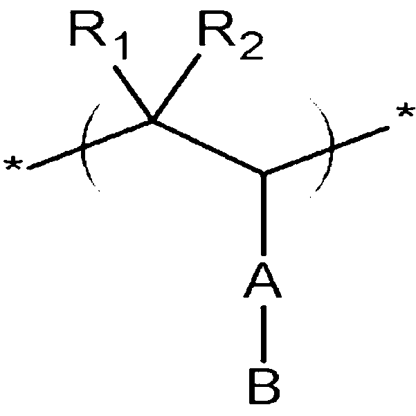
[Chemical Formula 1]
[Chemical Formula 2]
[Chemical Formula 3]
In the above Chemical Formulae 1 to 3,
R1, R2, R3, R4, R5, and R6 are independently selected from the group consisting of hydrogen; a substituted or unsubstituted alkyl; a substituted or unsubstituted heteroalkyl; a substituted or unsubstituted alkoxy; a substituted or unsubstituted heteroalkoxy; a substituted or unsubstituted aryl; a substituted or unsubstituted arylalkyl; a substituted or unsubstituted aryloxy; a substituted or unsubstituted heteroaryl; a substituted or unsubstituted heteroarylalkyl; a substituted or unsubstituted heteroaryloxy; a substituted or unsubstituted cycloalkyl; a substituted or unsubstituted heterocycloalkyl; a substituted or unsubstituted alkylester; a substituted or unsubstituted heteroalkylester; a substituted or unsubstituted arylester; a substituted or unsubstituted heteroarylester; and a halogen (F, Br, Cl, or I),
A is selected from the group consisting of a single bond; a substituted or unsubstituted alkylene; a substituted or unsubstituted heteroalkylene; a substituted or unsubstituted alkoxylene; a substituted or unsubstituted heteroalkoxylene; a substituted or unsubstituted arylene; a substituted or unsubstituted arylalkylene; a substituted or unsubstituted aryloxylene; a substituted or unsubstituted heteroarylene; a substituted or unsubstituted heteroarylalkylene; a substituted or unsubstituted heteroaryloxylene; a substituted or unsubstituted cycloalkylene; a substituted or unsubstituted heterocycloalkylene; a substituted or unsubstituted alkylene ester; a substituted or unsubstituted heteroalkylene ester; a substituted or unsubstituted arylene ester; and a substituted or unsubstituted heteroarylene ester,
B is an ion-pair of a cation and an anion, where the cation is selected from the group consisting of H+, a metal ion selected from the group consisting of Na+, K+, Li+, Mg2+, Zn2+, and Al3+, NR3
+ where R is H or a substituted or unsubstituted alkyl, and an organic ion of CH3(-CH2-)pO+ where p ranges from 1 to 50, and the anion is selected from the group consisting of PO3
2-, SO3
-, COO-, I-, and CH3COO-,
C is selected from the group consisting of a single bond; -O-; -S-; -NH-; a substituted or unsubstituted alkylene; a substituted or unsubstituted heteroalkylene; a substituted or unsubstituted arylene; a substituted or unsubstituted oxyalkylene; a substituted or unsubstituted hetero-oxyalkylene; a substituted or unsubstituted arylalkylene; a substituted or unsubstituted aryloxylene; a substituted or unsubstituted aryleneamine; a substituted or unsubstituted pyrrolene; a substituted or unsubstituted thiophenylene; a substituted or unsubstituted heteroarylene; a substituted or unsubstituted heteroarylalkylene; a substituted or unsubstituted heteroaryloxylene; a substituted or unsubstituted cycloalkylene; a substituted or unsubstituted heterocycloalkylene; a substituted or unsubstituted alkylene ester; a substituted or unsubstituted heteroalkylene ester; a substituted or unsubstituted arylene ester; and a substituted or unsubstituted heteroarylene ester,
D is selected from the group consisting of a substituted or unsubstituted polyphenylene, a substituted or unsubstituted polyphenylenevinylene, a polyaniline or a derivative thereof represented by the following Chemical Formula 4, a polypyrrole or a derivative thereof represented by the following Chemical Formula 5, a substituted or unsubstituted polythiophene or a derivative thereof, and a polymer of a cyclic monomer represented by the following Chemical Formula 6, and
E is a halogen-substituted carbon compound group that is substituted or unsubstituted with a heteroatom of nitrogen, phosphorus, sulfur, silicon, oxygen, and the like.
[Chemical Formula 4]
In the above Chemical Formula 4,
Ra, Rb, Rc, and Rd are independently selected from the group consisting of hydrogen; a substituted or unsubstituted C1-C30 alkyl; a substituted or unsubstituted C1-C30 heteroalkyl; a substituted or unsubstituted C1-C30 alkoxy; a substituted or unsubstituted C1-C30 heteroalkoxy; a substituted or unsubstituted C6-C30 aryl; a substituted or unsubstituted C6-C30 arylalkyl; a substituted or unsubstituted C6-C30 aryloxy; a substituted or unsubstituted C6-C30 arylamine; a substituted or unsubstituted C6-C30 pyrrole; a substituted or unsubstituted C6-C30 thiophene; a substituted or unsubstituted C2-C30 heteroaryl; a substituted or unsubstituted C2-C30 heteroarylalkyl; a substituted or unsubstituted C2-C30 heteroaryloxy; a substituted or unsubstituted C5-C20 cycloalkyl; a substituted or unsubstituted C2-C30 heterocycloalkyl; a substituted or unsubstituted C2-C30 alkylester; a substituted or unsubstituted C1-C30 heteroalkylester; a substituted or unsubstituted C6-C30 arylester; and a substituted or unsubstituted C2-C30 heteroarylester.
[Chemical Formula 5]
In the above Chemical Formula 5,
X is selected from the group consisting of -NH- or -NR-; -PH or -PR-; -O-; and -S- where R is a C1-C20 alkyl or a C6-C20 aryl, and
Re and Rf are independently selected from the group consisting of -NH2 or -NRR'; -PH2 or -PRR'; -OH or -OR; and -SH or -SR where R and R' are independently hydrogen, a C1-C20 alkyl, or a C6-C20 aryl; a C1-C30 alkyl; a C6-C30 aryl; a C1-C30 alkoxy; a C1-C30 heteroalkyl; a C1-C30 heteroalkoxy; a C6-C30 arylalkyl; a C6-C30 aryloxy; a C6-C30 arylamine; a C6-C30 pyrrole; a C6-C30 thiophene; a C2-C30 heteroaryl; a C2-C30 heteroarylalkyl; a C2-C30 heteroaryloxy; a C5-C20 cycloalkyl; a C2-C30 heterocycloalkyl; a C2-C30 alkylester; a C1-C30 heteroalkylester; a C6-C30 arylester; a C2-C30 heteroarylester; and a combination thereof.
[Chemical Formula 6]
In the above Chemical Formula 6,
X and Y are independently selected from the group consisting of -NH- or -NR-; -PH- or -PR-; -O-; and -S- where R is a C1-C20 alkyl or a C6-C20 aryl,
Z is -(CR1R2)x-CR3R4-(CR5R6)y where R1 to R6 are independently selected from the group consisting of -H, a C1-C20 alkyl radical, a C6-C14 aryl radical, or -CH2-ORi where Ri is -H, a C1-C6 alkyl acid group, a C2-C6 alkylester group, a C1-C6 heteroalkyl acid group, or a C1-C6 alkylsulfonic acid group, and
x and y are independently integers ranging from 0 to 5.
It is preferable that R1, R2, R3, R4, R5, and R6 are independently selected from the group consisting of a substituted or unsubstituted C1-C30 alkyl; a substituted or unsubstituted C1-C30 heteroalkyl; a substituted or unsubstituted C1-C30 alkoxy; a substituted or unsubstituted C1-C30 heteroalkoxy; a substituted or unsubstituted C6-C30 aryl; a substituted or unsubstituted C6-C30 arylalkyl; a substituted or unsubstituted C6-C30 aryloxy; a substituted or unsubstituted C2-C30 heteroaryl; a substituted or unsubstituted C2-C30 heteroarylalkyl; a substituted or unsubstituted C2-C30 heteroaryloxy; a substituted or unsubstituted C5-C20 cycloalkyl; a substituted or unsubstituted C2-C30 heterocycloalkyl; a substituted or unsubstituted C2-C30 alkylester; a substituted or unsubstituted C1-C30 heteroalkylester; a substituted or unsubstituted C6-C30 arylester; and a substituted or unsubstituted C2-C30 heteroarylester.
It is preferable that A is selected from the group consisting of a substituted or unsubstituted C1-C30 alkylene; a substituted or unsubstituted C1-C30 heteroalkylene; a substituted or unsubstituted C1-C30 alkoxylene; a substituted or unsubstituted C1-C30 heteroalkoxylene; a substituted or unsubstituted C6-C30 arylene; a substituted or unsubstituted C6-C30 arylalkylene; a substituted or unsubstituted C6-C30 aryloxylene; a substituted or unsubstituted C2-C30 heteroarylene; a substituted or unsubstituted C2-C30 heteroarylalkylene; a substituted or unsubstituted C2-C30 heteroaryloxylene; a substituted or unsubstituted C5-C20 cycloalkylene; a substituted or unsubstituted C2-C30 heterocycloalkylene; a substituted or unsubstituted C2-C30 alkylene ester; a substituted or unsubstituted C1-C30 heteroalkylene ester; a substituted or unsubstituted C6-C30 arylene ester; and a substituted or unsubstituted C2-C30 heteroarylene ester.
It is preferable that E is a halogen-substituted C2-C30 carbon compound group that is substituted or unsubstituted with a heteroatom of nitrogen, phosphorus, sulfur, silicon, oxygen, and the like.
It is preferable that D is added in a ratio of 1 to 50 wt% based on the total amount of conductive polymer, and it is more preferable that it ranges from 1 to 50 wt%, or it ranges from 1 to 20 wt%. When the D is added within the range of 1 to 50 wt%, it is possible to suppress the aggregation of a conductive polymer, so as to prevent precipitation in a solvent. In other words, when D is added at least 1 wt%, it may provide conductivity capable of applying to the organic photoelectric device. However, when it is added at less than 1 wt%, the hole injection characteristic is remarkably deteriorated since the conductivity is too low. Accordingly, when it is added within the range of 1 to 50 wt%, it may provide both suitable dispersion and suitable conductivity.
The conductive polymer having the composition increases the electrochemical stability since the conductive polymer is covalently bound with the doping polymer acid.
The conductive polymer has a lesser amount of a residual group decomposed by the reaction with electron, and decreases the intermolecular aggregation. Thereby, the organic photoelectric device including the conductive polymer may provide storage stability, high efficiency, and a long life-span.
The conductive polymer composition according to another embodiment includes a conductive polymer represented by the following Chemical Formula 12 and a solvent.
[Chemical Formula 12]
In the above Chemical Formula 12, R1, R2, R3, R4, R5, R6, A, B, C, D, and E are the same as in the above Chemical Formulae 1 to 3, and
5≤ℓ≤1,000,000, 0.0001≤m/ℓ≤0.2, 0.0001≤n/ℓ≤1, and 0.00000001≤m+n/ℓ≤1.1.
Preferably, ℓ, m, and n are in the ranges as follows: 5≤ℓ≤1,000, 0.01≤m/ℓ≤0.2, 0.01≤n/ℓ≤1, and 0.0001≤m+n/ℓ≤0.8.
The conductive polymer may further include at least one selected from the group consisting of repeating units represented by the following Chemical Formulae 7 to 11.
[Chemical Formula 7]
In the above Chemical Formula 7
M+ is selected from the group consisting of H+; an alkali metal cation; an alkaline-earth metal cation; and an ammonium ion (NH4
+, NH+
2R1R2, or NH+R1R2R3),
R1 to R3 are independently selected from the group consisting of hydrogen; a substituted or unsubstituted alkyl; a substituted or unsubstituted heteroalkyl; a substituted or unsubstituted alkoxy; a substituted or unsubstituted heteroalkoxy; a substituted or unsubstituted aryl; a substituted or unsubstituted arylalkyl; a substituted or unsubstituted aryloxy; a substituted or unsubstituted heteroaryl; a substituted or unsubstituted heteroarylalkyl; a substituted or unsubstituted heteroaryloxy; a substituted or unsubstituted cycloalkyl; a substituted or unsubstituted heterocycloalkyl; a substituted or unsubstituted alkylester; a substituted or unsubstituted heteroalkylester; a substituted or unsubstituted arylester; a substituted or unsubstituted heteroarylester; and a halogen, and a fluorine (F)-substituted one is preferable,
0<m<1,000,000, and
x and y are independently integers ranging from 0 to 20.
[Chemical Formula 8]
[Chemical Formula 9]
In the above Chemical Formulae 8 and 9,
M, m, x, and y are the same as in the above Chemical Formula 7, and
0<n<1,000,000.
[Chemical Formula 10]
In the above Chemical Formula 10,
M, m and n are the same as in the above Chemical Formula 8, and
z is an integer ranging from 0 to 20.
[Chemical Formula 11]
In the above Chemical Formula 11,
M, m, and n are the same as in the above Chemical Formula 8,
Rg includes 1% or more of a fluorine substituent based on total hydrogen and is selected from the group consisting of a substituted or unsubstituted C1-C30 alkyl; a substituted or unsubstituted C1-C30 heteroalkyl; a substituted or unsubstituted C1-C30 alkoxy; a substituted or unsubstituted C1-C30 heteroalkoxy; a substituted or unsubstituted C6-C30 aryl; a substituted or unsubstituted C6-C30 arylalkyl; a substituted or unsubstituted C6-C30 aryloxy; a substituted or unsubstituted C2-C30 heteroaryl; a substituted or unsubstituted C2-C30 heteroarylalkyl; a substituted or unsubstituted C2-C30 heteroaryloxy; a substituted or unsubstituted C5-C20 cycloalkyl; a substituted or unsubstituted C2-C30 heterocycloalkyl; a substituted or unsubstituted C2-C30 alkylester; a substituted or unsubstituted C1-C30 heteroalkylester; a substituted or unsubstituted C6-C30 arylester; a substituted or unsubstituted C2-C30 heteroarylester; and a halogen.
As mentioned above, the compound represented by Chemical Formula 12 is provided by polymerizing the repeating unit of Chemical Formula 1, Chemical Formula 2, and Chemical Formula 3. The C and D bond in Chemical Formula 4 has a more thermally stable structure than when the conductive polymer is simply doped.
In addition, a large amount of fluorine substituents prevents the aggregation of the ionomer as well as the intermolecular agglomeration, so it may decrease the surface roughness of the conductive polymer organic film.
It is preferable that D is added at 1 to 50 wt% based on the total amount of ionomer and conductive polymer, and it is more preferable that it is added at 1 to 20 wt%. When D is added within the range of 1 to 50 wt% based on the total amount of ionomer and conductive polymer, it is possible to prevent the aggregation of the conductive polymer composition, so as to prevent the precipitation in a solvent. In other words, when D is added at least 1 wt%, it may provide conductivity capable of applying to the organic photoelectric device. However, when it is added at less than 1 wt%, the hole injection characteristic is remarkably deteriorated since the conductivity is too low. Accordingly, when it is included within the range of 1 to 50 wt%, it is possible to suitably provide both dispersion and conductivity.
Any solvent that is capable of dissolving the conductive polymer can be used as a solvent for preparing the conductive polymer composition of the present invention. The solvent may be at least one selected from the group consisting of water, alcohol, dimethyl formamide (DMF), dimethylsulfoxide, toluene, xylene, and chlorobenzene.
In the conductive polymer composition of the present invention, the content of solid components, including a conductive polymer compound and/or a cross-linking agent, may range from 0.5 to 30 wt%, and more preferably from 0.5 to 10 wt%. When the content of the solid components falls in the range, the content of the solid component becomes appropriate and thus the concentration of the composition becomes appropriate as well. Since the concentration is appropriate, a thin film can be formed with a good shape, and this makes the process excellent.
The conductive polymer composition may further include a cross-linking agent to improve the cross-linking performance of the conductive polymer.
The cross-linking agent may be a hydroxyl-containing physical cross-linking agent, a hydroxyl-containing chemical cross-linking agent, or a combination thereof.
The physical cross-linking agent used in the present invention is a material for physically cross-linking polymer chains without chemical coupling. The physical cross-linking agent refers to a low-molecular or polymer compound containing a hydroxyl group (-OH). Examples of the physical cross-linking agent include low molecular compounds such as glycerol and butanol, and polymer compounds such as polyvinyl alcohol and polyethyleneglycol. Further, polyethyleneimine and polyvinylpyrrolidone can be used as the physical cross-linking agent.
The content of the physical cross-linking agent may range from 0.001 to 5 parts by weight with respect to 100 parts by weight of the conductive polymer, and more specifically from 0.1 to 3 parts by weight. When the content of the physical cross-linking agent falls in the range, the cross-linking agent performs efficiently, and the thin film morphology of the conductive polymer layer can be effectively maintained.
A chemical cross-linking agent is a material for chemically cross-linking polymer chains, and is a chemical material that is available for in-situ polymerization and is capable of forming an interpenetrating polymer network (IPN). As for the chemical cross-linking agent, silane materials are often used, and for example, tetraethyloxysilane (TEOS) is used as a chemical cross-linking agent. Further, polyaziridine, melamine materials, and epoxy materials can be used as the chemical cross-linking agent.
The content of the chemical cross-linking agent may range from 0.001 to 50 parts by weight with respect to 100 parts by weight of a conductive polymer, and more specifically from 1 to 10 parts by weight. When the content of the chemical cross-linking agent falls in the range, the cross-linking agent performs effectively and does not affect the conductive polymer to thereby maintain sufficient conductivity.
When a mixture of the physical cross-linking agent and the chemical cross-linking agent is used, the mixture can be prepared properly within their content ranges described above.
The conductive polymer composition of the present invention may further include an organic salt.
The organic salt transfers electrons of the conductive polymer in a device to thereby improve current stability, life-span, and electrochemical stability. Examples of the organic salt include imidazolium salt, thiazolium salt, pyridinium salt, pyrrolidinium salt, and piperidinium salt.
The content of the organic salt may range from 0.001 to 10 parts by weight with respect to 100 parts by weight of a conductive polymer compound, and more specifically from 0.01 to 3 parts by weight. When the content of the organic salt falls in the range of 0.001 to 10 parts by weight with respect to 100 parts by weight of a conductive polymer compound, there is an advantage in that the physical properties of the conductive polymer composition are not changed.
When the conductive polymer composition according to one embodiment of the present invention is used for fabrication of an organic photoelectric device, it is coated on a substrate. Herein, most of its solvent is removed and the conductive polymer composition remains as a conductive polymer organic film.
According to another embodiment, an organic photoelectric device including a conductive polymer organic film formed by using a conductive polymer composition is provided. The photoelectric device may be exemplified by organic light emitting diodes, organic solar cells, organic transistors, organic memory devices, and the like.
In an organic photoelectric device, the conductive polymer composition is used in a charge injection layer, that is, a hole or electron injection layer (EIL). The light emitting intensity and the efficiency of the organic photoelectric device are increased by uniformly and efficiently injecting holes and electrons.
Also, in the case of an organic solar cell, the conductive polymer layer composition of the present invention is used as an electrode or an electrode buffer layer to thereby increase quantum efficiency. In the case of an organic transistor, it can be used as an electrode material in a gate or source-drain electrode.
Hereinafter, the conductive polymer composition applied to an organic photoelectric device will be described.
The fabrication of an organic photoelectric device suggested in the present invention does not require a specific apparatus or method, and the organic photoelectric device of the present invention may be fabricated through an organic photoelectric device fabrication method using a typical conductive polymer composition.
FIGS. 1A to 1D show structures of organic photoelectric devices according to preferable embodiments.
The organic photoelectric device of FIG. 1A includes a light emission layer 12 formed above a first electrode 10, a hole injection layer (HIL) 11 including the conductive polymer composition of the present invention disposed between the first electrode 10 and the light emission layer, a hole blocking layer (HBL) 13 on top of the light emission layer 12, and a second electrode 14 on top of the hole blocking layer (HBL) 13. The hole injection layer (HIL) 11 may be referred to as a buffer layer.
The organic photoelectric device of FIG. 1B has the same stacking structure as that of FIG. 1A, except that an electron transport layer (ETL) 15 is formed instead of the hole blocking layer (HBL) 13 on top of the light emission layer 12.
The organic photoelectric device of FIG. 1C has the same stacking structure as that of FIG. 1A, except that a dual layer of the hole blocking layer (HBL) 13 and the electron transport layer (ETL) 15 sequentially stacked therein is formed on top of the light emission layer 12.
The organic photoelectric device of FIG. 1D has the same structure as that of FIG. 1C, except that a hole transport layer (HTL) 16 is formed between the hole injection layer (HIL) 11 and the light emission layer 12. Herein, the hole transport layer (HTL) 16 suppresses permeation of impurities from the hole injection layer (HIL) 11 to the emission layer 12.
The organic photoelectric device having the stacking structure of FIGS. 1A to 1D can be fabricated through a general fabrication method.
First, a patterned first electrode 10 is formed on a substrate. The substrate is a generally-used substrate for an organic photoelectric device, and may be a glass substrate or a transparent plastic substrate having excellent general transparence, surface smoothness, handling ease, and water repellency. The substrate has a thickness of 0.3 to 1.1 mm.
Materials for forming the first electrode 10 are not specifically limited. When the first electrode is a cathode, the cathode is formed using conductive metals or oxides thereof that easily performs hole injection. Examples of the materials include indium tin oxide (ITO), indium zinc oxide (IZO), nickel (Ni), platinum (Pt), gold (Au), iridium (Ir), and so on.
The substrate including the first electrode 10 is cleaned and is subjected to UV ozone treatment. An organic solvent such as isopropanol (IPA), acetone, and the like may be used for the cleaning process.
The hole injection layer (HIL) 11 is formed on the first electrode 10 of the cleaned substrate, and includes the conductive polymer composition of the present invention. The formation of the hole injection layer (HIL) 11 reduces contact resistance between the first electrode 10 and the light emission layer 12, and at the same time improves hole transfer capability of the first electrode 10 toward the light emission layer 12. Thus, the driving voltage and life-span characteristics of the device can be generally improved.
The hole injection layer HIL 11 is formed by dissolving the conductive polymer of the present invention, and optionally a cross-linking agent, in a solvent to thereby prepare a composition for forming a hole injection layer (HIL), coating the upper part of the first electrode 10 with the prepared composition for forming a hole injection layer (HIL) through a spin-coating process, and drying the composition.
Herein, the thickness of the hole injection layer (HIL) 11 may range from 5 to 200nm, and more specifically from 20 to 100nm. When the thickness of the hole injection layer (HIL) 11 falls in the range, the hole injection can be sufficiently performed, and the light transmission can be maintained at a good level.
A light emission layer 12 is disposed on the hole injection layer (HIL) 11. The light emission layer material is not specifically limited. Specific examples of the material include an oxadiazole dimer dye (Bis-DAPOXP)), spiro compounds (Spiro-DPVBi, Spiro-6P), triarylamine compounds, bis(styryl)amine (DPVBi, DSA), Flrpic, CzTT, anthracene, TPB, PPCP, DST, TPA, OXD-4, BBOT, and AZM-Zn (blue-emitting); coumarin 6, C545T, quinacridone, and Ir(ppy)3 (green-emitting); DCM1, DCM2, Eu(thenoyltrifluoroacetone)3 (Eu(TTA)3 and 1,1,7,7-tetramethyljulolidyl-9-enyl)-4H-pyran: DCJTB) (red-emitting), and the like. In addition, polymer light emitting materials may be used. The polymer light emitting materials include polymers such as phenylene-based, phenylene vinylene-based, thiophene-based, fluorine-based, and spiro-fluorene-based polymers or nitrogen-included aromatic compounds, but are not limited thereto.
The thickness of the emission layer 12 may range from 10 to 500nm, and more specifically from 50 to 120nm. When the thickness of the emission layer 12 falls in the range, leakage current amount and driving voltage increase can be appropriately maintained, and this effectively increases the life-span.
A dopant may be added to the composition for forming the light emission layer. The content of the dopant varies according to the material used for forming the light emission layer, but generally the content of the dopant may range from 30 to 80 parts by weight with respect to 100 parts by weight of the material for forming a light emission layer (total weight of host and dopant). When the content of the dopant falls in the range, the light emitting characteristics of the EL device can be effectively maintained. Examples of the dopant include an arylamine, peryl-based compounds, pyrrole-based compounds, hydrazone-based compounds, carbazole-based compounds, stilbene-based compounds, starburst-based compounds, and oxadiazole-based compounds.
A hole transport layer (HTL) 16 may be selectively formed between the hole injection layer (HIL) 11 and the emission layer 12.
A material for forming the hole transport layer (HTL) is not specifically limited. However, it may include at least one selected from the group consisting of compounds including a carbazole and/or an arylamine, which transport holes, phthalocyanine-based compounds, and triphenylene derivatives. The hole transport layer (HTL) material includes at least one material selected from the group consisting of 1,3,5-tricarbazolylbenzene, 4,4'-biscarbazolylbiphenyl, polyvinylcarbazole, m-biscarbazolylphenyl, 4,4'-biscarbazolyl-2,2'-dimethylbiphenyl, 4,4',4"-tri(N-carbazolyl)triphenylamine, 1,3,5-tri(2-carbazolylphenyl)benzene, 1,3,5-tris(2-carbazolyl-5-methoxyphenyl)benzene, bis(4-carbazolylphenyl)silane, N,N'-bis(3-methylphenyl)-N,N'-diphenyl-[1,1-biphenyl]-4,4'diamine (TPD), N,N'-di(naphthalen-1-yl)-N,N'-diphenyl benzidine (α-NPD), N,N'-diphenyl-N,N'-bis(1-naphthyl)-(1,1'-biphenyl)-4,4'-diamine (NPB), IDE320 (Idemitsu Kosan Co., Ltd.) poly(9,9-dioctylfluorene-co-N-(4-butylphenyl)diphenylamine) (TFB), and poly(9,9-dioctylfluorene-co-bis-N,N-phenyl-1,4-phenylenediamine) (PFB), but is not limited thereto.
The hole transport layer (HTL) 16 may have a thickness ranging from 1 to 100 nm, and more specifically from 5 to 50 nm. When the thickness of the hole transport layer (HTL) 16 falls in the range, the hole transport layer (HTL) 16 can maintain sufficient hole transport capability and an appropriate level of driving voltage.
A hole blocking layer 13 and/or an electron transport layer (ETL) 15 may be disposed on the light emission layer 12 through a deposition or spin coating method. The hole blocking layer 13 prevents excitons formed in a light emitting material from transferring to the electron transport layer (ETL) 15, or it prevents holes from transferring to the electron transport layer (ETL) 15.
Examples of a material for forming the hole blocking layer 13 include phenanthroline-based compounds (e.g., BCP of the UDC Company,), imidazole-based compounds, triazole-based compounds, oxadiazole-based compounds (e.g., a commercial product PBD), an aluminium complex (UDC Company), BAlq, and the like.
The electron transport layer ETL 15 includes a material selected from oxazole-based compounds, iso-oxazole-based compounds, triazole-based compounds, isothiazole-based compounds, oxadiazole-based compounds, thiadiazole-based compounds, perylene-based compounds, aluminium complexes (Alq3 (tris(8-quinolinolato)-aluminium)), BAlq, SAlq, Almq3, gallium complexes (Gaq'2OPiv), Gaq'2OAc, 2(Gaq'2), and the like.
The hole blocking layer has a thickness of 5nm to 100nm, and the electron transport layer (ETL) has a thickness of 5nm to 100nm. When the thickness of the hole blocking layer and electron transport layer (ETL) is out of the above range, electron transport or hole blocking performance is not sufficient.
The second electrode 14 is disposed on the stacking structure fabricated as above, and the resulting material is sealed to thereby complete the fabrication of an organic photoelectric device.
The materials for forming the second electrode 14 are not specifically restricted, but the materials may be metals with a small work function, such as Li, Cs, Ba, Ca, Ca/Al, LiF/Ca, LiF/Al, BaF2/Ca, Mg, Ag, Al, or alloys thereof, or multi-layers thereof. The thickness of the second electrode 14 may range from 50 to 3000 Å
Hereinafter, in the following examples, when a graft copolymer including a conductive polymer that is chemically bound with a polyacid is applied, it is not dedoped by heat generated in a device. In addition, the fluoric group may decrease the aggregation of the conductive polymer to increase the storage stability and suppress the moisture absorption. Accordingly, it is described that the efficiency characteristic and the life-span characteristic of the organic photoelectric device are improved with reference to particular exemplary embodiments. In the examples, the chemical formulas are not represented by precise chemical formulas, but they are illustrated as exemplary embodiments and have a random structure in a reaction for better understanding of this disclosure. Accordingly, the conductive polymer composition is illustrated as a random copolymer. A person having ordinary skills in this art can sufficiently understand parts of the present invention that are not specifically described.
<Synthesis Example 1>
Preparing Polymer A Precursor
12 g of sodium styrene sulfonate (SSNa) produced by the Sigma Aldrich Company (Chemical Formula 13-1), 3.4 g (corresponding to 30 mol% based on sodium styrene sulfonate (SSNa)) of pentafluorostyrene (Chemical Formula 15), and 0.83 g (corresponding to 5 mol% based on the total amount of two monomers) of 4-tert-butyloxycarbonylaminostyrene (Chemical Formula 14-1) were added to 100 ml of dimethylsulfoxide (DMSO) and heated to be completely dissolved.
0.3 g of azobisisobutyronitrile (AIBN) was dissolved in dimethylsulfoxide (DMSO) and added in a dropwise fashion to the obtained solution and then polymerized for more than 48 hours.
The obtained reactant was precipitated in acetone and allowed to stand at room temperature. The resultant precipitate was removed using a filter to provide a poly(sodium styrene sulfonate-tert-butyloxy carbonylaminostyrene-pentafluorostyrene) copolymer {P(SSNa-BOCAmS-PFS)}. The mole ratio of Chemical Formula 13-1:Chemical Formula 14-1:Chemical Formula 15 was 15:1:5.
[Chemical Formula 13-1]
[Chemical Formula 14-1]
[Chemical Formula 15]
Preparing Polymer A
The obtained polymer A precursor was dissolved in 250 ml of 3N HCl aqueous solution and agitated for one hour or longer. Then the produced NaCl salt was sufficiently removed using a cationic resin of Amberite IR-120 and a Prep/ScaleTFF membrane manufactured by Millipore to provide a poly(sodium styrene sulfonate-ammonium styrene-pentafluoro styrene) copolymer {P(SSNa-AmS-PFS)} aqueous solution having a random repeat unit of the following Chemical Formula 13-2, Chemical Formula 14-2, and Chemical Formula 15. The mole ratio of Chemical Formula 13-2:Chemical Formula 14-2:Chemical Formula 15 was 15:1:5.
[Chemical Formula 13-2]
[Chemical Formula 14-2]
<Synthesis Example 2>
Preparing Polymer A' Precursor
12 g of sodium styrene sulfonate (SSNa) produced by the Sigma Aldrich Company, 2.3 g (corresponding to 20 mol% based on sodium styrene sulfonate (SSNa)) of pentafluoro styrene, and 0.61 g (corresponding to 4 mol% based on two monomers) of 4-tertbutyloxycarbonylaminostyrene were added to 250 ml of dimethylsulfoxide (DMSO) and heated to be completely dissolved.
0.3 g of azobisisobutyronitrile (AIBN) was dissolved in dimethylsulfoxide (DMSO) and added in a dropwise fashion to the obtained solution and then polymerized for more than 48 hours.
The obtained reactant was precipitated in acetone and allowed to stand at room temperature. The precipitate was removed using a filter to provide a poly(sodium styrene sulfonate-tertbutyloxycarbonyl amino styrene-pentafluorostyrene) copolymer {P(SSNa-BOCAmS-PFS)}. The mole ratio of Chemical Formula 13-1:Chemical Formula 14-1:Chemical Formula 15 was 20:1:4.
Preparing Polymer A'
The obtained polymer was dissolved in 250 ml of 3N HCl aqueous solution and agitated for one hour or longer. Then the produced NaCl salts were sufficiently removed using a cationic resin of Amberite IR-120 and a Prep/ScaleTFF membrane manufactured by Millipore to provide a poly(styrene sulfonic acid-ammonium styrene-pentafluorostyrene) copolymer {P(SSA-AmS-PFS)} aqueous solution having a random repeat unit of Chemical Formula 13-2, Chemical Formula 14-2, and Chemical Formula 15. The mole ratio of Chemical Formula 13-2:Chemical Formula 14-2:Chemical Formula 15 was 20:1:4.
<Synthesis Example 3>
Preparing Polymer A" Precursor
12 g of sodium styrene sulfonate (SSNa) produced by the Sigma Aldrich Company, 1.6 g (corresponding to 10 mol% based on sodium styrene sulfonate (SSNa)) of pentafluoro styrene, and 0.61 g (4 mol% based on two monomers) of 4-tert-butyloxy carbonylamino styrene were added to 100 ml of dimethyl sulfoxide (DMSO) and heated to be completely dissolved.
0.3 g of azobisisobutyronitrile (AIBN) was dissolved in dimethylsulfoxide (DMSO) and added in a dropwise fashion and then polymerized for more than 48 hours.
The obtained reactant was precipitated in acetone and allowed to stand at room temperature. The precipitate was removed using a filter to provide a poly(sodium styrene sulfonate-tertbutyloxy carbonyl amino styrene-pentafluoro styrene) copolymer {P(SSNa-BOCAmS-PFS)} aqueous solution. The mole ratio of Chemical Formula 13-1:Chemical Formula 14-1:Chemical Formula 15 was 24:1:3.
Preparing Polymer A"
The obtained polymer was dissolved in 250 ml of 3N HCl aqueous solution and agitated for one hour or longer. Then the produced NaCl salts were sufficiently removed using a cationic resin of Amberite IR-120 and a Prep/ScaleTFF membrane manufactured by Millipore to provide a poly(styrenesulfonic acid-ammonium styrene-pentafluoro styrene) copolymer {P(SSA-AmS-PFS)} aqueous solution having a random repeat unit. The mole ratio of Chemical Formula 13-2:Chemical Formula 14-2:Chemical Formula 15 was 24:1:3.
<Synthesis Example 4>
Preparing Polymer B Precursor
12 g of sodium styrene sulfonate (SSNa) produced by the Sigma Aldrich Company and 0.61 g of 4-tert-butyloxycarbonylaminostyrene were added to 100 ml of dimethylsulfoxide (DMSO) and heated to be completely dissolved.
0.3 g of azobisisobutyronitrile (AIBN) was dissolved in dimethylsulfoxide (DMSO) and added in a dropwise fashion and then polymerized for more than 48 hours.
The obtained reactant was precipitated in acetone and allowed to stand at room temperature. The precipitate was removed using a filter to provide a poly(sodium styrene sulfonate-tertbutyloxycarbonyl aminostyrene) copolymer {P(SSNa-BOCAmS)} aqueous solution. The mole ratio of Chemical Formula 13-1:Chemical Formula 14-1 was 19:1.
Preparing Polymer B
The obtained polymer was dissolved in 250 ml of 3N HCl aqueous solution and agitated for one hour or longer. Then the produced NaCl salts were sufficiently removed using a cationic resin of Amberite IR-120 and a Prep/ScaleTFF membrane manufactured by Millipore to provide a poly(styrene sulfonic acid-ammonium styrene) copolymer {P(SSA-AmS)} aqueous solution having a random repeating unit. The mole ratio of Chemical Formula 13-2:Chemical Formula 14-2 was 19:1.
<Synthesis Example 5>
Preparing Polymer C Precursor
12 g of sodium styrene sulfonate (SSNa) produced by the Sigma Aldrich Company, 2.3 g (corresponding to 20 mol% based on sodium styrene sulfonate (SSNa)) of pentafluoro styrene, and 0.79 g (corresponding to 5 mol% based on two monomers) of 2-styrenyl(3,4-ethylenedioxy)pyrrole represented by the following Chemical Formula 16 were added into 250 ml of dimethyl sulfoxide (DMSO) and heated to be completely dissolved.
0.3 g of azobisisobutyronitrile (AIBN) was dissolved in dimethylsulfoxide (DMSO) and added in a dropwise fashion and then polymerized for more than 48 hours.
The obtained reactant was precipitated into acetone and allowed to stand at room temperature. The precipitate was removed using a filter to provide a poly(sodium styrene sulfonate-styrenyl (3,4-ethylenedioxy)pyrrole-pentafluoro styrene) copolymer {P(SSNa-StEDOP-PFS)}. The mole ratio of Chemical Formula 13-1:Chemical Formula 16:Chemical Formula 15 was 15:1:5.
[Chemical Formula 16]
Preparing Polymer C
The obtained polymer was dissolved in 250 ml of 3N HCl aqueous solution and agitated for one hour or longer. Then the produced NaCl slats was sufficiently removed using a cationic resin of Amberite IR-120 and a Prep/ScaleTFF membrane manufactured by Millipore to provide a poly(styrenesulfonic acid-styrenyl (3,4-ethylenedioxy)pyrrole-pentafluorostyrene) copolymer {P(SSA-StEDOP-PFS)} aqueous solution having a random repeating unit represented by Chemical Formula 13-2, Chemical Formula 16, and Chemical Formula 15. The mole ratio of Chemical Formula 13-2:Chemical Formula 16:Chemical Formula 15 was 15:1:5.
<Synthesis Example 6>
Preparing Polymer D Precursor
12 g of sodium styrene sulfonate (SSNa) produced by the Sigma Aldrich Company, 2.3 g (corresponding to 20 mol% based on sodium styrene sulfonate (SSNa)) of pentafluorostyrene, and 0.85 g (corresponding to 5 mol% based on two monomers) of 2-styrenyl (3,4-ethylenedioxy)thiophene represented by the following Chemical Formula 17 were added to 250 ml of dimethylsulfoxide (DMSO) and heated to be completely dissolved.
0.3 g of azobisisobutyronitrile (AIBN) was dissolved in dimethylsulfoxide (DMSO) and added in a dropwise fashion and then polymerized for more than 48 hours.
The obtained reactant was precipitated in acetone and allowed to stand at room temperature. The precipitate was removed using a filter to provide a poly(sodium styrene sulfonate-styrenyl (3,4-ethylenedioxy)thiophene-pentafluorostyrene) copolymer {P(SSNa-StEDOT-PFS)}. The mole ratio of Chemical Formula 13-1:Chemical Formula 17:Chemical Formula 15 was 16:1:3.
[Chemical Formula 17]
Preparing Polymer D
The obtained polymer was dissolved in 250 ml of 3N HCl aqueous solution and agitated for one hour or longer. Then the produced NaCl salts were sufficiently removed using a cationic resin of Amberite IR-120 and a Prep/ScaleTFF membrane manufactured by Millipore to provide a poly(styrenesulfonic acid-styrenyl (3,4-ethylenedioxy)thiophene-pentafluorostyrene) copolymer {P(SSA-StEDOT-PFS)} aqueous solution having a random repeating unit represented by Chemical Formula 13-2, Chemical Formula 17, and Chemical Formula 16. The mole ratio of Chemical Formula 13-2:Chemical Formula 17:Chemical Formula 16 was 15:1:3.
[Assessing Solubility of Polymer to Water]
The conductive polymer had a different solubility to water depending upon the ratio of the hydrophobic monomer represented by Chemical Formula 15, the monomer chemical binding with polyacid represented by Chemical Formula 14-1, the monomer represented by Chemical Formula 13-1, and hydrophilic sodium styrenesulfonate. Accordingly, Synthesis Examples 1 to 6 having the amount ratio as shown in Table 1 were measured to determine the solubility. The synthesized conductive polymer was prepared to provide a 2 wt% aqueous solution, and the filtering level was analyzed using a 0.45 ㎛ PVDF syringe filter having a diameter of 13mm. For indicating the solubility, O is assigned to the case of filtering at 3 ml or more; X is assigned to the case of not filtering at 0.5 ml or more; and △ is assigned to the case of filtering 0.5 ml or more and less than 3 ml. As shown in the following Table 1, all of Synthesis Examples 1 to 6 had excellent solubility.
Table 1
| Sample | Chemical Formula 13-1[mol%] | Chemical Formula 13-2[mol%] | Chemical Formula 14-1[mol%] | Chemical Formula 14-2[mol%] | Chemical Formula 15[mol%] | Chemical Formula 16[mol%] | Chemical Formula17[mol%] | Solubility |
| Synthesis Example 1-precursor | 15 | - | 1 | - | 5 | - | - | O |
| Synthesis Example 1 | - | 15 | - | 1 | 5 | - | - | O |
| Synthesis Example 2-precursor | 20 | - | 1 | - | 4 | - | - | O |
| Synthesis Example 2 | - | 20 | - | 1 | 4 | - | - | O |
| Synthesis Example 3-precursor | 24 | - | 1 | - | 3 | - | - | O |
| Synthesis Example 3 | - | 24 | - | 1 | 3 | - | - | O |
| Synthesis Example4-precursor | 19 | - | 1 | - | - | - | - | O |
| Synthesis Example 4 | - | 19 | - | 1 | - | - | - | O |
| Synthesis Example 5-precursor | 15 | - | - | - | 5 | 1 | - | O |
| Synthesis Example 5 | - | 15 | - | - | 5 | 1 | - | O |
| Synthesis Example 6-precursor | 16 | - | - | - | 3 | - | 1 | O |
| Synthesis Example 6 | - | 16 | - | - | 3 | - | 1 | O |
Preparing Self-doped Conductive Polymer Compound Solution
<Example 1>
A copolymer aqueous solution (copolymer amount: 2 g) represented by Synthesis Example 1 and 10 wt% of ionomer aqueous solution of NAFION represented by the following Chemical Formula 13 were mixed at a ratio of 1:1 to provide a solution. To the solution, aniline was added in water in an amount of 14 wt% based on 4 g of solid NAFION and the copolymer, and was polymerized using an ammonium persulfate oxidizing agent at 0 C for 12 hours to provide a self-doped conductive polymer. The resultant salts and side-product salts were purified in accordance with an ion exchange resin or dialysis.
[Chemical Formula 13]
A conductive polymer composition was prepared using the aqueous solution including the obtained self-doped conductive polymer compound. The conductive polymer was added at 1.2 to 1.5 wt% (solid amount ratio).
<Example 2>
A conductive polymer composition was prepared in accordance with the same procedure as in Example 1, except that the copolymer aqueous solution obtained from Synthesis Example 1 and NAFION were mixed in a ratio of 2:1 and polymerized instead of a ratio of 1:1.
<Example 3>
A conductive polymer composition was prepared in accordance with the same procedure as in Example 1, except that the copolymer aqueous solution obtained from Synthesis Example 1 and NAFION were mixed in a ratio of 5:1 and polymerized instead of a ratio of 1:1.
<Example 4>
A conductive polymer composition was prepared in accordance with the same procedure as in Example 1, except that the copolymer aqueous solution obtained from Synthesis Example 3 and NAFION were mixed in a ratio of 1:1 and polymerized instead of mixing the copolymer aqueous solution obtained from Synthesis Example 1 and NAFION in a ratio of 1:1 and polymerizing.
<Example 5>
A conductive polymer composition was prepared in accordance with the same procedure as in Example 4, except that the copolymer aqueous solution obtained from Synthesis Example 3 and NAFION were mixed in a ratio of 2:1 and polymerized instead of a ratio of 1:1.
<Example 6>
A conductive polymer composition was prepared in accordance with the same procedure as in Example 4, except that the copolymer aqueous solution obtained from Synthesis Example 3 and NAFION were mixed in a ratio of 5:1 and polymerized instead of a ratio of 1:1.
<Comparative Example 1>
A conductive polymer composition was prepared in accordance with the same procedure as in Example 1, except that the copolymer aqueous solution obtained from Synthesis Example 4 and NAFION were mixed in a ratio of 1:1 and polymerized instead of mixing the copolymer aqueous solution obtained from Synthesis Example 1 and NAFION in a ratio of 1:1 and polymerizing.
<Comparative Example 2>
A conductive polymer composition was prepared in accordance with the same procedure as in Comparative Example 1, except that the copolymer aqueous solution obtained from Synthesis Example 4 and NAFION were mixed in a ratio of 5:1 and polymerized instead of a ratio of 1:1.
<Comparative Example 3>
A conductive polymer composition was prepared in accordance with the same procedure as in Comparative Example 1, except that the copolymer aqueous solution obtained from Synthesis Example 4 and NAFION were blended in a ratio of 1:1 instead of mixing in a ratio of 1:1 and polymerizing.
<Comparative Example 4>
A conductive polymer composition was prepared in accordance with the same procedure as in Comparative Example 3, except that the copolymer aqueous solution obtained from Synthesis Example 4 and NAFION were blended in a ratio of 1:1 instead of blending in a ratio of 1:1.
<Comparative Example 5>
A conductive polymer composition was prepared in accordance with the same procedure as in Comparative Example 3, except that the copolymer aqueous solution obtained from Synthesis Example 4 and NAFION were blended in a ratio of 5:1 instead of blending in a ratio of 1:1.
[Assessing Solubility of Conductive Polymer Composition to Water]
In order to confirm the filtering property of the examples and comparative examples, 5 ml of each was filtered using a 0.45um PVDF syringe filter having a diameter of 13 mm to determine solubility. The results are shown in the following Table 2.For indicating the solubility, O is assigned to the case of filtering at 3 ml or more; X is assigned to the case of not filtering at 0.5 ml or more; and △ is assigned to the case of filtering at 0.5 ml or more and less than 3 ml.
[Assessing Roughness]
In order to assess the thin film characteristics of the examples and comparative examples, the surface roughness was measured using AFM equipment. The results are shown in the following Table 2.
Table 2
| Sample | Solubility | Roughness[nm] |
| Example 1 | O | 1.8 |
| Example 2 | O | 1.5 |
| Example 3 | O | 1.0 |
| Example 4 | O | 2.0 |
| Example 5 | O | 0.9 |
| Example 6 | O | 1.0 |
| Comparative Example 1 | X | >10 |
| Comparative Example 2 | X | 4.7 |
| Comparative Example 3 | △ | 3.1 |
| Comparative Example 4 | O | 2.7 |
| Comparative Example 5 | O | 2.2 |
Referring to Table 2, the conductive polymer compositions according to this disclosure had excellent solubility due to the hydrophobic group and decreased the aggregation of NAFION to compensate the surface roughness.
Fabrication of Organic Photoelectric Device
A 15Ψ/cm2 1200 ITO glass substrate from the Corning Company was cut in a size of width x length x thickness of 50mm x 50mm x 0.7mm, rinsed using ultrasonic waves in isopropyl alcohol and deionized water for 5 minutes, and cleaned with ultraviolet rays and ozone for 30 minutes.
The above-prepared substrate was spin-coated with the conductive polymer compositions of Examples 1, 2, 3, 6, and Comparative Example 5 to thereby form a 300 nm-thick hole injection layer (HIL).
A 700 nm-thick light emission layer was formed of a green light emitting polymer in the upper part of the hole injection unit, and a second electrode of LiF at 2 nm and Al at 100 nm was formed on the light emission layer to thereby fabricate an organic photoelectric device.
[Luminous Efficiency Characteristics]
Luminous efficiency of the organic photoelectric device according to Examples 1, 2, 3, and 6, and Comparative Example 5 was measured using a SpectraScan PR650 spectroradiometer. The results are shown in the following Table 3.
Table 3
| Sample | Efficiency (1000nit reference)(cd/A) | Max. efficiency(cd/A) | Driving voltage(@1000 nit)[Vd] |
| Example 1 | 7.5 | 11.6 | 5.2 |
| Example 2 | 8.7 | 10.7 | 5.0 |
| Example 3 | 7.0 | 9.5 | 5.1 |
| Example 6 | 6.4 | 7.0 | 5.0 |
| Comparative Example 5 | 3.1 | 2.1 | 5.5 |
Referring to Table 3, the organic photoelectric devices according to Examples 1 and 2 are good devices having excellent maximum luminous efficiency.
It is difficult to directly compare a device that is not yet optimized, but it is confirmed that the organic photoelectric device obtained from Examples 1 and 2 increased the maximum luminous efficiency by 200% or more compared to that of Comparative Example 5.
The present invention is not limited to the embodiments illustrated with the drawings and tables, but can be fabricated with various modifications and equivalent arrangements included within the spirit and scope of the appended claims by a person who is ordinarily skilled in this field. Therefore, the aforementioned embodiments should be understood to be exemplary but not limiting the present invention in any way.


 [Chemical Formula 2]
 [Chemical Formula 3]
 wherein in the above Chemical Formulae 1 to 3,R1, R2, R3, R4, R5, and R6 are independently selected from the group consisting of hydrogen; a substituted or unsubstituted alkyl; a substituted or unsubstituted heteroalkyl; a substituted or unsubstituted alkoxy; a substituted or unsubstituted heteroalkoxy; a substituted or unsubstituted aryl; a substituted or unsubstituted arylalkyl; a substituted or unsubstituted aryloxy; a substituted or unsubstituted heteroaryl; a substituted or unsubstituted heteroarylalkyl; a substituted or unsubstituted heteroaryloxy; a substituted or unsubstituted cycloalkyl; a substituted or unsubstituted heterocycloalkyl; a substituted or unsubstituted alkylester; a substituted or unsubstituted heteroalkylester; a substituted or unsubstituted arylester; a substituted or unsubstituted heteroarylester, and a halogen (F, Br, Cl, or I),A is selected from the group consisting of a single bond; a substituted or unsubstituted alkylene; a substituted or unsubstituted heteroalkylene; a substituted or unsubstituted alkoxylene; a substituted or unsubstituted heteroalkoxylene; a substituted or unsubstituted arylene; a substituted or unsubstituted arylalkylene; a substituted or unsubstituted aryloxylene; a substituted or unsubstituted heteroarylene; a substituted or unsubstituted heteroarylalkylene; a substituted or unsubstituted heteroaryloxylene; a substituted or unsubstituted cycloalkylene; a substituted or unsubstituted heterocycloalkylene; a substituted or unsubstituted alkylene ester; a substituted or unsubstituted heteroalkylene ester; a substituted or unsubstituted arylene ester; and a substituted or unsubstituted heteroarylene ester,B is an ion-pair of a cation and an anion, where the cation is selected from the group consisting of H+, a metal ion selected from the group consisting of Na+, K+, Li+, Mg2+, Zn2+, and Al3+, NR3 + where R is H or a substituted or unsubstituted alkyl, and an organic ion of CH3(-CH2-)pO+ where p ranges from 1 to 50, and the anion is selected from the group consisting of PO3 2-, SO3 -, COO-, I-, and CH3COO-,C is selected from the group consisting of a single bond; -O-; -S-; -NH-; a substituted or unsubstituted alkylene; a substituted or unsubstituted heteroalkylene; a substituted or unsubstituted arylene; a substituted or unsubstituted oxyalkylene; a substituted or unsubstituted hetero-oxyalkylene; a substituted or unsubstituted arylalkylene; a substituted or unsubstituted aryloxylene; a substituted or unsubstituted aryleneamine; a substituted or unsubstituted pyrrolene; a substituted or unsubstituted thiophenylene; a substituted or unsubstituted heteroarylene; a substituted or unsubstituted heteroarylalkylene; a substituted or unsubstituted heteroaryloxylene; a substituted or unsubstituted cycloalkylene; a substituted or unsubstituted heterocycloalkylene; a substituted or unsubstituted alkylene ester; a substituted or unsubstituted heteroalkylene ester; a substituted or unsubstituted arylene ester; and a substituted or unsubstituted heteroarylene ester,D is selected from the group consisting of a substituted or unsubstituted polyphenylene, a substituted or unsubstituted polyphenylenevinylene, polyaniline or a derivative thereof represented by the following Chemical Formula 4, a polypyrrole or a derivative thereof represented by the following Chemical Formula 5, a substituted or unsubstituted polythiophene or a derivative thereof, and a polymer of a cyclic monomer represented by the following Chemical Formula 6, andE is a halogen-substituted carbon compound group that is substituted or unsubstituted with a heteroatom of nitrogen, phosphorus, sulfur, silicon, or oxygen,[Chemical Formula 4]
 wherein in the above Chemical Formula 4,Ra, Rb, Rc, and Rd are independently selected from the group consisting of hydrogen; a substituted or unsubstituted C1-C30 alkyl; a substituted or unsubstituted C1-C30 heteroalkyl; a substituted or unsubstituted C1-C30 alkoxy; a substituted or unsubstituted C1-C30 heteroalkoxy; a substituted or unsubstituted C6-C30 aryl; a substituted or unsubstituted C6-C30 arylalkyl; a substituted or unsubstituted C6-C30 aryloxy; a substituted or unsubstituted C6-C30 arylamine; a substituted or unsubstituted C6-C30 pyrrole; a substituted or unsubstituted C6-C30 thiophene; a substituted or unsubstituted C2-C30 heteroaryl; a substituted or unsubstituted C2-C30 heteroarylalkyl; a substituted or unsubstituted C2-C30 heteroaryloxy; a substituted or unsubstituted C5-C20 cycloalkyl; a substituted or unsubstituted C2-C30 heterocycloalkyl; a substituted or unsubstituted C2-C30 alkylester; a substituted or unsubstituted C1-C30 heteroalkylester; a substituted or unsubstituted C6-C30 arylester; and a substituted or unsubstituted C2-C30 heteroarylester,[Chemical Formula 5]
 wherein in the above Chemical Formula 5,X is selected from the group consisting of -NH- or -NR-; -PH or -PR-; -O-; and -S- where R is a C1-C20 alkyl or a C6-C20 aryl, andRe and Rf are independently selected from the group consisting of -NH2 or -NRR'; -PH2 or -PRR'; -OH or -OR; and -SH or -SR where R and R' are independently hydrogen, a C1-C20 alkyl, or a C6-C20 aryl; a C1-C30 alkyl; a C6-C30 aryl; a C1-C30 alkoxy; a C1-C30 heteroalkyl; a C1-C30 heteroalkoxy; a C6-C30 arylalkyl; a C6-C30 aryloxy; a C6-C30 arylamine; a C6-C30 pyrrole; a C6-C30 thiophene; a C2-C30 heteroaryl; a C2-C30 heteroarylalkyl; a C2-C30 heteroaryloxy; a C5-C20 cycloalkyl; a C2-C30 heterocycloalkyl; a C2-C30 alkylester; a C1-C30 heteroalkylester; a C6-C30 arylester; a C2-C30 heteroarylester, and a combination thereof,[Chemical Formula 6]
 wherein in the above Chemical Formula 6,X and Y are independently selected from the group consisting of -NH- or -NR-; -PH- or -PR-; -O-; and -S- where R is a C1-C20 alkyl or a C6-C20 aryl,Z is -(CR1R2)x-CR3R4-(CR5R6)y where R1 to R6 are independently selected from the group consisting of -H, a C1-C20 alkyl radical, a C6-C14 aryl radical, or -CH2-ORi where Ri is -H, a C1-C6 alkyl acid group, a C2-C6 alkylester group, a C1-C6 heteroalkyl acid group, or a C1-C6 alkylsulfonic acid group, andx and y are independently integers ranging from 0 to 5.
 wherein in the above Chemical Formula 12,R1, R2, R3, R4, R5, and R6 are independently selected from the group consisting of hydrogen; a substituted or unsubstituted alkyl; a substituted or unsubstituted heteroalkyl; a substituted or unsubstituted alkoxy; a substituted or unsubstituted heteroalkoxy; a substituted or unsubstituted aryl; a substituted or unsubstituted arylalkyl; a substituted or unsubstituted aryloxy; a substituted or unsubstituted heteroaryl; a substituted or unsubstituted heteroarylalkyl; a substituted or unsubstituted heteroaryloxy; a substituted or unsubstituted cycloalkyl; a substituted or unsubstituted heterocycloalkyl; a substituted or unsubstituted alkylester; a substituted or unsubstituted heteroalkylester; a substituted or unsubstituted arylester; a substituted or unsubstituted heteroarylester; and a halogen (F, Br, Cl, or I),A is selected from the group consisting of a single bond; a substituted or unsubstituted alkylene; a substituted or unsubstituted heteroalkylene; a substituted or unsubstituted alkoxylene; a substituted or unsubstituted heteroalkoxylene; a substituted or unsubstituted arylene; a substituted or unsubstituted arylalkylene; a substituted or unsubstituted aryloxylene; a substituted or unsubstituted heteroarylene; a substituted or unsubstituted heteroarylalkylene; a substituted or unsubstituted heteroaryloxylene; a substituted or unsubstituted cycloalkylene; a substituted or unsubstituted heterocycloalkylene; a substituted or unsubstituted alkylene ester; a substituted or unsubstituted heteroalkylene ester; a substituted or unsubstituted arylene ester; and a substituted or unsubstituted heteroarylene ester,B is an ion-pair of a cation and an anion, where the cation is selected from the group consisting of H+, a metal ion selected from the group consisting of Na+, K+, Li+, Mg2+, Zn2+, and Al3+, NR3 + where R is H or a substituted or unsubstituted alkyl, and an organic ion of CH3(-CH2-)pO+ where p ranges from 1 to 50, and the anion is selected from the group consisting of PO3 2-, SO3 -, COO-, I-, and CH3COO-,C is selected from the group consisting of a single bond; -O-; -S-; -NH-; a substituted or unsubstituted alkylene; a substituted or unsubstituted heteroalkylene; a substituted or unsubstituted arylene; a substituted or unsubstituted oxyalkylene; a substituted or unsubstituted hetero-oxyalkylene; a substituted or unsubstituted arylalkylene; a substituted or unsubstituted aryloxylene; a substituted or unsubstituted aryleneamine; a substituted or unsubstituted pyrrolene; a substituted or unsubstituted thiophenylene; a substituted or unsubstituted heteroarylene; a substituted or unsubstituted heteroarylalkylene; a substituted or unsubstituted heteroaryloxylene; a substituted or unsubstituted cycloalkylene; a substituted or unsubstituted heterocycloalkylene; a substituted or unsubstituted alkylene ester; a substituted or unsubstituted heteroalkylene ester; a substituted or unsubstituted arylene ester; and a substituted or unsubstituted heteroarylene ester,D is selected from the group consisting of a substituted or unsubstituted polyphenylene, a substituted or unsubstituted polyphenylenevinylene, polyaniline or a derivative thereof represented by the following Chemical Formula 4, polypyrrole or a derivative thereof represented by the following Chemical Formula 5, a substituted or unsubstituted polythiophene or a derivative thereof, and a polymer of a cyclic monomer represented by the following Chemical Formula 6,E is a halogen-substituted carbon compound group that is substituted or unsubstituted with a heteroatom of nitrogen, phosphorus, sulfur, silicon, or oxygen, and5≤ℓ≤1,000,000, 0.0001≤m/ℓ≤0.2, 0.0001≤n/ℓ≤1, and 0.00000001≤m+n/ℓ≤1.1,[Chemical Formula 4]
 wherein in the above Chemical Formula 4,Ra, Rb, Rc, and Rd are independently selected from the group consisting of hydrogen; a substituted or unsubstituted C1-C30 alkyl; a substituted or unsubstituted C1-C30 heteroalkyl; a substituted or unsubstituted C1-C30 alkoxy; a substituted or unsubstituted C1-C30 heteroalkoxy; a substituted or unsubstituted C6-C30 aryl; a substituted or unsubstituted C6-C30 arylalkyl; a substituted or unsubstituted C6-C30 aryloxy; a substituted or unsubstituted C6-C30 arylamine; a substituted or unsubstituted C6-C30 pyrrole; a substituted or unsubstituted C6-C30 thiophene; a substituted or unsubstituted C2-C30 heteroaryl; a substituted or unsubstituted C2-C30 heteroarylalkyl; a substituted or unsubstituted C2-C30 heteroaryloxy; a substituted or unsubstituted C5-C20 cycloalkyl; a substituted or unsubstituted C2-C30 heterocycloalkyl; a substituted or unsubstituted C2-C30 alkylester; a substituted or unsubstituted C1-C30 heteroalkylester; a substituted or unsubstituted C6-C30 arylester; and a substituted or unsubstituted C2-C30 heteroarylester,[Chemical Formula 5]
 wherein in the above Chemical Formula 5,X is selected from the group consisting of -NH- or -NR-; -PH or -PR-; -O-; and -S- where R is a C1-C20 alkyl or a C6-C20 aryl, andRe and Rf are independently selected from the group consisting of -NH2 or -NRR'; -PH2 or -PRR'; -OH or -OR; and -SH or -SR where R and R' are independently hydrogen, a C1-C20 alkyl, or a C6-C20 aryl; a C1-C30 alkyl; a C6-C30 aryl; a C1-C30 alkoxy; a C1-C30 heteroalkyl; a C1-C30 heteroalkoxy; a C6-C30 arylalkyl; a C6-C30 aryloxy; a C6-C30 arylamine; a C6-C30 pyrrole; a C6-C30 thiophene; a C2-C30 heteroaryl; a C2-C30 heteroarylalkyl; a C2-C30 heteroaryloxy; a C5-C20 cycloalkyl; a C2-C30 heterocycloalkyl; a C2-C30 alkylester; a C1-C30 heteroalkylester; a C6-C30 arylester; a C2-C30 heteroarylester; and a combination thereof,[Chemical Formula 6]
 wherein in the above Chemical Formula 6,X and Y are independently selected from the group consisting of -NH- or -NR-; -PH- or -PR-; -O-; and -S- where R is a C1-C20 alkyl or a C6-C20 aryl,Z is -(CR1R2)x-CR3R4-(CR5R6)y where R1 to R6 are independently selected from the group consisting of -H, a C1-C20 alkyl radical, a C6-C14 aryl radical, or -CH2-ORi where Ri is -H, a C1-C6 alkyl acid group, a C2-C6 alkylester group, a C1-C6 heteroalkyl acid group, or a C1-C6 alkylsulfonic acid group, andx and y are independently integers ranging from 0 to 5.
 wherein in the above Chemical Formula 7M+ is selected from the group consisting of H+; an alkali metal cation; an alkaline-earth metal cation; and an ammonium ion (NH4 +, NH+ 2R1R2, or NH+R1R2R3),R1 to R3 are independently selected from the group consisting of hydrogen; a substituted or unsubstituted alkyl; a substituted or unsubstituted heteroalkyl; a substituted or unsubstituted alkoxy; a substituted or unsubstituted heteroalkoxy; a substituted or unsubstituted aryl; a substituted or unsubstituted arylalkyl; a substituted or unsubstituted aryloxy; a substituted or unsubstituted heteroaryl; a substituted or unsubstituted heteroarylalkyl; a substituted or unsubstituted heteroaryloxy; a substituted or unsubstituted cycloalkyl; a substituted or unsubstituted heterocycloalkyl; a substituted or unsubstituted alkylester; a substituted or unsubstituted heteroalkylester; a substituted or unsubstituted arylester; a substituted or unsubstituted heteroarylester; and a halogen, and a fluorine (F)-substituted one is preferable,0<m<1,000,000, andx and y are independently integers ranging from 0 to 20,[Chemical Formula 8]
 [Chemical Formula 9]
 wherein in the above Chemical Formulae 8 and 9,M, m, x and y are the same as in the above Chemical Formula 7, and0<n<1,000,000,[Chemical Formula 10]
 wherein in the above Chemical Formula 10,M, m, and n are the same as in the above Chemical Formula 8, andz is an integer ranging from 0 to 20,[Chemical Formula 11]
 wherein in the above Chemical Formula 11,M, m, n are the same as in the above Chemical Formula 8, andRg comprises 1% or more of a fluorine substituent based on total hydrogen and is selected from the group consisting of a substituted or unsubstituted C1-C30 alkyl; a substituted or unsubstituted C1-C30 heteroalkyl; a substituted or unsubstituted C1-C30 alkoxy; a substituted or unsubstituted C1-C30 heteroalkoxy; a substituted or unsubstituted C6-C30 aryl; a substituted or unsubstituted C6-C30 arylalkyl; a substituted or unsubstituted C6-C30 aryloxy; a substituted or unsubstituted C2-C30 heteroaryl; a substituted or unsubstituted C2-C30 heteroarylalkyl; a substituted or unsubstituted C2-C30 heteroaryloxy; a substituted or unsubstituted C5-C20 cycloalkyl; a substituted or unsubstituted C2-C30 heterocycloalkyl; a substituted or unsubstituted C2-C30 alkylester; a substituted or unsubstituted C1-C30 heteroalkylester; a substituted or unsubstituted C6-C30 arylester; a substituted or unsubstituted C2-C30 heteroarylester; and a halogen.