WO2010007646A1 - Intraocular lens and its manufacturing method - Google Patents
Intraocular lens and its manufacturing method Download PDFInfo
- Publication number
- WO2010007646A1 WO2010007646A1 PCT/JP2008/001901 JP2008001901W WO2010007646A1 WO 2010007646 A1 WO2010007646 A1 WO 2010007646A1 JP 2008001901 W JP2008001901 W JP 2008001901W WO 2010007646 A1 WO2010007646 A1 WO 2010007646A1
- Authority
- WO
- WIPO (PCT)
- Prior art keywords
- lens
- mold
- intraocular lens
- linear
- circumferential direction
- Prior art date
Links
Images


Classifications
-
- A—HUMAN NECESSITIES
- A61—MEDICAL OR VETERINARY SCIENCE; HYGIENE
- A61F—FILTERS IMPLANTABLE INTO BLOOD VESSELS; PROSTHESES; DEVICES PROVIDING PATENCY TO, OR PREVENTING COLLAPSING OF, TUBULAR STRUCTURES OF THE BODY, e.g. STENTS; ORTHOPAEDIC, NURSING OR CONTRACEPTIVE DEVICES; FOMENTATION; TREATMENT OR PROTECTION OF EYES OR EARS; BANDAGES, DRESSINGS OR ABSORBENT PADS; FIRST-AID KITS
- A61F2/00—Filters implantable into blood vessels; Prostheses, i.e. artificial substitutes or replacements for parts of the body; Appliances for connecting them with the body; Devices providing patency to, or preventing collapsing of, tubular structures of the body, e.g. stents
- A61F2/02—Prostheses implantable into the body
- A61F2/14—Eye parts, e.g. lenses, corneal implants; Implanting instruments specially adapted therefor; Artificial eyes
- A61F2/16—Intraocular lenses
- A61F2/1613—Intraocular lenses having special lens configurations, e.g. multipart lenses; having particular optical properties, e.g. pseudo-accommodative lenses, lenses having aberration corrections, diffractive lenses, lenses for variably absorbing electromagnetic radiation, lenses having variable focus
-
- B—PERFORMING OPERATIONS; TRANSPORTING
- B29—WORKING OF PLASTICS; WORKING OF SUBSTANCES IN A PLASTIC STATE IN GENERAL
- B29C—SHAPING OR JOINING OF PLASTICS; SHAPING OF MATERIAL IN A PLASTIC STATE, NOT OTHERWISE PROVIDED FOR; AFTER-TREATMENT OF THE SHAPED PRODUCTS, e.g. REPAIRING
- B29C33/00—Moulds or cores; Details thereof or accessories therefor
- B29C33/38—Moulds or cores; Details thereof or accessories therefor characterised by the material or the manufacturing process
- B29C33/40—Plastics, e.g. foam or rubber
-
- B—PERFORMING OPERATIONS; TRANSPORTING
- B29—WORKING OF PLASTICS; WORKING OF SUBSTANCES IN A PLASTIC STATE IN GENERAL
- B29C—SHAPING OR JOINING OF PLASTICS; SHAPING OF MATERIAL IN A PLASTIC STATE, NOT OTHERWISE PROVIDED FOR; AFTER-TREATMENT OF THE SHAPED PRODUCTS, e.g. REPAIRING
- B29C71/00—After-treatment of articles without altering their shape; Apparatus therefor
- B29C71/04—After-treatment of articles without altering their shape; Apparatus therefor by wave energy or particle radiation, e.g. for curing or vulcanising preformed articles
-
- B—PERFORMING OPERATIONS; TRANSPORTING
- B29—WORKING OF PLASTICS; WORKING OF SUBSTANCES IN A PLASTIC STATE IN GENERAL
- B29D—PRODUCING PARTICULAR ARTICLES FROM PLASTICS OR FROM SUBSTANCES IN A PLASTIC STATE
- B29D11/00—Producing optical elements, e.g. lenses or prisms
-
- B—PERFORMING OPERATIONS; TRANSPORTING
- B29—WORKING OF PLASTICS; WORKING OF SUBSTANCES IN A PLASTIC STATE IN GENERAL
- B29D—PRODUCING PARTICULAR ARTICLES FROM PLASTICS OR FROM SUBSTANCES IN A PLASTIC STATE
- B29D11/00—Producing optical elements, e.g. lenses or prisms
- B29D11/00009—Production of simple or compound lenses
- B29D11/00317—Production of lenses with markings or patterns
- B29D11/00326—Production of lenses with markings or patterns having particular surface properties, e.g. a micropattern
-
- B—PERFORMING OPERATIONS; TRANSPORTING
- B29—WORKING OF PLASTICS; WORKING OF SUBSTANCES IN A PLASTIC STATE IN GENERAL
- B29D—PRODUCING PARTICULAR ARTICLES FROM PLASTICS OR FROM SUBSTANCES IN A PLASTIC STATE
- B29D11/00—Producing optical elements, e.g. lenses or prisms
- B29D11/02—Artificial eyes from organic plastic material
- B29D11/023—Implants for natural eyes
-
- B—PERFORMING OPERATIONS; TRANSPORTING
- B29—WORKING OF PLASTICS; WORKING OF SUBSTANCES IN A PLASTIC STATE IN GENERAL
- B29D—PRODUCING PARTICULAR ARTICLES FROM PLASTICS OR FROM SUBSTANCES IN A PLASTIC STATE
- B29D16/00—Producing articles with corrugations
-
- A—HUMAN NECESSITIES
- A61—MEDICAL OR VETERINARY SCIENCE; HYGIENE
- A61F—FILTERS IMPLANTABLE INTO BLOOD VESSELS; PROSTHESES; DEVICES PROVIDING PATENCY TO, OR PREVENTING COLLAPSING OF, TUBULAR STRUCTURES OF THE BODY, e.g. STENTS; ORTHOPAEDIC, NURSING OR CONTRACEPTIVE DEVICES; FOMENTATION; TREATMENT OR PROTECTION OF EYES OR EARS; BANDAGES, DRESSINGS OR ABSORBENT PADS; FIRST-AID KITS
- A61F2/00—Filters implantable into blood vessels; Prostheses, i.e. artificial substitutes or replacements for parts of the body; Appliances for connecting them with the body; Devices providing patency to, or preventing collapsing of, tubular structures of the body, e.g. stents
- A61F2/0077—Special surfaces of prostheses, e.g. for improving ingrowth
- A61F2002/009—Special surfaces of prostheses, e.g. for improving ingrowth for hindering or preventing attachment of biological tissue
-
- A—HUMAN NECESSITIES
- A61—MEDICAL OR VETERINARY SCIENCE; HYGIENE
- A61F—FILTERS IMPLANTABLE INTO BLOOD VESSELS; PROSTHESES; DEVICES PROVIDING PATENCY TO, OR PREVENTING COLLAPSING OF, TUBULAR STRUCTURES OF THE BODY, e.g. STENTS; ORTHOPAEDIC, NURSING OR CONTRACEPTIVE DEVICES; FOMENTATION; TREATMENT OR PROTECTION OF EYES OR EARS; BANDAGES, DRESSINGS OR ABSORBENT PADS; FIRST-AID KITS
- A61F2/00—Filters implantable into blood vessels; Prostheses, i.e. artificial substitutes or replacements for parts of the body; Appliances for connecting them with the body; Devices providing patency to, or preventing collapsing of, tubular structures of the body, e.g. stents
- A61F2/02—Prostheses implantable into the body
- A61F2/14—Eye parts, e.g. lenses, corneal implants; Implanting instruments specially adapted therefor; Artificial eyes
- A61F2/16—Intraocular lenses
- A61F2002/1681—Intraocular lenses having supporting structure for lens, e.g. haptics
-
- B—PERFORMING OPERATIONS; TRANSPORTING
- B29—WORKING OF PLASTICS; WORKING OF SUBSTANCES IN A PLASTIC STATE IN GENERAL
- B29L—INDEXING SCHEME ASSOCIATED WITH SUBCLASS B29C, RELATING TO PARTICULAR ARTICLES
- B29L2011/00—Optical elements, e.g. lenses, prisms
- B29L2011/0016—Lenses
Definitions
- the present invention relates to an intraocular lens used in a state of being accommodated in a capsular bag, and more particularly to an intraocular lens that is effective in suppressing secondary cataract.
- an intraocular lens that replaces the crystalline lens has been used in the treatment of eye diseases such as cataracts.
- Such an intraocular lens is generally small by folding and removing the lens in the capsule through an incision formed in an eye tissue such as the cornea (capsular membrane) or the anterior lens capsule, and then using an insertion device. In this state, it is inserted into the sac through the incision.
- the intraocular lens inserted into the sac is deployed in the sac, and the optical unit that substitutes for the function of the crystalline lens is used in a stored state in which it is positioned and fixed in the sac by the support unit.
- the secondary cataract is a phenomenon in which the lens epithelial cells circulate around the back surface of the intraocular lens and proliferate after the operation, thereby causing the posterior capsule on the back side of the intraocular lens to become cloudy and causing a decrease in visual acuity.
- a sharp sharp edge shape is imparted to the outer peripheral edge portion of the rear surface of the optical part of the intraocular lens.
- a technique is known in which the sharp edge is pressed against the posterior capsule in the state of being accommodated in the sac, thereby suppressing the lens epithelial cells from entering the lens rear surface.
- the sharp edge shape leads to thickening of the optical part, and it is necessary to enlarge the incision for insertion into the sac, and it becomes difficult to fold at the time of insertion. Had.
- Patent Document 3 at least one annular groove continuously extending in the circumferential direction on the outer peripheral portion of the intraocular lens is formed with a cross section having a size sufficient to accommodate the lens epithelial cells.
- Intraocular lenses have been proposed in which the surface of the groove is an irregular surface with fine irregularities. According to such an intraocular lens, a lens epithelial cell is captured by the annular groove in the outer peripheral portion of the lens by a structure in which these large annular grooves and irregular irregular surfaces are combined. It is said that the growth to the part can be suppressed.
- the combined structure of the large annular groove and the irregular surface of the fine irregularities as described in Patent Document 3 has a structure in which the annular groove is formed on the retina in order to capture the lens epithelial cells and obtain an effective cell growth inhibitory effect. It must be formed in such a size that it becomes an opaque part that cannot be condensed. Therefore, the intraocular lens described in Patent Document 3 has an opaque portion that cannot be used as an effective optical portion in the outer peripheral portion where the annular groove is formed.
- the effective optical part of the intraocular lens is housed in the capsular sac to ensure a good amount of light, etc. under conditions where the outer diameter is limited, and to provide a good field of view so as to be surely overlapped with the entire pupil It is desirable to form as large as possible.
- the intraocular lens as described in Patent Document 3 has an outer peripheral portion that is an opaque portion, so that an effective optical portion cannot be sufficiently secured, and it is difficult to provide a good field of view. Had a problem.
- An object of the present invention is to provide an intraocular lens having a novel structure that can be exerted.
- Another object of the present invention is to provide a novel method for producing an intraocular lens that can advantageously produce such an intraocular lens.
- the first aspect of the present invention relating to an intraocular lens is an intraocular lens used in a state of being accommodated in a crystalline lens capsule, wherein at least a part of the lens surface is directly formed with a large number of minute irregularities.
- the minute irregularities are linear minute irregularities having a depth dimension of 0.01 to 1.0 ⁇ m and a width dimension of 0.1 to 2.0 ⁇ m and extending in a predetermined length in the circumferential direction of the lens surface,
- the linear micro unevenness in a chain structure that is continuous in the circumferential direction of the lens surface and a periodic structure that is periodically arranged in a direction perpendicular to the circumferential direction of the lens surface,
- the linear minute irregularities are formed without gaps, and the visible light transmittance in the cell induction region is 60% or more.
- the linear epithelium formed in the cell guiding region and extending in the circumferential direction of the lens indicates the direction in which lens epithelial cells that are thought to cause secondary cataract proliferate.
- the proliferation stops by contact inhibition (contact inhibition). Thereby, it can suppress that a cell proliferates toward a lens center part, and can exhibit the outstanding inhibitory effect with respect to a secondary cataract.
- the present invention does not exclude the application of the sharp edge shape, and the present invention and the sharp edge shape can be used in combination.
- the size of the linear micro unevenness is set to the specific dimension and directly formed on the lens surface, so that 60% or more visible in the cell induction region where the linear micro unevenness is formed.
- Light transmittance is ensured.
- the visible light transmittance in this embodiment means the transmittance for visible light having a wavelength of about 350 nm to about 800 nm.
- the lens epithelial cells which are considered to be the causative cells of secondary cataract, have been confirmed to have a hexagonal column shape with a diameter of approximately 13 to 22 ⁇ m and a height of 25 ⁇ m. It is smaller than the lens epithelial cells and has no tactile or visual influence when worn, that is, a size that cannot be recognized by the wearer.
- the lens surface in the present embodiment refers to the front surface of the lens positioned on the cornea side in the storage state in the capsular bag, the rear surface of the lens positioned on the posterior capsule side in the storage state in the capsular bag, and the front surface and the rear surface of the lens. Any of the surfaces of the edge portions to be connected is included. For example, in consideration of the onset of subsequent cataracts, minute irregularities may be formed only on the lens surface on the rear side of the lens.
- the micro unevenness is directly formed on the lens surface means that the lens surface shape is not formed by forming an annular groove or the like larger than the cell causing the subsequent cataract and forming the micro unevenness on the bottom surface or side surface of the annular groove.
- a smooth basic shape surface such as a spherical convex surface, a spherical concave surface, a flat surface, etc., which is determined in advance, and has minute irregularities formed directly on the basic shape surface. That is, such a basic shape is formed on the lens surface having the basic shape of an intraocular lens designed based on the required optical characteristics without forming an irregular shape such as an annular groove described in Patent Document 3. Fine irregularities are formed on the lens surface.
- the surface of the lens in this embodiment has a very small surface roughness due to the direct formation of minute irregularities of such specific dimensions, and the lens surface does not become ground glass, and the transparency may be impaired. Is also very small.
- the minute unevenness develops a rainbow color by spectroscopic when a predetermined condition such as the refractive index of the contacted medium is satisfied.
- spectroscopic light is reduced by aqueous humor, generation of glare can be suppressed. .
- the chain structure that is continuous in the circumferential direction of the lens surface of the linear micro unevenness is such that the ends of the linear micro unevenness are substantially continuous in the circumferential direction when viewed in the lens circumferential direction.
- a large number of linear micro irregularities are formed substantially in parallel in a direction orthogonal to the circumferential direction of the lens surface so that each of them has a predetermined length in the circumferential direction.
- a large number of linear minute irregularities arranged side by side in a direction orthogonal to the circumferential direction are formed such that the ends in the circumferential direction are not aligned at the same position in the lens circumferential direction.
- the direction orthogonal to the circumferential direction of the lens surface is the lens radial direction when the lens surface is the front surface of the lens or the rear surface of the lens, and when the lens surface is the edge surface (lens outer peripheral end surface), It is the thickness direction of the lens.
- the linear minute irregularities are formed without gaps.
- the adjacent linear minute irregularities are continuously formed in the lens circumferential direction or in a direction orthogonal to the circumferential direction, and the adjacent linear minute irregularities are formed. This means that the basic shape surface of the lens surface does not appear between the irregularities.
- forming the micro unevenness directly on the lens surface in this embodiment does not mean that the lens surface is directly processed, and the lens surface is directly processed to form the micro unevenness.
- a circumferential length dimension of the linear fine irregularities is 1.0 to 50.0 ⁇ m. , Feature.
- the proliferation direction of the cell causing the subsequent cataract can be oriented in the circumferential direction of the lens so that the proliferation to the center portion of the lens can be effectively suppressed, and the linear fine irregularities can be easily formed. If the circumferential length dimension of the linear fine irregularities is smaller than 1.0 ⁇ m, the orientation effect in the cell proliferation direction cannot be sufficiently obtained. This is because there is almost no difference in the orientation effect, and linear fine irregularities larger than 50.0 ⁇ m are difficult to mass-produce.
- the cell guiding region is formed on an outer peripheral portion of at least one of a lens front surface and a lens rear surface.
- the cell induction region can be formed with an appropriate width dimension in the lens radial direction, and a large number of linear micro irregularities can be formed in the lens radial direction.
- the cell guidance region is only on an outer peripheral portion excluding a central portion of at least one of the front surface of the lens and the rear surface of the lens. It is formed. According to this aspect, it is possible to more effectively avoid the possibility that the linear fine irregularities formed in the cell induction region have a visual effect.
- the cells formed only on the outer peripheral portion of at least one of the lens front surface and the lens rear surface A mode in which the guiding area is an area of 2 mm or less from the outer peripheral edge of the lens in the lens radial direction is preferably employed.
- the linear micro unevenness is formed on a surface of an edge portion including an outer peripheral end surface of the lens. It is characterized by being made into the said cell induction
- a seventh aspect of the present invention relating to an intraocular lens is the intraocular lens according to any one of the first to sixth aspects, wherein the line in a cross section in a direction orthogonal to the lens circumferential direction of the cell guidance region.
- the microscopic unevenness is formed with a periodic cross-sectional shape represented by a substantially periodic function.
- the periodic cross-sectional shape in this aspect means more specifically that it is formed with a continuous periodic structure in a cross-sectional shape represented by, for example, a sinusoidal curve or a multi-order function curve.
- the linear micro unevenness is molded by a mold having a molding surface. At least one of the lens surfaces is formed using a resin mold to which linear micro unevenness is transferred, and the cell induction region is formed by transferring the linear micro unevenness in the resin mold to the lens surface. It is characterized by being.
- the linear minute irregularities formed on the resin mold are transferred to the lens surface, excellent manufacturing efficiency can be obtained, and the linear minute irregularities can be stably formed on the lens. I can do it. Furthermore, in this embodiment, only the linear minute irregularities are formed on the mold, and the subsequent process is the same as the conventional molding, so that the substantial man-hours on the lens production line are increased. In this way, the linear minute irregularities can be formed efficiently and stably.
- a mold for molding a conventional resin mold it is only necessary to use a mold having linear micro unevenness, so that a conventional molding apparatus for resin molds and a mold molding for molding lenses are manufactured. Using the apparatus as it is, it is possible to form linear minute irregularities on the lens surface.
- a first aspect of the present invention relating to a method for manufacturing an intraocular lens is a method for manufacturing an intraocular lens that is used in a state of being accommodated in a crystalline lens capsule, and uses at least one lens surface using a resin mold molded by a mold. And forming minute irregularities by irradiating at least one of radiation and laser light onto the resin mold molding surface of the mold, and the minute irregularities formed on the mold are formed into the resin mold.
- minute irregularities by irradiating at least one of radiation and laser light onto the resin mold molding surface of the mold, and the minute irregularities formed on the mold are formed into the resin mold.
- the micro unevenness When forming the formed cell induction region, the micro unevenness has a predetermined length in the circumferential direction of the lens surface with a depth dimension of 0.01 to 1.0 ⁇ m and a width dimension of 0.1 to 2.0 ⁇ m.
- an intraocular lens capable of exhibiting an excellent inhibitory effect on secondary cataract while ensuring a sufficiently large effective optical part. That is, by transferring the linear micro irregularities formed on the mold to the resin mold and molding the lens surface with such a resin mold, the number of steps for forming the linear micro irregularities on the mold is increased. It is possible to obtain an intraocular lens having linear micro unevenness while the resin mold is used to form a resin mold and the mold forming process is to use a resin mold to form a lens. I can do it. Therefore, it is possible to stably form the linear minute irregularities with excellent production efficiency without causing a substantial increase in the number of man-hours on the lens production line, and the linear minute irregularities formed on each lens. It is also possible to suppress unevenness of the uneven shape.
- the micro unevenness is formed by irradiating at least one of radiation and laser light on the resin molding surface of the mold, it is more stable than cutting and the like. Fine irregularities can be formed with high accuracy.
- the radiation is not particularly limited as long as the processed surface can be processed, and for example, an electron beam, a particle beam, an X-ray, a ⁇ -ray, or the like can be suitably used.
- the laser beam has a pulse width of 1 ⁇ 10 ⁇ 16 seconds to 1 ⁇ 10 ⁇ . It is characterized by using a laser beam of 7 seconds.
- the linear micro unevenness can be formed advantageously. Covering and generating laser light with a pulse width smaller than 1 ⁇ 10 ⁇ 16 seconds requires highly accurate oscillation control, while if the pulse width is larger than 1 ⁇ 10 ⁇ 7 seconds, This is because irregularities are not clearly formed.
- laser light having a pulse width of 1 ⁇ 10 ⁇ 15 seconds to 1 ⁇ 10 ⁇ 9 seconds is employed. In this way, a conventionally known general-purpose laser processing apparatus can be used, the manufacturing cost can be reduced, and the linear micro unevenness can be efficiently formed. More preferably, it is preferable to irradiate with an output close to the processing threshold of laser light. By doing so, it is possible to more stably form linear minute irregularities that are periodically continuous in the lens radial direction.
- the intensity of the surface scattered light is increased at the time of the next laser irradiation, further ablation proceeds, and interference occurs at a position one wavelength away.
- ablation is more effectively generated by repeatedly irradiating laser light having a pulse width of 1 ⁇ 10 ⁇ 16 seconds to 1 ⁇ 10 ⁇ 7 seconds, and linear micro unevenness is advantageously formed.
- FIG. 2 is a longitudinal cross-sectional explanatory view schematically showing a mold used for manufacturing the intraocular lens shown in FIG. 1.
- the longitudinal cross-sectional explanatory drawing which shows typically the resin type
- FIG. 1 shows an intraocular lens 10 as an embodiment of the present invention.
- the intraocular lens 10 has a structure in which a pair of support portions 14 that support the optical portion 12 in the lens capsule are provided on an optical portion 12 that provides optical characteristics that substitute for the crystalline lens of the human eye.
- 1 shows the rear surface of the lens, and in FIG. 1 and FIG. 2 described later, the size of a minute concave groove 28 described later is exaggerated.
- the optical unit 12 has a substantially disk shape that is circular in front view, and is positioned on the corneal side when disposed in the lens capsule, and on the posterior capsule side. And a lens rear surface 18 to be fastened.
- the lens front surface 16 and the lens rear surface 18 can have various shapes according to required optical characteristics, and the shapes of both surfaces 16 and 18 are set by arbitrarily combining concave surfaces, convex surfaces, flat surfaces, and the like.
- both the lens front surface 16 and the lens rear surface 18 have a convex lens shape that is a spherical convex surface that is convex outward, and the optical axis O of the optical unit 12 is the geometric shape of the optical unit 12. It is aligned with the central axis.
- the pair of support portions 14 are located outside the optical portion 12 from two positions located on the outer peripheral edge of the optical portion 12 at positions where they are rotationally symmetrical with each other by 180 degrees around the geometric center axis of the optical portion 12. It is made into the shape extended toward the direction and further curved so that the circumferential direction of the optical part 12 may be followed.
- the present invention can also be applied to a two-piece intraocular lens or a three-piece intraocular lens in which the optical unit 12 and the support unit 14 are formed separately.
- the intraocular lens 10 in this embodiment is a one-piece intraocular lens.
- the optical part 12 and the pair of support parts 14 are preferably integrally formed according to a manufacturing method described later.
- the intraocular lens 10 As a material for forming the intraocular lens 10, various materials having excellent softness and a certain degree of elasticity in addition to having sufficient visible light transmittance as an intraocular lens. Can be formed. Preferably, it is formed of a soft material having a glass transition temperature of 30 ° C. or lower and a refractive index of 1.51 or higher. With such a soft material, the intraocular lens 10 can be easily folded or rolled up at room temperature to be more compact, and can be more easily inserted into the sac during implantation.
- JP-A-10-24097 and JP-A-11-56998 are suitably employed as the molding material for the intraocular lens 10 according to the present invention.
- a monomer containing one or more (meth) acrylic acid esters as shown in (i) below.
- arbitrary monomers as shown in the following (ii) are appropriately blended.
- an additive as shown in the following (iii) is added if necessary.
- (I) Containing monomer The linear, branched or cyclic alkyl (meth) acrylates as follows: Methyl (meth) acrylate, ethyl (meth) acrylate, butyl (meth) acrylate, cyclohexyl (meth) acrylate, etc. Hydroxyl group-containing (meth) acrylates as follows: Hydroxyethyl (meth) acrylate, hydroxybutyl (meth) acrylate, diethylene glycol mono (meth) acrylate, etc.
- Aromatic ring-containing (meth) acrylates such as the following: Phenoxyethyl (meth) acrylate, phenyl (meth) acrylate, phenylethyl (meth) acrylate, etc.
- Silicon-containing (meth) acrylates such as the following: Trimethylsiloxydimethylsilylmethyl (meth) acrylate, trimethylsiloxydimethylsilylpropyl (meth) acrylate, etc.
- (meth) acrylate” is a generic term for the two compounds “... acrylate” and “... methacrylate”. The same applies to other (meth) acrylic derivatives described later.
- (Ii) Arbitrary monomer (Meth) acrylamide or a derivative thereof as follows: (Meth) acrylamide, N, N-dimethyl (meth) acrylamide, etc. N-vinyl lactams such as the following: N-vinylpyrrolidone, etc. Styrene or its derivatives Crosslinkable monomers such as: Butanediol di (meth) acrylate, ethylene glycol di (meth) acrylate
- the lens front and rear surfaces 16 and 18 in the present embodiment are respectively the front and rear surface central portions 20 and 22 of the central portion, and the front and rear surface peripheral portions 24 and 24 that surround the front and rear surface central portions 20 and 22 over the entire circumference. 26.
- the front and rear surface peripheral portions 24 and 26 each have an annular shape continuously extending in the circumferential direction with a predetermined radial width dimension around the geometric center of the optical unit 12.
- the front central portion 20 and the front peripheral portion 24 constituting the lens front surface 16 are smoothly connected with a common tangent, and the front peripheral portion 24 is a smooth spherical shape continuous from the front central portion 20. Constructs a convex basic shape surface.
- the rear peripheral portion 26 is a cell induction region in which a large number of minute grooves 28 extending with a predetermined length in the lens circumferential direction are formed without gaps.
- FIG. 3 shows a model of the surface of the rear peripheral portion 26, and
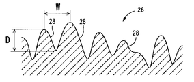
- FIG. 4 shows a cross section in the lens radial direction of the rear peripheral portion 26, which is a periodic cross section of the periodic structure formed by a plurality of minute grooves 28. Shown as a model. Note that the arrows in FIG. 3 indicate the lens circumferential direction.
- the rear peripheral portion 26 is preferably formed in an annular shape in a region of 2 mm or less in the lens radial direction from the outer peripheral edge of the optical unit 12, and a region within 3 mm in the lens radial direction from the center of the optical unit is It is preferable that the front central portion 20 is formed with no minute concave groove 28 formed thereon.
- the micro-groove 28 is a groove that opens to the outside of the lens, and the size thereof is smaller than that of the cell causing the subsequent cataract.
- the depth dimension: D is preferably set within a range of 0.01 ⁇ m ⁇ D ⁇ 1.0 ⁇ m
- the width dimension: W within a range of 0.1 ⁇ W ⁇ 2.0 ⁇ m.
- the minute concave groove 28 may be formed in an annular shape that continues over the entire circumference of the lens, but may be formed with a circumferential length dimension that does not continue over the entire circumference of the lens. It may be branched on the way. Accordingly, the circumferential length of the minute groove 28 is preferably set within a range of 1.0 ⁇ m to 50.0 ⁇ m.
- the minute groove 28 extending in the lens circumferential direction does not necessarily extend in a direction strictly coincident with the lens circumferential direction, and the lens is accompanied by some distortion. It extends with a circumferential component.
- a large number of such minute concave grooves 28 are formed directly on the surface of the rear peripheral portion 26 with appropriate intervals in the lens radial direction.
- a concave portion extending by a predetermined length in the circumferential direction of the lens surface is formed by the minute concave groove 28, and a convex portion extending by a predetermined length in the circumferential direction of the lens surface between the minute concave grooves 28.
- the surface of the rear peripheral portion 26 has linear micro unevenness having a periodic uneven shape in the lens radial direction with respect to the basic shape surface of the lens rear surface 18 that is a spherical convex surface. Directly formed.
- At least one minute concave groove 28 is formed at any position in the lens radial direction over the entire circumference of the rear peripheral portion 26.
- at least one minute concave groove 28 is formed in the rear peripheral portion 26 over the entire circumference.
- the plurality of minute concave grooves 28 are periodically arranged in the lens radial direction, so that the linear minute irregularities formed by the minute concave grooves 28 and the convex portions therebetween are the diameters of the rear peripheral portion 26.
- the cross-sectional shape in the lens radial direction is a sinusoidal curved shape as shown in model form in FIG. 4.
- concave portions by the minute grooves 28 and convex portions therebetween are alternately formed in the lens circumferential direction and the lens radial direction, and in the lens circumferential direction or the lens radial direction.
- Adjacent concave portions and convex portions are formed continuously with each other so that the basic shape surface of the lens rear surface 18 does not appear between the adjacent concave portions and convex portions.
- the linear minute irregularities are formed on the entire surface of the rear peripheral portion 26 without any gaps.
- the visible light transmittance of the rear peripheral portion 26 where the minute groove 28 is formed is ensured to be 60% or more.
- the outer peripheral surface 32 of the edge portion 30 that connects the lens front surface 16 and the lens rear surface 18 is also formed in the cell induction region in which the minute grooves 28 are formed. It is said that. Since the minute groove 28 formed on the outer peripheral surface 32 of the edge portion 30 has the same structure as the minute groove 28 formed on the rear peripheral portion 26, a detailed description thereof is omitted.
- the minute groove 28 formed in 30 is formed directly on the outer peripheral surface 32 of the edge portion 30 and is a groove that opens outward in the lens radial direction and extends over a predetermined dimension in the lens circumferential direction. .
- a plurality of such micro-grooves 28 are periodically formed in the lens thickness direction (vertical direction in FIG. 2), so that in the cross-section of the edge portion 30 in the lens thickness direction, The linear minute irregularities formed between them are formed with a sinusoidal curved cross section.
- the minute concave grooves 28 and the linear minute irregularities formed between them are formed on the entire outer peripheral surface 32 of the edge portion 30 without any gaps.
- the minute concave groove 28 is formed over the entire rear peripheral portion 26 constituting the outer peripheral portion of the lens rear surface 18 and the entire outer peripheral surface 32 of the edge portion 30.
- the rear surface peripheral portion 26 and the outer peripheral surface 32 of the edge portion 30 are cell induction regions.
- the intraocular lens 10 having such a structure is inserted into the sac through the incision of the capsular sac in a folded state by using an appropriate insertion instrument as necessary. Then, the intraocular lens 10 inserted into the sac expands so as to be restored to its initial state by its own elastic force, and the optical unit 12 is positioned and supported at a predetermined position in the sac by the pair of support parts 14, and the lens rear surface 18 is stored in the sac in a state of being brought into contact with the posterior sac.
- the lens circumferential direction extends over the entire rear peripheral portion 26 by the minute concave grooves 28 formed in the rear peripheral portion 26 and the convex portions therebetween.
- the linear minute unevenness extending in the direction is formed.
- the edge portion 30 can also induce the proliferation direction of the cause cell in the lens circumferential direction. In addition, it is possible to more effectively suppress the proliferation of the causative cells to the central portion of the lens.
- the rear peripheral portion 26 can also be used as an effective optical part, and the effective optical part diameter of the intraocular lens having a large restriction on the lens diameter to be housed in the sac is secured as much as possible. It can exhibit an excellent inhibitory effect on cataracts.
- only the rear peripheral portion 26 is a cell guiding region in which minute concave grooves 28 are formed on the front and rear surfaces 16 and 18 of the lens that affect optical characteristics. Since the minute concave groove 28 is not formed in the whole and the rear surface central portion 22, the influence on the optical characteristics is further reduced.
- a female mold 40 and a male mold 42 are prepared as molds.
- These male and female molds are a lens mold female mold 44 (see FIG. 6) and a lens mold male mold 46 (see FIG. 6) as resin molds for obtaining the target intraocular lens 10 by molding (polymerization). 6) are manufactured independently by a known resin molding method.
- the molding die brihard steel suitable for laser processing as will be described later is preferably employed, but any other metal material can be employed.
- thermoplastic resin materials used for the male and female molds 44 and 46 for molding lenses for example, polypropylene, polyethylene, polyethylene terephthalate, polystyrene, polycarbonate, vinyl chloride, nylon, polyacetal, fluororesin, etc. can be adopted. It is.
- the female mold 40 includes a first mold 50 having a concave resin mold molding surface 48 at the central portion and a second mold 54 having a convex resin mold molding surface 52 at the central portion. It is comprised including.
- the convex resin mold molding surface 52 of the second mold 54 is formed so as to include shapes corresponding to the lens rear surface 18 of the intraocular lens 10 and the outer peripheral surface 32 of the edge portion 30 at the central portion thereof. Yes.
- the resin mold molding surface 52 of the second mold 54 has a periodic structure of a large number of linear micro irregularities at positions corresponding to the rear surface peripheral portion 26 of the intraocular lens 10 and the outer peripheral surface 32 of the edge portion 30.
- a periodic structure transfer surface 55 is formed.
- a specific method for forming the periodic structure transfer surface 55 is not particularly limited.
- the periodic structure transfer surface 55 may be formed by cutting with a cutting tool or the like. A mode in which light is irradiated and processed in a non-contact state, lithography, or the like is employed.
- the laser beam has a pulse width of 1 ⁇ 10 ⁇ 16 seconds to 1 ⁇ 10 ⁇ 7 seconds, and more preferably a pulse width of 1 ⁇ 10 ⁇ 15 seconds to 1 ⁇ 10 ⁇ 9 seconds.
- the resin mold molding surface 52 is ablated to generate a periodic structure.
- the aspect which forms is employ
- the extending direction of the concave shape and the convex shape is the lens circumferential direction
- the periodic structure formed by the concave shape and the convex shape is the edge portion in the lens radial direction at a position corresponding to the rear surface peripheral portion 26. In the position corresponding to the outer peripheral surface 32 of 30, it forms in the thickness direction of a lens.
- the lens cavity female mold 44 is molded by injecting a thermoplastic resin material into the molding cavity 56 through a sprue or runner 58 and cooling and solidifying the molding cavity 56 with an injection device (not shown), for example.
- the lens molding surface 60 of the lens molding female mold 44 is formed by the resin mold molding surface 52 of the second mold 54, whereby the rear surface of the intraocular lens 10 including the lens rear surface 18 and the edge portion 30.
- the shape corresponding to the outer peripheral surface of the intraocular lens 10 including the outer peripheral surface 32 is set.
- the periodic structure of the periodic structure transfer surface 55 formed on the resin mold surface 52 of the female mold 40 Is transferred to the lens molding surface 60 of the female mold 44 for lens molding.
- the lens molding surface 60 of the lens molding female mold 40 has a large number of linear shapes in portions corresponding to the formation positions of the target rear surface peripheral portion 26 and the outer peripheral surface 32 of the edge portion 30 in the intraocular lens 10.
- a periodic structure molding surface 61 in which minute irregularities are formed is formed.
- the male mold 42 is a first mold 64 having a concave resin mold molding surface 62 in the central portion and a second mold having a convex resin mold molding surface 66 in the central portion.
- a mold 68 is included.
- the concave resin mold surface 62 of the first mold 64 is formed so as to include a shape corresponding to the lens front surface 16 of the intraocular lens 10 at the central portion thereof.
- the first and second molds 64 and 68 are closed in the axial direction by a mold clamping device (not shown), and a molding cavity 72 is formed between the mold mating surfaces of both the molds 64 and 68.
- the thermoplastic resin material is injected and filled into the molding cavity 72 through the runner 58 and cooled and solidified, the molded product made of the resin material is taken out by opening the molds 64 and 68.
- the male mold 46 for lens molding is obtained.
- the lens molding surface 74 of the lens molding male mold 46 is formed by the resin mold molding surface 62 of the second mold 64, so that the lens molding surface 74 of the lens molding male mold 46 becomes the lens front surface 16. It is set as the shape corresponding to the front surface of the intraocular lens 10 containing.
- the objective intraocular lens 10 is molded using the lens molding female mold 44 on which the periodic structure molding surface 61 is formed and the lens molding male mold 46.
- the lens molding female mold 44 is supported so as to open vertically upward, and the saucer-shaped region formed by the concave lens molding surface 60 is used as the material of the intraocular lens 10 as illustrated above.
- a polymerizable monomer 78 is added.
- the lens forming male mold 46 is overlapped in the axial direction (vertical direction in FIG. 6) from above and vertically fitted to the lens forming female mold 44, and the mold is adjusted.
- a polymerizable cavity 78 is filled to form a sealed molding cavity 80.
- the polymerization process of the polymerizable monomer 78 is performed while maintaining the mold matching state of both molds 44 and 46.
- photopolymerization or thermal polymerization is appropriately employed depending on the polymerizable monomer 78 to be employed.
- the lens mold female mold 44 and the lens mold male mold 46 are opened, and the intraocular lens made of the polymerized molded product is removed, so that the target eye is formed.
- the inner lens 10 is obtained.
- the linear minute irregularities of the periodic structure molding surface 61 formed on the lens molding surface 60 of the lens molding female die 44 are the outer peripheral surface of the rear surface peripheral portion 26 of the lens rear surface 18 and the edge portion 30 of the intraocular lens 10.
- the cell induction region is formed on the rear peripheral portion 26 and the outer peripheral surface 32 of the edge portion 30.
- the periodic structure of the linear fine irregularities formed on the female mold 40 is transferred to the intraocular lens 10 via the female mold 44, the intraocular lens is removed. Even when a large number of lenses are manufactured, it is possible to suppress variations in the shape of the linear fine irregularities in each lens. Further, if the periodic structure transfer surface 55 is formed on the female mold 40, it can be manufactured by the same process as that of the conventional mold forming method. Therefore, the number of man-hours on the intraocular lens production line is not substantially increased, and 10 intraocular lenses having linear fine irregularities can be obtained with excellent production efficiency.
- the periodic structure transfer surface 55 in the female mold 44 is formed in a non-contact state using ablation with femtosecond laser light. Therefore, since the processed surface is hardly heated, deformation due to heat is suppressed, and the periodic structure of linear fine irregularities can be formed with high accuracy and stability.
- the periodic structure transfer surface 55 on the female mold 44 in order to form the periodic structure transfer surface 55 on the female mold 44, it is possible to employ radiation instead of laser light. Can be suitably employed. Even with such an electron beam, the processed surface can be processed without heating by adjusting the irradiation energy.
- the cell induction region may be formed on any lens surface of the lens front surface, the lens rear surface, or the outer peripheral surface of the edge portion, or may be formed on the entire lens surface,
- the front peripheral portion 24 is also formed with micro concave grooves 28 to form a cell induction region, or the front and rear surface central portions 20, 22 are also used as cell induction regions.
- the outer peripheral surface 32 of the edge portion 30 may be used as a cell induction region.
- a cell induction region having a structure according to the present invention may be used in combination with a conventionally known sharp edge shape as shown in, for example, JP-T-2005-507742 and WO2004 / 096099. .
- the periodic structure molding surface 61 is formed by laser processing the lens molding female die 44 as a resin mold without laser processing the female molding die 40 as a mold. You may do it.
- the intraocular lens may be formed directly from the mold without passing through the resin mold. In that case, the linear minute unevenness formed on the mold is transferred to the lens surface as an inverted shape to form a cell suppression region. Moreover, even if it forms a linear micro unevenness
- a plate corresponding to an intraocular lens according to the present invention (periodic processing plate) provided with a periodic structure according to a manufacturing method according to the present invention, and a plate corresponding to an intraocular lens according to a conventional structure having no periodic structure (non-periodic) Processing plates) were prepared, and the cell growth directions on each plate were compared and examined.
- a machine structural carbon steel (S45C) plate mold is prepared, the polarization direction is parallel to the lens radial direction with respect to the surface of the plate mold, and a line is formed by a cylindrical lens.
- the shaped femtosecond laser was irradiated in parallel with the lens radial direction with the output as the processing threshold. Then, by rotating the plate mold, a circumferential fine periodic structure was formed on the plate mold.
- the femtosecond laser had a wavelength of 800 nm, a pulse width of 180 fs, and a repetition frequency of 1 kHz.
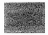
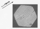
- FIG. 7 shows the surface of the fine periodic structure forming portion in the plate mold
- FIG. 8 shows the surface of the fine periodic structure non-forming portion in the plate mold.
- a nylon resin mold was formed by injection molding using a plate mold on which such a fine periodic structure was formed, and the fine periodic structure formed on the surface of the plate mold was transferred to the resin mold. Then, an acrylate-based material was polymerized and molded using a resin mold to which a fine periodic structure was transferred to obtain a periodic structure plate as an example having a diameter of 11 mm and a thickness of 1 mm.
- the non-periodic processing plate as a comparative example was formed by the same method as described above, using the mold plate without performing laser processing.
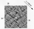
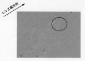
- FIG. 9 and 10 show the surface of the periodic processing plate and an enlarged image thereof
- FIG. 11 shows the surface of the non-periodic processing plate.
- 9 and 10 indicate the extending direction of the grooves forming the periodic structure.
- FIG. 10 is an enlarged view of a circled region in FIG.
- the major axis direction of each spindle shape of the grown cells is irregular, whereas the periodic processing having the periodic structure is performed.
- the major axis direction of each spindle shape of the grown cells is substantially coincident with the extending direction of the groove. From this, it was confirmed that according to the intraocular lens of the present invention, the cell proliferation direction can be guided in the groove extending direction, that is, the lens circumferential direction.
- a plate (periodic processing plate) corresponding to the intraocular lens according to the present invention and a plate (non-periodic processing plate) corresponding to the intraocular lens according to the conventional structure are prepared, and the visible light transmittance in each plate is prepared. It was measured.
- the periodic processing plate and the non-periodic processing plate are manufactured by the same method as the above manufacturing method except that STAVAX (trademark) plated with nickel is used as a plate mold and a silicon-containing water-containing material is used as a plate material. Obtained.
- FIG. 12 shows the measurement results of the light transmittance of the periodic processing plate and the non-periodic processing plate.
- the light transmittance was measured using an ultraviolet / visible spectrophotometer (trade name: UV-3150) manufactured by Shimadzu Corporation.
- the periodic processed plate corresponding to the intraocular lens according to the present invention has a high transmittance of 80% or more in the visible light region of 350 nm to 800 nm.
- a non-periodic processing plate corresponding to an intraocular lens according to a conventional structure there is almost no difference in the region of 400 nm to 550 nm or 700 nm or more, and the decrease in the other regions is only about 5% at maximum.
- the transmittance is almost the same as that of the conventional structure.
Abstract
Description
The present invention relates to an intraocular lens used in a state of being accommodated in a capsular bag, and more particularly to an intraocular lens that is effective in suppressing secondary cataract.
12 光学部
14 支持部
16 レンズ前面
18 レンズ後面
20 前面中央部
22 後面中央部
24 前面周辺部
26 後面周辺部
28 微小凹溝
30 エッジ部
32 外周面 DESCRIPTION OF
以下の如き、直鎖状,分岐鎖状又は環状のアルキル(メタ)アクリレート類;
メチル(メタ)アクリレート、エチル(メタ)アクリレート、ブチル(メタ)アクリレート、シクロヘキシル(メタ)アクリレート等
以下の如き、水酸基含有(メタ)アクリレート類;
ヒドロキシエチル(メタ)アクリレート、ヒドロキシブチル(メタ)アクリレート、ジエチレングリコールモノ(メタ)アクリレート等
以下の如き、芳香環含有(メタ)アクリレート類;
フェノキシエチル(メタ)アクリレート、フェニル(メタ)アクリレート、フェニルエチル(メタ)アクリレート等
以下の如き、シリコン含有(メタ)アクリレート類;
トリメチルシロキシジメチルシリルメチル(メタ)アクリレート、トリメチルシロキシジメチルシリルプロピル(メタ)アクリレート等
なお、「(メタ)アクリレート」とは、「・・・アクリレート」並びに「・・・メタクリレート」の二つの化合物を総称するものであり、後述するその他の(メタ)アクリル誘導体についても同様とする。 (I) Containing monomer The linear, branched or cyclic alkyl (meth) acrylates as follows:
Methyl (meth) acrylate, ethyl (meth) acrylate, butyl (meth) acrylate, cyclohexyl (meth) acrylate, etc. Hydroxyl group-containing (meth) acrylates as follows:
Hydroxyethyl (meth) acrylate, hydroxybutyl (meth) acrylate, diethylene glycol mono (meth) acrylate, etc. Aromatic ring-containing (meth) acrylates such as the following:
Phenoxyethyl (meth) acrylate, phenyl (meth) acrylate, phenylethyl (meth) acrylate, etc. Silicon-containing (meth) acrylates such as the following:
Trimethylsiloxydimethylsilylmethyl (meth) acrylate, trimethylsiloxydimethylsilylpropyl (meth) acrylate, etc. Note that “(meth) acrylate” is a generic term for the two compounds “... acrylate” and “... methacrylate”. The same applies to other (meth) acrylic derivatives described later.
以下の如き、(メタ)アクリルアミドまたはその誘導体;
(メタ)アクリルアミド、N,N-ジメチル(メタ)アクリルアミド等
以下の如き、N-ビニルラクタム類;
N-ビニルピロリドン等
スチレンまたはその誘導体
以下の如き、架橋性モノマー;
ブタンジオールジ(メタ)アクリレート、エチレングリコールジ(メタ)アクリレート (Ii) Arbitrary monomer (Meth) acrylamide or a derivative thereof as follows:
(Meth) acrylamide, N, N-dimethyl (meth) acrylamide, etc. N-vinyl lactams such as the following:
N-vinylpyrrolidone, etc. Styrene or its derivatives Crosslinkable monomers such as:
Butanediol di (meth) acrylate, ethylene glycol di (meth) acrylate
熱重合開始剤、光重合開始剤、光増感剤等
色素等
紫外線吸収剤等 (Iii) Additive Thermal polymerization initiator, photopolymerization initiator, photosensitizer, etc. Pigment, etc. Ultraviolet absorber, etc.
1.細胞(V79細胞:チャイニーズハムスター肺由来線維芽細胞(JCRB0603))がフラスコの培養面で略60%~80%コンフルエントに達したのを確認後、PBS(-)洗浄した。次に、トリプシン溶液によって細胞を剥離し、培養液(10vol%牛胎仔血清添加MEM培地(MEM10倍地))を加えて細胞浮遊液を調製した。かかる細胞浮遊液をトリパンブルー溶液およびPBS(-)混合液に加えて、血球計算盤を用いて細胞数を計数した。更に、培養液で希釈して、略5×10³ cell/mLの細胞浮遊液を調製した。
2.周期加工プレートおよび非周期加工プレートをそれぞれウェルの底面に設置し、それぞれのウェルに対して培養液を0.5mLずつ分注後、上記1で得た細胞浮遊液を0.1mLずつ播種することによって、1ウェルあたり略500個の細胞を播種し、炭酸ガス培養装置内で培養した。
3.播種から3日後に細胞をホルマリン固定し、固定後、蒸留水で数回洗浄して自然風乾した。
4.上記1~3によって得られた周期加工プレートおよび非周期加工プレートを微分干渉顕微鏡にて観察した。 And the test was done in the procedure shown below with respect to these periodic processing plate and non-periodic processing plate.
1. After confirming that the cells (V79 cells: Chinese hamster lung-derived fibroblasts (JCRB0603)) reached approximately 60% to 80% confluence on the culture surface of the flask, the cells were washed with PBS (−). Next, the cells were detached using a trypsin solution, and a culture solution (MEM medium supplemented with 10 vol% fetal calf serum (
2. Place a periodic processing plate and a non-periodic processing plate on the bottom of each well, dispense 0.5 mL of culture solution to each well, and then inoculate 0.1 mL of the cell suspension obtained in 1 above. Thus, approximately 500 cells were seeded per well and cultured in a carbon dioxide culture apparatus.
3. Three days after seeding, the cells were fixed in formalin, fixed, washed several times with distilled water, and air-dried.
4). The periodic processed plate and the aperiodic processed plate obtained by the above 1 to 3 were observed with a differential interference microscope.
Claims (10)
- 水晶体嚢への収納状態で用いられる眼内レンズであって、
レンズ表面の少なくとも一部を多数の微小凹凸が直接に形成された細胞誘導領域として、該微小凹凸を0.01~1.0μmの深さ寸法と0.1~2.0μmの幅寸法をもって該レンズ表面の周方向に所定長さで延びる線状微小凹凸とすると共に、該線状微小凹凸を該レンズ表面の周方向で連なった連鎖構造で且つ該レンズ表面の周方向に直交する方向で周期的に配列した周期構造とすることにより、該細胞誘導領域の全体に亘って該線状微小凹凸を隙間無く形成せしめて該細胞誘導領域における可視光線透過率を60%以上としたことを特徴とする眼内レンズ。 An intraocular lens used in a stored state in a capsular bag,
Using at least a part of the lens surface as a cell induction region in which a large number of minute irregularities are directly formed, the minute irregularities have a depth dimension of 0.01 to 1.0 μm and a width dimension of 0.1 to 2.0 μm. The linear micro unevenness extending in the circumferential direction of the lens surface with a predetermined length is a chain structure in which the linear micro unevenness is continuous in the circumferential direction of the lens surface, and the period is perpendicular to the circumferential direction of the lens surface. By forming a periodic structure arranged periodically, the linear micro unevenness is formed without gaps over the entire cell induction region, and the visible light transmittance in the cell induction region is 60% or more. Intraocular lens. - 前記線状微細凹凸の周方向長さ寸法が1.0~50.0μmとされている請求項1に記載の眼内レンズ。 The intraocular lens according to claim 1, wherein a circumferential length dimension of the linear fine irregularities is 1.0 to 50.0 μm.
- 前記細胞誘導領域が、レンズ前面とレンズ後面の少なくとも一方の外周部分に形成されている請求項1又は2に記載の眼内レンズ。 The intraocular lens according to claim 1 or 2, wherein the cell induction region is formed on an outer peripheral portion of at least one of a lens front surface and a lens rear surface.
- 前記細胞誘導領域が、前記レンズ前面と前記レンズ後面の少なくとも一方の中央部分を除く外周部分だけに形成されている請求項3に記載の眼内レンズ。 The intraocular lens according to claim 3, wherein the cell guiding region is formed only on an outer peripheral portion excluding a central portion of at least one of the front surface of the lens and the rear surface of the lens.
- 前記レンズ前面と前記レンズ後面の少なくとも一方の外周部分だけに形成された前記細胞誘導領域が、レンズ外周端からレンズ径方向に2mm以下の領域とされている請求項4に記載の眼内レンズ。 The intraocular lens according to claim 4, wherein the cell induction region formed only in the outer peripheral portion of at least one of the lens front surface and the lens rear surface is a region of 2 mm or less from the lens outer peripheral end in the lens radial direction.
- 前記線状微小凹凸が、レンズ外周端面を含むエッジ部の表面に形成されており、該エッジ部の表面を含んで前記細胞誘導領域とされている請求項1乃至5の何れか一項に記載の眼内レンズ。 6. The linear micro unevenness is formed on a surface of an edge part including a lens outer peripheral end surface, and includes the surface of the edge part as the cell induction region. Intraocular lens.
- 前記細胞誘導領域のレンズ周方向に直交する方向の断面において、前記線状微小凹凸が略周期関数で表される周期的な断面形状をもって形成されている請求項1乃至6の何れか一項に記載の眼内レンズ。 The cross section of the cell induction region in a direction orthogonal to the lens circumferential direction has the linear micro unevenness formed with a periodic cross-sectional shape represented by a substantially periodic function. The intraocular lens described.
- 線状微小凹凸が成形面に形成された金型によって成形されて該線状微小凹凸が転写された樹脂型を用いて前記レンズ表面の少なくとも一つが形成されて、該樹脂型における線状微小凹凸が該レンズ表面に転写されることによって前記細胞誘導領域が形成されている請求項1乃至7の何れか一項に記載の眼内レンズ。 At least one of the lens surfaces is formed by using a resin mold in which linear micro unevenness is molded by a mold formed on a molding surface and the linear micro unevenness is transferred, and linear micro unevenness in the resin mold is formed. The intraocular lens according to any one of claims 1 to 7, wherein the cell induction region is formed by being transferred to the lens surface.
- 水晶体嚢への収納状態で用いられる眼内レンズの製造方法であって、
金型によって成形した樹脂型を用いてレンズ表面の少なくとも一つを形成すると共に、該金型における樹脂型成形面に対して放射線及びレーザー光の少なくとも一方を照射することによって微小凹凸を形成して、該金型に形成された該微小凹凸を該樹脂型のレンズ成形面に転写し、この樹脂型に転写形成された該微小凹凸構造を該レンズ表面の少なくとも一つに再転写することによって、該レンズ表面の少なくとも一部において多数の微小凹凸が直接に形成された細胞誘導領域を形成するに際して、該微小凹凸を0.01~1.0μmの深さ寸法と0.1~2.0μmの幅寸法をもって該レンズ表面の周方向に所定長さで延びる線状微小凹凸として形成すると共に、該線状微小凹凸を該レンズ表面の周方向で連なった連鎖構造で且つ該レンズ表面の周方向に直交する方向で周期的に配列した周期構造とすることにより、該細胞誘導領域の全体に亘って該線状微小凹凸を隙間なく形成せしめて該細胞誘導領域における可視光線透過率を60%以上に設定することを特徴とする眼内レンズの製造方法。 A method for producing an intraocular lens used in a stored state in a lens capsule,
Forming at least one of the lens surfaces using a resin mold molded by a mold, and forming minute irregularities by irradiating at least one of radiation and laser light to the resin mold molding surface of the mold By transferring the micro unevenness formed on the mold to the lens molding surface of the resin mold, and retransferring the micro uneven structure transferred and formed on the resin mold to at least one of the lens surfaces, When forming a cell induction region in which a large number of minute irregularities are directly formed on at least a part of the lens surface, the minute irregularities are formed with a depth of 0.01 to 1.0 μm and a depth of 0.1 to 2.0 μm. It is formed as a linear micro unevenness having a width dimension extending in a circumferential direction on the lens surface with a predetermined length, and has a chain structure in which the linear micro unevenness is continuous in the circumferential direction of the lens surface and the lens surface. By forming a periodic structure periodically arranged in a direction orthogonal to the circumferential direction of the surface, the linear minute irregularities are formed without gaps throughout the cell induction region, and the visible light transmittance in the cell induction region Is set to 60% or more, and a method for manufacturing an intraocular lens. - 前記レーザー光として、パルス幅が1×10-16 秒~1×10⁻⁷秒とされるレーザー光を用いる請求項9に記載の眼内レンズの製造方法。 10. The method of manufacturing an intraocular lens according to claim 9, wherein a laser beam having a pulse width of 1 × 10 −16 seconds to 1 × 10 −7 seconds is used as the laser light.
Priority Applications (6)
| Application Number | Priority Date | Filing Date | Title |
|---|---|---|---|
| CN2008801303517A CN102088929A (en) | 2008-07-15 | 2008-07-15 | Intraocular lens and its manufacturing method |
| KR1020117000957A KR101257675B1 (en) | 2008-07-15 | 2008-07-15 | Intraocular lens and its manufacturing method |
| JP2010502386A JP4527201B2 (en) | 2008-07-15 | 2008-07-15 | Intraocular lens and manufacturing method thereof |
| EP08790203.7A EP2305178B1 (en) | 2008-07-15 | 2008-07-15 | Intraocular lens and its manufacturing method |
| US13/001,484 US8337552B2 (en) | 2008-07-15 | 2008-07-15 | Intraocular lens and manufacturing method thereof |
| PCT/JP2008/001901 WO2010007646A1 (en) | 2008-07-15 | 2008-07-15 | Intraocular lens and its manufacturing method |
Applications Claiming Priority (1)
| Application Number | Priority Date | Filing Date | Title |
|---|---|---|---|
| PCT/JP2008/001901 WO2010007646A1 (en) | 2008-07-15 | 2008-07-15 | Intraocular lens and its manufacturing method |
Publications (1)
| Publication Number | Publication Date |
|---|---|
| WO2010007646A1 true WO2010007646A1 (en) | 2010-01-21 |
Family
ID=41550066
Family Applications (1)
| Application Number | Title | Priority Date | Filing Date |
|---|---|---|---|
| PCT/JP2008/001901 WO2010007646A1 (en) | 2008-07-15 | 2008-07-15 | Intraocular lens and its manufacturing method |
Country Status (6)
| Country | Link |
|---|---|
| US (1) | US8337552B2 (en) |
| EP (1) | EP2305178B1 (en) |
| JP (1) | JP4527201B2 (en) |
| KR (1) | KR101257675B1 (en) |
| CN (1) | CN102088929A (en) |
| WO (1) | WO2010007646A1 (en) |
Cited By (2)
| Publication number | Priority date | Publication date | Assignee | Title |
|---|---|---|---|---|
| JP2017523022A (en) * | 2014-08-07 | 2017-08-17 | インサイト イノベーションズ, エルエルシー | Micropatterned intraocular implant |
| JP2020503542A (en) * | 2016-12-13 | 2020-01-30 | アイクスレンズ ゲーエムベーハー | Manufacturing method of transmission optical system |
Families Citing this family (19)
| Publication number | Priority date | Publication date | Assignee | Title |
|---|---|---|---|---|
| US9089419B2 (en) * | 2008-10-15 | 2015-07-28 | Novartis Ag | System to reduce surface contact between optic and haptic areas |
| US9943402B2 (en) | 2008-11-20 | 2018-04-17 | Insight Innovations, Llc | Micropatterned intraocular implant |
| US20120232649A1 (en) | 2008-11-20 | 2012-09-13 | Insight Innovations, Llc | Intraocular Lens Cell Migration Inhibition System |
| WO2010059214A2 (en) | 2008-11-20 | 2010-05-27 | Insight Innovations, Llc | Biocompatible biodegradable intraocular implant system |
| US8551167B2 (en) | 2008-11-20 | 2013-10-08 | Insight Innovations, Llc | Intraocular implant cell migration inhibition system |
| US8444673B2 (en) | 2010-02-11 | 2013-05-21 | Boston Scientific Scimed, Inc. | Automatic vascular closure deployment devices and methods |
| WO2013176982A1 (en) * | 2012-05-23 | 2013-11-28 | Insight Innovations, Llc | Intraocular lens cell migration inhibition system |
| CN105050784B (en) * | 2013-03-27 | 2018-05-04 | 富士胶片株式会社 | Optical lens, lens unit, the manufacture method of photographing module and optical lens |
| NL2011239C2 (en) | 2013-07-30 | 2015-02-02 | Innovalens B V | INSERTS COMPOSITION FOR MANUFACTURE OF INTRA-OCULAR LENSES. |
| US10299910B2 (en) | 2014-09-22 | 2019-05-28 | Kevin J. Cady | Intraocular pseudophakic contact lens with mechanism for securing by anterior leaflet of capsular wall and related system and method |
| US10945832B2 (en) | 2014-09-22 | 2021-03-16 | Onpoint Vision, Inc. | Intraocular pseudophakic contact lens with mechanism for securing by anterior leaflet of capsular wall and related system and method |
| US10159562B2 (en) | 2014-09-22 | 2018-12-25 | Kevin J. Cady | Intraocular pseudophakic contact lenses and related systems and methods |
| US11109957B2 (en) | 2014-09-22 | 2021-09-07 | Onpoint Vision, Inc. | Intraocular pseudophakic contact lens with mechanism for securing by anterior leaflet of capsular wall and related system and method |
| US11938018B2 (en) | 2014-09-22 | 2024-03-26 | Onpoint Vision, Inc. | Intraocular pseudophakic contact lens (IOPCL) for treating age-related macular degeneration (AMD) or other eye disorders |
| KR101629199B1 (en) * | 2014-10-06 | 2016-06-10 | 한국과학기술연구원 | Intraocular lens with fine pattern |
| CN106466203B (en) * | 2015-08-14 | 2020-04-03 | 爱博诺德(苏州)医疗器械有限公司 | Intraocular implant with stress deformation texture structure |
| CN106901871B (en) * | 2015-12-23 | 2021-08-24 | 爱博诺德(北京)医疗科技股份有限公司 | Intraocular lens with one or more additional portions |
| KR102252688B1 (en) * | 2018-07-16 | 2021-05-17 | 한국과학기술연구원 | Intraocular lens and method of manufacturing the same |
| KR102559052B1 (en) * | 2020-06-04 | 2023-07-21 | 최병찬 | Intraocular lens |
Citations (7)
| Publication number | Priority date | Publication date | Assignee | Title |
|---|---|---|---|---|
| US4449257A (en) * | 1982-05-03 | 1984-05-22 | Barnes-Hind/Hydrocurve, Inc. | Intraocular lens and method of retaining in place |
| US5405385A (en) * | 1992-04-02 | 1995-04-11 | Clemson University | Intraocular lens with integrated means of fixation |
| JPH1024097A (en) | 1996-07-11 | 1998-01-27 | Menicon Co Ltd | Lens for soft eye and its manufacture |
| JPH1156998A (en) | 1997-08-20 | 1999-03-02 | Menicon Co Ltd | Material for soft inside eye lens |
| JPH11505453A (en) | 1995-05-09 | 1999-05-21 | アラーガン | Intraocular lens for reducing secondary opacity |
| WO2004096099A1 (en) | 2003-04-28 | 2004-11-11 | Hoya Healthcare Corporation | Single piece intraocular lens and method for producing same |
| JP2005507742A (en) | 2001-11-08 | 2005-03-24 | ボシュ・アンド・ロム・インコーポレイテッド | Intraocular lens |
Family Cites Families (2)
| Publication number | Priority date | Publication date | Assignee | Title |
|---|---|---|---|---|
| US5549670A (en) * | 1995-05-09 | 1996-08-27 | Allergan, Inc. | IOL for reducing secondary opacification |
| US20080077238A1 (en) * | 2006-09-21 | 2008-03-27 | Advanced Medical Optics, Inc. | Intraocular lenses for managing glare, adhesion, and cell migration |
-
2008
- 2008-07-15 JP JP2010502386A patent/JP4527201B2/en not_active Expired - Fee Related
- 2008-07-15 KR KR1020117000957A patent/KR101257675B1/en not_active IP Right Cessation
- 2008-07-15 CN CN2008801303517A patent/CN102088929A/en active Pending
- 2008-07-15 WO PCT/JP2008/001901 patent/WO2010007646A1/en active Application Filing
- 2008-07-15 EP EP08790203.7A patent/EP2305178B1/en not_active Not-in-force
- 2008-07-15 US US13/001,484 patent/US8337552B2/en not_active Expired - Fee Related
Patent Citations (7)
| Publication number | Priority date | Publication date | Assignee | Title |
|---|---|---|---|---|
| US4449257A (en) * | 1982-05-03 | 1984-05-22 | Barnes-Hind/Hydrocurve, Inc. | Intraocular lens and method of retaining in place |
| US5405385A (en) * | 1992-04-02 | 1995-04-11 | Clemson University | Intraocular lens with integrated means of fixation |
| JPH11505453A (en) | 1995-05-09 | 1999-05-21 | アラーガン | Intraocular lens for reducing secondary opacity |
| JPH1024097A (en) | 1996-07-11 | 1998-01-27 | Menicon Co Ltd | Lens for soft eye and its manufacture |
| JPH1156998A (en) | 1997-08-20 | 1999-03-02 | Menicon Co Ltd | Material for soft inside eye lens |
| JP2005507742A (en) | 2001-11-08 | 2005-03-24 | ボシュ・アンド・ロム・インコーポレイテッド | Intraocular lens |
| WO2004096099A1 (en) | 2003-04-28 | 2004-11-11 | Hoya Healthcare Corporation | Single piece intraocular lens and method for producing same |
Non-Patent Citations (1)
| Title |
|---|
| See also references of EP2305178A4 |
Cited By (3)
| Publication number | Priority date | Publication date | Assignee | Title |
|---|---|---|---|---|
| JP2017523022A (en) * | 2014-08-07 | 2017-08-17 | インサイト イノベーションズ, エルエルシー | Micropatterned intraocular implant |
| JP2020503542A (en) * | 2016-12-13 | 2020-01-30 | アイクスレンズ ゲーエムベーハー | Manufacturing method of transmission optical system |
| JP7235656B2 (en) | 2016-12-13 | 2023-03-08 | アイクスレンズ ゲーエムベーハー | Manufacturing method of transmissive optical system |
Also Published As
| Publication number | Publication date |
|---|---|
| US8337552B2 (en) | 2012-12-25 |
| JPWO2010007646A1 (en) | 2012-01-05 |
| CN102088929A (en) | 2011-06-08 |
| KR20110020300A (en) | 2011-03-02 |
| EP2305178A1 (en) | 2011-04-06 |
| EP2305178B1 (en) | 2014-03-12 |
| JP4527201B2 (en) | 2010-08-18 |
| KR101257675B1 (en) | 2013-04-24 |
| EP2305178A4 (en) | 2013-01-02 |
| US20110098808A1 (en) | 2011-04-28 |
Similar Documents
| Publication | Publication Date | Title |
|---|---|---|
| JP4527201B2 (en) | Intraocular lens and manufacturing method thereof | |
| JP6345773B2 (en) | Implantable myopia lens | |
| EP1781461B1 (en) | Using higher order mathematical functions to create asymmetric molding back pieces | |
| JP5149202B2 (en) | Contact lens manufacturing method | |
| US9421089B2 (en) | Intraocular lens with post-implantation adjustment capabilities | |
| US10390939B2 (en) | Micro-incision IOL and positioning of the IOL in the eye | |
| RU2009102971A (en) | METHOD FOR CONSTRUCTING AN IMPLANT OF AN IN-EYE LENS FOR CORRECTING ASTIGMATISM CAUSED BY SURGICAL OPERATION | |
| JP2007513715A (en) | Foldable intraocular lens and manufacturing method thereof | |
| CA2673829A1 (en) | Haptic for accommodating intraocular lens | |
| JP2011507628A5 (en) | ||
| CN101180009A (en) | Artificial crystal | |
| TW201207463A (en) | Surface enhanced ophthalmic lens | |
| WO2011109039A1 (en) | System for forming and modifying lenses and lenses formed thereby | |
| JP3798147B2 (en) | Ophthalmic lens mold | |
| CN114402251A (en) | System and method for forming an ophthalmic lens comprising a superstructural optic | |
| JP2008191344A (en) | Method for manufacturing contact lens with mark, and contact lens with mark | |
| US20130103144A1 (en) | System for forming and modifying lenses and lenses formed thereby | |
| US20150134059A1 (en) | Deformable accommodative intraocular lens | |
| JP6257070B2 (en) | Intraocular lens | |
| US20220378540A1 (en) | Method and apparatus for providing sterile cover for non-contact fundus viewing device | |
| WO2023001756A1 (en) | Composite mold insert for fabricating microstructured lenses | |
| JP2015051069A (en) | Intraocular lens and manufacturing method of intraocular lens | |
| JP2013052538A (en) | Method of manufacturing lens integrated with support part, blade mold used in the same, and lens integrated with support part | |
| CN117693424A (en) | Low thermal conductivity metal insert with surface microstructure | |
| JPS6391230A (en) | Manufacture of intraocular lens |
Legal Events
| Date | Code | Title | Description |
|---|---|---|---|
| WWE | Wipo information: entry into national phase |
Ref document number: 200880130351.7 Country of ref document: CN |
|
| ENP | Entry into the national phase |
Ref document number: 2010502386 Country of ref document: JP Kind code of ref document: A |
|
| 121 | Ep: the epo has been informed by wipo that ep was designated in this application |
Ref document number: 08790203 Country of ref document: EP Kind code of ref document: A1 |
|
| WWE | Wipo information: entry into national phase |
Ref document number: 13001484 Country of ref document: US |
|
| WWE | Wipo information: entry into national phase |
Ref document number: 2008790203 Country of ref document: EP |
|
| ENP | Entry into the national phase |
Ref document number: 20117000957 Country of ref document: KR Kind code of ref document: A |
|
| NENP | Non-entry into the national phase |
Ref country code: DE |