WO2009153929A1 - Optical image measuring device - Google Patents
Optical image measuring device Download PDFInfo
- Publication number
- WO2009153929A1 WO2009153929A1 PCT/JP2009/002565 JP2009002565W WO2009153929A1 WO 2009153929 A1 WO2009153929 A1 WO 2009153929A1 JP 2009002565 W JP2009002565 W JP 2009002565W WO 2009153929 A1 WO2009153929 A1 WO 2009153929A1
- Authority
- WO
- WIPO (PCT)
- Prior art keywords
- optical
- light
- image
- eye
- distance
- Prior art date
Links
Images


Classifications
-
- A—HUMAN NECESSITIES
- A61—MEDICAL OR VETERINARY SCIENCE; HYGIENE
- A61B—DIAGNOSIS; SURGERY; IDENTIFICATION
- A61B3/00—Apparatus for testing the eyes; Instruments for examining the eyes
- A61B3/10—Objective types, i.e. instruments for examining the eyes independent of the patients' perceptions or reactions
- A61B3/1005—Objective types, i.e. instruments for examining the eyes independent of the patients' perceptions or reactions for measuring distances inside the eye, e.g. thickness of the cornea
-
- A—HUMAN NECESSITIES
- A61—MEDICAL OR VETERINARY SCIENCE; HYGIENE
- A61B—DIAGNOSIS; SURGERY; IDENTIFICATION
- A61B3/00—Apparatus for testing the eyes; Instruments for examining the eyes
- A61B3/10—Objective types, i.e. instruments for examining the eyes independent of the patients' perceptions or reactions
- A61B3/102—Objective types, i.e. instruments for examining the eyes independent of the patients' perceptions or reactions for optical coherence tomography [OCT]
-
- G—PHYSICS
- G01—MEASURING; TESTING
- G01B—MEASURING LENGTH, THICKNESS OR SIMILAR LINEAR DIMENSIONS; MEASURING ANGLES; MEASURING AREAS; MEASURING IRREGULARITIES OF SURFACES OR CONTOURS
- G01B9/00—Measuring instruments characterised by the use of optical techniques
- G01B9/02—Interferometers
- G01B9/02083—Interferometers characterised by particular signal processing and presentation
- G01B9/02085—Combining two or more images of different regions
-
- G—PHYSICS
- G01—MEASURING; TESTING
- G01B—MEASURING LENGTH, THICKNESS OR SIMILAR LINEAR DIMENSIONS; MEASURING ANGLES; MEASURING AREAS; MEASURING IRREGULARITIES OF SURFACES OR CONTOURS
- G01B11/00—Measuring arrangements characterised by the use of optical techniques
- G01B11/24—Measuring arrangements characterised by the use of optical techniques for measuring contours or curvatures
- G01B11/2441—Measuring arrangements characterised by the use of optical techniques for measuring contours or curvatures using interferometry
-
- G—PHYSICS
- G01—MEASURING; TESTING
- G01B—MEASURING LENGTH, THICKNESS OR SIMILAR LINEAR DIMENSIONS; MEASURING ANGLES; MEASURING AREAS; MEASURING IRREGULARITIES OF SURFACES OR CONTOURS
- G01B9/00—Measuring instruments characterised by the use of optical techniques
- G01B9/02—Interferometers
- G01B9/02015—Interferometers characterised by the beam path configuration
- G01B9/02027—Two or more interferometric channels or interferometers
- G01B9/02028—Two or more reference or object arms in one interferometer
-
- G—PHYSICS
- G01—MEASURING; TESTING
- G01B—MEASURING LENGTH, THICKNESS OR SIMILAR LINEAR DIMENSIONS; MEASURING ANGLES; MEASURING AREAS; MEASURING IRREGULARITIES OF SURFACES OR CONTOURS
- G01B9/00—Measuring instruments characterised by the use of optical techniques
- G01B9/02—Interferometers
- G01B9/0209—Low-coherence interferometers
- G01B9/02091—Tomographic interferometers, e.g. based on optical coherence
Definitions
- the present invention relates to an optical image measurement device that forms an image representing a surface form or an internal form of an object to be measured using a light beam.
- optical image measurement technique that forms an image representing the surface form or internal form of an object to be measured using a light beam from a laser light source or the like has attracted attention. Since the optical image measurement technique does not have invasiveness to the human body unlike the X-ray CT apparatus, the development of application in the medical field and the biological field is particularly expected.
- Patent Document 1 discloses an apparatus to which an optical image measurement technique is applied.
- the measuring arm scans an object with a rotary turning mirror (galvanomirror), a reference mirror is installed on the reference arm, and the intensity of the interference light of the light beam from the measuring arm and the reference arm is dispersed at the exit.
- An interferometer is provided for analysis by the instrument.
- the reference arm is configured to change the phase of the reference light beam stepwise by a discontinuous value.
- Patent Document 1 uses a so-called “Fourier Domain OCT (Fourier Domain Optical Coherence Tomography)” technique.
- a low-coherence beam is irradiated onto the object to be measured, the reflected light and the reference light are superimposed to generate interference light, and the spectral intensity distribution of the interference light is acquired and subjected to Fourier transform.
- the form of the object to be measured in the depth direction (z direction) is imaged.
- the apparatus described in Patent Document 1 includes a galvanometer mirror that scans a light beam (signal light), thereby forming an image of a desired measurement target region of the object to be measured. Since this apparatus is configured to scan the light beam only in one direction (x direction) orthogonal to the z direction, the image formed by this apparatus is in the scanning direction (x direction) of the light beam. It becomes a two-dimensional tomographic image in the depth direction (z direction) along.
- Patent Document 2 a plurality of horizontal two-dimensional tomographic images are formed by scanning signal light in the horizontal direction and the vertical direction, and three-dimensional tomographic information of a measurement range is acquired based on the plurality of tomographic images.
- a technique for imaging is disclosed. Examples of the three-dimensional imaging include a method of displaying a plurality of tomographic images side by side in a vertical direction (referred to as stack data), and a method of rendering a plurality of tomographic images to form a three-dimensional image. Conceivable.
- Patent Documents 3 and 4 disclose other types of optical image measurement devices.
- Patent Document 3 scans the wavelength of light applied to an object to be measured, acquires a spectral intensity distribution based on interference light obtained by superimposing reflected light of each wavelength and reference light,
- an optical image measurement device that images the form of an object to be measured by performing Fourier transform on the object.
- Such an optical image measurement device is called a swept source type.
- the traveling direction of light is obtained by irradiating the object to be measured with light having a predetermined beam diameter, and analyzing the component of interference light obtained by superimposing the reflected light and the reference light.
- an optical image measurement device that forms an image of an object to be measured in a cross section orthogonal to the above.
- Such an optical image measuring device is called a full-field type or an en-face type.
- Patent Document 5 discloses a configuration in which the OCT technique is applied to the ophthalmic field. Prior to the application of the optical image measurement device to the ophthalmology field, an ophthalmologic photographing device such as a fundus camera was used (see, for example, Patent Document 6).
- the fundus imaging apparatus using the OCT technique has an advantage that a tomographic image and a three-dimensional image of the fundus can be acquired as compared with a fundus camera that only images the fundus from the front. Therefore, it is expected to contribute to improvement of diagnostic accuracy and early detection of lesions.
- An image (OCT image: tomographic image, three-dimensional image, etc.) acquired by an optical image measurement device is used for measuring various physical quantities of an object to be measured (or a part thereof). For example, in the field of ophthalmology, it is used to measure physical quantities such as the size and corners of a lesion.
- the conventional optical image measurement device can measure the physical quantity of the object depicted in one OCT image, but measures the physical quantity of the object depicted across multiple OCT images with high accuracy. It is difficult to do.
- the distance between two points in one OCT image could be measured, but one point in the first OCT image and one point in the second OCT image. It was difficult to measure the distance between them with high accuracy. In particular, for a measured object that is not in a stationary state, such as a living eye, there is a high possibility that the measurement accuracy will be reduced because the acquisition timing of the first OCT image and the second OCT image is shifted.
- the present invention has been made to solve such a problem, and its object is to measure a physical quantity of a measured object with high accuracy based on a plurality of OCT images depicting different parts of the measured object.
- the object is to provide an optical image measuring device.
- the invention described in claim 1 divides low-coherence light into signal light and reference light, and divides the optical path of the reference light into a plurality of optical paths having different optical path lengths.
- the reference light is divided into a plurality of reference lights, and the plurality of reference lights respectively passing through the plurality of optical paths are caused to interfere with the signal light passing through the object to be measured, so that a plurality of depth positions of the object to be measured are obtained.
- An optical system that generates interference light reflecting the form in each, detection means that detects the generated interference light and generates a detection signal, and at the plurality of depth positions based on the generated detection signal
- image forming means for forming a plurality of tomographic images each representing a form of the object to be measured, and an analyzing means for analyzing the plurality of tomographic images to obtain a predetermined physical quantity of the object to be measured.
- the invention according to claim 2 is the optical image measurement device according to claim 1, wherein the optical system splits the reference light divided from the low-coherence light into the plurality of reference lights.
- the interference light is generated by causing the plurality of combined reference lights to interfere with the signal light.
- the invention according to claim 3 is the optical image measuring device according to claim 1, wherein the optical system extends an optical path length of a part of the reference light divided from the low coherence light. And a reference mirror that reflects a part of the reference light whose optical path length is extended by the optical member and another part of the reference light, and the reference light reflected by the reference mirror is converted into the signal light. And generating the interference light.
- the invention according to claim 4 is the optical image measurement device according to claim 1, wherein the analysis unit includes the predetermined physical quantity in one tomographic image of the plurality of tomographic images. A distance between the position and a position in another tomographic image is obtained.
- the invention according to claim 5 is the optical image measurement device according to claim 4, wherein the object to be measured is a living eye, and the plurality of reference lights correspond to a retina of the living eye.
- a first reference light passing through a first optical path having an optical path length; and a second reference light passing through a second optical path having an optical path length corresponding to the cornea of the living eye. Extracts a first signal component corresponding to an interference component between the first reference light and the signal light reflected by the retina from the detection signal, and obtains a first tomographic image representing the form of the retina.
- a second signal component formed as the one tomographic image and corresponding to an interference component between the second reference light and the signal light reflected by the cornea is extracted from the detection signal, and Forming a second tomographic image representing a form as the other tomographic image, and performing the analysis Stage, by analyzing the first and said second tomographic image, obtains the corneal retinal distance between the living eye, characterized in that.
- the invention according to claim 6 is the optical image measurement device according to claim 5, wherein the first optical path and the second optical path are substantially equal to a standard value of a corneal-retinal distance.
- the analyzing means divides the standard value by the refractive index value of the eyeball optical system included in the eyeball optical information stored in advance, and calculates the quotient value and the first and second values.
- the intercorneal retina distance is obtained based on a tomographic image.
- the invention according to claim 7 is the optical image measurement device according to claim 5, wherein the analysis unit uses the living eye as the predetermined physical quantity based on the calculated intercorneal retinal distance.
- Magnification calculating means for determining the magnification of the eyeball optical system is included.
- the invention according to claim 8 is the optical image measurement device according to claim 7, wherein the magnification calculation means includes optical information of an eyeball optical system included in eyeball optical information stored in advance, and The magnification is obtained based on the obtained intercorneal retina distance.
- the invention according to claim 9 is the optical image measurement device according to claim 8, wherein the eyeball optical information includes the respective radii of curvature of the front and back surfaces of the cornea, the thickness of the cornea, and the refractive index of the cornea.
- the magnification calculation means subtracts the value of the anterior segment distance from the corneal interretinal distance to calculate a posterior segment distance representing a distance between the posterior surface of the lens and the retinal surface;
- An eyeball model is formed based on the posterior eye distance, and the magnification is obtained based on the eyeball model.
- the invention according to claim 10 is the optical image measurement device according to claim 9, further comprising alignment means for aligning the optical system with respect to the living eye, wherein the analysis means includes A position in the frame of the second tomographic image based on the interference light generated by the optical system after alignment is specified, and a corneal curvature radius of the living eye is obtained based on the specified position Corneal curvature radius calculating means, and the magnification calculating means forms the eyeball model based on the calculated corneal curvature radius instead of the value of the curvature radius of the cornea included in the eyeball optical information.
- the invention according to claim 11 is the optical image measurement device according to claim 9, further comprising alignment means for aligning the optical system with respect to the living eye, wherein the analysis means comprises Corneal curvature radius calculating means for determining a corneal curvature radius of the living eye based on an optical path length of the second optical path when interference light is generated by the optical system after alignment is performed, and the magnification calculation
- the means forms the eyeball model based on the calculated corneal curvature radius instead of the value of the corneal curvature radius included in the eyeball optical information.
- the invention according to claim 12 is the optical image measurement device according to claim 9, wherein the optical system includes a scanning unit that scans an irradiation position of the signal light with respect to the living eye, and the analysis is performed.
- the means includes specifying means for specifying a scanning mode of the signal light by the scanning means for irradiating the signal light to a predetermined position of the retina based on the eyeball model and the obtained magnification.
- the system divides a new low-coherence light into a signal light and a reference light, and scans the new signal light by the scanning unit based on the specified scanning mode, while passing through the first optical path.
- the new reference light and the new signal light passing through the retina are caused to interfere to generate new interference light, and the detection means detects the new interference light and generates a new detection signal,
- the image forming means On the basis of the new detection signal, to form a new tomographic image of the retina, characterized in that.
- the invention according to claim 13 is the optical image measurement device according to claim 12, wherein the specifying unit performs a ray tracing calculation based on the eyeball model and the obtained magnification.
- the scanning mode in which signal light is irradiated to the predetermined position of the retina of the eyeball model is characterized.
- the invention according to claim 14 is the optical image measurement device according to claim 12, wherein the specifying means is arranged along a circular locus having a predetermined radius centered on the optic disc center of the retina.
- the scanning mode for scanning the irradiation position of the signal light is specified.
- the invention according to claim 15 is the optical image measurement device according to claim 12, wherein the analysis means obtains the retinal thickness of the living eye based on the new tomographic image.
- the optical image measurement device divides low-coherence light into signal light and reference light, and further divides this reference light into a plurality of reference lights. Furthermore, the optical image measurement device according to the present invention causes the reference light passing through the plurality of optical paths and the signal light passing through the measured object to interfere with each other so that the form at each of the plurality of depth positions of the measured object is The reflected interference light is generated, and a plurality of tomographic images of the object to be measured are formed based on the detection result of the interference light. Then, the optical image measurement device according to the present invention obtains a predetermined physical quantity of the object to be measured by analyzing the plurality of tomographic images.
- the optical image measurement device that operates in this manner, since measurement of a plurality of parts of the object to be measured can be performed simultaneously, the physical quantity of the object to be measured depicted in the tomographic images (OCT images) of these parts is high. It is possible to measure with accuracy.
- Optical Image Measuring Device 1A Fundus Camera Unit 141 Scanning Unit 150 OCT Unit 160 Low Coherence Light Source 174a, 174b Reference Mirror 176a, 176b Reference Mirror Drive Mechanism 180 Spectrometer 184 CCD 190A Alignment Optical System 200 Arithmetic Control Unit 210 Control Unit 211 Main Control Unit 212 Storage Unit 212a Eyeball Optical Information 220 Image Forming Unit 221 Interference Component Extraction Unit 230 Image Processing Unit 231 Analysis Processing Unit 232 Intraocular Distance Calculation Unit 233 Magnification Calculation Unit 234 Scanning mode identification unit 235 Corneal curvature calculation unit 240 Display unit 250 Operation unit
- an apparatus that is used in the ophthalmic field and acquires an OCT image of a living eye will be described.
- the living eye always moves due to eye movement such as fixation fine movement or heart beat. Note that the same effect can be obtained with the same configuration when acquiring an OCT image of an object to be measured other than a living eye (particularly, with movement).
- the configuration according to this embodiment can be applied to any type of OCT technology that performs measurement by scanning a signal light, such as a swept source type.
- the configuration according to this embodiment can be applied to an OCT technique that does not scan signal light, such as a full field type.
- the optical image measurement device 1 includes a fundus camera unit 1 ⁇ / b> A, an OCT unit 150, and an arithmetic control device 200.
- the fundus camera unit 1A has an optical system that is substantially the same as that of a conventional fundus camera.
- a fundus camera is a device that captures a fundus and acquires a two-dimensional image.
- the fundus camera is used for photographing a fundus blood vessel.
- the OCT unit 150 stores an optical system for acquiring an OCT image of the eye to be examined.
- the arithmetic and control unit 200 includes a computer that executes various arithmetic processes and control processes.
- connection line 152 One end of a connection line 152 is attached to the OCT unit 150.
- a connector 151 for connecting the connection line 152 to the retinal camera unit 1A is attached to the other end of the connection line 152.
- An optical fiber 152a is conducted inside the connection line 152 (see FIG. 4).
- the OCT unit 150 and the fundus camera unit 1A are optically connected via a connection line 152.
- the arithmetic and control unit 200 is connected to each of the fundus camera unit 1A and the OCT unit 150 via a communication line that transmits an electrical signal.
- the fundus camera unit 1A has an optical system for forming a two-dimensional image representing the form of the fundus surface.
- the two-dimensional image of the fundus surface includes a color image and a monochrome image obtained by photographing the fundus surface, and further a fluorescent image (fluorescein fluorescent image, indocyanine green fluorescent image, etc.) and the like.
- the fundus camera unit 1A is provided with an illumination optical system 100 and a photographing optical system 120 as in the case of a conventional fundus camera.
- the illumination optical system 100 irradiates the fundus oculi Ef with illumination light.
- the imaging optical system 120 guides the fundus reflection light of the illumination light to the imaging devices 10 and 12.
- the imaging optical system 120 guides the signal light from the OCT unit 150 to the eye E, and guides the signal light passing through the eye E to the OCT unit 150.
- the illumination optical system 100 includes an observation light source 101, a condenser lens 102, a photographing light source 103, a condenser lens 104, exciter filters 105 and 106, a ring translucent plate 107 (ring slit 107a), a mirror 108, as in a conventional fundus camera.
- An LCD (Liquid Crystal Display) 109, an illumination stop 110, a relay lens 111, a perforated mirror 112, and an objective lens 113 are included.
- the observation light source 101 outputs illumination light including a wavelength in the visible region in the range of about 400 nm to 700 nm, for example.
- the imaging light source 103 outputs illumination light including a near-infrared wavelength in the range of about 700 nm to 800 nm, for example. This near-infrared light is set shorter than the wavelength of light used in the OCT unit 150.
- the illumination light output from the observation light source 101 is a perforated mirror 112 through condenser lenses 102 and 104, (exciter filter 105 or 106) ring translucent plate 107, mirror 108, LCD 109, illumination diaphragm 110, and relay lens 111. To reach. Further, the illumination light is reflected by the perforated mirror 112 and enters the eye E through the objective lens 113 to illuminate the fundus oculi Ef. On the other hand, the illumination light output from the imaging light source 103 enters the eye E through the condenser lens 104 to the objective lens 113 and illuminates the fundus oculi Ef.
- the photographing optical system 120 includes an objective lens 113, a perforated mirror 112 (hole 112a), a photographing aperture 121, barrier filters 122 and 123, a variable power lens 124, a relay lens 125, a photographing lens 126, a dichroic mirror 134, and a field lens. (Field lens) 128, half mirror 135, relay lens 131, dichroic mirror 136, photographing lens 133, imaging device 10, reflection mirror 137, photographing lens 138, imaging device 12, lens 139 and LCD 140 are configured.
- the photographing optical system 120 has substantially the same configuration as a conventional fundus camera.
- the dichroic mirror 134 reflects the fundus reflection light (having a wavelength included in the range of about 400 nm to 800 nm) of the illumination light from the illumination optical system 100.
- the dichroic mirror 134 transmits the signal light LS (for example, having a wavelength included in the range of about 800 nm to 900 nm; see FIG. 4) from the OCT unit 150.
- the dichroic mirror 136 transmits the fundus reflection light of the illumination light from the observation light source 101.
- the dichroic mirror 136 reflects the fundus reflection light of the illumination light from the imaging light source 103.
- the LCD 140 displays a fixation target (internal fixation target) for fixing the eye E to be examined.
- a fixation target (internal fixation target) for fixing the eye E to be examined.
- Light from the LCD 140 is collected by the lens 139, reflected by the half mirror 135, and reflected by the dichroic mirror 136 via the field lens 128. Further, this light is incident on the eye E through the photographing lens 126, the relay lens 125, the variable power lens 124, the aperture mirror 112 (the aperture 112a thereof), the objective lens 113, and the like. Thereby, the internal fixation target is projected onto the fundus oculi Ef.
- the fixation direction of the eye E can be changed by changing the display position of the internal fixation target on the LCD 140.
- As the fixation direction of the eye E for example, as with a conventional fundus camera, a fixation direction for acquiring an image centered on the macular portion of the fundus oculi Ef or an image centered on the optic disc is acquired. And the fixation direction for acquiring an image centered on the fundus center between the macula and the optic disc.
- the imaging device 10 includes an imaging element 10a.
- the imaging device 10 can particularly detect light having a wavelength in the near infrared region. That is, the imaging device 10 functions as an infrared television camera that detects near-infrared light.
- the imaging device 10 detects near infrared light and outputs a video signal.
- the imaging element 10a is an arbitrary imaging element (area sensor) such as a CCD (Charge Coupled Devices) or a CMOS (Complementary Metal Oxide Semiconductor).
- the imaging device 12 includes an imaging element 12a.
- the imaging device 12 can particularly detect light having a wavelength in the visible region. That is, the imaging device 12 functions as a television camera that detects visible light.
- the imaging device 12 detects visible light and outputs a video signal.
- the image sensor 12a is configured by an arbitrary image sensor (area sensor), similarly to the image sensor 10a.
- the touch panel monitor 11 displays the fundus oculi image Ef ′ based on the video signals from the image sensors 10a and 12a.
- the video signal is sent to the arithmetic and control unit 200.
- the fundus camera unit 1A is provided with a scanning unit 141 and a lens 142.
- the scanning unit 141 scans the irradiation position of the signal light LS output from the OCT unit 150 on the eye E (for example, the fundus oculi Ef).
- the scanning unit 141 is an example of the “scanning unit” of the present invention.
- the scanning unit 141 scans the signal light LS on the xy plane shown in FIG.
- the scanning unit 141 is provided with, for example, a galvanometer mirror for scanning in the x direction and a galvanometer mirror for scanning in the y direction.
- a half mirror 190 is provided obliquely on the optical path between the variable magnification lens 124 and the relay lens 125.
- the half mirror 190 acts to synthesize the optical path of the alignment optical system 190A shown in FIG. 2A and the optical path of the imaging optical system 120 (imaging optical path).
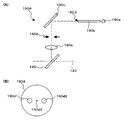
- the alignment optical system 190A is an optical system for projecting an alignment bright spot used for alignment of the optical system with respect to the eye E to the eye E.
- the alignment bright spot includes an alignment (alignment in the xy direction shown in FIG. 1) that aligns the apex position (corneal apex) of the cornea Ec of the eye E with the optical axes of the optical systems 100 and 120, and the eye E and the optical system. Used for both alignment of the distance between 100 and 120 (z direction in FIG. 1; working distance; distance between the cornea Ec (corneal apex) of the eye E and the objective lens 113). (For example, see JP-A-11-4808).
- the alignment optical system 190A includes an alignment light source 190a, a light guide 190b, a reflection mirror 190c, a two-hole aperture 190d, and a relay lens 190e together with the half mirror 190.
- the alignment light source 190a includes, for example, a light source such as an LED that outputs light in the near infrared region (alignment light).
- the two-hole aperture 190d has two holes 190d1 and 190d2 as shown in FIG.
- the holes 190d1 and 190d2 are formed at positions symmetrical with respect to the center position 190d3 of the disc-shaped two-hole aperture 190d, for example.
- the two-hole aperture 190d is disposed such that its center position 190d3 is located on the optical axis of the alignment optical system 190A.
- the alignment light emitted from the exit end 190 ⁇ of the light guide 190b is reflected by the reflection mirror 190c and guided to the two-hole aperture 190d.
- the alignment light (a part) that has passed through the holes 190d1 and 190d2 of the two-hole aperture 190d is reflected by the half mirror 190 and guided to the aperture mirror 112 via the relay lens 190e.
- the relay lens 190e forms an intermediate image of the image of the exit end 190 ⁇ of the light guide 190b at the center position of the hole 112a of the aperture mirror 112 (position on the optical axis of the imaging optical system 120).
- the alignment light that has passed through the hole 112 a of the aperture mirror 112 is projected onto the cornea Ec of the eye E through the objective lens 113.
- the positional relationship between the eye E and the fundus camera unit 1A is appropriate, that is, the distance (working distance) between the eye E and the fundus camera unit 1A is appropriate.
- the optical axis of the optical system of the fundus camera unit 1A and the eye axis of the eye E to be examined are (substantially) coincident with each other, the two light beams (alignment light beams) formed by the two-hole aperture 190d are The image is projected onto the eye E so as to form an image at an intermediate position with respect to the corneal curvature center.
- the corneal reflection light of the two alignment light beams is received by, for example, the image sensor 10a via the photographing optical system 120.
- An image captured by the image sensor 10a is displayed on a display device such as a touch panel monitor 11 or a display (described later) of the arithmetic and control unit 200.
- the display mode of the alignment light at this time is shown in FIG.
- FIG. 3 represents a scale having a parenthesis shape
- symbols P1 and P2 represent received light images (alignment bright spots) of two alignment light beams.
- the scale S is displayed on a display or the like so that the center position thereof coincides with the optical axis of the photographing optical system 120.
- the alignment bright points P1 and P2 are The scale S is displayed at a position shifted in the vertical direction or the horizontal direction. Further, when the working distance is not appropriate, the alignment bright points P1 and P2 are displayed at different positions.
- the alignment bright spots P1 and P2 are as shown in FIG. They are displayed in the scale S in a state where they overlap each other.
- the examiner performs alignment by adjusting the positional relationship between the eye E and the fundus camera unit 1A so that the alignment bright points P1 and P2 overlap each other and are displayed in the scale S. carry out.
- the adjustment of the positional relationship between the eye E and the fundus camera unit 1A is performed by moving the optical system of the fundus camera unit 1A on a movable table, for example, as in the case of a conventional fundus camera.
- the alignment optical system 190A and the optical element of the photographing optical system 120 for guiding the alignment light to the eye E constitute one example of the “alignment means” of the present invention.
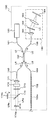
- the configuration of the OCT unit 150 will be described with reference to FIG.
- the OCT unit 150 includes an optical system similar to that of a conventional Fourier domain type optical image measurement device. That is, the OCT unit 150 divides the low-coherence light into reference light and signal light, and causes the signal light passing through the eye to be inspected and the reference light passing through the reference object to generate interference light, and this Detecting means for detecting interference light.
- the detection result (detection signal) of the interference light is sent to the arithmetic and control unit 200.
- the low coherence light source 160 is a broadband light source that outputs a broadband low coherence light L0.
- a broadband light source for example, a super luminescent diode (SLD), a light emitting diode (LED), or the like can be used.
- SLD super luminescent diode
- LED light emitting diode
- the low coherence light L0 includes, for example, light having a wavelength in the near infrared region, and has a temporal coherence length of about several tens of micrometers.
- the low coherence light L0 includes a wavelength longer than the illumination light (wavelength of about 400 nm to 800 nm) of the fundus camera unit 1A, for example, a wavelength in the range of about 800 nm to 900 nm.
- the low coherence light L0 output from the low coherence light source 160 is guided to the optical coupler 162 through the optical fiber 161.
- the optical fiber 161 is configured by, for example, a single mode fiber, a PM fiber (Polarization maintaining fiber), or the like.
- the optical coupler 162 splits the low coherence light L0 into the reference light LR and the signal light LS.
- the optical coupler 162 has both the functions of a means for splitting light (splitter) and a means for superposing light (coupler), but here it is conventionally referred to as an “optical coupler”.
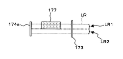
- the reference light LR generated by the optical coupler 162 is guided by an optical fiber 163 made of a single mode fiber or the like and emitted from the end face of the fiber. Further, the reference light LR is converted into a parallel light beam by the collimator lens 171 and passes through the glass block 172 and the density filter 173.
- the optical image measurement device 1 is provided with a plurality (two) of reference mirrors 174a and 174b.
- Each reference mirror 174a, 174b is moved in the traveling direction of the first and second reference beams LRa, LRb (in the direction of the double-headed arrow shown in FIG. 4) by a drive mechanism (see FIG. 5) described later. Thereby, the optical path lengths of the first and second reference beams LRa and LRb can be ensured according to the axial length of the eye E, the working distance, and the like. Further, by moving the reference mirrors 174a and 174b, various depth positions of the eye E can be measured.
- the optical path through the reference mirror 174a is referred to as a first optical path
- the optical path through the reference mirror 174b is referred to as a second optical path.
- the reference mirrors 174a and 174b are arranged so that the optical path length of the first optical path is different from the optical path length of the second optical path. That is, the reference mirrors 174a and 174b are arranged such that the distances to the beam splitter 175 are different from each other.
- the optical path length difference between the first optical path and the second optical path is arranged to be substantially equal to the distance between the cornea and the retina (intercorneal-retinal distance).
- the intercorneal retina distance includes, for example, the value of the axial length obtained from the Gullstrand model eye, the value obtained by statistically processing the examination results of a large number of test eyes (average value, etc.) It is possible to use a standard value for the distance to the retina.
- the intercorneal retina distance does not have to be a distance along the depth direction (z direction), and may be a distance along a direction inclined with respect to the depth direction (for example, in the traveling direction of the signal light LS). May be a distance along.)
- the reference light LR transmitted through the density filter 173 is split by the beam splitter 175 into the first reference light LRa and the second reference light LRb.
- the beam splitter 175 is constituted by a half mirror, for example.
- the first reference light LRa generated by the beam splitter 175 is reflected by the (first) reference mirror 174a and returns to the beam splitter 175.
- the second reference light LRb generated by the beam splitter 175 is reflected by the (second) reference mirror 174 b and returns to the beam splitter 175.
- the beam splitter 175 combines the reference beams LRa and LRb that have returned.
- the combined light of the reference light LRa and LRb generated by the beam splitter 175 (also referred to as reference light LR) passes through the density filter 173 and the glass block 172 again, and is collimated by the collimator lens 171 to the fiber of the optical fiber 163.
- the light is condensed on the end face and guided to the optical coupler 162 through the optical fiber 163.
- the glass block 172 and the density filter 173 act as delay means for matching the optical path lengths (optical distances) of the reference light LR and the signal light LS. Further, the glass block 172 and the density filter 173 function as dispersion compensation means for matching the dispersion characteristics of the reference light LR and the signal light LS.
- the density filter 173 functions as a neutral density filter that reduces the amount of the reference light LR.
- the density filter 173 is configured by, for example, a rotary ND (Neutral Density) filter.
- the density filter 173 is rotationally driven by a drive mechanism (not shown) to change the amount of the reference light LR that contributes to the generation of the interference light LC.
- the signal light LS generated by the optical coupler 162 is guided to the end of the connection line 152 by an optical fiber 164 made of a single mode fiber or the like.
- the optical fiber 164 and the optical fiber 152a may be formed from a single optical fiber, or may be formed integrally by joining the respective end faces.
- the signal light LS is guided by the optical fiber 152a and guided to the fundus camera unit 1A. Further, the signal light LS includes a lens 142, a scanning unit 141, a dichroic mirror 134, a photographing lens 126, a relay lens 125, a half mirror 190, a variable power lens 124, a photographing aperture 121, a hole 112a of a perforated mirror 112, an objective lens.
- the eye E is irradiated through 113.
- the barrier filters 122 and 123 are retracted from the optical path in advance.
- the half mirror 190 may also be retracted from the optical path.
- the signal light LS incident on the eye E is reflected at various parts of the eye E.
- the signal light LS is reflected on the cornea Ec, the crystalline lens, the fundus oculi Ef, and the like.
- the signal light LS is not only reflected by the front surface of the cornea Ec and the fundus oculi Ef, but also scattered at the deep refractive index boundary.
- the signal light LS is reflected not only on the front surface of the cornea Ec but also on the rear surface of the cornea Ec, the boundary of the corneal cell layer, and the like.
- the signal light LS is reflected not only on the front surface (retinal surface) of the fundus oculi Ef but also on the boundary between the cell layers constituting the retina and the boundary between the retina and the choroid. Further, the signal light LS is reflected not only on the front surface but also on the rear surface of the crystalline lens. Therefore, the signal light LS passing through the eye E has information that reflects the front and back forms of various parts of the eye E and information that reflects the state of backscattering at the refractive index boundary of the deep tissue. Contains.
- the signal light LS that has passed through the eye E is guided in the reverse direction along the same path as the signal light LS toward the eye E and is collected on the end face of the optical fiber 152a. Further, the signal light LS enters the OCT unit 150 through the optical fiber 152 a and returns to the optical coupler 162 through the optical fiber 164.
- the optical coupler 162 causes the signal light LS returned via the eye E to interfere with the reference light LR returned after being reflected by the reference mirrors 174a and 174b to generate the interference light LC.
- the interference light LC is guided to the spectrometer 180 through an optical fiber 165 made of a single mode fiber or the like.
- a spectrometer (spectrometer) 180 detects a spectral component of the interference light LC.
- the spectrometer 180 includes a collimator lens 181, a diffraction grating 182, an imaging lens 183, and a CCD 184.
- the diffraction grating 182 may be transmissive or reflective. Further, in place of the CCD 184, other light detection elements (line sensor or area sensor) such as a CMOS may be used.
- the interference light LC incident on the spectrometer 180 is converted into a parallel light beam by the collimator lens 181 and split (spectral decomposition) by the diffraction grating 182.
- the split interference light LC is imaged on the imaging surface of the CCD 184 by the imaging lens 183.
- the CCD 184 detects each spectral component of the separated interference light LC and converts it into electric charges.
- the CCD 184 accumulates this electric charge and generates a detection signal. Further, the CCD 184 sends this detection signal to the arithmetic and control unit 200.
- the spectrometer 180 (in particular, the CCD 184) is an example of the “detection means” of the present invention.
- a Michelson interferometer is used.
- any type of interferometer such as a Mach-Zehnder type can be appropriately used.
- the configuration of the arithmetic and control unit 200 will be described.
- the arithmetic and control unit 200 analyzes the detection signal input from the CCD 184 and forms an OCT image of the eye E to be examined.
- OCT image formation target sites include the fundus oculi Ef, the cornea Ec, and the crystalline lens.
- Arithmetic processing for forming an OCT image is the same as that of a conventional Fourier domain type optical image measurement apparatus.
- the arithmetic and control unit 200 controls each part of the fundus camera unit 1A and the OCT unit 150.
- the arithmetic control device 200 controls the output of illumination light by the observation light source 101 and the imaging light source 103, and controls the insertion / retraction operation of the exciter filters 105 and 106 and the barrier filters 122 and 123 on the optical path. , Operation control of a display device such as LCD 140, control of turning on / off alignment light source 190a, movement control of illumination diaphragm 110 (control of diaphragm value), control of aperture value of photographing diaphragm 121, movement control of zoom lens 124 ( Magnification control). Further, the arithmetic and control unit 200 controls the scanning unit 141 to scan the signal light LS.
- the arithmetic and control unit 200 controls the output of the low coherence light L0 by the low coherence light source 160, the movement control of the reference mirrors 174a and 174b, the rotation operation of the density filter 173 (the light amount of the reference light LR). Control of the amount of decrease in charge), charge accumulation time by CCD 184, charge accumulation timing, signal transmission timing, and the like.
- the arithmetic and control unit 200 includes a microprocessor, a RAM, a ROM, a hard disk drive, a keyboard, a mouse, a display, a communication interface, and the like, like a conventional computer.
- the hard disk drive stores a computer program for controlling the optical image measurement device 1.
- the arithmetic and control unit 200 may include a dedicated circuit board that forms an OCT image based on a detection signal from the CCD 184.
- the optical image measurement device 1 is provided with reference mirror drive mechanisms 176a and 176b.
- the reference mirror drive mechanism 176a moves the reference mirror 174a along the traveling direction of the reference light LRa.
- the reference mirror drive mechanism 176b moves the reference mirror 174b along the traveling direction of the reference light LRb.
- Each reference mirror drive mechanism 176a, 176b includes an actuator and a transmission mechanism.
- the actuator is constituted by, for example, a pulse motor, receives a pulse signal from the arithmetic and control unit 200 (main control unit 211), and generates a driving force corresponding to the number of pulses.
- the transmission mechanism is configured to include, for example, a gear or the like, and transmits the driving force generated by the actuator to the reference mirrors 174a and 174b.
- each reference mirror 174a, 174b operates under the control of the arithmetic and control unit 200.
- the control system of the optical image measurement device 1 is configured around the control unit 210 of the arithmetic and control device 200.
- the control unit 210 includes, for example, the aforementioned microprocessor, RAM, ROM, hard disk drive, communication interface, and the like.
- the control unit 210 is provided with a main control unit 211 and a storage unit 212.
- the main control unit 211 performs the various controls described above. Further, the main control unit 211 performs processing for writing data into the storage unit 212 and processing for reading data from the storage unit 212.
- the main controller 211 controls the reference mirror driving mechanisms 176a and 176b to move the reference mirrors 174a and 174b.
- the main control unit 211 may control the reference mirror driving mechanisms 176a and 176b independently of each other, or may control both of them in conjunction with each other. This interlock control can be applied, for example, when the optical path length difference between the reference beams LRa and LRb is always made equal. When only the interlock control is performed, both reference mirrors 174a and 174b can be moved by a single reference mirror driving mechanism.
- the storage unit 212 stores various data. Examples of data stored in the storage unit 212 include image data of an OCT image, image data of a fundus oculi image Ef ′, and eye information to be examined.
- the eye information includes information about the subject such as patient ID and name, and information about the eye such as left / right eye identification information.
- the eyeball optical information 212a is stored in the storage unit 212 in advance.
- the eyeball optical information 212a includes information related to the eyeball optical system.
- the eyeball optical information 212a includes optical information of the eyeball optical system.
- the eyeball optical system includes a cornea, a crystalline lens, a vitreous body, and the like.
- the eyeball optical information 212a includes, as information on the cornea, the curvature radii of the front surface (front surface) and the back surface of the cornea, the thickness of the cornea, the refractive index of the cornea, and the like.
- the eyeball optical information 212a includes information on the crystalline lens, such as the respective curvature radii of the front and rear surfaces of the crystalline lens, the thickness of the crystalline lens, and the refractive index of the crystalline lens.
- the eyeball optical information 212a also includes information related to the crystalline lens such as the refractive index of the vitreous body.
- the eyeball optical information 212a also includes information regarding the structure of the eyeball optical system.
- Information regarding the structure of the eyeball optical system includes information regarding distances such as the axial length and anterior segment distance.
- the anterior segment distance represents the distance between the front surface of the cornea and the rear surface of the crystalline lens.
- Information on the structure of the eyeball optical system includes position information on the components of the eyeball optical system, position information on optical feature points (main points, focal points, etc.), and refractive power information on the eyeball optical system. It may be.
- Various values included in the eyeball optical information 212a may be standard values (standard values) or values (measured values) obtained by actually inspecting the eye to be examined.
- the standard value for example, a value of a Gull strand model eye can be used.
- a statistically calculated value based on a plurality of eye examination results can be used as a standard value.
- the measurement value the examination result of each eye to be examined can be used individually. In this case, each examination result is stored and managed in association with the identification information of the eye to be examined (subject).
- the image forming unit 220 receives image signals from the imaging devices 10 and 12 and forms image data of the fundus oculi image Ef ′.
- the image forming unit 220 forms tomographic image data of the fundus oculi Ef based on the detection signal from the CCD 184.
- This process includes processes such as noise removal (noise reduction), filter processing, FFT (Fast Fourier Transform), and the like, as in the conventional Fourier domain type OCT technology.
- the image forming unit 220 includes, for example, the above-described microprocessor, circuit board, communication interface, and the like.
- image data and “image” presented based on the “image data” may be identified with each other.
- the image forming unit 220 is provided with an interference component extracting unit 221.
- the interference component extraction unit 221 operates when simultaneously measuring a plurality of parts of the eye E with different depth positions (positions in the z direction).
- the optical image measurement device 1 includes two reference mirrors 174a and 174b. These reference mirrors 174a and 174b are arranged so as to form a predetermined optical path length difference as described above. Therefore, the interference light LC includes information (interference components) representing the respective forms of the two parts of the eye E that are separated in the depth direction by a distance corresponding to the optical path length difference. Therefore, the detection signal output from the CCD 184 includes signal components corresponding to each of these two parts.
- the detection signal output from the CCD 184 includes the fundus oculi.
- a signal component corresponding to Ef (retina) and a signal component corresponding to cornea Ec are included.
- the reference mirror 174a is disposed at a position corresponding to the fundus oculi Ef” means that the optical distance from the optical coupler 162 to the reference mirror 174a and the distance from the optical coupler 162 to the fundus oculi Ef are (substantially). Means equal. The same applies to the reference mirror 174b and the cornea Ec. Since the optical image measurement device 1 generates the interference light LC using the low coherence light L0, the optical image measurement device 1 functions to selectively form an image of the part of the eye E corresponding to each reference mirror 174a, 174b. is there.
- the interference component extraction unit 221 extracts two signal components from the detection signal output from the CCD 184. An example of this processing will be described.
- the detection signal includes a signal component (fundus component) corresponding to the fundus oculi Ef and a signal component (corneal component) corresponding to the cornea Ec.
- the fundus component and the corneal component have different frequency components (frequency bands) in the detection signal. That is, the detection signal is a signal obtained by superimposing the frequency component constituting the fundus component and the frequency component constituting the corneal component (in addition, noise is also included).
- the interference component extraction unit 221 extracts various frequency components included in the detection signal (after removing noise as necessary). This process is performed, for example, by an arbitrary frequency resolution process. Further, the interference component extraction unit 221 selects a fundus component and a corneal component from the extracted frequency components. This process can be executed, for example, by selecting a frequency component determined by measurement in advance. In addition, considering that frequency components other than the fundus component and the corneal component are noise components, a frequency component having a strong signal strength may be selected from the extracted frequency components.
- the image forming unit 220 forms a tomographic image of the fundus oculi Ef based on the fundus component, and forms a tomographic image of the cornea Ec based on the corneal component.
- the image processing unit 230 performs various types of image processing and analysis processing on the image formed by the image forming unit 220. For example, the image processing unit 230 executes various correction processes such as image brightness correction and dispersion correction.
- the image processing unit 230 forms image data of a three-dimensional image of the fundus oculi Ef by executing an interpolation process for interpolating pixels between tomographic images formed by the image forming unit 220.
- the image data of a three-dimensional image means image data in which pixel positions are defined by a three-dimensional coordinate system.
- image data of a three-dimensional image there is image data composed of voxels arranged three-dimensionally. This image data is called volume data or voxel data.
- the image processing unit 230 When displaying an image based on volume data, the image processing unit 230 performs a rendering process (such as volume rendering or MIP (Maximum Intensity Projection)) on the volume data, and views the image from a specific line-of-sight direction.
- Image data of a pseudo three-dimensional image is formed. This pseudo three-dimensional image is displayed on a display device such as the display unit 240.
- stack data of a plurality of tomographic images is image data of a three-dimensional image.
- the stack data is image data obtained by three-dimensionally arranging a plurality of tomographic images obtained along a plurality of scanning lines based on the positional relationship of the scanning lines. That is, stack data is image data obtained by expressing a plurality of tomographic images originally defined by individual two-dimensional coordinate systems by one three-dimensional coordinate system (that is, by embedding them in one three-dimensional space). is there.
- the image processing unit 230 includes, for example, the above-described microprocessor, RAM, ROM, hard disk drive, circuit board, and the like.
- the image processing unit 230 is provided with an analysis processing unit 231.
- the analysis processing unit 231 obtains a predetermined physical quantity of the eye E by analyzing a plurality of tomographic images acquired by simultaneous measurement of a plurality of parts of the eye E.
- the analysis processing unit 231 specifies the scanning mode of the signal light LS based on the obtained physical quantity of the eye E to be examined.
- the physical quantity generally expresses the properties of the physical system and means a quantity in which the measurement method and size unit are specified.
- Examples of physical quantities include mass, length, volume, pressure, time and energy.
- the physical quantity means a quantity that is unique to the object (the eye E to be examined) and that can be objectively measured, and that can be calculated using the quantity.
- the intraocular distance, magnification, corneal curvature radius (corneal curvature), retinal thickness, etc. of the eye E will be described in detail as the predetermined physical quantity.
- the analysis processing unit 231 includes an intraocular distance calculation unit 232, a magnification calculation unit 233, a scanning mode identification unit 234, and a corneal curvature calculation unit 235.
- an intraocular distance calculation unit 232 calculates the corneal curvature radius included in the eyeball optical information 212a and uses the actual measured value of the corneal curvature radius of the eye E. Absent.
- the intraocular distance calculation unit 232 obtains a distance between a position in one tomographic image and a position in another tomographic image among a plurality of tomographic images of the eye E to be examined.
- the intraocular distance calculation unit 232 analyzes the tomographic image (fundus tomographic image) of the fundus oculi Ef and the tomographic image (corneal tomographic image) of the cornea Ec, and calculates the intercorneal retina distance of the eye E to be examined.
- tomographic image fundus tomographic image
- the tomographic image corneal tomographic image
- the intraocular distance calculation unit 232 can obtain an arbitrary intraocular distance of the eye E in addition to the corneal interretinal distance.
- the intraocular distance includes the distance between two points inside the eye E, the distance between one point on the surface of the eye E and one point inside, and the two points on the surface of the eye E. The distance shall be included.
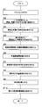
- the intraocular distance calculation unit 232 first acquires the optical path length difference between the reference light LRa and the reference light LRb when simultaneous measurement for acquiring a fundus tomographic image and a corneal tomographic image is executed.
- This optical path length difference can be acquired from the positions of the two reference mirrors 174a and 174b, for example.
- the optical path length difference of the reference mirrors 174a and 174b can be set to be approximately equal to the standard value of the intercorneal retina distance (such as the axial length).
- the optical path length difference acquired by the intraocular distance calculation unit 232 becomes a standard value of the intercorneal retina distance.
- the optical path length difference can be obtained based on the positions of the reference mirrors 174a and 174b at the time of simultaneous measurement.
- the position of each reference mirror 174a, 176b can be acquired based on, for example, the number of pulses of the pulse signal sent from the main control unit 211 to each reference mirror drive mechanism 176a, 176b. Further, the position of each reference mirror 174a, 174b may be detected by a position sensor.
- the intraocular distance calculation unit 232 that acquired the optical path length difference between the reference lights LRa and LRb divides the value of the optical path length difference by the refractive index of the eyeball optical system.
- this refractive index for example, a value (standard value, measured value) recorded in the eyeball optical information 212a can be used.
- the optical distance expressed by the optical path length difference is converted into a spatial distance.
- the intraocular distance calculation unit 232 determines the intercorneal retina distance of the eye E based on the obtained spatial distance, the fundus tomographic image, and the corneal tomographic image. This calculation process will be described below.
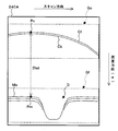
- the above spatial distance is approximately equal to the distance between the fundus tomographic image and the corneal tomographic image. That is, the above spatial distance is defined between a predetermined position in the frame where the fundus tomographic image is drawn (for example, the upper end of the frame) and a predetermined position in the frame where the corneal tomographic image is drawn (the same position as the former). It is almost equal to the distance in the depth direction. Considering this relationship, both tomographic images can be expressed in the same coordinate system (in particular, the z coordinate).
- the intraocular distance calculation unit 232 analyzes the fundus tomographic image to identify an image region (inner boundary membrane region) corresponding to the inner limiting membrane (retinal surface), and analyzes the corneal tomographic image to correspond to the corneal surface.
- An image region (corneal surface region) is specified.
- This processing can be executed by performing threshold processing and filter processing based on the pixel values (luminance values) of the pixels constituting the tomographic image, as in the conventional case.
- a fundus tomographic image or a corneal tomographic image may be displayed, and an operator may manually designate an inner boundary membrane region or a corneal surface region on the displayed image (the same applies to the following processing).
- the intraocular distance calculation unit 232 specifies, for example, one point in the inner boundary membrane region (for example, a feature point such as the center of the optic disc or the macula). This process can be executed by analyzing the shape of the inner boundary membrane region and specifying a feature point (such as the center position of the depression).
- the intraocular distance calculation unit 232 specifies one point in the corneal surface region having the same x coordinate value (and / or y coordinate value) as the above one point in the inner boundary membrane region.
- the locus of the signal light LS irradiated to the one point in the inner boundary membrane region is inclined with respect to the optical axis of the optical system of the fundus camera unit 1A (in such a case by scanning of the signal light LS).
- a single point in the corneal surface region that intersects the locus may be specified.
- the intraocular distance calculation unit 232 refers to the coordinate system expressing both tomographic images, and based on the coordinate value of the one point in the inner boundary membrane region and the coordinate value of the one point in the corneal surface region. Then, the distance between these two points is calculated. As an example, the intraocular distance calculation unit 232 calculates the distance between these two points by calculating the difference between the z coordinate values of these two points. When two points are not arranged on a straight line extending in the z direction, a general arithmetic expression for obtaining a distance in the xyz coordinate system (a square root of a sum of squares of differences between coordinate values of three coordinate axes) is used. The distance between two points can be calculated. Through the above processing, the corneal retina distance is obtained from the two tomographic images of the eye E. The acquired intercorneal retina distance (intraocular distance) is sent to the magnification calculator 233.
- one point in the corneal surface region is specified after one point in the inner boundary membrane region is specified.
- a reverse process can be executed. For example, first, one point corresponding to the corneal apex may be specified from the corneal surface region, and then one point in the inner boundary membrane region corresponding to this one point may be specified.
- the magnification calculation unit 233 obtains the magnification of the eyeball optical system of the eye E based on the intercorneal retina distance obtained by the intraocular distance calculation unit 232.
- the magnification calculator 233 is an example of the “magnification calculator” of the present invention. Hereinafter, an example of processing executed by the magnification calculator 233 will be described.
- the magnification calculation unit 233 for example, based on the optical information of the eyeball optical system included in the eyeball optical information 212a stored in the storage unit 212 and the intercorneal retina distance obtained by the intraocular distance calculation unit 232.
- the magnification of the eyeball optical system of the optometry E can be obtained.
- the eyeball optical information 212a includes, as described above, the respective curvature radii of the front and back surfaces of the cornea, the thickness of the cornea, the refractive index of the cornea, the respective curvature radii of the front and rear surfaces of the lens, the thickness of the lens, and the refraction of the lens.
- Various optical information of the eyeball optical system such as the refractive index, the refractive index of the vitreous body, and the anterior ocular segment distance (distance between the front surface of the cornea and the rear surface of the crystalline lens) is included.
- the magnification calculation unit 233 first subtracts the value of the anterior segment distance from the corneal interretinal distance obtained by the intraocular distance calculation unit 232 to determine the distance between the lens rear surface and the retina surface (rear eye segment distance). calculate.
- the magnification calculator 233 forms an eyeball model based on the calculated posterior eye distance and the eyeball optical information 212a.
- the eyeball optical information 212a includes a standard value (a value such as a Gullstrand model eye)
- at least the posterior eye segment distance is a value reflecting the eye E to be examined. Therefore, the formed eyeball model reflects the eye E to be examined. Needless to say, the greater the number of measurement values included in the eyeball optical information 212a, the higher the degree of reflection of the eye E.
- An eyeball model is a set of a series of physical quantities representing the shape and properties of an eyeball and its constituent parts, such as a model eye.
- the eyeball model may be a simple set (such as a list) of such physical quantities, or may be an image of the eyeball based on these physical quantities.
- the magnification calculator 233 calculates the magnification of the eyeball optical system based on the formed eyeball model.
- the obtained magnification value is used as the magnification of the eyeball optical system of the eye E.
- the processing for obtaining the magnification is, for example, obtaining the length of the projected image of a unit length image projected onto the fundus oculi Ef (retinal surface) by a general ray tracing calculation, Furthermore, the calculation is performed by calculating the ratio between the length of the projected image and the unit length. Ray tracing calculation
- the scanning mode specifying unit 234 specifies the scanning mode of the signal light LS by the scanning unit 141 that irradiates the signal light LS to a predetermined position of the retina of the eye E based on the obtained magnification and the eyeball model. To do.
- the scanning mode specifying unit 234 is an example of the “specifying means” in the present invention.
- the scanning mode identification unit 234 An example of processing executed by the scanning mode identification unit 234 will be described.
- a case where the irradiation position of the signal light LS is scanned along a circular locus having a predetermined radius centered on the center of the optic disc will be described in detail.
- the intraocular distance calculation unit 232 obtains the intercorneal retina distance between one point corresponding to the center of the optic nerve head in the inner boundary membrane region and one point in the corneal tomographic image (described above).
- the scanning mode identification unit 234 obtains the target scanning mode of the signal light LS by performing, for example, a ray tracing calculation.
- this ray tracing calculation for example, based on the eyeball model and the magnification, for each position on the circular locus in the retina of the eyeball model, the signal light LS for the eyeball model is irradiated with the signal light LS at that position.
- the incident locus (incidence angle with respect to the eye axis or the optical axis of the optical system) is obtained.
- this ray tracing calculation is to reversely calculate the incident locus of the signal light LS such that the target position is the predetermined position of the retina of the eyeball model and the target light is irradiated with the signal light LS.
- the scanning mode specifying unit 234 obtains an operating mode of the scanning unit 141 that realizes the specified scanning mode.
- the direction of the galvanometer mirror in the scanning unit 141 is obtained so that the signal light LS propagates along the specified incident locus.
- the relationship between the direction of the galvano mirror and the propagation trajectory of the signal light LS may be stored in advance.
- the direction of the galvanometer mirror in which the signal light LS propagates along the target trajectory may be reversely calculated by the ray tracing calculation similar to the above (performed with the optical system of the fundus camera unit 1A). Good.
- the corneal curvature calculating unit 235 obtains the corneal curvature radius (or corneal curvature) of the eye E.
- the corneal curvature radius and the corneal curvature are the reciprocals of the other, so if one is obtained, the other is also obtained.
- the corneal curvature calculator 235 is an example of the “corneal curvature radius calculator” of the present invention. Hereinafter, an example of processing executed by the corneal curvature calculation unit 235 will be described.
- the optical image measurement device 1 can perform alignment of the optical system with respect to the eye E using the alignment bright points P1 and P2 (see FIGS. 2 and 3).
- the two alignment light beams forming the alignment bright spots P1 and P2 are the corneal apex and the corneal curvature. Each image is formed at an intermediate position from the center.
- the working distance is the distance between the corneal apex and the optical system.
- the corneal curvature calculating unit 235 obtains the corneal curvature radius using such alignment characteristics. For this purpose, a fundus tomographic image and a corneal tomographic image are formed by performing simultaneous measurement in a state where alignment is appropriate, that is, in a state where the two alignment bright spots P1 and P2 overlap.
- the corneal curvature calculating unit 235 obtains the position of an image corresponding to, for example, the corneal surface in the frame of the corneal tomographic image (particularly the position corresponding to the corneal apex). In addition, when the corneal surface region (position corresponding to the corneal apex) is specified by the intraocular distance calculation unit 232, this specifying result can be used. Then, the corneal curvature calculator 235 calculates the corneal curvature radius of the eye E based on the obtained displacement of the image position on the corneal surface from a predetermined position (described later).
- the corneal curvature calculator 235 calculates the corneal curvature radius of the eye E based on the obtained displacement of the reference mirror 174b from a predetermined position (described later).
- the corneal curvature radius of the model eye (the curvature radius of the front surface of the cornea) is 8 mm.
- the optical system of the fundus camera unit 1A is aligned with this model eye.
- the reference mirror 174b is arranged at a position for measuring the cornea of the model eye, and the OCT unit 150 is operated to measure the cornea of the model eye.
- a tomographic image of the cornea of the model eye is formed based on the measurement result.
- an image position (referred to as a reference position) corresponding to the corneal surface in the frame of the tomographic image is obtained.
- This reference position is stored in the storage unit 212 together with the value of the corneal curvature radius of the model eye, for example.
- the preliminary measurement is finished.
- the optical system is aligned with the eye E, the reference mirror 174a is disposed at a position for measuring the fundus oculi Ef, and the cornea The reference mirror 174b is arranged at a position for measuring Ec. Then, the OCT unit 150 is operated to simultaneously measure the fundus oculi Ef and the cornea Ec. Furthermore, a fundus tomographic image and a corneal tomographic image are formed based on the measurement result.
- the corneal curvature calculator 235 obtains the position of the image corresponding to the corneal surface within the frame of the corneal tomographic image. Furthermore, the corneal curvature calculating unit 235 obtains the displacement of the obtained image position of the corneal surface with respect to the reference position obtained in advance measurement. Then, the corneal curvature calculating unit 235 obtains the corneal curvature radius of the eye E by multiplying the displacement value by 2 and adding 8 mm (corneal curvature radius of the model eye) to the product. When the refractive power of the eye E is taken into consideration, the measured value may be used, or may be obtained based on the lens position of the optical system (position of the zoom lens 124, etc.). A process for obtaining the corneal curvature radius based on the position of the reference mirror 174b can be similarly executed.
- the display unit 240 includes a display.
- the operation unit 250 includes an input device such as a keyboard and a mouse and an operation device. Further, the operation unit 250 may include various buttons and keys provided on the housing of the optical image measurement device 1 or on the outside.
- the display unit 240 and the operation unit 250 need not be configured as individual devices.
- a device in which the display unit 240 and the operation unit 250 are integrated, such as a touch panel LCD, can be used.
- the scanning mode of the signal light LS by the optical image measuring device 1 includes, for example, horizontal scanning, vertical scanning, cross scanning, radiation scanning, circular scanning, concentric scanning, and helical scanning. These scanning modes are selectively used as appropriate in consideration of the observation site of the fundus, the analysis target (such as retinal thickness), the time required for scanning, the precision of scanning, and the like.
- the horizontal scan is to scan the signal light LS in the horizontal direction (x direction).
- the horizontal scan also includes an aspect in which the signal light LS is scanned along a plurality of horizontal scanning lines arranged in the vertical direction (y direction). In this aspect, it is possible to arbitrarily set the scanning line interval. By sufficiently narrowing the interval between the scanning lines, the above-described three-dimensional image can be formed (three-dimensional scan). The same applies to the vertical scan.
- the cross scan scans the signal light LS along a cross-shaped trajectory composed of two linear trajectories (straight trajectories) orthogonal to each other.
- the signal light LS is scanned along a radial trajectory composed of a plurality of linear trajectories arranged at a predetermined angle.
- the cross scan is an example of a radiation scan.
- the circle scan scans the signal light LS along a circular locus.
- the signal light LS is scanned along a plurality of circular trajectories arranged concentrically around a predetermined center position.
- a circle scan is considered a special case of a concentric scan.
- the spiral scan scans the signal light LS along a spiral trajectory.
- the scanning unit 141 can scan the signal light LS independently in the x direction and the y direction, respectively, by the configuration as described above. Therefore, the scanning unit 141 can scan the signal light LS along an arbitrary locus on the xy plane. . Thereby, various scanning modes as described above can be realized.
- a tomographic image in the depth direction along the scanning line can be formed.
- the above-described three-dimensional image can be formed.
- FIG. 6 represents an example of the operation of the optical image measurement device 1. It is assumed that the eyeball optical information 212a is already stored in the storage unit 212. Further, it is assumed that the value of the corneal curvature radius of the model eye and the reference position of the image of the corneal surface in the above-described prior measurement are already stored in the storage unit 212.
- the optical system is aligned with the eye E (S1). As shown in FIG. 3, the alignment is performed by projecting alignment bright points P1 and P2 onto the eye E and adjusting the position of the fundus camera unit 1A while observing the state.
- the reference mirror 174a is disposed at a position corresponding to the fundus oculi Ef
- the reference mirror 174b is disposed at a position corresponding to the cornea Ec (S2).
- the reference mirrors 174a and 174b are arranged at positions that give the reference light beams LRa and LRb an optical path length difference equal to the standard value of the corneal retina distance.
- the reference mirror 174a is arranged at a position where an image of a predetermined part (for example, the retinal surface) of the fundus oculi Ef becomes clear
- the reference mirror 174b is a position where an image of the predetermined part (for example, the corneal surface) of the cornea Ec becomes clear. Placed in.
- the movement operation of the reference mirrors 174a and 174b may be performed manually using the operation unit 250, or may be controlled by the main control unit 211 based on a detection signal or a signal obtained by processing the detection signal. .
- the main control unit 211 controls the low-coherence light source 160, the scanning unit 141, the CCD 184, and the like to execute simultaneous measurement of the fundus oculi Ef and the cornea Ec (S3).
- This simultaneous measurement is started in response to a start request using the operation unit 250, for example. Further, simultaneous measurement may be automatically started in response to the completion of the movement operation of the reference mirrors 174a and 174b.
- the eye E is fixed with an internal fixation target as necessary.
- the interference component extraction unit 221 extracts the fundus component and the corneal component from the detection signal (S4).
- the image forming unit 220 forms a tomographic image of the fundus oculi Ef based on this fundus component, and forms a tomographic image of the cornea Ec based on this corneal component (S5).
- the order in which these tomographic images are formed is arbitrary. Further, both image forming processes may be performed in parallel.
- the image forming unit 220 sends the fundus tomographic image and the corneal tomographic image to the control unit 210.
- the main control unit 211 sends the fundus tomographic image and the corneal tomographic image to the image processing unit 230. Further, the main control unit 211 reads out from the storage unit 212 and sends the eyeball optical information 212 a to the image processing unit 230.
- the storage unit 212 reads various information (described above) referred to by the image processing unit 230 from the storage unit 212 and sends the information to the image processing unit 230.
- the main control unit 211 may cause the display unit 240 to display a fundus tomographic image and a corneal tomographic image.
- An example of the display mode at this time is shown in FIG.
- the main control unit 211 displays the fundus tomographic image Gf and the corneal tomographic image Gc on the display screen (partial region) 240A of the display unit 240.
- the fundus tomographic image Gf and the corneal tomographic image Gc are arranged side by side in the depth direction.
- the tomographic images Gf and Gc may be displayed at the same magnification or at different magnifications. Further, the display interval of the tomographic images Gf and Gc may or may not match the actual interval (for example, the standard value of the intercorneal retina distance).
- Simultaneous measurement for acquiring the tomographic images Gf and Gc is performed by fixing the eye E in the fixation direction for acquiring an image of the optic nerve head.
- the fundus tomographic image Gf depicts the vicinity of the optic disc D of the fundus oculi Ef.
- the symbol Ms represents an image area corresponding to the retina surface (inner boundary film) (inner boundary film area).
- the symbol Cf represents an image region corresponding to the corneal surface (corneal front surface) (corneal surface region).
- a symbol Cb represents an image region corresponding to the corneal posterior surface.
- the intraocular distance calculation unit 232 analyzes the fundus tomographic image and the corneal tomographic image to obtain the intercorneal retina distance of the eye E (S6). In the tomographic images Gf and Gc shown in FIG. 7, the intraocular distance calculation unit 232 is between the point Pc (the position of the corneal apex, etc.) on the cornea surface region Cf and the point Pm on the inner boundary membrane region Ms. The distance Dist is calculated.
- the magnification calculation unit 233 obtains the magnification of the eyeball optical system of the eye E based on the intercorneal retina distance obtained in Step 6 and the eyeball optical information 212a (S7). This process is performed using the eyeball model as described above.
- the scanning mode specifying unit 234 sets the scanning mode of the signal light LS to irradiate the signal light LS to a predetermined position of the retina of the eye E based on the magnification obtained in Step 7 and the eyeball model. Specify (S8). This processing is performed using the ray tracing calculation as described above. Further, when the tomographic images Gf and Gc shown in FIG. 7 are acquired, the scanning mode specifying unit 234, for example, outputs the signal light LS along a circular trajectory centered on the center position of the optic disc D and having a predetermined radius. A scanning mode for scanning the irradiation position is specified. The identified scanning mode is sent to the control unit 210.
- the main control unit 211 controls the low coherence light source 160, the scanning unit 141, the CCD 184, and the like to execute the following main measurement (S9).
- a new low-coherence light is output, and a new signal light based on the new low-coherence light is scanned based on the scanning mode specified in Step 8, and a new signal light is transmitted via the first optical path.
- the reference light and the new signal light passing through the retina are caused to interfere with each other to generate new interference light.
- the CCD 184 detects this new interference light and outputs a new detection signal. Further, the image forming unit 220 forms a new tomographic image of the retina (fundus Ef) based on the new detection signal (S10).
- This new tomographic image is, for example, a tomographic image along a circular trajectory centered on the optic disc center of the fundus oculi Ef and having a predetermined radius.
- the tomographic image of the fundus oculi Ef formed in step 10 is stored in the storage unit 212, for example.
- the retinal thickness may be an evaluation target.
- measurement may be performed along three circular trajectories with radii m1, m2, and m3 centered on the center of the optic nerve head.
- the radii m1, m2, and m3 are set to, for example, 1.2 mm, 1.6 mm, and 2.0 mm, respectively.
- the concentric locus is set in step 8, and a new signal light is scanned based on the concentric locus.
- the image forming unit 220 forms a tomographic image along each of these three circular trajectories, and the image processing unit 230 measures the retinal thickness based on each tomographic image.
- the image processing unit 230 determines whether or not the measured retinal thickness is included in the normal range.
- the main control unit 211 causes the display unit 240 to display the determination result.
- Such processing relating to retinal thickness is described in, for example, Japanese Patent Application No. 2007-45831. This is the end of the description of the operation illustrated in FIG.
- the magnification of the eyeball optical system is obtained by regarding the standard value of the corneal curvature radius as the corneal curvature radius of the eye E to be examined.
- the corneal curvature radius of the eye E is obtained and the magnification is calculated.
- the alignment of the optical system with respect to the eye E is performed (S21), the reference mirrors 174a and 174b are moved (S22), and simultaneous measurement of the fundus oculi Ef and the cornea Ec is executed (S23). ).
- the interference component extraction unit 221 extracts a fundus component and a corneal component from the detection signal (S24).
- the image forming unit 220 forms a fundus tomographic image and a corneal tomographic image based on the extracted two signal components (S25).
- the intraocular distance calculation unit 232 analyzes the fundus tomographic image and the corneal tomographic image to determine the intercorneal retina distance of the eye E (S26).
- the corneal curvature calculator 235 obtains the corneal curvature radius of the eye E based on the corneal tomographic image (S27). As described above, the corneal curvature radius may be obtained based on the position of the reference mirror 174b at the time of simultaneous measurement, that is, the optical path length of the second reference light LRb, instead of the corneal tomographic image.
- step 26 The order of executing the process of step 26 and the process of step 27 is arbitrary. It is also possible to execute these processes in parallel.
- the magnification calculator 233 obtains the magnification of the eyeball optical system of the eye E based on the corneal interretinal distance obtained in step 26, the corneal curvature radius obtained in step 27, and the eyeball optical information 212a ( S28).
- the scanning mode specifying unit 234 specifies the scanning mode of the signal light LS that irradiates the signal light LS to a predetermined position of the retina of the eye E based on the magnification obtained in step 28 and the eyeball model (S29). ).
- the main control unit 211 performs the main measurement while scanning the signal light based on the scanning mode specified in step 29 (S30).
- the image forming unit 220 forms a new tomographic image of the retina (fundus Ef) based on the detection signal obtained in the main measurement (S31). Above, description of the operation
- the optical image measuring device 1 operates as follows. First, the optical image measurement device 1 divides the low-coherence light L0 into the signal light LS and the reference light LR, and divides the optical path of the reference light LR into two optical paths having different optical path lengths, thereby dividing the reference light LR into two. Divided into reference beams LRa and LRb. Furthermore, the optical image measurement device 1 causes the reference light LRa and LRb that have passed through these two optical paths to interfere with the signal light LS that has passed through the eye E, so that two depth positions (fundus Ef, Interference light LC reflecting the form in each of the corneas Ec) is generated, and this interference light LC is detected to generate a detection signal.
- the optical image measurement device 1 divides the low-coherence light L0 into the signal light LS and the reference light LR, and divides the optical path of the reference light LR into two optical paths having different optical path lengths, thereby dividing the reference light LR into two. Divided into reference beams LR
- the optical image measuring device 1 forms a fundus tomographic image and a corneal tomographic image based on the detection signal, and analyzes the tomographic images to obtain a predetermined physical quantity (corneal retina distance) of the eye E to be examined.
- optical image measuring device 1 that operates in this way, measurement of two parts (fundus Ef, cornea Ec) of the eye E can be performed simultaneously, so that the tomographic images of these two parts are depicted. It is possible to measure the physical quantity of the eye E with high accuracy.
- the optical image measurement device 1 acts to obtain the magnification of the eyeball optical system of the eye E based on the intercorneal retina distance obtained as a predetermined physical quantity of the eye E.
- the standard value of the corneal curvature radius and the measured value of the corneal curvature radius of the eye E are used.
- this process forms an eyeball model based on the corneal inter-retinal distance and the eyeball optical information 212a, and is executed based on this eyeball model.
- the optical image measurement device 1 includes a scanning unit 141 that scans the irradiation position of the signal light LS on the eye E. Further, the optical image measurement device 1 specifies a scanning mode of signal light that irradiates signal light to a predetermined position of the retina based on the eyeball model and the magnification, and scans the signal light according to the scanning mode. Then, it acts to form a new fundus tomographic image.
- the magnification of the eyeball optical system of the eye E is estimated based on the fundus tomographic image and corneal tomographic image acquired previously, and the retina is determined based on the estimated value and the eyeball model. It is possible to acquire a tomographic image at a predetermined position.
- the optical image measurement device 1 can obtain the retinal thickness of the eye E based on this new tomographic image. Thereby, the retinal thickness at a predetermined position of the retina can be measured, and for example, the retinal thickness can be evaluated with high accuracy.
- the predetermined physical quantity is not limited to the intercorneal retina distance.
- the size (area, volume, etc.) of the lesion can be obtained as a predetermined physical quantity.
- a predetermined physical quantity of the eye E is obtained by analyzing a plurality of tomographic images of the eye E.
- a detection signal from the CCD 184 or this detection signal is used. It is also possible to obtain a predetermined physical quantity by analyzing a signal obtained by processing.
- the distance between the cornea and the retina is obtained by specifying each position (each coordinate value) on the retina surface and the front surface of the cornea based on the signals obtained by performing FFT on the fundus component and the cornea component extracted from the detection signal. It is possible. As long as the process of forming the tomographic image from the detection signal does not change, the detection signal and the tomographic image can be identified with each other. Therefore, “determining a predetermined physical quantity of an object to be measured by analyzing a plurality of tomographic images” referred to in the present invention includes the processing described in the modification.
- the optical path of the reference light LR is divided into two and the two parts of the eye E are measured simultaneously.
- the optical path of the reference light LR is divided into two and the two parts of the eye E are measured simultaneously.
- three of the objects to be measured are measured. It is also possible to configure to measure two or more parts simultaneously.
- FIG. 9 shows a configuration example of an optical system that divides the optical path of the reference light LR into three. 9 replaces a part of the configuration shown in FIG. 4, and this part is a configuration after the density filter 173 in the optical path of the reference light LR.
- three reference mirrors 174a, 174b, and 174c are provided.
- the reference mirrors 174a, 174b, 174c are moved along the double-headed arrow direction shown in FIG. 9 by the reference mirror driving mechanism.
- the reference light LR that has passed through the density filter 173 is divided into two by the beam splitter 175a.
- the reflected light (reference light LRb) from the beam splitter 175a is guided to the reference mirror 174b.
- the light transmitted through the beam splitter 175a is divided into two by the beam splitter 175b.
- the light reflected by the beam splitter 175b (reference light LRc) is guided to the reference mirror 174c.
- the light (reference light LRa) that has passed through the beam splitter 175b is guided to the reference mirror 174a.
- the reference lights LRa, LRb, and LRc are reflected by the reference mirrors 174a, 174b, and 174c, respectively. These reference lights LRa, LRb, and LRc are combined by beam splitters 175a and 175b (also referred to as reference light LR).
- the reference light LR is superimposed on the signal light LS by the optical coupler 162 (see FIG. 4) to generate the interference light LC.
- the interference light LC includes information representing the forms of the three portions of the eye E corresponding to the optical path lengths of these three optical paths.
- the spectrometer 180 detects a spectral component of the interference light LC and generates a detection signal.
- the image forming unit 220 extracts three signal components from the detection signal, and forms tomographic images of three portions of the eye E based on each signal component.
- the analysis processing unit 231 obtains a predetermined physical quantity by analyzing three tomographic images (at least two of them) based on such simultaneous measurement. The same applies to the case where the reference light LR is divided into four or more.
- the configuration for dividing the reference light is not limited to that of the above embodiment, that is, a beam splitter.
- the optical member 177 is formed of a light-transmitting material having a refractive index different from the atmosphere (air or the like) inside the OCT unit 150.
- the optical member 177 is made of, for example, a glass block.
- the optical member 177 is arranged at a position that transmits only a part of the optical path of the reference light LR, that is, a partial region of the beam cross section of the reference light LR.
- the part of the reference light LR that passes through the optical member 177 (reference light LR1) has an optical path length that is longer than the part that does not pass through the optical member 177 (reference light LR2) due to the influence of the optical member 177.
- the position of the reference mirror 174 is changed to change the optical path length difference between the optical path of the signal light LS and the optical path of the reference light LR.
- the method of changing the optical path length difference is limited to this. Is not to be done.
- the optical path length difference can be changed by moving the fundus camera unit 1A or the OCT unit 150 with respect to the eye E to change the optical path length of the signal light LS. It is also effective to change the optical path length difference by moving the measured object in the depth direction, particularly when the measured object is not a living body part.
- the computer program in the above embodiment can be stored in any recording medium that can be read by the drive device of the computer.
- this recording medium for example, an optical disk, a magneto-optical disk (CD-ROM / DVD-RAM / DVD-ROM / MO, etc.), a magnetic storage medium (hard disk / floppy (registered trademark) disk / ZIP, etc.), etc. are used. Is possible. It can also be stored in a storage device such as a hard disk drive or memory. Furthermore, this program can be transmitted and received through a network such as the Internet or a LAN.
Abstract
A technique for measuring a physical quantity of an object to be measured with high accuracy from OCT images showing different regions of the object. An optical image measuring device (1) splits a low-coherence light beam (LO) into a signal light beam (LS) and a reference light beam (LR), splits the reference light beam (LR) into two reference light beams (LRa, LRb) by dividing the optical path of the reference light beam (LR) into two optical paths having different optical path lengths, causes interference between the reference light beam (LRa) passing through the corresponding optical path and the signal light beam (LS) passing through an eye (E) and interference between the reference light beam (LRb) passing through the corresponding optical path and the signal light beam (Ls), produces an interference light beam (LC) reflecting the forms in two depth positions (the eye ground (Ef) and the cornea (Ec)) of the eye (E), generates a detection signal by detecting the interference light beam (LC), creates an eye ground tomogram and a cornea tomogram from the detection signal, analyzes the tomograms, and determines the distance between the cornea and the retina of the eye (E).
Description
この発明は、光ビームを用いて被測定物体の表面形態や内部形態を表す画像を形成する光画像計測装置に関する。
The present invention relates to an optical image measurement device that forms an image representing a surface form or an internal form of an object to be measured using a light beam.
近年、レーザ光源等からの光ビームを用いて被測定物体の表面形態や内部形態を表す画像を形成する光画像計測技術が注目を集めている。光画像計測技術は、X線CT装置のような人体に対する侵襲性を持たないことから、医療分野や生物学分野における応用の展開が特に期待されている。
In recent years, an optical image measurement technique that forms an image representing the surface form or internal form of an object to be measured using a light beam from a laser light source or the like has attracted attention. Since the optical image measurement technique does not have invasiveness to the human body unlike the X-ray CT apparatus, the development of application in the medical field and the biological field is particularly expected.
特許文献1には、光画像計測技術を適用した装置が開示されている。この装置は、測定腕が回転式転向鏡(ガルバノミラー)により物体を走査し、参照腕に参照ミラーが設置されており、その出口に計測腕及び参照腕からの光束の干渉光の強度を分光器で分析する干渉器が設けられている。更に、参照腕は、参照光光束位相を不連続な値で段階的に変えるように構成されている。
Patent Document 1 discloses an apparatus to which an optical image measurement technique is applied. In this device, the measuring arm scans an object with a rotary turning mirror (galvanomirror), a reference mirror is installed on the reference arm, and the intensity of the interference light of the light beam from the measuring arm and the reference arm is dispersed at the exit. An interferometer is provided for analysis by the instrument. Further, the reference arm is configured to change the phase of the reference light beam stepwise by a discontinuous value.
特許文献1の装置は、いわゆる「フーリエドメインOCT(Fourier Domain Optical Coherence Tomography)」の手法を用いるものである。すなわち、被測定物体に対して低コヒーレンス光のビームを照射し、その反射光と参照光とを重ね合わせて干渉光を生成し、この干渉光のスペクトル強度分布を取得してフーリエ変換を施すことにより被測定物体の深度方向(z方向)の形態を画像化するものである。
The apparatus of Patent Document 1 uses a so-called “Fourier Domain OCT (Fourier Domain Optical Coherence Tomography)” technique. In other words, a low-coherence beam is irradiated onto the object to be measured, the reflected light and the reference light are superimposed to generate interference light, and the spectral intensity distribution of the interference light is acquired and subjected to Fourier transform. Thus, the form of the object to be measured in the depth direction (z direction) is imaged.
更に、特許文献1に記載の装置は、光ビーム(信号光)を走査するガルバノミラーを備え、それにより被測定物体の所望の測定対象領域の画像を形成するようになっている。この装置においては、z方向に直交する1方向(x方向)にのみ光ビームを走査するように構成されているので、この装置により形成される画像は、光ビームの走査方向(x方向)に沿った深度方向(z方向)の2次元断層画像となる。
Furthermore, the apparatus described in Patent Document 1 includes a galvanometer mirror that scans a light beam (signal light), thereby forming an image of a desired measurement target region of the object to be measured. Since this apparatus is configured to scan the light beam only in one direction (x direction) orthogonal to the z direction, the image formed by this apparatus is in the scanning direction (x direction) of the light beam. It becomes a two-dimensional tomographic image in the depth direction (z direction) along.
特許文献2には、信号光を水平方向及び垂直方向に走査することにより水平方向の2次元断層画像を複数形成し、これら複数の断層画像に基づいて測定範囲の3次元の断層情報を取得して画像化する技術が開示されている。この3次元画像化としては、たとえば、複数の断層画像を垂直方向に並べて表示させる方法や(スタックデータなどと呼ばれる)、複数の断層画像にレンダリング処理を施して3次元画像を形成する方法などが考えられる。
In Patent Document 2, a plurality of horizontal two-dimensional tomographic images are formed by scanning signal light in the horizontal direction and the vertical direction, and three-dimensional tomographic information of a measurement range is acquired based on the plurality of tomographic images. A technique for imaging is disclosed. Examples of the three-dimensional imaging include a method of displaying a plurality of tomographic images side by side in a vertical direction (referred to as stack data), and a method of rendering a plurality of tomographic images to form a three-dimensional image. Conceivable.
特許文献3、4には、他のタイプの光画像計測装置が開示されている。特許文献3には、被測定物体に照射される光の波長を走査し、各波長の光の反射光と参照光とを重ね合わせて得られる干渉光に基づいてスペクトル強度分布を取得し、それに対してフーリエ変換を施すことにより被測定物体の形態を画像化する光画像計測装置が記載されている。このような光画像計測装置は、スウェプトソース(Swept Source)タイプなどと呼ばれる。
Patent Documents 3 and 4 disclose other types of optical image measurement devices. Patent Document 3 scans the wavelength of light applied to an object to be measured, acquires a spectral intensity distribution based on interference light obtained by superimposing reflected light of each wavelength and reference light, On the other hand, there is described an optical image measurement device that images the form of an object to be measured by performing Fourier transform on the object. Such an optical image measurement device is called a swept source type.
また、特許文献4には、所定のビーム径を有する光を被測定物体に照射し、その反射光と参照光とを重ね合わせて得られる干渉光の成分を解析することにより、光の進行方向に直交する断面における被測定物体の画像を形成する光画像計測装置が記載されている。このような光画像計測装置は、フルフィールド(full-field)タイプ、或いはエンフェイス(en-face)タイプなどと呼ばれる。
In Patent Document 4, the traveling direction of light is obtained by irradiating the object to be measured with light having a predetermined beam diameter, and analyzing the component of interference light obtained by superimposing the reflected light and the reference light. Describes an optical image measurement device that forms an image of an object to be measured in a cross section orthogonal to the above. Such an optical image measuring device is called a full-field type or an en-face type.
特許文献5には、OCT技術を眼科分野に適用した構成が開示されている。なお、光画像計測装置が眼科分野に応用される以前には、眼底カメラ等の眼科撮影装置が利用されていた(たとえば特許文献6を参照)。
Patent Document 5 discloses a configuration in which the OCT technique is applied to the ophthalmic field. Prior to the application of the optical image measurement device to the ophthalmology field, an ophthalmologic photographing device such as a fundus camera was used (see, for example, Patent Document 6).
OCT技術を用いた眼底撮影装置は、眼底を前方から撮影するだけの眼底カメラと比較して、眼底の断層画像や3次元画像を取得できるという利点がある。そのため、診断精度の向上や病変の早期発見への寄与が期待されている。
The fundus imaging apparatus using the OCT technique has an advantage that a tomographic image and a three-dimensional image of the fundus can be acquired as compared with a fundus camera that only images the fundus from the front. Therefore, it is expected to contribute to improvement of diagnostic accuracy and early detection of lesions.
光画像計測装置により取得される画像(OCT画像:断層画像、3次元画像等)は、被測定物体(又はその一部)の各種物理量の計測に用いられる。たとえば眼科分野においては、病変部のサイズや隅角などの物理量の計測に利用されている。
An image (OCT image: tomographic image, three-dimensional image, etc.) acquired by an optical image measurement device is used for measuring various physical quantities of an object to be measured (or a part thereof). For example, in the field of ophthalmology, it is used to measure physical quantities such as the size and corners of a lesion.
しかしながら、従来の光画像計測装置では、一枚のOCT画像に描写された対象物の物理量を計測することはできるが、複数のOCT画像に亘って描写された対象物の物理量を高い確度で計測することは困難である。
However, the conventional optical image measurement device can measure the physical quantity of the object depicted in one OCT image, but measures the physical quantity of the object depicted across multiple OCT images with high accuracy. It is difficult to do.
たとえば、従来の光画像計測装置によれば、一枚のOCT画像中の二点間の距離については計測できたが、第1のOCT画像中の一点と第2のOCT画像中の一点との間の距離を高い確度で計測することは難しかった。特に、生体眼のように静止状態にない被測定物体については、第1のOCT画像と第2のOCT画像の取得タイミングにズレが生じるので、計測確度が低下する可能性が高かった。
For example, according to a conventional optical image measurement device, the distance between two points in one OCT image could be measured, but one point in the first OCT image and one point in the second OCT image. It was difficult to measure the distance between them with high accuracy. In particular, for a measured object that is not in a stationary state, such as a living eye, there is a high possibility that the measurement accuracy will be reduced because the acquisition timing of the first OCT image and the second OCT image is shifted.
このように、従来の光画像計測装置では、一枚のOCT画像で描写可能な比較的狭い範囲における物理量の計測は容易であったが、これを超える比較的広い範囲における物理量を高い確度で計測することは困難であった。
As described above, in the conventional optical image measurement device, it was easy to measure a physical quantity in a relatively narrow range that can be drawn with one OCT image, but the physical quantity in a relatively wide range exceeding this can be measured with high accuracy. It was difficult to do.
この発明は、このような問題を解決するためになされたもので、その目的は、被測定物体の異なる部位を描写する複数のOCT画像を基に被測定物体の物理量を高い確度で計測可能な光画像計測装置を提供することにある。
The present invention has been made to solve such a problem, and its object is to measure a physical quantity of a measured object with high accuracy based on a plurality of OCT images depicting different parts of the measured object. The object is to provide an optical image measuring device.
上記目的を達成するために、請求項1に記載の発明は、低コヒーレンス光を信号光と参照光とに分割し、前記参照光の光路を光路長の異なる複数の光路に分割することで前記参照光を複数の参照光に分割し、前記複数の光路をそれぞれ経由した前記複数の参照光と被測定物体を経由した前記信号光とを干渉させて、前記被測定物体の複数の深度位置のそれぞれにおける形態を反映した干渉光を生成する光学系と、前記生成された干渉光を検出して検出信号を生成する検出手段と、前記生成された検出信号に基づいて、前記複数の深度位置における前記被測定物体の形態を表す複数の断層画像をそれぞれ形成する画像形成手段と、前記複数の断層画像を解析して前記被測定物体の所定の物理量を求める解析手段と、を備えることを特徴とする光画像計測装置である。
In order to achieve the above object, the invention described in claim 1 divides low-coherence light into signal light and reference light, and divides the optical path of the reference light into a plurality of optical paths having different optical path lengths. The reference light is divided into a plurality of reference lights, and the plurality of reference lights respectively passing through the plurality of optical paths are caused to interfere with the signal light passing through the object to be measured, so that a plurality of depth positions of the object to be measured are obtained. An optical system that generates interference light reflecting the form in each, detection means that detects the generated interference light and generates a detection signal, and at the plurality of depth positions based on the generated detection signal And image forming means for forming a plurality of tomographic images each representing a form of the object to be measured, and an analyzing means for analyzing the plurality of tomographic images to obtain a predetermined physical quantity of the object to be measured. Do An image measuring apparatus.
また、請求項2に記載の発明は、請求項1に記載の光画像計測装置であって、前記光学系は、前記低コヒーレンス光から分割された参照光を前記複数の参照光に分割するビームスプリッタと、前記複数の参照光のそれぞれの光路に設けられた参照ミラーとを含み、前記ビームスプリッタは、前記参照ミラーによりそれぞれ反射された前記複数の参照光を合成し、前記光学系は、前記合成された前記複数の参照光を前記信号光に干渉させて前記干渉光を生成する、ことを特徴とする。
The invention according to claim 2 is the optical image measurement device according to claim 1, wherein the optical system splits the reference light divided from the low-coherence light into the plurality of reference lights. A splitter and a reference mirror provided in each optical path of the plurality of reference lights, the beam splitter combines the plurality of reference lights respectively reflected by the reference mirror, and the optical system includes the optical system The interference light is generated by causing the plurality of combined reference lights to interfere with the signal light.
また、請求項3に記載の発明は、請求項1に記載の光画像計測装置であって、前記光学系は、前記低コヒーレンス光から分割された参照光の一部分の光路長を延長する光学部材と、前記光学部材により光路長が延長された前記参照光の一部分と、前記参照光の他の部分とを反射する参照ミラーとを含み、前記参照ミラーにより反射された前記参照光を前記信号光に干渉させて前記干渉光を生成する、ことを特徴とする。
The invention according to claim 3 is the optical image measuring device according to claim 1, wherein the optical system extends an optical path length of a part of the reference light divided from the low coherence light. And a reference mirror that reflects a part of the reference light whose optical path length is extended by the optical member and another part of the reference light, and the reference light reflected by the reference mirror is converted into the signal light. And generating the interference light.
また、請求項4に記載の発明は、請求項1に記載の光画像計測装置であって、前記解析手段は、前記所定の物理量として、前記複数の断層画像のうちの一の断層画像中の位置と他の断層画像中の位置との間の距離を求める、ことを特徴とする。
The invention according to claim 4 is the optical image measurement device according to claim 1, wherein the analysis unit includes the predetermined physical quantity in one tomographic image of the plurality of tomographic images. A distance between the position and a position in another tomographic image is obtained.
また、請求項5に記載の発明は、請求項4に記載の光画像計測装置であって、前記被測定物体は生体眼であり、前記複数の参照光は、前記生体眼の網膜に対応する光路長を有する第1の光路を経由する第1の参照光と、前記生体眼の角膜に対応する光路長を有する第2の光路を経由する第2の参照光とを含み、前記画像形成手段は、前記第1の参照光と前記網膜で反射された前記信号光との干渉成分に相当する第1の信号成分を前記検出信号から抽出して前記網膜の形態を表す第1の断層画像を前記一の断層画像として形成し、かつ、前記第2の参照光と前記角膜で反射された前記信号光との干渉成分に相当する第2の信号成分を前記検出信号から抽出して前記角膜の形態を表す第2の断層画像を前記他の断層画像として形成し、前記解析手段は、前記第1及び前記第2の断層画像を解析して、前記生体眼の角膜網膜間距離を求める、ことを特徴とする。
The invention according to claim 5 is the optical image measurement device according to claim 4, wherein the object to be measured is a living eye, and the plurality of reference lights correspond to a retina of the living eye. A first reference light passing through a first optical path having an optical path length; and a second reference light passing through a second optical path having an optical path length corresponding to the cornea of the living eye. Extracts a first signal component corresponding to an interference component between the first reference light and the signal light reflected by the retina from the detection signal, and obtains a first tomographic image representing the form of the retina. A second signal component formed as the one tomographic image and corresponding to an interference component between the second reference light and the signal light reflected by the cornea is extracted from the detection signal, and Forming a second tomographic image representing a form as the other tomographic image, and performing the analysis Stage, by analyzing the first and said second tomographic image, obtains the corneal retinal distance between the living eye, characterized in that.
また、請求項6に記載の発明は、請求項5に記載の光画像計測装置であって、前記第1の光路と前記第2の光路とは、角膜網膜間距離の標準値に略等しい光路長差を有し、前記解析手段は、予め記憶された眼球光学情報に含まれる眼球光学系の屈折率の値で前記標準値を除算し、その商の値と前記第1及び前記第2の断層画像とに基づいて前記角膜網膜間距離を求める、ことを特徴とする。
The invention according to claim 6 is the optical image measurement device according to claim 5, wherein the first optical path and the second optical path are substantially equal to a standard value of a corneal-retinal distance. The analyzing means divides the standard value by the refractive index value of the eyeball optical system included in the eyeball optical information stored in advance, and calculates the quotient value and the first and second values. The intercorneal retina distance is obtained based on a tomographic image.
また、請求項7に記載の発明は、請求項5に記載の光画像計測装置であって、前記解析手段は、前記所定の物理量として、前記求められた角膜網膜間距離に基づいて前記生体眼の眼球光学系の倍率を求める倍率演算手段を含む、ことを特徴とする。
The invention according to claim 7 is the optical image measurement device according to claim 5, wherein the analysis unit uses the living eye as the predetermined physical quantity based on the calculated intercorneal retinal distance. Magnification calculating means for determining the magnification of the eyeball optical system is included.
また、請求項8に記載の発明は、請求項7に記載の光画像計測装置であって、前記倍率演算手段は、予め記憶された眼球光学情報に含まれる眼球光学系の光学情報と、前記求められた角膜網膜間距離とに基づいて前記倍率を求める、ことを特徴とする。
The invention according to claim 8 is the optical image measurement device according to claim 7, wherein the magnification calculation means includes optical information of an eyeball optical system included in eyeball optical information stored in advance, and The magnification is obtained based on the obtained intercorneal retina distance.
また、請求項9に記載の発明は、請求項8に記載の光画像計測装置であって、前記眼球光学情報は、角膜の前後面のそれぞれの曲率半径、角膜の厚さ、角膜の屈折率、水晶体の前後面のそれぞれの曲率半径、水晶体の厚さ、水晶体の屈折率、硝子体の屈折率、及び、角膜前面と水晶体後面との間の距離を表す前眼部距離のそれぞれの値を含み、前記倍率演算手段は、前記角膜網膜間距離から前記前眼部距離の値を減算して水晶体後面と網膜表面との間の距離を表す後眼部距離を算出し、前記眼球光学情報及び前記後眼部距離とに基づいて眼球モデルを形成し、前記眼球モデルに基づいて前記倍率を求める、ことを特徴とする。
The invention according to claim 9 is the optical image measurement device according to claim 8, wherein the eyeball optical information includes the respective radii of curvature of the front and back surfaces of the cornea, the thickness of the cornea, and the refractive index of the cornea. The respective curvature radii of the front and back surfaces of the lens, the thickness of the lens, the refractive index of the lens, the refractive index of the vitreous, and the anterior segment distance representing the distance between the anterior cornea and the posterior surface of the lens. The magnification calculation means subtracts the value of the anterior segment distance from the corneal interretinal distance to calculate a posterior segment distance representing a distance between the posterior surface of the lens and the retinal surface; An eyeball model is formed based on the posterior eye distance, and the magnification is obtained based on the eyeball model.
また、請求項10に記載の発明は、請求項9に記載の光画像計測装置であって、前記生体眼に対して前記光学系を位置合わせするアライメント手段を更に備え、前記解析手段は、前記位置合わせが行われた後に前記光学系により生成された干渉光に基づく前記第2の断層画像のフレーム内における位置を特定し、該特定された位置に基づいて前記生体眼の角膜曲率半径を求める角膜曲率半径演算手段を含み、前記倍率演算手段は、前記眼球光学情報に含まれる角膜の曲率半径の値の代わりに、前記求められた角膜曲率半径に基づいて前記眼球モデルを形成する、ことを特徴とする。
The invention according to claim 10 is the optical image measurement device according to claim 9, further comprising alignment means for aligning the optical system with respect to the living eye, wherein the analysis means includes A position in the frame of the second tomographic image based on the interference light generated by the optical system after alignment is specified, and a corneal curvature radius of the living eye is obtained based on the specified position Corneal curvature radius calculating means, and the magnification calculating means forms the eyeball model based on the calculated corneal curvature radius instead of the value of the curvature radius of the cornea included in the eyeball optical information. Features.
また、請求項11に記載の発明は、請求項9に記載の光画像計測装置であって、前記生体眼に対して前記光学系を位置合わせするアライメント手段を更に備え、前記解析手段は、前記位置合わせが行われた後に前記光学系により干渉光が生成されたときの前記第2の光路の光路長に基づいて前記生体眼の角膜曲率半径を求める角膜曲率半径演算手段を含み、前記倍率演算手段は、前記眼球光学情報に含まれる角膜の曲率半径の値の代わりに、前記求められた角膜曲率半径に基づいて前記眼球モデルを形成する、ことを特徴とする。
The invention according to claim 11 is the optical image measurement device according to claim 9, further comprising alignment means for aligning the optical system with respect to the living eye, wherein the analysis means comprises Corneal curvature radius calculating means for determining a corneal curvature radius of the living eye based on an optical path length of the second optical path when interference light is generated by the optical system after alignment is performed, and the magnification calculation The means forms the eyeball model based on the calculated corneal curvature radius instead of the value of the corneal curvature radius included in the eyeball optical information.
また、請求項12に記載の発明は、請求項9に記載の光画像計測装置であって、前記光学系は、前記生体眼に対する前記信号光の照射位置を走査する走査手段を含み、前記解析手段は、前記眼球モデル及び前記求められた倍率に基づいて、前記網膜の所定位置に前記信号光を照射させるような前記走査手段による前記信号光の走査態様を特定する特定手段を含み、前記光学系は、新たな低コヒーレンス光を信号光と参照光とに分割し、前記特定された走査態様に基づき前記走査手段により当該新たな信号光を走査しつつ、前記第1の光路を経由した当該新たな参照光と前記網膜を経由した当該新たな信号光とを干渉させて新たな干渉光を生成し、前記検出手段は、前記新たな干渉光を検出して新たな検出信号を生成し、前記画像形成手段は、前記新たな検出信号に基づいて、前記網膜の新たな断層画像を形成する、ことを特徴とする。
The invention according to claim 12 is the optical image measurement device according to claim 9, wherein the optical system includes a scanning unit that scans an irradiation position of the signal light with respect to the living eye, and the analysis is performed. The means includes specifying means for specifying a scanning mode of the signal light by the scanning means for irradiating the signal light to a predetermined position of the retina based on the eyeball model and the obtained magnification. The system divides a new low-coherence light into a signal light and a reference light, and scans the new signal light by the scanning unit based on the specified scanning mode, while passing through the first optical path. The new reference light and the new signal light passing through the retina are caused to interfere to generate new interference light, and the detection means detects the new interference light and generates a new detection signal, The image forming means On the basis of the new detection signal, to form a new tomographic image of the retina, characterized in that.
また、請求項13に記載の発明は、請求項12に記載の光画像計測装置であって、前記特定手段は、前記眼球モデル及び前記求められた倍率に基づく光線追跡演算を行うことにより、前記眼球モデルの網膜の前記所定位置に信号光が照射されるような前記走査態様を特定する、ことを特徴とする。
The invention according to claim 13 is the optical image measurement device according to claim 12, wherein the specifying unit performs a ray tracing calculation based on the eyeball model and the obtained magnification. The scanning mode in which signal light is irradiated to the predetermined position of the retina of the eyeball model is characterized.
また、請求項14に記載の発明は、請求項12に記載の光画像計測装置であって、前記特定手段は、前記網膜の視神経乳頭中心を中心とし所定半径を有する円形の軌跡に沿って前記信号光の照射位置を走査させるための前記走査態様を特定する、ことを特徴とする。
The invention according to claim 14 is the optical image measurement device according to claim 12, wherein the specifying means is arranged along a circular locus having a predetermined radius centered on the optic disc center of the retina. The scanning mode for scanning the irradiation position of the signal light is specified.
また、請求項15に記載の発明は、請求項12に記載の光画像計測装置であって、前記解析手段は、前記新たな断層画像に基づいて前記生体眼の網膜厚を求める、ことを特徴とする。
The invention according to claim 15 is the optical image measurement device according to claim 12, wherein the analysis means obtains the retinal thickness of the living eye based on the new tomographic image. And
この発明に係る光画像計測装置は、低コヒーレンス光を信号光と参照光とに分割し、更に、この参照光を複数の参照光に分割する。更に、この発明に係る光画像計測装置は、これら複数の光路をそれぞれ経由した参照光と被測定物体を経由した信号光とを干渉させて、被測定物体の複数の深度位置のそれぞれにおける形態を反映した干渉光を生成し、この干渉光の検出結果に基づいて被測定物体の複数の断層画像を形成する。そして、この発明に係る光画像計測装置は、これら複数の断層画像を解析して被測定物体の所定の物理量を求める。
The optical image measurement device according to the present invention divides low-coherence light into signal light and reference light, and further divides this reference light into a plurality of reference lights. Furthermore, the optical image measurement device according to the present invention causes the reference light passing through the plurality of optical paths and the signal light passing through the measured object to interfere with each other so that the form at each of the plurality of depth positions of the measured object is The reflected interference light is generated, and a plurality of tomographic images of the object to be measured are formed based on the detection result of the interference light. Then, the optical image measurement device according to the present invention obtains a predetermined physical quantity of the object to be measured by analyzing the plurality of tomographic images.
このように作用する光画像計測装置によれば、被測定物体の複数の部位の計測を同時に実行できるので、これら複数の部位の断層画像(OCT画像)に描写された被測定物体の物理量を高い確度で計測することが可能である。
According to the optical image measurement device that operates in this manner, since measurement of a plurality of parts of the object to be measured can be performed simultaneously, the physical quantity of the object to be measured depicted in the tomographic images (OCT images) of these parts is high. It is possible to measure with accuracy.
1 光画像計測装置
1A 眼底カメラユニット
141 走査ユニット
150 OCTユニット
160 低コヒーレンス光源
174a、174b 参照ミラー
176a、176b 参照ミラー駆動機構
180 スペクトロメータ
184 CCD
190A アライメント光学系
200 演算制御装置
210 制御部
211 主制御部
212 記憶部
212a 眼球光学情報
220 画像形成部
221 干渉成分抽出部
230 画像処理部
231 解析処理部
232 眼内距離演算部
233 倍率演算部
234 走査態様特定部
235 角膜曲率演算部
240 表示部
250 操作部 1 Optical Image Measuring Device 1AFundus Camera Unit 141 Scanning Unit 150 OCT Unit 160 Low Coherence Light Source 174a, 174b Reference Mirror 176a, 176b Reference Mirror Drive Mechanism 180 Spectrometer 184 CCD
190AAlignment Optical System 200 Arithmetic Control Unit 210 Control Unit 211 Main Control Unit 212 Storage Unit 212a Eyeball Optical Information 220 Image Forming Unit 221 Interference Component Extraction Unit 230 Image Processing Unit 231 Analysis Processing Unit 232 Intraocular Distance Calculation Unit 233 Magnification Calculation Unit 234 Scanning mode identification unit 235 Corneal curvature calculation unit 240 Display unit 250 Operation unit
1A 眼底カメラユニット
141 走査ユニット
150 OCTユニット
160 低コヒーレンス光源
174a、174b 参照ミラー
176a、176b 参照ミラー駆動機構
180 スペクトロメータ
184 CCD
190A アライメント光学系
200 演算制御装置
210 制御部
211 主制御部
212 記憶部
212a 眼球光学情報
220 画像形成部
221 干渉成分抽出部
230 画像処理部
231 解析処理部
232 眼内距離演算部
233 倍率演算部
234 走査態様特定部
235 角膜曲率演算部
240 表示部
250 操作部 1 Optical Image Measuring Device 1A
190A
この発明に係る光画像計測装置の実施形態の一例について、図面を参照しながら詳細に説明する。この実施形態では、眼科分野において使用され、生体眼のOCT画像を取得する装置について説明する。生体眼は、固視微動等の眼球運動や心臓の拍動などにより常時動いている。なお、生体眼以外の被測定物体(特に動きを伴うもの)のOCT画像を取得する場合についても、同様の構成により同様の効果を得ることが可能である。
An example of an embodiment of an optical image measurement device according to the present invention will be described in detail with reference to the drawings. In this embodiment, an apparatus that is used in the ophthalmic field and acquires an OCT image of a living eye will be described. The living eye always moves due to eye movement such as fixation fine movement or heart beat. Note that the same effect can be obtained with the same configuration when acquiring an OCT image of an object to be measured other than a living eye (particularly, with movement).
この実施形態では、フーリエドメインタイプの手法を適用する構成について詳しく説明する。特に、この実施形態では、特許文献5に開示された装置とほぼ同様の構成を具備する光画像計測装置を取り上げる。なお、他の構成を適用する場合においても、この実施形態と同様の構成を適用することで同様の作用及び効果が得られる。たとえば、スウェプトソースタイプのように信号光を走査(スキャン)して計測を行う任意のタイプのOCT技術に対して、この実施形態に係る構成を適用することが可能である。また、フルフィールドタイプのように信号光をスキャンしないタイプのOCT技術に対して、この実施形態に係る構成を適用することも可能である。
In this embodiment, a configuration to which a Fourier domain type technique is applied will be described in detail. In particular, in this embodiment, an optical image measurement device having substantially the same configuration as the device disclosed in Patent Document 5 is taken up. Even when other configurations are applied, the same operations and effects can be obtained by applying the same configuration as that of this embodiment. For example, the configuration according to this embodiment can be applied to any type of OCT technology that performs measurement by scanning a signal light, such as a swept source type. In addition, the configuration according to this embodiment can be applied to an OCT technique that does not scan signal light, such as a full field type.
[構成]
光画像計測装置1は、図1に示すように、眼底カメラユニット1A、OCTユニット150及び演算制御装置200を含んで構成される。眼底カメラユニット1Aは、従来の眼底カメラとほぼ同様の光学系を有する。眼底カメラは、眼底を撮影して2次元画像を取得する装置である。また、眼底カメラは、眼底血管の形態の撮影に利用される。OCTユニット150は、被検眼のOCT画像を取得するための光学系を格納している。演算制御装置200は、各種の演算処理や制御処理等を実行するコンピュータを具備している。 [Constitution]
As shown in FIG. 1, the opticalimage measurement device 1 includes a fundus camera unit 1 </ b> A, an OCT unit 150, and an arithmetic control device 200. The fundus camera unit 1A has an optical system that is substantially the same as that of a conventional fundus camera. A fundus camera is a device that captures a fundus and acquires a two-dimensional image. In addition, the fundus camera is used for photographing a fundus blood vessel. The OCT unit 150 stores an optical system for acquiring an OCT image of the eye to be examined. The arithmetic and control unit 200 includes a computer that executes various arithmetic processes and control processes.
光画像計測装置1は、図1に示すように、眼底カメラユニット1A、OCTユニット150及び演算制御装置200を含んで構成される。眼底カメラユニット1Aは、従来の眼底カメラとほぼ同様の光学系を有する。眼底カメラは、眼底を撮影して2次元画像を取得する装置である。また、眼底カメラは、眼底血管の形態の撮影に利用される。OCTユニット150は、被検眼のOCT画像を取得するための光学系を格納している。演算制御装置200は、各種の演算処理や制御処理等を実行するコンピュータを具備している。 [Constitution]
As shown in FIG. 1, the optical
OCTユニット150には、接続線152の一端が取り付けられている。接続線152の他端には、接続線152を眼底カメラユニット1Aに接続するコネクタ部151が取り付けられている。接続線152の内部には光ファイバ152aが導通されている(図4を参照)。OCTユニット150と眼底カメラユニット1Aは、接続線152を介して光学的に接続されている。演算制御装置200は、眼底カメラユニット1A及びOCTユニット150のそれぞれと、電気信号を伝達する通信線を介して接続されている。
One end of a connection line 152 is attached to the OCT unit 150. A connector 151 for connecting the connection line 152 to the retinal camera unit 1A is attached to the other end of the connection line 152. An optical fiber 152a is conducted inside the connection line 152 (see FIG. 4). The OCT unit 150 and the fundus camera unit 1A are optically connected via a connection line 152. The arithmetic and control unit 200 is connected to each of the fundus camera unit 1A and the OCT unit 150 via a communication line that transmits an electrical signal.
〔眼底カメラユニット〕
眼底カメラユニット1Aは、眼底表面の形態を表す2次元画像を形成するための光学系を有する。ここで、眼底表面の2次元画像には、眼底表面を撮影したカラー画像やモノクロ画像、更には蛍光画像(フルオレセイン蛍光画像、インドシアニングリーン蛍光画像等)などが含まれる。 [Fundus camera unit]
The fundus camera unit 1A has an optical system for forming a two-dimensional image representing the form of the fundus surface. Here, the two-dimensional image of the fundus surface includes a color image and a monochrome image obtained by photographing the fundus surface, and further a fluorescent image (fluorescein fluorescent image, indocyanine green fluorescent image, etc.) and the like.
眼底カメラユニット1Aには、従来の眼底カメラと同様に、照明光学系100と撮影光学系120が設けられている。照明光学系100は眼底Efに照明光を照射する。撮影光学系120は、この照明光の眼底反射光を撮像装置10、12に導く。また、撮影光学系120は、OCTユニット150からの信号光を被検眼Eに導くとともに、被検眼Eを経由した信号光をOCTユニット150に導く。
The fundus camera unit 1A is provided with an illumination optical system 100 and a photographing optical system 120 as in the case of a conventional fundus camera. The illumination optical system 100 irradiates the fundus oculi Ef with illumination light. The imaging optical system 120 guides the fundus reflection light of the illumination light to the imaging devices 10 and 12. The imaging optical system 120 guides the signal light from the OCT unit 150 to the eye E, and guides the signal light passing through the eye E to the OCT unit 150.
照明光学系100は、従来の眼底カメラと同様に、観察光源101、コンデンサレンズ102、撮影光源103、コンデンサレンズ104、エキサイタフィルタ105及び106、リング透光板107(リングスリット107a)、ミラー108、LCD(Liquid Crystal Display)109、照明絞り110、リレーレンズ111、孔開きミラー112、対物レンズ113を含んで構成される。
The illumination optical system 100 includes an observation light source 101, a condenser lens 102, a photographing light source 103, a condenser lens 104, exciter filters 105 and 106, a ring translucent plate 107 (ring slit 107a), a mirror 108, as in a conventional fundus camera. An LCD (Liquid Crystal Display) 109, an illumination stop 110, a relay lens 111, a perforated mirror 112, and an objective lens 113 are included.
観察光源101は、たとえば約400nm~700nmの範囲の可視領域の波長を含む照明光を出力する。撮影光源103は、たとえば約700nm~800nmの範囲の近赤外領域の波長を含む照明光を出力する。この近赤外光は、OCTユニット150で使用する光の波長よりも短く設定されている。
The observation light source 101 outputs illumination light including a wavelength in the visible region in the range of about 400 nm to 700 nm, for example. The imaging light source 103 outputs illumination light including a near-infrared wavelength in the range of about 700 nm to 800 nm, for example. This near-infrared light is set shorter than the wavelength of light used in the OCT unit 150.
観察光源101から出力された照明光は、コンデンサレンズ102、104、(エキサイタフィルタ105又は106、)リング透光板107、ミラー108、LCD109、照明絞り110、リレーレンズ111を介して孔開きミラー112に到達する。更に、この照明光は、孔開きミラー112により反射され、対物レンズ113を介して被検眼Eに入射して眼底Efを照明する。一方、撮影光源103から出力された照明光は、コンデンサレンズ104から対物レンズ113までを経由して被検眼Eに入射して眼底Efを照明する。
The illumination light output from the observation light source 101 is a perforated mirror 112 through condenser lenses 102 and 104, (exciter filter 105 or 106) ring translucent plate 107, mirror 108, LCD 109, illumination diaphragm 110, and relay lens 111. To reach. Further, the illumination light is reflected by the perforated mirror 112 and enters the eye E through the objective lens 113 to illuminate the fundus oculi Ef. On the other hand, the illumination light output from the imaging light source 103 enters the eye E through the condenser lens 104 to the objective lens 113 and illuminates the fundus oculi Ef.
撮影光学系120は、対物レンズ113、孔開きミラー112(の孔部112a)、撮影絞り121、バリアフィルタ122及び123、変倍レンズ124、リレーレンズ125、撮影レンズ126、ダイクロイックミラー134、フィールドレンズ(視野レンズ)128、ハーフミラー135、リレーレンズ131、ダイクロイックミラー136、撮影レンズ133、撮像装置10、反射ミラー137、撮影レンズ138、撮像装置12、レンズ139及びLCD140を含んで構成される。撮影光学系120は、従来の眼底カメラとほぼ同様の構成を有する。
The photographing optical system 120 includes an objective lens 113, a perforated mirror 112 (hole 112a), a photographing aperture 121, barrier filters 122 and 123, a variable power lens 124, a relay lens 125, a photographing lens 126, a dichroic mirror 134, and a field lens. (Field lens) 128, half mirror 135, relay lens 131, dichroic mirror 136, photographing lens 133, imaging device 10, reflection mirror 137, photographing lens 138, imaging device 12, lens 139 and LCD 140 are configured. The photographing optical system 120 has substantially the same configuration as a conventional fundus camera.
ダイクロイックミラー134は、照明光学系100からの照明光の眼底反射光(約400nm~800nmの範囲に含まれる波長を有する)を反射する。また、ダイクロイックミラー134は、OCTユニット150からの信号光LS(たとえば約800nm~900nmの範囲に含まれる波長を有する;図4を参照)を透過させる。
The dichroic mirror 134 reflects the fundus reflection light (having a wavelength included in the range of about 400 nm to 800 nm) of the illumination light from the illumination optical system 100. The dichroic mirror 134 transmits the signal light LS (for example, having a wavelength included in the range of about 800 nm to 900 nm; see FIG. 4) from the OCT unit 150.
ダイクロイックミラー136は、観察光源101からの照明光の眼底反射光を透過させる。また、ダイクロイックミラー136は、撮影光源103からの照明光の眼底反射光を反射する。
The dichroic mirror 136 transmits the fundus reflection light of the illumination light from the observation light source 101. The dichroic mirror 136 reflects the fundus reflection light of the illumination light from the imaging light source 103.
LCD140は、被検眼Eを固視させるための固視標(内部固視標)を表示する。LCD140からの光は、レンズ139により集光され、ハーフミラー135により反射され、フィールドレンズ128を経由してダイクロイックミラー136に反射される。更に、この光は、撮影レンズ126、リレーレンズ125、変倍レンズ124、孔開きミラー112(の孔部112a)、対物レンズ113等を経由して被検眼Eに入射する。それにより、眼底Efに内部固視標が投影される。
LCD 140 displays a fixation target (internal fixation target) for fixing the eye E to be examined. Light from the LCD 140 is collected by the lens 139, reflected by the half mirror 135, and reflected by the dichroic mirror 136 via the field lens 128. Further, this light is incident on the eye E through the photographing lens 126, the relay lens 125, the variable power lens 124, the aperture mirror 112 (the aperture 112a thereof), the objective lens 113, and the like. Thereby, the internal fixation target is projected onto the fundus oculi Ef.
LCD140による内部固視標の表示位置を変更することにより、被検眼Eの固視方向を変更することができる。被検眼Eの固視方向としては、たとえば従来の眼底カメラと同様に、眼底Efの黄斑部を中心とする画像を取得するための固視方向や、視神経乳頭を中心とする画像を取得するための固視方向や、黄斑部と視神経乳頭との間の眼底中心を中心とする画像を取得するための固視方向などがある。
The fixation direction of the eye E can be changed by changing the display position of the internal fixation target on the LCD 140. As the fixation direction of the eye E, for example, as with a conventional fundus camera, a fixation direction for acquiring an image centered on the macular portion of the fundus oculi Ef or an image centered on the optic disc is acquired. And the fixation direction for acquiring an image centered on the fundus center between the macula and the optic disc.
撮像装置10には、撮像素子10aが内蔵されている。撮像装置10は、特に近赤外領域の波長の光を検出可能である。つまり、撮像装置10は、近赤外光を検出する赤外線テレビカメラとして機能する。撮像装置10は、近赤外光を検出して映像信号を出力する。撮像素子10aは、たとえば、CCD(Charge Coupled Devices)やCMOS(Complementary Metal Oxide Semiconductor)等の任意の撮像素子(エリアセンサ)である。
The imaging device 10 includes an imaging element 10a. The imaging device 10 can particularly detect light having a wavelength in the near infrared region. That is, the imaging device 10 functions as an infrared television camera that detects near-infrared light. The imaging device 10 detects near infrared light and outputs a video signal. The imaging element 10a is an arbitrary imaging element (area sensor) such as a CCD (Charge Coupled Devices) or a CMOS (Complementary Metal Oxide Semiconductor).
撮像装置12には、撮像素子12aが内蔵されている。撮像装置12は、特に可視領域の波長の光を検出可能である。つまり、撮像装置12は、可視光を検出するテレビカメラとして機能する。撮像装置12は、可視光を検出して映像信号を出力する。撮像素子12aは、撮像素子10aと同様に、任意の撮像素子(エリアセンサ)により構成される。
The imaging device 12 includes an imaging element 12a. The imaging device 12 can particularly detect light having a wavelength in the visible region. That is, the imaging device 12 functions as a television camera that detects visible light. The imaging device 12 detects visible light and outputs a video signal. The image sensor 12a is configured by an arbitrary image sensor (area sensor), similarly to the image sensor 10a.
タッチパネルモニタ11は、各撮像素子10a、12aからの映像信号に基づいて眼底画像Ef′を表示する。また、この映像信号は演算制御装置200に送られる。
The touch panel monitor 11 displays the fundus oculi image Ef ′ based on the video signals from the image sensors 10a and 12a. The video signal is sent to the arithmetic and control unit 200.
眼底カメラユニット1Aには、走査ユニット141とレンズ142とが設けられている。走査ユニット141は、OCTユニット150から出力される信号光LSの被検眼E(たとえば眼底Ef)に対する照射位置を走査する。走査ユニット141は、この発明の「走査手段」の一例である。
The fundus camera unit 1A is provided with a scanning unit 141 and a lens 142. The scanning unit 141 scans the irradiation position of the signal light LS output from the OCT unit 150 on the eye E (for example, the fundus oculi Ef). The scanning unit 141 is an example of the “scanning unit” of the present invention.
走査ユニット141は、図1に示すxy平面上において信号光LSを走査する。そのために、走査ユニット141には、たとえば、x方向への走査用のガルバノミラーと、y方向への走査用のガルバノミラーとが設けられている。
The scanning unit 141 scans the signal light LS on the xy plane shown in FIG. For this purpose, the scanning unit 141 is provided with, for example, a galvanometer mirror for scanning in the x direction and a galvanometer mirror for scanning in the y direction.
変倍レンズ124とリレーレンズ125との間の光路上には、ハーフミラー190が斜設されている。ハーフミラー190は、図2(A)に示すアライメント光学系190Aの光路と撮影光学系120の光路(撮影光路)とを合成するように作用する。アライメント光学系190Aは、被検眼Eに対する光学系の位置合わせに用いられるアライメント輝点を被検眼Eに投影するための光学系である。
A half mirror 190 is provided obliquely on the optical path between the variable magnification lens 124 and the relay lens 125. The half mirror 190 acts to synthesize the optical path of the alignment optical system 190A shown in FIG. 2A and the optical path of the imaging optical system 120 (imaging optical path). The alignment optical system 190A is an optical system for projecting an alignment bright spot used for alignment of the optical system with respect to the eye E to the eye E.
このアライメント輝点は、被検眼Eの角膜Ecの頂点位置(角膜頂点)を光学系100、120の光軸に一致させるアライメント(図1に示すxy方向のアライメント)と、被検眼Eと光学系100、120との間の距離(図1のz方向;ワーキングディスタンス(working distance);被検眼Eの角膜Ec(角膜頂点)と対物レンズ113との間の距離)のアライメントとの双方に用いられる(たとえば特開平11-4808号公報を参照)。
The alignment bright spot includes an alignment (alignment in the xy direction shown in FIG. 1) that aligns the apex position (corneal apex) of the cornea Ec of the eye E with the optical axes of the optical systems 100 and 120, and the eye E and the optical system. Used for both alignment of the distance between 100 and 120 (z direction in FIG. 1; working distance; distance between the cornea Ec (corneal apex) of the eye E and the objective lens 113). (For example, see JP-A-11-4808).
アライメント光学系190Aは、図2(A)に示すように、ハーフミラー190とともに、アライメント光源190a、ライトガイド190b、反射ミラー190c、2孔絞り190d及びリレーレンズ190eを含んで構成されている。アライメント光源190aは、たとえば、近赤外領域の光(アライメント光)を出力するLED等の光源を含んで構成される。
As shown in FIG. 2A, the alignment optical system 190A includes an alignment light source 190a, a light guide 190b, a reflection mirror 190c, a two-hole aperture 190d, and a relay lens 190e together with the half mirror 190. The alignment light source 190a includes, for example, a light source such as an LED that outputs light in the near infrared region (alignment light).
2孔絞り190dは、図2(B)に示すように、二つの孔部190d1、190d2を有している。孔部190d1、190d2は、たとえば円盤状の2孔絞り190dの中心位置190d3に対して対称な位置に形成されている。2孔絞り190dは、その中心位置190d3がアライメント光学系190Aの光軸上に位置するようにして配設される。
The two-hole aperture 190d has two holes 190d1 and 190d2 as shown in FIG. The holes 190d1 and 190d2 are formed at positions symmetrical with respect to the center position 190d3 of the disc-shaped two-hole aperture 190d, for example. The two-hole aperture 190d is disposed such that its center position 190d3 is located on the optical axis of the alignment optical system 190A.
ライトガイド190bの射出端190βから出射したアライメント光は、反射ミラー190cにより反射されて2孔絞り190dに導かれる。2孔絞り190dの孔部190d1、190d2を通過したアライメント光(の一部)は、リレーレンズ190eを経由し、ハーフミラー190により反射されて孔開きミラー112に導かれる。このとき、リレーレンズ190eは、ライトガイド190bの射出端190βの像を孔開きミラー112の孔部112aの中央位置(撮影光学系120の光軸上の位置)に中間結像させる。孔開きミラー112の孔部112aを通過したアライメント光は、対物レンズ113を介して被検眼Eの角膜Ecに投影される。
The alignment light emitted from the exit end 190β of the light guide 190b is reflected by the reflection mirror 190c and guided to the two-hole aperture 190d. The alignment light (a part) that has passed through the holes 190d1 and 190d2 of the two-hole aperture 190d is reflected by the half mirror 190 and guided to the aperture mirror 112 via the relay lens 190e. At this time, the relay lens 190e forms an intermediate image of the image of the exit end 190β of the light guide 190b at the center position of the hole 112a of the aperture mirror 112 (position on the optical axis of the imaging optical system 120). The alignment light that has passed through the hole 112 a of the aperture mirror 112 is projected onto the cornea Ec of the eye E through the objective lens 113.
ここで、被検眼Eと眼底カメラユニット1A(対物レンズ113)との位置関係が適正である場合、すなわち、被検眼Eと眼底カメラユニット1Aとの間の距離(ワーキングディスタンス)が適正であり、かつ、眼底カメラユニット1Aの光学系の光軸と被検眼Eの眼軸とが(ほぼ)一致している場合、2孔絞り190dにより形成される二つの光束(アライメント光束)は、角膜頂点と角膜曲率中心との中間位置においてそれぞれ結像するようにして被検眼Eに投影される。
Here, when the positional relationship between the eye E and the fundus camera unit 1A (objective lens 113) is appropriate, that is, the distance (working distance) between the eye E and the fundus camera unit 1A is appropriate. When the optical axis of the optical system of the fundus camera unit 1A and the eye axis of the eye E to be examined are (substantially) coincident with each other, the two light beams (alignment light beams) formed by the two-hole aperture 190d are The image is projected onto the eye E so as to form an image at an intermediate position with respect to the corneal curvature center.
二つのアライメント光束(アライメント光)の角膜反射光は、撮影光学系120を介して、たとえば撮像素子10aにより受光される。撮像素子10aによる撮影画像は、タッチパネルモニタ11や演算制御装置200のディスプレイ(後述)等の表示デバイスに表示される。このときのアライメント光の表示態様を図3に示す。
The corneal reflection light of the two alignment light beams (alignment light) is received by, for example, the image sensor 10a via the photographing optical system 120. An image captured by the image sensor 10a is displayed on a display device such as a touch panel monitor 11 or a display (described later) of the arithmetic and control unit 200. The display mode of the alignment light at this time is shown in FIG.
図3中の符号Sは括弧形状を有するスケールを表し、符号P1、P2は二つのアライメント光束の受光像(アライメント輝点)を表す。なお、スケールSは、その中心位置が撮影光学系120の光軸に一致するようにしてディスプレイ等に表示される。
3 represents a scale having a parenthesis shape, and symbols P1 and P2 represent received light images (alignment bright spots) of two alignment light beams. The scale S is displayed on a display or the like so that the center position thereof coincides with the optical axis of the photographing optical system 120.
被検眼Eの位置と眼底カメラユニット1Aの位置とが上下方向(y方向)や左右方向(x方向)にずれている場合、図3(A)に示すように、アライメント輝点P1、P2は、スケールSに対して上下方向や左右方向にずれた位置に表示される。また、ワーキングディスタンスが適正でない場合には、アライメント輝点P1、P2は、それぞれ別々の位置に表示される。
When the position of the eye E and the position of the fundus camera unit 1A are shifted in the vertical direction (y direction) or the horizontal direction (x direction), as shown in FIG. 3A, the alignment bright points P1 and P2 are The scale S is displayed at a position shifted in the vertical direction or the horizontal direction. Further, when the working distance is not appropriate, the alignment bright points P1 and P2 are displayed at different positions.
一方、被検眼Eと眼底カメラユニット1Aとのxy方向の位置が一致しており、かつ、ワーキングディスタンスが適正である場合、アライメント輝点P1、P2は、図3(B)に示すように、互いに重なった状態でスケールS内に表示される。検者は、アライメント輝点P1、P2が互いに重なるように、かつ、それらがスケールS内に表示されるように、被検眼Eと眼底カメラユニット1Aとの位置関係を調整することにより、アライメントを実施する。ここで、被検眼Eと眼底カメラユニット1Aとの位置関係の調整は、たとえば従来の眼底カメラと同様に、眼底カメラユニット1Aの光学系を可動テーブル上にて移動させることにより行われる。
On the other hand, when the positions in the xy direction of the eye E and the fundus camera unit 1A coincide with each other and the working distance is appropriate, the alignment bright spots P1 and P2 are as shown in FIG. They are displayed in the scale S in a state where they overlap each other. The examiner performs alignment by adjusting the positional relationship between the eye E and the fundus camera unit 1A so that the alignment bright points P1 and P2 overlap each other and are displayed in the scale S. carry out. Here, the adjustment of the positional relationship between the eye E and the fundus camera unit 1A is performed by moving the optical system of the fundus camera unit 1A on a movable table, for example, as in the case of a conventional fundus camera.
アライメント光学系190A、及び、アライメント光を被検眼Eに導くため撮影光学系120の光学素子は、この発明の「アライメント手段」の一例を構成するものである。
The alignment optical system 190A and the optical element of the photographing optical system 120 for guiding the alignment light to the eye E constitute one example of the “alignment means” of the present invention.
〔OCTユニット〕
OCTユニット150の構成について図4を参照しつつ説明する。OCTユニット150は、従来のフーリエドメインタイプの光画像計測装置と同様の光学系を備えている。すなわち、OCTユニット150は、低コヒーレンス光を参照光と信号光に分割し、被検眼を経由した信号光と参照物体を経由した参照光とを干渉させて干渉光を生成する光学系と、この干渉光を検出する検出手段とを備えている。干渉光の検出結果(検出信号)は演算制御装置200に送られる。 [OCT unit]
The configuration of theOCT unit 150 will be described with reference to FIG. The OCT unit 150 includes an optical system similar to that of a conventional Fourier domain type optical image measurement device. That is, the OCT unit 150 divides the low-coherence light into reference light and signal light, and causes the signal light passing through the eye to be inspected and the reference light passing through the reference object to generate interference light, and this Detecting means for detecting interference light. The detection result (detection signal) of the interference light is sent to the arithmetic and control unit 200.
OCTユニット150の構成について図4を参照しつつ説明する。OCTユニット150は、従来のフーリエドメインタイプの光画像計測装置と同様の光学系を備えている。すなわち、OCTユニット150は、低コヒーレンス光を参照光と信号光に分割し、被検眼を経由した信号光と参照物体を経由した参照光とを干渉させて干渉光を生成する光学系と、この干渉光を検出する検出手段とを備えている。干渉光の検出結果(検出信号)は演算制御装置200に送られる。 [OCT unit]
The configuration of the
低コヒーレンス光源160は、広帯域の低コヒーレンス光L0を出力する広帯域光源である。この広帯域光源としては、たとえば、スーパールミネセントダイオード(Super Luminescent Diode:SLD)や、発光ダイオード(Light Emitting Diode:LED)などを用いることができる。
The low coherence light source 160 is a broadband light source that outputs a broadband low coherence light L0. As the broadband light source, for example, a super luminescent diode (SLD), a light emitting diode (LED), or the like can be used.
低コヒーレンス光L0は、たとえば、近赤外領域の波長の光を含み、かつ、数十マイクロメートル程度の時間的コヒーレンス長を有する。低コヒーレンス光L0は、眼底カメラユニット1Aの照明光(波長約400nm~800nm)よりも長い波長、たとえば約800nm~900nmの範囲の波長を含んでいる。
The low coherence light L0 includes, for example, light having a wavelength in the near infrared region, and has a temporal coherence length of about several tens of micrometers. The low coherence light L0 includes a wavelength longer than the illumination light (wavelength of about 400 nm to 800 nm) of the fundus camera unit 1A, for example, a wavelength in the range of about 800 nm to 900 nm.
低コヒーレンス光源160から出力された低コヒーレンス光L0は、光ファイバ161を通じて光カプラ162に導かれる。光ファイバ161は、たとえばシングルモードファイバやPMファイバ(Polarization maintaining fiber;偏波面保持ファイバ)等により構成される。
The low coherence light L0 output from the low coherence light source 160 is guided to the optical coupler 162 through the optical fiber 161. The optical fiber 161 is configured by, for example, a single mode fiber, a PM fiber (Polarization maintaining fiber), or the like.
光カプラ162は、低コヒーレンス光L0を参照光LRと信号光LSとに分割する。なお、光カプラ162は、光を分割する手段(スプリッタ;splitter)、及び、光を重畳する手段(カプラ;coupler)の双方の作用を有するが、ここでは慣用的に「光カプラ」と称する。
The optical coupler 162 splits the low coherence light L0 into the reference light LR and the signal light LS. The optical coupler 162 has both the functions of a means for splitting light (splitter) and a means for superposing light (coupler), but here it is conventionally referred to as an “optical coupler”.
光カプラ162により生成された参照光LRは、シングルモードファイバ等からなる光ファイバ163により導光されてそのファイバ端面から出射される。更に、参照光LRは、コリメータレンズ171により平行光束とされ、ガラスブロック172及び濃度フィルタ173を経由する。
The reference light LR generated by the optical coupler 162 is guided by an optical fiber 163 made of a single mode fiber or the like and emitted from the end face of the fiber. Further, the reference light LR is converted into a parallel light beam by the collimator lens 171 and passes through the glass block 172 and the density filter 173.
単一の参照物体(参照ミラー)を具備する従来の光画像計測装置と異なり、この実施形態に係る光画像計測装置1には複数(二つ)の参照ミラー174a、174bが設けられている。
Unlike the conventional optical image measurement device having a single reference object (reference mirror), the optical image measurement device 1 according to this embodiment is provided with a plurality (two) of reference mirrors 174a and 174b.
各参照ミラー174a、174bは、後述の駆動機構(図5を参照)により、それぞれ第1、第2の参照光LRa、LRbの進行方向(図4に示す両側矢印方向)に移動される。それにより、被検眼Eの眼軸長やワーキングディスタンスなどに応じて、第1、第2の参照光LRa、LRbの光路長を確保できる。また、各参照ミラー174a、174bを移動させることにより、被検眼Eの様々な深度位置の計測が可能になる。
Each reference mirror 174a, 174b is moved in the traveling direction of the first and second reference beams LRa, LRb (in the direction of the double-headed arrow shown in FIG. 4) by a drive mechanism (see FIG. 5) described later. Thereby, the optical path lengths of the first and second reference beams LRa and LRb can be ensured according to the axial length of the eye E, the working distance, and the like. Further, by moving the reference mirrors 174a and 174b, various depth positions of the eye E can be measured.
参照ミラー174aを介する光路を第1の光路と呼び、参照ミラー174bを介する光路を第2の光路と呼ぶ。参照ミラー174a、174bは、第1の光路の光路長と第2の光路の光路長とが異なるように配置される。すなわち、参照ミラー174a、174bは、ビームスプリッタ175に対する距離が互いに異なるように配置される。たとえば、第1の光路と第2の光路との光路長差は、角膜と網膜との間の距離(角膜網膜間距離)にほぼ等しくなるように配置される。この角膜網膜間距離としては、たとえば、Gullstrand模型眼から得られる眼軸長の値や、多数の被検眼の検査結果を統計的に処理して得られた値(平均値等)など、角膜と網膜との間の距離の標準値を用いることが可能である。なお、角膜網膜間距離は、深度方向(z方向)に沿った距離である必要はなく、深度方向に対して傾斜した方向に沿った距離であってもよい(たとえば信号光LSの進行方向に沿った距離であってもよい)。
The optical path through the reference mirror 174a is referred to as a first optical path, and the optical path through the reference mirror 174b is referred to as a second optical path. The reference mirrors 174a and 174b are arranged so that the optical path length of the first optical path is different from the optical path length of the second optical path. That is, the reference mirrors 174a and 174b are arranged such that the distances to the beam splitter 175 are different from each other. For example, the optical path length difference between the first optical path and the second optical path is arranged to be substantially equal to the distance between the cornea and the retina (intercorneal-retinal distance). The intercorneal retina distance includes, for example, the value of the axial length obtained from the Gullstrand model eye, the value obtained by statistically processing the examination results of a large number of test eyes (average value, etc.) It is possible to use a standard value for the distance to the retina. The intercorneal retina distance does not have to be a distance along the depth direction (z direction), and may be a distance along a direction inclined with respect to the depth direction (for example, in the traveling direction of the signal light LS). May be a distance along.)
濃度フィルタ173を透過した参照光LRは、ビームスプリッタ175により第1の参照光LRaと第2の参照光LRbに分割される。ビームスプリッタ175は、たとえばハーフミラーにより構成される。ビームスプリッタ175により生成された第1の参照光LRaは、(第1の)参照ミラー174aにより反射されてビームスプリッタ175に戻ってくる。他方、ビームスプリッタ175により生成された第2の参照光LRbは、(第2の)参照ミラー174bにより反射されてビームスプリッタ175に戻ってくる。ビームスプリッタ175は、それぞれ戻ってきた参照光LRa、LRbを合成する。
The reference light LR transmitted through the density filter 173 is split by the beam splitter 175 into the first reference light LRa and the second reference light LRb. The beam splitter 175 is constituted by a half mirror, for example. The first reference light LRa generated by the beam splitter 175 is reflected by the (first) reference mirror 174a and returns to the beam splitter 175. On the other hand, the second reference light LRb generated by the beam splitter 175 is reflected by the (second) reference mirror 174 b and returns to the beam splitter 175. The beam splitter 175 combines the reference beams LRa and LRb that have returned.
ビームスプリッタ175により生成された参照光LRa、LRbの合成光(これも参照光LRと呼ぶことにする)は、再び濃度フィルタ173及びガラスブロック172を経由し、コリメータレンズ171によって光ファイバ163のファイバ端面に集光され、光ファイバ163を通じて光カプラ162に導かれる。
The combined light of the reference light LRa and LRb generated by the beam splitter 175 (also referred to as reference light LR) passes through the density filter 173 and the glass block 172 again, and is collimated by the collimator lens 171 to the fiber of the optical fiber 163. The light is condensed on the end face and guided to the optical coupler 162 through the optical fiber 163.
なお、ガラスブロック172と濃度フィルタ173は、参照光LRと信号光LSの光路長(光学的距離)を合わせるための遅延手段として作用する。また、ガラスブロック172と濃度フィルタ173は、参照光LRと信号光LSの分散特性を合わせるための分散補償手段として作用する。
Note that the glass block 172 and the density filter 173 act as delay means for matching the optical path lengths (optical distances) of the reference light LR and the signal light LS. Further, the glass block 172 and the density filter 173 function as dispersion compensation means for matching the dispersion characteristics of the reference light LR and the signal light LS.
また、濃度フィルタ173は、参照光LRの光量を減少させる減光フィルタとして作用する。濃度フィルタ173は、たとえば、回転型のND(Neutral Density)フィルタにより構成される。濃度フィルタ173は、図示しない駆動機構によって回転駆動されて、干渉光LCの生成に寄与する参照光LRの光量を変更する。
Also, the density filter 173 functions as a neutral density filter that reduces the amount of the reference light LR. The density filter 173 is configured by, for example, a rotary ND (Neutral Density) filter. The density filter 173 is rotationally driven by a drive mechanism (not shown) to change the amount of the reference light LR that contributes to the generation of the interference light LC.
他方、光カプラ162により生成された信号光LSは、シングルモードファイバ等からなる光ファイバ164により接続線152の端部まで導光される。ここで、光ファイバ164と光ファイバ152aは、単一の光ファイバから形成されていてもよいし、各々の端面同士を接合するなどして一体的に形成されていてもよい。
On the other hand, the signal light LS generated by the optical coupler 162 is guided to the end of the connection line 152 by an optical fiber 164 made of a single mode fiber or the like. Here, the optical fiber 164 and the optical fiber 152a may be formed from a single optical fiber, or may be formed integrally by joining the respective end faces.
信号光LSは、光ファイバ152aにより導光されて眼底カメラユニット1Aに案内される。更に、信号光LSは、レンズ142、走査ユニット141、ダイクロイックミラー134、撮影レンズ126、リレーレンズ125、ハーフミラー190、変倍レンズ124、撮影絞り121、孔開きミラー112の孔部112a、対物レンズ113を経由して被検眼Eに照射される。なお、信号光LSを被検眼Eに照射させる際には、バリアフィルタ122、123は事前に光路から退避される。このとき、ハーフミラー190も光路から退避させてもよい。
The signal light LS is guided by the optical fiber 152a and guided to the fundus camera unit 1A. Further, the signal light LS includes a lens 142, a scanning unit 141, a dichroic mirror 134, a photographing lens 126, a relay lens 125, a half mirror 190, a variable power lens 124, a photographing aperture 121, a hole 112a of a perforated mirror 112, an objective lens. The eye E is irradiated through 113. When irradiating the eye E with the signal light LS, the barrier filters 122 and 123 are retracted from the optical path in advance. At this time, the half mirror 190 may also be retracted from the optical path.
被検眼Eに入射した信号光LSは、被検眼Eの様々な部位にて反射される。たとえば、信号光LSは、角膜Ec、水晶体、眼底Efなどにおいて反射される。このとき、信号光LSは、角膜Ecや眼底Efの前面で反射されるだけでなく、その深部の屈折率境界において散乱される。たとえば、信号光LSは、角膜Ecの前面だけでなく、角膜Ecの後面や角膜細胞の層の境界などにおいても反射される。また、信号光LSは、眼底Efの前面面(網膜表面)だけでなく、網膜を構成する細胞層の境界や、網膜と脈絡膜との境界などにおいても反射される。また、信号光LSは、水晶体の前面だけでなく後面においても反射される。したがって、被検眼Eを経由した信号光LSは、被検眼Eの様々な部位の前面や後面の形態を反映する情報と、その深層組織の屈折率境界における後方散乱の状態を反映する情報とを含んでいる。
The signal light LS incident on the eye E is reflected at various parts of the eye E. For example, the signal light LS is reflected on the cornea Ec, the crystalline lens, the fundus oculi Ef, and the like. At this time, the signal light LS is not only reflected by the front surface of the cornea Ec and the fundus oculi Ef, but also scattered at the deep refractive index boundary. For example, the signal light LS is reflected not only on the front surface of the cornea Ec but also on the rear surface of the cornea Ec, the boundary of the corneal cell layer, and the like. Further, the signal light LS is reflected not only on the front surface (retinal surface) of the fundus oculi Ef but also on the boundary between the cell layers constituting the retina and the boundary between the retina and the choroid. Further, the signal light LS is reflected not only on the front surface but also on the rear surface of the crystalline lens. Therefore, the signal light LS passing through the eye E has information that reflects the front and back forms of various parts of the eye E and information that reflects the state of backscattering at the refractive index boundary of the deep tissue. Contains.
被検眼Eを経由した信号光LSは、被検眼Eに向かう信号光LSと同じ経路を逆方向に案内されて光ファイバ152aの端面に集光される。更に、この信号光LSは、光ファイバ152aを通じてOCTユニット150に入射し、光ファイバ164を通じて光カプラ162に戻ってくる。
The signal light LS that has passed through the eye E is guided in the reverse direction along the same path as the signal light LS toward the eye E and is collected on the end face of the optical fiber 152a. Further, the signal light LS enters the OCT unit 150 through the optical fiber 152 a and returns to the optical coupler 162 through the optical fiber 164.
光カプラ162は、被検眼Eを経由して戻ってきた信号光LSと、参照ミラー174a、174bにより反射されて戻ってきた参照光LRとを干渉させて干渉光LCを生成する。干渉光LCは、シングルモードファイバ等からなる光ファイバ165を通じてスペクトロメータ180に導かれる。
The optical coupler 162 causes the signal light LS returned via the eye E to interfere with the reference light LR returned after being reflected by the reference mirrors 174a and 174b to generate the interference light LC. The interference light LC is guided to the spectrometer 180 through an optical fiber 165 made of a single mode fiber or the like.
スペクトロメータ(分光計)180は、干渉光LCのスペクトル成分を検出する。スペクトロメータ180は、コリメータレンズ181、回折格子182、結像レンズ183、CCD184を含んで構成される。回折格子182は、透過型でも反射型でもよい。また、CCD184に代えて、CMOS等の他の光検出素子(ラインセンサやエリアセンサ)を用いることも可能である。
A spectrometer (spectrometer) 180 detects a spectral component of the interference light LC. The spectrometer 180 includes a collimator lens 181, a diffraction grating 182, an imaging lens 183, and a CCD 184. The diffraction grating 182 may be transmissive or reflective. Further, in place of the CCD 184, other light detection elements (line sensor or area sensor) such as a CMOS may be used.
スペクトロメータ180に入射した干渉光LCは、コリメータレンズ181により平行光束とされ、回折格子182によって分光(スペクトル分解)される。分光された干渉光LCは、結像レンズ183によってCCD184の撮像面上に結像される。CCD184は、分光された干渉光LCの各スペクトル成分を検出して電荷に変換する。CCD184は、この電荷を蓄積して検出信号を生成する。更に、CCD184は、この検出信号を演算制御装置200に送る。スペクトロメータ180(特にCCD184)は、この発明の「検出手段」の一例である。
The interference light LC incident on the spectrometer 180 is converted into a parallel light beam by the collimator lens 181 and split (spectral decomposition) by the diffraction grating 182. The split interference light LC is imaged on the imaging surface of the CCD 184 by the imaging lens 183. The CCD 184 detects each spectral component of the separated interference light LC and converts it into electric charges. The CCD 184 accumulates this electric charge and generates a detection signal. Further, the CCD 184 sends this detection signal to the arithmetic and control unit 200. The spectrometer 180 (in particular, the CCD 184) is an example of the “detection means” of the present invention.
なお、この実施形態ではマイケルソン型の干渉計を採用しているが、たとえばマッハツェンダー型など任意のタイプの干渉計を適宜に採用することが可能である。
In this embodiment, a Michelson interferometer is used. However, for example, any type of interferometer such as a Mach-Zehnder type can be appropriately used.
〔演算制御装置〕
演算制御装置200の構成について説明する。演算制御装置200は、CCD184から入力される検出信号を解析して被検眼EのOCT画像を形成する。OCT画像の形成対象部位としては、眼底Ef、角膜Ec、水晶体などがある。OCT画像を形成するための演算処理は、従来のフーリエドメインタイプの光画像計測装置と同様である。 [Calculation control device]
The configuration of the arithmetic andcontrol unit 200 will be described. The arithmetic and control unit 200 analyzes the detection signal input from the CCD 184 and forms an OCT image of the eye E to be examined. OCT image formation target sites include the fundus oculi Ef, the cornea Ec, and the crystalline lens. Arithmetic processing for forming an OCT image is the same as that of a conventional Fourier domain type optical image measurement apparatus.
演算制御装置200の構成について説明する。演算制御装置200は、CCD184から入力される検出信号を解析して被検眼EのOCT画像を形成する。OCT画像の形成対象部位としては、眼底Ef、角膜Ec、水晶体などがある。OCT画像を形成するための演算処理は、従来のフーリエドメインタイプの光画像計測装置と同様である。 [Calculation control device]
The configuration of the arithmetic and
また、演算制御装置200は、眼底カメラユニット1A及びOCTユニット150の各部を制御する。
The arithmetic and control unit 200 controls each part of the fundus camera unit 1A and the OCT unit 150.
眼底カメラユニット1Aの制御として、演算制御装置200は、観察光源101や撮影光源103による照明光の出力制御、エキサイタフィルタ105、106やバリアフィルタ122、123の光路上への挿入/退避動作の制御、LCD140等の表示装置の動作制御、アライメント光源190aの点灯/消灯の制御、照明絞り110の移動制御(絞り値の制御)、撮影絞り121の絞り値の制御、変倍レンズ124の移動制御(倍率の制御)などを行う。更に、演算制御装置200は、走査ユニット141を制御して信号光LSを走査させる。
As control of the fundus camera unit 1A, the arithmetic control device 200 controls the output of illumination light by the observation light source 101 and the imaging light source 103, and controls the insertion / retraction operation of the exciter filters 105 and 106 and the barrier filters 122 and 123 on the optical path. , Operation control of a display device such as LCD 140, control of turning on / off alignment light source 190a, movement control of illumination diaphragm 110 (control of diaphragm value), control of aperture value of photographing diaphragm 121, movement control of zoom lens 124 ( Magnification control). Further, the arithmetic and control unit 200 controls the scanning unit 141 to scan the signal light LS.
また、OCTユニット150の制御として、演算制御装置200は、低コヒーレンス光源160による低コヒーレンス光L0の出力制御、各参照ミラー174a、174bの移動制御、濃度フィルタ173の回転動作(参照光LRの光量の減少量の変更動作)の制御、CCD184による電荷蓄積時間や電荷蓄積タイミングや信号送信タイミングの制御などを行う。
Further, as the control of the OCT unit 150, the arithmetic and control unit 200 controls the output of the low coherence light L0 by the low coherence light source 160, the movement control of the reference mirrors 174a and 174b, the rotation operation of the density filter 173 (the light amount of the reference light LR). Control of the amount of decrease in charge), charge accumulation time by CCD 184, charge accumulation timing, signal transmission timing, and the like.
演算制御装置200は、従来のコンピュータと同様に、マイクロプロセッサ、RAM、ROM、ハードディスクドライブ、キーボード、マウス、ディスプレイ、通信インターフェイスなどを含んで構成される。ハードディスクドライブには、光画像計測装置1を制御するためのコンピュータプログラムが記憶されている。また、演算制御装置200は、CCD184からの検出信号に基づいてOCT画像を形成する専用の回路基板を備えていてもよい。
The arithmetic and control unit 200 includes a microprocessor, a RAM, a ROM, a hard disk drive, a keyboard, a mouse, a display, a communication interface, and the like, like a conventional computer. The hard disk drive stores a computer program for controlling the optical image measurement device 1. Further, the arithmetic and control unit 200 may include a dedicated circuit board that forms an OCT image based on a detection signal from the CCD 184.
〔制御系〕
光画像計測装置1の制御系の構成について図5を参照しつつ説明する。 [Control system]
The configuration of the control system of the opticalimage measurement device 1 will be described with reference to FIG.
光画像計測装置1の制御系の構成について図5を参照しつつ説明する。 [Control system]
The configuration of the control system of the optical
光画像計測装置1には参照ミラー駆動機構176a、176bが設けられている。参照ミラー駆動機構176aは、参照光LRaの進行方向に沿って参照ミラー174aを移動させる。参照ミラー駆動機構176bは、参照光LRbの進行方向に沿って参照ミラー174bを移動させる。
The optical image measurement device 1 is provided with reference mirror drive mechanisms 176a and 176b. The reference mirror drive mechanism 176a moves the reference mirror 174a along the traveling direction of the reference light LRa. The reference mirror drive mechanism 176b moves the reference mirror 174b along the traveling direction of the reference light LRb.
各参照ミラー駆動機構176a、176bは、アクチュエータと伝達機構とを含んで構成される。アクチュエータは、たとえばパルスモータにより構成され、演算制御装置200(主制御部211)からのパルス信号を受けて、そのパルス数に応じた駆動力を発生する。伝達機構は、たとえばギア等を含んで構成され、アクチュエータにより発生された駆動力を参照ミラー174a、174bに伝達する。このように、各参照ミラー174a、174bは、演算制御装置200の制御の下に動作する。
Each reference mirror drive mechanism 176a, 176b includes an actuator and a transmission mechanism. The actuator is constituted by, for example, a pulse motor, receives a pulse signal from the arithmetic and control unit 200 (main control unit 211), and generates a driving force corresponding to the number of pulses. The transmission mechanism is configured to include, for example, a gear or the like, and transmits the driving force generated by the actuator to the reference mirrors 174a and 174b. Thus, each reference mirror 174a, 174b operates under the control of the arithmetic and control unit 200.
(制御部)
光画像計測装置1の制御系は、演算制御装置200の制御部210を中心に構成される。制御部210は、たとえば、前述のマイクロプロセッサ、RAM、ROM、ハードディスクドライブ、通信インターフェイス等を含んで構成される。 (Control part)
The control system of the opticalimage measurement device 1 is configured around the control unit 210 of the arithmetic and control device 200. The control unit 210 includes, for example, the aforementioned microprocessor, RAM, ROM, hard disk drive, communication interface, and the like.
光画像計測装置1の制御系は、演算制御装置200の制御部210を中心に構成される。制御部210は、たとえば、前述のマイクロプロセッサ、RAM、ROM、ハードディスクドライブ、通信インターフェイス等を含んで構成される。 (Control part)
The control system of the optical
制御部210には、主制御部211と記憶部212が設けられている。主制御部211は、前述した各種の制御を行う。また、主制御部211は、記憶部212にデータを書き込む処理や、記憶部212からデータを読み出す処理を行う。
The control unit 210 is provided with a main control unit 211 and a storage unit 212. The main control unit 211 performs the various controls described above. Further, the main control unit 211 performs processing for writing data into the storage unit 212 and processing for reading data from the storage unit 212.
また、主制御部211は、各参照ミラー駆動機構176a、176bを制御して、参照ミラー174a、174bを移動させる。なお、主制御部211は、参照ミラー駆動機構176a、176bをそれぞれ独立に制御してもよいし、双方を連動して制御してもよい。この連動制御は、たとえば参照光LRa、LRbの光路長差が常に等しくされる場合などに適用可能である。連動制御のみを行う場合には、単一の参照ミラー駆動機構によって双方の参照ミラー174a、174bを移動させるように構成できる。
The main controller 211 controls the reference mirror driving mechanisms 176a and 176b to move the reference mirrors 174a and 174b. The main control unit 211 may control the reference mirror driving mechanisms 176a and 176b independently of each other, or may control both of them in conjunction with each other. This interlock control can be applied, for example, when the optical path length difference between the reference beams LRa and LRb is always made equal. When only the interlock control is performed, both reference mirrors 174a and 174b can be moved by a single reference mirror driving mechanism.
記憶部212は、各種のデータを記憶する。記憶部212に記憶されるデータとしては、たとえば、OCT画像の画像データ、眼底画像Ef′の画像データ、被検眼情報などがある。被検眼情報は、患者IDや氏名などの被検者に関する情報や、左眼/右眼の識別情報などの被検眼に関する情報を含む。
The storage unit 212 stores various data. Examples of data stored in the storage unit 212 include image data of an OCT image, image data of a fundus oculi image Ef ′, and eye information to be examined. The eye information includes information about the subject such as patient ID and name, and information about the eye such as left / right eye identification information.
記憶部212には眼球光学情報212aが予め記憶される。眼球光学情報212aは、眼球光学系に関する情報を含んでいる。たとえば、眼球光学情報212aには、眼球光学系の光学情報が含まれる。
The eyeball optical information 212a is stored in the storage unit 212 in advance. The eyeball optical information 212a includes information related to the eyeball optical system. For example, the eyeball optical information 212a includes optical information of the eyeball optical system.
眼球光学系は、角膜、水晶体、硝子体などを含んで構成される。眼球光学情報212aには、角膜に関する情報として、角膜の前面(表面)及び後面のそれぞれの曲率半径、角膜の厚さ、角膜の屈折率などが含まれる。また、眼球光学情報212aには、水晶体に関する情報として、水晶体の前面及び後面のそれぞれの曲率半径、水晶体の厚さ、水晶体の屈折率などの情報が含まれる。また、眼球光学情報212aには、硝子体の屈折率など、水晶体に関する情報も含まれる。また、眼球光学情報212aには、眼球光学系の構造に関する情報も含まれる。眼球光学系の構造に関する情報としては、眼軸長、前眼部距離などの距離に関する情報がある。前眼部距離とは、角膜前面と水晶体後面との間の距離を表すものとする。また、眼球光学系の構造に関する情報としては、眼球光学系の構成要素の位置情報や、光学的な特徴点(主点、焦点等)の位置情報や、眼球光学系の屈折力情報などが含まれていてもよい。
The eyeball optical system includes a cornea, a crystalline lens, a vitreous body, and the like. The eyeball optical information 212a includes, as information on the cornea, the curvature radii of the front surface (front surface) and the back surface of the cornea, the thickness of the cornea, the refractive index of the cornea, and the like. In addition, the eyeball optical information 212a includes information on the crystalline lens, such as the respective curvature radii of the front and rear surfaces of the crystalline lens, the thickness of the crystalline lens, and the refractive index of the crystalline lens. The eyeball optical information 212a also includes information related to the crystalline lens such as the refractive index of the vitreous body. The eyeball optical information 212a also includes information regarding the structure of the eyeball optical system. Information regarding the structure of the eyeball optical system includes information regarding distances such as the axial length and anterior segment distance. The anterior segment distance represents the distance between the front surface of the cornea and the rear surface of the crystalline lens. Information on the structure of the eyeball optical system includes position information on the components of the eyeball optical system, position information on optical feature points (main points, focal points, etc.), and refractive power information on the eyeball optical system. It may be.
眼球光学情報212aに含まれる各種の値は、標準的な値(標準値)であってもよいし、被検眼を実際に検査して得られた値(測定値)であってもよい。標準値としては、たとえば、グルストランド(Gullstrand)模型眼の値などを用いることが可能である。また、複数の被検眼の検査結果に基づいて統計的に算出された値を標準値として用いることも可能である。一方、測定値としては、各被検眼の検査結果を個別に用いることができる。この場合、各検査結果は、被検眼(被検者)の識別情報に関連付けて記憶、管理される。
Various values included in the eyeball optical information 212a may be standard values (standard values) or values (measured values) obtained by actually inspecting the eye to be examined. As the standard value, for example, a value of a Gull strand model eye can be used. In addition, a statistically calculated value based on a plurality of eye examination results can be used as a standard value. On the other hand, as the measurement value, the examination result of each eye to be examined can be used individually. In this case, each examination result is stored and managed in association with the identification information of the eye to be examined (subject).
(画像形成部)
画像形成部220は、撮像装置10、12からの映像信号を受けて眼底画像Ef′の画像データを形成する。 (Image forming part)
Theimage forming unit 220 receives image signals from the imaging devices 10 and 12 and forms image data of the fundus oculi image Ef ′.
画像形成部220は、撮像装置10、12からの映像信号を受けて眼底画像Ef′の画像データを形成する。 (Image forming part)
The
また、画像形成部220は、CCD184からの検出信号に基づいて眼底Efの断層画像の画像データを形成する。この処理には、従来のフーリエドメインタイプのOCT技術と同様に、ノイズ除去(ノイズ低減)、フィルタ処理、FFT(Fast Fourier Transform)などの処理が含まれている。
Further, the image forming unit 220 forms tomographic image data of the fundus oculi Ef based on the detection signal from the CCD 184. This process includes processes such as noise removal (noise reduction), filter processing, FFT (Fast Fourier Transform), and the like, as in the conventional Fourier domain type OCT technology.
画像形成部220は、たとえば、前述のマイクロプロセッサ、回路基板、通信インターフェイス等を含んで構成される。なお、この明細書では、「画像データ」と、それに基づいて呈示される「画像」とを同一視することがある。
The image forming unit 220 includes, for example, the above-described microprocessor, circuit board, communication interface, and the like. In this specification, “image data” and “image” presented based on the “image data” may be identified with each other.
(干渉成分抽出部)
画像形成部220には干渉成分抽出部221が設けられている。干渉成分抽出部221は、深度位置(z方向の位置)が異なる被検眼Eの複数の部位を同時に計測するときに動作する。 (Interference component extraction unit)
Theimage forming unit 220 is provided with an interference component extracting unit 221. The interference component extraction unit 221 operates when simultaneously measuring a plurality of parts of the eye E with different depth positions (positions in the z direction).
画像形成部220には干渉成分抽出部221が設けられている。干渉成分抽出部221は、深度位置(z方向の位置)が異なる被検眼Eの複数の部位を同時に計測するときに動作する。 (Interference component extraction unit)
The
被検眼Eの複数部位の同時計測について説明する。光画像計測装置1は二つの参照ミラー174a、174bを備えている。これら参照ミラー174a、174bは、前述のように、所定の光路長差を形成するように配置される。したがって、干渉光LCは、この光路長差に対応する距離だけ深度方向に離れた、被検眼Eの二つの部位のそれぞれの形態を表す情報(干渉成分)を含んでいる。よって、CCD184から出力される検出信号には、これら二つの部位のそれぞれに相当する信号成分が含まれている。
The simultaneous measurement of a plurality of parts of the eye E will be described. The optical image measurement device 1 includes two reference mirrors 174a and 174b. These reference mirrors 174a and 174b are arranged so as to form a predetermined optical path length difference as described above. Therefore, the interference light LC includes information (interference components) representing the respective forms of the two parts of the eye E that are separated in the depth direction by a distance corresponding to the optical path length difference. Therefore, the detection signal output from the CCD 184 includes signal components corresponding to each of these two parts.
たとえば、参照ミラー174a、174がそれぞれ眼底Ef、角膜Ecに対応する位置に配置されている場合、つまり光路長差が角膜網膜間距離にほぼ等しい場合、CCD184から出力される検出信号には、眼底Ef(網膜)に相当する信号成分と、角膜Ecに相当する信号成分とが含まれている。
For example, when the reference mirrors 174a and 174 are arranged at positions corresponding to the fundus oculi Ef and the cornea Ec, that is, when the optical path length difference is substantially equal to the intercorneal retina distance, the detection signal output from the CCD 184 includes the fundus oculi. A signal component corresponding to Ef (retina) and a signal component corresponding to cornea Ec are included.
なお、「参照ミラー174aが眼底Efに対応する位置に配置されている」とは、光カプラ162から参照ミラー174aまでの光学的距離と、光カプラ162から眼底Efまでの距離とが(ほぼ)等しいことを意味する。参照ミラー174bと角膜Ecについても同様である。光画像計測装置1は、低コヒーレンス光L0を用いた干渉光LCを生成するので、各参照ミラー174a、174bに対応する被検眼Eの部位の画像を選択的に形成するように機能するものである。
Note that “the reference mirror 174a is disposed at a position corresponding to the fundus oculi Ef” means that the optical distance from the optical coupler 162 to the reference mirror 174a and the distance from the optical coupler 162 to the fundus oculi Ef are (substantially). Means equal. The same applies to the reference mirror 174b and the cornea Ec. Since the optical image measurement device 1 generates the interference light LC using the low coherence light L0, the optical image measurement device 1 functions to selectively form an image of the part of the eye E corresponding to each reference mirror 174a, 174b. is there.
干渉成分抽出部221は、CCD184から出力された検出信号から二つの信号成分を抽出する。この処理の例を説明する。検出信号は、眼底Efに相当する信号成分(眼底成分)と、角膜Ecに相当する信号成分(角膜成分)とを含んでいる。眼底成分と角膜成分は、検出信号において、互いに異なる周波数成分(周波数帯)を成している。すなわち、検出信号は、眼底成分を構成する周波数成分と、角膜成分を構成する周波数成分とを重ね合わせた信号である(その他、ノイズも含まれる)。
The interference component extraction unit 221 extracts two signal components from the detection signal output from the CCD 184. An example of this processing will be described. The detection signal includes a signal component (fundus component) corresponding to the fundus oculi Ef and a signal component (corneal component) corresponding to the cornea Ec. The fundus component and the corneal component have different frequency components (frequency bands) in the detection signal. That is, the detection signal is a signal obtained by superimposing the frequency component constituting the fundus component and the frequency component constituting the corneal component (in addition, noise is also included).
干渉成分抽出部221は、(必要に応じてノイズを除去した後、)検出信号に含まれる様々な周波数成分を抽出する。この処理は、たとえば任意の周波数分解処理により行われる。更に、干渉成分抽出部221は、抽出された複数の周波数成分のうちから、眼底成分と角膜成分を選択する。この処理は、たとえば、事前に計測を行って決定した周波数成分を選択することにより実行できる。また、眼底成分と角膜成分以外はノイズに起因する周波数成分であることを考慮し、抽出された複数の周波数成分のうちから、信号強度の強い周波数成分を選択するようにしてもよい。
The interference component extraction unit 221 extracts various frequency components included in the detection signal (after removing noise as necessary). This process is performed, for example, by an arbitrary frequency resolution process. Further, the interference component extraction unit 221 selects a fundus component and a corneal component from the extracted frequency components. This process can be executed, for example, by selecting a frequency component determined by measurement in advance. In addition, considering that frequency components other than the fundus component and the corneal component are noise components, a frequency component having a strong signal strength may be selected from the extracted frequency components.
眼底成分と角膜成分が抽出されると、画像形成部220は、眼底成分に基づいて眼底Efの断層画像を形成するとともに、角膜成分に基づいて角膜Ecの断層画像を形成する。
When the fundus component and corneal component are extracted, the image forming unit 220 forms a tomographic image of the fundus oculi Ef based on the fundus component, and forms a tomographic image of the cornea Ec based on the corneal component.
(画像処理部)
画像処理部230は、画像形成部220により形成された画像に対して各種の画像処理や解析処理を施す。たとえば、画像処理部230は、画像の輝度補正や分散補正等の各種補正処理などを実行する。 (Image processing unit)
Theimage processing unit 230 performs various types of image processing and analysis processing on the image formed by the image forming unit 220. For example, the image processing unit 230 executes various correction processes such as image brightness correction and dispersion correction.
画像処理部230は、画像形成部220により形成された画像に対して各種の画像処理や解析処理を施す。たとえば、画像処理部230は、画像の輝度補正や分散補正等の各種補正処理などを実行する。 (Image processing unit)
The
また、画像処理部230は、画像形成部220により形成された断層画像の間の画素を補間する補間処理等を実行することにより、眼底Efの3次元画像の画像データを形成する。
Further, the image processing unit 230 forms image data of a three-dimensional image of the fundus oculi Ef by executing an interpolation process for interpolating pixels between tomographic images formed by the image forming unit 220.
なお、3次元画像の画像データとは、3次元座標系により画素の位置が定義された画像データを意味する。3次元画像の画像データとしては、3次元的に配列されたボクセルからなる画像データがある。この画像データは、ボリュームデータ或いはボクセルデータなどと呼ばれる。ボリュームデータに基づく画像を表示させる場合、画像処理部230は、このボリュームデータに対してレンダリング処理(ボリュームレンダリングやMIP(Maximum Intensity Projection:最大値投影)など)を施して、特定の視線方向から見たときの擬似的な3次元画像の画像データを形成する。表示部240等の表示デバイスには、この擬似的な3次元画像が表示される。
Note that the image data of a three-dimensional image means image data in which pixel positions are defined by a three-dimensional coordinate system. As image data of a three-dimensional image, there is image data composed of voxels arranged three-dimensionally. This image data is called volume data or voxel data. When displaying an image based on volume data, the image processing unit 230 performs a rendering process (such as volume rendering or MIP (Maximum Intensity Projection)) on the volume data, and views the image from a specific line-of-sight direction. Image data of a pseudo three-dimensional image is formed. This pseudo three-dimensional image is displayed on a display device such as the display unit 240.
また、3次元画像の画像データとして、複数の断層画像のスタックデータを形成することも可能である。スタックデータは、複数の走査線に沿って得られた複数の断層画像を、走査線の位置関係に基づいて3次元的に配列させることで得られる画像データである。すなわち、スタックデータは、元々個別の2次元座標系により定義されていた複数の断層画像を、一つの3次元座標系により表現する(つまり一つの3次元空間に埋め込む)ことにより得られる画像データである。
It is also possible to form stack data of a plurality of tomographic images as image data of a three-dimensional image. The stack data is image data obtained by three-dimensionally arranging a plurality of tomographic images obtained along a plurality of scanning lines based on the positional relationship of the scanning lines. That is, stack data is image data obtained by expressing a plurality of tomographic images originally defined by individual two-dimensional coordinate systems by one three-dimensional coordinate system (that is, by embedding them in one three-dimensional space). is there.
画像処理部230は、たとえば、前述のマイクロプロセッサ、RAM、ROM、ハードディスクドライブ、回路基板等を含んで構成される。
The image processing unit 230 includes, for example, the above-described microprocessor, RAM, ROM, hard disk drive, circuit board, and the like.
(解析処理部)
画像処理部230には解析処理部231が設けられている。解析処理部231は、被検眼Eの複数部位の同時計測により取得された複数の断層画像を解析することにより、被検眼Eの所定の物理量を求める。また、解析処理部231は、求められた被検眼Eの物理量に基づいて、信号光LSの走査態様を特定する。 (Analysis processing section)
Theimage processing unit 230 is provided with an analysis processing unit 231. The analysis processing unit 231 obtains a predetermined physical quantity of the eye E by analyzing a plurality of tomographic images acquired by simultaneous measurement of a plurality of parts of the eye E. In addition, the analysis processing unit 231 specifies the scanning mode of the signal light LS based on the obtained physical quantity of the eye E to be examined.
画像処理部230には解析処理部231が設けられている。解析処理部231は、被検眼Eの複数部位の同時計測により取得された複数の断層画像を解析することにより、被検眼Eの所定の物理量を求める。また、解析処理部231は、求められた被検眼Eの物理量に基づいて、信号光LSの走査態様を特定する。 (Analysis processing section)
The
なお、物理量(physical quantity)とは、一般に、物理系の性質を表現し、その測定法や大きさの単位が規定された量を意味する。物理量の例としては、質量、長さ、体積、圧力、時間、エネルギーなどがある。特にこの実施形態において物理量とは、物体(被検眼E)に固有であり、かつ、客観的に測定可能な量、及びその量を用いて算出できる量を意味する。この実施形態では、所定の物理量として、被検眼Eの眼内距離、倍率、角膜曲率半径(角膜曲率)、網膜厚などを取り扱う場合について特に詳しく説明する。
It should be noted that the physical quantity generally expresses the properties of the physical system and means a quantity in which the measurement method and size unit are specified. Examples of physical quantities include mass, length, volume, pressure, time and energy. In particular, in this embodiment, the physical quantity means a quantity that is unique to the object (the eye E to be examined) and that can be objectively measured, and that can be calculated using the quantity. In this embodiment, the case where the intraocular distance, magnification, corneal curvature radius (corneal curvature), retinal thickness, etc. of the eye E will be described in detail as the predetermined physical quantity.
解析処理部231には、眼内距離演算部232、倍率演算部233、走査態様特定部234及び角膜曲率演算部235が設けられている。なお、眼球光学情報212aに含まれている角膜曲率半径の値を利用する場合や、当該被検眼Eの角膜曲率半径の実測値を利用する場合などには、角膜曲率演算部235を設ける必要はない。
The analysis processing unit 231 includes an intraocular distance calculation unit 232, a magnification calculation unit 233, a scanning mode identification unit 234, and a corneal curvature calculation unit 235. When using the value of the corneal curvature radius included in the eyeball optical information 212a or when using the actual measured value of the corneal curvature radius of the eye E, it is necessary to provide the corneal curvature calculation unit 235. Absent.
(眼内距離演算部)
眼内距離演算部232は、被検眼Eの複数の断層画像のうちの一の断層画像中の位置と他の断層画像中の位置との間の距離を求める。特に、この実施形態では、眼内距離演算部232は、眼底Efの断層画像(眼底断層画像)と角膜Ecの断層画像(角膜断層画像)を解析して、被検眼Eの角膜網膜間距離を求める。以下、眼内距離演算部232が実行する処理の例を説明する。 (Intraocular distance calculation unit)
The intraoculardistance calculation unit 232 obtains a distance between a position in one tomographic image and a position in another tomographic image among a plurality of tomographic images of the eye E to be examined. In particular, in this embodiment, the intraocular distance calculation unit 232 analyzes the tomographic image (fundus tomographic image) of the fundus oculi Ef and the tomographic image (corneal tomographic image) of the cornea Ec, and calculates the intercorneal retina distance of the eye E to be examined. Ask. Hereinafter, an example of processing executed by the intraocular distance calculation unit 232 will be described.
眼内距離演算部232は、被検眼Eの複数の断層画像のうちの一の断層画像中の位置と他の断層画像中の位置との間の距離を求める。特に、この実施形態では、眼内距離演算部232は、眼底Efの断層画像(眼底断層画像)と角膜Ecの断層画像(角膜断層画像)を解析して、被検眼Eの角膜網膜間距離を求める。以下、眼内距離演算部232が実行する処理の例を説明する。 (Intraocular distance calculation unit)
The intraocular
なお、眼内距離演算部232は、角膜網膜間距離以外にも、被検眼Eの任意の眼内距離を求めることが可能である。ここで、眼内距離には、被検眼Eの内部の二点間の距離、被検眼Eの表面の一点と内部の一点との間の距離、及び、被検眼Eの表面の二点間の距離が含まれるものとする。
The intraocular distance calculation unit 232 can obtain an arbitrary intraocular distance of the eye E in addition to the corneal interretinal distance. Here, the intraocular distance includes the distance between two points inside the eye E, the distance between one point on the surface of the eye E and one point inside, and the two points on the surface of the eye E. The distance shall be included.
さて、眼内距離演算部232は、まず、眼底断層画像と角膜断層画像とを取得するための同時計測が実行されたときの、参照光LRaと参照光LRbとの光路長差を取得する。この光路長差は、たとえば、二つの参照ミラー174a、174bの位置から取得することができる。
Now, the intraocular distance calculation unit 232 first acquires the optical path length difference between the reference light LRa and the reference light LRb when simultaneous measurement for acquiring a fundus tomographic image and a corneal tomographic image is executed. This optical path length difference can be acquired from the positions of the two reference mirrors 174a and 174b, for example.
なお、前述したように、同時計測時には、参照ミラー174a、174bの光路長差は、角膜網膜間距離(眼軸長等)の標準値にほぼ等しくなるように設定することができる。この場合、眼内距離演算部232により取得される光路長差は角膜網膜間距離の標準値となる。
As described above, at the time of simultaneous measurement, the optical path length difference of the reference mirrors 174a and 174b can be set to be approximately equal to the standard value of the intercorneal retina distance (such as the axial length). In this case, the optical path length difference acquired by the intraocular distance calculation unit 232 becomes a standard value of the intercorneal retina distance.
光路長差の他の取得方法として、同時計測時における各参照ミラー174a、174bの位置に基づいて光路長差を求めることもできる。各参照ミラー174a、176bの位置は、たとえば、主制御部211から各参照ミラー駆動機構176a、176bに送られたパルス信号のパルス数を基に取得することができる。また、各参照ミラー174a、174bの位置を位置センサで検出するようにしてもよい。
As another method of acquiring the optical path length difference, the optical path length difference can be obtained based on the positions of the reference mirrors 174a and 174b at the time of simultaneous measurement. The position of each reference mirror 174a, 176b can be acquired based on, for example, the number of pulses of the pulse signal sent from the main control unit 211 to each reference mirror drive mechanism 176a, 176b. Further, the position of each reference mirror 174a, 174b may be detected by a position sensor.
参照光LRa、LRbの光路長差を取得した眼内距離演算部232は、この光路長差の値を、眼球光学系の屈折率で除算する。この屈折率としては、たとえば眼球光学情報212aに記録された値(標準値、測定値)を用いることが可能である。この演算により、光路長差で表現された光学的距離が、空間的な距離に変換される。
The intraocular distance calculation unit 232 that acquired the optical path length difference between the reference lights LRa and LRb divides the value of the optical path length difference by the refractive index of the eyeball optical system. As this refractive index, for example, a value (standard value, measured value) recorded in the eyeball optical information 212a can be used. By this calculation, the optical distance expressed by the optical path length difference is converted into a spatial distance.
続いて、眼内距離演算部232は、求められた空間的な距離と、眼底断層画像及び角膜断層画像とに基づいて、被検眼Eの角膜網膜間距離を求める。この演算処理について以下に説明する。
Subsequently, the intraocular distance calculation unit 232 determines the intercorneal retina distance of the eye E based on the obtained spatial distance, the fundus tomographic image, and the corneal tomographic image. This calculation process will be described below.
上記の空間的な距離は、眼底断層画像と角膜断層画像との間の距離にほぼ等しい。すなわち、上記の空間的な距離は、眼底断層画像が描写されるフレーム中の所定位置(たとえばフレームの上端)と、角膜断層画像が描写されるフレーム中の所定位置(前者と同じ位置)との深度方向における間隔にほぼ等しい。この関係を考慮することにより、双方の断層画像を同じ座標系(特にz座標)で表現することが可能となる。
The above spatial distance is approximately equal to the distance between the fundus tomographic image and the corneal tomographic image. That is, the above spatial distance is defined between a predetermined position in the frame where the fundus tomographic image is drawn (for example, the upper end of the frame) and a predetermined position in the frame where the corneal tomographic image is drawn (the same position as the former). It is almost equal to the distance in the depth direction. Considering this relationship, both tomographic images can be expressed in the same coordinate system (in particular, the z coordinate).
眼内距離演算部232は、眼底断層画像を解析して内境界膜(網膜表面)に相当する画像領域(内境界膜領域)を特定するとともに、角膜断層画像を解析して角膜表面に相当する画像領域(角膜表面領域)を特定する。この処理は、従来と同様に、断層画像を構成する画素の画素値(輝度値)に基づく閾値処理やフィルタ処理を行うことにより実行できる。なお、眼底断層画像や角膜断層画像を表示させ、この表示画像上にオペレータが手作業で内境界膜領域や角膜表面領域を指定するようにしてもよい(以下の処理についても同様である)。
The intraocular distance calculation unit 232 analyzes the fundus tomographic image to identify an image region (inner boundary membrane region) corresponding to the inner limiting membrane (retinal surface), and analyzes the corneal tomographic image to correspond to the corneal surface. An image region (corneal surface region) is specified. This processing can be executed by performing threshold processing and filter processing based on the pixel values (luminance values) of the pixels constituting the tomographic image, as in the conventional case. Note that a fundus tomographic image or a corneal tomographic image may be displayed, and an operator may manually designate an inner boundary membrane region or a corneal surface region on the displayed image (the same applies to the following processing).
次に、眼内距離演算部232は、たとえば、内境界膜領域中の一点(たとえば視神経乳頭中心や黄斑中心等の特徴点)を特定する。この処理は、内境界膜領域の形状を解析して特徴点(窪みの中心位置等)を特定することにより実行できる。
Next, the intraocular distance calculation unit 232 specifies, for example, one point in the inner boundary membrane region (for example, a feature point such as the center of the optic disc or the macula). This process can be executed by analyzing the shape of the inner boundary membrane region and specifying a feature point (such as the center position of the depression).
続いて、眼内距離演算部232は、内境界膜領域中の上記の一点と同じx座標値(及び/又はy座標値)を有する、角膜表面領域中の一点を特定する。なお、内境界膜領域中の上記一点に照射された信号光LSの軌跡が、眼底カメラユニット1Aの光学系の光軸に対して傾斜している場合(信号光LSの走査によりこのような場合がある)、当該軌跡と交差する角膜表面領域中の一点を特定するようにしてもよい。
Subsequently, the intraocular distance calculation unit 232 specifies one point in the corneal surface region having the same x coordinate value (and / or y coordinate value) as the above one point in the inner boundary membrane region. When the locus of the signal light LS irradiated to the one point in the inner boundary membrane region is inclined with respect to the optical axis of the optical system of the fundus camera unit 1A (in such a case by scanning of the signal light LS). A single point in the corneal surface region that intersects the locus may be specified.
そして、眼内距離演算部232は、双方の断層画像を表現する上記座標系を参照し、内境界膜領域中の上記一点の座標値と、角膜表面領域中の上記一点の座標値とに基づいて、これら二点間の距離を演算する。一例として、眼内距離演算部232は、これら二点のz座標値の差を演算することにより、これら二点の間の距離を求める。なお、二点がz方向に延びる直線上に配置されない場合には、xyz座標系における距離を求める一般的な演算式(三つの座標軸のそれぞれの座標値の差の二乗和の平方根)を用いて二点間距離を算出することができる。以上の処理により、被検眼Eの二つの断層画像から角膜網膜間距離が得られる。取得された角膜網膜間距離(眼内距離)は、倍率演算部233に送られる。
Then, the intraocular distance calculation unit 232 refers to the coordinate system expressing both tomographic images, and based on the coordinate value of the one point in the inner boundary membrane region and the coordinate value of the one point in the corneal surface region. Then, the distance between these two points is calculated. As an example, the intraocular distance calculation unit 232 calculates the distance between these two points by calculating the difference between the z coordinate values of these two points. When two points are not arranged on a straight line extending in the z direction, a general arithmetic expression for obtaining a distance in the xyz coordinate system (a square root of a sum of squares of differences between coordinate values of three coordinate axes) is used. The distance between two points can be calculated. Through the above processing, the corneal retina distance is obtained from the two tomographic images of the eye E. The acquired intercorneal retina distance (intraocular distance) is sent to the magnification calculator 233.
なお、上記処理例では、内境界膜領域中の一点を特定した後に、角膜表面領域中の一点を特定するようになっているが、これとは逆のプロセスを実行することも可能である。っとえば、まず、角膜頂点に相当する一点を角膜表面領域中から特定し、それから、この一点に対応する内境界膜領域中の一点を特定するようにしてもよい。
In the above processing example, one point in the corneal surface region is specified after one point in the inner boundary membrane region is specified. However, a reverse process can be executed. For example, first, one point corresponding to the corneal apex may be specified from the corneal surface region, and then one point in the inner boundary membrane region corresponding to this one point may be specified.
(倍率演算部)
倍率演算部233は、眼内距離演算部232により求められた角膜網膜間距離に基づいて、被検眼Eの眼球光学系の倍率を求める。倍率演算部233は、この発明の「倍率演算手段」の一例である。以下、倍率演算部233が実行する処理の例を説明する。 (Magnification calculator)
Themagnification calculation unit 233 obtains the magnification of the eyeball optical system of the eye E based on the intercorneal retina distance obtained by the intraocular distance calculation unit 232. The magnification calculator 233 is an example of the “magnification calculator” of the present invention. Hereinafter, an example of processing executed by the magnification calculator 233 will be described.
倍率演算部233は、眼内距離演算部232により求められた角膜網膜間距離に基づいて、被検眼Eの眼球光学系の倍率を求める。倍率演算部233は、この発明の「倍率演算手段」の一例である。以下、倍率演算部233が実行する処理の例を説明する。 (Magnification calculator)
The
倍率演算部233は、たとえば、記憶部212に記憶された眼球光学情報212aに含まれる眼球光学系の光学情報と、眼内距離演算部232により得られた角膜網膜間距離とに基づいて、被検眼Eの眼球光学系の倍率を求めることができる。
The magnification calculation unit 233, for example, based on the optical information of the eyeball optical system included in the eyeball optical information 212a stored in the storage unit 212 and the intercorneal retina distance obtained by the intraocular distance calculation unit 232. The magnification of the eyeball optical system of the optometry E can be obtained.
眼球光学情報212aには、前述のように、角膜の前後面のそれぞれの曲率半径、角膜の厚さ、角膜の屈折率、水晶体の前後面のそれぞれの曲率半径、水晶体の厚さ、水晶体の屈折率、硝子体の屈折率、前眼部距離(角膜前面と水晶体後面との間の距離)など、眼球光学系の各種の光学情報が含まれている。
The eyeball optical information 212a includes, as described above, the respective curvature radii of the front and back surfaces of the cornea, the thickness of the cornea, the refractive index of the cornea, the respective curvature radii of the front and rear surfaces of the lens, the thickness of the lens, and the refraction of the lens. Various optical information of the eyeball optical system, such as the refractive index, the refractive index of the vitreous body, and the anterior ocular segment distance (distance between the front surface of the cornea and the rear surface of the crystalline lens) is included.
倍率演算部233は、まず、眼内距離演算部232により得られた角膜網膜間距離から前眼部距離の値を減算して、水晶体後面と網膜表面との間の距離(後眼部距離)算出する。
The magnification calculation unit 233 first subtracts the value of the anterior segment distance from the corneal interretinal distance obtained by the intraocular distance calculation unit 232 to determine the distance between the lens rear surface and the retina surface (rear eye segment distance). calculate.
次に、倍率演算部233は、算出された後眼部距離と、眼球光学情報212aとに基づいて眼球モデルを形成する。ここで、眼球光学情報212aが標準値(Gullstrand模型眼などの値)を含んでいても、少なくとも後眼部距離は当該被検眼Eを反映した値である。したがって、形成される眼球モデルは、当該被検眼Eを反映したものとなる。なお、眼球光学情報212aに多くの測定値が含まれる方が、当該被検眼Eを反映する度合いが高まることは言うまでもない。
Next, the magnification calculator 233 forms an eyeball model based on the calculated posterior eye distance and the eyeball optical information 212a. Here, even if the eyeball optical information 212a includes a standard value (a value such as a Gullstrand model eye), at least the posterior eye segment distance is a value reflecting the eye E to be examined. Therefore, the formed eyeball model reflects the eye E to be examined. Needless to say, the greater the number of measurement values included in the eyeball optical information 212a, the higher the degree of reflection of the eye E.
眼球モデルとは、たとえば模型眼のように、眼球やその構成部位の形態や性質を表す一連の物理量の集合である。眼球モデルは、このような物理量の単なる集合(リスト等)であってもよいし、これら物理量に基づいて眼球を画像化したものであってもよい。
An eyeball model is a set of a series of physical quantities representing the shape and properties of an eyeball and its constituent parts, such as a model eye. The eyeball model may be a simple set (such as a list) of such physical quantities, or may be an image of the eyeball based on these physical quantities.
倍率演算部233は、形成された眼球モデルに基づいて眼球光学系の倍率を求める。求められた倍率の値は、当該被検眼Eの眼球光学系の倍率として用いられる。倍率を求める処理は、たとえば、一般的な光線追跡演算により、被検眼Eに入射する単位長さの像を眼底Ef(網膜表面)に投影したときの当該像の投影像の長さを求め、更に、この投影像の長さと単位長さとの比を演算することにより行われる。なお、光線追跡演算
The magnification calculator 233 calculates the magnification of the eyeball optical system based on the formed eyeball model. The obtained magnification value is used as the magnification of the eyeball optical system of the eye E. The processing for obtaining the magnification is, for example, obtaining the length of the projected image of a unit length image projected onto the fundus oculi Ef (retinal surface) by a general ray tracing calculation, Furthermore, the calculation is performed by calculating the ratio between the length of the projected image and the unit length. Ray tracing calculation
(走査態様特定部)
走査態様特定部234は、求められた倍率と上記眼球モデルとに基づいて、被検眼Eの網膜の所定位置に信号光LSを照射させるような、走査ユニット141による信号光LSの走査態様を特定する。走査態様特定部234は、この発明の「特定手段」の一例である。 (Scanning mode identification unit)
The scanningmode specifying unit 234 specifies the scanning mode of the signal light LS by the scanning unit 141 that irradiates the signal light LS to a predetermined position of the retina of the eye E based on the obtained magnification and the eyeball model. To do. The scanning mode specifying unit 234 is an example of the “specifying means” in the present invention.
走査態様特定部234は、求められた倍率と上記眼球モデルとに基づいて、被検眼Eの網膜の所定位置に信号光LSを照射させるような、走査ユニット141による信号光LSの走査態様を特定する。走査態様特定部234は、この発明の「特定手段」の一例である。 (Scanning mode identification unit)
The scanning
走査態様特定部234が実行する処理の例を説明する。以下の処理例では、視神経乳頭中心を中心とし所定半径を有する円形の軌跡に沿って信号光LSの照射位置を走査させる場合について特に詳しく説明する。この場合、眼内距離演算部232は、内境界膜領域中の視神経乳頭中心に相当する一点と、角膜断層画像中の一点との間の角膜網膜間距離を求めることが望ましい(前述)。
An example of processing executed by the scanning mode identification unit 234 will be described. In the following processing example, a case where the irradiation position of the signal light LS is scanned along a circular locus having a predetermined radius centered on the center of the optic disc will be described in detail. In this case, it is desirable that the intraocular distance calculation unit 232 obtains the intercorneal retina distance between one point corresponding to the center of the optic nerve head in the inner boundary membrane region and one point in the corneal tomographic image (described above).
走査態様特定部234は、たとえば光線追跡演算を行うことにより、信号光LSの目的の走査態様を求める。この光線追跡演算では、たとえば、眼球モデルと倍率に基づいて、眼球モデルの網膜における上記円形の軌跡上の各位置について、当該位置に信号光LSが照射されるような、眼球モデルに対する信号光LSの入射軌跡(眼軸や光学系光軸に対する入射角度など)が求められる。すなわち、この光線追跡演算は、眼球モデルの網膜の所定位置をターゲットとし、このターゲット位置に信号光LSが照射されるような信号光LSの入射軌跡を逆算するものである。
The scanning mode identification unit 234 obtains the target scanning mode of the signal light LS by performing, for example, a ray tracing calculation. In this ray tracing calculation, for example, based on the eyeball model and the magnification, for each position on the circular locus in the retina of the eyeball model, the signal light LS for the eyeball model is irradiated with the signal light LS at that position. The incident locus (incidence angle with respect to the eye axis or the optical axis of the optical system) is obtained. In other words, this ray tracing calculation is to reversely calculate the incident locus of the signal light LS such that the target position is the predetermined position of the retina of the eyeball model and the target light is irradiated with the signal light LS.
更に、走査態様特定部234は、特定された走査態様を実現するような走査ユニット141の動作態様を求める。この処理では、たとえば、特定された入射軌跡に沿って信号光LSを伝播させるような、走査ユニット141内のガルバノミラーの向きが求められる。なお、ガルバノミラーの向きと信号光LSの伝播軌跡との関係は、予め求められたものを記憶しておいてもよい。また、上記と同様の光線追跡演算(眼底カメラユニット1Aの光学系を加味して行う)により、目的の軌跡に沿って信号光LSが伝播するようなガルバノミラーの向きを逆算するようにしてもよい。
Further, the scanning mode specifying unit 234 obtains an operating mode of the scanning unit 141 that realizes the specified scanning mode. In this process, for example, the direction of the galvanometer mirror in the scanning unit 141 is obtained so that the signal light LS propagates along the specified incident locus. The relationship between the direction of the galvano mirror and the propagation trajectory of the signal light LS may be stored in advance. Further, the direction of the galvanometer mirror in which the signal light LS propagates along the target trajectory may be reversely calculated by the ray tracing calculation similar to the above (performed with the optical system of the fundus camera unit 1A). Good.
(角膜曲率演算部)
角膜曲率演算部235は、被検眼Eの角膜曲率半径(又は角膜曲率)を求める。なお、角膜曲率半径と角膜曲率は、それぞれ他方の逆数であるので、一方が求まれば他方も求まる。角膜曲率演算部235は、この発明の「角膜曲率半径演算手段」の一例である。以下、角膜曲率演算部235が実行する処理の例を説明する。 (Cornea curvature calculator)
The cornealcurvature calculating unit 235 obtains the corneal curvature radius (or corneal curvature) of the eye E. The corneal curvature radius and the corneal curvature are the reciprocals of the other, so if one is obtained, the other is also obtained. The corneal curvature calculator 235 is an example of the “corneal curvature radius calculator” of the present invention. Hereinafter, an example of processing executed by the corneal curvature calculation unit 235 will be described.
角膜曲率演算部235は、被検眼Eの角膜曲率半径(又は角膜曲率)を求める。なお、角膜曲率半径と角膜曲率は、それぞれ他方の逆数であるので、一方が求まれば他方も求まる。角膜曲率演算部235は、この発明の「角膜曲率半径演算手段」の一例である。以下、角膜曲率演算部235が実行する処理の例を説明する。 (Cornea curvature calculator)
The corneal
前述のように、光画像計測装置1は、アライメント輝点P1、P2を用いて、被検眼Eに対する光学系の位置合わせを行うことができる(図2、図3を参照)。ワーキングディスタンス)が適正であり、かつ、光学系の光軸と被検眼Eの眼軸とが一致された状態において、アライメント輝点P1、P2を形成する二つのアライメント光束は、角膜頂点と角膜曲率中心との中間位置においてそれぞれ結像する。なお、ワーキングディスタンスは、角膜頂点と光学系との間の距離である。
As described above, the optical image measurement device 1 can perform alignment of the optical system with respect to the eye E using the alignment bright points P1 and P2 (see FIGS. 2 and 3). In a state in which the working distance is appropriate and the optical axis of the optical system is coincident with the eye axis of the eye E, the two alignment light beams forming the alignment bright spots P1 and P2 are the corneal apex and the corneal curvature. Each image is formed at an intermediate position from the center. The working distance is the distance between the corneal apex and the optical system.
角膜曲率演算部235は、このようなアライメントの特徴を利用して角膜曲率半径を求める。そのために、アライメントが適正な状態、つまり、二つのアライメント輝点P1、P2が重なった状態で同時計測を行って眼底断層画像と角膜断層画像を形成する。
The corneal curvature calculating unit 235 obtains the corneal curvature radius using such alignment characteristics. For this purpose, a fundus tomographic image and a corneal tomographic image are formed by performing simultaneous measurement in a state where alignment is appropriate, that is, in a state where the two alignment bright spots P1 and P2 overlap.
角膜曲率演算部235は、角膜断層画像のフレーム内における、たとえば角膜表面に相当する画像の位置(特に角膜頂点に相当する位置)を求める。なお、眼内距離演算部232により角膜表面領域(角膜頂点に相当する位置)が特定されている場合には、この特定結果を利用することができる。そして、角膜曲率演算部235は、求められた角膜表面の画像位置の所定位置(後述)からの変位に基づいて被検眼Eの角膜曲率半径を演算する。
The corneal curvature calculating unit 235 obtains the position of an image corresponding to, for example, the corneal surface in the frame of the corneal tomographic image (particularly the position corresponding to the corneal apex). In addition, when the corneal surface region (position corresponding to the corneal apex) is specified by the intraocular distance calculation unit 232, this specifying result can be used. Then, the corneal curvature calculator 235 calculates the corneal curvature radius of the eye E based on the obtained displacement of the image position on the corneal surface from a predetermined position (described later).
角膜曲率演算部235の他の動作例を説明する。上記と同様に適正なアライメント状態において実施された同時計測における参照ミラー174b(角膜用)の位置を求める。眼内距離演算部232が実行する処理において既に参照ミラー174bが取得されている場合には、これを利用することができる。そして、角膜曲率演算部235は、求められた参照ミラー174bの位置の所定位置(後述)からの変位に基づいて被検眼Eの角膜曲率半径を演算する。
Another example of operation of the corneal curvature calculator 235 will be described. Similarly to the above, the position of the reference mirror 174b (for cornea) in the simultaneous measurement performed in the proper alignment state is obtained. If the reference mirror 174b has already been acquired in the processing executed by the intraocular distance calculation unit 232, this can be used. Then, the corneal curvature calculator 235 calculates the corneal curvature radius of the eye E based on the obtained displacement of the reference mirror 174b from a predetermined position (described later).
角膜曲率演算部235が実行する処理の具体例を説明する。この処理例では、事前に模型眼の計測を行い、その結果を利用して角膜曲率半径を求める。模型眼の角膜曲率半径(角膜前面の曲率半径)を8mmとする。
A specific example of processing executed by the corneal curvature calculator 235 will be described. In this processing example, the model eye is measured in advance, and the corneal curvature radius is obtained using the result. The corneal curvature radius of the model eye (the curvature radius of the front surface of the cornea) is 8 mm.
事前計測では、まず、眼底カメラユニット1Aの光学系を、この模型眼にアライメントする。次に、模型眼の角膜を計測するための位置に参照ミラー174bを配置させ、OCTユニット150を動作させて模型眼の角膜の計測を行う。更に、この計測結果に基づいて、模型眼の角膜の断層画像を形成する。そして、この断層画像のフレーム内における角膜表面に相当する画像の位置(基準位置と呼ぶ)を求める。この基準位置は、模型眼の角膜曲率半径の値とともに、たとえば記憶部212に記憶される。以上で、事前計測は終了となる。
In the pre-measurement, first, the optical system of the fundus camera unit 1A is aligned with this model eye. Next, the reference mirror 174b is arranged at a position for measuring the cornea of the model eye, and the OCT unit 150 is operated to measure the cornea of the model eye. Furthermore, a tomographic image of the cornea of the model eye is formed based on the measurement result. Then, an image position (referred to as a reference position) corresponding to the corneal surface in the frame of the tomographic image is obtained. This reference position is stored in the storage unit 212 together with the value of the corneal curvature radius of the model eye, for example. Thus, the preliminary measurement is finished.
実際の計測(眼底Efと角膜Ecの同時計測)では、前述のように、被検眼Eに対して光学系をアライメントし、眼底Efを計測するための位置に参照ミラー174aを配置させるとともに、角膜Ecを計測するための位置に参照ミラー174bを配置させる。そして、OCTユニット150を動作させ、眼底Efと角膜Ecの同時計測を行う。更に、この計測結果に基づいて、眼底断層画像と角膜断層画像を形成する。
In actual measurement (simultaneous measurement of the fundus oculi Ef and the cornea Ec), as described above, the optical system is aligned with the eye E, the reference mirror 174a is disposed at a position for measuring the fundus oculi Ef, and the cornea The reference mirror 174b is arranged at a position for measuring Ec. Then, the OCT unit 150 is operated to simultaneously measure the fundus oculi Ef and the cornea Ec. Furthermore, a fundus tomographic image and a corneal tomographic image are formed based on the measurement result.
角膜曲率演算部235は、この角膜断層画像のフレーム内における、角膜表面に相当する画像の位置を求める。更に、角膜曲率演算部235は、事前計測で得られた基準位置に対する、求められた角膜表面の画像位置の変位を求める。そして、角膜曲率演算部235は、この変位の値を2倍し、その積に8mm(模型眼の角膜曲率半径)を加算することにより、被検眼Eの角膜曲率半径を求める。なお、被検眼Eの屈折力を考慮する場合には、測定値を利用してもよいし、光学系のレンズ位置(変倍レンズ124等の位置)に基づいて求めるようにしてもよい。参照ミラー174bの位置に基づいて角膜曲率半径を求める処理も同様に実行できる。
The corneal curvature calculator 235 obtains the position of the image corresponding to the corneal surface within the frame of the corneal tomographic image. Furthermore, the corneal curvature calculating unit 235 obtains the displacement of the obtained image position of the corneal surface with respect to the reference position obtained in advance measurement. Then, the corneal curvature calculating unit 235 obtains the corneal curvature radius of the eye E by multiplying the displacement value by 2 and adding 8 mm (corneal curvature radius of the model eye) to the product. When the refractive power of the eye E is taken into consideration, the measured value may be used, or may be obtained based on the lens position of the optical system (position of the zoom lens 124, etc.). A process for obtaining the corneal curvature radius based on the position of the reference mirror 174b can be similarly executed.
(表示部、操作部)
表示部240は、ディスプレイを含んで構成される。操作部250は、キーボードやマウス等の入力デバイスや操作デバイスを含んで構成される。又、操作部250には、光画像計測装置1の筐体や外部に設けられた各種のボタンやキーが含まれていてもよい。 (Display section, operation section)
Thedisplay unit 240 includes a display. The operation unit 250 includes an input device such as a keyboard and a mouse and an operation device. Further, the operation unit 250 may include various buttons and keys provided on the housing of the optical image measurement device 1 or on the outside.
表示部240は、ディスプレイを含んで構成される。操作部250は、キーボードやマウス等の入力デバイスや操作デバイスを含んで構成される。又、操作部250には、光画像計測装置1の筐体や外部に設けられた各種のボタンやキーが含まれていてもよい。 (Display section, operation section)
The
なお、表示部240と操作部250は、それぞれ個別のデバイスとして構成される必要はない。たとえばタッチパネル方式のLCDのように、表示部240と操作部250とが一体化されたデバイスを用いることも可能である。
Note that the display unit 240 and the operation unit 250 need not be configured as individual devices. For example, a device in which the display unit 240 and the operation unit 250 are integrated, such as a touch panel LCD, can be used.
〔信号光の走査及びOCT画像について〕
ここで、信号光LSの走査及びOCT画像について説明しておく。 [Scanning signal light and OCT images]
Here, the scanning of the signal light LS and the OCT image will be described.
ここで、信号光LSの走査及びOCT画像について説明しておく。 [Scanning signal light and OCT images]
Here, the scanning of the signal light LS and the OCT image will be described.
光画像計測装置1による信号光LSの走査態様としては、たとえば、水平スキャン、垂直スキャン、十字スキャン、放射スキャン、円スキャン、同心円スキャン、螺旋スキャンなどがある。これらの走査態様は、眼底の観察部位、解析対象(網膜厚など)、走査に要する時間、走査の精密さなどを考慮して適宜に選択的に使用される。
The scanning mode of the signal light LS by the optical image measuring device 1 includes, for example, horizontal scanning, vertical scanning, cross scanning, radiation scanning, circular scanning, concentric scanning, and helical scanning. These scanning modes are selectively used as appropriate in consideration of the observation site of the fundus, the analysis target (such as retinal thickness), the time required for scanning, the precision of scanning, and the like.
水平スキャンは、信号光LSを水平方向(x方向)に走査させるものである。水平スキャンには、垂直方向(y方向)に配列された複数の水平方向に延びる走査線に沿って信号光LSを走査させる態様も含まれる。この態様においては、走査線の間隔を任意に設定することが可能である。走査線の間隔を十分に狭くすることにより、前述の3次元画像を形成することができる(3次元スキャン)。垂直スキャンについても同様である。
The horizontal scan is to scan the signal light LS in the horizontal direction (x direction). The horizontal scan also includes an aspect in which the signal light LS is scanned along a plurality of horizontal scanning lines arranged in the vertical direction (y direction). In this aspect, it is possible to arbitrarily set the scanning line interval. By sufficiently narrowing the interval between the scanning lines, the above-described three-dimensional image can be formed (three-dimensional scan). The same applies to the vertical scan.
十字スキャンは、互いに直交する2本の直線状の軌跡(直線軌跡)からなる十字型の軌跡に沿って信号光LSを走査するものである。放射スキャンは、所定の角度を介して配列された複数の直線軌跡からなる放射状の軌跡に沿って信号光LSを走査するものである。なお、十字スキャンは放射スキャンの一例である。
The cross scan scans the signal light LS along a cross-shaped trajectory composed of two linear trajectories (straight trajectories) orthogonal to each other. In the radiation scan, the signal light LS is scanned along a radial trajectory composed of a plurality of linear trajectories arranged at a predetermined angle. The cross scan is an example of a radiation scan.
円スキャンは、円形状の軌跡に沿って信号光LSを走査させるものである。同心円スキャンは、所定の中心位置の周りに同心円状に配列された複数の円形状の軌跡に沿って信号光LSを走査させるものである。円スキャンは同心円スキャンの特殊例と考えられる。螺旋スキャンは、螺旋状の軌跡に沿って信号光LSを走査するものである。
The circle scan scans the signal light LS along a circular locus. In the concentric scan, the signal light LS is scanned along a plurality of circular trajectories arranged concentrically around a predetermined center position. A circle scan is considered a special case of a concentric scan. The spiral scan scans the signal light LS along a spiral trajectory.
走査ユニット141は、前述のような構成により、信号光LSをx方向及びy方向にそれぞれ独立に走査できるので、xy面上の任意の軌跡に沿って信号光LSを走査することが可能である。それにより、上記のような各種の走査態様を実現できる。
The scanning unit 141 can scan the signal light LS independently in the x direction and the y direction, respectively, by the configuration as described above. Therefore, the scanning unit 141 can scan the signal light LS along an arbitrary locus on the xy plane. . Thereby, various scanning modes as described above can be realized.
上記のような態様で信号光LSを走査することにより、走査線(走査軌跡)に沿った深度方向の断層画像を形成することができる。また、特に走査線の間隔が狭い場合には、前述の3次元画像を形成することができる。
By scanning the signal light LS in the manner as described above, a tomographic image in the depth direction along the scanning line (scanning locus) can be formed. In particular, when the interval between scanning lines is narrow, the above-described three-dimensional image can be formed.
[動作]
光画像計測装置1の動作について説明する。図6に示すフローチャートは、光画像計測装置1の動作の一例を表す。なお、眼球光学情報212aは既に記憶部212に記憶されているものとする。また、前述の事前計測における模型眼の角膜曲率半径の値と、角膜表面の画像の基準位置とは、既に記憶部212に記憶されているものとする。 [Operation]
The operation of the opticalimage measurement device 1 will be described. The flowchart shown in FIG. 6 represents an example of the operation of the optical image measurement device 1. It is assumed that the eyeball optical information 212a is already stored in the storage unit 212. Further, it is assumed that the value of the corneal curvature radius of the model eye and the reference position of the image of the corneal surface in the above-described prior measurement are already stored in the storage unit 212.
光画像計測装置1の動作について説明する。図6に示すフローチャートは、光画像計測装置1の動作の一例を表す。なお、眼球光学情報212aは既に記憶部212に記憶されているものとする。また、前述の事前計測における模型眼の角膜曲率半径の値と、角膜表面の画像の基準位置とは、既に記憶部212に記憶されているものとする。 [Operation]
The operation of the optical
まず、被検眼Eに対する光学系のアライメントを行う(S1)。アライメントは、図3に示すように、アライメント輝点P1、P2を被検眼Eに投影してその状態を観察しつつ眼底カメラユニット1Aの位置を調整することにより行う。
First, the optical system is aligned with the eye E (S1). As shown in FIG. 3, the alignment is performed by projecting alignment bright points P1 and P2 onto the eye E and adjusting the position of the fundus camera unit 1A while observing the state.
次に、参照ミラー174aを眼底Efに対応する位置に配置させるとともに、参照ミラー174bを角膜Ecに対応する位置に配置させる(S2)。前述のように、参照ミラー174a、174bは、角膜網膜間距離の標準値に等しい光路長差を参照光LRa、LRbに与えるような位置に配置される。特に、参照ミラー174aは、眼底Efの所定部位(たとえば網膜表面)の画像が明瞭になる位置に配置され、参照ミラー174bは、角膜Ecの所定部位(たとえば角膜表面)の画像が明瞭になる位置に配置される。参照ミラー174a、174bの移動動作は、操作部250を用いて手作業で行うようにしてもよいし、検出信号やそれを加工した信号に基づいて主制御部211が制御するようにしてもよい。
Next, the reference mirror 174a is disposed at a position corresponding to the fundus oculi Ef, and the reference mirror 174b is disposed at a position corresponding to the cornea Ec (S2). As described above, the reference mirrors 174a and 174b are arranged at positions that give the reference light beams LRa and LRb an optical path length difference equal to the standard value of the corneal retina distance. In particular, the reference mirror 174a is arranged at a position where an image of a predetermined part (for example, the retinal surface) of the fundus oculi Ef becomes clear, and the reference mirror 174b is a position where an image of the predetermined part (for example, the corneal surface) of the cornea Ec becomes clear. Placed in. The movement operation of the reference mirrors 174a and 174b may be performed manually using the operation unit 250, or may be controlled by the main control unit 211 based on a detection signal or a signal obtained by processing the detection signal. .
参照ミラー174a、174bが目的の位置に配置されたら、主制御部211は、低コヒーレンス光源160、走査ユニット141、CCD184等を制御し、眼底Efと角膜Ecの同時計測を実行させる(S3)。この同時計測は、たとえば操作部250を用いた開始要求に対応して開始される。また、参照ミラー174a、174bの移動動作の完了に対応して自動的に同時計測を開始するようにしてもよい。なお、同時計測の際には、必要に応じて、内部固視標により被検眼Eを固視させる。
When the reference mirrors 174a and 174b are arranged at the target positions, the main control unit 211 controls the low-coherence light source 160, the scanning unit 141, the CCD 184, and the like to execute simultaneous measurement of the fundus oculi Ef and the cornea Ec (S3). This simultaneous measurement is started in response to a start request using the operation unit 250, for example. Further, simultaneous measurement may be automatically started in response to the completion of the movement operation of the reference mirrors 174a and 174b. In the simultaneous measurement, the eye E is fixed with an internal fixation target as necessary.
干渉成分抽出部221は、検出信号から眼底成分と角膜成分を抽出する(S4)。画像形成部220は、この眼底成分に基づいて眼底Efの断層画像を形成するとともに、この角膜成分に基づいて角膜Ecの断層画像を形成する(S5)。これら断層画像を形成する順序は任意である。また、双方の画像の形成処理を並行して行ってもよい。
The interference component extraction unit 221 extracts the fundus component and the corneal component from the detection signal (S4). The image forming unit 220 forms a tomographic image of the fundus oculi Ef based on this fundus component, and forms a tomographic image of the cornea Ec based on this corneal component (S5). The order in which these tomographic images are formed is arbitrary. Further, both image forming processes may be performed in parallel.
画像形成部220は、眼底断層画像と角膜断層画像を制御部210に送る。主制御部211は、眼底断層画像と角膜断層画像を画像処理部230に送る。また、主制御部211は、記憶部212から読み出して眼球光学情報212aを画像処理部230に送る。また、記憶部212は、画像処理部230により参照される各種情報(前述)を記憶部212から読み出して画像処理部230に送る。
The image forming unit 220 sends the fundus tomographic image and the corneal tomographic image to the control unit 210. The main control unit 211 sends the fundus tomographic image and the corneal tomographic image to the image processing unit 230. Further, the main control unit 211 reads out from the storage unit 212 and sends the eyeball optical information 212 a to the image processing unit 230. In addition, the storage unit 212 reads various information (described above) referred to by the image processing unit 230 from the storage unit 212 and sends the information to the image processing unit 230.
また、主制御部211は、眼底断層画像と角膜断層画像を表示部240に表示させてもよい。このときの表示態様の例を図7に示す。主制御部211は、眼底断層画像Gfと角膜断層画像Gcを表示部240の表示画面(の一部領域)240Aに表示させる。
Further, the main control unit 211 may cause the display unit 240 to display a fundus tomographic image and a corneal tomographic image. An example of the display mode at this time is shown in FIG. The main control unit 211 displays the fundus tomographic image Gf and the corneal tomographic image Gc on the display screen (partial region) 240A of the display unit 240.
この標示態様では、眼底断層画像Gfと角膜断層画像Gcは深度方向に並べて配置される。このとき、断層画像Gf、Gcを同じ倍率で表示させてもよいし、異なる倍率で表示させてもよい。また、断層画像Gf、Gcの表示間隔は、実際の間隔(たとえば角膜網膜間距離の標準値)に合わせてもよいし、そうでなくてもよい。
In this marking mode, the fundus tomographic image Gf and the corneal tomographic image Gc are arranged side by side in the depth direction. At this time, the tomographic images Gf and Gc may be displayed at the same magnification or at different magnifications. Further, the display interval of the tomographic images Gf and Gc may or may not match the actual interval (for example, the standard value of the intercorneal retina distance).
断層画像Gf、Gcを取得するための同時計測は、視神経乳頭の画像を取得するための固視方向に被検眼Eを固視させて実施される。眼底断層画像Gfは、眼底Efの視神経乳頭Dの近傍を描写している。符号Msは、網膜表面(内境界膜)に相当する画像領域を表している(内境界膜領域)。符号Cfは、角膜表面(角膜前面)に相当する画像領域を表している(角膜表面領域)。符号Cbは、角膜後面に相当する画像領域を表している。
Simultaneous measurement for acquiring the tomographic images Gf and Gc is performed by fixing the eye E in the fixation direction for acquiring an image of the optic nerve head. The fundus tomographic image Gf depicts the vicinity of the optic disc D of the fundus oculi Ef. The symbol Ms represents an image area corresponding to the retina surface (inner boundary film) (inner boundary film area). The symbol Cf represents an image region corresponding to the corneal surface (corneal front surface) (corneal surface region). A symbol Cb represents an image region corresponding to the corneal posterior surface.
眼内距離演算部232は、眼底断層画像と角膜断層画像を解析し、被検眼Eの角膜網膜間距離を求める(S6)。図7に示す断層画像Gf、Gcにおいては、眼内距離演算部232は、角膜表面領域Cf上の点Pc(角膜頂点の位置など)と、内境界膜領域Ms上の点Pmとの間の距離Distを算出する。
The intraocular distance calculation unit 232 analyzes the fundus tomographic image and the corneal tomographic image to obtain the intercorneal retina distance of the eye E (S6). In the tomographic images Gf and Gc shown in FIG. 7, the intraocular distance calculation unit 232 is between the point Pc (the position of the corneal apex, etc.) on the cornea surface region Cf and the point Pm on the inner boundary membrane region Ms. The distance Dist is calculated.
次に、倍率演算部233は、ステップ6で求められた角膜網膜間距離と眼球光学情報212aに基づいて、被検眼Eの眼球光学系の倍率を求める(S7)。この処理は、前述のように眼球モデルを用いて行われる。
Next, the magnification calculation unit 233 obtains the magnification of the eyeball optical system of the eye E based on the intercorneal retina distance obtained in Step 6 and the eyeball optical information 212a (S7). This process is performed using the eyeball model as described above.
続いて、走査態様特定部234は、ステップ7で求められた倍率と上記眼球モデルとに基づいて、被検眼Eの網膜の所定位置に信号光LSを照射させるような信号光LSの走査態様を特定する(S8)。この処理は、前述のように光線追跡演算を用いて行われる。また、図7に示す断層画像Gf、Gcが取得された場合、走査態様特定部234は、たとえば、視神経乳頭Dの中心位置を中心とし、かつ所定半径を有する円形の軌跡に沿って信号光LSの照射位置を走査させるための走査態様を特定する。特定された走査態様は、制御部210に送られる。
Subsequently, the scanning mode specifying unit 234 sets the scanning mode of the signal light LS to irradiate the signal light LS to a predetermined position of the retina of the eye E based on the magnification obtained in Step 7 and the eyeball model. Specify (S8). This processing is performed using the ray tracing calculation as described above. Further, when the tomographic images Gf and Gc shown in FIG. 7 are acquired, the scanning mode specifying unit 234, for example, outputs the signal light LS along a circular trajectory centered on the center position of the optic disc D and having a predetermined radius. A scanning mode for scanning the irradiation position is specified. The identified scanning mode is sent to the control unit 210.
主制御部211は、低コヒーレンス光源160、走査ユニット141、CCD184等を制御することにより、次のような本計測を実行させる(S9)。すなわち、新たな低コヒーレンス光を出力させるとともに、この新たな低コヒーレンス光に基づく新たな信号光を、ステップ8で特定された走査態様に基づいて走査させつつ、第1の光路を経由した新たな参照光と、網膜を経由した新たな信号光とを干渉させて新たな干渉光を生成させる。
The main control unit 211 controls the low coherence light source 160, the scanning unit 141, the CCD 184, and the like to execute the following main measurement (S9). In other words, a new low-coherence light is output, and a new signal light based on the new low-coherence light is scanned based on the scanning mode specified in Step 8, and a new signal light is transmitted via the first optical path. The reference light and the new signal light passing through the retina are caused to interfere with each other to generate new interference light.
CCD184は、この新たな干渉光を検出して新たな検出信号を出力する。更に、画像形成部220は、この新たな検出信号に基づいて、網膜(眼底Ef)の新たな断層画像を形成する(S10)。この新たな断層画像は、たとえば、眼底Efの視神経乳頭中心を中心とし、かつ所定半径を有する円形の軌跡に沿った断層画像である。ステップ10で形成された眼底Efの断層画像は、たとえば記憶部212に記憶される。
The CCD 184 detects this new interference light and outputs a new detection signal. Further, the image forming unit 220 forms a new tomographic image of the retina (fundus Ef) based on the new detection signal (S10). This new tomographic image is, for example, a tomographic image along a circular trajectory centered on the optic disc center of the fundus oculi Ef and having a predetermined radius. The tomographic image of the fundus oculi Ef formed in step 10 is stored in the storage unit 212, for example.
ところで、緑内障等の眼科疾患の診断においては、網膜厚を評価対象とすることがある。その場合、視神経乳頭中心を中心とする半径m1、m2、m3の3つの円形の軌跡に沿って計測を行うことがある。半径m1、m2、m3は、それぞれ、たとえば1.2mm、1.6mm、2.0mmに設定される。
By the way, in the diagnosis of ophthalmic diseases such as glaucoma, the retinal thickness may be an evaluation target. In that case, measurement may be performed along three circular trajectories with radii m1, m2, and m3 centered on the center of the optic nerve head. The radii m1, m2, and m3 are set to, for example, 1.2 mm, 1.6 mm, and 2.0 mm, respectively.
このような同心円状の軌跡を適用する場合、ステップ8において当該同心円状の軌跡を設定し、これに基づいて新たな信号光を走査する。そして、画像形成部220は、これら三つの円形の軌跡のそれぞれに沿った断層画像を形成し、更に、画像処理部230は、各断層画像に基づいて網膜厚を計測する。
When such a concentric locus is applied, the concentric locus is set in step 8, and a new signal light is scanned based on the concentric locus. The image forming unit 220 forms a tomographic image along each of these three circular trajectories, and the image processing unit 230 measures the retinal thickness based on each tomographic image.
網膜厚の正常範囲の情報を予め記憶している場合、画像処理部230は、計測された網膜厚が正常範囲に含まれるか否かを判定する。主制御部211は、この判定結果を表示部240に表示させる。なお、このような網膜厚に関する処理については、たとえば特願2007-45831号に記載されている。以上で、図7に示す動作の説明を終了する。
When information on the normal range of retinal thickness is stored in advance, the image processing unit 230 determines whether or not the measured retinal thickness is included in the normal range. The main control unit 211 causes the display unit 240 to display the determination result. Such processing relating to retinal thickness is described in, for example, Japanese Patent Application No. 2007-45831. This is the end of the description of the operation illustrated in FIG.
図8に示すフローチャートを参照し、光画像計測装置1の動作例を説明する。図6に示す動作例は、角膜曲率半径の標準値を被検眼Eの角膜曲率半径とみなして眼球光学系の倍率を求めている。一方、図8に示す動作例では、被検眼Eの角膜曲率半径を求めて倍率の演算を行う。
An example of the operation of the optical image measurement device 1 will be described with reference to the flowchart shown in FIG. In the operation example shown in FIG. 6, the magnification of the eyeball optical system is obtained by regarding the standard value of the corneal curvature radius as the corneal curvature radius of the eye E to be examined. On the other hand, in the operation example shown in FIG. 8, the corneal curvature radius of the eye E is obtained and the magnification is calculated.
まず、図6の動作例と同様に、被検眼Eに対する光学系のアライメントを行い(S21)、参照ミラー174a、174bを移動し(S22)、眼底Efと角膜Ecの同時計測を実行する(S23)。干渉成分抽出部221は、検出信号から眼底成分と角膜成分を抽出する(S24)。画像形成部220は、抽出された二つの信号成分に基づいて眼底断層画像と角膜断層画像を形成する(S25)。
First, similarly to the operation example of FIG. 6, the alignment of the optical system with respect to the eye E is performed (S21), the reference mirrors 174a and 174b are moved (S22), and simultaneous measurement of the fundus oculi Ef and the cornea Ec is executed (S23). ). The interference component extraction unit 221 extracts a fundus component and a corneal component from the detection signal (S24). The image forming unit 220 forms a fundus tomographic image and a corneal tomographic image based on the extracted two signal components (S25).
眼内距離演算部232は、眼底断層画像と角膜断層画像を解析し、被検眼Eの角膜網膜間距離を求める(S26)。
The intraocular distance calculation unit 232 analyzes the fundus tomographic image and the corneal tomographic image to determine the intercorneal retina distance of the eye E (S26).
また、角膜曲率演算部235は、角膜断層画像に基づいて、被検眼Eの角膜曲率半径を求める(S27)。前述のように、角膜断層画像の代わりに、同時計測時の参照ミラー174bの位置、つまり第2の参照光LRbの光路長に基づいて角膜曲率半径を求めてもよい。
Further, the corneal curvature calculator 235 obtains the corneal curvature radius of the eye E based on the corneal tomographic image (S27). As described above, the corneal curvature radius may be obtained based on the position of the reference mirror 174b at the time of simultaneous measurement, that is, the optical path length of the second reference light LRb, instead of the corneal tomographic image.
ステップ26の処理とステップ27の処理を実行する順序は任意である。また、これらの処理を並行して実行することも可能である。
The order of executing the process of step 26 and the process of step 27 is arbitrary. It is also possible to execute these processes in parallel.
倍率演算部233は、ステップ26で求められた角膜網膜間距離と、ステップ27で求められた角膜曲率半径と、眼球光学情報212aとに基づいて、被検眼Eの眼球光学系の倍率を求める(S28)。
The magnification calculator 233 obtains the magnification of the eyeball optical system of the eye E based on the corneal interretinal distance obtained in step 26, the corneal curvature radius obtained in step 27, and the eyeball optical information 212a ( S28).
走査態様特定部234は、ステップ28で求められた倍率と眼球モデルとに基づいて、被検眼Eの網膜の所定位置に信号光LSを照射させるような信号光LSの走査態様を特定する(S29)。
主制御部211は、ステップ29で特定された走査態様に基づいて信号光を走査させつつ、本計測を実行させる(S30)。画像形成部220は、本計測で得られた検出信号に基づいて、網膜(眼底Ef)の新たな断層画像を形成する(S31)。以上で、図8に示す動作の説明を終了する。 The scanningmode specifying unit 234 specifies the scanning mode of the signal light LS that irradiates the signal light LS to a predetermined position of the retina of the eye E based on the magnification obtained in step 28 and the eyeball model (S29). ).
Themain control unit 211 performs the main measurement while scanning the signal light based on the scanning mode specified in step 29 (S30). The image forming unit 220 forms a new tomographic image of the retina (fundus Ef) based on the detection signal obtained in the main measurement (S31). Above, description of the operation | movement shown in FIG. 8 is complete | finished.
主制御部211は、ステップ29で特定された走査態様に基づいて信号光を走査させつつ、本計測を実行させる(S30)。画像形成部220は、本計測で得られた検出信号に基づいて、網膜(眼底Ef)の新たな断層画像を形成する(S31)。以上で、図8に示す動作の説明を終了する。 The scanning
The
[作用・効果]
以上のような光画像計測装置1の作用及び効果について説明する。 [Action / Effect]
The operation and effect of the opticalimage measurement apparatus 1 as described above will be described.
以上のような光画像計測装置1の作用及び効果について説明する。 [Action / Effect]
The operation and effect of the optical
光画像計測装置1は、次のように作用する。まず、光画像計測装置1は、低コヒーレンス光L0を信号光LSと参照光LRとに分割し、参照光LRの光路を光路長の異なる二つの光路に分割することで参照光LRを二つの参照光LRa、LRbに分割する。更に、光画像計測装置1は、これら二つの光路をそれぞれ経由した参照光LRa、LRbと被検眼Eを経由した信号光LSとを干渉させて、被検眼Eの二つの深度位置(眼底Ef、角膜Ec)のそれぞれにおける形態を反映した干渉光LCを生成し、この干渉光LCを検出して検出信号を生成する。そして、光画像計測装置1は、この検出信号に基づいて眼底断層画像と角膜断層画像を形成し、これら断層画像を解析して被検眼Eの所定の物理量(角膜網膜間距離)を求める。
The optical image measuring device 1 operates as follows. First, the optical image measurement device 1 divides the low-coherence light L0 into the signal light LS and the reference light LR, and divides the optical path of the reference light LR into two optical paths having different optical path lengths, thereby dividing the reference light LR into two. Divided into reference beams LRa and LRb. Furthermore, the optical image measurement device 1 causes the reference light LRa and LRb that have passed through these two optical paths to interfere with the signal light LS that has passed through the eye E, so that two depth positions (fundus Ef, Interference light LC reflecting the form in each of the corneas Ec) is generated, and this interference light LC is detected to generate a detection signal. Then, the optical image measuring device 1 forms a fundus tomographic image and a corneal tomographic image based on the detection signal, and analyzes the tomographic images to obtain a predetermined physical quantity (corneal retina distance) of the eye E to be examined.
このように作用する光画像計測装置1によれば、被検眼Eの二つの部位(眼底Ef、角膜Ec)の計測を同時に実行することができるので、これら二つの部位の断層画像に描写された被検眼Eの物理量を高い確度で計測することが可能である。
According to the optical image measuring device 1 that operates in this way, measurement of two parts (fundus Ef, cornea Ec) of the eye E can be performed simultaneously, so that the tomographic images of these two parts are depicted. It is possible to measure the physical quantity of the eye E with high accuracy.
また、光画像計測装置1は、被検眼Eの所定の物理量として求められた角膜網膜間距離に基づいて、被検眼Eの眼球光学系の倍率を求めるように作用する。この処理においては、角膜曲率半径の標準値や、被検眼Eの角膜曲率半径の測定値が使用される。また、この処理は、角膜網膜間距離や眼球光学情報212aに基づいて眼球モデルを形成し、この眼球モデルに基づいて実行される。
Further, the optical image measurement device 1 acts to obtain the magnification of the eyeball optical system of the eye E based on the intercorneal retina distance obtained as a predetermined physical quantity of the eye E. In this process, the standard value of the corneal curvature radius and the measured value of the corneal curvature radius of the eye E are used. In addition, this process forms an eyeball model based on the corneal inter-retinal distance and the eyeball optical information 212a, and is executed based on this eyeball model.
また、光画像計測装置1は、被検眼Eに対する信号光LSの照射位置を走査する走査ユニット141を備えている。更に、光画像計測装置1は、上記の眼球モデルと倍率に基づいて、網膜の所定位置に信号光を照射させるような信号光の走査態様を特定し、この走査態様に応じて信号光を走査して新たな眼底断層画像を形成するように作用する。
Moreover, the optical image measurement device 1 includes a scanning unit 141 that scans the irradiation position of the signal light LS on the eye E. Further, the optical image measurement device 1 specifies a scanning mode of signal light that irradiates signal light to a predetermined position of the retina based on the eyeball model and the magnification, and scans the signal light according to the scanning mode. Then, it acts to form a new fundus tomographic image.
このような光画像計測装置1によれば、先に取得された眼底断層画像と角膜断層画像に基づいて被検眼Eの眼球光学系の倍率を推定し、この推定値や眼球モデルに基づいて網膜の所定位置の断層画像を取得することが可能である。
According to such an optical image measurement device 1, the magnification of the eyeball optical system of the eye E is estimated based on the fundus tomographic image and corneal tomographic image acquired previously, and the retina is determined based on the estimated value and the eyeball model. It is possible to acquire a tomographic image at a predetermined position.
更に、光画像計測装置1は、この新たな断層画像に基づいて被検眼Eの網膜厚を求めることが可能である。それにより、網膜の所定位置における網膜厚を測定でき、たとえば網膜厚の評価を高い確度で行うことが可能となる。
Furthermore, the optical image measurement device 1 can obtain the retinal thickness of the eye E based on this new tomographic image. Thereby, the retinal thickness at a predetermined position of the retina can be measured, and for example, the retinal thickness can be evaluated with high accuracy.
すなわち、従来では、眼球光学系の倍率等の影響により、網膜の所定位置(たとえば、視神経乳頭中心を中心とし所定半径を有する円形の軌跡)に信号光を正確に照射することは困難であった。一方、この実施形態によれば、取得された倍率や眼球モデルに基づいて、信号光を目的の位置に高い確度で照射することができ、それにより、網膜厚を高い確度で評価することが可能である。
That is, conventionally, it has been difficult to accurately irradiate signal light to a predetermined position of the retina (for example, a circular locus having a predetermined radius centered on the center of the optic nerve head) due to the influence of the magnification of the eyeball optical system and the like. . On the other hand, according to this embodiment, based on the acquired magnification and eyeball model, it is possible to irradiate the signal light to the target position with high accuracy, and thereby it is possible to evaluate the retinal thickness with high accuracy. It is.
[変形例]
以上に説明した構成は、この発明を好適に実施するための一例に過ぎない。この発明を実施しようとする者は、この発明の要旨の範囲内における任意の変形を適宜に施すことが可能である。 [Modification]
The configuration described above is merely an example for favorably implementing the present invention. A person who intends to implement the present invention can appropriately make arbitrary modifications within the scope of the gist of the present invention.
所定の物理量は、角膜網膜間距離に限定されるものではない。たとえば、病変部のサイズ(面積、体積等)などを所定の物理量として求めることが可能である。
The predetermined physical quantity is not limited to the intercorneal retina distance. For example, the size (area, volume, etc.) of the lesion can be obtained as a predetermined physical quantity.
上記の実施形態では、被検眼Eの複数の断層画像を解析することにより、被検眼Eの所定の物理量を求めているが、断層画像の代わりに、CCD184からの検出信号や、この検出信号を加工して得られる信号を解析することにより所定の物理量を求めることも可能である。
In the above-described embodiment, a predetermined physical quantity of the eye E is obtained by analyzing a plurality of tomographic images of the eye E. Instead of the tomographic image, a detection signal from the CCD 184 or this detection signal is used. It is also possible to obtain a predetermined physical quantity by analyzing a signal obtained by processing.
たとえば、検出信号から抽出された眼底成分と角膜成分をそれぞれFFTして得られた信号に基づいて網膜表面と角膜前面の各位置(各座標値)を特定することにより、角膜網膜間距離を求めることが可能である。検出信号から断層画像を形成する処理が変わらない限り、検出信号と断層画像とを同一視できる。よって、この発明にいう「複数の断層画像を解析して被測定物体の所定の物理量を求める」には、当該変形例で説明した処理も含まれるものとする。
For example, the distance between the cornea and the retina is obtained by specifying each position (each coordinate value) on the retina surface and the front surface of the cornea based on the signals obtained by performing FFT on the fundus component and the cornea component extracted from the detection signal. It is possible. As long as the process of forming the tomographic image from the detection signal does not change, the detection signal and the tomographic image can be identified with each other. Therefore, “determining a predetermined physical quantity of an object to be measured by analyzing a plurality of tomographic images” referred to in the present invention includes the processing described in the modification.
上記実施形態では、参照光LRの光路を二つに分割し、被検眼Eの二つの部位を同時に計測しているが、参照光の光路を三つ以上に分割することにより被測定物体の三つ以上の部位を同時に計測するように構成することも可能である。
In the above embodiment, the optical path of the reference light LR is divided into two and the two parts of the eye E are measured simultaneously. However, by dividing the optical path of the reference light into three or more, three of the objects to be measured are measured. It is also possible to configure to measure two or more parts simultaneously.
参照光LRの光路を三つに分割する光学系の構成例を図9に示す。なお、図9は、図4に示す構成の一部を置換するものであり、この一部とは、参照光LRの光路の濃度フィルタ173以降の構成である。
FIG. 9 shows a configuration example of an optical system that divides the optical path of the reference light LR into three. 9 replaces a part of the configuration shown in FIG. 4, and this part is a configuration after the density filter 173 in the optical path of the reference light LR.
この構成例には、三つの参照ミラー174a、174b、174cが設けられている。参照ミラー174a、174b、174cは、参照ミラー駆動機構により、それぞれ図9に示す両側矢印方向に沿って移動される。
In this configuration example, three reference mirrors 174a, 174b, and 174c are provided. The reference mirrors 174a, 174b, 174c are moved along the double-headed arrow direction shown in FIG. 9 by the reference mirror driving mechanism.
濃度フィルタ173を透過した参照光LRは、ビームスプリッタ175aにより二分割される。ビームスプリッタ175aによる反射光(参照光LRb)は、参照ミラー174bに導かれる。
The reference light LR that has passed through the density filter 173 is divided into two by the beam splitter 175a. The reflected light (reference light LRb) from the beam splitter 175a is guided to the reference mirror 174b.
ビームスプリッタ175aを透過した光は、ビームスプリッタ175bにより二分割される。ビームスプリッタ175bによる反射光(参照光LRc)は、参照ミラー174cに導かれる。ビームスプリッタ175bを透過した光(参照光LRa)は、参照ミラー174aに導かれる。
The light transmitted through the beam splitter 175a is divided into two by the beam splitter 175b. The light reflected by the beam splitter 175b (reference light LRc) is guided to the reference mirror 174c. The light (reference light LRa) that has passed through the beam splitter 175b is guided to the reference mirror 174a.
参照光LRa、LRb、LRcは、それぞれ、参照ミラー174a、174b、174cにより反射される。そして、これら参照光LRa、LRb、LRcは、ビームスプリッタ175a、175bにより合成される(同じく参照光LRと呼ぶ)。この参照光LRは、光カプラ162(図4を参照)により信号光LSと重畳されて干渉光LCを生成する。この干渉光LCは、これら三つの光路の光路長に対応する被検眼Eの三つの部位の形態を表す情報を含んでいる。
The reference lights LRa, LRb, and LRc are reflected by the reference mirrors 174a, 174b, and 174c, respectively. These reference lights LRa, LRb, and LRc are combined by beam splitters 175a and 175b (also referred to as reference light LR). The reference light LR is superimposed on the signal light LS by the optical coupler 162 (see FIG. 4) to generate the interference light LC. The interference light LC includes information representing the forms of the three portions of the eye E corresponding to the optical path lengths of these three optical paths.
スペクトロメータ180は、この干渉光LCのスペクトル成分を検出して検出信号を生成する。画像形成部220は、この検出信号から三つの信号成分を抽出し、各信号成分に基づいて被検眼Eの三つの部位の断層画像を形成する。解析処理部231は、このような同時計測に基づく三つの断層画像(のうちの少なくとも二つ)を解析して所定の物理量を求める。参照光LRを四つ以上に分割する場合についても同様である。
The spectrometer 180 detects a spectral component of the interference light LC and generates a detection signal. The image forming unit 220 extracts three signal components from the detection signal, and forms tomographic images of three portions of the eye E based on each signal component. The analysis processing unit 231 obtains a predetermined physical quantity by analyzing three tomographic images (at least two of them) based on such simultaneous measurement. The same applies to the case where the reference light LR is divided into four or more.
参照光を分割するための構成は、上記実施形態のもの、つまりビームスプリッタを用いたものには限定されない。たとえば、参照光の一部分の光路長を延長する光学部材を用いて参照光を分割することが可能である。
The configuration for dividing the reference light is not limited to that of the above embodiment, that is, a beam splitter. For example, it is possible to divide the reference light using an optical member that extends the optical path length of a part of the reference light.
このような構成の例を図10に示す。光学部材177は、OCTユニット150の内部の雰囲気(空気等)とは異なる屈折率を有する透光材料により形成されている。光学部材177は、たとえばガラスブロックにより構成される。光学部材177は、参照光LRの光路の一部、つまり参照光LRのビーム断面の一部領域のみを透過させる位置に配置される。
An example of such a configuration is shown in FIG. The optical member 177 is formed of a light-transmitting material having a refractive index different from the atmosphere (air or the like) inside the OCT unit 150. The optical member 177 is made of, for example, a glass block. The optical member 177 is arranged at a position that transmits only a part of the optical path of the reference light LR, that is, a partial region of the beam cross section of the reference light LR.
光学部材177を透過する参照光LRの一部(参照光LR1)は、光学部材177の影響により、光学部材177を透過しない一部(参照光LR2)よりも光路長が長くなる。
The part of the reference light LR that passes through the optical member 177 (reference light LR1) has an optical path length that is longer than the part that does not pass through the optical member 177 (reference light LR2) due to the influence of the optical member 177.
このような構成によっても、被検眼Eの複数(二つ)の部位を同時計測することが可能である。
Even with such a configuration, it is possible to simultaneously measure a plurality (two) of the eye E to be examined.
なお、光路長の延長距離の異なる複数の光学部材を設けることにより、被検眼Eの三つ以上の部位を同時計測することも可能である。また、光路長の延長距離の異なる複数の光学部材を選択的に光路上に配置させることにより、被検眼Eの様々な深度位置を選択的に同時計測することが可能である。また、光路長の延長距離を連続的に変更可能な光学部材を設けることも可能である。
In addition, it is also possible to measure three or more parts of the eye E simultaneously by providing a plurality of optical members having different optical path lengths. In addition, by selectively arranging a plurality of optical members having different optical path lengths on the optical path, various depth positions of the eye E can be selectively measured simultaneously. It is also possible to provide an optical member capable of continuously changing the extension distance of the optical path length.
上記の実施形態においては、参照ミラー174の位置を変更して信号光LSの光路と参照光LRの光路との光路長差を変更しているが、光路長差を変更する手法はこれに限定されるものではない。たとえば、被検眼Eに対して眼底カメラユニット1AやOCTユニット150を移動させて信号光LSの光路長を変更することにより光路長差を変更することができる。また、特に被測定物体が生体部位でない場合などには、被測定物体を深度方向に移動させることにより光路長差を変更することも有効である。
In the above embodiment, the position of the reference mirror 174 is changed to change the optical path length difference between the optical path of the signal light LS and the optical path of the reference light LR. However, the method of changing the optical path length difference is limited to this. Is not to be done. For example, the optical path length difference can be changed by moving the fundus camera unit 1A or the OCT unit 150 with respect to the eye E to change the optical path length of the signal light LS. It is also effective to change the optical path length difference by moving the measured object in the depth direction, particularly when the measured object is not a living body part.
上記の実施形態におけるコンピュータプログラムを、コンピュータのドライブ装置によって読み取り可能な任意の記録媒体に記憶させることができる。この記録媒体としては、たとえば、光ディスク、光磁気ディスク(CD-ROM/DVD-RAM/DVD-ROM/MO等)、磁気記憶媒体(ハードディスク/フロッピー(登録商標)ディスク/ZIP等)などを用いることが可能である。また、ハードディスクドライブやメモリ等の記憶装置に記憶させることも可能である。更に、インターネットやLAN等のネットワークを通じてこのプログラムを送受信することも可能である。
The computer program in the above embodiment can be stored in any recording medium that can be read by the drive device of the computer. As this recording medium, for example, an optical disk, a magneto-optical disk (CD-ROM / DVD-RAM / DVD-ROM / MO, etc.), a magnetic storage medium (hard disk / floppy (registered trademark) disk / ZIP, etc.), etc. are used. Is possible. It can also be stored in a storage device such as a hard disk drive or memory. Furthermore, this program can be transmitted and received through a network such as the Internet or a LAN.
Claims (15)
- 低コヒーレンス光を信号光と参照光とに分割し、前記参照光の光路を光路長の異なる複数の光路に分割することで前記参照光を複数の参照光に分割し、前記複数の光路をそれぞれ経由した前記複数の参照光と被測定物体を経由した前記信号光とを干渉させて、前記被測定物体の複数の深度位置のそれぞれにおける形態を反映した干渉光を生成する光学系と、
前記生成された干渉光を検出して検出信号を生成する検出手段と、
前記生成された検出信号に基づいて、前記複数の深度位置における前記被測定物体の形態を表す複数の断層画像をそれぞれ形成する画像形成手段と、
前記複数の断層画像を解析して前記被測定物体の所定の物理量を求める解析手段と、
を備えることを特徴とする光画像計測装置。 Dividing low-coherence light into signal light and reference light, and dividing the optical path of the reference light into a plurality of optical paths having different optical path lengths, thereby dividing the reference light into a plurality of reference lights, and each of the plurality of optical paths An optical system configured to cause interference between the plurality of reference lights passed through and the signal light passed through the object to be measured, and to generate interference light reflecting the form at each of the plurality of depth positions of the object to be measured;
Detecting means for detecting the generated interference light and generating a detection signal;
Image forming means for forming each of a plurality of tomographic images representing the form of the object to be measured at the plurality of depth positions based on the generated detection signals;
Analyzing means for analyzing the plurality of tomographic images to obtain a predetermined physical quantity of the object to be measured;
An optical image measurement device comprising: - 前記光学系は、前記低コヒーレンス光から分割された参照光を前記複数の参照光に分割するビームスプリッタと、前記複数の参照光のそれぞれの光路に設けられた参照ミラーとを含み、
前記ビームスプリッタは、前記参照ミラーによりそれぞれ反射された前記複数の参照光を合成し、
前記光学系は、前記合成された前記複数の参照光を前記信号光に干渉させて前記干渉光を生成する、
ことを特徴とする請求項1に記載の光画像計測装置。 The optical system includes a beam splitter that divides the reference light divided from the low-coherence light into the plurality of reference lights, and a reference mirror provided in each optical path of the plurality of reference lights,
The beam splitter combines the plurality of reference lights respectively reflected by the reference mirror;
The optical system generates the interference light by causing the combined reference light to interfere with the signal light.
The optical image measuring device according to claim 1. - 前記光学系は、前記低コヒーレンス光から分割された参照光の一部分の光路長を延長する光学部材と、前記光学部材により光路長が延長された前記参照光の一部分と、前記参照光の他の部分とを反射する参照ミラーとを含み、前記参照ミラーにより反射された前記参照光を前記信号光に干渉させて前記干渉光を生成する、
ことを特徴とする請求項1に記載の光画像計測装置。 The optical system includes: an optical member that extends an optical path length of a part of the reference light split from the low-coherence light; a part of the reference light that has an optical path length extended by the optical member; A reference mirror that reflects the portion, and the reference light reflected by the reference mirror interferes with the signal light to generate the interference light.
The optical image measuring device according to claim 1. - 前記解析手段は、前記所定の物理量として、前記複数の断層画像のうちの一の断層画像中の位置と他の断層画像中の位置との間の距離を求める、
ことを特徴とする請求項1に記載の光画像計測装置。 The analyzing unit obtains a distance between a position in one tomographic image of the plurality of tomographic images and a position in another tomographic image as the predetermined physical quantity;
The optical image measuring device according to claim 1. - 前記被測定物体は生体眼であり、
前記複数の参照光は、前記生体眼の網膜に対応する光路長を有する第1の光路を経由する第1の参照光と、前記生体眼の角膜に対応する光路長を有する第2の光路を経由する第2の参照光とを含み、
前記画像形成手段は、前記第1の参照光と前記網膜で反射された前記信号光との干渉成分に相当する第1の信号成分を前記検出信号から抽出して前記網膜の形態を表す第1の断層画像を前記一の断層画像として形成し、かつ、前記第2の参照光と前記角膜で反射された前記信号光との干渉成分に相当する第2の信号成分を前記検出信号から抽出して前記角膜の形態を表す第2の断層画像を前記他の断層画像として形成し、
前記解析手段は、前記第1及び前記第2の断層画像を解析して、前記生体眼の角膜網膜間距離を求める、
ことを特徴とする請求項4に記載の光画像計測装置。 The object to be measured is a living eye;
The plurality of reference lights include a first reference light passing through a first optical path having an optical path length corresponding to the retina of the living eye and a second optical path having an optical path length corresponding to the cornea of the living eye. A second reference beam that passes through,
The image forming means extracts a first signal component corresponding to an interference component between the first reference light and the signal light reflected by the retina from the detection signal, and represents the form of the retina. A second signal component corresponding to an interference component between the second reference light and the signal light reflected by the cornea is extracted from the detection signal. Forming a second tomographic image representing the form of the cornea as the other tomographic image,
The analyzing means analyzes the first and second tomographic images to determine a corneal-retinal distance of the living eye;
The optical image measuring device according to claim 4. - 前記第1の光路と前記第2の光路とは、角膜網膜間距離の標準値に略等しい光路長差を有し、
前記解析手段は、予め記憶された眼球光学情報に含まれる眼球光学系の屈折率の値で前記標準値を除算し、その商の値と前記第1及び前記第2の断層画像とに基づいて前記角膜網膜間距離を求める、
ことを特徴とする請求項5に記載の光画像計測装置。 The first optical path and the second optical path have an optical path length difference substantially equal to a standard value of the intercorneal retina distance,
The analysis means divides the standard value by the refractive index value of the eyeball optical system included in the eyeball optical information stored in advance, and based on the quotient value and the first and second tomographic images. Determining the intercorneal retina distance;
The optical image measuring device according to claim 5. - 前記解析手段は、前記所定の物理量として、前記求められた角膜網膜間距離に基づいて前記生体眼の眼球光学系の倍率を求める倍率演算手段を含む、
ことを特徴とする請求項5に記載の光画像計測装置。 The analysis means includes a magnification calculation means for obtaining a magnification of the eyeball optical system of the living eye based on the calculated intercorneal retina distance as the predetermined physical quantity.
The optical image measuring device according to claim 5. - 前記倍率演算手段は、予め記憶された眼球光学情報に含まれる眼球光学系の光学情報と、前記求められた角膜網膜間距離とに基づいて前記倍率を求める、
ことを特徴とする請求項7に記載の光画像計測装置。 The magnification calculation means obtains the magnification based on the optical information of the eyeball optical system included in the eyeball optical information stored in advance and the obtained intercorneal-retinal distance.
The optical image measurement device according to claim 7. - 前記眼球光学情報は、角膜の前後面のそれぞれの曲率半径、角膜の厚さ、角膜の屈折率、水晶体の前後面のそれぞれの曲率半径、水晶体の厚さ、水晶体の屈折率、硝子体の屈折率、及び、角膜前面と水晶体後面との間の距離を表す前眼部距離のそれぞれの値を含み、
前記倍率演算手段は、前記角膜網膜間距離から前記前眼部距離の値を減算して水晶体後面と網膜表面との間の距離を表す後眼部距離を算出し、前記眼球光学情報及び前記後眼部距離とに基づいて眼球モデルを形成し、前記眼球モデルに基づいて前記倍率を求める、
ことを特徴とする請求項8に記載の光画像計測装置。 The eye optical information includes the respective curvature radii of the front and back surfaces of the cornea, the thickness of the cornea, the refractive index of the cornea, the respective curvature radii of the front and rear surfaces of the lens, the thickness of the lens, the refractive index of the lens, and the refractive index of the vitreous body. And the respective values of the anterior segment distance representing the distance between the anterior cornea and the posterior surface of the lens,
The magnification calculation means subtracts the value of the anterior segment distance from the corneal interretinal distance to calculate a posterior segment distance representing the distance between the posterior surface of the lens and the retinal surface, and calculates the eyeball optical information and the posterior segment. Forming an eyeball model based on the eye distance, and determining the magnification based on the eyeball model;
The optical image measuring device according to claim 8. - 前記生体眼に対して前記光学系を位置合わせするアライメント手段を更に備え、
前記解析手段は、前記位置合わせが行われた後に前記光学系により生成された干渉光に基づく前記第2の断層画像のフレーム内における位置を特定し、該特定された位置に基づいて前記生体眼の角膜曲率半径を求める角膜曲率半径演算手段を含み、
前記倍率演算手段は、前記眼球光学情報に含まれる角膜の曲率半径の値の代わりに、前記求められた角膜曲率半径に基づいて前記眼球モデルを形成する、
ことを特徴とする請求項9に記載の光画像計測装置。 Alignment means for aligning the optical system with respect to the living eye,
The analysis unit specifies a position in the frame of the second tomographic image based on the interference light generated by the optical system after the alignment is performed, and the living eye is based on the specified position. A corneal curvature radius calculating means for obtaining a corneal curvature radius of
The magnification calculating means forms the eyeball model based on the calculated corneal curvature radius instead of the value of the corneal curvature radius included in the eyeball optical information.
The optical image measuring device according to claim 9. - 前記生体眼に対して前記光学系を位置合わせするアライメント手段を更に備え、
前記解析手段は、前記位置合わせが行われた後に前記光学系により干渉光が生成されたときの前記第2の光路の光路長に基づいて前記生体眼の角膜曲率半径を求める角膜曲率半径演算手段を含み、
前記倍率演算手段は、前記眼球光学情報に含まれる角膜の曲率半径の値の代わりに、前記求められた角膜曲率半径に基づいて前記眼球モデルを形成する、
ことを特徴とする請求項9に記載の光画像計測装置。 Alignment means for aligning the optical system with respect to the living eye,
The analyzing unit calculates a corneal curvature radius of the living eye based on an optical path length of the second optical path when interference light is generated by the optical system after the alignment. Including
The magnification calculating means forms the eyeball model based on the calculated corneal curvature radius instead of the value of the corneal curvature radius included in the eyeball optical information.
The optical image measuring device according to claim 9. - 前記光学系は、前記生体眼に対する前記信号光の照射位置を走査する走査手段を含み、
前記解析手段は、前記眼球モデル及び前記求められた倍率に基づいて、前記網膜の所定位置に前記信号光を照射させるような前記走査手段による前記信号光の走査態様を特定する特定手段を含み、
前記光学系は、新たな低コヒーレンス光を信号光と参照光とに分割し、前記特定された走査態様に基づき前記走査手段により当該新たな信号光を走査しつつ、前記第1の光路を経由した当該新たな参照光と前記網膜を経由した当該新たな信号光とを干渉させて新たな干渉光を生成し、
前記検出手段は、前記新たな干渉光を検出して新たな検出信号を生成し、
前記画像形成手段は、前記新たな検出信号に基づいて、前記網膜の新たな断層画像を形成する、
ことを特徴とする請求項9に記載の光画像計測装置。 The optical system includes a scanning unit that scans an irradiation position of the signal light on the living eye,
The analyzing means includes specifying means for specifying a scanning mode of the signal light by the scanning means for irradiating the signal light to a predetermined position of the retina based on the eyeball model and the obtained magnification.
The optical system divides new low-coherence light into signal light and reference light, and scans the new signal light by the scanning unit based on the specified scanning mode, and passes through the first optical path. The new reference light and the new signal light via the retina are interfered to generate new interference light,
The detection means detects the new interference light and generates a new detection signal,
The image forming unit forms a new tomographic image of the retina based on the new detection signal;
The optical image measuring device according to claim 9. - 前記特定手段は、前記眼球モデル及び前記求められた倍率に基づく光線追跡演算を行うことにより、前記眼球モデルの網膜の前記所定位置に信号光が照射されるような前記走査態様を特定する、
ことを特徴とする請求項12に記載の光画像計測装置。 The specifying means specifies the scanning mode in which signal light is irradiated to the predetermined position of the retina of the eyeball model by performing a ray tracing calculation based on the eyeball model and the obtained magnification.
The optical image measurement device according to claim 12. - 前記特定手段は、前記網膜の視神経乳頭中心を中心とし所定半径を有する円形の軌跡に沿って前記信号光の照射位置を走査させるための前記走査態様を特定する、
ことを特徴とする請求項12に記載の光画像計測装置。 The specifying means specifies the scanning mode for scanning the irradiation position of the signal light along a circular locus having a predetermined radius centered on the optic disc center of the retina.
The optical image measurement device according to claim 12. - 前記解析手段は、前記新たな断層画像に基づいて前記生体眼の網膜厚を求める、
ことを特徴とする請求項12に記載の光画像計測装置。 The analysis means obtains the retinal thickness of the living eye based on the new tomographic image,
The optical image measurement device according to claim 12.
Priority Applications (2)
| Application Number | Priority Date | Filing Date | Title |
|---|---|---|---|
| US12/996,935 US8801180B2 (en) | 2008-06-19 | 2009-06-08 | Ophthalmic tomographic imager with corneo-retinal image analysis |
| EP09766377.7A EP2301423B1 (en) | 2008-06-19 | 2009-06-08 | Optical image measuring device |
Applications Claiming Priority (2)
| Application Number | Priority Date | Filing Date | Title |
|---|---|---|---|
| JP2008160548A JP5324839B2 (en) | 2008-06-19 | 2008-06-19 | Optical image measuring device |
| JP2008-160548 | 2008-06-19 |
Publications (1)
| Publication Number | Publication Date |
|---|---|
| WO2009153929A1 true WO2009153929A1 (en) | 2009-12-23 |
Family
ID=41433855
Family Applications (1)
| Application Number | Title | Priority Date | Filing Date |
|---|---|---|---|
| PCT/JP2009/002565 WO2009153929A1 (en) | 2008-06-19 | 2009-06-08 | Optical image measuring device |
Country Status (4)
| Country | Link |
|---|---|
| US (1) | US8801180B2 (en) |
| EP (1) | EP2301423B1 (en) |
| JP (1) | JP5324839B2 (en) |
| WO (1) | WO2009153929A1 (en) |
Cited By (56)
| Publication number | Priority date | Publication date | Assignee | Title |
|---|---|---|---|---|
| WO2011077633A1 (en) * | 2009-12-25 | 2011-06-30 | 株式会社トプコン | Optical image measuring device and optical attenuator |
| WO2011109835A3 (en) * | 2010-03-05 | 2011-12-29 | The General Hospital Corporation | Systems, methods and computer-accessible medium which provide microscopic images of at least one anatomical structure at a particular resolution |
| JP2012115575A (en) * | 2010-12-02 | 2012-06-21 | Nidek Co Ltd | Fundus photographing device |
| CN102725623A (en) * | 2010-01-25 | 2012-10-10 | 浜松光子学株式会社 | OCT device |
| US8289522B2 (en) | 2005-09-29 | 2012-10-16 | The General Hospital Corporation | Arrangements and methods for providing multimodality microscopic imaging of one or more biological structures |
| US8351665B2 (en) | 2005-04-28 | 2013-01-08 | The General Hospital Corporation | Systems, processes and software arrangements for evaluating information associated with an anatomical structure by an optical coherence ranging technique |
| US8369669B2 (en) | 2004-07-02 | 2013-02-05 | The General Hospital Corporation | Imaging system and related techniques |
| US8416818B2 (en) | 2003-06-06 | 2013-04-09 | The General Hospital Corporation | Process and apparatus for a wavelength tuning source |
| US8559012B2 (en) | 2003-01-24 | 2013-10-15 | The General Hospital Corporation | Speckle reduction in optical coherence tomography by path length encoded angular compounding |
| US8705046B2 (en) | 2003-10-27 | 2014-04-22 | The General Hospital Corporation | Method and apparatus for performing optical imaging using frequency-domain interferometry |
| US8838213B2 (en) | 2006-10-19 | 2014-09-16 | The General Hospital Corporation | Apparatus and method for obtaining and providing imaging information associated with at least one portion of a sample, and effecting such portion(s) |
| US8922781B2 (en) | 2004-11-29 | 2014-12-30 | The General Hospital Corporation | Arrangements, devices, endoscopes, catheters and methods for performing optical imaging by simultaneously illuminating and detecting multiple points on a sample |
| US8965487B2 (en) | 2004-08-24 | 2015-02-24 | The General Hospital Corporation | Process, system and software arrangement for measuring a mechanical strain and elastic properties of a sample |
| USRE45512E1 (en) | 2004-09-29 | 2015-05-12 | The General Hospital Corporation | System and method for optical coherence imaging |
| US9060689B2 (en) | 2005-06-01 | 2015-06-23 | The General Hospital Corporation | Apparatus, method and system for performing phase-resolved optical frequency domain imaging |
| US9069130B2 (en) | 2010-05-03 | 2015-06-30 | The General Hospital Corporation | Apparatus, method and system for generating optical radiation from biological gain media |
| US9087368B2 (en) | 2006-01-19 | 2015-07-21 | The General Hospital Corporation | Methods and systems for optical imaging or epithelial luminal organs by beam scanning thereof |
| US9186067B2 (en) | 2006-02-01 | 2015-11-17 | The General Hospital Corporation | Apparatus for applying a plurality of electro-magnetic radiations to a sample |
| CN105147241A (en) * | 2015-07-03 | 2015-12-16 | 南京航空航天大学 | Method and system based on double-space carrier frequency technology for increasing OCT (optical coherence tomography) imaging depth |
| US9226660B2 (en) | 2004-08-06 | 2016-01-05 | The General Hospital Corporation | Process, system and software arrangement for determining at least one location in a sample using an optical coherence tomography |
| US9254102B2 (en) | 2004-08-24 | 2016-02-09 | The General Hospital Corporation | Method and apparatus for imaging of vessel segments |
| EP2404545A3 (en) * | 2010-07-05 | 2016-03-02 | Nidek Co., Ltd. | Fundus photographing apparatus |
| US9282931B2 (en) | 2000-10-30 | 2016-03-15 | The General Hospital Corporation | Methods for tissue analysis |
| US9295391B1 (en) | 2000-11-10 | 2016-03-29 | The General Hospital Corporation | Spectrally encoded miniature endoscopic imaging probe |
| US9330092B2 (en) | 2011-07-19 | 2016-05-03 | The General Hospital Corporation | Systems, methods, apparatus and computer-accessible-medium for providing polarization-mode dispersion compensation in optical coherence tomography |
| US9341783B2 (en) | 2011-10-18 | 2016-05-17 | The General Hospital Corporation | Apparatus and methods for producing and/or providing recirculating optical delay(s) |
| US9364143B2 (en) | 2006-05-10 | 2016-06-14 | The General Hospital Corporation | Process, arrangements and systems for providing frequency domain imaging of a sample |
| US9415550B2 (en) | 2012-08-22 | 2016-08-16 | The General Hospital Corporation | System, method, and computer-accessible medium for fabrication miniature endoscope using soft lithography |
| US9441948B2 (en) | 2005-08-09 | 2016-09-13 | The General Hospital Corporation | Apparatus, methods and storage medium for performing polarization-based quadrature demodulation in optical coherence tomography |
| US9510758B2 (en) | 2010-10-27 | 2016-12-06 | The General Hospital Corporation | Apparatus, systems and methods for measuring blood pressure within at least one vessel |
| US9516997B2 (en) | 2006-01-19 | 2016-12-13 | The General Hospital Corporation | Spectrally-encoded endoscopy techniques, apparatus and methods |
| US9557154B2 (en) | 2010-05-25 | 2017-01-31 | The General Hospital Corporation | Systems, devices, methods, apparatus and computer-accessible media for providing optical imaging of structures and compositions |
| US9629528B2 (en) | 2012-03-30 | 2017-04-25 | The General Hospital Corporation | Imaging system, method and distal attachment for multidirectional field of view endoscopy |
| USRE46412E1 (en) | 2006-02-24 | 2017-05-23 | The General Hospital Corporation | Methods and systems for performing angle-resolved Fourier-domain optical coherence tomography |
| CN106963337A (en) * | 2017-03-29 | 2017-07-21 | 天津市索维电子技术有限公司 | One kind realizes big depth of field eye anterior segment analysis system |
| US9733460B2 (en) | 2014-01-08 | 2017-08-15 | The General Hospital Corporation | Method and apparatus for microscopic imaging |
| US9784681B2 (en) | 2013-05-13 | 2017-10-10 | The General Hospital Corporation | System and method for efficient detection of the phase and amplitude of a periodic modulation associated with self-interfering fluorescence |
| US9795301B2 (en) | 2010-05-25 | 2017-10-24 | The General Hospital Corporation | Apparatus, systems, methods and computer-accessible medium for spectral analysis of optical coherence tomography images |
| US9968261B2 (en) | 2013-01-28 | 2018-05-15 | The General Hospital Corporation | Apparatus and method for providing diffuse spectroscopy co-registered with optical frequency domain imaging |
| US10058250B2 (en) | 2013-07-26 | 2018-08-28 | The General Hospital Corporation | System, apparatus and method for utilizing optical dispersion for fourier-domain optical coherence tomography |
| US10117576B2 (en) | 2013-07-19 | 2018-11-06 | The General Hospital Corporation | System, method and computer accessible medium for determining eye motion by imaging retina and providing feedback for acquisition of signals from the retina |
| US10228556B2 (en) | 2014-04-04 | 2019-03-12 | The General Hospital Corporation | Apparatus and method for controlling propagation and/or transmission of electromagnetic radiation in flexible waveguide(s) |
| US10241028B2 (en) | 2011-08-25 | 2019-03-26 | The General Hospital Corporation | Methods, systems, arrangements and computer-accessible medium for providing micro-optical coherence tomography procedures |
| US10285568B2 (en) | 2010-06-03 | 2019-05-14 | The General Hospital Corporation | Apparatus and method for devices for imaging structures in or at one or more luminal organs |
| US10426548B2 (en) | 2006-02-01 | 2019-10-01 | The General Hosppital Corporation | Methods and systems for providing electromagnetic radiation to at least one portion of a sample using conformal laser therapy procedures |
| US10478072B2 (en) | 2013-03-15 | 2019-11-19 | The General Hospital Corporation | Methods and system for characterizing an object |
| US10534129B2 (en) | 2007-03-30 | 2020-01-14 | The General Hospital Corporation | System and method providing intracoronary laser speckle imaging for the detection of vulnerable plaque |
| US10736494B2 (en) | 2014-01-31 | 2020-08-11 | The General Hospital Corporation | System and method for facilitating manual and/or automatic volumetric imaging with real-time tension or force feedback using a tethered imaging device |
| US10835110B2 (en) | 2008-07-14 | 2020-11-17 | The General Hospital Corporation | Apparatus and method for facilitating at least partial overlap of dispersed ration on at least one sample |
| US10893806B2 (en) | 2013-01-29 | 2021-01-19 | The General Hospital Corporation | Apparatus, systems and methods for providing information regarding the aortic valve |
| US10912462B2 (en) | 2014-07-25 | 2021-02-09 | The General Hospital Corporation | Apparatus, devices and methods for in vivo imaging and diagnosis |
| US11179028B2 (en) | 2013-02-01 | 2021-11-23 | The General Hospital Corporation | Objective lens arrangement for confocal endomicroscopy |
| US11452433B2 (en) | 2013-07-19 | 2022-09-27 | The General Hospital Corporation | Imaging apparatus and method which utilizes multidirectional field of view endoscopy |
| US11490826B2 (en) | 2009-07-14 | 2022-11-08 | The General Hospital Corporation | Apparatus, systems and methods for measuring flow and pressure within a vessel |
| US11490797B2 (en) | 2012-05-21 | 2022-11-08 | The General Hospital Corporation | Apparatus, device and method for capsule microscopy |
| CN115336967A (en) * | 2022-09-19 | 2022-11-15 | 南开大学 | Method for obtaining retinal morphology |
Families Citing this family (63)
| Publication number | Priority date | Publication date | Assignee | Title |
|---|---|---|---|---|
| US20110319875A1 (en) * | 2007-01-19 | 2011-12-29 | Frieder Loesel | Apparatus and Method for Morphing a Three-Dimensional Target Surface into a Two-Dimensional Image for Use in Guiding a Laser Beam in Ocular Surgery |
| WO2009155416A1 (en) * | 2008-06-18 | 2009-12-23 | Eyelab Group, Llc | System and method for determining volume-related parameters of ocular and other biological tissues |
| DE102008044375A1 (en) * | 2008-12-05 | 2010-06-10 | Robert Bosch Gmbh | Optical measuring device |
| JP5569963B2 (en) * | 2010-04-15 | 2014-08-13 | 国立大学法人宇都宮大学 | Surface shape measuring device |
| CA2808326A1 (en) * | 2010-06-01 | 2011-12-08 | Jay Wei | Method and apparatus for enhanced eye measurement |
| JP5685013B2 (en) | 2010-06-30 | 2015-03-18 | キヤノン株式会社 | Optical tomographic imaging apparatus, control method therefor, and program |
| JP5127897B2 (en) | 2010-08-27 | 2013-01-23 | キヤノン株式会社 | Ophthalmic image processing apparatus and method |
| JP5794664B2 (en) | 2011-01-20 | 2015-10-14 | キヤノン株式会社 | Tomographic image generating apparatus and tomographic image generating method |
| EP2670293B1 (en) * | 2011-02-04 | 2020-07-15 | Heidelberg Engineering GmbH | Method and device for the sequential recording of interferometric deep sectional images at different depths, in particular for analysis of the eye |
| CN103491855B (en) * | 2011-02-15 | 2016-08-17 | 视乐有限公司 | The system and method for the inside dimension of object is measured by optical coherence tomography |
| WO2012130818A1 (en) * | 2011-03-25 | 2012-10-04 | National Digital Research Centre | Apparatus for modelling ocular structures |
| JP5807371B2 (en) * | 2011-04-21 | 2015-11-10 | 株式会社ニデック | Ophthalmic imaging equipment |
| CN102283635B (en) * | 2011-07-13 | 2016-03-09 | 广东福地新视野光电技术有限公司 | Dual-channel full-hole optical coherence tomography imaging system and formation method |
| JP5474011B2 (en) * | 2011-09-05 | 2014-04-16 | キヤノン株式会社 | Ophthalmic system, ophthalmic apparatus, tomographic image acquisition method, and program |
| AT511935B1 (en) * | 2011-09-12 | 2015-09-15 | Ima Integrated Microsystems Austria Gmbh | METHOD AND DEVICE FOR SPATIAL MEASUREMENT OF TISSUE STRUCTURES |
| JP5912358B2 (en) * | 2011-09-14 | 2016-04-27 | 株式会社トプコン | Fundus observation device |
| US8632178B2 (en) * | 2011-10-19 | 2014-01-21 | Novartis Ag | Determining physical lengths in an eye using multiple refractive indices |
| JP5887839B2 (en) * | 2011-10-31 | 2016-03-16 | 株式会社ニデック | Intraocular lens power determination device and program |
| JP5374598B2 (en) | 2012-01-26 | 2013-12-25 | キヤノン株式会社 | Optical tomography system |
| US20130237969A1 (en) * | 2012-03-08 | 2013-09-12 | Kristian Hohla | System and Method for Short Scan Interferometric Imaging |
| US8807752B2 (en) | 2012-03-08 | 2014-08-19 | Technolas Perfect Vision Gmbh | System and method with refractive corrections for controlled placement of a laser beam's focal point |
| JP5989523B2 (en) * | 2012-05-01 | 2016-09-07 | 株式会社トプコン | Ophthalmic equipment |
| JP6310859B2 (en) | 2012-11-30 | 2018-04-11 | 株式会社トプコン | Fundus photographing device |
| JP6338358B2 (en) * | 2012-11-30 | 2018-06-06 | 株式会社トプコン | Fundus photography system |
| JP6108845B2 (en) * | 2013-01-24 | 2017-04-05 | 株式会社トプコン | Ophthalmic observation device |
| US9398979B2 (en) | 2013-03-11 | 2016-07-26 | Technolas Perfect Vision Gmbh | Dimensional compensator for use with a patient interface |
| US9060710B2 (en) * | 2013-03-14 | 2015-06-23 | Amo Wavefront Sciences, Llc. | System and method for ocular tomography using plenoptic imaging |
| US9161688B2 (en) | 2013-03-15 | 2015-10-20 | Amo Wavefront Sciences, Llc | System and method for corneal pachymetry using plenoptic imaging |
| WO2014194317A1 (en) | 2013-05-31 | 2014-12-04 | Covidien Lp | Surgical device with an end-effector assembly and system for monitoring of tissue during a surgical procedure |
| JP2015195551A (en) * | 2014-03-18 | 2015-11-05 | 株式会社東芝 | Image display device and image display method |
| WO2015152119A1 (en) * | 2014-03-31 | 2015-10-08 | 興和株式会社 | Volume measuring device, volume measuring method, and volume measuring program for three-dimensional tomographic images |
| TWI494536B (en) * | 2014-04-01 | 2015-08-01 | Crystalvue Medical Corp | Optical measuring device and method |
| DE102014108789A1 (en) * | 2014-06-24 | 2016-01-07 | Byk-Gardner Gmbh | Multi-stage process for the examination of surfaces and corresponding device |
| CN104116495B (en) * | 2014-07-11 | 2016-02-10 | 北京理工大学 | A kind of Technology of Retina Optical Coherence Tomography detection-display system |
| JP5970682B2 (en) * | 2014-07-14 | 2016-08-17 | 学校法人北里研究所 | Eyeball measuring device and eyeball measuring method |
| WO2016086341A1 (en) | 2014-12-01 | 2016-06-09 | Dongguan Zkteco Electronic Technology Co., Ltd | System and method for acquiring multimodal biometric information |
| WO2016086343A1 (en) * | 2014-12-01 | 2016-06-09 | Xiamen Zkteco Biometric Identification Technology Co., Ltd | System and method for personal identification based on multimodal biometric information |
| JP6588750B2 (en) * | 2015-06-30 | 2019-10-09 | 株式会社トプコン | Ophthalmic microscope system |
| JP6001150B2 (en) * | 2015-10-08 | 2016-10-05 | キヤノン株式会社 | Ophthalmic information processing system, ophthalmic information processing method, and program |
| JP2017173305A (en) * | 2016-02-10 | 2017-09-28 | 株式会社トーメーコーポレーション | Wavelength coding multi-beam light coherence tomography |
| US10480927B2 (en) | 2016-04-29 | 2019-11-19 | OncoRes Medical Pty Ltd | Optical coherence tomography system |
| JP6498162B2 (en) * | 2016-08-24 | 2019-04-10 | キヤノン株式会社 | Optical tomography system |
| EP3558091A4 (en) | 2016-12-21 | 2020-12-02 | Acucela, Inc. | Miniaturized mobile, low cost optical coherence tomography system for home based ophthalmic applications |
| JP6311045B2 (en) * | 2017-03-06 | 2018-04-11 | 株式会社トプコン | Ophthalmic observation device |
| KR102029768B1 (en) * | 2018-01-23 | 2019-10-08 | 홍석우 | System and method for extracting morphological change in the optic nerve head for generating axial length of eyeball |
| WO2019147871A1 (en) * | 2018-01-24 | 2019-08-01 | Duke University | Optical coherence tomography imaging systems, handheld probes, and methods that use a field curvature to match a curved surface of tissue |
| US11213200B2 (en) * | 2018-03-22 | 2022-01-04 | Santec Corporation | Topographical imaging using combined sensing inputs |
| CN108498067A (en) * | 2018-04-19 | 2018-09-07 | 长春理工大学 | A kind of device and method of digitlization keratometry |
| WO2019246412A1 (en) | 2018-06-20 | 2019-12-26 | Acucela Inc. | Miniaturized mobile, low cost optical coherence tomography system for home based ophthalmic applications |
| JP2018149449A (en) * | 2018-07-10 | 2018-09-27 | 株式会社トプコン | Ophthalmic photographing apparatus and ophthalmic information processing apparatus |
| JP7213048B2 (en) * | 2018-09-25 | 2023-01-26 | 株式会社トプコン | Ophthalmic information processing device, ophthalmic device, and ophthalmic information processing method |
| JP7349807B2 (en) * | 2019-03-19 | 2023-09-25 | 株式会社トプコン | ophthalmology equipment |
| JP7292072B2 (en) * | 2019-03-19 | 2023-06-16 | 株式会社トプコン | ophthalmic equipment |
| WO2021134087A1 (en) | 2019-12-26 | 2021-07-01 | Acucela Inc. | Optical coherence tomography patient alignment system for home based ophthalmic applications |
| US11513228B2 (en) | 2020-03-05 | 2022-11-29 | Santec Corporation | Lidar sensing arrangements |
| JP6742550B1 (en) * | 2020-03-31 | 2020-08-19 | ナガシマ工芸株式会社 | Display device and display auxiliary member |
| US11486792B2 (en) | 2020-06-05 | 2022-11-01 | Santec Corporation | Tunable light source for optical fiber proximity and testing |
| US10959613B1 (en) | 2020-08-04 | 2021-03-30 | Acucela Inc. | Scan pattern and signal processing for optical coherence tomography |
| US11393094B2 (en) | 2020-09-11 | 2022-07-19 | Acucela Inc. | Artificial intelligence for evaluation of optical coherence tomography images |
| WO2022072644A1 (en) | 2020-09-30 | 2022-04-07 | Acucela Inc. | Myopia prediction, diagnosis, planning, and monitoring device |
| WO2022204622A1 (en) | 2021-03-24 | 2022-09-29 | Acucela Inc. | Axial length measurement monitor |
| DE102022113798A1 (en) * | 2022-06-01 | 2023-12-07 | Heidelberg Engineering Gmbh | Device for carrying out optical coherence tomography |
| CN116369843B (en) * | 2023-05-18 | 2023-12-19 | 苏州比格威医疗科技有限公司 | Optical system for measuring multiple parameters of human eyes and detection method thereof |
Citations (10)
| Publication number | Priority date | Publication date | Assignee | Title |
|---|---|---|---|---|
| JPH09276232A (en) | 1996-04-12 | 1997-10-28 | Nikon Corp | Fundus camera |
| JPH10267830A (en) * | 1997-03-26 | 1998-10-09 | Kowa Co | Optical measuring device |
| JPH114808A (en) | 1997-04-24 | 1999-01-12 | Topcon Corp | Fundus camera |
| JPH11325849A (en) | 1998-03-30 | 1999-11-26 | Carl Zeiss Jena Gmbh | Optical tomography based on spectrum interference and optical surface profile measuring apparatus |
| JP2002139421A (en) | 2000-11-01 | 2002-05-17 | Fuji Photo Film Co Ltd | Optical tomographic image acquiring instrument |
| JP2006153838A (en) | 2004-11-08 | 2006-06-15 | Topcon Corp | Optical image measuring apparatus and optical image measurement method |
| JP2007024677A (en) | 2005-07-15 | 2007-02-01 | Sun Tec Kk | Optical tomogram display system |
| JP2007045831A (en) | 1993-09-07 | 2007-02-22 | Smithkline Beecham Corp | Il4 antibody and use thereof |
| WO2007065670A2 (en) * | 2005-12-06 | 2007-06-14 | Carl Zeiss Meditec Ag | Interferometric sample measurement |
| JP2008073099A (en) | 2006-09-19 | 2008-04-03 | Topcon Corp | Fundus observation apparatus, fundus image display device, and fundus observation program |
Family Cites Families (4)
| Publication number | Priority date | Publication date | Assignee | Title |
|---|---|---|---|---|
| WO1998043068A1 (en) | 1997-03-26 | 1998-10-01 | Kowa Company, Ltd. | Optical measuring instrument |
| JP4409331B2 (en) * | 2004-03-30 | 2010-02-03 | 株式会社トプコン | Optical image measuring device |
| JP4505807B2 (en) * | 2004-08-09 | 2010-07-21 | 国立大学法人 筑波大学 | Multiplexed spectral interferometric optical coherence tomography |
| US7400410B2 (en) * | 2005-10-05 | 2008-07-15 | Carl Zeiss Meditec, Inc. | Optical coherence tomography for eye-length measurement |
-
2008
- 2008-06-19 JP JP2008160548A patent/JP5324839B2/en active Active
-
2009
- 2009-06-08 WO PCT/JP2009/002565 patent/WO2009153929A1/en active Application Filing
- 2009-06-08 US US12/996,935 patent/US8801180B2/en active Active
- 2009-06-08 EP EP09766377.7A patent/EP2301423B1/en active Active
Patent Citations (10)
| Publication number | Priority date | Publication date | Assignee | Title |
|---|---|---|---|---|
| JP2007045831A (en) | 1993-09-07 | 2007-02-22 | Smithkline Beecham Corp | Il4 antibody and use thereof |
| JPH09276232A (en) | 1996-04-12 | 1997-10-28 | Nikon Corp | Fundus camera |
| JPH10267830A (en) * | 1997-03-26 | 1998-10-09 | Kowa Co | Optical measuring device |
| JPH114808A (en) | 1997-04-24 | 1999-01-12 | Topcon Corp | Fundus camera |
| JPH11325849A (en) | 1998-03-30 | 1999-11-26 | Carl Zeiss Jena Gmbh | Optical tomography based on spectrum interference and optical surface profile measuring apparatus |
| JP2002139421A (en) | 2000-11-01 | 2002-05-17 | Fuji Photo Film Co Ltd | Optical tomographic image acquiring instrument |
| JP2006153838A (en) | 2004-11-08 | 2006-06-15 | Topcon Corp | Optical image measuring apparatus and optical image measurement method |
| JP2007024677A (en) | 2005-07-15 | 2007-02-01 | Sun Tec Kk | Optical tomogram display system |
| WO2007065670A2 (en) * | 2005-12-06 | 2007-06-14 | Carl Zeiss Meditec Ag | Interferometric sample measurement |
| JP2008073099A (en) | 2006-09-19 | 2008-04-03 | Topcon Corp | Fundus observation apparatus, fundus image display device, and fundus observation program |
Non-Patent Citations (1)
| Title |
|---|
| See also references of EP2301423A4 * |
Cited By (82)
| Publication number | Priority date | Publication date | Assignee | Title |
|---|---|---|---|---|
| US9282931B2 (en) | 2000-10-30 | 2016-03-15 | The General Hospital Corporation | Methods for tissue analysis |
| US9295391B1 (en) | 2000-11-10 | 2016-03-29 | The General Hospital Corporation | Spectrally encoded miniature endoscopic imaging probe |
| US8559012B2 (en) | 2003-01-24 | 2013-10-15 | The General Hospital Corporation | Speckle reduction in optical coherence tomography by path length encoded angular compounding |
| US9226665B2 (en) | 2003-01-24 | 2016-01-05 | The General Hospital Corporation | Speckle reduction in optical coherence tomography by path length encoded angular compounding |
| US8416818B2 (en) | 2003-06-06 | 2013-04-09 | The General Hospital Corporation | Process and apparatus for a wavelength tuning source |
| US9377290B2 (en) | 2003-10-27 | 2016-06-28 | The General Hospital Corporation | Method and apparatus for performing optical imaging using frequency-domain interferometry |
| US8705046B2 (en) | 2003-10-27 | 2014-04-22 | The General Hospital Corporation | Method and apparatus for performing optical imaging using frequency-domain interferometry |
| US8369669B2 (en) | 2004-07-02 | 2013-02-05 | The General Hospital Corporation | Imaging system and related techniques |
| US9664615B2 (en) | 2004-07-02 | 2017-05-30 | The General Hospital Corporation | Imaging system and related techniques |
| US8676013B2 (en) | 2004-07-02 | 2014-03-18 | The General Hospital Corporation | Imaging system using and related techniques |
| US9226660B2 (en) | 2004-08-06 | 2016-01-05 | The General Hospital Corporation | Process, system and software arrangement for determining at least one location in a sample using an optical coherence tomography |
| US8965487B2 (en) | 2004-08-24 | 2015-02-24 | The General Hospital Corporation | Process, system and software arrangement for measuring a mechanical strain and elastic properties of a sample |
| US9254102B2 (en) | 2004-08-24 | 2016-02-09 | The General Hospital Corporation | Method and apparatus for imaging of vessel segments |
| US9763623B2 (en) | 2004-08-24 | 2017-09-19 | The General Hospital Corporation | Method and apparatus for imaging of vessel segments |
| USRE45512E1 (en) | 2004-09-29 | 2015-05-12 | The General Hospital Corporation | System and method for optical coherence imaging |
| US8922781B2 (en) | 2004-11-29 | 2014-12-30 | The General Hospital Corporation | Arrangements, devices, endoscopes, catheters and methods for performing optical imaging by simultaneously illuminating and detecting multiple points on a sample |
| US8351665B2 (en) | 2005-04-28 | 2013-01-08 | The General Hospital Corporation | Systems, processes and software arrangements for evaluating information associated with an anatomical structure by an optical coherence ranging technique |
| US9326682B2 (en) | 2005-04-28 | 2016-05-03 | The General Hospital Corporation | Systems, processes and software arrangements for evaluating information associated with an anatomical structure by an optical coherence ranging technique |
| US9060689B2 (en) | 2005-06-01 | 2015-06-23 | The General Hospital Corporation | Apparatus, method and system for performing phase-resolved optical frequency domain imaging |
| US9441948B2 (en) | 2005-08-09 | 2016-09-13 | The General Hospital Corporation | Apparatus, methods and storage medium for performing polarization-based quadrature demodulation in optical coherence tomography |
| US9513276B2 (en) | 2005-09-29 | 2016-12-06 | The General Hospital Corporation | Method and apparatus for optical imaging via spectral encoding |
| US8928889B2 (en) | 2005-09-29 | 2015-01-06 | The General Hospital Corporation | Arrangements and methods for providing multimodality microscopic imaging of one or more biological structures |
| US9304121B2 (en) | 2005-09-29 | 2016-04-05 | The General Hospital Corporation | Method and apparatus for optical imaging via spectral encoding |
| US8289522B2 (en) | 2005-09-29 | 2012-10-16 | The General Hospital Corporation | Arrangements and methods for providing multimodality microscopic imaging of one or more biological structures |
| US8760663B2 (en) | 2005-09-29 | 2014-06-24 | The General Hospital Corporation | Method and apparatus for optical imaging via spectral encoding |
| US9791317B2 (en) | 2006-01-19 | 2017-10-17 | The General Hospital Corporation | Spectrally-encoded endoscopy techniques and methods |
| US10987000B2 (en) | 2006-01-19 | 2021-04-27 | The General Hospital Corporation | Methods and systems for optical imaging or epithelial luminal organs by beam scanning thereof |
| US9087368B2 (en) | 2006-01-19 | 2015-07-21 | The General Hospital Corporation | Methods and systems for optical imaging or epithelial luminal organs by beam scanning thereof |
| US9646377B2 (en) | 2006-01-19 | 2017-05-09 | The General Hospital Corporation | Methods and systems for optical imaging or epithelial luminal organs by beam scanning thereof |
| US9516997B2 (en) | 2006-01-19 | 2016-12-13 | The General Hospital Corporation | Spectrally-encoded endoscopy techniques, apparatus and methods |
| US9186067B2 (en) | 2006-02-01 | 2015-11-17 | The General Hospital Corporation | Apparatus for applying a plurality of electro-magnetic radiations to a sample |
| US10426548B2 (en) | 2006-02-01 | 2019-10-01 | The General Hosppital Corporation | Methods and systems for providing electromagnetic radiation to at least one portion of a sample using conformal laser therapy procedures |
| US9186066B2 (en) | 2006-02-01 | 2015-11-17 | The General Hospital Corporation | Apparatus for applying a plurality of electro-magnetic radiations to a sample |
| USRE46412E1 (en) | 2006-02-24 | 2017-05-23 | The General Hospital Corporation | Methods and systems for performing angle-resolved Fourier-domain optical coherence tomography |
| US9364143B2 (en) | 2006-05-10 | 2016-06-14 | The General Hospital Corporation | Process, arrangements and systems for providing frequency domain imaging of a sample |
| US10413175B2 (en) | 2006-05-10 | 2019-09-17 | The General Hospital Corporation | Process, arrangements and systems for providing frequency domain imaging of a sample |
| US8838213B2 (en) | 2006-10-19 | 2014-09-16 | The General Hospital Corporation | Apparatus and method for obtaining and providing imaging information associated with at least one portion of a sample, and effecting such portion(s) |
| US9968245B2 (en) | 2006-10-19 | 2018-05-15 | The General Hospital Corporation | Apparatus and method for obtaining and providing imaging information associated with at least one portion of a sample, and effecting such portion(s) |
| US10534129B2 (en) | 2007-03-30 | 2020-01-14 | The General Hospital Corporation | System and method providing intracoronary laser speckle imaging for the detection of vulnerable plaque |
| US10835110B2 (en) | 2008-07-14 | 2020-11-17 | The General Hospital Corporation | Apparatus and method for facilitating at least partial overlap of dispersed ration on at least one sample |
| US11490826B2 (en) | 2009-07-14 | 2022-11-08 | The General Hospital Corporation | Apparatus, systems and methods for measuring flow and pressure within a vessel |
| EP2518471A1 (en) * | 2009-12-25 | 2012-10-31 | Kabushiki Kaisha Topcon | Optical image measuring device and optical attenuator |
| JP2011133387A (en) * | 2009-12-25 | 2011-07-07 | Topcon Corp | Optical image measuring device and optical attenuator |
| WO2011077633A1 (en) * | 2009-12-25 | 2011-06-30 | 株式会社トプコン | Optical image measuring device and optical attenuator |
| US9072457B2 (en) | 2009-12-25 | 2015-07-07 | Kabushiki Kaisha Topcon | Optical image measurement apparatus and optical attenuator |
| EP2518471A4 (en) * | 2009-12-25 | 2017-05-10 | Kabushiki Kaisha Topcon | Optical image measuring device and optical attenuator |
| CN102725623A (en) * | 2010-01-25 | 2012-10-10 | 浜松光子学株式会社 | OCT device |
| US8884226B2 (en) | 2010-01-25 | 2014-11-11 | Hamamatsu Photonics K.K. | OCT device |
| EP2530451A4 (en) * | 2010-01-25 | 2017-01-25 | Hamamatsu Photonics K.K. | Oct device |
| US9408539B2 (en) | 2010-03-05 | 2016-08-09 | The General Hospital Corporation | Systems, methods and computer-accessible medium which provide microscopic images of at least one anatomical structure at a particular resolution |
| WO2011109835A3 (en) * | 2010-03-05 | 2011-12-29 | The General Hospital Corporation | Systems, methods and computer-accessible medium which provide microscopic images of at least one anatomical structure at a particular resolution |
| US8896838B2 (en) | 2010-03-05 | 2014-11-25 | The General Hospital Corporation | Systems, methods and computer-accessible medium which provide microscopic images of at least one anatomical structure at a particular resolution |
| US10463254B2 (en) | 2010-03-05 | 2019-11-05 | The General Hospital Corporation | Light tunnel and lens which provide extended focal depth of at least one anatomical structure at a particular resolution |
| US9069130B2 (en) | 2010-05-03 | 2015-06-30 | The General Hospital Corporation | Apparatus, method and system for generating optical radiation from biological gain media |
| US9795301B2 (en) | 2010-05-25 | 2017-10-24 | The General Hospital Corporation | Apparatus, systems, methods and computer-accessible medium for spectral analysis of optical coherence tomography images |
| US9557154B2 (en) | 2010-05-25 | 2017-01-31 | The General Hospital Corporation | Systems, devices, methods, apparatus and computer-accessible media for providing optical imaging of structures and compositions |
| US10939825B2 (en) | 2010-05-25 | 2021-03-09 | The General Hospital Corporation | Systems, devices, methods, apparatus and computer-accessible media for providing optical imaging of structures and compositions |
| US10285568B2 (en) | 2010-06-03 | 2019-05-14 | The General Hospital Corporation | Apparatus and method for devices for imaging structures in or at one or more luminal organs |
| EP2404545A3 (en) * | 2010-07-05 | 2016-03-02 | Nidek Co., Ltd. | Fundus photographing apparatus |
| US9510758B2 (en) | 2010-10-27 | 2016-12-06 | The General Hospital Corporation | Apparatus, systems and methods for measuring blood pressure within at least one vessel |
| JP2012115575A (en) * | 2010-12-02 | 2012-06-21 | Nidek Co Ltd | Fundus photographing device |
| US9330092B2 (en) | 2011-07-19 | 2016-05-03 | The General Hospital Corporation | Systems, methods, apparatus and computer-accessible-medium for providing polarization-mode dispersion compensation in optical coherence tomography |
| US10241028B2 (en) | 2011-08-25 | 2019-03-26 | The General Hospital Corporation | Methods, systems, arrangements and computer-accessible medium for providing micro-optical coherence tomography procedures |
| US9341783B2 (en) | 2011-10-18 | 2016-05-17 | The General Hospital Corporation | Apparatus and methods for producing and/or providing recirculating optical delay(s) |
| US9629528B2 (en) | 2012-03-30 | 2017-04-25 | The General Hospital Corporation | Imaging system, method and distal attachment for multidirectional field of view endoscopy |
| US11490797B2 (en) | 2012-05-21 | 2022-11-08 | The General Hospital Corporation | Apparatus, device and method for capsule microscopy |
| US9415550B2 (en) | 2012-08-22 | 2016-08-16 | The General Hospital Corporation | System, method, and computer-accessible medium for fabrication miniature endoscope using soft lithography |
| US9968261B2 (en) | 2013-01-28 | 2018-05-15 | The General Hospital Corporation | Apparatus and method for providing diffuse spectroscopy co-registered with optical frequency domain imaging |
| US10893806B2 (en) | 2013-01-29 | 2021-01-19 | The General Hospital Corporation | Apparatus, systems and methods for providing information regarding the aortic valve |
| US11179028B2 (en) | 2013-02-01 | 2021-11-23 | The General Hospital Corporation | Objective lens arrangement for confocal endomicroscopy |
| US10478072B2 (en) | 2013-03-15 | 2019-11-19 | The General Hospital Corporation | Methods and system for characterizing an object |
| US9784681B2 (en) | 2013-05-13 | 2017-10-10 | The General Hospital Corporation | System and method for efficient detection of the phase and amplitude of a periodic modulation associated with self-interfering fluorescence |
| US11452433B2 (en) | 2013-07-19 | 2022-09-27 | The General Hospital Corporation | Imaging apparatus and method which utilizes multidirectional field of view endoscopy |
| US10117576B2 (en) | 2013-07-19 | 2018-11-06 | The General Hospital Corporation | System, method and computer accessible medium for determining eye motion by imaging retina and providing feedback for acquisition of signals from the retina |
| US10058250B2 (en) | 2013-07-26 | 2018-08-28 | The General Hospital Corporation | System, apparatus and method for utilizing optical dispersion for fourier-domain optical coherence tomography |
| US9733460B2 (en) | 2014-01-08 | 2017-08-15 | The General Hospital Corporation | Method and apparatus for microscopic imaging |
| US10736494B2 (en) | 2014-01-31 | 2020-08-11 | The General Hospital Corporation | System and method for facilitating manual and/or automatic volumetric imaging with real-time tension or force feedback using a tethered imaging device |
| US10228556B2 (en) | 2014-04-04 | 2019-03-12 | The General Hospital Corporation | Apparatus and method for controlling propagation and/or transmission of electromagnetic radiation in flexible waveguide(s) |
| US10912462B2 (en) | 2014-07-25 | 2021-02-09 | The General Hospital Corporation | Apparatus, devices and methods for in vivo imaging and diagnosis |
| CN105147241A (en) * | 2015-07-03 | 2015-12-16 | 南京航空航天大学 | Method and system based on double-space carrier frequency technology for increasing OCT (optical coherence tomography) imaging depth |
| CN106963337A (en) * | 2017-03-29 | 2017-07-21 | 天津市索维电子技术有限公司 | One kind realizes big depth of field eye anterior segment analysis system |
| CN115336967A (en) * | 2022-09-19 | 2022-11-15 | 南开大学 | Method for obtaining retinal morphology |
Also Published As
| Publication number | Publication date |
|---|---|
| US8801180B2 (en) | 2014-08-12 |
| US20110080561A1 (en) | 2011-04-07 |
| EP2301423A1 (en) | 2011-03-30 |
| EP2301423A4 (en) | 2013-04-10 |
| EP2301423B1 (en) | 2017-05-31 |
| JP5324839B2 (en) | 2013-10-23 |
| JP2010000191A (en) | 2010-01-07 |
Similar Documents
| Publication | Publication Date | Title |
|---|---|---|
| JP5324839B2 (en) | Optical image measuring device | |
| JP6522827B2 (en) | Ophthalmic device | |
| JP4864516B2 (en) | Ophthalmic equipment | |
| JP5061380B2 (en) | Fundus observation apparatus, ophthalmologic image display apparatus, and program | |
| JP4971872B2 (en) | Fundus observation apparatus and program for controlling the same | |
| JP5364385B2 (en) | Optical image measuring device and control method thereof | |
| JP5404078B2 (en) | Optical image measuring device | |
| JP5340636B2 (en) | Fundus observation device | |
| WO2010125746A1 (en) | Eyeground observation device | |
| JP5543171B2 (en) | Optical image measuring device | |
| JP5628636B2 (en) | Fundus image processing apparatus and fundus observation apparatus | |
| JP6624641B2 (en) | Ophthalmic equipment | |
| JP5378157B2 (en) | Ophthalmic observation device | |
| JP2014073207A (en) | Ophthalmologic imaging device | |
| JP2022176282A (en) | Ophthalmologic apparatus and control method thereof | |
| JP5514026B2 (en) | Fundus image processing apparatus and fundus observation apparatus | |
| JP5584345B2 (en) | Optical image measuring device and photographing device | |
| JP7134014B2 (en) | Ophthalmic device and its control method | |
| JP2019154764A (en) | Tear film thickness measurement apparatus and method | |
| JP7106320B2 (en) | Ophthalmic device and control method for ophthalmic device | |
| JP7202819B2 (en) | Ophthalmic device and its control method |
Legal Events
| Date | Code | Title | Description |
|---|---|---|---|
| 121 | Ep: the epo has been informed by wipo that ep was designated in this application |
Ref document number: 09766377 Country of ref document: EP Kind code of ref document: A1 |
|
| WWE | Wipo information: entry into national phase |
Ref document number: 12996935 Country of ref document: US |
|
| REEP | Request for entry into the european phase |
Ref document number: 2009766377 Country of ref document: EP |
|
| WWE | Wipo information: entry into national phase |
Ref document number: 2009766377 Country of ref document: EP |
|
| NENP | Non-entry into the national phase |
Ref country code: DE |