WO2008136618A1 - Apparatus for channel encoding for enhancement layer of digital multimedia broadcasting transmitter, digital multimedia broadcasting transmitter system, digital multimedia broadcasting receiving system and expansion-form of fig 0/1 - Google Patents
Apparatus for channel encoding for enhancement layer of digital multimedia broadcasting transmitter, digital multimedia broadcasting transmitter system, digital multimedia broadcasting receiving system and expansion-form of fig 0/1 Download PDFInfo
- Publication number
- WO2008136618A1 WO2008136618A1 PCT/KR2008/002509 KR2008002509W WO2008136618A1 WO 2008136618 A1 WO2008136618 A1 WO 2008136618A1 KR 2008002509 W KR2008002509 W KR 2008002509W WO 2008136618 A1 WO2008136618 A1 WO 2008136618A1
- Authority
- WO
- WIPO (PCT)
- Prior art keywords
- enhancement layer
- base layer
- stream
- channel
- performs
- Prior art date
Links
Classifications
-
- H—ELECTRICITY
- H03—ELECTRONIC CIRCUITRY
- H03M—CODING; DECODING; CODE CONVERSION IN GENERAL
- H03M13/00—Coding, decoding or code conversion, for error detection or error correction; Coding theory basic assumptions; Coding bounds; Error probability evaluation methods; Channel models; Simulation or testing of codes
- H03M13/29—Coding, decoding or code conversion, for error detection or error correction; Coding theory basic assumptions; Coding bounds; Error probability evaluation methods; Channel models; Simulation or testing of codes combining two or more codes or code structures, e.g. product codes, generalised product codes, concatenated codes, inner and outer codes
- H03M13/2957—Turbo codes and decoding
- H03M13/296—Particular turbo code structure
-
- H—ELECTRICITY
- H03—ELECTRONIC CIRCUITRY
- H03M—CODING; DECODING; CODE CONVERSION IN GENERAL
- H03M13/00—Coding, decoding or code conversion, for error detection or error correction; Coding theory basic assumptions; Coding bounds; Error probability evaluation methods; Channel models; Simulation or testing of codes
- H03M13/03—Error detection or forward error correction by redundancy in data representation, i.e. code words containing more digits than the source words
- H03M13/23—Error detection or forward error correction by redundancy in data representation, i.e. code words containing more digits than the source words using convolutional codes, e.g. unit memory codes
-
- H—ELECTRICITY
- H03—ELECTRONIC CIRCUITRY
- H03M—CODING; DECODING; CODE CONVERSION IN GENERAL
- H03M13/00—Coding, decoding or code conversion, for error detection or error correction; Coding theory basic assumptions; Coding bounds; Error probability evaluation methods; Channel models; Simulation or testing of codes
- H03M13/27—Coding, decoding or code conversion, for error detection or error correction; Coding theory basic assumptions; Coding bounds; Error probability evaluation methods; Channel models; Simulation or testing of codes using interleaving techniques
- H03M13/2771—Internal interleaver for turbo codes
-
- H—ELECTRICITY
- H03—ELECTRONIC CIRCUITRY
- H03M—CODING; DECODING; CODE CONVERSION IN GENERAL
- H03M13/00—Coding, decoding or code conversion, for error detection or error correction; Coding theory basic assumptions; Coding bounds; Error probability evaluation methods; Channel models; Simulation or testing of codes
- H03M13/29—Coding, decoding or code conversion, for error detection or error correction; Coding theory basic assumptions; Coding bounds; Error probability evaluation methods; Channel models; Simulation or testing of codes combining two or more codes or code structures, e.g. product codes, generalised product codes, concatenated codes, inner and outer codes
- H03M13/2957—Turbo codes and decoding
- H03M13/2996—Tail biting
-
- H—ELECTRICITY
- H03—ELECTRONIC CIRCUITRY
- H03M—CODING; DECODING; CODE CONVERSION IN GENERAL
- H03M13/00—Coding, decoding or code conversion, for error detection or error correction; Coding theory basic assumptions; Coding bounds; Error probability evaluation methods; Channel models; Simulation or testing of codes
- H03M13/35—Unequal or adaptive error protection, e.g. by providing a different level of protection according to significance of source information or by adapting the coding according to the change of transmission channel characteristics
- H03M13/356—Unequal error protection [UEP]
-
- H—ELECTRICITY
- H03—ELECTRONIC CIRCUITRY
- H03M—CODING; DECODING; CODE CONVERSION IN GENERAL
- H03M13/00—Coding, decoding or code conversion, for error detection or error correction; Coding theory basic assumptions; Coding bounds; Error probability evaluation methods; Channel models; Simulation or testing of codes
- H03M13/37—Decoding methods or techniques, not specific to the particular type of coding provided for in groups H03M13/03 - H03M13/35
- H03M13/39—Sequence estimation, i.e. using statistical methods for the reconstruction of the original codes
- H03M13/3988—Sequence estimation, i.e. using statistical methods for the reconstruction of the original codes for rate k/n convolutional codes, with k>1, obtained by convolutional encoders with k inputs and n outputs
-
- H—ELECTRICITY
- H03—ELECTRONIC CIRCUITRY
- H03M—CODING; DECODING; CODE CONVERSION IN GENERAL
- H03M13/00—Coding, decoding or code conversion, for error detection or error correction; Coding theory basic assumptions; Coding bounds; Error probability evaluation methods; Channel models; Simulation or testing of codes
- H03M13/63—Joint error correction and other techniques
- H03M13/635—Error control coding in combination with rate matching
- H03M13/6362—Error control coding in combination with rate matching by puncturing
- H03M13/6368—Error control coding in combination with rate matching by puncturing using rate compatible puncturing or complementary puncturing
-
- H—ELECTRICITY
- H04—ELECTRIC COMMUNICATION TECHNIQUE
- H04H—BROADCAST COMMUNICATION
- H04H20/00—Arrangements for broadcast or for distribution combined with broadcast
- H04H20/86—Arrangements characterised by the broadcast information itself
- H04H20/95—Arrangements characterised by the broadcast information itself characterised by a specific format, e.g. MP3 (MPEG-1 Audio Layer 3)
-
- H—ELECTRICITY
- H04—ELECTRIC COMMUNICATION TECHNIQUE
- H04N—PICTORIAL COMMUNICATION, e.g. TELEVISION
- H04N21/00—Selective content distribution, e.g. interactive television or video on demand [VOD]
- H04N21/20—Servers specifically adapted for the distribution of content, e.g. VOD servers; Operations thereof
- H04N21/23—Processing of content or additional data; Elementary server operations; Server middleware
- H04N21/234—Processing of video elementary streams, e.g. splicing of video streams, manipulating MPEG-4 scene graphs
- H04N21/2343—Processing of video elementary streams, e.g. splicing of video streams, manipulating MPEG-4 scene graphs involving reformatting operations of video signals for distribution or compliance with end-user requests or end-user device requirements
- H04N21/234327—Processing of video elementary streams, e.g. splicing of video streams, manipulating MPEG-4 scene graphs involving reformatting operations of video signals for distribution or compliance with end-user requests or end-user device requirements by decomposing into layers, e.g. base layer and one or more enhancement layers
-
- H—ELECTRICITY
- H04—ELECTRIC COMMUNICATION TECHNIQUE
- H04N—PICTORIAL COMMUNICATION, e.g. TELEVISION
- H04N21/00—Selective content distribution, e.g. interactive television or video on demand [VOD]
- H04N21/20—Servers specifically adapted for the distribution of content, e.g. VOD servers; Operations thereof
- H04N21/23—Processing of content or additional data; Elementary server operations; Server middleware
- H04N21/238—Interfacing the downstream path of the transmission network, e.g. adapting the transmission rate of a video stream to network bandwidth; Processing of multiplex streams
- H04N21/2383—Channel coding or modulation of digital bit-stream, e.g. QPSK modulation
-
- H—ELECTRICITY
- H04—ELECTRIC COMMUNICATION TECHNIQUE
- H04N—PICTORIAL COMMUNICATION, e.g. TELEVISION
- H04N21/00—Selective content distribution, e.g. interactive television or video on demand [VOD]
- H04N21/60—Network structure or processes for video distribution between server and client or between remote clients; Control signalling between clients, server and network components; Transmission of management data between server and client, e.g. sending from server to client commands for recording incoming content stream; Communication details between server and client
- H04N21/61—Network physical structure; Signal processing
- H04N21/6106—Network physical structure; Signal processing specially adapted to the downstream path of the transmission network
- H04N21/6112—Network physical structure; Signal processing specially adapted to the downstream path of the transmission network involving terrestrial transmission, e.g. DVB-T
-
- H—ELECTRICITY
- H04—ELECTRIC COMMUNICATION TECHNIQUE
- H04N—PICTORIAL COMMUNICATION, e.g. TELEVISION
- H04N21/00—Selective content distribution, e.g. interactive television or video on demand [VOD]
- H04N21/60—Network structure or processes for video distribution between server and client or between remote clients; Control signalling between clients, server and network components; Transmission of management data between server and client, e.g. sending from server to client commands for recording incoming content stream; Communication details between server and client
- H04N21/63—Control signaling related to video distribution between client, server and network components; Network processes for video distribution between server and clients or between remote clients, e.g. transmitting basic layer and enhancement layers over different transmission paths, setting up a peer-to-peer communication via Internet between remote STB's; Communication protocols; Addressing
- H04N21/647—Control signaling between network components and server or clients; Network processes for video distribution between server and clients, e.g. controlling the quality of the video stream, by dropping packets, protecting content from unauthorised alteration within the network, monitoring of network load, bridging between two different networks, e.g. between IP and wireless
- H04N21/64784—Data processing by the network
- H04N21/64792—Controlling the complexity of the content stream, e.g. by dropping packets
Definitions
- the present invention relates to a channel encoder for an enhancement layer of a digital-multimedia-broadcasting transmitting device, a digital broadcasting transmitting device, a digital broadcasting receiving device, and an extension structure of sub-channel configuration field (FIG 0/1 ) for designating a protection level of sub-channel at the enhancement layer.
- the present invention is derived from research that is performed as part of IT New Growth Engine Industries of the Ministry of Information and Communication and Institute for Information Technology Advancement, Republic of Korea [Project-Management Number: 2006-S-017-02, Project Title: Development on Enhancement Technology of Terrestrial DMB transport]. [Background Art]
- a conventional digital-multimedia-broadcasting transmitting device performs source encoding of video and audio sources, removes temporal correlation between adjacent byte units in data streams by executing objectification and synchronization of each stream, receives the streams to be output through a stream mode channel by using a digital audio broadcasting (hereinafter referred to as DAB) transmitting unit, transforms the received streams into final digital broadcasting signals, and outputs the final digital broadcasting signals.
- DAB digital audio broadcasting
- An example of the DAB transmitting unit includes a Eureka-147 DAB system, which is a European digital audio broadcasting system.
- Eureka-147 DAB system when a convolutional coding process having a 1/2 coding rate is applied, an available data rate is 1.152 Mbps.
- a data rate of 576 kbps is allocated to each service. Accordingly, this conventional digital-multimedia-broadcasting transmitting device has a limitation in providing a high-quality service, even though highly efficient source encoding is applied.
- the present invention is to provide a channel encoder for an enhancement layer of a digital-multimedia-broadcasting transmitting device, a digital broadcasting transmitting device, a digital broadcasting receiving device, and an extension structure of sub-channel configuration field (FIGO/1 ) for designating a protection level of sub-channel at the enhancement layer.
- FIGO/1 sub-channel configuration field
- a channel encoder for the enhancement layer of a digital-multimedia-broadcasting transmitting device is provided.
- the channel encoder is included in a hierarchical DMB transmitting unit that modulates a base layer transport stream and a enhancement layer transport stream for video and audio by a base layer modulation system and an enhancement layer modulation system, respectively, and performs symbol mapping of the enhancement layer according to the position of a constellation based on the base layer modulation system.
- the hierarchical DMB transmitting unit includes an energy dispersal scrambler that disperses energy of the enhancement layer transport stream, and a turbo encoder that receives a double-binary input vector corresponding to an output of the energy dispersal scrambler and encodes it by using a double-binary circular recursive systematic code.
- a digital-multimedia-broadcasting transmitting device is provided.
- the digital-multimedia-broadcasting transmitting device includes: a base layer transmission processing unit that receives a base layer stream, performs system encoding and multiplexing of the received the base layer stream, and outputs a base layer transport stream; an enhancement layer transmission processing unit that receives an enhancement layer stream, performs system encoding and multiplexing of the received enhancement layer stream, and outputs an enhancement layer transport stream; and a hierarchical digital-multimedia-broadcasting transmitting unit that modulates the base layer transport stream by a base layer modulation system, modulates the enhancement layer transport stream by a different system from the base layer modulation system, and performs symbol mapping of an enhancement layer according to the position of a constellation based on the base layer modulation system.
- a digital-multimedia-broadcasting receiving device includes: a hierarchical digital-multimedia-broadcasting receiver that receives a digital multimedia broadcasting signal and outputs it by dividing the received signal into a base layer transport stream and an enhancement layer transport stream; a base layer receiving processor that performs channel decoding of the base layer stream, de-multiplexes a transport stream, performs system decoding, and outputs a base layer audio and video stream; and an enhancement layer receiving processor that performs turbo decoding of the enhancement layer stream, de-multiplexes a transport stream, performs system decoding, and outputs an enhancement layer audio and video stream.
- an extension structure of a sub-channel configuration field (FIG 0/1 ) in a digital-multimedia-broadcasting transmitting device is provided.
- the extension structure includes: an option field that has a predetermined value for equal error protection of the enhancement layer; and a protection level field that includes protection level information when the value of an option field is a predetermined value.
- FIG. 1 is a schematic diagram of a digital-multimedia-broadcasting transmitting device according to an exemplary embodiment of the present invention.
- FIG. 2 is a schematic diagram of an enhancement-layer transmission processing unit 300 according to the exemplary embodiment of the invention.
- FIG. 3 is a schematic diagram of a hierarchical DMB transmitting unit 500 according to the exemplary embodiment of the invention.
- FIG. 4 is a schematic diagram of a hierarchical DMB transmitting unit 550 according to a second exemplary embodiment of the invention.
- FIG. 5 is a schematic diagram of a turbo encoder 502 according to the exemplary embodiment of the invention.
- FIG. 6 is a view illustrating a configuration of a constituent coding unit
- FIG. 7 illustrates a structure of a sub-channel configuration field (FIG 0/1 ) according to the invention.
- FIG. 8 is a schematic diagram of a digital-multimedia-broadcasting receiving device according to the exemplary embodiment of the invention.
- FIG. 9 is a detailed schematic diagram of a hierarchical DMB receiving unit of FIG. 8. [Best Mode]
- a channel encoder for an enhancement layer, a digital-broadcasting transmitting device, a digital-broadcasting receiving device, and an extension structure of the sub-channel configuration field (FIG 0/1 ) for designating a protection level of sub-channel at the enhancement layer of a digital-multimedia-broadcasting transmitting device will now described in detail.
- FIG. 1 is a schematic diagram of the digital-multimedia-broadcasting transmitting device according to the exemplary embodiment of the invention.
- the digital-multimedia-broadcasting transmitting device includes an MPEG-4 video encoder 100, an MPEG-4 audio encoder 200, an enhancement layer transmission processing unit 300, a base layer transmission processing unit 400, and a hierarchical DMB transmitting unit 500.
- an MPEG-4 video encoder 100 an MPEG-4 audio encoder 200
- an enhancement layer transmission processing unit 300 an enhancement layer transmission processing unit 300
- a base layer transmission processing unit 400 a base layer transmission processing unit 400
- a hierarchical DMB transmitting unit 500 Each component of FIG. 1 will now be described.
- the MPEG-4 video encoder 100 encodes video signals of data to be transmitted to the base layer or the enhancement layer and outputs the encoded video signals.
- the MPEG-4 audio encoder 200 encodes audio signals of data to be transmitted to the base layer or the enhancement layer and outputs the encoded audio signals.
- the enhancement layer transmission processing unit 300 receives an enhancement layer stream, which is output from the MPEG-4 video encoder 100 and the MPEG-4 audio encoder 200, performs system encoding, multiplexes the encoded enhancement layer stream into a media stream, and outputs an enhancement layer transport stream.
- the base layer transmission processing unit 400 receives a base layer stream, which is output from the MPEG-4 video encoder 100 and the MPEG-4 audio encoder 200, performs system encoding, multiplexes the encoded base layer stream into a transport stream, and outputs a base layer transport stream.
- the hierarchical DMB transmitting unit 500 receives the base layer transport stream and the enhancement layer transport stream, which are output from the enhancement layer transmission processing unit 300 and the base layer transmission processing unit 400, respectively. Moreover, the hierarchical DMB transmitting unit 500 modulates the base layer transport stream and the enhancement layer transport stream by a base layer modulation system and an enhancement layer modulation system, respectively, and performs symbol mapping of the enhancement layer over the position of a constellation based on the base layer modulation system.
- FIG. 2 is a schematic diagram of an enhancement-layer transmission processing unit 300 according to the exemplary embodiment of the invention.
- the enhancement layer transmission processing unit 300 includes an MPEG-4 system encoder 301 , an MPEG-2 TS multiplexer 302, an external encoder 303, and a convolutional interleaver 304.
- the MPEG-4 system encoder 301 performs objectification and synchronization of the enhancement layer video stream and enhancement layer audio stream, which are received from the MPEG-4 video encoder 100 and the MPEG-4 audio encoder 200, respectively, and outputs the synchronized streams.
- the MPEG-2 TS multiplexer 302 multiplexes the enhancement layer video stream and the enhancement layer audio stream, which are received from the MPEG-4 system encoder 301 , into the enhancement layer transport stream, and outputs the multiplexed enhancement layer transport stream.
- the external encoder 303 receives an output stream of the MPEG-2 TS multiplexer 302 and encodes so as to have a robust error correction function.
- examples of channel encoding systems having the error correction function include a low density parity check (LDPC) code, a Reed Solomon (RS) code, and a Bose-Chaudhuri-Hocquenghen (BCH) code system.
- LDPC low density parity check
- RS Reed Solomon
- BCH Bose-Chaudhuri-Hocquenghen
- the error correcting channel encoding can be performed by using a rate compatible punctured code (RCPC) that can provide variable channel coding rates, or a structure capable of changing the coding rate of transmission data.
- RCPC rate compatible punctured code
- the convolutional interleaver 304 receives a channel-encoded stream from the external encoder 303 to remove time correlation between adjacent byte units within the data stream.
- FIG. 3 is a schematic diagram of a hierarchical DMB transmitting unit 500 according to the exemplary embodiment of the invention.
- the hierarchical DMB transmitting unit 500 includes an energy dispersal scrambler 501 , a turbo encoder 502, a time interleaver 503, a symbol mapper
- a frequency interleaver 505 a differential modulator 506, a hierarchical symbol mapper 507, an inverse fast Fourier transform (IFFT) unit 508, a guard interval inserter 509, and a convolutional encoder 510.
- IFFT inverse fast Fourier transform
- the energy dispersal scrambler 501 receives a transport stream to disperse energy of the received transport stream.
- the turbo encoder 502 performs turbo encoding of the output of the energy dispersal scrambler 501 on the enhancement layer based on an equal error protection (EEP) profile.
- EEP equal error protection
- the time interleaver 503 receives the output of the turbo encoder 502 and performs time interleaving for each logic frame interval. At this time, each logic frame includes information of 24ms intervals at the time domain and has an interleaving depth of 384ms in total.
- each of time interleaved sub-channel data is multiplexed in a main service multiplexer (MSM) and constituents a common interleaved frame (CIF).
- the symbol mapper 504 is provided with a synchronous channel, a fast information channel (FIC), and a main service channel for effective data transmission so as to constituent a transmission frame of 24ms units.
- the symbol mapper 504 performs quadrature phase shift keying (QPSK) symbol mapping.
- QPSK quadrature phase shift keying
- the frequency interleaver 505 applies frequency interleaving so as to minimize the influence on frequency-selective fading.
- the differential modulator 506 generates a phase reference signal and allows the generated phase reference signal to be located at a second symbol of the transport frame. Based on this, the differential modulator 506 performs differential modulation with respect to an orthogonal frequency division multiplexing (OFDM) symbols that constituent the fast information channel (FIC) and the main service channel (MSC).
- OFDM orthogonal frequency division multiplexing
- the hierarchical symbol mapper 507 receives the base layer signal and the enhancement layer signal passed through each differential modulator 506 and performs the symbol mapping of the enhancement layer according to the position of the constellation based on the modulation system of the base layer.
- the inverse fast Fourier transform (IFFT) unit 508 transforms each OFDM symbol that constitutes the transport frame into the time domain signal through the inverse fast Fourier transform (IFFT).
- the guard interval inserter 509 inserts the data (i.e., guard interval) that corresponds to the latter 1/4 of the effective symbol interval in front of the effective symbol.
- the convolutional encoder 510 performs convolutional encoding of the output of the energy dispersal scrambler 501 with respect to the base layer, with encoding rates that are different from each other, according to the unequal error protection (UEP) or equal error protection (EEP) profile.
- UDP unequal error protection
- EEP equal error protection
- the enhancement layer stream output signal that is output from the enhancement layer transmission processing unit 300 is input to the hierarchical symbol mapper 507 through the energy dispersal scrambler 501 , the turbo encoder 502, the time interleaver 503, the symbol mapper 504, and the frequency interleaver 505 in order to increase robustness to errors, rather than directly to the hierarchical symbol mapper 507.
- the hierarchical DMB transmitting unit 500 uses the turbo encoder 502 for the enhancement layer, unlike the convolutional encoder 510 being used for the base layer.
- the performance of the stream modulated by the enhancement layer is relatively degraded. That is, the entire transmission power of the stream modulated by the base layer and the stream modulated by the enhancement layer cannot be increased infinitely but has a limited range.
- the stream modulated by the base layer should have transmission power that ensures a receiving coverage similar to that of the stream modulated only by the existing modulation method, the stream modulated by the enhancement layer has relatively small transmission power, and this leads to a poor receiving performance at the terminal.
- the stream modulated by the enhancement layer described in the exemplary embodiment of the invention is mapped over stream modulated by the base layer. Therefore, since the receiving performance of the base layer stream has a close influence on the receiving performance of the enhancement layer stream, the information loss of the enhancement layer stream due to the receiving channel environment may become relatively large.
- the receiving environment of the stream regarding the enhancement layer is poorer than the receiving environment of the base layer. Further, in order to increase a receiving efficiency, that is, in order to increase the receiving efficiency from the encoding step of the transmitting unit, more efficient encoding procedure is required. Therefore, in the hierarchical DMB transmitting unit 500 according to the exemplary embodiment of the invention, a convolutional encoding system using the convolutional encoder 510 is used for the base layer, but the turbo encoder 502 that has better capability to receive the signal is used for the enhancement layer. That is, instead of the convolutional encoding used in the base layer, the turbo encoder 502, which uses a double-binary turbo code based on puncturing, is used in the enhancement layer.
- FIG. 4 is a schematic diagram of a hierarchical DMB transmitting unit 550 according to a second exemplary embodiment of the invention.
- the hierarchical DMB transmitting unit 550 according to the second exemplary embodiment of the invention has the same function as the hierarchical DMB transmitting unit 500 according to the first exemplary embodiment of the invention, except that the positions of the hierarchical symbol mapper 507 are different.
- the enhancement layer stream output signal that is output from the enhancement layer transmission processing unit 300 uses the energy dispersal scrambler 501 , the turbo encoder 502, the time interleaver 503, and the symbol mapper 504 as in the case of the base layer.
- the hierarchical DMB transmitting unit 550 according to the second exemplary embodiment of the invention may omit the frequency interleaver 505 that is used only for the enhancement layer.
- FIG. 5 is a schematic diagram of a turbo encoder 502 according to the exemplary embodiment of the invention.
- the turbo encoder 502 uses a double-binary circular recursive systematic code and includes a permutation unit 601 , a constituent coding unit 602, a puncturing unit 603, and a codeword unit 604. Further, the coding rate of mother code of the turbo encoder 502 according to the exemplary embodiment of present invention is 1/4.
- the output of the energy dispersal scrambler 501 that is input to the turbo encoder 502 according to the exemplary embodiment of the invention is
- N pairs of bits are input to the turbo encoder 502 as an input frame. That is, a double-binary
- N the input frame of the turbo encoder 502.
- the data rate is less than or equal to 128 kbits/s, i.e.,
- K double binary vectors of which length N is 1536 are respectively encoded and the rest of double binary vectors of which length N is 384I are encoded.
- O K and I is an integer of 0 ⁇ l ⁇ 4. That is, the vector is represented by a double binary vector as follows.
- x i ⁇ ⁇ i ' ⁇ i ⁇ i '° ⁇
- x i ⁇ ⁇ 2(i536fc+i)
- the permutation unit 601 replaces the permutation of the input vector.
- Table 1 indicates variables regarding permutation replacement according to the allowed input frame size. (Table 1 )
- the constitution code unit 602 allows a triple-binary parity vector to be generated based on a circulation state.
- FIG. 6 is a view illustrating a configuration of the constitution code unit 602.
- the coding rate of the mother code is 1/4.
- a polynomial expression, which indicates a connection line of the constituent coding unit 602 can be represented as follows by using an octal or delay mark.
- An input x e is connected to a tab "1 " of a delay element, and an input
- C1 encoding is referred to as a process for generating a triple-binary
- C2 encoding is referred to as a process for generating a
- the constitution code unit 602 In order to terminate a circular trellis of a turbo code, the constitution code unit 602 initializes the circular trellis and then encodes it.
- the circulation state is determined by the size of a bit string to be input and the input bit string.
- the condition S (0 ⁇ S ⁇ 7) of the constitution code unit 602 can be represented by using each of memory values and can be represented as an
- condition of the constitution code unit 602 is initialized to zero
- the final condition is °N ⁇ I. At this time, additional information is not generated.
- the circulation state c ⁇ and c i is obtained by using the following
- Table 2 according to the length N of the input vector and a final condition ⁇ N- ⁇ .
- Table 2 is a corresponding map of the circulation state. (Table 2)
- the puncturing unit 603 performs a puncturing process with respect to
- the puncturing unit 603 divides the par iittiieess .
- Table 3 indicates the puncturing vectors with respect to the parities ⁇ i,
- the codeword unit 604 generates a codeword by receiving the parity vectors, in which the puncturing process is performed.
- the coding rate of the codeword is 1/3 in the FIC.
- the output stream of the codeword is represented by a binary vector
- the protection profile provides blocks of the mother codeword and puncturing indexes corresponding to each of the blocks.
- unequal error protection is not applied for service components in the enhancement layer due to characteristic of a turbo code and an audio codec to be used.
- EEP equal error protection
- the protection level 1 indicates the highest protection level in each of profile sets.
- the base layer supports the data rate having a multiple of 8k and 32k bits/sec, but the enhancement layer supports the data rate having only a multiple of 32k bits/sec.
- Each logic frame corresponds to one or more data service components
- Each parity P and P 2 generated in this case is sequentially aligned to be divided into L blocks composed of 16 triple-binary vectors.
- Each of L parity blocks is punctured based on the puncturing index Pl defined in Table 3, and this relation is defined as an equal error protection (EEP) profile of the enhancement layer.
- EEP equal error protection
- the four protection levels are defined.
- Table 4 indicates values of I, K, I, N, and L based on an allowed data rate.
- a maximum data rate is 1.152 Mbit/s.
- n is equal to 36, and the length of the codeword with respect to an information bit of 27648 bits and a coding rate of 1/2 is 55296.
- Table 5 indicates the data rate and the protection level of the equal error protection profile. (Table 5)
- the protection level of each sub-channel that is transported to the main service channel (MSC) of a terrestrial DMB is designated within the sub-channel configuration field (FIG 0/1 ) that is transported through a fast information channel (FIC).
- the exemplary embodiment of the invention is characterized in that the enhancement layer is modulated by using the turbo code so as to provide high quality service.
- the conventional sub-channel configuration field (FIG 0/1 ) there is no information of protection level and coding rate when the turbo code is used.
- an amount of data that is processed at one time which is designated by the conventional sub-channel configuration field (FIG 0/1 ), is less compared to a case in which the data is processed by using the turbo code. Accordingly, information corresponding to the case in which the turbo code is used should be added.
- FIG. 7 illustrates a structure of a sub-channel configuration field (FIG 0/1 ) according to the invention.
- the structure of the sub-channel configuration field (FIG 0/1) is extended as described below so as to designate the protection level of each sub-channel that is transported through the MSC of the enhancement layer of the hierarchical DMB.
- a structure of a conventional sub-channel configuration field (FIG 0/1 ) is referred to in section 6.1 of the document ETSI EN 300 401.
- the sub-channel configuration field (FIG 0/1 ) is configured by a plurality of sub-channels 700.
- Each sub-channel 700 includes a sub-channel identifier (SubChld) field 701 of 6 bits and a start address field 702 of 10 bits, and a short/long form field 703 and a size and protection field 704 of 1 bit.
- SubChld sub-channel identifier
- the short/long form field 703 represents whether the form used in the size and protection field is a short one or long one.
- a value of the short/long form field is "0".
- a value of the short/long form field is "1 ".
- a size and protection field 800 having the short form includes a table switch field 801 of 1 bit and a table index field 802 of 6 bits.
- a size and protection field 900 having the long form includes an option field 901 of 3 bits, a protection level field 902 of 2 bits, and a sub-channel size field 903 of 10 bits.
- the option field 901 is configured by 3 bits.
- the option field 901 is used for long-form coding. Conventionally, only "000” and “001” have been used for the equal error protection (EEP). However, according to the exemplary embodiment of the present invention, "010" is additionally used for the equal error protection of MSC of the enhancement layer.
- a new variable is added to the option field 901 of the size and protection field 900 having the conventional long form so as to represent the turbo coding rate related to the protection level of the sub-channel at enhancement layer and the number of CUs that are necessary for transportation of sub-channel.
- the protection level field 902 allocated by 2 bits designates values as follow.
- the sub-channel size field 903 designates the number of CUs (range: 1 to 864) that each sub-channel within the MSC occupies according to the data rate.
- the CU is the smallest unit (64 bits) that can be identified within the MSC.
- FIG. 8 is a schematic diagram of a digital-multimedia-broadcasting receiving device according to the exemplary embodiment of the invention
- FIG. 9 is a detailed schematic diagram of a hierarchical DMB receiving unit of FIG. 8.
- the digital-multimedia-broadcasting receiving apparatus includes a hierarchical DMB receiving unit 10, a base layer receiving processor 20, an enhancement layer receiving processor 30, an MPEG-4 video decoder 40, and an MPEG-4 audio decoder 50.
- the hierarchical DMB receiving unit 10 includes an RF tuner 11 , an A/D converter 12, a fast Fourier transform (FFT) unit 13, a differential demodulator 14, a frequency de-interleaver 15, a symbol demapper 16, a time de-interleaver 17, a convolutional decoder 18, and an energy dispersal descrambler 19.
- the frequency de-interleaver 15 of the hierarchical DMB receiving unit 10 divides a base layer stream and an enhancement layer stream.
- the hierarchical DMB receiving unit 10 receives the broadcasting signal, and outputs the base layer transport stream to the base layer receiving processor 20 and the enhancement layer transport stream to the enhancement layer receiving processor 30 through a process corresponding to an inverse of the process of the hierarchical DMB transmitting unit.
- the base layer receiving processor 20 performs the channel decoding of the base layer transport stream through the same process as in a conventional digital multimedia broadcasting receiver.
- the base layer receiving processor 20 performs the channel decoding of the base layer transport stream through processes in a convolutional decoder 21 and an RS decoder 22.
- the enhancement layer receiving processor 30 performs the turbo decoding of the enhancement layer transport stream.
- the enhancement layer receiving processor 30 performs the turbo decoding of the enhancement layer transport stream through processes in a layer symbol demapper 31 , a time de-interleaver 32, a turbo decoder 33, and an energy diverse descrambler 34.
- the transport streams of two layers which are decoded in the base layer receiving processor 20 and in the enhancement layer receiving processor 30, respectively, are divided into video, audio, and various kinds of additional information packets at TS de-multiplexers 23 and 35. Thereafter, the divided transport streams are extracted to be output through de-packetization and synchronization between the streams at MPEC-4 system decoders 24 and 36, and a video stream and an audio stream of the two layers are extracted to be outputted.
- the MPEG-4 video decoder 40 and the MPEG-4 audio decoder 50 perform a process of decoding the video and audio streams of the base layer and the enhancement layer, which are received from the MPEG-4 system decoders 24 and 36, by using the correlation of the two layers, thereby providing high-quality video and audio to users.
- the digital-multimedia-broadcasting receiving apparatus When the digital-multimedia-broadcasting receiving apparatus according to the exemplary embodiment of the invention receives a broadcasting signal sent by a conventional system of digital multimedia broadcasting, only a base layer stream is extracted and undergoes the same decoding process as in a conventional digital-multimedia-broadcasting receiving system. Thus, basic-quality video and audio are provided.
- the base layer receiving processor 20 is the same component as a conventional digital multimedia broadcasting receiver.
- the base layer receiving processor 20 includes the convolutional decoder 21 , the RS decoder 22, the TS de-multiplexer 23, and the MPEG-4 system decoder 24, and performs an inverse process with respect to a process of encoding the base layer at the broadcasting transmitting device.
- the enhancement layer receiving processor 30 includes the layer symbol de-mapper 31 , the time de-interleaver 32, the turbo decoder 33, the energy diverse descrambler 34, the TS de-multiplexer 35, and the MPEG-4 system decoder 36, and performs an inverse process with respect to a process of encoding the enhancement layer in the broadcasting transmitting device.
- the exemplary embodiment of the present invention as described above is not necessarily implemented only through the method and apparatus.
- the exemplary embodiment of the present invention can be realized through a program or through a recording medium on which the program is recorded having a function corresponding to the construction of the exemplary embodiment of the present invention. This modification from the exemplary embodiment of the present invention can be easily realized to a person of ordinary skill in the art.
- the present invention can provide a channel encoder for an enhancement layer in a digital-multimedia-broadcasting transmitting device, a digital broadcasting transmitting device, a digital broadcasting receiving device, and an extension structure of a sub-channel configuration field (FIG 0/1 ) for designating a protection level of sub-channel at the enhancement layer.
Abstract
The present invention relates to a channel encoder for an enhancement layer of a digital-multimedia-broadcasting transmitting device, a digital broadcasting transmitting device, a digital broadcasting receiving device, and an extension structure of sub-channel configuration field (FIG0/1 ) for designating a protection level of sub-channel at the enhancement layer. In a channel encoder for the enhancement layer according to the invention, the channel encoder is included in a hierarchical DMB transmitting unit that modulates a base layer transport stream and a enhancement layer transport stream for video and audio by a base layer modulation system and an enhancement layer modulation system, respectively, and performs symbol mapping of the enhancement layer according to the position of a constellation based on the base layer modulation system. Furthermore, the hierarchical DMB transmitting unit includes an energy dispersal scrambler that disperses energy of the enhancement layer transport stream, and a turbo encoder that receives a double-binary input vector corresponding to an output of the energy dispersal scrambler and encodes it by using a double-binary circular recursive systematic code.
Description
[Invention Title]
APPARATUS FOR CHANNEL ENCODING FOR ENHANCEMENT LAYER OF DIGITAL MULTIMEDIA BROADCASTING TRANSMITTER, DIGITAL MULTIMEDIA BROADCASTING TRANSMITTER SYSTEM, DIGITAL MULTIMEDIA BROADCASTING RECEIVING SYSTEM AND
EXPANSION-FORM OF FIG 0/1 [Technical Field]
The present invention relates to a channel encoder for an enhancement layer of a digital-multimedia-broadcasting transmitting device, a digital broadcasting transmitting device, a digital broadcasting receiving device, and an extension structure of sub-channel configuration field (FIG 0/1 ) for designating a protection level of sub-channel at the enhancement layer.
The present invention is derived from research that is performed as part of IT New Growth Engine Industries of the Ministry of Information and Communication and Institute for Information Technology Advancement, Republic of Korea [Project-Management Number: 2006-S-017-02, Project Title: Development on Enhancement Technology of Terrestrial DMB transport]. [Background Art]
A conventional digital-multimedia-broadcasting transmitting device performs source encoding of video and audio sources, removes temporal correlation between adjacent byte units in data streams by executing objectification and synchronization of each stream, receives the streams to be output through a stream mode channel by using a digital audio broadcasting
(hereinafter referred to as DAB) transmitting unit, transforms the received streams into final digital broadcasting signals, and outputs the final digital broadcasting signals.
An example of the DAB transmitting unit includes a Eureka-147 DAB system, which is a European digital audio broadcasting system. In the Eureka-147 DAB system, when a convolutional coding process having a 1/2 coding rate is applied, an available data rate is 1.152 Mbps. When two video services are applied to one channel, a data rate of 576 kbps is allocated to each service. Accordingly, this conventional digital-multimedia-broadcasting transmitting device has a limitation in providing a high-quality service, even though highly efficient source encoding is applied.
The above information disclosed in this Background section is only for enhancement of understanding of the background of the invention and therefore it may contain information that does not form the prior art that is already known in this country to a person of ordinary skill in the art. [DETAILED DESCRIPTION] [Technical Object]
The present invention is to provide a channel encoder for an enhancement layer of a digital-multimedia-broadcasting transmitting device, a digital broadcasting transmitting device, a digital broadcasting receiving device, and an extension structure of sub-channel configuration field (FIGO/1 ) for designating a protection level of sub-channel at the enhancement layer.
[Technical Solution]
According to an aspect of the invention, a channel encoder for the enhancement layer of a digital-multimedia-broadcasting transmitting device is provided. In a channel encoder for an enhancement layer, the channel encoder is included in a hierarchical DMB transmitting unit that modulates a base layer transport stream and a enhancement layer transport stream for video and audio by a base layer modulation system and an enhancement layer modulation system, respectively, and performs symbol mapping of the enhancement layer according to the position of a constellation based on the base layer modulation system. Furthermore, the hierarchical DMB transmitting unit includes an energy dispersal scrambler that disperses energy of the enhancement layer transport stream, and a turbo encoder that receives a double-binary input vector corresponding to an output of the energy dispersal scrambler and encodes it by using a double-binary circular recursive systematic code. According to another aspect of the invention, a digital-multimedia-broadcasting transmitting device is provided. The digital-multimedia-broadcasting transmitting device includes: a base layer transmission processing unit that receives a base layer stream, performs system encoding and multiplexing of the received the base layer stream, and outputs a base layer transport stream; an enhancement layer transmission processing unit that receives an enhancement layer stream, performs system encoding and multiplexing of the received enhancement layer stream, and outputs an enhancement layer transport stream; and a hierarchical
digital-multimedia-broadcasting transmitting unit that modulates the base layer transport stream by a base layer modulation system, modulates the enhancement layer transport stream by a different system from the base layer modulation system, and performs symbol mapping of an enhancement layer according to the position of a constellation based on the base layer modulation system.
According to still another of the invention, a digital-multimedia-broadcasting receiving device is provided. The digital-multimedia-broadcasting receiving device includes: a hierarchical digital-multimedia-broadcasting receiver that receives a digital multimedia broadcasting signal and outputs it by dividing the received signal into a base layer transport stream and an enhancement layer transport stream; a base layer receiving processor that performs channel decoding of the base layer stream, de-multiplexes a transport stream, performs system decoding, and outputs a base layer audio and video stream; and an enhancement layer receiving processor that performs turbo decoding of the enhancement layer stream, de-multiplexes a transport stream, performs system decoding, and outputs an enhancement layer audio and video stream. According to still another of the invention, an extension structure of a sub-channel configuration field (FIG 0/1 ) in a digital-multimedia-broadcasting transmitting device is provided.
In a structure of a sub-channel configuration field (FIG 0/1 ) in a digital-multimedia-broadcasting transmitting device that modulates a base layer transport stream and an enhancement layer transport stream by a base layer
modulation system and an enhancement layer modulation system, respectively, and performs symbol mapping of the enhancement layer according to the position of a constellation based on the base layer modulation system, the extension structure includes: an option field that has a predetermined value for equal error protection of the enhancement layer; and a protection level field that includes protection level information when the value of an option field is a predetermined value. [Brief Description of the Drawings]
FIG. 1 is a schematic diagram of a digital-multimedia-broadcasting transmitting device according to an exemplary embodiment of the present invention.
FIG. 2 is a schematic diagram of an enhancement-layer transmission processing unit 300 according to the exemplary embodiment of the invention.
FIG. 3 is a schematic diagram of a hierarchical DMB transmitting unit 500 according to the exemplary embodiment of the invention.
FIG. 4 is a schematic diagram of a hierarchical DMB transmitting unit 550 according to a second exemplary embodiment of the invention.
FIG. 5 is a schematic diagram of a turbo encoder 502 according to the exemplary embodiment of the invention. FIG. 6 is a view illustrating a configuration of a constituent coding unit
602.
FIG. 7 illustrates a structure of a sub-channel configuration field (FIG 0/1 ) according to the invention.
FIG. 8 is a schematic diagram of a digital-multimedia-broadcasting receiving device according to the exemplary embodiment of the invention.
FIG. 9 is a detailed schematic diagram of a hierarchical DMB receiving unit of FIG. 8. [Best Mode]
In the following detailed description, only certain exemplary embodiments of the present invention have been shown and described, simply by way of illustration. As those skilled in the art would realize, the described embodiments may be modified in various different ways, all without departing from the spirit or scope of the present invention. Accordingly, the drawings and description are to be regarded as illustrative in nature and not restrictive. Like reference numerals designate like elements throughout the specification.
Through the specification, unless explicitly described to the contrary, the word "comprise" and variations such as "comprises" or "comprising" will be understood to imply the inclusion of stated elements but not the exclusion of any other elements. In addition, the terms "-er", "-or" and "module" described in the specification mean units for processing at least one function and operation and can be implemented by hardware components or software components and combinations thereof. With reference to the accompanying drawings, a channel encoder for an enhancement layer, a digital-broadcasting transmitting device, a digital-broadcasting receiving device, and an extension structure of the sub-channel configuration field (FIG 0/1 ) for designating a protection level of
sub-channel at the enhancement layer of a digital-multimedia-broadcasting transmitting device according to an exemplary embodiment of the invention will now described in detail.
FIG. 1 is a schematic diagram of the digital-multimedia-broadcasting transmitting device according to the exemplary embodiment of the invention.
Referring to FIG. 1 , the digital-multimedia-broadcasting transmitting device according to the exemplary embodiment of the invention includes an MPEG-4 video encoder 100, an MPEG-4 audio encoder 200, an enhancement layer transmission processing unit 300, a base layer transmission processing unit 400, and a hierarchical DMB transmitting unit 500. Each component of FIG. 1 will now be described.
The MPEG-4 video encoder 100 encodes video signals of data to be transmitted to the base layer or the enhancement layer and outputs the encoded video signals. The MPEG-4 audio encoder 200 encodes audio signals of data to be transmitted to the base layer or the enhancement layer and outputs the encoded audio signals.
The enhancement layer transmission processing unit 300 receives an enhancement layer stream, which is output from the MPEG-4 video encoder 100 and the MPEG-4 audio encoder 200, performs system encoding, multiplexes the encoded enhancement layer stream into a media stream, and outputs an enhancement layer transport stream.
The base layer transmission processing unit 400 receives a base layer
stream, which is output from the MPEG-4 video encoder 100 and the MPEG-4 audio encoder 200, performs system encoding, multiplexes the encoded base layer stream into a transport stream, and outputs a base layer transport stream.
The hierarchical DMB transmitting unit 500 receives the base layer transport stream and the enhancement layer transport stream, which are output from the enhancement layer transmission processing unit 300 and the base layer transmission processing unit 400, respectively. Moreover, the hierarchical DMB transmitting unit 500 modulates the base layer transport stream and the enhancement layer transport stream by a base layer modulation system and an enhancement layer modulation system, respectively, and performs symbol mapping of the enhancement layer over the position of a constellation based on the base layer modulation system.
FIG. 2 is a schematic diagram of an enhancement-layer transmission processing unit 300 according to the exemplary embodiment of the invention. Referring to FIG. 2, the enhancement layer transmission processing unit 300 according to an exemplary embodiment of the invention includes an MPEG-4 system encoder 301 , an MPEG-2 TS multiplexer 302, an external encoder 303, and a convolutional interleaver 304. Each component of FIG. 2 will now be described. The MPEG-4 system encoder 301 performs objectification and synchronization of the enhancement layer video stream and enhancement layer audio stream, which are received from the MPEG-4 video encoder 100 and the MPEG-4 audio encoder 200, respectively, and outputs the synchronized
streams.
The MPEG-2 TS multiplexer 302 multiplexes the enhancement layer video stream and the enhancement layer audio stream, which are received from the MPEG-4 system encoder 301 , into the enhancement layer transport stream, and outputs the multiplexed enhancement layer transport stream.
The external encoder 303 receives an output stream of the MPEG-2 TS multiplexer 302 and encodes so as to have a robust error correction function. At this time, examples of channel encoding systems having the error correction function include a low density parity check (LDPC) code, a Reed Solomon (RS) code, and a Bose-Chaudhuri-Hocquenghen (BCH) code system. In addition, the error correcting channel encoding can be performed by using a rate compatible punctured code (RCPC) that can provide variable channel coding rates, or a structure capable of changing the coding rate of transmission data.
The convolutional interleaver 304 receives a channel-encoded stream from the external encoder 303 to remove time correlation between adjacent byte units within the data stream.
FIG. 3 is a schematic diagram of a hierarchical DMB transmitting unit 500 according to the exemplary embodiment of the invention.
Referring to FIG. 3, the hierarchical DMB transmitting unit 500 according to the exemplary embodiment of the invention includes an energy dispersal scrambler 501 , a turbo encoder 502, a time interleaver 503, a symbol mapper
504, a frequency interleaver 505, a differential modulator 506, a hierarchical symbol mapper 507, an inverse fast Fourier transform (IFFT) unit 508, a guard
interval inserter 509, and a convolutional encoder 510. Each component of FIG. 3 will be described as follows.
The energy dispersal scrambler 501 receives a transport stream to disperse energy of the received transport stream. The turbo encoder 502 performs turbo encoding of the output of the energy dispersal scrambler 501 on the enhancement layer based on an equal error protection (EEP) profile.
The time interleaver 503 receives the output of the turbo encoder 502 and performs time interleaving for each logic frame interval. At this time, each logic frame includes information of 24ms intervals at the time domain and has an interleaving depth of 384ms in total.
In addition, at the time interleaver 503, each of time interleaved sub-channel data is multiplexed in a main service multiplexer (MSM) and constituents a common interleaved frame (CIF). The symbol mapper 504 is provided with a synchronous channel, a fast information channel (FIC), and a main service channel for effective data transmission so as to constituent a transmission frame of 24ms units. For this configuration, the symbol mapper 504 performs quadrature phase shift keying (QPSK) symbol mapping. The frequency interleaver 505 applies frequency interleaving so as to minimize the influence on frequency-selective fading.
The differential modulator 506 generates a phase reference signal and allows the generated phase reference signal to be located at a second symbol of
the transport frame. Based on this, the differential modulator 506 performs differential modulation with respect to an orthogonal frequency division multiplexing (OFDM) symbols that constituent the fast information channel (FIC) and the main service channel (MSC). The hierarchical symbol mapper 507 receives the base layer signal and the enhancement layer signal passed through each differential modulator 506 and performs the symbol mapping of the enhancement layer according to the position of the constellation based on the modulation system of the base layer.
The inverse fast Fourier transform (IFFT) unit 508 transforms each OFDM symbol that constitutes the transport frame into the time domain signal through the inverse fast Fourier transform (IFFT).
In order to eliminate inter-symbol interference (ISI), the guard interval inserter 509 inserts the data (i.e., guard interval) that corresponds to the latter 1/4 of the effective symbol interval in front of the effective symbol. The convolutional encoder 510 performs convolutional encoding of the output of the energy dispersal scrambler 501 with respect to the base layer, with encoding rates that are different from each other, according to the unequal error protection (UEP) or equal error protection (EEP) profile.
In the hierarchical DMB transmitting unit 500 according to an exemplary embodiment of the invention, the enhancement layer stream output signal that is output from the enhancement layer transmission processing unit 300 is input to the hierarchical symbol mapper 507 through the energy dispersal scrambler 501 , the turbo encoder 502, the time interleaver 503, the symbol mapper 504, and the
frequency interleaver 505 in order to increase robustness to errors, rather than directly to the hierarchical symbol mapper 507.
The hierarchical DMB transmitting unit 500 according to the exemplary embodiment of the invention uses the turbo encoder 502 for the enhancement layer, unlike the convolutional encoder 510 being used for the base layer.
If the stream modulated by the base layer is to be maintained with the same performance as the stream modulated only by the existing base layer, the performance of the stream modulated by the enhancement layer is relatively degraded. That is, the entire transmission power of the stream modulated by the base layer and the stream modulated by the enhancement layer cannot be increased infinitely but has a limited range. However, since the stream modulated by the base layer should have transmission power that ensures a receiving coverage similar to that of the stream modulated only by the existing modulation method, the stream modulated by the enhancement layer has relatively small transmission power, and this leads to a poor receiving performance at the terminal.
Further, the stream modulated by the enhancement layer described in the exemplary embodiment of the invention is mapped over stream modulated by the base layer. Therefore, since the receiving performance of the base layer stream has a close influence on the receiving performance of the enhancement layer stream, the information loss of the enhancement layer stream due to the receiving channel environment may become relatively large.
That is, the receiving environment of the stream regarding the
enhancement layer is poorer than the receiving environment of the base layer. Further, in order to increase a receiving efficiency, that is, in order to increase the receiving efficiency from the encoding step of the transmitting unit, more efficient encoding procedure is required. Therefore, in the hierarchical DMB transmitting unit 500 according to the exemplary embodiment of the invention, a convolutional encoding system using the convolutional encoder 510 is used for the base layer, but the turbo encoder 502 that has better capability to receive the signal is used for the enhancement layer. That is, instead of the convolutional encoding used in the base layer, the turbo encoder 502, which uses a double-binary turbo code based on puncturing, is used in the enhancement layer.
FIG. 4 is a schematic diagram of a hierarchical DMB transmitting unit 550 according to a second exemplary embodiment of the invention. The hierarchical DMB transmitting unit 550 according to the second exemplary embodiment of the invention has the same function as the hierarchical DMB transmitting unit 500 according to the first exemplary embodiment of the invention, except that the positions of the hierarchical symbol mapper 507 are different. Also, in the hierarchical DMB transmitting unit 550 according to the second exemplary embodiment of the invention, in order to increase the robustness to errors, the enhancement layer stream output signal that is output from the enhancement layer transmission processing unit 300 uses the energy
dispersal scrambler 501 , the turbo encoder 502, the time interleaver 503, and the symbol mapper 504 as in the case of the base layer.
However, unlike the hierarchical DMB transmitting unit 500 according to the first exemplary embodiment of the invention, in the hierarchical DMB transmitting unit 550 according to the second exemplary embodiment of the invention, the base layer signal and the enhancement layer signal are input to the hierarchical symbol mapper 507 through the symbol mapper 504, respectively. Therefore, the hierarchical DMB transmitting unit 550 according to the second exemplary embodiment of the invention may omit the frequency interleaver 505 that is used only for the enhancement layer.
FIG. 5 is a schematic diagram of a turbo encoder 502 according to the exemplary embodiment of the invention.
The turbo encoder 502 according to the exemplary embodiment of the invention uses a double-binary circular recursive systematic code and includes a permutation unit 601 , a constituent coding unit 602, a puncturing unit 603, and a codeword unit 604. Further, the coding rate of mother code of the turbo encoder 502 according to the exemplary embodiment of present invention is 1/4.
The output of the energy dispersal scrambler 501 that is input to the turbo encoder 502 according to the exemplary embodiment of the invention is
represented by the vector
 of a logical frame I bit. N pairs of bits are input to the turbo encoder 502 as an input frame. That is, a double-binary
vector (χik = o , xi ~
 of length N is the input frame of the turbo encoder 502. Length N of the input vector is determined by the data rate (bit rate), and
the allowed length is N= 3841, where 1=1 , 2, 3, 4.
of length N is the input frame of the turbo encoder 502. Length N of the input vector is determined by the data rate (bit rate), and
the allowed length is N= 3841, where 1=1 , 2, 3, 4.
In the case that the data rate is less than or equal to 128 kbits/s, i.e.,
1=3072, the binary vector Wi = O of output logical frame I (=7681, 1=1 ,2,3,4) bit
of the energy dispersal scrambler 501 becomes an input-vector
 of the
turbo encoder 502. Here, N=l/2, xi ~
 α2i+i.
Further, in the case that the data rate is larger than 128 kbits/s (i.e., l>3072 or l=3072K + 768I), K double binary vectors of which length N is 1536 are respectively encoded and the rest of double binary vectors of which length N is 384I are encoded. Here, O=K and I is an integer of 0<l<4. That is, the vector is represented by a double binary vector as follows.

Here, xi = {χi 'βi χi '°}, xi ^ = α2(i536fc+i), and Xi ' ~ α2(l536fc+i) + l.
Hereafter, each component shown in FIG. 5 will be specifically described. The permutation unit 601 replaces the permutation of the input vector.
The permutation procedure of the permutation unit 601 includes an input-bit intra couple permutaion procedure (level 1 ) and an input-bit inter couple permutaion procedure (level 2). Supposing that the variables needed in the permutaion procedure are PO, P1 , P2, and P3, the variables for the original order of input bit pairs are i=0, 1 , ... , N-1 , and the variables for the replaced order are j=0, 1 , ..., N-1 , then the permutating procedure is as follows. level 1
if jmod.2
 (invert the couple) level 2 if jmod.4=0, then P=O if jmod.4=1 , then P=N/2+P1 if jmod.4=2, then P=P2 if jmod.4=3, then P=N/2+P3 i = (Pn Xj+PU)moά.N
Table 1 indicates variables regarding permutation replacement according to the allowed input frame size. (Table 1 )

The constitution code unit 602 allows a triple-binary parity vector to be generated based on a circulation state. FIG. 6 is a view illustrating a configuration of the constitution code unit 602.
Referring to FIG. 6, in the constituent coding unit 602, the coding rate of the mother code is 1/4. A polynomial expression, which indicates a connection line of the constituent coding unit 602, can be represented as follows by using an octal or delay mark.
n
- Feedback branch: 150Ctai or 1 + D+ D
- Parity bit pr. 13octal or l + /)2+Z>3
- Parity bit ^2: 11octai or l + £>3
- Parity bit ps: 170Cta, or 1 + D+ D2+ D^
An input xe is connected to a tab "1 " of a delay element, and an input
x is connected to tabs "1 ", "D", and "D2" of the delay element.
C1 encoding is referred to as a process for generating a triple-binary
( pi pi pi \N-1 parity vector VJ W1 %^ 3,ϊ H = o by inputting (switch position 1 in FIG. 5) vector
N- - 1I
(Xi)K o , after initializing the circulation state of the constitution code unit 602 to
^.
Then, C2 encoding is referred to as a process for generating a
( p2 p2 p2 \N- 1 triple-binary parity vector VJ i,« '-^2,; '^3,i ^i = O by inputting (switch position 2 in
FIG. 5) vector H ι (^)i = o I that is permutated in the permutation unit 601 , after
again initializing the circulation state of the constitution code unit 602 to Gi. The circulation state will be described in more detail below.
In order to terminate a circular trellis of a turbo code, the constitution code unit 602 initializes the circular trellis and then encodes it. The circulation state is determined by the size of a bit string to be input and the input bit string.
Accordingly, it calculates the circulation state value c\ for an input bit string of a the original sequence and the circulation state value ci for the permutated input bit string of the original sequence, respectively.
The condition S (0<S≤7) of the constitution code unit 602 can be represented by using each of memory values and can be represented as an
expression ° wi τ ΔJ2 ~ °3, and the circulation state value of the constitution code unit 602 is determined as follows.
First, the condition of the constitution code unit 602 is initialized to zero
(0). In order to determine the circulation state <λ, pre-encoding for the vector input of original sequence is executed. Furthermore, in order to determine the circulation state Q, pre-encoding for the permutated vector input is executed. no
In both cases, the final condition is °N~ I. At this time, additional information is not generated.
The circulation state cι and ci is obtained by using the following
Table 2 according to the length N of the input vector and a final condition ^N- \. Table 2 is a corresponding map of the circulation state. (Table 2)


The puncturing unit 603 performs a puncturing process with respect to
the triple-binary parity vector, which is generated in the constituent coding unit
602, according to a data rate.
( \N- 1
The input vector \χih = o is not punctured in the puncturing unit 603.
Each parity generated by the input vector ( vχ«>i λΛN
 =~ o1, that is,

(P1 )N~ l or VJ 3,j /j=o is punctured in a different form according to a predetermined
protection level and profile. Each parity generated by the permutated input
vector
 is punctured in
the same manner as
 o m
o m
The detailed puncturing process is as follows.
]
The puncturing unit 603 divides the par iittiieess
 , and
, and
( ^P 3,t ) )%N =~ 0l into sub-blocks composed of 8 bits, and all of the divided sub-blocks
are punctured by the same rule according to given puncturing indexes Pl. A
puncturing vector ^ Pi corresponding to each of the puncturing indexes Pl is
represented as follows.
The (j+1 )-th bit (j=0,1 ,...7) in each of the sub-blocks is punctured as
follows according to an element *Pi,i of the puncturing vector *PI. When the
element ^PU is "0", the corresponding parity bit is punctured and is not
transported. Meanwhile, when the element ^PH is "1", the corresponding parity bit is not punctured and is transported.
Table 3 indicates the puncturing vectors with respect to the parities ^ i,
-^2, and ^3.
(Table 3)

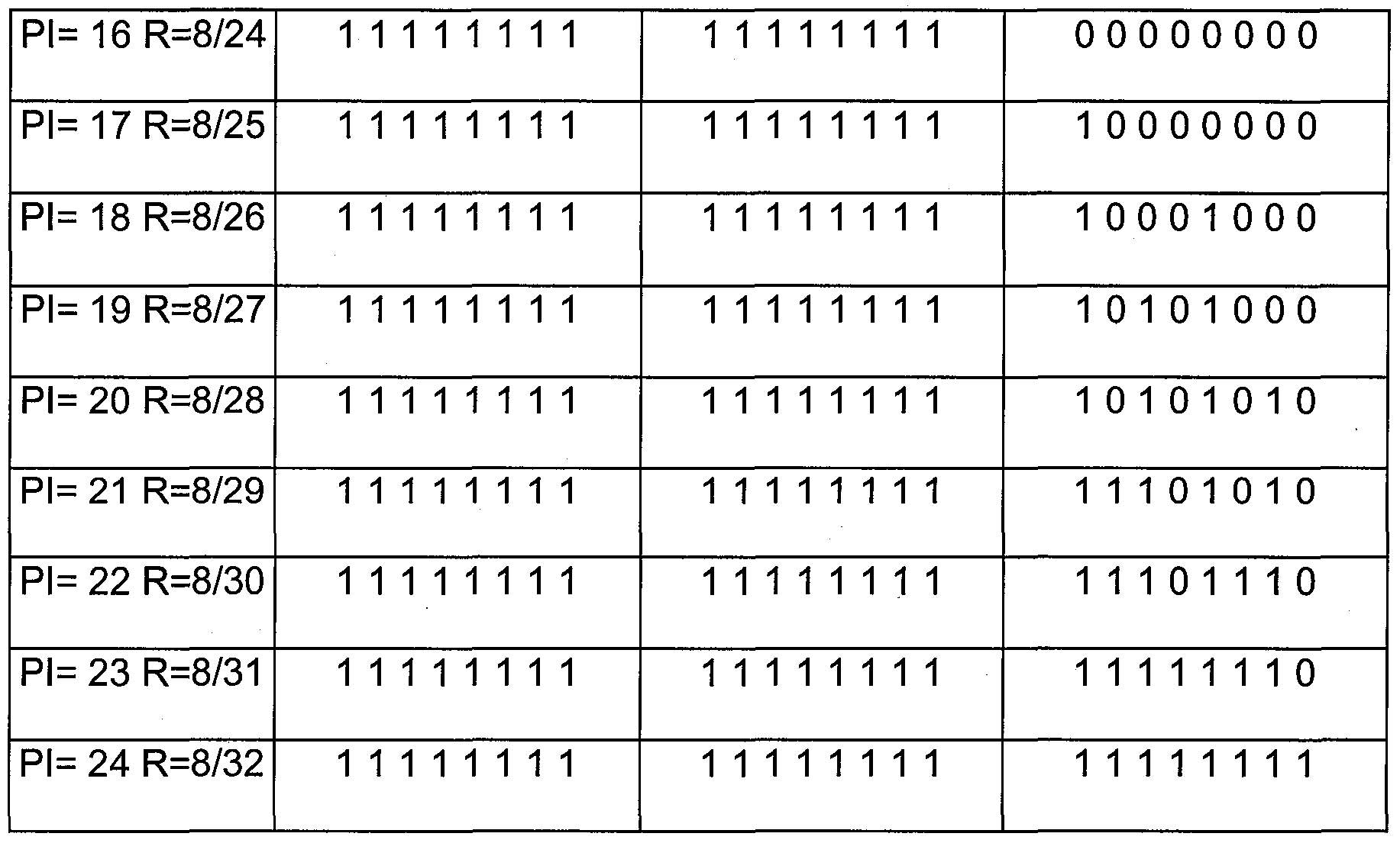
In Table 3, puncturing indexes (Pl=8, 12, 16, 24) are used in the equal error protection of the enhancement layer.
The codeword unit 604 generates a codeword by receiving the parity vectors, in which the puncturing process is performed.
Now, an encoding process applied to the fast information channel (FIC) for the enhancement layer, an encoding process applied to the main service channel (MSC) for the enhancement layer, and an extension process of FIG 0/1 that designates the protection level for the enhancement layer will be described. By using a turbo encoder 502 according to the exemplary embodiment of the invention, the case where the mother coding rate is 1/4 will be described below.
First, the encoding process applied to the fast information channel (FIC) for the enhancement layer will be described.
Four 768-bit logic frames ^Vi = O are transformed to the double-binary
vector
 sequentially having the length N (N=1536) in the output of the
energy dispersal scrambler 501 , and the triple-binary parity vector is generated in the constitution code unit 602 of the turbo encoder 502.
/ nl U Next, the parity vectors VM,i't
 are
are
not punctured in the puncturing unit 603 to be transported, and the parity vectors
(pi U535 (pλ U535
^ 3,Z^i = 0 and v 3,^i = O are punctured in the puncturing unit 603 and are not
( pi \1535 ( pi U535 transported. That is, the parity vectors v/ 3,iΛ = 0 and vr3,i/i = 0 are punctured
based on the puncturing index Pl (Pl=16) defined in Table 3. At this time, the coding rate of the codeword is 1/3 in the FIC.
The output stream of the codeword is represented by a binary vector
Here, the vector (&Λ = o is aligned in order of a 3072-bit encoder input bit vector, a parity bit for an input bit vector, and a parity bit for a permutated input bit vector.
That is, the vector (Ui = o is represented as follow.
/L A9215 _ ( ( e o \3071 ( pi pl )3071 / p2 p2 \3071 1
Next, the encoding process applied to the main service channel (MSC) for the enhancement layer will be described.
Hereinafter, the protection profile and the protection level are defined, and the puncturing process will be described by using these. The protection profile provides blocks of the mother codeword and puncturing indexes
corresponding to each of the blocks.
Unlike the encoding in the base layer, unequal error protection (UEP) is not applied for service components in the enhancement layer due to characteristic of a turbo code and an audio codec to be used. Only equal error protection (EEP) is performed in the enhancement layer.
The protection level 1 indicates the highest protection level in each of profile sets. The base layer supports the data rate having a multiple of 8k and 32k bits/sec, but the enhancement layer supports the data rate having only a multiple of 32k bits/sec. Each logic frame corresponds to one or more data service components
(packet mode) or single service component (stream mode) in the output of the energy dispersal scrambler 501. The service component is composed of the "I" bit vector \ai)i = o, where "I" is a function of the data rate.
Each binary vector (αΛ = o is transformed into K+1 double-binary
vectors
 to be encoded, where 0<=k and I
is an integer of 0<l<4. Each parity P and P2 generated in this case is sequentially aligned to be divided into L blocks composed of 16 triple-binary vectors.
Each of L parity blocks is punctured based on the puncturing index Pl defined in Table 3, and this relation is defined as an equal error protection (EEP) profile of the enhancement layer. The result of turbo encoding with respect to
the given logic frame is represented by a binary vector
 =~ Qλ , where M is a
length.
=~ Qλ , where M is a
length.
When the data rate is a multiple of 32 kbit/s, four protection levels are defined. The four levels P (=1-C,2-C,3-C,4-C) correspond to the coding rates 1/4, 1/3, 2/5, and 1/2, respectively.
Table 4 indicates values of I, K, I, N, and L based on an allowed data rate.
(Table 4)

In Table 4, a maximum data rate is 1.152 Mbit/s. In this case, n is equal to 36, and the length of the codeword with respect to an information bit of 27648 bits and a coding rate of 1/2 is 55296.
Table 5 indicates the data rate and the protection level of the equal error
protection profile. (Table 5)

Finally, an extension method of FIG 0/1 for designating the protection level for enhancement layer will be described.
The protection level of each sub-channel that is transported to the main service channel (MSC) of a terrestrial DMB is designated within the sub-channel configuration field (FIG 0/1 ) that is transported through a fast information channel (FIC). The exemplary embodiment of the invention is characterized in that the enhancement layer is modulated by using the turbo code so as to provide high quality service. In the conventional sub-channel configuration field (FIG 0/1 ), there is no information of protection level and coding rate when the turbo code is used. In addition, an amount of data that is processed at one time, which is designated by the conventional sub-channel configuration field (FIG 0/1 ), is less compared to a case in which the data is processed by using the turbo code. Accordingly, information corresponding to the case in which the turbo code is
used should be added.
According to the exemplary embodiment of the invention, the protection level according to the turbo coding system and the information related thereto are included in the conventional sub-channel configuration field (FIG 0/1 ). FIG. 7 illustrates a structure of a sub-channel configuration field (FIG 0/1 ) according to the invention. According to an exemplary embodiment of the present invention, the structure of the sub-channel configuration field (FIG 0/1) is extended as described below so as to designate the protection level of each sub-channel that is transported through the MSC of the enhancement layer of the hierarchical DMB. A structure of a conventional sub-channel configuration field (FIG 0/1 ) is referred to in section 6.1 of the document ETSI EN 300 401.
Referring to FIG. 7, the sub-channel configuration field (FIG 0/1 ) is configured by a plurality of sub-channels 700. Each sub-channel 700 includes a sub-channel identifier (SubChld) field 701 of 6 bits and a start address field 702 of 10 bits, and a short/long form field 703 and a size and protection field 704 of 1 bit.
The short/long form field 703 represents whether the form used in the size and protection field is a short one or long one. When the short form is used in the size and protection field, a value of the short/long form field is "0". On the other hand, when the long form is used in the size and protection field, a value of the short/long form field is "1 ".
A size and protection field 800 having the short form includes a table switch field 801 of 1 bit and a table index field 802 of 6 bits.
On the other hand, a size and protection field 900 having the long form includes an option field 901 of 3 bits, a protection level field 902 of 2 bits, and a sub-channel size field 903 of 10 bits.
The option field 901 is configured by 3 bits. The option field 901 is used for long-form coding. Conventionally, only "000" and "001" have been used for the equal error protection (EEP). However, according to the exemplary embodiment of the present invention, "010" is additionally used for the equal error protection of MSC of the enhancement layer.
That is, a new variable is added to the option field 901 of the size and protection field 900 having the conventional long form so as to represent the turbo coding rate related to the protection level of the sub-channel at enhancement layer and the number of CUs that are necessary for transportation of sub-channel.
When the value of the option field 901 is "010", the protection level field 902 allocated by 2 bits designates values as follow.
00: protection level 1-C;
01 : protection level 2-C;
10: protection level 3-C;
11 : protection level 4-C. The sub-channel size field 903 designates the number of CUs (range: 1 to 864) that each sub-channel within the MSC occupies according to the data rate. The CU is the smallest unit (64 bits) that can be identified within the MSC.
In Table 6, the turbo coding rate of sub-channel at the enhancement
layer related to each protection level and the number of CUs that are necessary for every data rate allowed by a multiple of 32 kbit/s are shown with respect to four protection levels of the protection level field (02). (Table 6)

Table 6 indicates a size of sub-channel in accordance with a different data rate as a function of a data rate of 32n kbit/s (where n is an integer = 1 ).
The digital-multimedia-broadcasting receiving device according to an exemplary embodiment of the invention will now be described. FIG. 8 is a schematic diagram of a digital-multimedia-broadcasting receiving device according to the exemplary embodiment of the invention, and FIG. 9 is a detailed schematic diagram of a hierarchical DMB receiving unit of FIG. 8.
Referring to FIG. 8, the digital-multimedia-broadcasting receiving apparatus according to the exemplary embodiment of the invention includes a hierarchical DMB receiving unit 10, a base layer receiving processor 20, an enhancement layer receiving processor 30, an MPEG-4 video decoder 40, and an MPEG-4 audio decoder 50. Each component shown in FIG. 8 will be described. As shown in FIG. 9, the hierarchical DMB receiving unit 10 includes an
RF tuner 11 , an A/D converter 12, a fast Fourier transform (FFT) unit 13, a differential demodulator 14, a frequency de-interleaver 15, a symbol demapper 16, a time de-interleaver 17, a convolutional decoder 18, and an energy dispersal descrambler 19. Particularly, the frequency de-interleaver 15 of the hierarchical DMB receiving unit 10 divides a base layer stream and an enhancement layer stream.
The hierarchical DMB receiving unit 10 receives the broadcasting signal, and outputs the base layer transport stream to the base layer receiving processor 20 and the enhancement layer transport stream to the enhancement layer receiving processor 30 through a process corresponding to an inverse of the process of the hierarchical DMB transmitting unit.
The base layer receiving processor 20 performs the channel decoding of the base layer transport stream through the same process as in a conventional digital multimedia broadcasting receiver. The base layer receiving processor 20 performs the channel decoding of the base layer transport stream through processes in a convolutional decoder 21 and an RS decoder 22.
The enhancement layer receiving processor 30 performs the turbo decoding of the enhancement layer transport stream. The enhancement layer receiving processor 30 performs the turbo decoding of the enhancement layer transport stream through processes in a layer symbol demapper 31 , a time de-interleaver 32, a turbo decoder 33, and an energy diverse descrambler 34.
The transport streams of two layers, which are decoded in the base layer receiving processor 20 and in the enhancement layer receiving processor 30,
respectively, are divided into video, audio, and various kinds of additional information packets at TS de-multiplexers 23 and 35. Thereafter, the divided transport streams are extracted to be output through de-packetization and synchronization between the streams at MPEC-4 system decoders 24 and 36, and a video stream and an audio stream of the two layers are extracted to be outputted.
The MPEG-4 video decoder 40 and the MPEG-4 audio decoder 50 perform a process of decoding the video and audio streams of the base layer and the enhancement layer, which are received from the MPEG-4 system decoders 24 and 36, by using the correlation of the two layers, thereby providing high-quality video and audio to users.
When the digital-multimedia-broadcasting receiving apparatus according to the exemplary embodiment of the invention receives a broadcasting signal sent by a conventional system of digital multimedia broadcasting, only a base layer stream is extracted and undergoes the same decoding process as in a conventional digital-multimedia-broadcasting receiving system. Thus, basic-quality video and audio are provided.
The base layer receiving processor 20 is the same component as a conventional digital multimedia broadcasting receiver. The base layer receiving processor 20 includes the convolutional decoder 21 , the RS decoder 22, the TS de-multiplexer 23, and the MPEG-4 system decoder 24, and performs an inverse process with respect to a process of encoding the base layer at the broadcasting transmitting device.
The enhancement layer receiving processor 30 includes the layer symbol de-mapper 31 , the time de-interleaver 32, the turbo decoder 33, the energy diverse descrambler 34, the TS de-multiplexer 35, and the MPEG-4 system decoder 36, and performs an inverse process with respect to a process of encoding the enhancement layer in the broadcasting transmitting device. The exemplary embodiment of the present invention as described above is not necessarily implemented only through the method and apparatus. The exemplary embodiment of the present invention can be realized through a program or through a recording medium on which the program is recorded having a function corresponding to the construction of the exemplary embodiment of the present invention. This modification from the exemplary embodiment of the present invention can be easily realized to a person of ordinary skill in the art.
While this invention has been described in connection with what is presently considered to be practical exemplary embodiments, it is to be understood that the invention is not limited to the disclosed embodiments, but, on the contrary, is intended to cover various modifications and equivalent arrangements included within the spirit and scope of the appended claims. [Industrial Applicability] The present invention can provide a channel encoder for an enhancement layer in a digital-multimedia-broadcasting transmitting device, a digital broadcasting transmitting device, a digital broadcasting receiving device, and an extension structure of a sub-channel configuration field (FIG 0/1 ) for
designating a protection level of sub-channel at the enhancement layer.
Claims
[CLAIMS] [Claim 1 ]
A channel encoder for an enhancement layer of a digital-multimedia-broadcasting transmitting device, which is included in a hierarchical DMB transmitting unit that modulates a base layer transport stream and an enhancement layer transport stream for multimedia data by a base layer modulation system and an enhancement layer modulation system, respectively, and performs symbol mapping of the enhancement layer over the position of a constellation based on the base layer modulation system, wherein the hierarchical DMB transmitting unit comprises: an energy dispersal scrambler that disperses energy of the enhancement layer transport stream; and a turbo encoder that receives a double-binary input vector corresponding to an output of the energy dispersal scrambler and encodes it by using a double-binary circular recursive systematic code.
[Claim 2]
The channel encoder of claim 1 , wherein the turbo encoder comprises: a constituent coding unit that generates a parity vector based on a coding rate of a mother code; and a codeword unit that generates a codeword by using a parity vector and an input vector generated in the constituent coding unit.
[Claim 3]
The channel encoder of claim 2, wherein the constituent coding unit performs a first encoding process that generates a parity vector for the input vector after initializing a circulation state to a first condition, and performs a second encoding process that generates a parity vector for a permutated vector of the input vector after initializing the circulation state to a second condition.
[Claim 4]
The channel encoder of claim 3, wherein the circulation state is determined by a bit string and size of the input vector.
[Claim 5]
The channel encoder of claim 3, wherein the turbo encoder further comprises: a permutation unit that replaces permutation of the input vector by an input bit-inter couple permutation procedure and an input bit-intra couple permutation procedure; and a puncturing unit that performs puncturing of the parity vector generated in the constituent coding unit according to data rate.
[Claim 6]
The channel encoder of claim 5, wherein the puncturing unit divides the parity vector into a plurality of sub-blocks, and the parity vector is punctured according to an element of a puncturing vector with respect to position in each of the sub-blocks.
[Claim 7]
The channel encoder of claim 6, wherein the length of the input vector is determined depending on the data rate, and an allowed length N is 3841, where I is 1 , 2, 3, and 4.
[Claim 8]
The channel encoder of claim 7, wherein when the data rate is less than or equal to 128 kbits/s, and a binary vector (aih = o corresponding to the output
of the energy dispersal scrambler becomes an input vector \χi n = o of the turbo
encoder, where N=l/2, x% ~ \χvxi /, x% ~ a2i, and xi ~ a2i+i.
[Claim 9]
The channel encoder of claim 7, wherein when the data rate is larger than 128 kbits/s, the turbo encoder encodes a plurality of input vectors having a length N (N=1536), respectively, and encodes the rest of double-binary vectors having other lengths that are lower that Ns.
[Claim 10] The channel encoder of claim 2, wherein when the coding rate in the mother code of the turbo encoder is 1/4, the constituent coding unit generates a triple-binary parity vector, and a polynomial expression indicating a connection line of the constituent coding unit is represented as follows:
a feedback branch: 1 + J9+ Z? ; a parity bit M: HD iD ; a parity bit -v 2:
1 + ^3; and a parity bit ^s: l +D+D2+ϋ\
[Claim 11 ]
The channel encoder of claim 10, wherein:
the input vector is (χi)/ = o , τϊ ~ \χi>xi J having a length N; and the input xe is connected to a tab "1 " of a delay element, and the input x° is connected to tabs "1 ", "D", and "D " of a delay element.
[Claim 12] A digital-multimedia-broadcasting transmitting device, comprising: a base layer transmission processing unit that receives a base layer stream, performs system encoding and multiplexing of the received base layer stream, and outputs a base layer transport stream; an enhancement layer transmission processing unit that receives an enhancement layer stream, performs system encoding and multiplexing of the received enhancement layer stream, and outputs an enhancement layer transport stream; and a hierarchical digital-multimedia-broadcasting transmitting unit that modulates the base layer transport stream by a base layer modulation system, modulates the enhancement layer transport stream by a different system from the base layer modulation system, and performs symbol mapping of an enhancement layer according to the position of a constellation based on the base layer modulation system.
[Claim 13]
The digital-multimedia-broadcasting transmitting device of claim 12, wherein the base layer is modulated by a convolutional code system, and the enhancement layer is modulated by a turbo code system.
[Claim 14]
A digital-multimedia-broadcasting receiving device, comprising: a hierarchical digital-multimedia-broadcasting receiver that receives a digital multimedia broadcasting signal and outputs it by dividing the received signal into a base layer transport stream and an enhancement layer transport stream; a base layer receiving processor that performs channel decoding of the base layer stream, de-multiplexes a transport stream, performs system decoding, and outputs a base layer audio and video stream; and an enhancement layer receiving processor that performs turbo decoding of the enhancement layer stream, de-multiplexes a transport stream, performs system decoding, and outputs an enhancement layer audio and video stream.
[Claim 15]
The digital-multimedia-broadcasting receiving device of claim 14, wherein the enhancement layer receiving processor comprises: a symbol de-mapper that performs symbol de-mapping of the enhancement layer stream; a turbo decoder that performs turbo decoding of the symbol de-mapped enhancement layer stream; a de-multiplexer that performs de-multiplexing by dividing the turbo decoded enhancement layer stream into video and audio packets; and a system decoder that performs de-packeting of the de-multiplexing audio and video packet, performs synchronization between streams, and outputs an enhancement layer audio and video stream.
[Claim 16]
An extension structure of sub-channel configuration field (FIG 0/1 ) in a digital-multimedia-broadcasting transmitting device that modulates a base layer transport stream and an enhancement layer transport stream by a base layer modulation system and an enhancement layer modulation system, respectively, and performs symbol mapping of the enhancement layer according to the position of a constellation based on the base layer modulation system, the extension structure comprising: an option field that has a predetermined value for equal error protection of the enhancement layer; and a protection level field that includes protection level information when the value of an option field is the predetermined value.
[Claim 17]
The extension structure of claim 16, wherein the predetermined value is a value when the enhancement layer is modulated by using a turbo code.
[Claim 18]
The extension structure of claim 17, wherein, when the option field is the predetermined value, the protection level field has four protection levels, and a turbo coding rate related to each protection level is 1/4, 1/3, 2/5, and 1/2.
[Claim 19]
The extension structure of claim 18, further comprising a sub-channel size field that designates the number of capacity units (CU), which are the smallest unit that can be identified within a main service channel (MSC), according to a data rate, the capacity units being occupied by each sub-channel within the main service channel, wherein the turbo coding rate of the enhancement layer related to the protection level and the size of sub-channel is as follows:

Priority Applications (2)
| Application Number | Priority Date | Filing Date | Title |
|---|---|---|---|
| CN200880022930A CN101690224A (en) | 2007-05-02 | 2008-05-02 | Apparatus for channel encoding for enhancement layer of digital multimedia broadcasting transmitter, digital multimedia broadcasting transmitter system, digital multimedia broadcasting receiving syste |
| EP08753306.3A EP2145478A4 (en) | 2007-05-02 | 2008-05-02 | Apparatus for channel encoding for enhancement layer of digital multimedia broadcasting transmitter, digital multimedia broadcasting transmitter system, digital multimedia broadcasting receiving system and expansion-form of fig 0/1 |
Applications Claiming Priority (4)
| Application Number | Priority Date | Filing Date | Title |
|---|---|---|---|
| KR20070042661 | 2007-05-02 | ||
| KR10-2007-0042661 | 2007-05-02 | ||
| KR10-2008-0040363 | 2008-04-30 | ||
| KR20080040363A KR20080097929A (en) | 2007-05-02 | 2008-04-30 | Apparatus for channel encoding for enhancement layer of digital multimedia broadcasting transmitter, digital multimedia broadcasting transmitter system, digital multimedia broadcasting receiving system and expansion-form of fig 0/1 |
Publications (1)
| Publication Number | Publication Date |
|---|---|
| WO2008136618A1 true WO2008136618A1 (en) | 2008-11-13 |
Family
ID=41459877
Family Applications (1)
| Application Number | Title | Priority Date | Filing Date |
|---|---|---|---|
| PCT/KR2008/002509 WO2008136618A1 (en) | 2007-05-02 | 2008-05-02 | Apparatus for channel encoding for enhancement layer of digital multimedia broadcasting transmitter, digital multimedia broadcasting transmitter system, digital multimedia broadcasting receiving system and expansion-form of fig 0/1 |
Country Status (3)
| Country | Link |
|---|---|
| EP (1) | EP2145478A4 (en) |
| CN (1) | CN101690224A (en) |
| WO (1) | WO2008136618A1 (en) |
Families Citing this family (2)
| Publication number | Priority date | Publication date | Assignee | Title |
|---|---|---|---|---|
| CN111585703B (en) * | 2015-07-01 | 2023-04-18 | 韩国电子通信研究院 | Broadcast signal receiving apparatus and broadcast signal receiving method |
| CN113395521A (en) * | 2020-03-13 | 2021-09-14 | 华为技术有限公司 | Image encoding and decoding method and device |
Citations (3)
| Publication number | Priority date | Publication date | Assignee | Title |
|---|---|---|---|---|
| WO2006076451A2 (en) * | 2005-01-11 | 2006-07-20 | Qualcomm Incorporated | Methods and apparatus for transmitting layered and non-layered data via layered modulation |
| US20060171283A1 (en) * | 2005-01-11 | 2006-08-03 | Rajiv Vijayan | Method and apparatus for decoding data in a layered modulation system |
| US20060262227A1 (en) * | 2003-08-20 | 2006-11-23 | Young-Ho Jeong | System and method for digital multimedia broadcasting |
Family Cites Families (1)
| Publication number | Priority date | Publication date | Assignee | Title |
|---|---|---|---|---|
| EP1938596A4 (en) * | 2005-09-27 | 2012-03-28 | Korea Electronics Telecomm | Apparatus for transmitting and receiving digital multimedia broadcasting for high-quality video service |
-
2008
- 2008-05-02 WO PCT/KR2008/002509 patent/WO2008136618A1/en active Application Filing
- 2008-05-02 EP EP08753306.3A patent/EP2145478A4/en not_active Withdrawn
- 2008-05-02 CN CN200880022930A patent/CN101690224A/en active Pending
Patent Citations (3)
| Publication number | Priority date | Publication date | Assignee | Title |
|---|---|---|---|---|
| US20060262227A1 (en) * | 2003-08-20 | 2006-11-23 | Young-Ho Jeong | System and method for digital multimedia broadcasting |
| WO2006076451A2 (en) * | 2005-01-11 | 2006-07-20 | Qualcomm Incorporated | Methods and apparatus for transmitting layered and non-layered data via layered modulation |
| US20060171283A1 (en) * | 2005-01-11 | 2006-08-03 | Rajiv Vijayan | Method and apparatus for decoding data in a layered modulation system |
Non-Patent Citations (1)
| Title |
|---|
| See also references of EP2145478A4 * |
Also Published As
| Publication number | Publication date |
|---|---|
| CN101690224A (en) | 2010-03-31 |
| EP2145478A1 (en) | 2010-01-20 |
| EP2145478A4 (en) | 2013-05-29 |
Similar Documents
| Publication | Publication Date | Title |
|---|---|---|
| JP5805673B2 (en) | Encoder and encoding method providing incremental redundancy | |
| CN110719109B (en) | Transmission apparatus and interleaving method thereof | |
| KR100247373B1 (en) | Means and method of improving multiplexed transmission and reception by coding and modulating divided digital signals | |
| US20040101046A1 (en) | Terrestrial digital multimedia/television broadcasting system | |
| JP6437548B2 (en) | Broadcast signal transmitting apparatus, broadcast signal receiving apparatus, broadcast signal transmitting method, and broadcast signal receiving method | |
| WO2012152589A9 (en) | Encoder and encoding method providing incremental redundancy | |
| AU2010321141A1 (en) | Transmitter and transmission method for broadcasting data in a broadcasting system providing incremental redundancy | |
| WO2002017615A2 (en) | Terrestrial digitial multimedia/television broadcasting system | |
| KR20070035409A (en) | Apparatus for Transmitting and Receiving Digital Multimedia Broadcasting for Providing High Quality Video Service | |
| KR101805536B1 (en) | Apparatus for transmitting broadcast signals, apparatus for receiving broadcast signals, method for transmitting broadcast signals and method for receiving broadcast signals | |
| KR20160009048A (en) | Apparatus for transmitting broadcast signals, apparatus for receiving broadcast signals, method for transmitting broadcast signals and mehtod for receiving broadcast signals | |
| EP2100450A1 (en) | Apparatus and method for digital multimedia broadcasting service | |
| US10057101B2 (en) | Apparatus for transmitting broadcast signals, apparatus for receiving broadcast signals, method for transmitting broadcast signals and method for receiving broadcast signals | |
| KR101830741B1 (en) | Apparatus for transmitting broadcast signals, apparatus for receiving broadcast signals, method for transmitting broadcast signals and method for receiving broadcast signals | |
| KR20040035297A (en) | Apparatus and method for transmission of digital broadcasting system having the composition error correction coding function | |
| KR20160012985A (en) | Broadcast signal transmitting device, broadcast signal receiving method, broadcast signal transmitting method and broadcast signal receiving method | |
| EP1938596A1 (en) | Apparatus for transmitting and receiving digital multimedia broadcasting for high-quality video service | |
| KR101790529B1 (en) | Appratus for transmitting broadcast signals, appratus for receiving broadcast signals, method for transmitting broadcast signals, method for receiving broadcast signals | |
| EP2145478A1 (en) | Apparatus for channel encoding for enhancement layer of digital multimedia broadcasting transmitter, digital multimedia broadcasting transmitter system, digital multimedia broadcasting receiving system and expansion-form of fig 0/1 | |
| KR20040034878A (en) | Apparatus and method for transmission of digital broadcasting system which has the composition error correction encoder | |
| KR101652497B1 (en) | System for Terrestrial 4K UHD, HD Convergence Broadcasting using Multiple-PLP and method therefor | |
| KR20080097929A (en) | Apparatus for channel encoding for enhancement layer of digital multimedia broadcasting transmitter, digital multimedia broadcasting transmitter system, digital multimedia broadcasting receiving system and expansion-form of fig 0/1 | |
| Parida et al. | An efficient forward error correction based OFDM technique for digital video broadcasting | |
| EP2405660A1 (en) | Robust in-band signaling for a digital broadcast system | |
| KR20170002187A (en) | Transmitter, receiver and controlling method thereof |
Legal Events
| Date | Code | Title | Description |
|---|---|---|---|
| WWE | Wipo information: entry into national phase |
Ref document number: 200880022930.X Country of ref document: CN |
|
| 121 | Ep: the epo has been informed by wipo that ep was designated in this application |
Ref document number: 08753306 Country of ref document: EP Kind code of ref document: A1 |
|
| WWE | Wipo information: entry into national phase |
Ref document number: 2008753306 Country of ref document: EP |
|
| NENP | Non-entry into the national phase |
Ref country code: DE |