WO2006008683A1 - Method, device, encoder apparatus, decoder apparatus and audio system - Google Patents
Method, device, encoder apparatus, decoder apparatus and audio system Download PDFInfo
- Publication number
- WO2006008683A1 WO2006008683A1 PCT/IB2005/052254 IB2005052254W WO2006008683A1 WO 2006008683 A1 WO2006008683 A1 WO 2006008683A1 IB 2005052254 W IB2005052254 W IB 2005052254W WO 2006008683 A1 WO2006008683 A1 WO 2006008683A1
- Authority
- WO
- WIPO (PCT)
- Prior art keywords
- signal
- stereo
- function
- mix
- complex
- Prior art date
Links
Classifications
-
- H—ELECTRICITY
- H04—ELECTRIC COMMUNICATION TECHNIQUE
- H04S—STEREOPHONIC SYSTEMS
- H04S3/00—Systems employing more than two channels, e.g. quadraphonic
- H04S3/02—Systems employing more than two channels, e.g. quadraphonic of the matrix type, i.e. in which input signals are combined algebraically, e.g. after having been phase shifted with respect to each other
-
- G—PHYSICS
- G10—MUSICAL INSTRUMENTS; ACOUSTICS
- G10L—SPEECH ANALYSIS OR SYNTHESIS; SPEECH RECOGNITION; SPEECH OR VOICE PROCESSING; SPEECH OR AUDIO CODING OR DECODING
- G10L19/00—Speech or audio signals analysis-synthesis techniques for redundancy reduction, e.g. in vocoders; Coding or decoding of speech or audio signals, using source filter models or psychoacoustic analysis
- G10L19/008—Multichannel audio signal coding or decoding using interchannel correlation to reduce redundancy, e.g. joint-stereo, intensity-coding or matrixing
-
- H—ELECTRICITY
- H04—ELECTRIC COMMUNICATION TECHNIQUE
- H04S—STEREOPHONIC SYSTEMS
- H04S1/00—Two-channel systems
- H04S1/007—Two-channel systems in which the audio signals are in digital form
-
- H—ELECTRICITY
- H04—ELECTRIC COMMUNICATION TECHNIQUE
- H04S—STEREOPHONIC SYSTEMS
- H04S2400/00—Details of stereophonic systems covered by H04S but not provided for in its groups
- H04S2400/03—Aspects of down-mixing multi-channel audio to configurations with lower numbers of playback channels, e.g. 7.1 -> 5.1
-
- H—ELECTRICITY
- H04—ELECTRIC COMMUNICATION TECHNIQUE
- H04S—STEREOPHONIC SYSTEMS
- H04S2420/00—Techniques used stereophonic systems covered by H04S but not provided for in its groups
- H04S2420/03—Application of parametric coding in stereophonic audio systems
Definitions
- the invention relates to a method and a device for processing a stereo signal obtained from an encoder, which encodes an N-channel audio signal into spatial parameters and a stereo down-mix signal comprising first and second stereo signals.
- the invention also relates to an encoder apparatus comprising such an encoder and such a device.
- the invention also relates to a method and a device for processing a stereo down-mix signal obtained by such a method and a device for processing a stereo signal obtained from an encoder.
- the invention also relates to a decoder apparatus comprising such a device for processing a stereo down-mix signal.
- the invention also relates to an audio system comprising such an encoder apparatus and such a decoder apparatus.
- Another possibility to reduce the bit rate is by encoding all the individual channels without matrixing. This method results in a higher bit rate, because five channels have to be encoded instead of two, but the spatial reconstruction can be much closer to the original than by applying matrixing. In principle, the matrixing process is a lossy operation. Therefore, perfect reconstruction of the 5 channels from only a 2-channel mix is generally impossible. This property limits the maximum perceptual quality of the 5-channel reconstruction.
- this object is achieved by means of a method of processing a stereo signal obtained from an encoder, which encodes an N-channel audio signal into spatial parameters and a stereo down-mix signal comprising first and second , stereo signals, the method comprising the steps of: adding a first signal and a third signal to obtain a first output signal, wherein said first signal comprises said first stereo signal modified by a first complex function, and wherein said third signal comprises said second stereo signal modified by a third complex function; and adding a second signal and a fourth signal to obtain a second output signal, wherein said fourth signal comprises said second stereo signal modified by a fourth complex function and wherein said second signal comprises said first stereo signal modified by a second complex function; wherein said complex functions are functions of said spatial parameters and are chosen to be such that an energy value of the difference between the first
- the energy value of these difference and sum signals may be based on the 2- norm (i.e. sum of squares over a number of samples) or the absolute value of these signals. Also other conventional energy measures may be applied here.
- the N-channel audio signal comprises front-channel signals and rear-channel signals
- said spatial parameters comprise a measure of the relative contribution of the rear channels in the stereo down-mix as compared to the contribution of the front channels therein. This is because selection of rear-channel contribution is necessary.
- the magnitude of said second complex function may be smaller than the magnitude of said first complex function to enable left/right rear steering and/or the magnitude of said third complex function is smaller than the magnitude of said fourth complex function.
- the second complex function and/or the third complex function may comprise a phase shift, which is substantially equal to plus or minus 90 degrees in order to prevent signal cancellation with front channel contribution.
- said first function comprises first and second function parts, wherein the output of said second function part increases when said spatial parameters indicate that a contribution of the rear channels in said first stereo signal increases as compared to the contribution of the front channels, and said second function part comprises a phase shift which is substantially equal to plus or minus 90 degrees.
- said fourth function may comprise third and fourth function parts, wherein the output of said fourth function part increases when said spatial parameters indicate that the contribution of the rear channels in said second stereo signal increases as compared to the contribution of the front channels, and said fourth function part comprises a phase shift which is substantially equal to plus or minus 90 degrees.
- the first function part may have an opposite sign as compared to said fourth function part.
- the second function may have an opposite sign as compared to said third function.
- the second function and the fourth function part may have the same sign, and the third function and the second function part may have the same sign.
- a device for processing a stereo signal in accordance with the above-mentioned methods, and an encoder apparatus comprising such a device.
- a method is provided for processing a stereo down-mix signal comprising first and second stereo signals, the method comprising the step of inverting the processing operation in accordance with the above-mentioned methods.
- a device for processing a stereo down-mix signal in accordance with the above-mentioned method of processing a stereo down-mix signal, and a decoder apparatus comprising such a device.
- an audio system comprising such an encoder apparatus and such a decoder apparatus.
- Fig. 1 is a block diagram of an encoder/decoder audio system including post- processing and inverse post-processing according to the invention.
- Fig. 2 is a block diagram of an embodiment of a device for processing a stereo signal in accordance with the invention.
- Fig. 3 is a detailed block diagram similar to Fig. 2, showing further details of the invention.
- Fig. 4 is a detailed block diagram similar to Fig. 3, showing still further details of the invention.
- Fig. 5 is a detailed block diagram similar to Fig. 3, showing yet further details of the invention.
- Fig. 6 is a block diagram of an embodiment of a device for processing a stereo down-mix signal in accordance with the invention.
- the inventive method is able to make matrix decoding possible without degrading the parametric multi-channel reconstruction. That is possible because the matrixing techniques are applied in the encoder after down-mixing, in contradiction with usual matrixing, which is done before down-mixing.
- the matrixing of the down-mix is controlled by the spatial parameters.
- the decoder can undo the matrixing based on the transmitted encoder information parameters P.
- matrixing is applied on the original N-channel input signal.
- this approach is not suitable here, since inversion of this matrixing, which is a prerequisite for correct N-channel reconstruction, is generally impossible, because only 2 channels are available at the decoder.
- one feature of this invention is to replace the matrixing technique, which is normally applied on the 5-channel mix, by a parameter- controlled modification of the two-channel mix.
- Fig. 1 is a block diagram of an encoder/decoder audio system incorporating the invention.
- an N-channel audio signal is supplied to an encoder 2.
- the encoder 2 transforms the N-channel audio signal to stereo channel signals L 0 and R 0 and encoder information parameters P, by means of which a decoder 3 can decode the information and approximately reconstruct the original N-channel signal to be output from the decoder 3.
- the N-channel signals may be signals for a 5.1 system, comprising a center channel, two front channels, two surround channels and a Low Frequency Effects (LFE) channel.
- LFE Low Frequency Effects
- the encoded stereo channel signals L 0 and Ro and encoder information parameters P are transmitted or distributed to the user in a suitable way, such as by CD, DVD, broadcast, laser disc, DBS, digital cable, Internet or any other transmission or distribution system, indicated by the circle 4 in Fig. 1. Since the left and right stereo signals L 0 and Ro are transmitted or distributed, the system 1 is compatible with the vast number of receiving equipment that can only reproduce stereo signals. If the receiving equipment includes a parametric multi-channel decoder, the decoder may decode the N-channel signals by providing an estimate thereof on the basis of the information in the stereo channels Lo and Ro as well as the encoder information parameters P.
- N an integer which is larger than 2
- Z 1 [n] , z, [w] , , z N [ n ] describe the discrete time-domain waveforms of the N channels.
- These N signals are segmented by using a common segmentation, preferably using overlapping analysis windows. Subsequently, each segment is converted to the frequency domain, using a complex transform (e.g. FFT).
- complex filter-bank structures may also be appropriate to obtain time/frequency tiles. This process results in segmented, sub-band representations of the input signals, which will be denoted by Z 1 [A:], Z 2 [&] ,...., Z N [k] with & denoting the frequency index.
- Each down-mix channel is a linear combination of the N input signals:
- the parameters cc. and ⁇ t are chosen to be such that the stereo signal consisting of L 0 [h] and R 0 [k] has a good stereo image.
- a post-processor 5 can apply processing in such a way that it mainly affects the contribution of a specific channel i in the stereo mix.
- a specific matrixing technique can be chosen. This results in the left and right matrix-compatible signals L av [k] and R 01 Xk] .
- the post-processed signals Lo w and Ro w may be supplied to a conventional stereo receiver (not shown) for playback.
- the post-processed signals Lo w and Ro w may be supplied to a matrix decoder (not shown), e.g. a Dolby Pro Logic ® decoder or a Circle Surround ® decoder.
- a matrix decoder not shown
- Yet another possibility is to supply the post-processed signals Lo w and Ro w to an inverse post-processor 7 for undoing the processing of the post-processor 5.
- the resulting signals Lo and R 0 can be supplied by the post-processor 7 to a multi- channel decoder 3.
- the device for processing a stereo down-mix signal comprises the inverse post ⁇ processor 7.
- the decoder apparatus according to the invention comprises the decoder 3 and the inverse post-processor 7.
- the N input channels are reconstructed as follows:
- Z 1 Ik] C 12 L 0 [k] + C 2 ⁇ R 0 [k] , where Z 1 [k] is an estimate of Z t [k] .
- the filters C 1 z. and C 2 Z; are preferably time and frequency-dependent, and their transfer functions are derived from the transmitted encoder information parameters P.
- Fig 2 shows how this post-processing block 5 may be embodied to make matrix decoding possible.
- the left input signal L 0 [k] is modified by a first complex function gi, which results in a first signal L OwL [k] which is fed to the left output L 0 JJc] .
- the left input signal L o [k] is also modified by a second complex function g 2 , which results in a second signal R 0 ⁇ 1 Ik] which is fed to the right output R Ow [k] .
- the functions gi and g 2 are chosen to be such that the difference signal L ⁇ 1 - R ⁇ 1 has an equal or larger energy than the sum signal L 0 ⁇ 1 +R OwL • This is because, in the matrix decoding, the ratio of the sum and difference signal is used to perform front/back steering. When the difference signal becomes larger, more input signal is steered to the rear. Because of this R OwL [k] has to increase when the contribution of the left rear in L o [k] increases.
- This control procedure is done by the functions gi andg 2 , which are both functions of the spatial parameters P. These functions are chosen, such that the amount of processing of the left input channel increases when the contribution of the left rear in L 0 [Jc] increases.
- the magnitude of g 2 is preferably smaller than the magnitude of gi. This allows left/right rear steering in the decoder.
- the right input signal R o [k] is modified by a fourth function g 4 , which results in a fourth signal R avR [Jc] , which is fed to the right output R Ow [k] .
- the right input signal R o [k] is also modified by a third function g 3 , which results in a third signal L OwR [Jc] , which is fed to the left output L ⁇ [Jc] .
- the functions g 3 and g 4 are chosen, such that the amount of processing of the right input channel increases when the contribution of the right rear in
- the magnitude of g 3 is preferably smaller than the magnitude of g 4 . This allows left/right rear steering in the decoder.
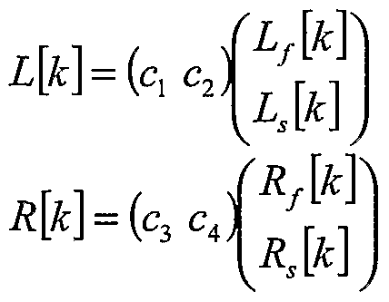
- the output can be described by means of the following matrix equation:
- L 0 [Jc] L[Jc]+ C s [k] in which C s [k] is the mono signal that results after combining the LFE channel and center channel.
- L[Jc] and R[Jc] where L f is the left-front, L s the left-surround, R f the right-front and R s the right-surround channel.
- the constants C 1 to C 4 control the down-mix process and may be complex- valued and/or time and frequency-dependent.
- the parameters ⁇ and ⁇ are determined in the encoder and transmitted to the decoder, i.e. they are a subset of the encoder information parameters P. Additionally, the information signal P may include (relative) signal levels between corresponding front and surround channels, i.e. an Inter-channel Intensity Difference (HD) between L f , L s , and R f , R s , respectively.
- HD Inter-channel Intensity Difference
- the scheme in Fig. 2 can be replaced by the scheme in Fig. 3.
- the parameters HD L and ⁇ are necessary that determine the front/back contribution in the left input channel, which are the parameters HD L and ⁇ .
- the parameters HD R and ⁇ are necessary.
- the function g 2 can now be replaced by the function g 3 , but with an opposite sign.
- functions gi and g 4 are both split into two parallel function parts.
- the function gi is split into gn and g 12 .
- the function g 4 is split into gn and -gi 2 .
- the output signals of the function part gi 2 and the function g 3 are the contributions of the rear channels.
- the function part g 12 and the function g 3 need to be added with the same sign in one output so as to prevent signal cancellation and with opposite sign in the different outputs.
- the function part gi 2 and the function g3 both contain a phase shift of plus or minus 90 degrees. This is to prevent cancellation of the front channel contribution (output of function part g ⁇ ).
- Fig. 5 gives a more detailed description of this block.
- the parameter w determines the amount of processing of L 0 [k] and w r of R 0 [k] .
- L 0 [k] is not processed, and when w, is equal to 1, L 0 [k] is maximally processed.
- w r with respect to R 0 [k] .
- the blocks ⁇ ⁇ 90 are all-pass filters that perform a 90-degree phase shift.
- the blocks G 1 and G 2 in Figure 5 are gains.
- the resulting outputs are:
- the inversion can be done in the decoder without the necessity to transmit additional information, because the parameters W 1 and w r can be calculated from the transmitted parameters. Thus, the original stereo signal will be available again which is necessary for parametric decoding of the multi-channel mix.
- the gains G 1 and G 2 are a function of the inter-channel intensity difference (HD) between the surround channels. In that case, this HD has to be transmitted to the decoder as well.
- HD inter-channel intensity difference
- f x / 4 may be arbitrary functions. For example:
- the all-pass filter ⁇ "90 can be efficiently realized by performing a multiplication in the (complex- valued) frequency domain with the complex operator j
- the determinant of this matrix is equal to:
- G 1 G 2 - the matrix H is always invertible, independent of the values W 1 and w r .
- Figure 6 is a block diagram of an embodiment of the inverse post-processor 7. Like the post-processing, the inversion is done by a matrix multiplication for each frequency band:
- the functions Jc 1 Jc 4 can be determined.
- the functions Jc 1 Jc 4 are functions of the parameter set P, like the functions g, g 4 .
- the functions g l g 4 and the parameter set P therefore need to be known.
- Another application of the invention is to perform the post-processing operation on the stereo signal at the decoder side only (i.e. without post-processing at the encoder side).
- the decoder can generate an enhanced stereo signal from a non-enhanced stereo signal.
- This post-processing operation on the decoder side only may be further elaborated in a situation in which, in the encoder, the multichannel input signal is decoded into a single (mono) signal and associated spatial parameters.
- the mono signal may first be converted into a stereo signal (using the spatial parameters) and thereafter this stereo signal may be post-processed as described above.
- the mono signal may be decoded directly by a multichannel decoder.
Abstract
Description


Claims
Priority Applications (9)
| Application Number | Priority Date | Filing Date | Title |
|---|---|---|---|
| KR1020077000839A KR101147187B1 (en) | 2004-07-14 | 2005-07-07 | Method, device, encoder apparatus, decoder apparatus and audio system |
| US11/571,840 US8150042B2 (en) | 2004-07-14 | 2005-07-07 | Method, device, encoder apparatus, decoder apparatus and audio system |
| JP2007520943A JP4898673B2 (en) | 2004-07-14 | 2005-07-07 | Method, apparatus, encoder apparatus, decoder apparatus, and audio system |
| ES05761091T ES2373728T3 (en) | 2004-07-14 | 2005-07-07 | METHOD, DEVICE, CODING DEVICE, DECODING DEVICE AND AUDIO SYSTEM. |
| PL05761091T PL1769655T3 (en) | 2004-07-14 | 2005-07-07 | Method, device, encoder apparatus, decoder apparatus and audio system |
| CN2005800238555A CN1985544B (en) | 2004-07-14 | 2005-07-07 | Method, device, encoder apparatus, decoder apparatus and system for processing mixed signal of stereo |
| AT05761091T ATE526797T1 (en) | 2004-07-14 | 2005-07-07 | METHOD, APPARATUS, ENCODER, DECODER AND AUDIO SYSTEM |
| EP05761091A EP1769655B1 (en) | 2004-07-14 | 2005-07-07 | Method, device, encoder apparatus, decoder apparatus and audio system |
| US12/882,849 US8144879B2 (en) | 2004-07-14 | 2010-09-15 | Method, device, encoder apparatus, decoder apparatus and audio system |
Applications Claiming Priority (2)
| Application Number | Priority Date | Filing Date | Title |
|---|---|---|---|
| EP04103365 | 2004-07-14 | ||
| EP04103365.5 | 2004-07-14 |
Related Child Applications (2)
| Application Number | Title | Priority Date | Filing Date |
|---|---|---|---|
| US11/571,840 A-371-Of-International US8150042B2 (en) | 2004-07-14 | 2005-07-07 | Method, device, encoder apparatus, decoder apparatus and audio system |
| US12/882,849 Division US8144879B2 (en) | 2004-07-14 | 2010-09-15 | Method, device, encoder apparatus, decoder apparatus and audio system |
Publications (1)
| Publication Number | Publication Date |
|---|---|
| WO2006008683A1 true WO2006008683A1 (en) | 2006-01-26 |
Family
ID=35044993
Family Applications (1)
| Application Number | Title | Priority Date | Filing Date |
|---|---|---|---|
| PCT/IB2005/052254 WO2006008683A1 (en) | 2004-07-14 | 2005-07-07 | Method, device, encoder apparatus, decoder apparatus and audio system |
Country Status (11)
| Country | Link |
|---|---|
| US (2) | US8150042B2 (en) |
| EP (2) | EP2175671B1 (en) |
| JP (2) | JP4898673B2 (en) |
| KR (1) | KR101147187B1 (en) |
| CN (2) | CN1985544B (en) |
| AT (2) | ATE557552T1 (en) |
| ES (2) | ES2373728T3 (en) |
| HK (1) | HK1143481A1 (en) |
| PL (2) | PL2175671T3 (en) |
| TW (1) | TWI462603B (en) |
| WO (1) | WO2006008683A1 (en) |
Cited By (13)
| Publication number | Priority date | Publication date | Assignee | Title |
|---|---|---|---|---|
| WO2007110103A1 (en) * | 2006-03-24 | 2007-10-04 | Dolby Sweden Ab | Generation of spatial downmixes from parametric representations of multi channel signals |
| EP1853093A1 (en) * | 2006-05-04 | 2007-11-07 | LG Electronics Inc. | Enhancing audio with remixing capability |
| WO2008082276A1 (en) * | 2007-01-05 | 2008-07-10 | Lg Electronics Inc. | A method and an apparatus for processing an audio signal |
| JP2008535015A (en) * | 2005-03-30 | 2008-08-28 | コーニンクレッカ フィリップス エレクトロニクス エヌ ヴィ | Audio encoding and decoding |
| KR100891665B1 (en) | 2006-10-13 | 2009-04-02 | 엘지전자 주식회사 | Apparatus for processing a mix signal and method thereof |
| JP2009527970A (en) * | 2006-02-21 | 2009-07-30 | コーニンクレッカ フィリップス エレクトロニクス エヌ ヴィ | Audio encoding and decoding |
| US7672744B2 (en) | 2006-11-15 | 2010-03-02 | Lg Electronics Inc. | Method and an apparatus for decoding an audio signal |
| JP2010510540A (en) * | 2006-11-17 | 2010-04-02 | サムスン エレクトロニクス カンパニー リミテッド | Audio and / or speech signal encoding and / or decoding method and apparatus |
| US7715569B2 (en) | 2006-12-07 | 2010-05-11 | Lg Electronics Inc. | Method and an apparatus for decoding an audio signal |
| US8139775B2 (en) | 2006-07-07 | 2012-03-20 | Fraunhofer-Gesellschaft Zur Foerderung Der Angewandten Forschung E.V. | Concept for combining multiple parametrically coded audio sources |
| US8265941B2 (en) | 2006-12-07 | 2012-09-11 | Lg Electronics Inc. | Method and an apparatus for decoding an audio signal |
| WO2014020182A2 (en) * | 2012-08-03 | 2014-02-06 | Fraunhofer-Gesellschaft zur Förderung der angewandten Forschung e.V. | Decoder and method for a generalized spatial-audio-object-coding parametric concept for multichannel downmix/upmix cases |
| US9418667B2 (en) | 2006-10-12 | 2016-08-16 | Lg Electronics Inc. | Apparatus for processing a mix signal and method thereof |
Families Citing this family (16)
| Publication number | Priority date | Publication date | Assignee | Title |
|---|---|---|---|---|
| US9992599B2 (en) * | 2004-04-05 | 2018-06-05 | Koninklijke Philips N.V. | Method, device, encoder apparatus, decoder apparatus and audio system |
| WO2006008683A1 (en) * | 2004-07-14 | 2006-01-26 | Koninklijke Philips Electronics N.V. | Method, device, encoder apparatus, decoder apparatus and audio system |
| US8793125B2 (en) * | 2004-07-14 | 2014-07-29 | Koninklijke Philips Electronics N.V. | Method and device for decorrelation and upmixing of audio channels |
| EP1899958B1 (en) * | 2005-05-26 | 2013-08-07 | LG Electronics Inc. | Method and apparatus for decoding an audio signal |
| JP4988717B2 (en) | 2005-05-26 | 2012-08-01 | エルジー エレクトロニクス インコーポレイティド | Audio signal decoding method and apparatus |
| KR101512995B1 (en) * | 2005-09-13 | 2015-04-17 | 코닌클리케 필립스 엔.브이. | A spatial decoder unit a spatial decoder device an audio system and a method of producing a pair of binaural output channels |
| KR100803212B1 (en) * | 2006-01-11 | 2008-02-14 | 삼성전자주식회사 | Method and apparatus for scalable channel decoding |
| EP1974346B1 (en) * | 2006-01-19 | 2013-10-02 | LG Electronics, Inc. | Method and apparatus for processing a media signal |
| WO2007091843A1 (en) * | 2006-02-07 | 2007-08-16 | Lg Electronics Inc. | Apparatus and method for encoding/decoding signal |
| US8718290B2 (en) | 2010-01-26 | 2014-05-06 | Audience, Inc. | Adaptive noise reduction using level cues |
| DE102010015630B3 (en) * | 2010-04-20 | 2011-06-01 | Institut für Rundfunktechnik GmbH | Method for generating a backwards compatible sound format |
| US9378754B1 (en) | 2010-04-28 | 2016-06-28 | Knowles Electronics, Llc | Adaptive spatial classifier for multi-microphone systems |
| EP2609589B1 (en) * | 2010-09-28 | 2016-05-04 | Huawei Technologies Co., Ltd. | Device and method for postprocessing decoded multi-channel audio signal or decoded stereo signal |
| CN106104678A (en) * | 2013-10-02 | 2016-11-09 | 斯托明瑞士有限责任公司 | Derive multi channel signals from two or more baseband signals |
| JP5977313B2 (en) * | 2014-10-31 | 2016-08-24 | 住友化学株式会社 | Manufacturing method of polarizing plate |
| GB2549532A (en) * | 2016-04-22 | 2017-10-25 | Nokia Technologies Oy | Merging audio signals with spatial metadata |
Citations (4)
| Publication number | Priority date | Publication date | Assignee | Title |
|---|---|---|---|---|
| EP0858243A2 (en) * | 1997-02-07 | 1998-08-12 | Bose Corporation | Surround sound channel encoding and decoding |
| US5818941A (en) * | 1995-11-22 | 1998-10-06 | Sony Corporation | Configurable cinema sound system |
| US20030210794A1 (en) * | 2002-05-10 | 2003-11-13 | Pioneer Corporation | Matrix surround decoding system |
| US6697491B1 (en) * | 1996-07-19 | 2004-02-24 | Harman International Industries, Incorporated | 5-2-5 matrix encoder and decoder system |
Family Cites Families (21)
| Publication number | Priority date | Publication date | Assignee | Title |
|---|---|---|---|---|
| DE4409368A1 (en) | 1994-03-18 | 1995-09-21 | Fraunhofer Ges Forschung | Method for encoding multiple audio signals |
| US6198827B1 (en) | 1995-12-26 | 2001-03-06 | Rocktron Corporation | 5-2-5 Matrix system |
| US5771295A (en) | 1995-12-26 | 1998-06-23 | Rocktron Corporation | 5-2-5 matrix system |
| US5812971A (en) | 1996-03-22 | 1998-09-22 | Lucent Technologies Inc. | Enhanced joint stereo coding method using temporal envelope shaping |
| US6111958A (en) * | 1997-03-21 | 2000-08-29 | Euphonics, Incorporated | Audio spatial enhancement apparatus and methods |
| US6173061B1 (en) * | 1997-06-23 | 2001-01-09 | Harman International Industries, Inc. | Steering of monaural sources of sound using head related transfer functions |
| WO2000004744A1 (en) | 1998-07-17 | 2000-01-27 | Lucasfilm Ltd. | Multi-channel audio surround system |
| US6463410B1 (en) * | 1998-10-13 | 2002-10-08 | Victor Company Of Japan, Ltd. | Audio signal processing apparatus |
| US6539357B1 (en) | 1999-04-29 | 2003-03-25 | Agere Systems Inc. | Technique for parametric coding of a signal containing information |
| US7212872B1 (en) | 2000-05-10 | 2007-05-01 | Dts, Inc. | Discrete multichannel audio with a backward compatible mix |
| US7292901B2 (en) * | 2002-06-24 | 2007-11-06 | Agere Systems Inc. | Hybrid multi-channel/cue coding/decoding of audio signals |
| CA2473343C (en) | 2002-05-03 | 2012-03-27 | Harman International Industries, Incorporated | Multichannel downmixing device |
| AU2003244932A1 (en) | 2002-07-12 | 2004-02-02 | Koninklijke Philips Electronics N.V. | Audio coding |
| FI118370B (en) * | 2002-11-22 | 2007-10-15 | Nokia Corp | Equalizer network output equalization |
| ATE368921T1 (en) * | 2003-09-29 | 2007-08-15 | Koninkl Philips Electronics Nv | CODING OF AUDIO SIGNALS |
| US9992599B2 (en) | 2004-04-05 | 2018-06-05 | Koninklijke Philips N.V. | Method, device, encoder apparatus, decoder apparatus and audio system |
| US8843378B2 (en) * | 2004-06-30 | 2014-09-23 | Fraunhofer-Gesellschaft Zur Foerderung Der Angewandten Forschung E.V. | Multi-channel synthesizer and method for generating a multi-channel output signal |
| US7391870B2 (en) | 2004-07-09 | 2008-06-24 | Fraunhofer-Gesellschaft Zur Foerderung Der Angewandten Forschung E V | Apparatus and method for generating a multi-channel output signal |
| WO2006008683A1 (en) | 2004-07-14 | 2006-01-26 | Koninklijke Philips Electronics N.V. | Method, device, encoder apparatus, decoder apparatus and audio system |
| US7573912B2 (en) * | 2005-02-22 | 2009-08-11 | Fraunhofer-Gesellschaft Zur Foerderung Der Angewandten Forschunng E.V. | Near-transparent or transparent multi-channel encoder/decoder scheme |
| US7751572B2 (en) * | 2005-04-15 | 2010-07-06 | Dolby International Ab | Adaptive residual audio coding |
-
2005
- 2005-07-07 WO PCT/IB2005/052254 patent/WO2006008683A1/en active Application Filing
- 2005-07-07 EP EP10152627A patent/EP2175671B1/en active Active
- 2005-07-07 KR KR1020077000839A patent/KR101147187B1/en active IP Right Grant
- 2005-07-07 CN CN2005800238555A patent/CN1985544B/en active Active
- 2005-07-07 ES ES05761091T patent/ES2373728T3/en active Active
- 2005-07-07 PL PL10152627T patent/PL2175671T3/en unknown
- 2005-07-07 US US11/571,840 patent/US8150042B2/en active Active
- 2005-07-07 PL PL05761091T patent/PL1769655T3/en unknown
- 2005-07-07 AT AT10152627T patent/ATE557552T1/en active
- 2005-07-07 EP EP05761091A patent/EP1769655B1/en active Active
- 2005-07-07 JP JP2007520943A patent/JP4898673B2/en active Active
- 2005-07-07 ES ES10152627T patent/ES2387256T3/en active Active
- 2005-07-07 CN CN2010102544793A patent/CN102122508B/en active Active
- 2005-07-07 AT AT05761091T patent/ATE526797T1/en not_active IP Right Cessation
- 2005-07-11 TW TW094123382A patent/TWI462603B/en active
-
2010
- 2010-09-15 US US12/882,849 patent/US8144879B2/en active Active
- 2010-09-16 JP JP2010207979A patent/JP5485844B2/en active Active
- 2010-10-13 HK HK10109704.6A patent/HK1143481A1/en unknown
Patent Citations (4)
| Publication number | Priority date | Publication date | Assignee | Title |
|---|---|---|---|---|
| US5818941A (en) * | 1995-11-22 | 1998-10-06 | Sony Corporation | Configurable cinema sound system |
| US6697491B1 (en) * | 1996-07-19 | 2004-02-24 | Harman International Industries, Incorporated | 5-2-5 matrix encoder and decoder system |
| EP0858243A2 (en) * | 1997-02-07 | 1998-08-12 | Bose Corporation | Surround sound channel encoding and decoding |
| US20030210794A1 (en) * | 2002-05-10 | 2003-11-13 | Pioneer Corporation | Matrix surround decoding system |
Cited By (35)
| Publication number | Priority date | Publication date | Assignee | Title |
|---|---|---|---|---|
| JP2008535015A (en) * | 2005-03-30 | 2008-08-28 | コーニンクレッカ フィリップス エレクトロニクス エヌ ヴィ | Audio encoding and decoding |
| JP2009527970A (en) * | 2006-02-21 | 2009-07-30 | コーニンクレッカ フィリップス エレクトロニクス エヌ ヴィ | Audio encoding and decoding |
| JP2009531886A (en) * | 2006-03-24 | 2009-09-03 | ドルビー スウェーデン アクチボラゲット | Spatial downmix generation from parametric representations of multichannel signals |
| CN101406074B (en) * | 2006-03-24 | 2012-07-18 | 杜比国际公司 | Decoder and corresponding method, double-ear decoder, receiver comprising the decoder or audio frequency player and related method |
| US8175280B2 (en) | 2006-03-24 | 2012-05-08 | Dolby International Ab | Generation of spatial downmixes from parametric representations of multi channel signals |
| KR101010464B1 (en) | 2006-03-24 | 2011-01-21 | 코닌클리즈케 필립스 일렉트로닉스 엔.브이. | Generation of spatial downmixes from parametric representations of multi channel signals |
| WO2007110103A1 (en) * | 2006-03-24 | 2007-10-04 | Dolby Sweden Ab | Generation of spatial downmixes from parametric representations of multi channel signals |
| AU2007247423B2 (en) * | 2006-05-04 | 2010-02-18 | Lg Electronics Inc. | Enhancing audio with remixing capability |
| CN101690270B (en) * | 2006-05-04 | 2013-03-13 | Lg电子株式会社 | Method and device for adopting audio with enhanced remixing capability |
| EP1853093A1 (en) * | 2006-05-04 | 2007-11-07 | LG Electronics Inc. | Enhancing audio with remixing capability |
| US8213641B2 (en) | 2006-05-04 | 2012-07-03 | Lg Electronics Inc. | Enhancing audio with remix capability |
| WO2007128523A1 (en) * | 2006-05-04 | 2007-11-15 | Lg Electronics Inc. | Enhancing audio with remixing capability |
| US8139775B2 (en) | 2006-07-07 | 2012-03-20 | Fraunhofer-Gesellschaft Zur Foerderung Der Angewandten Forschung E.V. | Concept for combining multiple parametrically coded audio sources |
| AU2011200669B2 (en) * | 2006-07-07 | 2012-06-28 | Fraunhofer-Gesellschaft Zur Foerderung Der Angewandten Forschung E.V. | Apparatus and method for combining multiple parametrically coded audio sources |
| US9418667B2 (en) | 2006-10-12 | 2016-08-16 | Lg Electronics Inc. | Apparatus for processing a mix signal and method thereof |
| KR100891665B1 (en) | 2006-10-13 | 2009-04-02 | 엘지전자 주식회사 | Apparatus for processing a mix signal and method thereof |
| US7672744B2 (en) | 2006-11-15 | 2010-03-02 | Lg Electronics Inc. | Method and an apparatus for decoding an audio signal |
| JP2010510540A (en) * | 2006-11-17 | 2010-04-02 | サムスン エレクトロニクス カンパニー リミテッド | Audio and / or speech signal encoding and / or decoding method and apparatus |
| US7783049B2 (en) | 2006-12-07 | 2010-08-24 | Lg Electronics Inc. | Method and an apparatus for decoding an audio signal |
| US7783048B2 (en) | 2006-12-07 | 2010-08-24 | Lg Electronics Inc. | Method and an apparatus for decoding an audio signal |
| US7986788B2 (en) | 2006-12-07 | 2011-07-26 | Lg Electronics Inc. | Method and an apparatus for decoding an audio signal |
| US7715569B2 (en) | 2006-12-07 | 2010-05-11 | Lg Electronics Inc. | Method and an apparatus for decoding an audio signal |
| US7783050B2 (en) | 2006-12-07 | 2010-08-24 | Lg Electronics Inc. | Method and an apparatus for decoding an audio signal |
| US7783051B2 (en) | 2006-12-07 | 2010-08-24 | Lg Electronics Inc. | Method and an apparatus for decoding an audio signal |
| US8265941B2 (en) | 2006-12-07 | 2012-09-11 | Lg Electronics Inc. | Method and an apparatus for decoding an audio signal |
| US8311227B2 (en) | 2006-12-07 | 2012-11-13 | Lg Electronics Inc. | Method and an apparatus for decoding an audio signal |
| US8340325B2 (en) | 2006-12-07 | 2012-12-25 | Lg Electronics Inc. | Method and an apparatus for decoding an audio signal |
| US8005229B2 (en) | 2006-12-07 | 2011-08-23 | Lg Electronics Inc. | Method and an apparatus for decoding an audio signal |
| US8428267B2 (en) | 2006-12-07 | 2013-04-23 | Lg Electronics Inc. | Method and an apparatus for decoding an audio signal |
| US8488797B2 (en) | 2006-12-07 | 2013-07-16 | Lg Electronics Inc. | Method and an apparatus for decoding an audio signal |
| US8463605B2 (en) | 2007-01-05 | 2013-06-11 | Lg Electronics Inc. | Method and an apparatus for decoding an audio signal |
| WO2008082276A1 (en) * | 2007-01-05 | 2008-07-10 | Lg Electronics Inc. | A method and an apparatus for processing an audio signal |
| WO2014020182A2 (en) * | 2012-08-03 | 2014-02-06 | Fraunhofer-Gesellschaft zur Förderung der angewandten Forschung e.V. | Decoder and method for a generalized spatial-audio-object-coding parametric concept for multichannel downmix/upmix cases |
| WO2014020182A3 (en) * | 2012-08-03 | 2014-05-30 | Fraunhofer-Gesellschaft zur Förderung der angewandten Forschung e.V. | Decoder and method for a generalized spatial-audio-object-coding parametric concept for multichannel downmix/upmix cases |
| US10096325B2 (en) | 2012-08-03 | 2018-10-09 | Fraunhofer-Gesellschaft Zur Foerderung Der Angewandten Forschung E.V. | Decoder and method for a generalized spatial-audio-object-coding parametric concept for multichannel downmix/upmix cases by comparing a downmix channel matrix eigenvalues to a threshold |
Also Published As
| Publication number | Publication date |
|---|---|
| EP2175671A3 (en) | 2011-01-12 |
| KR20070039543A (en) | 2007-04-12 |
| CN102122508B (en) | 2013-03-13 |
| JP2011039535A (en) | 2011-02-24 |
| EP2175671B1 (en) | 2012-05-09 |
| TW200628002A (en) | 2006-08-01 |
| JP5485844B2 (en) | 2014-05-07 |
| ATE526797T1 (en) | 2011-10-15 |
| HK1143481A1 (en) | 2010-12-31 |
| PL2175671T3 (en) | 2012-10-31 |
| PL1769655T3 (en) | 2012-05-31 |
| CN102122508A (en) | 2011-07-13 |
| ES2387256T3 (en) | 2012-09-19 |
| ATE557552T1 (en) | 2012-05-15 |
| EP1769655B1 (en) | 2011-09-28 |
| EP1769655A1 (en) | 2007-04-04 |
| JP4898673B2 (en) | 2012-03-21 |
| US8150042B2 (en) | 2012-04-03 |
| CN1985544A (en) | 2007-06-20 |
| US8144879B2 (en) | 2012-03-27 |
| US20110058679A1 (en) | 2011-03-10 |
| JP2008537596A (en) | 2008-09-18 |
| US20070230710A1 (en) | 2007-10-04 |
| EP2175671A2 (en) | 2010-04-14 |
| ES2373728T3 (en) | 2012-02-08 |
| KR101147187B1 (en) | 2012-07-09 |
| TWI462603B (en) | 2014-11-21 |
| CN1985544B (en) | 2010-10-13 |
Similar Documents
| Publication | Publication Date | Title |
|---|---|---|
| US8150042B2 (en) | Method, device, encoder apparatus, decoder apparatus and audio system | |
| JP5284638B2 (en) | Method, device, encoder device, decoder device, and audio system | |
| EP1999999B1 (en) | Generation of spatial downmixes from parametric representations of multi channel signals | |
| EP2122613B1 (en) | A method and an apparatus for processing an audio signal | |
| US7394903B2 (en) | Apparatus and method for constructing a multi-channel output signal or for generating a downmix signal | |
| AU2005262025B2 (en) | Apparatus and method for generating a multi-channel output signal | |
| CA2593290C (en) | Compact side information for parametric coding of spatial audio | |
| TW201142825A (en) | Apparatus and method for extracting a direct/ambience signal from a downmix signal and spatial parametric information | |
| EP1817768A2 (en) | Parametric coding of spatial audio with cues based on transmitted channels | |
| MX2008011994A (en) | Generation of spatial downmixes from parametric representations of multi channel signals. |
Legal Events
| Date | Code | Title | Description |
|---|---|---|---|
| AK | Designated states |
Kind code of ref document: A1 Designated state(s): AE AG AL AM AT AU AZ BA BB BG BR BW BY BZ CA CH CN CO CR CU CZ DE DK DM DZ EC EE EG ES FI GB GD GE GH GM HR HU ID IL IN IS JP KE KG KM KP KR KZ LC LK LR LS LT LU LV MA MD MG MK MN MW MX MZ NA NG NI NO NZ OM PG PH PL PT RO RU SC SD SE SG SK SL SM SY TJ TM TN TR TT TZ UA UG US UZ VC VN YU ZA ZM ZW |
|
| AL | Designated countries for regional patents |
Kind code of ref document: A1 Designated state(s): GM KE LS MW MZ NA SD SL SZ TZ UG ZM ZW AM AZ BY KG KZ MD RU TJ TM AT BE BG CH CY CZ DE DK EE ES FI FR GB GR HU IE IS IT LT LU LV MC NL PL PT RO SE SI SK TR BF BJ CF CG CI CM GA GN GQ GW ML MR NE SN TD TG |
|
| DPE1 | Request for preliminary examination filed after expiration of 19th month from priority date (pct application filed from 20040101) | ||
| WWE | Wipo information: entry into national phase |
Ref document number: 2005761091 Country of ref document: EP |
|
| ENP | Entry into the national phase |
Ref document number: 2007520943 Country of ref document: JP Kind code of ref document: A |
|
| WWE | Wipo information: entry into national phase |
Ref document number: 11571840 Country of ref document: US Ref document number: 2007230710 Country of ref document: US |
|
| WWE | Wipo information: entry into national phase |
Ref document number: 1020077000839 Country of ref document: KR |
|
| WWE | Wipo information: entry into national phase |
Ref document number: 200580023855.5 Country of ref document: CN |
|
| NENP | Non-entry into the national phase |
Ref country code: DE |
|
| WWW | Wipo information: withdrawn in national office |
Ref document number: DE |
|
| WWE | Wipo information: entry into national phase |
Ref document number: 575/CHENP/2007 Country of ref document: IN |
|
| WWP | Wipo information: published in national office |
Ref document number: 2005761091 Country of ref document: EP |
|
| WWP | Wipo information: published in national office |
Ref document number: 1020077000839 Country of ref document: KR |
|
| WWP | Wipo information: published in national office |
Ref document number: 11571840 Country of ref document: US |