WO2004060428A1 - Coating for implantable devices and a method of forming the same - Google Patents

Coating for implantable devices and a method of forming the same Download PDF

Info

Publication number
WO2004060428A1
WO2004060428A1 PCT/US2003/038572 US0338572W WO2004060428A1 WO 2004060428 A1 WO2004060428 A1 WO 2004060428A1 US 0338572 W US0338572 W US 0338572W WO 2004060428 A1 WO2004060428 A1 WO 2004060428A1
Authority
WO
WIPO (PCT)
Prior art keywords
stents
primer
coating
region
stent
Prior art date
Application number
PCT/US2003/038572
Other languages
French (fr)
Inventor
Syed F. A. Hossainy
Steven Z. Wu
Manish Gada
Anthony Andreacchi
Original Assignee
Advanced Cardiovascular Systems, Inc.
Priority date (The priority date is an assumption and is not a legal conclusion. Google has not performed a legal analysis and makes no representation as to the accuracy of the date listed.)
Filing date
Publication date
Application filed by Advanced Cardiovascular Systems, Inc. filed Critical Advanced Cardiovascular Systems, Inc.
Priority to AT03796641T priority Critical patent/ATE509641T1/en
Priority to EP03796641A priority patent/EP1575631B1/en
Priority to AU2003298880A priority patent/AU2003298880A1/en
Priority to JP2004565200A priority patent/JP5031989B2/en
Publication of WO2004060428A1 publication Critical patent/WO2004060428A1/en

Links

Classifications

    • AHUMAN NECESSITIES
    • A61MEDICAL OR VETERINARY SCIENCE; HYGIENE
    • A61LMETHODS OR APPARATUS FOR STERILISING MATERIALS OR OBJECTS IN GENERAL; DISINFECTION, STERILISATION OR DEODORISATION OF AIR; CHEMICAL ASPECTS OF BANDAGES, DRESSINGS, ABSORBENT PADS OR SURGICAL ARTICLES; MATERIALS FOR BANDAGES, DRESSINGS, ABSORBENT PADS OR SURGICAL ARTICLES
    • A61L33/00Antithrombogenic treatment of surgical articles, e.g. sutures, catheters, prostheses, or of articles for the manipulation or conditioning of blood; Materials for such treatment
    • A61L33/0005Use of materials characterised by their function or physical properties
    • A61L33/0011Anticoagulant, e.g. heparin, platelet aggregation inhibitor, fibrinolytic agent, other than enzymes, attached to the substrate
    • AHUMAN NECESSITIES
    • A61MEDICAL OR VETERINARY SCIENCE; HYGIENE
    • A61LMETHODS OR APPARATUS FOR STERILISING MATERIALS OR OBJECTS IN GENERAL; DISINFECTION, STERILISATION OR DEODORISATION OF AIR; CHEMICAL ASPECTS OF BANDAGES, DRESSINGS, ABSORBENT PADS OR SURGICAL ARTICLES; MATERIALS FOR BANDAGES, DRESSINGS, ABSORBENT PADS OR SURGICAL ARTICLES
    • A61L27/00Materials for grafts or prostheses or for coating grafts or prostheses
    • A61L27/28Materials for coating prostheses
    • A61L27/34Macromolecular materials
    • AHUMAN NECESSITIES
    • A61MEDICAL OR VETERINARY SCIENCE; HYGIENE
    • A61LMETHODS OR APPARATUS FOR STERILISING MATERIALS OR OBJECTS IN GENERAL; DISINFECTION, STERILISATION OR DEODORISATION OF AIR; CHEMICAL ASPECTS OF BANDAGES, DRESSINGS, ABSORBENT PADS OR SURGICAL ARTICLES; MATERIALS FOR BANDAGES, DRESSINGS, ABSORBENT PADS OR SURGICAL ARTICLES
    • A61L29/00Materials for catheters, medical tubing, cannulae, or endoscopes or for coating catheters
    • A61L29/08Materials for coatings
    • A61L29/085Macromolecular materials
    • AHUMAN NECESSITIES
    • A61MEDICAL OR VETERINARY SCIENCE; HYGIENE
    • A61LMETHODS OR APPARATUS FOR STERILISING MATERIALS OR OBJECTS IN GENERAL; DISINFECTION, STERILISATION OR DEODORISATION OF AIR; CHEMICAL ASPECTS OF BANDAGES, DRESSINGS, ABSORBENT PADS OR SURGICAL ARTICLES; MATERIALS FOR BANDAGES, DRESSINGS, ABSORBENT PADS OR SURGICAL ARTICLES
    • A61L31/00Materials for other surgical articles, e.g. stents, stent-grafts, shunts, surgical drapes, guide wires, materials for adhesion prevention, occluding devices, surgical gloves, tissue fixation devices
    • A61L31/08Materials for coatings
    • A61L31/10Macromolecular materials
    • AHUMAN NECESSITIES
    • A61MEDICAL OR VETERINARY SCIENCE; HYGIENE
    • A61LMETHODS OR APPARATUS FOR STERILISING MATERIALS OR OBJECTS IN GENERAL; DISINFECTION, STERILISATION OR DEODORISATION OF AIR; CHEMICAL ASPECTS OF BANDAGES, DRESSINGS, ABSORBENT PADS OR SURGICAL ARTICLES; MATERIALS FOR BANDAGES, DRESSINGS, ABSORBENT PADS OR SURGICAL ARTICLES
    • A61L31/00Materials for other surgical articles, e.g. stents, stent-grafts, shunts, surgical drapes, guide wires, materials for adhesion prevention, occluding devices, surgical gloves, tissue fixation devices
    • A61L31/14Materials characterised by their function or physical properties, e.g. injectable or lubricating compositions, shape-memory materials, surface modified materials
    • A61L31/16Biologically active materials, e.g. therapeutic substances
    • AHUMAN NECESSITIES
    • A61MEDICAL OR VETERINARY SCIENCE; HYGIENE
    • A61FFILTERS IMPLANTABLE INTO BLOOD VESSELS; PROSTHESES; DEVICES PROVIDING PATENCY TO, OR PREVENTING COLLAPSING OF, TUBULAR STRUCTURES OF THE BODY, e.g. STENTS; ORTHOPAEDIC, NURSING OR CONTRACEPTIVE DEVICES; FOMENTATION; TREATMENT OR PROTECTION OF EYES OR EARS; BANDAGES, DRESSINGS OR ABSORBENT PADS; FIRST-AID KITS
    • A61F2/00Filters implantable into blood vessels; Prostheses, i.e. artificial substitutes or replacements for parts of the body; Appliances for connecting them with the body; Devices providing patency to, or preventing collapsing of, tubular structures of the body, e.g. stents
    • A61F2/82Devices providing patency to, or preventing collapsing of, tubular structures of the body, e.g. stents
    • AHUMAN NECESSITIES
    • A61MEDICAL OR VETERINARY SCIENCE; HYGIENE
    • A61FFILTERS IMPLANTABLE INTO BLOOD VESSELS; PROSTHESES; DEVICES PROVIDING PATENCY TO, OR PREVENTING COLLAPSING OF, TUBULAR STRUCTURES OF THE BODY, e.g. STENTS; ORTHOPAEDIC, NURSING OR CONTRACEPTIVE DEVICES; FOMENTATION; TREATMENT OR PROTECTION OF EYES OR EARS; BANDAGES, DRESSINGS OR ABSORBENT PADS; FIRST-AID KITS
    • A61F2250/00Special features of prostheses classified in groups A61F2/00 - A61F2/26 or A61F2/82 or A61F9/00 or A61F11/00 or subgroups thereof
    • A61F2250/0058Additional features; Implant or prostheses properties not otherwise provided for
    • A61F2250/0067Means for introducing or releasing pharmaceutical products into the body
    • AHUMAN NECESSITIES
    • A61MEDICAL OR VETERINARY SCIENCE; HYGIENE
    • A61LMETHODS OR APPARATUS FOR STERILISING MATERIALS OR OBJECTS IN GENERAL; DISINFECTION, STERILISATION OR DEODORISATION OF AIR; CHEMICAL ASPECTS OF BANDAGES, DRESSINGS, ABSORBENT PADS OR SURGICAL ARTICLES; MATERIALS FOR BANDAGES, DRESSINGS, ABSORBENT PADS OR SURGICAL ARTICLES
    • A61L2300/00Biologically active materials used in bandages, wound dressings, absorbent pads or medical devices
    • A61L2300/60Biologically active materials used in bandages, wound dressings, absorbent pads or medical devices characterised by a special physical form
    • A61L2300/606Coatings
    • AHUMAN NECESSITIES
    • A61MEDICAL OR VETERINARY SCIENCE; HYGIENE
    • A61LMETHODS OR APPARATUS FOR STERILISING MATERIALS OR OBJECTS IN GENERAL; DISINFECTION, STERILISATION OR DEODORISATION OF AIR; CHEMICAL ASPECTS OF BANDAGES, DRESSINGS, ABSORBENT PADS OR SURGICAL ARTICLES; MATERIALS FOR BANDAGES, DRESSINGS, ABSORBENT PADS OR SURGICAL ARTICLES
    • A61L2420/00Materials or methods for coatings medical devices
    • A61L2420/02Methods for coating medical devices

Definitions

  • the invention relates to coatings and methods of forming the coatings on implantable devices or endoluminal prostheses, such as stents.
  • Percutaneous transluminal coronary angioplasty is a procedure for treating heart disease.
  • a catheter assembly having a balloon portion is introduced percutaneously into the cardiovascular system of a patient via the brachial or femoral artery.
  • the catheter assembly is
  • the balloon is advanced through the coronary vasculature until the balloon portion is positioned across the occlusive lesion. Once in position across the lesion, the balloon is inflated to a predetermined size to radially press against the atherosclerotic plaque of the lesion for remodeling of the vessel wall. The balloon is then deflated to a smaller profile to allow the catheter to be withdrawn from
  • a problem associated with the above procedure includes formation of intimal flaps or torn arterial linings which can collapse and occlude the conduit after the balloon is deflated. Vasospasms and recoil of the vessel wall also threaten vessel closure. Moreover, thrombosis and restenosis of the artery may develop over several months after the procedure, which may require another angioplasty procedure or a surgical by-pass operation. To reduce the partial or total
  • an expandable, intraluminal prosthesis one example of which includes a stent, is implanted in the lumen to maintain the vascular patency.
  • Stents are used not only as a mechanical intervention but also as a vehicle for providing biological therapy.
  • stents act as scaffoldings, functioning to physically hold open and, if desired, to expand the wall of the passageway.
  • stents are typically used to provide biological therapy.
  • vascular endothelial stents provide for the local administration of a therapeutic substance at the diseased site. In order to provide an efficacious concentration to the treated site, systemic administration of such medication often produces adverse or toxic side effects for the patient. Local delivery is a preferred method of
  • the embodiments of the present invention provide stent coatings for local delivery of drugs.
  • a method of forming a coating for an implantable device includes forming a primer layer comprising a polymer on at least a portion of a surface of an implantable device, wherein the primer layer has a weight measurement of X, and forming a reservoir layer comprising a polymer and an active
  • the coating has a drug loading equal to or greater than 30%.
  • the method further comprises forming asperities on the surface of the primer layer preceding the formation of the reservoir layer.
  • the primer layer includes at least a region having a degree of porosity.
  • the method includes forming a primer layer comprising a polymer on at least a portion of a
  • the primer layer has a thickness X and forming a reservoir layer comprising a polymer and an active ingredient on at least a selected portion of the primer layer, wherein the reservoir layer has a thickness Y and wherein X/Y is equal to or greater than 0.25.
  • the thickness X is about 0.5 microns to about 3 microns and the thickness Y is about 1 micron to about 10 microns.
  • an implantable device comprising a coating for delivery of an active ingredient.
  • the coating includes a primer region comprising a polymer on at least a portion of a surface of an implantable device, wherein the
  • primer region has a thickness X, and a reservoir region comprising a polymer and an active ingredient on at least a selected portion of the primer region, wherein the reservoir region has a thickness Y, and wherein X/Y is equal to or greater than 0.25.
  • the thickness X is measured from the outer surface of the primer region to the surface of the implantable device prior to the migration of the active ingredient from the reservoir region to the primer region.
  • the coating further includes a barrier region located on at least a selected portion of the reservoir region for reducing the rate at which the active ingredient is released from the coating after insertion of the device into a body of a patient.
  • the primer region includes a porous matrix extending from the interface of the primer region and the reservoir region into the primer.
  • a stent comprising a coating for delivery of an active ingredient is provided, wherein the coating includes a primer region comprising a polymer and a reservoir
  • the primer region is sufficiently high so as to allow drug loading of 30% in the reservoir region
  • FIGS. 1A-1E illustrate coatings in accordance with some of the embodiments of the disclosure
  • FIGS. 2A and 2B illustrate coatings having different layers
  • Figure 3A illustrates a fluid on a solid substrate having a contact angle ⁇ i
  • Figure 3B illustrates a fluid on a solid substrate having a contact angle ⁇ 2 ;
  • Figure 4 graphically illustrates elution profiles for stents with a coating of ethylene vinyl
  • FIG. 5 graphically illustrates in vitro experimental data, in accordance with Example
  • Figure 6A is a picture of a histology slide of a coronary vessel from the control group in
  • Figure 6B is a picture of a histology slide of a coronary vessel from the actinomycin D
  • Figure 7A is a picture of a histology slide of a coronary vessel from the control group in
  • Figure 7B is a picture of a histology slide of a coronary vessel from the actinomycin D
  • Figure 8 A is a Scanning Electron Microscope photograph of a stent coating having a
  • Figure 8B is a Scanning Electron Microscope photograph of a stent coating having a primer layer with ethylene vinyl alcohol copolymer applied in accordance with Example 39
  • Figure 9A is a Scanning Electron Microscope photograph of a stent coating having a primer layer with poly(butyl methacrylate) applied in accordance with Example 39
  • Figure 9B is a Scanning Electron Microscope photograph of a stent coating having a primer layer with poly(butyl methacrylate) applied in accordance with Example 39.
  • DETAILED DESCRIPTION OF THE EMBODIMENTS For ease of discussion, the methods and apparatus detailed herein will be described with reference to a coating for a stent.
  • the implantable device coated in accordance with embodiments of the present invention may be any suitable medical substrate that can be implanted in a human or veterinary patient.
  • implantable devices include self- expandable stents, balloon-expandable stents, stent-grafts, grafts (e.g., aortic grafts), artificial heart valves, cerebrospinal fluid shunts, pacemaker electrodes, and endocardial leads (e.g.,
  • the underlying structure of the device can be of virtually any design.
  • the device can be made of a metallic material or an alloy such as, but not limited to, cobalt chromium alloy (ELGILOY), stainless steel (316L), "MP35N,” “MP20N,” elastinite (Nitinol), tantalum, nickel-titanium alloy, platinum-iridium alloy, gold, magnesium, or combinations thereof.
  • ELGILOY cobalt chromium alloy
  • stainless steel 316L
  • MP35N "MP20N”
  • elastinite Niitinol
  • tantalum nickel-titanium alloy
  • platinum-iridium alloy gold, magnesium, or combinations thereof.
  • MP35N and “MP20N” are trade names for
  • MP35N consists of 35% cobalt, 35% nickel, 20% chromium, and 10% molybdenum.
  • MP20N consists of 50% cobalt, 20% nickel, 20% chromium, and 10% molybdenum.
  • Devices made from bioabsorbable or biostable polymers could also be used with the embodiments of the present invention.
  • a body of a stent 20 is illustrated having a surface 22, e.g., a metallic surface such as stainless steel.
  • a coating 24 is disposed on surface 22.
  • Coating 24 includes a reservoir region 26 containing an active ingredient.
  • a primer region 28 that is substantially free of any active ingredients is disposed underneath at least a portion of reservoir
  • coating 24 can also include a barrier region 30 that is substantially free of any active ingredients.
  • the Figures have not been drawn to scale, and the depth and thickness of the various regions and layers have been over or under emphasized for illustrative purposes.
  • the interface between the primer region and the reservoir region is modified to increase the permeability of the primer layer to the active ingredient.
  • the interface can be modified using one of several methods. These methods include, for example, partially blending of the polymers of the primer region with the polymers of the reservoir region, modifying the surface of the primer layer by forming areas of roughness, or forming a porous matrix on the surface of the primer layer, as more fully described below.
  • the interface between the primer region and the reservoir region can be modified by partially blending the polymers of the primer region with the polymers of the reservoir region during the coating process through the use of a common solvent.
  • primer region 28 can be formed on stent 20 by applying a primer coating composition having a polymer, dissolved in a solvent. Stent 20 can then be baked to essentially remove the solvent in the composition to
  • composition having a polymer, a solvent and an active ingredient dispersed therein. If the solvent in the active ingredient composition is capable of dissolving the polymer in the primer layer, then the polymers of the primer region and the reservoir region will intermix or blend. This blending can allow the active ingredient to be absorbed or flux into primer layer 28.
  • asperities are formed on the surface of the primer layer to increase the permeability of the primer layer.
  • the asperities enable the primer region to physically entrap the reservoir region.
  • the asperities can promote the migration of the active ingredient from the reservoir region to the primer region through capillary action. Because the active ingredient migrates into the deeper portions of the coating, the diffusion rate of the active ingredient from the coating is decreased when the coated device is
  • the asperities can promote an increased residence time of the active ingredient and thereby prevent the "burst effect" of the active ingredient from the coating.
  • Burst effect refers to the quick release of an active ingredient from a polymeric coating when the device is inserted into a biological lumen.
  • the primer region can include a porous matrix extending from the interface of the primer region and the reservoir region into the primer region.
  • the porous matrix can extend partially into the primer region, or all the way up to the surface of the implantable device.
  • the active ingredient can migrate from the reservoir region by capillary action into the primer region.
  • the thickness of the primer region is increased relative to the thickness of the reservoir region.
  • the thicker primer region can be any thicker primer region.
  • the primer region can act as a more effective tie layer between the surface of the device and the reservoir region.
  • the thicker primer region can reduce or prevent the formation of cracks in the stent coating as the stent is expanded as shown
  • primer region 28 can allow for the quantity of the active ingredient in reservoir region 26 to be increased without compromising the ability of reservoir region 26 to be effectively contained on the device during delivery and, if applicable, expansion of the device.
  • the coating of the present invention has superior results when the drug loading is relatively high.
  • the mechanical integrity of the coating of the present invention can withstand expansion of the stent (i.e., the coating does not
  • reservoir region 26 for coating 24 can have a thickness Ti of about 0.5 microns to about 10 microns.
  • Primer region 28 can have a thickness T 2 , examples of which can be in the range of about 0.1 to about 10 microns, more narrowly about 0.5 to about 5 microns.
  • the thickness of the reservoir region Ti is measured from the outer surface of the reservoir region to the primer region prior to the migration of the active ingredient from the reservoir region to the primer region.
  • the thickness of the primer region T 2 is measured from the outer surface of the primer region to the surface of the stent prior to the migration of the active ingredient from the reservoir region to the primer region.
  • T 2 /T 1 is greater than or equal to 0.25.
  • T 2 /T! is greater than or equal to 0.33.
  • the particular thicknesses Ti and T 2 are based in part on the type of procedure for which stent 20 is employed and the amount of the
  • diffusion barrier region 30 can have any suitable thickness T 3 , as
  • the thickness T 3 is dependent on parameters such as, but not limited to, the desired rate or
  • T 3 can have a thickness T 3 of about 0.1 to about 10 microns, more narrowly from about 0.25 to
  • barrier layer 30 can contain particles 32 to
  • the size of particles should not be greater than about 10% of thickness T 3
  • Packing density or particle volume fraction X p can be defined by the following
  • Each of the layers of the polymeric coating can have different sections with different
  • reservoir region 26 can include first and second reservoir
  • sections 26A and 26B each containing a different active ingredient, e.g., actinomycin D and
  • coating 24 can carry a combination of at least two different taxol, respectively. Accordingly, coating 24 can carry a combination of at least two different taxol, respectively. Accordingly, coating 24 can carry a combination of at least two different
  • First and second sections 26A and 26B can be
  • first composition containing a first active ingredient to form first section 26A.
  • section 26A can then be masked and a second composition containing a second active ingredient can be applied to form second section 26B. This procedure can be followed to form any suitable
  • Barrier region 30 can be formed on reservoir sections 26 A and 26B, as illustrated in
  • barrier region 30 can also include a first barrier section 30A
  • first reservoir section 26A containing a first active ingredient, e.g., actinomycin D.
  • a second barrier section 30B can be formed over second reservoir section 26B containing a
  • First barrier section 30A is particle free and second barrier
  • section 30B contains particles 32.
  • coating 24 harbors two different release
  • a coating 34 is provided having a primer region 36, made from
  • a barrier region is deposited on a selected area of primer region 36.
  • reservoir region 38 made from a third polymeric material can be deposited on reservoir region 38.
  • primer with a reservoir layer of ethylene vinylacetate; a poly(n-butyl methacrylate) primer with
  • an ENAL reservoir layer an ENAL primer and a reservoir layer of polycaprolactone; and an
  • epoxy primer consisting of the diglycidylether of bisphenol A cured with polyamine curatives
  • coating 34 contains primer region 36
  • Reservoir region 38 made from a first polymeric material.
  • Reservoir region 38 made from a second polymeric material, is formed on primer region 36.
  • Reservoir region 38 contains first and second sections, illustrated as 38A and 38B.
  • First and second sections 38A and 38B each contain a different
  • Barrier region 40 made from a third polymeric material, can be deposited on
  • Barrier region 40 includes a first section 40 A deposited over first section
  • Barrier region 40 additionally includes a second section 40B
  • Second section 40B can include
  • predetermined amount of a polymer or a prepolymer is added to a predetermined amount of a
  • the mixture can be prepared in ambient pressure and
  • composition for initiating the curing or cross-linking of the prepolymer Heating and stirring
  • Polymer “poly,” and “polymeric” are defined as compounds that are the product of a
  • the polymers should have a
  • Stainless steel such as 316L, is a commonly used material for the manufacturing of a
  • Stainless steel includes a chromium oxide surface layer which makes the stent corrosion
  • suitable polymeric material include polyisocyanates, unsaturated
  • polymers high amine content polymers, acrylates, polymers with high content of hydrogen
  • polyisocyanates include triisocyanurate, alphatic
  • polymethylene polyphenyl isocyanate and polyester polyurethanes.
  • unsaturated polymers include polyester diacrylates,
  • polycaprolactone diacrylates polyester diacrylates, polytetramethylene glycol diacrylate,
  • polyacrylates with at least two acrylate groups polyacrylated polyurethanes, and triacrylates.
  • composition for the thermal or UV curing or cross-linking process for the thermal or UV curing or cross-linking process.
  • thermal curing for thermal curing
  • free radicals initiators are benzoyl peroxide; bis(2,4-dichlorobenzoyl) peroxide;
  • dicumyl peroxide 2,5-bis(tert-butyl peroxy)-2,5-dimethyl hexane; ammonium persulfate, and 2
  • ethyl ether ethyl ether
  • benzophenone ethyl ether
  • These initiators can be activated by illumination with a medium
  • high amine content polymers include polyethyleneamine,
  • acrylates include copolymers of ethyl acrylate, methyl
  • high content of hydrogen bonding group polymers include
  • modified ethylene acrylate polymers methacrylic acid modified ethylene acrylate polymers
  • silane coupling agents include 3 -aminopropyltriethoxy silane
  • titanates include tetra-iso-propyl titanate and tetra-n-butyl
  • zirconates include n-propyl zirconate and n-butyl zirconate.
  • Biocompatible polymers can also be used for the primer material. Examples of
  • biocompatible primers include poly(hydroxyvalerate), poly(L-lactic acid), polycaprolactone,
  • copoly(ether-esters) e.g. PEO/PLA
  • polyalkylene oxalates e.g. polyethylene oxalates
  • polyphosphazenes e.g. polyethylene oxalates
  • biomolecules such as fibrin, fibrinogen, cellulose, starch, collagen and hyaluronic acid.
  • polyurethanes, silicones, and polyesters could be used and other polymers could also be used if they can be dissolved and cured or polymerized on the stent such as polyolefins, polyisobutylene and
  • ethylene-alphaolefin copolymers acrylic polymers and copolymers, vinyl halide polymers and copolymers, such as polyvinyl chloride; polyvinyl ethers, such as polyvinyl methyl ether; polyvinylidene halides, such as polyvinylidene fluoride and polyvinylidene chloride; polyacrylonitrile; polyvinyl ketones; polyvinyl aromatics, such as polystyrene; polyvinyl esters, such as polyvinyl acetate; copolymers of vinyl monomers with each other and olefins, such as ethylene-methyl methacrylate copolymers, acrylonitrile-styrene copolymers, ABS resins, and ethylene- vinyl acetate copolymers; polyamides, such as Nylon 66 and polycaprolactam; alkyd resins; polycarbonates; polyoxymethylenes; polyimides; polyethers; epoxy resins; rayon; rayon
  • a representative example of a very suitable choice of polymer for the primer layer is
  • Ethylene vinyl alcohol is also functionally a very suitable choice of polymer.
  • Ethylene vinyl alcohol copolymer commonly known by the generic name EVOH or by the trade name EVAL, refers to copolymers comprising residues of both ethylene and vinyl alcohol monomers.
  • EVOH generic name
  • EVAL trade name
  • alcohol copolymer may also be a terpolymer so as to include small amounts of additional monomers, for example less than about five (5) mole percentage of styrenes, propylene, or other suitable monomers.
  • the copolymer comprises a mole percent of ethylene of from about 27% to about 47%. Typically, 44 mole percent ethylene is suitable.
  • Ethylene vinyl alcohol copolymers are available commercially from companies such as Aldrich
  • the copolymer possesses good adhesive qualities to the surface of a stent, particularly stainless steel surfaces, and has illustrated the ability to expand with a stent without any significant detachment of the copolymer from the surface of the stent.
  • the solvent should be mutually compatible with the polymer and should be capable of placing the polymer into solution at the concentration desired in the solution. Useful solvents
  • solvent can include, but are not limited to, dimethylsulfoxide (DMSO), chloroform, water (buffered saline), xylene, acetone, methanol, ethanol, 1-propanol, tetrahydrofuran, 1-butanone, dimethylformamide, dimethylacetamide, cyclohexanone, ethyl acetate, methylethylketone, propylene glycol
  • DMSO dimethylsulfoxide
  • chloroform water (buffered saline)
  • xylene acetone
  • methanol ethanol
  • ethanol 1-propanol
  • tetrahydrofuran 1-butanone
  • dimethylformamide dimethylacetamide
  • cyclohexanone ethyl acetate
  • methylethylketone propylene glycol
  • the polymer can comprise from about 0.1% to about 35%, more narrowly about 2% to about 20% by weight of the total weight of the composition, and the solvent can comprise from about 65% to about 99.9%, more narrowly about 80%) to about 98% by weight of the total weight of the composition.
  • a specific weight ratio is dependent on factors such as the material from which the implantable device is made and the geometrical structure of the device.
  • a fluid can also be added to the composition to enhance the wetting of the composition for a more uniform coating application.
  • a suitable fluid typically has a high capillary permeation.
  • Capillary permeation or wetting is the movement of a fluid on a solid substrate driven by interfacial energetics.
  • Capillary permeation is quantitated by a contact angle, defined as an angle at the tangent of a droplet in a fluid phase that has taken an equilibrium shape on a solid surface.
  • a low contact angle means a higher wetting liquid.
  • a suitably high capillary permeation corresponds to a contact angle less than about 90°.
  • Figure 3 A illustrates a fluid droplet 10A on a solid substrate 12, for example a stainless steel
  • Fluid droplet 10A has a high capillary permeation that corresponds to a contact angle
  • Figure 3B illustrates a fluid droplet 10B on solid
  • the wetting fluid typically, should have a viscosity not greater than
  • composition reduces the viscosity of composition.
  • the wetting fluid should be mutually compatible with the polymer and the solvent and
  • the wetting fluid can also act as the solvent.
  • wetting fluid examples include, but are not limited to, tetraliydrofuran (THF),
  • DMF dimethylformamide
  • DMAC dimethyl acetamide
  • the polymer can be any polymer.
  • the polymer can be any polymer.
  • the solvent can comprise from about 19.9% to about
  • the wetting fluid can comprise from about 1% to about 80%, more narrowly from
  • ratio of the wetting fluid depends on the type of wetting fluid employed and type of and the
  • wetting fluid can comprise, for example, from about 1% to about 44%, more narrowly about
  • 1-butanol used as the wetting fluid can comprise, for example, from about 1% to about 33%, more narrowly about 9% by weight of the total weight of the solution.
  • N-butyl acetate used as the wetting fluid can comprise, for example, from about 1% to about 34%o, more narrowly about 14% by weight of the total weight of the solution.
  • Dimethyl acetamide used as the wetting fluid can comprise, for example, from about 1% to about 40%, more narrowly about 20% by weight of the total weight of the solution.
  • Table 1 illustrates some examples of suitable combinations for the primer composition:
  • a predetermined amount of a polymeric compound is added to a predetermined amount of a polymeric compound.
  • polymeric compound can be added at ambient pressure and under anhydrous atmosphere. If
  • polymer into the solvent for example 12 hours in a water bath at about 60°C.
  • the polymer chosen must be a polymer that is biocompatible and minimizes irritation to
  • the polymer may be either a biostable or a
  • Bioabsorbable polymers that could be used include
  • polyanl ydrides poly(glycolic acid), poly(D,L-lactic acid), poly(glycolic acid-co-trimethylene
  • poly(trimethylene carbonate), poly(iminocarbonate), copoly(ether-esters) e.g., PEO/PLA
  • polyalkylene oxalates polyphosphazenes and biomolecules such as fibrin, fibrinogen, cellulose,
  • tissue response such as polyurethanes, silicones, and polyesters could be used and other
  • polymers could also be used if they can be dissolved and cured or polymerized on the stent such
  • polystyrene resin as polystyrene resin, polystyrene resin, polystyrene resin, polystyrene resin, polystyrene resin, polystyrene resin, polystyrene resin, polystyrene resin, polystyrene resin, polystyrene resin, polystyrene resin, polystyrene resin, polystyrene resin, polystyrene resin, polystyrene resin, polystyrene resin, polystyrene resin, polystyrene resin, polystyrene resin, polystyrene resin, polystyrene resin, polystyrene resin, polystyrene resin, polystyrene resin, polystyrene resin, polystyrene resin, polystyrene resin, polystyrene resin, polystyrene resin, polystyrene resin, polystyrene
  • copolymers such as polyvinyl chloride; polyvinyl ethers,
  • polyvinyl methyl ether such as polyvinyl methyl ether
  • polyvinylidene halides such as polyvinylidene fluoride
  • polyvinylidene chloride polyacrylonitrile; polyvinyl ketones; polyvinyl aromatics, such as polystyrene; polyvinyl esters, such as polyvinyl acetate; copolymers of vinyl monomers with
  • olefins such as ethylene-methyl methacrylate copolymers, acrylonitrile-styrene
  • alkyd resins and polycaprolactam; alkyd resins; polycarbonates; polyoxymethylenes; polyimides; polyethers;
  • epoxy resins rayon; rayon-triacetate; cellulose, cellulose acetate, cellulose butyrate; cellulose
  • Ethylene vinyl alcohol is functionally a very suitable choice of polymer.
  • the choice of polymer for the reservoir layer can be the same as or different from the
  • the solvent should be capable of placing the polymer into solution at the concentration
  • solvent can include, but are not limited to, DMSO, chloroform, water (buffered saline), xylene, acetone, methanol, ethanol, 1-propanol, tetrahydrofuran, 1-butanone, dimethylformamide, dimethylacetamide, cyclohexanone, andN- methyl pyrrolidinone.
  • a suitable choice of solvent is iso-propylalcohol (IP A) admixed with water.
  • IP A iso-propylalcohol
  • the active ingredient may be added so that the dispersion is in fine particles.
  • the mixing of the active ingredient can be conducted in an anhydrous atmosphere, at ambient pressure, and at room temperature such that supersaturating the active ingredient is not desired.
  • the active ingredient should inhibit the activity of vascular smooth muscle cells. More specifically, the active ingredient is aimed at inhibiting abnormal or inappropriate migration and/or proliferation of smooth muscle cells.
  • Smooth muscle cells include those cells derived from the medial and adventitial layers of the vessel which proliferate in intimal hyperplastic vascular sites following vascular trauma or
  • smooth muscle cells Under light microscopic examination, characteristics of smooth muscle cells include a histological morphology of a spindle shape with an oblong nucleus located centrally in the cell with nucleoli present and myofibrils in the sarcoplasm. Under electron microscopic examination, smooth muscle cells have long slender mitochondria in the juxtanuclear sarcoplasm, a few tubular elements of granular endoplasmic reticulum, and numerous clusters of free ribosomes. A small Golgi complex may also be located near one pole of the nucleus.
  • “Migration" of smooth muscle cells means movement of these cells in vivo from the medial layers of a vessel into the intima, such as may also be studied in vitro by following the motion of a cell from one location to another, e.g., using time-lapse cinematography or a video
  • “Inhibiting” cellular activity means reducing, delaying or eliminating smooth muscle cell
  • hyperplasia hyperplasia, restenosis, and vascular occlusions, particularly following biologically or
  • trauma or injury means completely “reducing” and/or completely “delaying” intimal hyperplasia
  • restenosis may be determined by methods known to one of ordinary skill in the art, including,
  • Biologically mediated vascular injury includes, but is not limited to, injury caused by or
  • autoimmune disorders attributed to autoimmune disorders, alloimmune related disorders, infectious disorders including endotoxins and herpes viruses such as cytomegalovirus, metabolic disorders such as
  • Mechanically mediated vascular injury includes, but is not limited to, vascular injury caused by catheterization procedures or vascular scraping procedures such as percutaneous transluminal coronary angioplasty, vascular surgery, stent placement, transplantation surgery, laser treatment, and other
  • the active ingredient of the invention is not restricted in use for therapy following vascular injury or trauma; rather, the usefulness of the active ingredient will also be determined by the ingredient's ability to inhibit cellular activity of smooth muscle cells or inhibit the development of restenosis.
  • the active ingredient also includes any substance capable of exerting a therapeutic or
  • the active ingredient can also be for enhancing wound healing in a vascular site and improving the structural and elastic properties of the vascular site.
  • active ingredients include antiproliferative substances as well as antineoplastic, antiinflammatory, antiplatelet, anticoagulant, antifibrin,
  • a suitable example of an antiproliferative substance includes actinomycin D, or derivatives and analogs thereof (manufactured by Sigma-Aldrich 1001 West Saint Paul Avenue, Milwaukee, WI 53233; or COSMEGEN available from Merck). Synonyms of actinomycin D include dactinomycin, actinomycin IV, actinomycin L, actinomycin Xi, and actinomycin Ci. Examples of suitable antineoplastics include paclitaxel and docetaxel.
  • Suitable antiplatelets, anticoagulants, antifibrins, and antithrombins include heparin, sodium heparin, low molecular weight heparin, heparin sulfate, heparin having a hydrophobic counterion, hirudin, argatroban, forskolin, vapiprost, prostacyclin and prostacyclin analogs, dextran, D-phe-pro-arg- chloromethylketone (synthetic antithrombin), dipyridamole, glycoprotein Ilb/Tlla platelet membrane receptor antagonist, recombinant hirudin, thrombin inhibitor (available from Biogen), and 7E-3B® (an antiplatelet drug from Centocore).
  • Suitable antimitotic agents include methotrexate, azathioprine, vincristine, vinblastine, fluorouracil, adriamycin, and mutamycin.
  • suitable cytostatic or antiproliferative agents include angiopeptin (a somatostatin analog from Ibsen), angiotensin converting enzyme inhibitors such as CAPTOPRIL (available from Squibb), CILAZAPRIL (available from Hoffman-LaRoche), or LISINOPRIL (available from Merck); calcium channel blockers (such as Nifedipine), colchicine, fibroblast growth factor (FGF) antagonists, fish oil (omega 3 -fatty acid), histamine antagonist, LOVASTATIN (an inhibitor of HMG-CoA reductase, a cholesterol lowering drug from Merck), monoclonal antibodies (such as PDGF receptors), nitroprusside, phosphodiesterase inhibitors, prostaglandin inhibitor (available form Glazo), Seramin
  • Other therapeutic substances or agents which may be appropriate include mannose-6- phosphate, superoxide dismutase, retinoic acid, suramin, asiaticoside, hyaluronan, alpha- interferon, genetically engineered epithelial cells, dexamethasone and rapamycin and structural derivatives or functional analogs thereof, such as 40-O-(2-hydroxy)ethyl-rapamycin (known by the trade name of EVEROLIMUS available from Novartis), 40-O-(3-hydroxy)propyl-rapamycin, 40-O-[2-(2-hydroxy)ethoxy]ethyl-rapamycin, and 40-O-tetrazole-rapamycin. Exposure of the composition to the active ingredient is not permitted to adversely alter the active ingredient's composition or characteristic. Accordingly, the particular active ingredient is selected for mutual
  • the dosage or concentration of the active ingredient required to produce a favorable therapeutic effect should be less than the level at which the active ingredient produces toxic effects and greater than the level at which non-therapeutic results are obtained.
  • the dosage or concentration of the active ingredient required to inhibit the desired cellular activity of the vascular region can depend upon factors such as the particular circumstances of the patient; the nature of the trauma; the nature of the therapy desired; the time over which the ingredient administered resides at the vascular site; and if other bioactive substances are employed, the nature and type of the substance or combination of substances.
  • Therapeutic effective dosages can be determined empirically, for example by infusing vessels from suitable animal model systems and using immunohistochemical, fluorescent or electron microscopy methods to detect the agent and its effects, or by conducting suitable in vitro studies. Standard pharmacological test procedures to determine dosages are understood by one of ordinary skill in the art.
  • the polymer can comprise from about 0.1% to about 35%, more narrowly from about 2% to about 20% by weight of the total weight of the composition
  • the solvent can comprise from about 59.9% to about 99.8%, more narrowly from about 79% to about 87% by weight of the total weight of the composition
  • the active ingredient can
  • compositions comprise from about 0.1% to about 75%, more narrowly from about 20%> to about 60%) by weight of the total weight of the composition. Selection of a specific weight ratio of the polymer and solvent is dependent on factors such as, but not limited to, the material from which the device is made, the geometrical structure of the device, and the type and amount of the active ingredient employed. The particular weight percentage of the active ingredient mixed within the composition depends on factors such as duration of the release, cumulative amount of release, and release rate that is desired.
  • a second fluid or solvent such as tetrahydrofuran (THF) or dimethylformamide (DMF) can be used to improve the solubility of an active ingredient in the composition and/or to increase the wetting of the composition. Increasing the wetting of the composition has been discovered to lead to the application of a more uniformed coating.
  • the second fluid or solvent can be added to the composition or the active ingredient can be added to
  • the polymer can comprise from about 0.1% to about 35%, more narrowly from about 2% to about 20% by weight of the total weight of the composition
  • the solvent can comprise from about 19.8% to about 98.8%, more narrowly from about 49% to about 79% by weight of the total weight of the composition
  • the second solvent can comprise from about 1% to about 80%>, more narrowly from about 5% to about 40% by weight of the total weight of the composition
  • the active ingredient can comprise from about 0.1 % to about 40%, more narrowly from about 1 % to about 9% by weight of the total weight of the composition.
  • the second solvent is dependent on factors such as, but not limited to, the material from which the implantable device is made, the geometrical structure of the device, and the type and amount of the active ingredient employed.
  • the particular weight percentage of the active ingredient mixed within the composition depends on factors such as duration of the release, cumulative
  • Table 2 is an exemplary list of suitable combinations:
  • composition for The Rate Reducing Membrane The embodiments of the composition for a rate-reducing membrane or diffusion barrier layer are prepared by conventional methods wherein all components are combined. In the embodiment with the use of particles, dispersion techniques should also be employed to circumvent agglomeration or formation of particle floes.
  • the composition for the barrier layer can be applied on a selected portion of the reservoir layer.
  • the barrier layer can reduce the rate of release or delay the time at which the active ingredient is released from the reservoir region.
  • polyethylene glycol or polyethylene oxide can also be added to the blend.
  • Ethylene vinyl alcohol is functionally a very suitable choice of polymer.
  • the copolymer allows for good control capabilities over the release rate of the active ingredient.
  • an increase in the amount of the ethylene comonomer content decreases the rate that the active ingredient is released from the copolymer matrix.
  • the release rate of the active ingredient decreases as the hydrophilicity of the polymer decreases.
  • An increase in the amount of the ethylene comonomer content increases the overall hydrophobicity of the copolymer, especially as the content of vinyl alcohol is concomitantly reduced.
  • the choice of polymer for the barrier layer can be the same as the selected
  • polymer for the reservoir The use of the same polymer can significantly reduce or eliminate interfacial incompatibilities, such as lack of adhesion, which may exist in the employment of two different polymeric layers.
  • Particles of inorganic or organic type can be added to the blend.
  • the particles can be made from any suitable material having barrier-type properties, such as, but not limited to tortuousity, excluded volume, and adsorptivity.
  • Barrier-type properties such as, but not limited to tortuousity, excluded volume, and adsorptivity.
  • Tratuosity refers to the exclusion of space in the polymer matrix for the creation of a defined space or a tortuous path through and about which the active ingredient must travel to be expelled from the layer.
  • Excluded volume refers to the volume displaced by the particles that would otherwise be available for the diffusion of the active ingredient.
  • Adsorptivity refers to the chromatographic effect which is dependent upon
  • the active ingredient may be partially adsorbed and released by the surface of the particles, such as silica or fumed carbon particles.
  • the particles should be dispersed in the blend. "Dispersed” is defined as the particles
  • the particles will disperse with ordinary mixing. Otherwise the particles can be dispersed in the composition by high shear processes such as ball mill, disc mill, sand mill, attritor, rotor stator mixer, ultrasonication ⁇ all such high shear dispersion techniques being well known to one of ordinary skill in the art.
  • one of the aforementioned wetting fluids can also be added to the blend. The wetting fluid can be added prior to, contemporaneously with, or subsequent to the agitation.
  • Biocompatible dispersing agents in the form of surfactants, emulsifiers, or stabilizers may also be added to the blend to assist in particle dispersion.
  • the particles can be made from a metal oxide, such as rutile titanium oxide, anatase titanium dioxide, niobium oxide, tantalum oxide, zirconium oxide, iridium oxide, or tungsten oxide.
  • the particles can be made from a main group oxide such as silica (silicon oxide) or alumina (aluminum oxide).
  • Metallic particles such as gold, hafnium, platinum,
  • iridium, palladium, tungsten, tantalum, niobium, zirconium, titanium, aluminum, or chromium can also be employed.
  • carbonaceous particles made from, for example, lamp black, furnace black, carbon black, fumed carbon black, gas black, channel black, activated charcoal, diamond, diamond like carbon, or CVD diamond can be employed.
  • the particles can be made from nitrides such as titanium nitride, chromium nitride, and zirconium nitride.
  • carbides such as tungsten carbide, silicon carbide, or titanium carbide, and calcium salts such as hydroxyapatite, dahlite, brushite, tricalcium phosphate, calcium sulphate, and calcium carbonate can be used.
  • Other inorganic particles can include particles made from suicides, barium titanate, and strontium titanate.
  • the particles can also be made from a suitable polymer including polymers of
  • polyolefins polyurethanes, cellulosics (i.e., polymers having mer units derived from cellulose), polyesters, polyamides, poly(hexamethylene isophthalamide/terephthalamide) (commercially available as SELAR PATM), polyethylene terephthalate-co-p-oxybenzoate) (PET/PHB, e.g., copolymer having about 60-80 mole percent PHB), poly(hydroxy amide ethers), polyacrylates, polyacrylonitrile, acrylonitrile/styrene copolymer (commercially available as LOP AC), rubber- modified acrylonitrile/acrylate copolymer (commercially available as BAREX), poly(methyl methacrylate), liquid crystal polymers (LCP) (e.g., VECTRA available from Hoescht-Celanese, ZENITE available from DuPont, and XYDAR available from Amoco Performance Chemicals),
  • LCP liquid crystal polymers
  • EVAL e.g., having about 27 to about 47 mole percent of ethylene content
  • polysulfones poly(ester-sulfone), poly(urethane-sulfone), poly(carbonate-sulfone), poly(3-
  • hydroxyoxetane poly(amino ethers), gelatin, amylose, parylene-C, parylene-D, parylene-N.
  • polyolefins include those based upon alpha-monoolefin monomers
  • halogenated olefins having from about 2 to 6 carbon atoms and halogen substituted olefins, i.e., halogenated
  • polystyrene resins polyolefins.
  • low to high density polyethylenes polyethylenes
  • the density can vary according to the supplier.
  • Representative polyurethanes include polyurethanes having a glass transition temperature
  • a storage or ambient temperature for example having a glass transition temperature of at
  • fluorosilicone or mixtures thereof.
  • ELAST-EON manufactured by
  • Elastomedic/CSIRO Molecular Science is a polyurethane with a non-polar soft segment which
  • PDMS bishydroxyethoxypropylpolydimethylsiloxane
  • cellulosics include, but are not limited to, cellulose acetate having a degree of substitution (DS) greater than about 0.8 or less than about 0.6, ethyl cellulose, cellulose nitrate, cellulose acetate butyrate, methyl cellulose, and mixtures thereof.
  • DS degree of substitution
  • polyesters include saturated or unsaturated polyesters such as, but not limited to, poly (butylene terephthalate), poly(ethylene 2,6-naphthalene dicarboxylate) (PEN), and poly (ethylene terephthalate).
  • Representative polyamides include crystalline or amorphous polyamides such as, but not limited to, nylon-6, nylon-6,6, nylon-6,9, nylon-6,10, aromatic nylon MXD6 (manufactured by Mitsubishi Gas Chemical America, Inc.), and mixtures thereof.
  • Representative polyacrylates include, but are not limited to, poly(methylmethacrylate) and polymethacrylate.
  • the particle can be a mixture of the aforementioned polymers.
  • the polymer can comprise about 70% to about 99% by weight acrylonitrile and about 30% to about 1% by weight styrene.
  • the surface of the device or prosthesis should be clean and free from contaminants that may be introduced during manufacturing. However, the surface of the prosthesis requires no particular surface treatment to retain the applied coating. Metallic
  • surfaces of stents can be, for example, cleaned by argon plasma process as is well known to one of ordinary skill in the art.
  • Application of the composition can be by any conventional method, such as by spraying the composition onto the prosthesis or immersing the prosthesis in the composition. Operations such as wiping, centrifugation, blowing, or other web clearing acts can also be performed to achieve a more uniform coating. Briefly, wiping refers to physical removal
  • centrifugation refers to rapid rotation of the stent
  • blowing refers to application of air at a selected pressure to the
  • the excess coating can also be vacuumed off the surface of the device.
  • the coating to be uniformly deposited on the surface of the prosthesis.
  • thermoplastic polymers such as EVAL, polycaprolactone,
  • the deposited primer composition can be any suitable poly(lactide-co-glycolide), poly(hydroxybutyrate), etc.
  • the deposited primer composition can be any suitable poly(lactide-co-glycolide), poly(hydroxybutyrate), etc.
  • T g melting temperature (T g ) and less than about the melting temperature (T m ) of the selected polymer.
  • the device should be exposed to the heat treatment for any suitable duration of time,
  • composition but traces or residues can remain blended with the polymer.
  • Table 3 lists the T g and T m for some of the polymers used in the embodiments of the
  • T g and T m of polymers are attainable by one of ordinary skill in the art.
  • Exact temperature depends on the degree of hydrolysis which is also known as the amount of residual acetate.
  • thermoset polymers With the use of one of the aforementioned thermoset polymers, the use of initiators may be required.
  • epoxy systems consisting of diglycidyl ether of bisphenol A resins can be cured with amine curatives, thermoset polyurethane prepolymers can be cured with polyols, polyamines, or water (moisture), and acrylated urethane can be cured with UV light.
  • the temperature can be above the T g of the selected polymer.
  • the composition containing the prepolymer or precursor is applied and the solvent is allowed to evaporate.
  • surface of the primer can be modified in order to increase the surface area of the primer.
  • asperities, or areas of roughness are created on the surface of the primer layer.
  • a variety of methods can be used to create the asperities on the primer layer covering the outer surface of the prosthesis.
  • a pressurized stream of grit material is directed upon the polymeric primer coating after the primer layer has been dried. Examples of such processes include bead blasting and sand blasting. Bead blasting refers to the use of pressurized gas to project beads of a relatively uniform diameter at an object at a high velocity.
  • the beads may be made of materials such as, but not limited to, aluminum oxide, silicon oxide, or latex.
  • the grit projected does not have as uniform diameter as in bead blasting.
  • bead blasting and sand blasting are techniques that are well known to those of ordinary skill in the art.
  • the roughness achieved using a pressurized grit source can be controlled by the size of the grit, e.g., the diameter of the beads, the pressure used, the distance between the grit source and the primer surface and the length of time the grit is blasted at the
  • the grit can be beads having a diameter of between 10 ⁇ m and 50 ⁇ m. Pressures of 30 PSI (pounds per square inch) to 60 PSI can be used to project the beads from a distance of approximately 3 to 10 cm from the stent.
  • Laser etching can also be used to create asperities or pores on the primer coating after the primer layer has been dried.
  • Laser lithographic methods are known to those of ordinary skill in the art.
  • a laser is directed onto the primer coating for a predetermined period of time, which depends on the etch rate and the depth of etch desired.
  • a patterned mask that has openings may be applied over the primer coating before the laser is utilized. The laser is then allowed to etch the primer through the openings of the mask. The use of patterned masks with laser etchings is
  • the manner in which the primer is deposited onto the outer surface of the stent can create the asperities.
  • the primer may be added via physical deposition processes, for example, by sputtering. Process conditions in which a lower pressure and shorter deposition time than is typically used for thin film deposition are used to form the asperities in the primer coating.
  • the surface of the primer coating can be modified by using a method to form a porous matrix.
  • a porous matrix for the primer coating can be provided, for example, by phase inversion precipitation of a portion of the polymer in the primer layer.
  • a polymer is mixed with two miscible solvents to form a solution.
  • One of the solvents (solvent A) should be less volatile than the other solvent (solvent B).
  • solvent A should be less volatile than solvent
  • solvent B solvent
  • the polymer should be less soluble in solvent A. The solution can then be applied to a portion of the surface of the
  • the polymer matrix becomes porous.
  • the size of the pores can be controlled by the choice of polymers and solvents and the relative concentrations of the solutions.
  • the depth of porous matrix into the primer region can be
  • Pores in the range of about 0.1 microns to about 1 micron in diameter may be suitable.
  • the porous matrix in the primer layer can also be formed by using porogens.
  • a porogen can be added to the primer composition as monodispersed particles to create
  • the porogen particles can comprise from about 5% to about 50% by weight of the total weight of the primer composition.
  • the size of the porogen particles can be about 0.1 microns to 2 microns.
  • porogen particles include sodium chloride and glycine spheres.
  • the appropriate solvent is a compatible solvent for the porogen, but does not substantially dissolve the polymer used to form the primer layer. Water is a representative example of an appropriate solvent if sodium chloride or glycine spheres are used as the porogen.
  • the porous matrix can also be formed by using a sintering process. Sintering is a process of fabrication where particles are bonded together by partially melting some of the particles. For example, a polymeric powder or particles can be applied to the surface of the device and then pressed together. The particles can usefully be about 1 micron to about 10 microns. Then, the polymeric particles can be heated to temperatures slightly below or about the melting point of the polymer. Without entirely melting all of the particles, the particles bond to each other at their respective surfaces. Space remains between the lattice of the particles to form porous
  • composition containing the active ingredient i.e., reservoir layer
  • Masking techniques can be implemented for applying compositions containing different active
  • stents having various cocktail formulations or combinations of a variety of active ingredients can be manufactured.
  • the solvent(s) or the combination of the solvent(s) and the wetting fluid is removed from the composition by allowing the solvent(s) or combination of the solvent(s) and the wetting fluid to
  • the evaporation can be induced by heating the device at a predetermined temperature for a predetermined period of time.
  • the device can be heated at a temperature of about 60°C for about 12 hours to about 24 hours.
  • the heating can be conducted in an anhydrous atmosphere and at ambient pressure and should not exceed the temperature which would adversely affect the active ingredient.
  • the heating can, alternatively, be conducted under a vacuum condition. It is understood that essentially all of the solvent and the wetting fluid will be removed from the composition containing the active ingredient but traces or residues can remain blended with the polymer.
  • a diffusion barrier layer can also be applied on a designated portion of the active
  • the diffusion barrier layer can also be applied by spraying the composition onto the
  • the active ingredient can be applied to a
  • a medical device e.g., a stent, retained on the stent during delivery and expansion of the stent, and
  • a stent having the above-described coating layers is useful for a variety of
  • coating layers is particularly usef l for treating occluded regions of blood
  • Stents may be placed in a wide array of blood vessels, both arteries
  • sites include the iliac, renal, and coronary arteries.
  • embodiments of the coating can be used with a variety of medical substrates.
  • an angiogram is first performed to determine the appropriate positioning for stent
  • Angiography is typically accomplished by injecting a radiopaque contrast agent through
  • a delivery catheter is passed through the lesion or proposed site of treatment. Over the guidewire is passed a delivery catheter
  • the delivery catheter is inserted either percutaneously or by surgery into the femoral artery, brachial
  • a stent having the above described coating regions may then be expanded at the desired area of treatment.
  • insertion angiogram may also be utilized to confirm appropriate positioning.
  • Multi-LinkTM stents (available from Guidant Corporation) were cleaned by placement in
  • Multi-LinkTM stents were dipped in the EVAL solution and then passed over a hot plate, for
  • the coated stents were expanded on a 4.0 mm angioplasty balloon.
  • the coatings were expanded on a 4.0 mm angioplasty balloon. The coatings
  • Multi-LinkTM stents were cleaned by placement in an ultrasonic bath of isopropyl alcohol solution for 10 minutes. The stents were dried and plasma cleaned in a plasma chamber. An EVAL solution was made with 1 gram of EVAL and 4 grams of DMSO, making an EVAL:DMSO ratio of 1 :4. Dexamethasone was added to the 1 :4 EVAL:DMSO solution.
  • Dexamethasone constituted 9% by weight of the total weight of the solution.
  • the solution was vortexed and placed in a tube.
  • the cleaned Multi-LinkTM stents were attached to mandrel wires and dipped into the solution.
  • the coated stents were passed over a hot plate, for about 3-5 seconds, with a temperature setting of about 60°C.
  • the coated stents were cured for 6 hours in an air box and then placed in a vacuum oven at 60°C for 24 hours. The above-recited step was repeated twice.
  • the average weight of the coating was 0.0003 gram, having an estimated dexamethasone content of 75 ug per stent.
  • the coated stents were expanded on a 4.0 mm
  • the coatings remained intact on the stents. Verification of coverage and physical properties of the coatings were visualized using a scanning electron microscope. The coatings were transparent, giving the Multi-LinkTM stents a glossy-like shine.
  • Example 3 Multi-Link DuetTM stents are cleaned by placement in an ultrasonic bath of isopropyl
  • the stents are dried and plasma cleaned in a plasma chamber.
  • the EVAL solution is made with 1 gram of EVAL and 4 grams of DMSO, making an EVAL:DMSO ratio of 1 :4.
  • Dexamethasone is added to the 1 :4 EVAL:DMSO solution.
  • Dexamethasone constitutes 9% by weight of the total weight of the solution.
  • the solution is vortexed and placed in a tube.
  • the cleaned Multi-LinkTM stents are attached to mandrel wires and dipped into the solution.
  • the coated stents are passed over a hot plate, for about 3-5 seconds, with a temperature setting of about 60°C.
  • the coated stents are cured for 6 hours in an air box then placed in a vacuum oven at 60°C for 24 hours.
  • dexamethasone/EVAL coated stents are dipped into the 1 :4 ratio EVAL:DMSO solution, free from dexamethasone.
  • the stents are passed over the hot plate, cured, and placed in the oven as previously described.
  • the top coating will provide a barrier layer for controlling the release of , dexamethasone from the drug coated layer.
  • the coated stents can be expanded on a 4.0 mm
  • the coatings will remain intact on the stents.
  • the coatings will be transparent, giving the Multi-LinkTM stents a glossy-like shine.
  • Example 4 Multi-LinkTM stents were cleaned by placement in an ultrasonic bath of isopropyl alcohol solution for 10 minutes. The stents were dried and plasma cleaned in a plasma chamber. An EVAL solution was made with 1 gram of EVAL and 7 grams of DMSO, making an EVAL:DMSO ratio of 1:7. Vinblastine was added to the 1:7 EVAL:DMSO solution. Vinblastine constituted 2.5% by weight of the total weight of the solution. The solution was vortexed and placed in a tube. The cleaned Multi-LinkTM stents were attached to mandrel wires and dipped into the solution. The coated stents were passed over a hot plate, for about 3-5 seconds, with a temperature setting of about 60°C.
  • the coated stents were cured for 6 hours in an air box then placed in a vacuum oven at 60°C for 24 hours. The above process was repeated twice, having a total of three layers. The average weight of the coating was 0.00005 gram, with an estimated vinblastine concentration of 12 microgram per stent. Some of the stents were
  • the sterilized and unsterilized vinblastine coated stents were tested for a 24 hour elution period by placing one sterilized and one unsterilized stent in 5 ml of phosphated saline solution (pH 7.4) at room temperature with rotational motion.
  • the amount of vinblastine eluted was evaluated by High Performance Liquid Chromatography (HPLC) analysis. The results of this test are given below and plotted in Figure 4. The data indicates that electron beam radiation procedure does not interfere in the release of vinblastine
  • Multi-LinkTM stents were cleaned by placement in an ultrasonic bath of isopropyl alcohol
  • EVAL solution was made with 1 gram of EVAL and 7 grams of DMSO, making an
  • Cephalotaxin constituted 5% by weight of the total weight of the solution.
  • the solution was
  • coated stents were passed over a hot plate, for about 3-5
  • coated stents were cured for 6 hours in
  • the average weight of the coating was 0.00013 gram, with
  • Cephalotaxin/EVAL coated stents and EVAL-coated control stents were implanted in
  • cephalotaxin coated stents in the amount of neointimal proliferation resulting from arterial
  • Multi-Link DuetTM stents (available from Guidant Corporation) were cleaned by
  • EVAL stock solution was made with 1 gram of EVAL and 7 grams of DMSO, making an EVAL:DMSO ratio of 1 :7. The mixture was placed in a warm water shaker bath at 60°C for 12 hours. The solution was mixed, then cooled to room temperature. A co-solvent was added to
  • Multi-Link DuetTM stents were attached to mandrel wires and dipped into the solution.
  • coated stents were passed over a hot plate, for about 3 to 5 seconds, with a temperature setting of about 60°C. The coated stents were then heated in a laboratory oven at 90°C for 4 hours.
  • the thin EVAL coating adhered to stainless steel without peeling or cracking. EVAL forms a superior primer base coat for other polymers that do not adhere well to stainless steel.
  • Multi-Link DuetTM stents were cleaned in an ultrasonic bath of isopropyl alcohol for 20
  • EVAL solution was made with 1 gram of EVAL and 5 grams of DMSO, making an EVAL:DMSO ratio of 1 :5. The mixture was placed in a warm water shaker bath at 60°C for 12 hours. The solution was mixed, then cooled to room temperature. The dissolved EVAL:DMSO solution was mixed with 24.6 grams of THF and 19.56 grams of DMSO. The solution was mixed then placed in the reservoir of an air pressured atomizing
  • Multi-Link DuetTM stents were sprayed while the stents rotated between 30 to 120 rpm.
  • the spray time was dependent upon the flow rate of the sprayer. A flow rate between 1 to 20 mg/second required a stent to be sprayed between 1 to 30 seconds.
  • Link DuetTM stents were heated in a forced air convection oven for 12 hours.
  • the coatings were
  • Multi-Link DuetTM stents were cleaned in an ultrasonic bath of isopropyl alcohol for 20
  • EVAL stock solution was made having an EVAL:DMSO ratio of 1 :4. The mixture was placed in a warm water shaker bath at 60°C for 12 hours. The solution was mixed, then cooled to room temperature.
  • co-solvents were examined to determine which co-solvent would promote a thicker coating. These co-solvents were THF, DMF, 1- butanol, and n-butyl acetate. The formulation for the co-solvents was as follows.
  • DuetTM stents attached to mandrel wires, were dipped into the solutions.
  • the coated stents were
  • Multi-Link DuetTM stents are cleaned in an ultrasonic bath of isopropyl alcohol for 20
  • EVAL stock solution having an EVAL:DMSO ratio of 1 :4.
  • the mixture is placed in a warm water shaker bath at 60°C for 12 hours. The solution is mixed, then cooled to room temperature.
  • a 9% by weight Dexamethasone solution is formulated as follows: 2.96 grams of the EVAL:DMSO solution is mixed with 0.29 gram of Dexamethasone,
  • the coated stents are passed over a hot plate, for about 3 to 5 seconds, with a temperature setting of about 60°C.
  • the coated stents are cured in a forced air convection oven for 2 hours.
  • a second layer of coating is applied and cured in the above
  • Multi-Link DuetTM stents were cleaned in an ultrasonic bath of isopropyl alcohol for 20
  • DuetTM stents were attached to mandrel wires and dipped into the solution.
  • the coated stents were attached to mandrel wires and dipped into the solution. The coated stents
  • the coated stents were cured in a forced air convection oven for 2 hours. A second layer of coating was applied and cured in the above manner.
  • Multi-Link DuetTM stents were cleaned in an ultrasonic bath of isopropyl alcohol for 20
  • EVAL stock solution was made having an EVAL:DMSO ratio of 1 :4. The mixture was placed in a warm water shaker bath at 60°C for 12 hours. The solution was mixed, then cooled to room temperature. A 3.60% by weight actinomycin D solution was formulated as follows: 600 milligrams of the EVAL:DMSO solution was mixed with 40 milligrams of actinomycin D, then 480 milligrams of DMF was added. The cleaned Multi-Link
  • DuetTM stents were attached to mandrel wires and dipped into the solution.
  • the coated stents were attached to mandrel wires and dipped into the solution. The coated stents
  • coated stents were cured in a forced air convection oven for 2 hours.
  • a second layer of coating was applied and cured in the above manner.
  • Multi-Link DuetTM stents were cleaned in an ultrasonic bath of isopropyl alcohol for 20
  • EVAL stock solution was made having an EVAL:DMSO ratio of 1 :4. The mixture was placed in a warm water shaker bath at 60°C for 12 hours. The solution was mixed, then cooled to room temperature. A 6.45%> by weight actinomycin D solution was formulated as follows: 680 milligrams of the EVAL:DMSO solution was mixed with 80 milligrams of actinomycin D, then 480 milligrams of DMF was added. The cleaned Multi-Link
  • DuetTM stents were attached to mandrel wires and dipped into the solution.
  • the coated stents were attached to mandrel wires and dipped into the solution. The coated stents
  • coated stents were cured in a forced air convection oven for 2 hours.
  • Multi-Link DuetTM stents are cleaned in an ultrasonic bath of isopropyl alcohol for 20
  • EVAL stock solution having an EVAL:DMSO ratio of 1 :40.
  • the mixture is placed in a warm water shaker bath at 60°C for 12 hours.
  • the solution is mixed,
  • actinomycin D solution can be formulated
  • the coated stents are cured in a forced air
  • SMC Medial smooth muscle cells
  • actinomycin D mytomycin and docetaxel.
  • the cells were exposed to the drug solution of different concentrations for 2 hours and then washed with buffered saline solution.
  • the proliferation of the cells was quantified by standard technique of thymidine incorporation.
  • the IC 5 o (concentration at which 50% of the cells stop proliferating) of actinomycin D was 10 "9 M as compared to 5 x 10 "5 M for mitomycin and 10 "6 M for docetaxel. Actinomycin D was the most potent agent to prevent SMC proliferation as compared to other pharmaceutical
  • Example 16 Reduction in Restenosis in the Porcine Coronary Artery Model
  • Porcine coronary models were used to assess the degree of the inhibition of neointimal formation in the coronary arteries of a porcine stent injury model by Actinomycin D, delivered with a microporous balloon catheter (lxl 0 6 pores/mm 2 with sizes ranging from 0.2-0.8 micron).
  • the preclinical animal testing was performed in accordance with the NIH Guide for Care and Use of Laboratory Animals. Domestic swine were utilized to evaluate effect of the drug on the inhibition of the neointimal formation.
  • Each testing procedure, excluding the angiographic analysis at the follow-up endpoints, was conducted using sterile techniques. During the study
  • ACT activated clotting time
  • Base line blood samples were collected for each animal before initiation of the procedure.
  • Quantitative coronary angiographic analysis (QCA) and intravascular ultrasound (rVUS) analysis was used for vessel size assessment.
  • the vessels at the sites of the delivery were denuded by inflation of the PTCA balloons to 1 : 1 balloon to artery ratio and moving the balloons back and forth 5 times.
  • the drug was delivered to the denuded sites at 3.5 atm (3.61 Kg/sq cm) for 2 minutes using the microporous balloon catheters before stent deployment.
  • the average volume of delivery was about 3.3 +/- 1.2 ml.
  • stents were deployed at the delivery site such that final stent to artery ratio was 1.1:1.
  • angiographic assessments were performed. Coronary artery blood flow was assessed and the stented vessels were evaluated to determine minimal lumen diameter. The animals were euthanized following this procedure at the endpoint. Following euthanasia, the hearts were pressure perfusion fixed with formalin and prepared for histological analysis, encompassing light microscopy, and morphometry. Morphometric analysis of the stented arteries included assessment of the position of the stent struts and determination of vessel/lumen areas, percent (%) stenosis, injury scores,
  • the control group of animals received delivery of water instead of the drug.
  • the test group of animals received actinomycin D in two different concentration of 10 "5 M and lO ⁇ M.
  • the results of the study are tabulated in Table 4.
  • the percent stenosis in the treated groups (32.3 +/- 11.7) was significantly decreased as compared to the control groups (48.8 +/- 9.8).
  • 6 A and 6B illustrate sample pictures of the histology slides of the coronary vessels from the
  • actinomycin D is useful for the treatment of hyper-proliferative vascular disease. Specifically,
  • actinomycin D is useful for the inhibition of smooth muscle cell hyperplasia, restenosis and
  • vascular occlusion in a mammal particularly occlusions following a mechanically mediated
  • Multi-Link DuetTM stents 13 mm in length were cleaned in an ultrasonic bath of
  • EVAL stock solution was made having an EVAL:DMSO ratio of 1 :4. The mixture was placed in a warm water shaker bath at 60°C for 12
  • actinomycin D solution was formulated as follows: 40 milligrams of actinomycin D was
  • coated stents were passed over a hot plate, for about 3 to 5 seconds, with a temperature
  • Multi-Link DuetTM stents 13 mm in length were cleaned in an ultrasonic bath of
  • actinomycin D solution was formulated as follows: 60 milligrams of actinomycin D was
  • coated stents were passed over a hot plate, for about 3 to 5 seconds, with a
  • Multi-Link DuetTM stents were cleaned in an ultrasonic bath of isopropyl alcohol for 20
  • coated stents were
  • coating weight of about 250 micrograms and an average actinomycin D loading of about 75
  • Multi-Link DuetTM stents are cleaned in an ultrasonic bath of isopropyl alcohol for 20
  • EVAL stock solution having an EVAL:DMSO ratio of 1 :40.
  • the mixture is placed in a warm water shaker bath at 60°C for 12 hours.
  • the solution is mixed,
  • actinomycin D solution can be formulated
  • the coated stents are cured in a forced air
  • a stainless steel stent can be spray coated with a formulation of EVAL and a drug, as
  • a diffusion barrier composition can be any of the above examples.
  • a diffusion barrier composition can be any of the above examples.
  • fumed silica can be added and dispersed with a high shear process. With constant agitation, 50
  • stent having the EVAL coating
  • the diffusion barrier composition can be immersed in the diffusion barrier composition to form a
  • Example 22 A stainless steel stent can be spray coated with a formulation of EVAL and a drug, as
  • a diffusion barrier formulation can be made
  • the particles can be dispersed
  • a stainless steel stent can be coated with a formulation of EVAL and a drug, as
  • a diffusion barrier formulation can be made
  • precipitated hydroxyapatite can be added to the blend.
  • the particles can be dispersed using a
  • a stent can be coated with a formulation of EVAL and a drug, as previously described in
  • the polymer can be dissolved by agitation and heat. Four grams of lamp black can be added and
  • the stent can be spray coated.
  • a stent can be coated with a formulation of EVAL and a drug, as previously described in
  • Colloidal gold can be prepared by reduction of tetrachloroauric acid
  • actinomycin D Stents coated with EVAL impregnated with actinomycin D and a control group
  • the index of remodeling was 1.076 (8.54/7.94).
  • FIGs 7 A and 7B illustrate sample pictures of the histology slides of the coronary vessels from the control group 64 RCA (Right Coronary Group) and the actinomycin D loaded stent group 68 LAD (Left Anterior Descending), respectively.
  • the stent used was an Advanced
  • Thrombus deposits can be, accordingly, eliminated.
  • Actinomycin D induces the positive remodeling of the vessel walls, more particularly positive remodeling of the external elastic lamina (EEL) of a blood vessel wall.
  • Positive remodeling is generally defined as the ability of the vessel walls to structurally adapt, by increasing in lumen size, to chronic stimuli.
  • a positively remodeled lumen wall has a greater diameter or size as compared to a lumen wall which has not been subjected to the remodeling effect. Accordingly, the flow of blood through the remodeled site is increased ⁇ flow which would have otherwise been reduced because of, for example, the presence of plaque build-up or migration and proliferation of cells.
  • the index of remodeling is defined by the ratio of the area circumscribed by the EEL of the lesion site to the area circumscribed by the EEL of a reference site.
  • the internal elastic lamina in response, can also increases in area or diameter.
  • Actinomycin D, or analogs or derivative thereof not only can inhibit abnormal or inappropriate migration and/or proliferation of smooth muscle cells, which can lead to restenosis, but can also induce positive remodeling of the blood vessel walls. Thus the widening of the diseased region becomes more pronounced.
  • the stent can be cured for 5 minutes under medium pressure mercury
  • thermoset resin 1.67 grams of Epon 828 (Shell) resin can be added to 98 grams
  • the stent can be baked for 2 hours at 80°C and 2 hours at 160°C.
  • a 0.25% (w/w) solution of tetra-n-butyl titanate can be made in anhydrous ethyl acetate.
  • the solution can be applied by spraying to a surface of a stainless steel stent.
  • the stent can be
  • tortuosity tree (2.5 mm lumen at entrance, 1.5 mm lumen at exit).
  • CER environment room
  • the test was performed to observe the coating integrity after a simulated delivery to a
  • the primer layer improved coating adhesion to the stents that
  • Group B had a number defects.
  • coating surface for Group B was poor to begin with, and the defects were not too severe.
  • surface treatments consisted of: (1) Argon plasma treatment; and (2) Argon plasma treatment
  • the test method used to test adhesion of coatings on stents was a wet flow test
  • Plasma Machine available from Advanced Plasma System
  • Count defects based on the following categories: Defect type; defect size; defect location; and peel defects on rings 3, 5, and 7.
  • Stent weight could not be a measurable because of the loss of the drug and uptake of water.
  • Peel defects are defined as areas where the coating separated from the stent. The number of peel defects were counted on the stents' OD/sidewall on rings 3, 5, and 7. The flow field was on the inner diameter ("ID") of the stents' surface. Some of the damage to the OD surface could have been aggravated by the Tecoflex tubing. The number of peel defects observed on groups C and F (EVAL primer) was clearly lower than the other two test groups, regardless of flow rate. The increased flow rate did not induce more peel defects.
  • ID inner diameter
  • the objective of this experiment was to test the adhesive properties of an Actinomycin-D
  • coated stents containing coating on stainless steel stents having an EVAL primer layer.
  • a "peel defect” is defined as a location on the
  • stent surface devoid of coating, i.e., bare metal or underlying coating layer that is visible under
  • optical magnification of less than lOOx optical magnification of less than lOOx.
  • Plasma Machine Advanced Plasma System
  • Vlll Weighed each sample at the end of the last pass to the nearest microgram.
  • a "peel defect” is defined as a location on the stent
  • optical magnification of no more than lOOx
  • Stent weight could not be a measurable because of the loss of the drug and uptake of
  • the spray-coated primer produced slightly higher peel defect counts compared to the dip-spin
  • the objective of this experiment was to test the adhesive properties of an Actinomycin-D
  • coated stents were tested under wet flow conditions of saline heated to 37°C. The number of
  • Group B i. Placed samples flat on sample holder. Perform argon plasma treatment.
  • Group C i. Placed the samples flat on sample holder. Perform argon plasma
  • Group D i. Placed samples flat on sample holder. Perform argon plasma treatment. ii. Spray coated primer layer (2% EVAL, 1 : 1 DMF:DMSO) onto stents.
  • Stent weight could not be a measurable because of the loss of the drug and uptake of
  • control group with no primer layer had significantly more peel defects as compared
  • the objective of this experiment was to test the adhesive properties of an Actinomycin-D

Abstract

Coatings for implantable devices or endoluminal prosthesis, such as stents, are provided, including a method of forming the coatings. The coatings can be used for the delivery of an active ingredient or a combination of active ingredients.

Description

COATING FOR IMPLANTABLE DEVICES AND A METHOD OF FORMING
THE SAME BACKGROUND Field of the Invention The invention relates to coatings and methods of forming the coatings on implantable devices or endoluminal prostheses, such as stents.
Description of the Background
Percutaneous transluminal coronary angioplasty (PTCA) is a procedure for treating heart disease. A catheter assembly having a balloon portion is introduced percutaneously into the cardiovascular system of a patient via the brachial or femoral artery. The catheter assembly is
advanced through the coronary vasculature until the balloon portion is positioned across the occlusive lesion. Once in position across the lesion, the balloon is inflated to a predetermined size to radially press against the atherosclerotic plaque of the lesion for remodeling of the vessel wall. The balloon is then deflated to a smaller profile to allow the catheter to be withdrawn from
the patient' s vasculature.
A problem associated with the above procedure includes formation of intimal flaps or torn arterial linings which can collapse and occlude the conduit after the balloon is deflated. Vasospasms and recoil of the vessel wall also threaten vessel closure. Moreover, thrombosis and restenosis of the artery may develop over several months after the procedure, which may require another angioplasty procedure or a surgical by-pass operation. To reduce the partial or total
occlusion of the artery by the collapse of arterial lining, and to reduce the chance of the development of thrombosis and restenosis, an expandable, intraluminal prosthesis, one example of which includes a stent, is implanted in the lumen to maintain the vascular patency. Stents are used not only as a mechanical intervention but also as a vehicle for providing biological therapy. As a mechanical intervention, stents act as scaffoldings, functioning to physically hold open and, if desired, to expand the wall of the passageway. Typically stents are
capable of being compressed, so that they can be inserted through small cavities via catheters, and then expanded to a larger diameter once they are at the desired location. Mechanical intervention via stents has reduced the rate of restenosis as compared to balloon angioplasty; but restenosis is still a significant clinical problem with rates ranging from 20-40%. When
restenosis does occur in the stented segment, its treatment can be challenging, as clinical options are more limited as compared to lesions that were treated solely with a balloon. Biological therapy can be achieved by medicating the stents. Medicated stents provide for the local administration of a therapeutic substance at the diseased site. In order to provide an efficacious concentration to the treated site, systemic administration of such medication often produces adverse or toxic side effects for the patient. Local delivery is a preferred method of
treatment in that smaller total levels of medication are administered in comparison to systemic dosages, but are concentrated at a specific site. Local delivery thus produces fewer side effects and achieves more favorable results. The embodiments of the present invention provide stent coatings for local delivery of drugs.
SUMMARY
In accordance with one aspect of the present invention, a method of forming a coating for an implantable device is provided. The method includes forming a primer layer comprising a polymer on at least a portion of a surface of an implantable device, wherein the primer layer has a weight measurement of X, and forming a reservoir layer comprising a polymer and an active
ingredient on at least a selected portion of the primer layer, wherein the reservoir layer has a weight measurement of Y and wherein X/Y is equal to or greater than 0.25. In one embodiment, the coating has a drug loading equal to or greater than 30%. In another embodiment, the method further comprises forming asperities on the surface of the primer layer preceding the formation of the reservoir layer. In yet another embodiment, the primer layer includes at least a region having a degree of porosity. In another aspect, a method of forming a coating for an implantable device is provided.
The method includes forming a primer layer comprising a polymer on at least a portion of a
surface of an implantable device, wherein the primer layer has a thickness X and forming a reservoir layer comprising a polymer and an active ingredient on at least a selected portion of the primer layer, wherein the reservoir layer has a thickness Y and wherein X/Y is equal to or greater than 0.25. In one embodiment, the thickness X is about 0.5 microns to about 3 microns and the thickness Y is about 1 micron to about 10 microns.
In yet another aspect of the present invention, an implantable device is provided comprising a coating for delivery of an active ingredient. The coating includes a primer region comprising a polymer on at least a portion of a surface of an implantable device, wherein the
primer region has a thickness X, and a reservoir region comprising a polymer and an active ingredient on at least a selected portion of the primer region, wherein the reservoir region has a thickness Y, and wherein X/Y is equal to or greater than 0.25. The thickness X is measured from the outer surface of the primer region to the surface of the implantable device prior to the migration of the active ingredient from the reservoir region to the primer region. In one
embodiment, the coating further includes a barrier region located on at least a selected portion of the reservoir region for reducing the rate at which the active ingredient is released from the coating after insertion of the device into a body of a patient. In another embodiment, the primer region includes a porous matrix extending from the interface of the primer region and the reservoir region into the primer. In another aspect, a stent comprising a coating for delivery of an active ingredient is provided, wherein the coating includes a primer region comprising a polymer and a reservoir
region comprising a polymer and an active ingredient, and wherein the thickness or the weight of
the primer region is sufficiently high so as to allow drug loading of 30% in the reservoir region
without causing the coating to significantly crack when the stent is expanded.
BRIEF DESCRIPTION OF THE FIGURES
Figures 1A-1E illustrate coatings in accordance with some of the embodiments of the
present invention;
Figures 2A and 2B illustrate coatings having different layers;
Figure 3A illustrates a fluid on a solid substrate having a contact angle Φi;
Figure 3B illustrates a fluid on a solid substrate having a contact angle Φ2;
Figure 4 graphically illustrates elution profiles for stents with a coating of ethylene vinyl
alcohol copolymer impregnated with vinblastine as made according to Example 4;
Figure 5 graphically illustrates in vitro experimental data, in accordance with Example
15, showing affects of actinomycin D, mitomycin, and docetaxel on smooth muscle cell proliferation;
Figure 6A is a picture of a histology slide of a coronary vessel from the control group in
accordance with Example 16;
Figure 6B is a picture of a histology slide of a coronary vessel from the actinomycin D
group in accordance with Example 16;
Figure 7A is a picture of a histology slide of a coronary vessel from the control group in
accordance with Example 26;
Figure 7B is a picture of a histology slide of a coronary vessel from the actinomycin D
group in accordance with Example 26; Figure 8 A is a Scanning Electron Microscope photograph of a stent coating having a
primer layer with ethylene vinyl alcohol copolymer applied in accordance with Example 39;
Figure 8B is a Scanning Electron Microscope photograph of a stent coating having a primer layer with ethylene vinyl alcohol copolymer applied in accordance with Example 39; Figure 9A is a Scanning Electron Microscope photograph of a stent coating having a primer layer with poly(butyl methacrylate) applied in accordance with Example 39; and
Figure 9B is a Scanning Electron Microscope photograph of a stent coating having a primer layer with poly(butyl methacrylate) applied in accordance with Example 39. DETAILED DESCRIPTION OF THE EMBODIMENTS For ease of discussion, the methods and apparatus detailed herein will be described with reference to a coating for a stent. However, the implantable device coated in accordance with embodiments of the present invention may be any suitable medical substrate that can be implanted in a human or veterinary patient. Examples of such implantable devices include self- expandable stents, balloon-expandable stents, stent-grafts, grafts (e.g., aortic grafts), artificial heart valves, cerebrospinal fluid shunts, pacemaker electrodes, and endocardial leads (e.g.,
FINELINE and ENDOTAK, available from Guidant Corporation). The underlying structure of the device can be of virtually any design. The device can be made of a metallic material or an alloy such as, but not limited to, cobalt chromium alloy (ELGILOY), stainless steel (316L), "MP35N," "MP20N," elastinite (Nitinol), tantalum, nickel-titanium alloy, platinum-iridium alloy, gold, magnesium, or combinations thereof. "MP35N" and "MP20N" are trade names for
alloys of cobalt, nickel, chromium and molybdenum available from standard Press Steel Co., Jenlcintown, PA. "MP35N" consists of 35% cobalt, 35% nickel, 20% chromium, and 10% molybdenum. "MP20N" consists of 50% cobalt, 20% nickel, 20% chromium, and 10% molybdenum. Devices made from bioabsorbable or biostable polymers could also be used with the embodiments of the present invention.
Coating
Referring to Figure 1A, a body of a stent 20 is illustrated having a surface 22, e.g., a metallic surface such as stainless steel. A coating 24 is disposed on surface 22. Coating 24 includes a reservoir region 26 containing an active ingredient. A primer region 28 that is substantially free of any active ingredients is disposed underneath at least a portion of reservoir
region 26. As illustrated in Figure IB, coating 24 can also include a barrier region 30 that is substantially free of any active ingredients. The Figures have not been drawn to scale, and the depth and thickness of the various regions and layers have been over or under emphasized for illustrative purposes.
In one embodiment of the present the invention, the interface between the primer region and the reservoir region is modified to increase the permeability of the primer layer to the active ingredient. The interface can be modified using one of several methods. These methods include, for example, partially blending of the polymers of the primer region with the polymers of the reservoir region, modifying the surface of the primer layer by forming areas of roughness, or forming a porous matrix on the surface of the primer layer, as more fully described below. The interface between the primer region and the reservoir region can be modified by partially blending the polymers of the primer region with the polymers of the reservoir region during the coating process through the use of a common solvent. For example, primer region 28 can be formed on stent 20 by applying a primer coating composition having a polymer, dissolved in a solvent. Stent 20 can then be baked to essentially remove the solvent in the composition to
form the coating. Subsequently, another composition is applied having a polymer, a solvent and an active ingredient dispersed therein. If the solvent in the active ingredient composition is capable of dissolving the polymer in the primer layer, then the polymers of the primer region and the reservoir region will intermix or blend. This blending can allow the active ingredient to be absorbed or flux into primer layer 28.
In another embodiment, asperities, or areas of roughness, are formed on the surface of the primer layer to increase the permeability of the primer layer. The asperities enable the primer region to physically entrap the reservoir region. In addition, the asperities can promote the migration of the active ingredient from the reservoir region to the primer region through capillary action. Because the active ingredient migrates into the deeper portions of the coating, the diffusion rate of the active ingredient from the coating is decreased when the coated device is
inserted into a body of a patient. As a result, the asperities can promote an increased residence time of the active ingredient and thereby prevent the "burst effect" of the active ingredient from the coating. "Burst effect" refers to the quick release of an active ingredient from a polymeric coating when the device is inserted into a biological lumen.
The primer region can include a porous matrix extending from the interface of the primer region and the reservoir region into the primer region. The porous matrix can extend partially into the primer region, or all the way up to the surface of the implantable device. The active ingredient can migrate from the reservoir region by capillary action into the primer region.
In another embodiment of the present invention, the thickness of the primer region is increased relative to the thickness of the reservoir region. The thicker primer region can
decrease the diffusion rate of the active ingredient from the coating. Additionally, by increasing the thickness of the primer region, the primer region can act as a more effective tie layer between the surface of the device and the reservoir region. For example, the thicker primer region can reduce or prevent the formation of cracks in the stent coating as the stent is expanded as shown
in Examples 37-39. Typically the presence of an active ingredient in a polymeric matrix interferes with the ability of the matrix to adhere effectively to the surface of the device. An
increase in the quantity of the active ingredient reduces the effectiveness of the adhesion. High drug loadings of, for example, 10-40% by weight in the coating significantly hinder the retention of the coating on the surface of the device. "Drug loading" means the percentage ratio of active ingredient to polymer by weight. By increasing the thickness of primer region 28. relative to reservoir region 26, primer region 28 can allow for the quantity of the active ingredient in reservoir region 26 to be increased without compromising the ability of reservoir region 26 to be effectively contained on the device during delivery and, if applicable, expansion of the device. For instance, as demonstrated in Example 37, the coating of the present invention has superior results when the drug loading is relatively high. In particular, the mechanical integrity of the coating of the present invention can withstand expansion of the stent (i.e., the coating does not
significantly peel or crack) even when the drug loading in the coating is relatively high. In one embodiment of the present invention, drug loadings equal to or greater than 30% can be achieved. Referring to Figure IB, by way of example, reservoir region 26 for coating 24 can have a thickness Ti of about 0.5 microns to about 10 microns. Primer region 28 can have a thickness T2, examples of which can be in the range of about 0.1 to about 10 microns, more narrowly about 0.5 to about 5 microns. The thickness of the reservoir region Ti is measured from the outer surface of the reservoir region to the primer region prior to the migration of the active ingredient from the reservoir region to the primer region. Similarly, the thickness of the primer region T2 is measured from the outer surface of the primer region to the surface of the stent prior to the migration of the active ingredient from the reservoir region to the primer region. In an embodiment of the present invention, T2/T1 is greater than or equal to 0.25. In another embodiment, T2/T! is greater than or equal to 0.33. The particular thicknesses Ti and T2 are based in part on the type of procedure for which stent 20 is employed and the amount of the
active ingredient that is desired to be delivered.
Referring to Figure IB, diffusion barrier region 30 can have any suitable thickness T3, as
the thickness T3 is dependent on parameters such as, but not limited to, the desired rate or
duration of release and the procedure for which stent 20 will be used. Diffusion barrier region
30 can have a thickness T3 of about 0.1 to about 10 microns, more narrowly from about 0.25 to
about 2 microns. Additionally, referring to Figure 1C, barrier layer 30 can contain particles 32 to
reduce the rate of release of the active ingredient from the coating. If particles are employed, for
a smooth outer surface, the size of particles should not be greater than about 10% of thickness T3
of diffusion barrier region 30. Additionally, the particle volume fraction Xp should not exceed
about 0.74. Packing density or particle volume fraction Xp can be defined by the following
equation:
p = V particles ' ( ' particles "■" polymer) wherein Vi volume.
Each of the layers of the polymeric coating can have different sections with different
properties in order to provide a coating with variable active ingredient release parameters. As
illustrated in Figure ID, for example, reservoir region 26 can include first and second reservoir
sections 26A and 26B, each containing a different active ingredient, e.g., actinomycin D and
taxol, respectively. Accordingly, coating 24 can carry a combination of at least two different
active ingredients for sustained delivery. First and second sections 26A and 26B can be
deposited by, for example, masking the area of primer region 28 over second section 26B and
applying a first composition containing a first active ingredient to form first section 26A. First
section 26A can then be masked and a second composition containing a second active ingredient can be applied to form second section 26B. This procedure can be followed to form any suitable
number of sections containing a different active ingredient.
Barrier region 30 can be formed on reservoir sections 26 A and 26B, as illustrated in
Figure ID. Referring to Figure IE, barrier region 30 can also include a first barrier section 30A
disposed over first reservoir section 26A containing a first active ingredient, e.g., actinomycin D.
A second barrier section 30B can be formed over second reservoir section 26B containing a
second active ingredient, e.g., taxol. First barrier section 30A is particle free and second barrier
section 30B contains particles 32. As a result, coating 24 harbors two different release
parameters for each of the active ingredients contained in reservoir sections 26 A and 26B.
Different polymeric materials having interfacial compatibilities can be used to form
individual, distinct layers for the primer, reservoir, and diffusion barrier components of the
coating. Referring to Figure 2A, a coating 34 is provided having a primer region 36, made from
a first polymeric material, formed on surface 22 of stent 20. A reservoir region 38 made from a
second polymeric material is deposited on a selected area of primer region 36. A barrier region
40, made from a third polymeric material can be deposited on reservoir region 38. Examples of
different polymeric materials having interfacial compatibilities include, for example, an ENAL
primer with a reservoir layer of ethylene vinylacetate; a poly(n-butyl methacrylate) primer with
an ENAL reservoir layer; an ENAL primer and a reservoir layer of polycaprolactone; and an
epoxy primer consisting of the diglycidylether of bisphenol A cured with polyamine curatives
with an ENAL reservoir layer. Other combinations can be derived by one of ordinary skill in the
art.
One of ordinary skill in the art can appreciate that a variety of coating combinations can
be provided. For example, as illustrated in Figure 2B, coating 34 contains primer region 36
made from a first polymeric material. Reservoir region 38, made from a second polymeric material, is formed on primer region 36. Reservoir region 38 contains first and second sections, illustrated as 38A and 38B. First and second sections 38A and 38B each contain a different
active ingredient. Barrier region 40, made from a third polymeric material, can be deposited on
reservoir region 38. Barrier region 40 includes a first section 40 A deposited over first section
38A of reservoir region 38. Barrier region 40 additionally includes a second section 40B
deposited over second section 38B of reservoir region 38. Second section 40B can include
particles 32 and/or be made out of a fourth polymeric material to create a variety of different
release parameters.
Composition for The Primer Layer
The embodiments of the composition for a primer layer are prepared by conventional
methods wherein all components are combined, then blended. More particularly, a
predetermined amount of a polymer or a prepolymer is added to a predetermined amount of a
solvent or a combination of solvents. The mixture can be prepared in ambient pressure and
under anhydrous atmosphere. If necessary, a free radical or UN initiator can be added to the
composition for initiating the curing or cross-linking of the prepolymer. Heating and stirring
and/or mixing can be employed to effect dissolution of the polymer into the solvent.
"Polymer," "poly," and "polymeric" are defined as compounds that are the product of a
polymerization reaction and are inclusive of homopolymers, copolymers, terpolymers etc.,
including random, alternating, block, and graft variations thereof. The polymers should have a
high capacity of adherence to the surface of an implantable device, such as a metallic surface of
a stent. Stainless steel, such as 316L, is a commonly used material for the manufacturing of a
stent. Stainless steel includes a chromium oxide surface layer which makes the stent corrosion
resistant and confers, in large part, biocompatibility properties to the stent. The chromium oxide
layer presents oxide, anionic groups, and hydroxyl moieties, which are polar. Consequently, polymeric materials with polar substituents and cationic groups can adhere to the surface.
Representative examples of suitable polymeric material include polyisocyanates, unsaturated
polymers, high amine content polymers, acrylates, polymers with high content of hydrogen
bonding groups, silane coupling agents, titanates and zirconates.
Representative examples of polyisocyanates include triisocyanurate, alphatic
polyisocyanate resins based on hexamethylene diisocyanate, aromatic polyisocyanate
prepolymers based on diphenylmethane diisocyanate, polyisocyanate polyether polyurethanes
based on diphenylmethane diisocyanate, polymeric isocyanates based on toluene diisocyanate,
polymethylene polyphenyl isocyanate, and polyester polyurethanes.
Representative examples of unsaturated polymers include polyester diacrylates,
polycaprolactone diacrylates, polyester diacrylates, polytetramethylene glycol diacrylate,
polyacrylates with at least two acrylate groups, polyacrylated polyurethanes, and triacrylates.
With the use of unsaturated prepolymers a free radical or UV initiator can be added to the
composition for the thermal or UV curing or cross-linking process. For thermal curing,
examples of free radicals initiators are benzoyl peroxide; bis(2,4-dichlorobenzoyl) peroxide;
dicumyl peroxide; 2,5-bis(tert-butyl peroxy)-2,5-dimethyl hexane; ammonium persulfate, and 2,
2'-azobisisobutyronitrile. As is understood by one of ordinary skill in the art, each initiator
requires a different temperature to induce decomposition. For UV curing, examples of initiators
include 2,2-dimethoxy-2-phenylacetophenone; 1-hydroxycyclohexyl phenyl ketone; benzoin
ethyl ether; and benzophenone. These initiators can be activated by illumination with a medium
pressure Hg bulb that contains wavelengths between 250 and 350 nm.
Representative examples of high amine content polymers include polyethyleneamine,
polyallylamine, and polylysine. Representative examples of acrylates include copolymers of ethyl acrylate, methyl
acrylate, methacrylic acid, acrylic acid, and cyanoacrylates.
Representative examples of high content of hydrogen bonding group polymers include
polyethylene-co-polyvinyl alcohol, epoxy polymers based on the diglycidylether of bisphenol A
with amine crosslinking agents, epoxy polymers cured by polyols and lewis acid catalysts, epoxy
phenolics, epoxy-polysulfides, ethylene vinyl acetate, melamine formaldehydes,
polyvinylalcohol-co-vinyl acetate polymers, resorcinol-formaldehydes, urea-formaldehydes,
polyvinylbutyral, polyvinylacetate, alkyd polyester resins, acrylic acid modified ethylene vinyl
acetate polymers, methacrylic acid modified ethylene vinyl acetate polymers, acrylic acid
modified ethylene acrylate polymers, methacrylic acid modified ethylene acrylate polymers,
anhydride modified ethylene acrylate copolymers, and anhydride modified ethylene vinyl acetate
polymers.
Representative examples of silane coupling agents include 3 -aminopropyltriethoxy silane
and (3-glydidoxypropyl) methyldiethoxysilane. Representative examples of titanates include tetra-iso-propyl titanate and tetra-n-butyl
titanate.
Representative examples of zirconates include n-propyl zirconate and n-butyl zirconate.
Biocompatible polymers can also be used for the primer material. Examples of
biocompatible primers include poly(hydroxyvalerate), poly(L-lactic acid), polycaprolactone,
poly(lactide-co-glycolide), poly(hydroxybutyrate), poly(hydroxybutyrate-co-valerate),
polydioxanone, polyorthoesters, polyanhydrides, poly(glycolic acid), poly(D,L-lactic acid),
poly(glycolic acid-co-trimethylene carbonate), polyphosphoesters, polyphosphoester urethanes,
poly(amino acids), cyanoacrylates, poly(trimethylene carbonates), poly(iminocarbonate),
copoly(ether-esters) (e.g. PEO/PLA), polyalkylene oxalates, polyphosphazenes and biomolecules such as fibrin, fibrinogen, cellulose, starch, collagen and hyaluronic acid. Also, polyurethanes, silicones, and polyesters could be used and other polymers could also be used if they can be dissolved and cured or polymerized on the stent such as polyolefins, polyisobutylene and
ethylene-alphaolefin copolymers; acrylic polymers and copolymers, vinyl halide polymers and copolymers, such as polyvinyl chloride; polyvinyl ethers, such as polyvinyl methyl ether; polyvinylidene halides, such as polyvinylidene fluoride and polyvinylidene chloride; polyacrylonitrile; polyvinyl ketones; polyvinyl aromatics, such as polystyrene; polyvinyl esters, such as polyvinyl acetate; copolymers of vinyl monomers with each other and olefins, such as ethylene-methyl methacrylate copolymers, acrylonitrile-styrene copolymers, ABS resins, and ethylene- vinyl acetate copolymers; polyamides, such as Nylon 66 and polycaprolactam; alkyd resins; polycarbonates; polyoxymethylenes; polyimides; polyethers; epoxy resins; rayon; rayon- triacetate; cellulose, cellulose acetate, cellulose butyrate; cellulose acetate butyrate; cellophane; cellulose nitrate; cellulose propionate; cellulose ethers; and carboxymethyl cellulose.
A representative example of a very suitable choice of polymer for the primer layer is
poly(butyl methacrylate) (PBMA). Ethylene vinyl alcohol is also functionally a very suitable choice of polymer. Ethylene vinyl alcohol copolymer, commonly known by the generic name EVOH or by the trade name EVAL, refers to copolymers comprising residues of both ethylene and vinyl alcohol monomers. One of ordinary skill in the art understands that ethylene vinyl
alcohol copolymer may also be a terpolymer so as to include small amounts of additional monomers, for example less than about five (5) mole percentage of styrenes, propylene, or other suitable monomers. In a useful embodiment, the copolymer comprises a mole percent of ethylene of from about 27% to about 47%. Typically, 44 mole percent ethylene is suitable. Ethylene vinyl alcohol copolymers are available commercially from companies such as Aldrich
Chemical Company, Milwaukee, Wis., or EVOH Company of America, Lisle, IL, or can be prepared by conventional polymerization procedures that are well known to one of ordinary skill in the art. The copolymer possesses good adhesive qualities to the surface of a stent, particularly stainless steel surfaces, and has illustrated the ability to expand with a stent without any significant detachment of the copolymer from the surface of the stent. The solvent should be mutually compatible with the polymer and should be capable of placing the polymer into solution at the concentration desired in the solution. Useful solvents
should also be able to expand the chains of the polymer for maximum interaction with the surface of the device, such as a metallic surface of a stent. Examples of solvent can include, but are not limited to, dimethylsulfoxide (DMSO), chloroform, water (buffered saline), xylene, acetone, methanol, ethanol, 1-propanol, tetrahydrofuran, 1-butanone, dimethylformamide, dimethylacetamide, cyclohexanone, ethyl acetate, methylethylketone, propylene glycol
monomethylether, isopropanol, N-methyl pyrrolidinone, toluene and mixtures thereof.
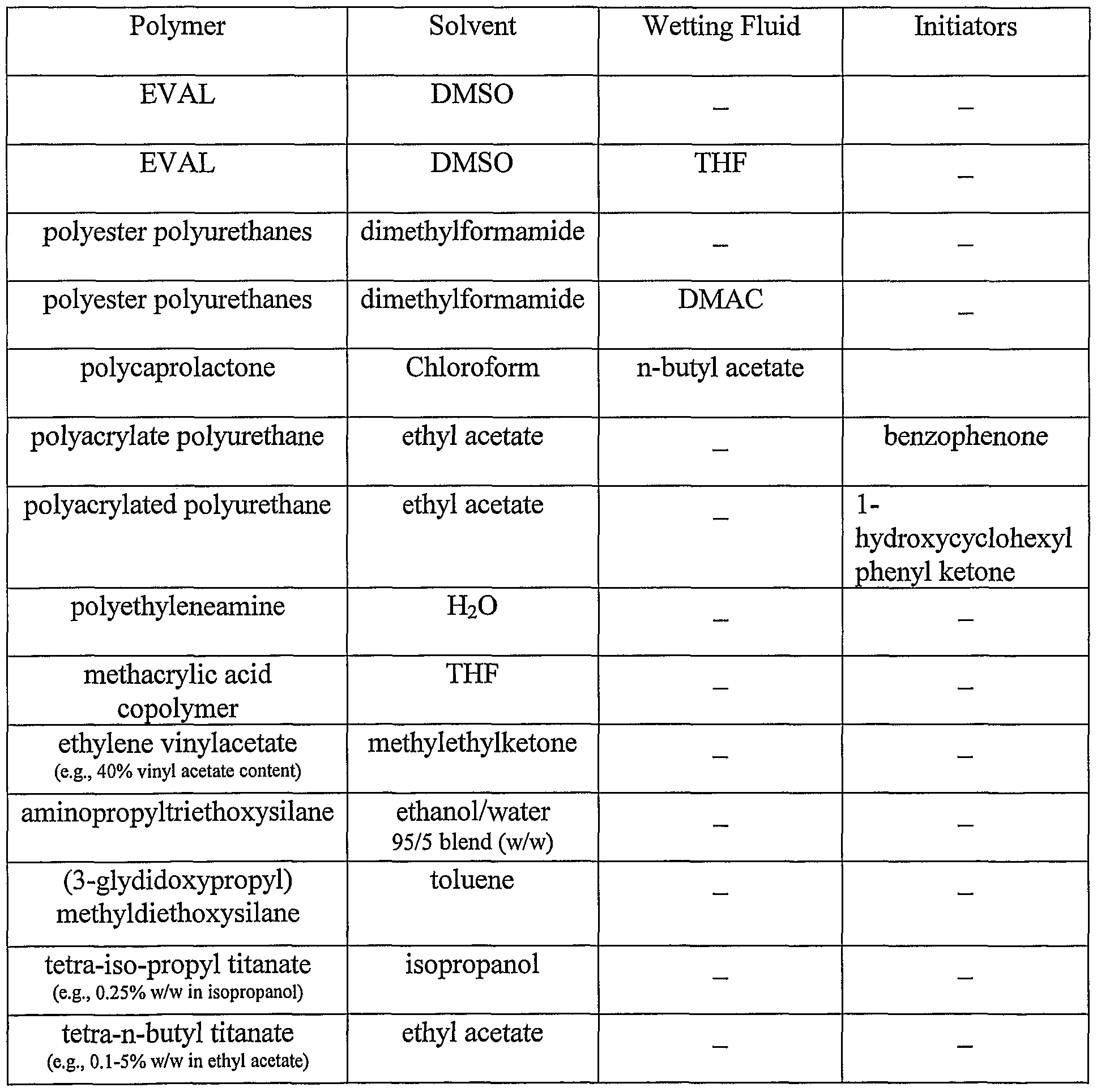
By way of example, and not limitation, the polymer can comprise from about 0.1% to about 35%, more narrowly about 2% to about 20% by weight of the total weight of the composition, and the solvent can comprise from about 65% to about 99.9%, more narrowly about 80%) to about 98% by weight of the total weight of the composition. A specific weight ratio is dependent on factors such as the material from which the implantable device is made and the geometrical structure of the device.
A fluid can also be added to the composition to enhance the wetting of the composition for a more uniform coating application. To enhance the wetting of the composition, a suitable fluid typically has a high capillary permeation. Capillary permeation or wetting is the movement of a fluid on a solid substrate driven by interfacial energetics. Capillary permeation is quantitated by a contact angle, defined as an angle at the tangent of a droplet in a fluid phase that has taken an equilibrium shape on a solid surface. A low contact angle means a higher wetting liquid. A suitably high capillary permeation corresponds to a contact angle less than about 90°.
Figure 3 A illustrates a fluid droplet 10A on a solid substrate 12, for example a stainless steel
surface. Fluid droplet 10A has a high capillary permeation that corresponds to a contact angle
Φi, which is less than about 90°. In contrast, Figure 3B illustrates a fluid droplet 10B on solid
substrate 12, having a low capillary permeation that corresponds to a contact angle Φ2, which is
greater than about 90°. The wetting fluid, typically, should have a viscosity not greater than
about 50 centipoise at room temperature, narrowly about 0.3 to about 5 centipoise, more
narrowly about 0.4 to about 2.5 centipoise. The wetting fluid, accordingly, when added to the
composition, reduces the viscosity of composition.
The wetting fluid should be mutually compatible with the polymer and the solvent and
should not precipitate the polymer. The wetting fluid can also act as the solvent. Useful
examples of the wetting fluid include, but are not limited to, tetraliydrofuran (THF),
dimethylformamide (DMF), 1-butanol, n-butyl acetate, dimethyl acetamide (DMAC), and
mixtures and combinations thereof. By way of example and not limitation, the polymer can
comprise from about 0.1% to about 35%, more narrowly from about 2% to about 20%) by weight
of the total weight of the composition; the solvent can comprise from about 19.9% to about
98.9%), more narrowly from about 58% to about 84% by weight of the total weight of the
composition; the wetting fluid can comprise from about 1% to about 80%, more narrowly from
about 5% to about 40% by weight of the total weight of the composition. The specific weight
ratio of the wetting fluid depends on the type of wetting fluid employed and type of and the
weight ratio of the polymer and the solvent. More particularly, tefrahydrofuran used as the
wetting fluid can comprise, for example, from about 1% to about 44%, more narrowly about
21% by weight of the total weight of the solution. Dimethylformamide used as the wetting fluid
can comprise, for example, from about 1% to about 80%, more narrowly about 8% by weight of the total weight of the solution. 1-butanol used as the wetting fluid can comprise, for example, from about 1% to about 33%, more narrowly about 9% by weight of the total weight of the solution. N-butyl acetate used as the wetting fluid can comprise, for example, from about 1% to about 34%o, more narrowly about 14% by weight of the total weight of the solution. Dimethyl acetamide used as the wetting fluid can comprise, for example, from about 1% to about 40%, more narrowly about 20% by weight of the total weight of the solution.
Table 1 illustrates some examples of suitable combinations for the primer composition:
Table 1
Figure imgf000019_0001
Composition for The Active Ingredient Layer
The embodiments of the composition for an active ingredient-containing or reservoir
layer are prepared by conventional methods wherein all components are combined, then blended.
More particularly, a predetermined amount of a polymeric compound is added to a
predetermined amount of a mutually compatible solvent or combination of solvents. The
polymeric compound can be added at ambient pressure and under anhydrous atmosphere. If
necessary, gentle heating and stirring and or mixing can be employed to effect dissolution of the
polymer into the solvent, for example 12 hours in a water bath at about 60°C.
The polymer chosen must be a polymer that is biocompatible and minimizes irritation to
the vessel wall when the device is implanted. The polymer may be either a biostable or a
bioabsorbable polymer. Bioabsorbable polymers that could be used include
poly(hydroxyvalerate), poly(L-lactic acid), polycaprolactone, poly(lactide-co-glycolide),
poly(hydroxybutyrate), poly(hydroxybutyrate-co-valerate), polydioxanone, polyorthoesters,
polyanl ydrides, poly(glycolic acid), poly(D,L-lactic acid), poly(glycolic acid-co-trimethylene
carbonate), polyphosphoesters, polyphosphoester urethanes, poly(amino acids), cyanoacrylates,
poly(trimethylene carbonate), poly(iminocarbonate), copoly(ether-esters) (e.g., PEO/PLA),
polyalkylene oxalates, polyphosphazenes and biomolecules such as fibrin, fibrinogen, cellulose,
starch, collagen and hyaluronic acid. Also, biostable polymers with a relatively low chronic
tissue response such as polyurethanes, silicones, and polyesters could be used and other
polymers could also be used if they can be dissolved and cured or polymerized on the stent such
as polyolefins, polyisobutylene and ethylene-alphaolefin copolymers; acrylic polymers and
copolymers, vinyl halide polymers and copolymers, such as polyvinyl chloride; polyvinyl ethers,
such as polyvinyl methyl ether; polyvinylidene halides, such as polyvinylidene fluoride and
polyvinylidene chloride; polyacrylonitrile; polyvinyl ketones; polyvinyl aromatics, such as polystyrene; polyvinyl esters, such as polyvinyl acetate; copolymers of vinyl monomers with
each other and olefins, such as ethylene-methyl methacrylate copolymers, acrylonitrile-styrene
copolymers, ABS resins, and ethylene-vinyl acetate copolymers; polyamides, such as Nylon 66
and polycaprolactam; alkyd resins; polycarbonates; polyoxymethylenes; polyimides; polyethers;
epoxy resins; rayon; rayon-triacetate; cellulose, cellulose acetate, cellulose butyrate; cellulose
acetate butyrate; cellophane; cellulose nitrate; cellulose propionate; cellulose ethers; and
carboxymethyl cellulose.
Ethylene vinyl alcohol is functionally a very suitable choice of polymer. The copolymer
allows for good control capabilities over the release rate of the active ingredient. As a general
rule, an increase in the amount of the ethylene comonomer content decreases the rate that the
active ingredient is released from the copolymer matrix. The release rate of the active ingredient
typically decreases as the hydrophilicity of the copolymer decreases. An increase in the amount
of the ethylene comonomer content increases the overall hydrophobicity of the copolymer,
especially as the content of vinyl alcohol is concomitantly reduced. It is also known that the
release rate and the cumulative amount of the active ingredient that is released is directly
proportional to the total initial content of the ingredient in the copolymer matrix. Accordingly, a
wide spectrum of release rates can be achieved by modifying the ethylene comonomer content
and the initial amount of the active ingredient.
The choice of polymer for the reservoir layer can be the same as or different from the
selected polymer for the primer layer. The use of the same polymer significantly reduces or
eliminates any interfacial incompatibilities, such as lack of an adhesive tie or bond, which may
exist with the employment of two different polymeric layers.
The solvent should be capable of placing the polymer into solution at the concentration
desired in the solution. Examples of solvent can include, but are not limited to, DMSO, chloroform, water (buffered saline), xylene, acetone, methanol, ethanol, 1-propanol, tetrahydrofuran, 1-butanone, dimethylformamide, dimethylacetamide, cyclohexanone, andN- methyl pyrrolidinone. With the use of low ethylene content, e.g., 29 mol%, ethylene vinyl alcohol copolymer, a suitable choice of solvent is iso-propylalcohol (IP A) admixed with water. Sufficient amounts of an active ingredient are dispersed in the blended composition of the polymer and the solvent. The active ingredient should be in true solution or saturated in the
blended composition. If the active ingredient is not completely soluble in the composition, operations including mixing, stirring, and/or agitation can be employed to effect homogeneity of the residues. The active ingredient may be added so that the dispersion is in fine particles. The mixing of the active ingredient can be conducted in an anhydrous atmosphere, at ambient pressure, and at room temperature such that supersaturating the active ingredient is not desired. The active ingredient should inhibit the activity of vascular smooth muscle cells. More specifically, the active ingredient is aimed at inhibiting abnormal or inappropriate migration and/or proliferation of smooth muscle cells. "Smooth muscle cells" include those cells derived from the medial and adventitial layers of the vessel which proliferate in intimal hyperplastic vascular sites following vascular trauma or
injury. Under light microscopic examination, characteristics of smooth muscle cells include a histological morphology of a spindle shape with an oblong nucleus located centrally in the cell with nucleoli present and myofibrils in the sarcoplasm. Under electron microscopic examination, smooth muscle cells have long slender mitochondria in the juxtanuclear sarcoplasm, a few tubular elements of granular endoplasmic reticulum, and numerous clusters of free ribosomes. A small Golgi complex may also be located near one pole of the nucleus.
"Migration" of smooth muscle cells means movement of these cells in vivo from the medial layers of a vessel into the intima, such as may also be studied in vitro by following the motion of a cell from one location to another, e.g., using time-lapse cinematography or a video
recorder and manual counting of smooth muscle cell migration out of a defined area in the tissue
culture over time.
"Proliferation" of smooth muscle cells means increase in cell number.
"Abnormal" or "inappropriate" proliferation means division, growth or migration of cells
occurring more rapidly or to a significantly greater extent than typically occurs in a normally
functioning cell of the same type, i.e., hyper-proliferation.
"Inhibiting" cellular activity means reducing, delaying or eliminating smooth muscle cell
hyperplasia, restenosis, and vascular occlusions, particularly following biologically or
mechanically mediated vascular injury or trauma or under conditions that would predispose a
mammal to suffer such a vascular injury or trauma. As used herein, the term "reducing" means
decreasing the intimal thickening that results from stimulation of smooth muscle cell
proliferation. "Delaying" means retarding the progression of the hyper-proliferative vascular
disease or delaying the time until onset of visible intimal hyperplasia, as observed, for example,
by histological or angiographic examination. "Elimination" of restenosis following vascular
trauma or injury means completely "reducing" and/or completely "delaying" intimal hyperplasia
in a patient to an extent which makes it no longer necessary to surgically intervene, i.e., to re¬
establish a suitable blood flow through the vessel by, for example, repeat angioplasty,
atherectomy, or coronary artery bypass surgery. The effects of reducing, delaying, or eliminating
restenosis may be determined by methods known to one of ordinary skill in the art, including,
but not limited to, angiography, intravascular ultrasound, fluoroscopic imaging, fiber optic
visualization, optical coherence tomography, intravascular MRI, or biopsy and histology.
Biologically mediated vascular injury includes, but is not limited to, injury caused by or
attributed to autoimmune disorders, alloimmune related disorders, infectious disorders including endotoxins and herpes viruses such as cytomegalovirus, metabolic disorders such as
atherosclerosis, and vascular injury resulting from hypothermia and irradiation. Mechanically mediated vascular injury includes, but is not limited to, vascular injury caused by catheterization procedures or vascular scraping procedures such as percutaneous transluminal coronary angioplasty, vascular surgery, stent placement, transplantation surgery, laser treatment, and other
invasive procedures which disrupted the integrity of the vascular intima or endothelium. The active ingredient of the invention is not restricted in use for therapy following vascular injury or trauma; rather, the usefulness of the active ingredient will also be determined by the ingredient's ability to inhibit cellular activity of smooth muscle cells or inhibit the development of restenosis. The active ingredient also includes any substance capable of exerting a therapeutic or
prophylactic effect in the practice of the present invention as well as having positive pharmacological effects on the expression of the extracellular matrix. The active ingredient can also be for enhancing wound healing in a vascular site and improving the structural and elastic properties of the vascular site. Examples of such active ingredients include antiproliferative substances as well as antineoplastic, antiinflammatory, antiplatelet, anticoagulant, antifibrin,
antithrombin, antimitotic, antibiotic, antioxidant, and combinations thereof. A suitable example of an antiproliferative substance includes actinomycin D, or derivatives and analogs thereof (manufactured by Sigma-Aldrich 1001 West Saint Paul Avenue, Milwaukee, WI 53233; or COSMEGEN available from Merck). Synonyms of actinomycin D include dactinomycin, actinomycin IV, actinomycin L, actinomycin Xi, and actinomycin Ci. Examples of suitable antineoplastics include paclitaxel and docetaxel. Examples of suitable antiplatelets, anticoagulants, antifibrins, and antithrombins include heparin, sodium heparin, low molecular weight heparin, heparin sulfate, heparin having a hydrophobic counterion, hirudin, argatroban, forskolin, vapiprost, prostacyclin and prostacyclin analogs, dextran, D-phe-pro-arg- chloromethylketone (synthetic antithrombin), dipyridamole, glycoprotein Ilb/Tlla platelet membrane receptor antagonist, recombinant hirudin, thrombin inhibitor (available from Biogen), and 7E-3B® (an antiplatelet drug from Centocore). Examples of suitable antimitotic agents include methotrexate, azathioprine, vincristine, vinblastine, fluorouracil, adriamycin, and mutamycin. Examples of suitable cytostatic or antiproliferative agents include angiopeptin (a somatostatin analog from Ibsen), angiotensin converting enzyme inhibitors such as CAPTOPRIL (available from Squibb), CILAZAPRIL (available from Hoffman-LaRoche), or LISINOPRIL (available from Merck); calcium channel blockers (such as Nifedipine), colchicine, fibroblast growth factor (FGF) antagonists, fish oil (omega 3 -fatty acid), histamine antagonist, LOVASTATIN (an inhibitor of HMG-CoA reductase, a cholesterol lowering drug from Merck), monoclonal antibodies (such as PDGF receptors), nitroprusside, phosphodiesterase inhibitors, prostaglandin inhibitor (available form Glazo), Seramin (a PDGF antagonist), serotonin blockers, steroids, thioprotease inhibitors, triazolopyrimidine (a PDGF antagonist), and nitric oxide. Other therapeutic substances or agents which may be appropriate include mannose-6- phosphate, superoxide dismutase, retinoic acid, suramin, asiaticoside, hyaluronan, alpha- interferon, genetically engineered epithelial cells, dexamethasone and rapamycin and structural derivatives or functional analogs thereof, such as 40-O-(2-hydroxy)ethyl-rapamycin (known by the trade name of EVEROLIMUS available from Novartis), 40-O-(3-hydroxy)propyl-rapamycin, 40-O-[2-(2-hydroxy)ethoxy]ethyl-rapamycin, and 40-O-tetrazole-rapamycin. Exposure of the composition to the active ingredient is not permitted to adversely alter the active ingredient's composition or characteristic. Accordingly, the particular active ingredient is selected for mutual
compatibility with the blended composition.
The dosage or concentration of the active ingredient required to produce a favorable therapeutic effect should be less than the level at which the active ingredient produces toxic effects and greater than the level at which non-therapeutic results are obtained. The dosage or concentration of the active ingredient required to inhibit the desired cellular activity of the vascular region can depend upon factors such as the particular circumstances of the patient; the nature of the trauma; the nature of the therapy desired; the time over which the ingredient administered resides at the vascular site; and if other bioactive substances are employed, the nature and type of the substance or combination of substances. Therapeutic effective dosages can be determined empirically, for example by infusing vessels from suitable animal model systems and using immunohistochemical, fluorescent or electron microscopy methods to detect the agent and its effects, or by conducting suitable in vitro studies. Standard pharmacological test procedures to determine dosages are understood by one of ordinary skill in the art.
By way of example, the polymer can comprise from about 0.1% to about 35%, more narrowly from about 2% to about 20% by weight of the total weight of the composition, the solvent can comprise from about 59.9% to about 99.8%, more narrowly from about 79% to about 87% by weight of the total weight of the composition, and the active ingredient can
comprise from about 0.1% to about 75%, more narrowly from about 20%> to about 60%) by weight of the total weight of the composition. Selection of a specific weight ratio of the polymer and solvent is dependent on factors such as, but not limited to, the material from which the device is made, the geometrical structure of the device, and the type and amount of the active ingredient employed. The particular weight percentage of the active ingredient mixed within the composition depends on factors such as duration of the release, cumulative amount of release, and release rate that is desired.
Optionally, a second fluid or solvent, such as tetrahydrofuran (THF) or dimethylformamide (DMF) can be used to improve the solubility of an active ingredient in the composition and/or to increase the wetting of the composition. Increasing the wetting of the composition has been discovered to lead to the application of a more uniformed coating. The second fluid or solvent can be added to the composition or the active ingredient can be added to
the second solvent prior to admixture with the blend.
With use of a second fluid, by way of example, the polymer can comprise from about 0.1% to about 35%, more narrowly from about 2% to about 20% by weight of the total weight of the composition, the solvent can comprise from about 19.8% to about 98.8%, more narrowly from about 49% to about 79% by weight of the total weight of the composition, the second solvent can comprise from about 1% to about 80%>, more narrowly from about 5% to about 40% by weight of the total weight of the composition, and the active ingredient can comprise from about 0.1 % to about 40%, more narrowly from about 1 % to about 9% by weight of the total weight of the composition. Selection of a specific weight ratio of the polymer, the solvent, and
the second solvent is dependent on factors such as, but not limited to, the material from which the implantable device is made, the geometrical structure of the device, and the type and amount of the active ingredient employed. The particular weight percentage of the active ingredient mixed within the composition depends on factors such as duration of the release, cumulative
amount of release, and release rate that is desired.
Table 2 is an exemplary list of suitable combinations:
Table 2
Figure imgf000028_0001
Composition for The Rate Reducing Membrane The embodiments of the composition for a rate-reducing membrane or diffusion barrier layer are prepared by conventional methods wherein all components are combined. In the embodiment with the use of particles, dispersion techniques should also be employed to circumvent agglomeration or formation of particle floes.
More particularly, the composition for the barrier layer can be applied on a selected portion of the reservoir layer. The barrier layer can reduce the rate of release or delay the time at which the active ingredient is released from the reservoir region. In one embodiment, for maximum blood compatibility, polyethylene glycol or polyethylene oxide can also be added to the blend. Ethylene vinyl alcohol is functionally a very suitable choice of polymer. The copolymer allows for good control capabilities over the release rate of the active ingredient. As a general rule, an increase in the amount of the ethylene comonomer content decreases the rate that the active ingredient is released from the copolymer matrix. The release rate of the active ingredient decreases as the hydrophilicity of the polymer decreases. An increase in the amount of the ethylene comonomer content increases the overall hydrophobicity of the copolymer, especially as the content of vinyl alcohol is concomitantly reduced. Usefully, the choice of polymer for the barrier layer can be the same as the selected
polymer for the reservoir. The use of the same polymer can significantly reduce or eliminate interfacial incompatibilities, such as lack of adhesion, which may exist in the employment of two different polymeric layers.
Particles of inorganic or organic type can be added to the blend. The particles can be made from any suitable material having barrier-type properties, such as, but not limited to tortuousity, excluded volume, and adsorptivity. "Tortuosity" refers to the exclusion of space in the polymer matrix for the creation of a defined space or a tortuous path through and about which the active ingredient must travel to be expelled from the layer. "Excluded volume" refers to the volume displaced by the particles that would otherwise be available for the diffusion of the active ingredient. "Adsorptivity" refers to the chromatographic effect which is dependent upon
the interaction between the active ingredient used in combination with the particle. The active ingredient may be partially adsorbed and released by the surface of the particles, such as silica or fumed carbon particles.
The particles should be dispersed in the blend. "Dispersed" is defined as the particles
being present as individual particles, not agglomerates or floes. In certain polymer-solvent blends, certain particles will disperse with ordinary mixing. Otherwise the particles can be dispersed in the composition by high shear processes such as ball mill, disc mill, sand mill, attritor, rotor stator mixer, ultrasonication ~ all such high shear dispersion techniques being well known to one of ordinary skill in the art. Optionally, one of the aforementioned wetting fluids can also be added to the blend. The wetting fluid can be added prior to, contemporaneously with, or subsequent to the agitation. Biocompatible dispersing agents in the form of surfactants, emulsifiers, or stabilizers may also be added to the blend to assist in particle dispersion.
The particles can be made from a metal oxide, such as rutile titanium oxide, anatase titanium dioxide, niobium oxide, tantalum oxide, zirconium oxide, iridium oxide, or tungsten oxide. In another embodiment, the particles can be made from a main group oxide such as silica (silicon oxide) or alumina (aluminum oxide). Metallic particles such as gold, hafnium, platinum,
iridium, palladium, tungsten, tantalum, niobium, zirconium, titanium, aluminum, or chromium can also be employed. In another embodiment, carbonaceous particles made from, for example, lamp black, furnace black, carbon black, fumed carbon black, gas black, channel black, activated charcoal, diamond, diamond like carbon, or CVD diamond can be employed. In yet another embodiment, the particles can be made from nitrides such as titanium nitride, chromium nitride, and zirconium nitride. In yet another embodiment, carbides such as tungsten carbide, silicon carbide, or titanium carbide, and calcium salts such as hydroxyapatite, dahlite, brushite, tricalcium phosphate, calcium sulphate, and calcium carbonate can be used. Other inorganic particles can include particles made from suicides, barium titanate, and strontium titanate.
The particles can also be made from a suitable polymer including polymers of
polyolefins, polyurethanes, cellulosics (i.e., polymers having mer units derived from cellulose), polyesters, polyamides, poly(hexamethylene isophthalamide/terephthalamide) (commercially available as SELAR PA™), polyethylene terephthalate-co-p-oxybenzoate) (PET/PHB, e.g., copolymer having about 60-80 mole percent PHB), poly(hydroxy amide ethers), polyacrylates, polyacrylonitrile, acrylonitrile/styrene copolymer (commercially available as LOP AC), rubber- modified acrylonitrile/acrylate copolymer (commercially available as BAREX), poly(methyl methacrylate), liquid crystal polymers (LCP) (e.g., VECTRA available from Hoescht-Celanese, ZENITE available from DuPont, and XYDAR available from Amoco Performance Chemicals),
poly(phenylene sulfide), polystyrenes, polycarbonates, poly(vinyl alcohols), poly(ethylene-vinyl
alcohol) (EVAL, e.g., having about 27 to about 47 mole percent of ethylene content), epoxies
composed of bisphenol A based diepoxides with amine cure, aliphatic polyketones (e.g.,
CARILON available from Shell, and KETONEX available from British Petroleum),
polysulfones, poly(ester-sulfone), poly(urethane-sulfone), poly(carbonate-sulfone), poly(3-
hydroxyoxetane), poly(amino ethers), gelatin, amylose, parylene-C, parylene-D, parylene-N.
Representatives polyolefins include those based upon alpha-monoolefin monomers
having from about 2 to 6 carbon atoms and halogen substituted olefins, i.e., halogenated
polyolefins. By way of example, and not limitation, low to high density polyethylenes,
essentially unplasticized poly (vinyl chloride), poly (vinylidene chloride), poly (vinyl fluoride),
poly (vinylidene fluoride), poly (tetrafluoroethylene) (Teflon), poly (chlorotrifluoroethylene)
(KEL-F), and mixtures thereof are suitable. Low to high density polyethylenes are generally
understood to have densities of about 0.92 g cm"3 to about 0.96 g cm"3, however, no bright line
can be drawn for density classifications and the density can vary according to the supplier.
Representative polyurethanes include polyurethanes having a glass transition temperature
above a storage or ambient temperature, for example having a glass transition temperature of at
least 40°C to 60°C, or having a non-polar soft segment which includes a hydrocarbon, silicone,
fluorosilicone, or mixtures thereof. For example, ELAST-EON, manufactured by
Elastomedic/CSIRO Molecular Science, is a polyurethane with a non-polar soft segment which
is made from 1,4-butanediol, 4,4'-methylenediphenyl diisocyanate, and a soft segment composed
of a blend poly(hexamethylene oxide) (PHMO) and
bishydroxyethoxypropylpolydimethylsiloxane (PDMS). A useful example has a blend of 20%
by weight PHMO and 80% by weight PDMS. Representative examples of cellulosics include, but are not limited to, cellulose acetate having a degree of substitution (DS) greater than about 0.8 or less than about 0.6, ethyl cellulose, cellulose nitrate, cellulose acetate butyrate, methyl cellulose, and mixtures thereof.
Representative polyesters include saturated or unsaturated polyesters such as, but not limited to, poly (butylene terephthalate), poly(ethylene 2,6-naphthalene dicarboxylate) (PEN), and poly (ethylene terephthalate).
Representative polyamides include crystalline or amorphous polyamides such as, but not limited to, nylon-6, nylon-6,6, nylon-6,9, nylon-6,10, aromatic nylon MXD6 (manufactured by Mitsubishi Gas Chemical America, Inc.), and mixtures thereof. Representative polyacrylates include, but are not limited to, poly(methylmethacrylate) and polymethacrylate.
The particle can be a mixture of the aforementioned polymers. For example, the polymer can comprise about 70% to about 99% by weight acrylonitrile and about 30% to about 1% by weight styrene. Similarly, copolymers of vinyl chloride and vinylidene chloride with a vinyl chloride content of about 1 to about 30 mole percent and PET/PHB copolymers with a PHB
content of about 60 to about 80 mole percent function effectively.
Methods For Applying the Compositions to the Device Before applying the primer layer, the surface of the device or prosthesis should be clean and free from contaminants that may be introduced during manufacturing. However, the surface of the prosthesis requires no particular surface treatment to retain the applied coating. Metallic
surfaces of stents can be, for example, cleaned by argon plasma process as is well known to one of ordinary skill in the art. Application of the composition can be by any conventional method, such as by spraying the composition onto the prosthesis or immersing the prosthesis in the composition. Operations such as wiping, centrifugation, blowing, or other web clearing acts can also be performed to achieve a more uniform coating. Briefly, wiping refers to physical removal
of excess coating from the surface of the stent; centrifugation refers to rapid rotation of the stent
about an axis of rotation; and blowing refers to application of air at a selected pressure to the
deposited coating. The excess coating can also be vacuumed off the surface of the device. The
addition of a wetting fluid leads to a consistent application of the composition, which also causes
the coating to be uniformly deposited on the surface of the prosthesis.
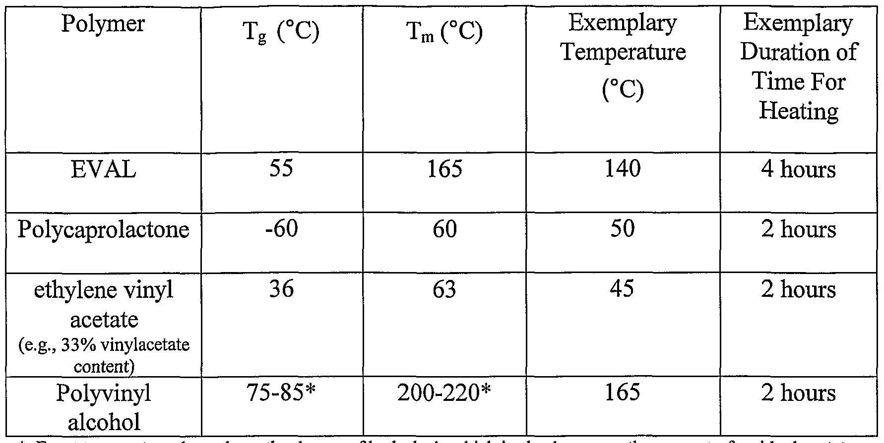
With the use of the thermoplastic polymers, such as EVAL, polycaprolactone,
poly(lactide-co-glycolide), poly(hydroxybutyrate), etc., the deposited primer composition can be
exposed to a heat treatment at a temperature range greater than about the glass transition
temperature (Tg) and less than about the melting temperature (Tm) of the selected polymer.
Unexpected results have been discovered with treatment of the composition under this temperature range, specifically strong adhesion or bonding of the coating to the metallic surface
of a stent. The device should be exposed to the heat treatment for any suitable duration of time,
which would allow for the formation of the primer coating on the surface of the device and
allows for the evaporation of the solvent or combination of solvent and wetting fluid. It is
understood that essentially all of the solvent and the wetting fluid will be removed from the
composition but traces or residues can remain blended with the polymer.
Table 3 lists the Tg and Tm for some of the polymers used in the embodiments of the
present invention. Tg and Tm of polymers are attainable by one of ordinary skill in the art. The
cited exemplary temperature and time for exposure is provided by way of illustration and it is not
meant to be limiting. Table 3
Figure imgf000034_0001
* Exact temperature depends on the degree of hydrolysis which is also known as the amount of residual acetate.
With the use of one of the aforementioned thermoset polymers, the use of initiators may be required. By way of example, epoxy systems consisting of diglycidyl ether of bisphenol A resins can be cured with amine curatives, thermoset polyurethane prepolymers can be cured with polyols, polyamines, or water (moisture), and acrylated urethane can be cured with UV light. If
baked, the temperature can be above the Tg of the selected polymer.
With the use of the inorganic polymers, such as silanes, titanates, and zirconates the composition containing the prepolymer or precursor is applied and the solvent is allowed to evaporate.
As the primer layer is being applied or after the primer coating has been formed, the
surface of the primer can be modified in order to increase the surface area of the primer. For instance, in one embodiment, asperities, or areas of roughness, are created on the surface of the primer layer. A variety of methods can be used to create the asperities on the primer layer covering the outer surface of the prosthesis. In one method, a pressurized stream of grit material is directed upon the polymeric primer coating after the primer layer has been dried. Examples of such processes include bead blasting and sand blasting. Bead blasting refers to the use of pressurized gas to project beads of a relatively uniform diameter at an object at a high velocity. The beads may be made of materials such as, but not limited to, aluminum oxide, silicon oxide, or latex. In sand blasting, the grit projected does not have as uniform diameter as in bead blasting. Both bead blasting and sand blasting are techniques that are well known to those of ordinary skill in the art. The roughness achieved using a pressurized grit source can be controlled by the size of the grit, e.g., the diameter of the beads, the pressure used, the distance between the grit source and the primer surface and the length of time the grit is blasted at the
primer surface. By way of example and not limitation, the grit can be beads having a diameter of between 10 μm and 50 μm. Pressures of 30 PSI (pounds per square inch) to 60 PSI can be used to project the beads from a distance of approximately 3 to 10 cm from the stent.
Laser etching can also be used to create asperities or pores on the primer coating after the primer layer has been dried. Laser lithographic methods are known to those of ordinary skill in the art. A laser is directed onto the primer coating for a predetermined period of time, which depends on the etch rate and the depth of etch desired. A patterned mask that has openings may be applied over the primer coating before the laser is utilized. The laser is then allowed to etch the primer through the openings of the mask. The use of patterned masks with laser etchings is
known to those of ordinary skill in the art.
In addition, the manner in which the primer is deposited onto the outer surface of the stent can create the asperities. The primer may be added via physical deposition processes, for example, by sputtering. Process conditions in which a lower pressure and shorter deposition time than is typically used for thin film deposition are used to form the asperities in the primer coating.
In addition, the surface of the primer coating can be modified by using a method to form a porous matrix. A porous matrix for the primer coating can be provided, for example, by phase inversion precipitation of a portion of the polymer in the primer layer. By way of example, a polymer is mixed with two miscible solvents to form a solution. One of the solvents (solvent A) should be less volatile than the other solvent (solvent B). Additionally, the polymer should be less soluble in solvent A. The solution can then be applied to a portion of the surface of the
implantable device. Next, when the solvents are allowed to evaporate, the polymer slowly precipitates as solvent B is essentially removed from the coating. As a result, after complete drying, the polymer matrix becomes porous. One of ordinary skill in the art will understand that the size of the pores can be controlled by the choice of polymers and solvents and the relative concentrations of the solutions. The depth of porous matrix into the primer region can be
controlled by only using the phase inversion technique after a portion of the primer layer has been applied to the surface of the stent. Pores in the range of about 0.1 microns to about 1 micron in diameter may be suitable.
The porous matrix in the primer layer can also be formed by using porogens. For example, a porogen can be added to the primer composition as monodispersed particles to create
a porogen suspension. The porogen particles can comprise from about 5% to about 50% by weight of the total weight of the primer composition. The size of the porogen particles can be about 0.1 microns to 2 microns. The composition can then be applied to the device and after the layer is formed, the porogens can be dissolved away with an appropriate solvent, leaving cavities
or pores in the primer layer to form the porous matrix. Representative examples of porogen particles include sodium chloride and glycine spheres. Usefully, the appropriate solvent is a compatible solvent for the porogen, but does not substantially dissolve the polymer used to form the primer layer. Water is a representative example of an appropriate solvent if sodium chloride or glycine spheres are used as the porogen. The porous matrix can also be formed by using a sintering process. Sintering is a process of fabrication where particles are bonded together by partially melting some of the particles. For example, a polymeric powder or particles can be applied to the surface of the device and then pressed together. The particles can usefully be about 1 micron to about 10 microns. Then, the polymeric particles can be heated to temperatures slightly below or about the melting point of the polymer. Without entirely melting all of the particles, the particles bond to each other at their respective surfaces. Space remains between the lattice of the particles to form porous
cavities.
Subsequent to the application of the primer layer, the composition containing the active ingredient (i.e., reservoir layer) can be applied to a designated portion of the primer coating. Masking techniques can be implemented for applying compositions containing different active
ingredients to selected portions of the primer layer. Accordingly, stents having various cocktail formulations or combinations of a variety of active ingredients can be manufactured. The solvent(s) or the combination of the solvent(s) and the wetting fluid is removed from the composition by allowing the solvent(s) or combination of the solvent(s) and the wetting fluid to
evaporate. The evaporation can be induced by heating the device at a predetermined temperature for a predetermined period of time. For example, the device can be heated at a temperature of about 60°C for about 12 hours to about 24 hours. The heating can be conducted in an anhydrous atmosphere and at ambient pressure and should not exceed the temperature which would adversely affect the active ingredient. The heating can, alternatively, be conducted under a vacuum condition. It is understood that essentially all of the solvent and the wetting fluid will be removed from the composition containing the active ingredient but traces or residues can remain blended with the polymer. A diffusion barrier layer can also be applied on a designated portion of the active
ingredient-containing coating subsequent to the evaporation of the solvent(s) or
solvent(s)/wetting fluid and the drying of the polymer for the active ingredient-containing
coating. The diffusion barrier layer can also be applied by spraying the composition onto the
device or immersing the device in the composition. The above-described processes can be
similarly repeated for the formation of the barrier region.
Method of Use
In accordance with the above-described method, the active ingredient can be applied to a
medical device, e.g., a stent, retained on the stent during delivery and expansion of the stent, and
released at a desired control rate and for a predetermined duration of time at the site of
implantation. A stent having the above-described coating layers is useful for a variety of
medical procedures, including, by way of example, treatment of obstructions caused by tumors
in bile ducts, esophagus, trachea/bronchi and other biological passageways. A stent having the
above-described coating layers is particularly usef l for treating occluded regions of blood
vessels caused abnormal or inappropriate migration and proliferation of smooth muscle cells,
thrombosis, and restenosis. Stents may be placed in a wide array of blood vessels, both arteries
and veins. Representative examples of sites include the iliac, renal, and coronary arteries. The
application of the present invention should not, however, be limited to stents such that the
embodiments of the coating can be used with a variety of medical substrates.
Briefly, an angiogram is first performed to determine the appropriate positioning for stent
therapy. Angiography is typically accomplished by injecting a radiopaque contrast agent through
a catheter inserted into an artery or vein as an x-ray is taken. A guidewire is then advanced
through the lesion or proposed site of treatment. Over the guidewire is passed a delivery catheter
which allows a stent in its collapsed configuration to be inserted into the passageway. The delivery catheter is inserted either percutaneously or by surgery into the femoral artery, brachial
artery, femoral vein, or brachial vein, and advanced into the appropriate blood vessel by steering
the catheter through the vascular system under fluoroscopic guidance. A stent having the above described coating regions may then be expanded at the desired area of treatment. A post
insertion angiogram may also be utilized to confirm appropriate positioning.
EXAMPLES
The embodiments of the invention will be illustrated by the following set forth examples
which are being given by way of illustration only and not by way of limitation. All parameters
and data are not be construed to unduly limit the scope of the embodiments of the invention.
Example 1
Multi-Link™ stents (available from Guidant Corporation) were cleaned by placement in
an ultrasonic bath of isopropyl alcohol solution for 10 minutes. The stents were dried and
plasma cleaned in a plasma chamber. An EVAL solution was made with 1 gram of EVAL and 7
grams of DMSO, making an EVAL:DMSO ratio of 1 :7. The mixture was placed in a warm
water shaker bath at 60°C for 24 hours. The solution was cooled and vortexed. The cleaned
Multi-Link™ stents were dipped in the EVAL solution and then passed over a hot plate, for
about 3-5 seconds, with a temperature setting of about 60°C. The coated stents were heated for 6
hours in an air box and then placed in an oven at 60°C, under vacuum condition, and for 24
hours. The coated stents were expanded on a 4.0 mm angioplasty balloon. The coatings
remained intact on the stents. The coatings were transparent giving the Multi-Link™ stents a glossy-like shine. Example 2 Multi-Link™ stents were cleaned by placement in an ultrasonic bath of isopropyl alcohol solution for 10 minutes. The stents were dried and plasma cleaned in a plasma chamber. An EVAL solution was made with 1 gram of EVAL and 4 grams of DMSO, making an EVAL:DMSO ratio of 1 :4. Dexamethasone was added to the 1 :4 EVAL:DMSO solution.
Dexamethasone constituted 9% by weight of the total weight of the solution. The solution was vortexed and placed in a tube. The cleaned Multi-Link™ stents were attached to mandrel wires and dipped into the solution. The coated stents were passed over a hot plate, for about 3-5 seconds, with a temperature setting of about 60°C. The coated stents were cured for 6 hours in an air box and then placed in a vacuum oven at 60°C for 24 hours. The above-recited step was repeated twice. The average weight of the coating was 0.0003 gram, having an estimated dexamethasone content of 75 ug per stent. The coated stents were expanded on a 4.0 mm
angioplasty balloon. The coatings remained intact on the stents. Verification of coverage and physical properties of the coatings were visualized using a scanning electron microscope. The coatings were transparent, giving the Multi-Link™ stents a glossy-like shine.
Example 3 Multi-Link Duet™ stents are cleaned by placement in an ultrasonic bath of isopropyl
alcohol solution for 10 minutes. The stents are dried and plasma cleaned in a plasma chamber. The EVAL solution is made with 1 gram of EVAL and 4 grams of DMSO, making an EVAL:DMSO ratio of 1 :4. Dexamethasone is added to the 1 :4 EVAL:DMSO solution.
Dexamethasone constitutes 9% by weight of the total weight of the solution. The solution is vortexed and placed in a tube. The cleaned Multi-Link™ stents are attached to mandrel wires and dipped into the solution. The coated stents are passed over a hot plate, for about 3-5 seconds, with a temperature setting of about 60°C. The coated stents are cured for 6 hours in an air box then placed in a vacuum oven at 60°C for 24 hours. The single layered
dexamethasone/EVAL coated stents are dipped into the 1 :4 ratio EVAL:DMSO solution, free from dexamethasone. The stents are passed over the hot plate, cured, and placed in the oven as previously described. The top coating will provide a barrier layer for controlling the release of , dexamethasone from the drug coated layer. The coated stents can be expanded on a 4.0 mm
) angioplasty balloon. It is predicted that the coatings will remain intact on the stents. The coatings will be transparent, giving the Multi-Link™ stents a glossy-like shine.
Example 4 Multi-Link™ stents were cleaned by placement in an ultrasonic bath of isopropyl alcohol solution for 10 minutes. The stents were dried and plasma cleaned in a plasma chamber. An EVAL solution was made with 1 gram of EVAL and 7 grams of DMSO, making an EVAL:DMSO ratio of 1:7. Vinblastine was added to the 1:7 EVAL:DMSO solution. Vinblastine constituted 2.5% by weight of the total weight of the solution. The solution was vortexed and placed in a tube. The cleaned Multi-Link™ stents were attached to mandrel wires and dipped into the solution. The coated stents were passed over a hot plate, for about 3-5 seconds, with a temperature setting of about 60°C. The coated stents were cured for 6 hours in an air box then placed in a vacuum oven at 60°C for 24 hours. The above process was repeated twice, having a total of three layers. The average weight of the coating was 0.00005 gram, with an estimated vinblastine concentration of 12 microgram per stent. Some of the stents were
sterilized by electron beam radiation. The sterilized and unsterilized vinblastine coated stents were tested for a 24 hour elution period by placing one sterilized and one unsterilized stent in 5 ml of phosphated saline solution (pH 7.4) at room temperature with rotational motion. The amount of vinblastine eluted was evaluated by High Performance Liquid Chromatography (HPLC) analysis. The results of this test are given below and plotted in Figure 4. The data indicates that electron beam radiation procedure does not interfere in the release of vinblastine
Figure imgf000042_0001
Release Profile For Vinblastine — Unsterilized
Figure imgf000042_0002
Release Profile For Vinblastine — Sterilized
Figure imgf000042_0003
Example 5
Multi-Link™ stents were cleaned by placement in an ultrasonic bath of isopropyl alcohol
solution for 10 minutes. The stents were dried and plasma cleaned in a plasma chamber. An
EVAL solution was made with 1 gram of EVAL and 7 grams of DMSO, making an
EVAL:DMSO ratio of 1 :7. Cephalotaxin was added to the 1 :7 EVAL:DMSO solution.
Cephalotaxin constituted 5% by weight of the total weight of the solution. The solution was
vortexed and placed in a tube. The cleaned Multi-Link™ stents were attached to mandrel wires
and dipped into the solution. The coated stents were passed over a hot plate, for about 3-5
seconds, with a temperature setting of about 60°C. The coated stents were cured for 6 hours in
an air box then placed in a vacuum oven at 60°C for 24 hours. The above process was repeated
twice, having a total of three layers. The average weight of the coating was 0.00013 gram, with
an estimated cephalotaxin concentration of 33 ug. The stents were sterilized by electron beam
radiation. Cephalotaxin/EVAL coated stents and EVAL-coated control stents were implanted in
the coronary arteries of 4 pigs, generally in accordance to the procedure set forth in "Restenosis
After Balloon Angioplasty-A Practical Proliferative Model in Porcine Coronary Arteries" by
Robert S. Schwartz, et al, Circulation 82(6):2190-2200, Dec. 1990, and "Restenosis and the
Proportional Neointimal Response to Coronary Artery Injury: Results in a Porcine Model" by
Robert S. Schwartz et al, J Am Coll Cardiol; 19:267-74 Feb. 1992. Results of the porcine artery
study indicated that there was no significant difference between the uncoated, EVAL coated and
cephalotaxin coated stents in the amount of neointimal proliferation resulting from arterial
injury.
Example 6
Multi-Link Duet™ stents (available from Guidant Corporation) were cleaned by
placement in an ultrasonic bath of isopropyl alcohol solution for 20 minutes, then air dried. An EVAL stock solution was made with 1 gram of EVAL and 7 grams of DMSO, making an EVAL:DMSO ratio of 1 :7. The mixture was placed in a warm water shaker bath at 60°C for 12 hours. The solution was mixed, then cooled to room temperature. A co-solvent was added to
the EVAL solution to promote wetting of the struts of the Multi-Link Duet™ stents. One gram
of tetrahydrofuran (THF) was mixed with 1.2 grams of the EVAL:DMSO solution. The cleaned
Multi-Link Duet™ stents were attached to mandrel wires and dipped into the solution. The
coated stents were passed over a hot plate, for about 3 to 5 seconds, with a temperature setting of about 60°C. The coated stents were then heated in a laboratory oven at 90°C for 4 hours. The thin EVAL coating adhered to stainless steel without peeling or cracking. EVAL forms a superior primer base coat for other polymers that do not adhere well to stainless steel.
Example 7
Multi-Link Duet™ stents were cleaned in an ultrasonic bath of isopropyl alcohol for 20
minutes, then air dried. An EVAL solution was made with 1 gram of EVAL and 5 grams of DMSO, making an EVAL:DMSO ratio of 1 :5. The mixture was placed in a warm water shaker bath at 60°C for 12 hours. The solution was mixed, then cooled to room temperature. The dissolved EVAL:DMSO solution was mixed with 24.6 grams of THF and 19.56 grams of DMSO. The solution was mixed then placed in the reservoir of an air pressured atomizing
sprayer. Multi-Link Duet™ stents were sprayed while the stents rotated between 30 to 120 rpm.
The spray time was dependent upon the flow rate of the sprayer. A flow rate between 1 to 20 mg/second required a stent to be sprayed between 1 to 30 seconds. The polymer coated Multi-
Link Duet™ stents were heated in a forced air convection oven for 12 hours. The coatings were
transparent, giving the Multi-Link Duet™ stents a glossy-like shine. Example 8
Multi-Link Duet™ stents were cleaned in an ultrasonic bath of isopropyl alcohol for 20
minutes, then air dried. An EVAL stock solution was made having an EVAL:DMSO ratio of 1 :4. The mixture was placed in a warm water shaker bath at 60°C for 12 hours. The solution was mixed, then cooled to room temperature. Various co-solvents were examined to determine which co-solvent would promote a thicker coating. These co-solvents were THF, DMF, 1- butanol, and n-butyl acetate. The formulation for the co-solvents was as follows. Three grams of dissolved EVAL:DMSO solution was mixed with 0.9 gram of THF; three grams of dissolved EVAL:DMSO solution was mixed with 0.39 gram of DMF; three grams of dissolved EVAL:DMSO solution was mixed with 0.5 gram of 1 -butanol; and three grams of dissolved EVAL:DMSO solution was mixed with 0.68 gram of n-butyl acetate. The cleaned Multi-Link
Duet™ stents, attached to mandrel wires, were dipped into the solutions. The coated stents were
passed over a hot plate, for about 3 to 5 seconds, with a temperature setting of about 60°C. The coated stents were heated in a forced air convection oven for 24 hours. A second layer of
coating was applied to coated Multi-Link Duet™ stents and the stents were heated in the same
manner as above. No difference was seen between the stents coated with the various co-solvents (e.g., greater weight of coating or physical appearance). All coated stents were transparent,
giving the Multi-Link Duet™ stents a glossy-like shine. No webbing or bridging of the coating
was seen between the struts of the coated Multi-Link Duet™ stents. The weight of the coatings
was between 0.2 to 0.27 mg/stent.
Example 9
Multi-Link Duet™ stents are cleaned in an ultrasonic bath of isopropyl alcohol for 20
minutes, then air dried. An EVAL stock solution is made having an EVAL:DMSO ratio of 1 :4. The mixture is placed in a warm water shaker bath at 60°C for 12 hours. The solution is mixed, then cooled to room temperature. A 9% by weight Dexamethasone solution is formulated as follows: 2.96 grams of the EVAL:DMSO solution is mixed with 0.29 gram of Dexamethasone,
then 0.9 gram of THF is added. The cleaned Multi-Link Duet™ stents are attached to mandrel
wires and dipped into the solution. The coated stents are passed over a hot plate, for about 3 to 5 seconds, with a temperature setting of about 60°C. The coated stents are cured in a forced air convection oven for 2 hours. A second layer of coating is applied and cured in the above
manner. It is predicted that the coatings will be transparent, giving the Multi-Link Duet™ stents a glossy-like shine.
Example 10
Multi-Link Duet™ stents are cleaned in an ultrasonic bath of isopropyl alcohol for 20
minutes, then air dried. An EVAL stock solution is made having an EVAL:DMSO ratio of 1 :4. The mixture is placed in a warm water shaker bath at 60°C for 12 hours. The solution is mixed, then cooled to room temperature. A 9% by weight Dexamethasone solution is formulated as follows: 2.96 grams of the EVAL:DMSO solution is mixed with 0.29 gram of Dexamethasone,
then 0.9 gram of THF is added. The cleaned Multi-Link Duet™ stents are attached to mandrel
wires and dipped into the solution. The coated stents are passed over a hot plate, for about 3 to 5 seconds, with a temperature setting of about 60°C. The coated stents are cured in a forced air convection oven for 2 hours. A second layer of coating is applied and cured in the above
manner. It is predicted that the coatings will be transparent, giving the Multi-Link Duet™ stents
a glossy-like shine.
Example 11
Multi-Link Duet™ stents were cleaned in an ultrasonic bath of isopropyl alcohol for 20
minutes, then air dried. An EVAL stock solution was made having an EVAL:DMSO ratio of
1 :4. The mixture was placed in a warm water shaker bath at 60°C for 12 hours. The solution was mixed, then cooled to room temperature. A 4.75% by weight actinomycin D solution was
formulated as follows: 600 milligrams of the EVAL:DMSO solution was mixed with 40 milligrams of actinomycin D, then 200 milligrams of THF was added. The cleaned Multi-Link
Duet™ stents were attached to mandrel wires and dipped into the solution. The coated stents
were passed over a hot plate, for about 3 to 5 seconds, with a temperature setting of about 60°C. The coated stents were cured in a forced air convection oven for 2 hours. A second layer of coating was applied and cured in the above manner.
Example 12
Multi-Link Duet™ stents were cleaned in an ultrasonic bath of isopropyl alcohol for 20
minutes, then air dried. An EVAL stock solution was made having an EVAL:DMSO ratio of 1 :4. The mixture was placed in a warm water shaker bath at 60°C for 12 hours. The solution was mixed, then cooled to room temperature. A 3.60% by weight actinomycin D solution was formulated as follows: 600 milligrams of the EVAL:DMSO solution was mixed with 40 milligrams of actinomycin D, then 480 milligrams of DMF was added. The cleaned Multi-Link
Duet™ stents were attached to mandrel wires and dipped into the solution. The coated stents
were passed over a hot plate, for about 3 to 5 seconds, with a temperature setting of about 60°C.
The coated stents were cured in a forced air convection oven for 2 hours. A second layer of coating was applied and cured in the above manner.
Example 13
Multi-Link Duet™ stents were cleaned in an ultrasonic bath of isopropyl alcohol for 20
minutes, then air dried. An EVAL stock solution was made having an EVAL:DMSO ratio of 1 :4. The mixture was placed in a warm water shaker bath at 60°C for 12 hours. The solution was mixed, then cooled to room temperature. A 6.45%> by weight actinomycin D solution was formulated as follows: 680 milligrams of the EVAL:DMSO solution was mixed with 80 milligrams of actinomycin D, then 480 milligrams of DMF was added. The cleaned Multi-Link
Duet™ stents were attached to mandrel wires and dipped into the solution. The coated stents
were passed over a hot plate, for about 3 to 5 seconds, with a temperature setting of about 60°C.
The coated stents were cured in a forced air convection oven for 2 hours. A second layer of
coating was applied and cured in the above manner.
Example 14
Multi-Link Duet™ stents are cleaned in an ultrasonic bath of isopropyl alcohol for 20
minutes, then air dried. An EVAL stock solution is made having an EVAL:DMSO ratio of 1 :40.
The mixture is placed in a warm water shaker bath at 60°C for 12 hours. The solution is mixed,
then cooled to room temperature. A 0.60% by weight actinomycin D solution can be formulated
as follows: 4920 milligrams of the EVAL:DMSO solution is mixed with 40 milligrams of
Actinomycin D, then 2000 milligrams of THF is added. The cleaned Multi-Link Duet™ stents
can be sprayed upon by the above formulation. The coated stents are cured in a forced air
convection oven for 2 hours. A second layer of coating is applied and cured in the above
manner.
Example 15
Inhibition of SMC proliferation with Actinomycin D
Medial smooth muscle cells (SMC) were isolated from rat aorta and cultured according
to explant methods known to one of ordinary skill in the art. Cells were harvested via
trypsinization and subcultivated. Cells were identified as vascular SMC through their
characteristic hill-and- valley growth pattern as well as indirect immunofluorescence with
monoclonal anti SMC α-actin. Studies were performed with cells at passage 3-4. SMC
monoayers were established on 24 well culture dishes, scrape wounded and treated with
actinomycin D, mytomycin and docetaxel. The cells were exposed to the drug solution of different concentrations for 2 hours and then washed with buffered saline solution. The proliferation of the cells was quantified by standard technique of thymidine incorporation. The
results from the study are tabulated in Figure 5.
The IC5o (concentration at which 50% of the cells stop proliferating) of actinomycin D was 10"9M as compared to 5 x 10"5M for mitomycin and 10"6M for docetaxel. Actinomycin D was the most potent agent to prevent SMC proliferation as compared to other pharmaceutical
agents.
Example 16 Reduction in Restenosis in the Porcine Coronary Artery Model Porcine coronary models were used to assess the degree of the inhibition of neointimal formation in the coronary arteries of a porcine stent injury model by Actinomycin D, delivered with a microporous balloon catheter (lxl 06 pores/mm2 with sizes ranging from 0.2-0.8 micron). The preclinical animal testing was performed in accordance with the NIH Guide for Care and Use of Laboratory Animals. Domestic swine were utilized to evaluate effect of the drug on the inhibition of the neointimal formation. Each testing procedure, excluding the angiographic analysis at the follow-up endpoints, was conducted using sterile techniques. During the study
procedure, the activated clotting time (ACT) was monitored. regularly to ensure appropriate anticoagulation. Base line blood samples were collected for each animal before initiation of the procedure. Quantitative coronary angiographic analysis (QCA) and intravascular ultrasound (rVUS) analysis was used for vessel size assessment.
The vessels at the sites of the delivery were denuded by inflation of the PTCA balloons to 1 : 1 balloon to artery ratio and moving the balloons back and forth 5 times. The drug was delivered to the denuded sites at 3.5 atm (3.61 Kg/sq cm) for 2 minutes using the microporous balloon catheters before stent deployment. The average volume of delivery was about 3.3 +/- 1.2 ml. Following drug delivery, stents were deployed at the delivery site such that final stent to artery ratio was 1.1:1.
QCA and IVUS analyses were used for stent deployment guidance. Pre-stenting IVUS measurements of the lumen size at the targeted vessel sites were performed for determination of the balloon (size) inflation pressure. Quantitative analysis of the stented coronary arteries to compare pre-stenting, post-stenting, follow-up minimal luminal diameters, stent recoil, and balloon/stent to artery ratio were performed. Following stent implantation and final angiogram, all devices were withdrawn and the wounds closed; the animals were allowed to recover from anesthesia as managed by the attending veterinarian or animal care professionals at the research
center.
Upon return to the research laboratory at the 28-day endpoint, angiographic assessments were performed. Coronary artery blood flow was assessed and the stented vessels were evaluated to determine minimal lumen diameter. The animals were euthanized following this procedure at the endpoint. Following euthanasia, the hearts were pressure perfusion fixed with formalin and prepared for histological analysis, encompassing light microscopy, and morphometry. Morphometric analysis of the stented arteries included assessment of the position of the stent struts and determination of vessel/lumen areas, percent (%) stenosis, injury scores,
intimal and medial areas and intima/media ratios. Percent stenosis is quantitated by the
following equation: 100 (IEL area - lumen area) / IEL area where IEL is the internal elastic lamia.
The control group of animals received delivery of water instead of the drug. The test group of animals received actinomycin D in two different concentration of 10"5M and lO^M. The results of the study are tabulated in Table 4. The percent stenosis in the treated groups (32.3 +/- 11.7) was significantly decreased as compared to the control groups (48.8 +/- 9.8). Figures
6 A and 6B illustrate sample pictures of the histology slides of the coronary vessels from the
control and the Dose 1 group, respectively.
Table 4
Figure imgf000051_0001
~ comparison between control and Dose 1 * comparison between control and Dose 2
The results of the in vitro and in vivo standard test procedures demonstrate that
actinomycin D is useful for the treatment of hyper-proliferative vascular disease. Specifically,
actinomycin D is useful for the inhibition of smooth muscle cell hyperplasia, restenosis and
vascular occlusion in a mammal, particularly occlusions following a mechanically mediated
vascular trauma or injury.
Example 17
Multi-Link Duet™ stents (13 mm in length) were cleaned in an ultrasonic bath of
isopropyl alcohol for 20 minutes, then air dried. An EVAL stock solution was made having an EVAL:DMSO ratio of 1 :4. The mixture was placed in a warm water shaker bath at 60°C for 12
hours. The solution was mixed, then cooled to room temperature. A 5.06% by weight
actinomycin D solution was formulated as follows: 40 milligrams of actinomycin D was
dissolved in 150 milligrams of THF, then 600 milligrams of the EVAL:DMSO was added. The
cleaned Multi-Link Duet™ stents were attached to mandrel wires and dipped into the solution.
The coated stents were passed over a hot plate, for about 3 to 5 seconds, with a temperature
setting of about 60°C. The coated stents were cured in a forced air convection oven at 60°C for 1
hour. A second layer of coating was applied in the above manner and cured in a forced air
convection oven at 60°C for 4 hours. An average coating weight of about 260 micrograms and
an average actinomycin D loading of about 64 micrograms was achieved.
Example 18
Multi-Link Duet™ stents (13 mm in length) were cleaned in an ultrasonic bath of
isopropyl alcohol for 20 minutes, then air dried. An EVAL stock solution was made having an
EVAL:DMSO ratio of 1 :4. The mixture was placed in a warm water shaker bath at 60°C for 12
hours. The solution was mixed, then cooled to room temperature. A 3.75% by weight
actinomycin D solution was formulated as follows: 60 milligrams of actinomycin D was
dissolved in 310 milligrams of DMF, then 1.22 grams of EVAL:DMSO solution was added.
The cleaned Multi-Link Duet™ stents were attached to mandrel wires and dipped into the
solution. The coated stents were passed over a hot plate, for about 3 to 5 seconds, with a
temperature setting of about 60°C. The coated stents were cured in a forced air convection oven
at 60°C for 1 hour. A second layer of coating was applied in the above manner and cured in a
forced air convection oven at 60°C for 4 hours. An average coating weight of about 270
micrograms with an average actinomycin D content of about 51 micrograms was achieved. Example 19
Multi-Link Duet™ stents were cleaned in an ultrasonic bath of isopropyl alcohol for 20
minutes, then air dried. An EVAL stock solution was made having an EVAL:DMSO ratio of
1 :4. The mixture was placed in a warm water shaker bath at 60°C for 12 hours. The solution
was mixed, then cooled to room temperature. A 6.1 % by weight actinomycin D solution was
formulated as follows: 100 milligrams of actinomycin D was dissolved in 310 milligrams of
DMF, then 1.22 grams of EVAL:DMSO was added. The cleaned Multi-Link Duet™ stents were
attached to mandrel wires and dipped into the solution. The coated stents were passed over a hot
plate, for about 3 to 5 seconds, with a temperature setting of about 60°C. The coated stents were
cured in a forced air convection oven at 60°C for 1 hour. A second layer of coating was applied
in the above manner and cured in a forced air convection oven at 60°C for 4 hours. An average
coating weight of about 250 micrograms and an average actinomycin D loading of about 75
micrograms was achieved.
Example 20
Multi-Link Duet™ stents are cleaned in an ultrasonic bath of isopropyl alcohol for 20
minutes, then air dried. An EVAL stock solution is made having an EVAL:DMSO ratio of 1 :40.
The mixture is placed in a warm water shaker bath at 60°C for 12 hours. The solution is mixed,
then cooled to room temperature. A 0.60% by weight actinomycin D solution can be formulated
as follows: 4920 milligrams of the EVAL:DMSO solution is mixed with 40 milligrams of
Actinomycin D, then 2000 milligrams of THF is added. The cleaned Multi-Link Duet™ stents
can be sprayed upon by the above formulation. The coated stents are cured in a forced air
convection oven 60°C for 15 minutes. Additional layers of the coating are applied and cured in
the above manner. The final curing step for the coated stents is conducted for about 4 hours. Example 21
A stainless steel stent can be spray coated with a formulation of EVAL and a drug, as
previously described in any of the above examples. A diffusion barrier composition can be
formulated with 2 grams of EVAL blended with 20 grams of dimethylsulfoxide. 2.2 grams of
fumed silica can be added and dispersed with a high shear process. With constant agitation, 50
grams of tetrahydrofuran and 30 grams of dimethylformamide are admixed with the blend. The
stent, having the EVAL coating, can be immersed in the diffusion barrier composition to form a
layer.
Example 22 A stainless steel stent can be spray coated with a formulation of EVAL and a drug, as
previously described in any of the above examples. A diffusion barrier formulation can be made
by dissolving 8 grams of EVAL into 32 grams of dimethylsulfoxide. To this is added 14 grams
of rutile titanium dioxide and 7 grams more of dimethylsulfoxide. The particles can be dispersed
using a ball mill. The final solution is diluted with 39 grams of tetrahydrofuran, added slowly
with constant agitation. It is predicted that the diffusion barrier will reduce the rate at which the
drug is released from the stent.
Example 23
A stainless steel stent can be coated with a formulation of EVAL and a drug, as
previously described in any of the above examples. A diffusion barrier formulation can be made
by dissolving 8 grams of EVAL in 32 grams of dimethylsulfoxide. 10.5 grams of solution
precipitated hydroxyapatite can be added to the blend. The particles can be dispersed using a
rotor stator mixer. With constant agitation, 30 grams of tetrahydrofuran can be added. The stent
can be coated by immersion followed by centrifugation. Examples 24
A stent can be coated with a formulation of EVAL and a drug, as previously described in
any of the above examples. 8 grams of EVAL can be added 50 grams of dimethylsulfoxide and
the polymer can be dissolved by agitation and heat. Four grams of lamp black can be added and
dispersed in a ball mill. 60 grams of dimethyl sulfoxide and 110 grams of tetrahydrofuran are
slowly added while stirring. The stent can be spray coated.
Example 25
A stent can be coated with a formulation of EVAL and a drug, as previously described in
any of the above examples. Colloidal gold can be prepared by reduction of tetrachloroauric acid
with sodium citrate in aqueous solution. The solution can be exchanged by rinsing with
tetrahydrofuran. Eight grams of EVAL can be dissolved in 32 grams of dimethylsulfoxide. To
this is added a solution of 77 grams of colloidal gold in 32 grams of tetrahydrofuran. The stent
can be coated by a dip coating process.
Example 26
In vivo data is provided illustrated positive remodeling caused by the application of
actinomycin D. Stents coated with EVAL impregnated with actinomycin D and a control group
of stents coated with EVAL free from actinomycin D were implanted in porcine coronary
arteries. The animals were sacrificed at the end of 28 days. The EEL area of the actinomycin D-
loaded vessels was statistically significantly greater than the EEL area of the control vessels.
The index of remodeling was 1.076 (8.54/7.94).
Figure imgf000056_0001
Figure imgf000057_0001
Figure imgf000057_0002
Figure imgf000058_0001
Figure imgf000058_0002
Figures 7 A and 7B illustrate sample pictures of the histology slides of the coronary vessels from the control group 64 RCA (Right Coronary Group) and the actinomycin D loaded stent group 68 LAD (Left Anterior Descending), respectively. The stent used was an Advanced
Cardiovascular Systems Multi-Link Duet™ (stainless steel). As is illustrated by Figure 7B, the
positive remodeling of EEL 50, caused by the application of actinomycin D, creates a gap between stent struts 52 and EEL 50. Thrombus deposits, illustrated by reference number 54, are formed in the gap over time. The use of a self-expandable stent eliminates the formation of the
gap as the stent self-expands in response to the positive remodeling of IEL. Thrombus deposits can be, accordingly, eliminated.
Actinomycin D induces the positive remodeling of the vessel walls, more particularly positive remodeling of the external elastic lamina (EEL) of a blood vessel wall. Positive remodeling is generally defined as the ability of the vessel walls to structurally adapt, by increasing in lumen size, to chronic stimuli. A positively remodeled lumen wall has a greater diameter or size as compared to a lumen wall which has not been subjected to the remodeling effect. Accordingly, the flow of blood through the remodeled site is increased ~ flow which would have otherwise been reduced because of, for example, the presence of plaque build-up or migration and proliferation of cells. The index of remodeling is defined by the ratio of the area circumscribed by the EEL of the lesion site to the area circumscribed by the EEL of a reference site. As a result of the positive remodeling of the EEL, the internal elastic lamina (IEL), in response, can also increases in area or diameter. Actinomycin D, or analogs or derivative thereof, not only can inhibit abnormal or inappropriate migration and/or proliferation of smooth muscle cells, which can lead to restenosis, but can also induce positive remodeling of the blood vessel walls. Thus the widening of the diseased region becomes more pronounced. Example 27
2 grams of an acrylate terminated urethane (Henkel 12892) can be added to 18 grams of
ethyl acetate with 0.08 grams of benzophenone and 0.08 grams of 1-hydroxycyclohexyl phenyl
ketone. After application, the stent can be cured for 5 minutes under medium pressure mercury
lamp.
Example 28
For a thermoset system, 1.67 grams of Epon 828 (Shell) resin can be added to 98 grams
of propylene gly col monomethyl ether and 0.33 grams of Jeffamine T-430 (Huntsman). After
application, the stent can be baked for 2 hours at 80°C and 2 hours at 160°C.
Example 29
A 0.25% (w/w) solution of tetra-n-butyl titanate can be made in anhydrous ethyl acetate.
The solution can be applied by spraying to a surface of a stainless steel stent. The stent can be
heated at 100°C for two hours.
Example 30
Objective
Coated stents tested through simulated delivery to a target lesion for testing the
mechanical integrity of the coating.
Figure imgf000060_0001
Background
In this experiment four different treatment groups were tested through a simulated
delivery and use. Number of peel defects at rings 3, 5, and 7, with a peel defect defined as a
location on the stent where coating has been removed to expose bare stent or an underlying layer
of coating, were observed.
Materials and Equipment
1. 8, 13 mm Solo stents (Available from Guidant Corporation);
2. 8, 3.0 x 30 mm Duet catheters;
3. 100% IP A; 4. Tominator Stent Crimper S/N 400;
5. 7F JL4 guiding catheter;
6. 0.014" Balance Middle Weight guide wire;
7. Rotating Hemostatic Valve; and
8. SVS tortuosity tree (2.5 mm lumen tapering to 1.5 mm lumen).
Preparation
Crimped the stents onto the catheters using the Tominator crimper and the following conditions:
3 crimps, 65 psi, rotation between crimps.
Test Procedure
1. Performed simulation using heart model having a tortuosity and contained in a tub filled with
water.
a. Inserted the stents tlirough the following set-up: RHF, 7F JL4 guiding catheter, SVS
tortuosity tree (2.5 mm lumen at entrance, 1.5 mm lumen at exit).
b. Once the stent passed through the distal opening of tortuosity, the balloon was cut from
the catheter just distal to proximal marker.
2. Examined the stents under 1 OOx magnification using Leica MZFLIII microscope in the clean
environment room (CER).
3. Recorded number of peel defects at stent rings 3, 5, and 7. Only the outer diameter ("OD")
was examined for peel defects. 4. All test samples were handled with personal protective equipment (PPE) appropriate for drug
containing stents.
Data Summary and Results
Figure imgf000062_0001
Discussion
The test was performed to observe the coating integrity after a simulated delivery to a
tortuosity without a lesion. The primer layer improved coating adhesion to the stents that
resulted in fewer defects after a simulated use. Group B had a number defects. Although the
coating surface for Group B was poor to begin with, and the defects were not too severe.
Example 31
Objective
The adhesion of 0.67% Actinomycin-D (in 5% EVAL 1:1 THF:DMSO solution) coating
on stents with two different surface treatments was compared to control samples. The specific
surface treatments consisted of: (1) Argon plasma treatment; and (2) Argon plasma treatment
with a primer layer of 5% EVAL in 1 : 1 DMSO:DMF solution applied with the dip-spin process,
i.e., centrifugation process, and followed by heat treatments at 120°C for two hours and 60°C for
10 hours. The test method used to test adhesion of coatings on stents was a wet flow test,
expanding the stents in a Tecoflex tubing at 37°C of water or saline. Water or saline is then
flushed through the stents for 18 hours to simulate blood flow through the stents. The stents
were then removed from the Tecoflex with a "stent catcher" and observed under optical
microscope for defects.
Figure imgf000063_0001
Materials and Equipment 1. 30, 13 mm coated Solo stents, cleaned ultrasonically in IP A for 15 minutes;
2. 30, balloon catheters or subassemblies to expand the stents (3.0 x 20 mm RX Rocket);
3. 0.67% Actinomycin-D in 5% EVAL with 1:1 THF:DMSO solution;
4. 5% EVAL in 1:1 DMF:DMSO; 5. 3.0 mm, thin walled Tecoflex tubing;
6. Saline;
7. Lint Free Wipes SU 00126 or equivalent;
8. 100% IPA;
9. Oven; 10. Timer;
11. Centrifuge;
12. Plasma Machine (available from Advanced Plasma System);
13. Ultrasonic cleaner;
14. Mettler balance with 0.1 micrograms resolution; and 15. Spray Coater with Fan Air Cap and EFD dispenser (EFD Inc. East
Providence, RI).
Preparation
1. Sonicated the stents in IPA for 15 minutes;
2. Weighed each stent to the nearest microgram;
3. Prepared 5 sterit samples:
A. Groups A and D:
i. Performed spray-coating process in CER under the following conditions: 3
passes, 3-second spray, no blowing.
ii. Weighed each sample at the end of the last pass to the nearest microgram. iii. Baked the samples for 4 hrs at 60°C.
iv. Placed the stents into the Tecoflex tubing with a balloon catheter-submerged in
37°C saline.
B. Groups B and E: '
i. Placed the samples on a sample holder. Performed argon plasma treatment using plasma machine,
ii. Performed spray-coating process in CER under the following conditions: 3
passes, 3-second spray, no blow,
iii. Weighed each sample at the end of the last pass to the nearest microgram.
iv. Baked the samples for 4 hrs at 60°C.
v. Placed the stents into the Tecoflex tubing with the balloon catheter— submerged in
37°C saline.
C. Groups C and F:
i. Placed samples flat on a sample holder. Performed argon plasma treatment.
ii. Used dip-spin process to apply 2% EVAL primer layer, 1 : 1 DMSO:DMF.
iii. Baked the stents at 120°C for two hours.
iv. Baked the stents at 60°C for ten hours.
v. Performed spray-coating process in CER under the following conditions: 3
passes, 3-second spray, no blow.
vi. Weighed each sample at the end of the last pass to the nearest microgram.
vii. Baked the samples for 4 hrs at 60°C.
viii. Placed the stents into the Tecoflex tubing with a balloon catheter-submerged in
37°C water. Test Procedure
Tested three samples from each group. Wet Flow Testing:
1. Expanded the stents into the 3.0 mm Tecoflex tubing in 37°C saline.
2. Performed wet flow testing for 18 hrs.
3. Removed the stents from the Tecoflex tubing with a stent catcher.
4. Count defects, based on the following categories: Defect type; defect size; defect location; and peel defects on rings 3, 5, and 7.
5. Stent weight could not be a measurable because of the loss of the drug and uptake of water.
6. All test samples were handled with PPE appropriate for drug containing stents. Data Summary
Figure imgf000065_0001
Discussion
Peel defects are defined as areas where the coating separated from the stent. The number of peel defects were counted on the stents' OD/sidewall on rings 3, 5, and 7. The flow field was on the inner diameter ("ID") of the stents' surface. Some of the damage to the OD surface could have been aggravated by the Tecoflex tubing. The number of peel defects observed on groups C and F (EVAL primer) was clearly lower than the other two test groups, regardless of flow rate. The increased flow rate did not induce more peel defects. Example 32
Objective
The objective of this experiment was to test the adhesive properties of an Actinomycin-D
containing coating on stainless steel stents having an EVAL primer layer. The coated stents
were tested in a wet flow test condition of saline heated to 37°C. The number of "peel defects"
on a select number of stent rings was observed. A "peel defect" is defined as a location on the
stent surface devoid of coating, i.e., bare metal or underlying coating layer that is visible under
optical magnification of less than lOOx.
Figure imgf000066_0001
Materials and Equipment
1. 10, 13 mm Solo stents, cleaned ultrasonically in IPA for 15 minutes;
2. 10, balloon catheters or subassemblies to expand the stents;
3. 15% EVAL in 1:1 DMF:DMSO solution;
4. Actinomycin-D solution, 1:1 THF:DMSO with 3:1 EVAL: Act-D;
5. Tecoflex tubing
6. Saline
7. Lint Free Wipes SU 00126 or equivalent
8. 100% IPA
9. Oven
10. Timer
11. Plasma Machine (Advanced Plasma System);
12. Ultrasonic cleaner; and
13. Mettler balance with 0.1 micrograms resolution.
Preparation
1. Sonicated the stents in IPA for 15 minutes.
2. Weighed each stent to the nearest microgram. Prepared 5 stent samples for each group:
A. Group A (Control):
i. Placed the samples flat on a sample holder. Performed argon plasma
treatment.
ii. Used dip-spin process, i.e., centrifugation at 6000 rpm for one minute, to
apply the EVAL primer layer, 1:1 DMSO:DMF.
iii. Baked the stents at 140°C for two hours in the convection oven.
iv. Took weight measurements of each stent to the nearest microgram.
v. Baked the stents at 60°C for two hours in vacuum oven.
vi. Took weight measurements of each stent to the nearest microgram.
vii. Performed spray-coating process in CER under the following conditions:
3 passes, 3-second spray, no blow.
viii. Weighed each sample at the end of the last pass to the nearest microgram.
ix. Baked samples for 4 hrs at 60°C.
x. Took weight measurements of each stent to the nearest microgram.
xi. Placed the stents into the Tecoflex tubing with a balloon catheter-
submerged in 37°C water.
B. Groups B:
i. Placed samples flat on sample holder. Performed argon plasma treatment.
ii. Used dip-spin process at 6000 rpm for one minute to apply EVAL primer
layer, 1:1 DMSO.DMF.
iii. Baked the stents at 120°C for two hours in the convection oven,
iv. Took weight measurements on each stent to the nearest microgram.
v. Baked the stents at 60°C for ten hours in vacuum oven. VI. Took weight measurements for each stent to the nearest microgram.
VU. Performed spray-coating process in CER at the following conditions: 3
passes, 3-second spray, no blow.
Vlll. Weighed each sample at the end of the last pass to the nearest microgram.
IX. Baked the samples for 4 hrs at 60°C.
X. Took weight measurements of each stent to the nearest microgram.
XI. Placed the stents into the Tecoflex tubing with a balloon catheter-
submerged in 37°C water.
Test Procedure
1. Performed wet flow testing overnight for about 18 hrs.
2. Removed the stents from the Tecoflex tubing with a stent catcher.
3. Counted the defects based on the number of peel defects at rings 3, 5, and 7 on the stents' OD. Count the defects on the ID of the same rings.
4. The weight could not be measured because of the loss of the drug and uptake of water.
5. All test samples were handled with PPE appropriate for drug containing stents.
Data Summary and Results
Figure imgf000068_0001
* Defect occurred at a location of a defect in the stent surface. Example 33
Objective
The objective of this study was to test the adhesive properties of an Actinomycin-D
containing coating on stainless steel stents having an EVAL primer layer. The coated stents were
tested under wet flow conditions of saline heated to 37°C. The number of "peel defects" on a
select number of stent rings was observed. A "peel defect" is defined as a location on the stent
surface devoid of coating, i.e., bare metal or an underlying coating layer that is visible under
optical magnification of no more than lOOx.
Figure imgf000069_0001
Materials and Equipment
1. 25, 13 mm Solo stents, cleaned ultrasonically in IPA for 15 minutes;
2. 25, balloon catheters or subassemblies to expand the stents;
3. 2% EVAL in 1:1 DMF:DMSO solution;
4. Actinomycin-D solution, 1:1 THF:DMSO with 3:1 EVAL: Act-D;
5. 3.0 mm Tecoflex tubing;
6. Saline;
7. Lint Free Wipes SU 00126 or equivalent;
8. 100% IPA;
9. Convection Oven
10. Timer;
11. Plasma Machine;
12. Ultrasonic cleaner; and
13. Mettler balance with 0.1 micrograms resolution.
Preparation
1. Sonicated the stents in IPA for 15 minutes. 2. Weighed each stent to the nearest microgram.
3. Prepared 5 stent samples for each group.
A. Group A (Control):
i. Performed spray-coating process in CER under the following conditions:
3 passes, 3-second spray, no blow.
ii. Weighed each sample at the end of the last pass to the nearest microgram.
iii. Baked the samples for 4 hrs at 60°C.
iv. Took the weight measurements of each stent to the nearest microgram.
v. Placed the stents into the Tecoflex tubing with the balloon catheter—
submerged in 37°C water.
B. Group B:
i. Placed samples flat on sample holder. Perform argon plasma treatment.
ii. Used dip-spin process to apply EVAL primer layer, 1 : 1 DMSO:DMF
(6000 rpm for one minute).
iii. Baked the stents at 140°C for 4 hours in convection oven.
iv. Took weight measurements on each stent to the nearest microgram.
v. Performed spray-coating process in CER at the following conditions: 3
passes, 3-second spray, no blow,
vi. Weighed each sample at the end of the last pass to the nearest microgram.
vii. Baked the samples for 4 hrs at 60°C.
viii. Took the weight measurements of each stent to the nearest microgram.
ix. Placed the stents into the Tecoflex tubing with a balloon catheter-
submerged in 37°C water. C. Group C:
i. Used dip-spin process to apply EVAL primer layer, 1 : 1 DMSO:DMF
(6000 rpm for one minute),
ii. Baked the stents at 140°C for four hours in convection oven.
iii. Took weight measurements on each stent to the nearest microgram.
iv. Performed spray-coating process in CER under the following conditions:
3 passes, 3-second spray, no blow,
v. Weighed each sample at the end of the last pass to the nearest microgram.
vi. Baked the samples for 4 hrs at 60°C.
vii. Took weight measurements of each stent to the nearest microgram.
viii. Placed stents into the Tecoflex tubing with a balloon catheter— submerged
in 37°C water.
D. Group D:
i. Placed the samples flat on a sample holder. Perform argon plasma
treatment.
ii. Spray coated primer layer (2% EVAL, 1 : 1 DMF:DMSO) onto the stents.
Used 1.5 sec. spray time, 1-2 passes to achieve 10-40 micrograms of
coating,
iii. Baked the stents at 140°C for 4 hours in the convection oven.
iv. Took weight measurements on each stent to the nearest microgram.
v. Performed spray-coating process in CER at the following conditions: 3
passes, 3-second spray, no blow,
vi. Weighed each sample at the end of the last pass to the nearest microgram.
vii. Baked samples for 4 hrs at 60°C. viii. Took weight measurements of each stent to the nearest microgram.
ix. Placed stents into the Tecoflex tubing with a balloon catheter-submerged
in 37°C water.
E. Group E:
i. Spray coated primer layer (2% EVAL, 1 : 1 DMF:DMSO) onto the stents.
Used 1.5 sec. spray time, 1-2 passes to achieve 10-40 micrograms of
coating,
ii. Baked the stents at 140°C for four hours in convection oven,
iii. Took weight measurements on each stent to the nearest microgram.
iv. Performed spray-coating process in CER at the following conditions: 3
passes, 3-second spray, no blow. v. Weighed each sample at the end of the last pass to the nearest microgram.
vi. Baked the samples for 4 hrs at 60°C.
vii. Took weight measurements of each stent to the nearest microgram.
viii. Placed the stents into the Tecoflex tubing with a balloon catheter-
submerged in 37°C water.
Test Procedure
1. Performed wet flow testing overnight for about 18 hrs.
2. Removed stents from the Tecoflex tubing with a stent catcher.
3. Counted the defects based on the number of peel defects at rings 1, 3, 5, and 7 on the
stents' OD. Count the defects on the ID of the same rings.
4. Stent weight could not be a measurable because of the loss of the drug and uptake of
water.
5. All test samples were handled with PPE appropriate for drug containing stents. Data Summary and Results
Figure imgf000073_0001
Discussion
Peel Defects of Primer Coated Stents vs. Untreated Controls
An improved adhesion, based on the number of peel defects, of the drug containing
coating to the Tri-Star stent when an EVAL primer layer was applied is illustrated. All four treatment groups displayed significantly fewer peel defects per stent than the untreated control
stents. Use of a spray-coated, 2% EVAL solution in 1:1 DMF:DMSO as a primer significantly
improved adhesion of Actinomycin-D containing coating to the Tri-Star stents vs. the controls.
The spray-coated primer produced slightly higher peel defect counts compared to the dip-spin
deposited primer.
Example 34
Objective
The objective of this experiment was to test the adhesive properties of an Actinomycin-D
containing coating to stainless steel stents having an EVAL primer layer. More specifically, this
experiment attempted to illustrate the effect of different bake times on the final result. The
coated stents were tested under wet flow conditions of saline heated to 37°C. The number of
"peel defects" on a select number of stent rings was observed.
Figure imgf000074_0001
Materials and Equipment
I. 25, 13 mm Solo stents, cleaned ultrasonically in IPA for 15 minutes; 2. 25, balloon catheters or subassemblies to expand the stents;
3. 2% EVAL in 1:1 DMF:DMSO solution;
4. Actinomycin-D solution, 1:1 THF:DMSO with 3:1 EVAL: Act-D;
5. 3.0 mm Tecoflex tubing;
6. Saline; 7. Lint Free Wipes SU 00126 or equivalent;
8. 100% IPA;
9. Convection Oven;
10. Timer;
I I . Plasma Machine; 12. Ultrasonic cleaner; and
13. Mettler balance with 0.1 micrograms resolution.
Preparation
1. Sonicated stents in IPA for 15 minutes.
Weighed each stent to the nearest microgram. Prepared 5 stent samples for each group. A. Group A (Control): i. Performed spray-coating process in CER under the following conditions:
3 passes, 3-second spray, no blow. ii. Weighed each sample at the end of the last pass to the nearest microgram.
iii. Baked the samples for 240 minutes at 50°C.
iv. Took weight measurements of each stent to the nearest microgram. v. Placed the stents into the Tecoflex tubing with a balloon catheter-
submerged in 37°C water.
B. Group B: i. Placed samples flat on sample holder. Perform argon plasma treatment.
ii. Spray coated primer layer (2% EVAL, 1 : 1 DMF:DMSO) onto stents.
Used 1.5 sec. spray time, 1-2 passes to achieve 10-40 micrograms of
coating,
iii. Baked the stents at 140°C for 15 minutes in the convection oven,
iv. Took weight measurements on each stent to the nearest microgram.
v. Performed spray-coating process in CER under the following conditions:
3 passes, 3-second spray, no blow,
vi. Weighed each sample at the end of the last pass to the nearest microgram.
vii. Baked the samples for 240 minutes at 50°C.
viii. Took weight measurements of each stent to the nearest microgram.
ix. Placed stents into the Tecoflex tubing with a balloon catheter— submerged
in 37°C water.
C. Group C: i. Placed the samples flat on sample holder. Perform argon plasma
treatment.
ii. Spray coated primer layer (2% EVAL, 1 : 1 DMF:DMSO) onto stents.
Used 1.5 sec. spray time, 1-2 passes to achieve 10-40 micrograms of
coating.
iii. Baked the stents at 140°C for 30 minutes in the convection oven,
iv. Took weight measurements on each stent to the nearest microgram. v. Performed spray-coating process in CER under the following conditions:
3 passes, 3-second spray, no blow, vi. Weighed each sample at the end of the last pass to the nearest microgram.
vii. Baked the samples for 240 minutes at 50°C.
viii. Took weight measurements of each stent to the nearest microgram. ix. Placed stents into the Tecoflex tubing with a balloon catheter— submerged
in 37°C water.
D. Group D: i. Placed samples flat on sample holder. Perform argon plasma treatment. ii. Spray coated primer layer (2% EVAL, 1 : 1 DMF:DMSO) onto stents.
Used 1.5 sec. spray time, 1-2 passes to achieve 10-40 micrograms of coating,
iii. Baked the stents at 140°C for 60 minutes in the convection oven,
iv. Took weight measurements on each stent to the nearest microgram. v. Performed spray-coating process in CER under the following conditions:
3 passes, 3-second spray, no blow, vi. Weighed each sample at the end of the last pass to the nearest microgram.
vii. Baked the samples for 240 minutes at 50°C.
viii. Took weight measurements of each stent to the nearest microgram. ix. Placed stents into the Tecoflex tubing with a balloon catheter— submerged
in 37°C water.
E. Group E: i. Placed samples flat on sample holder. Perform argon plasma treatment. ii. Spray coated primer layer (2% EVAL, 1 : 1 DMF:DMSO) onto stents.
Used 1.5 sec. spray time, 1-2 passes to achieve 10-40 micrograms of
coating,
iii. Baked the stents at 140 °C for 120 minutes in the convection oven.
iv. Took weight measurements on each stent to the nearest microgram.
v. Performed spray-coating process in CER at the following conditions: 3
passes, 3-second spray, no blow, vi. Weighed each sample at the end of the last pass to the nearest microgram.
vii. Baked samples for 240 minutes at 50°C.
viii. Took weight measurements of each stent to the nearest microgram.
ix. Placed stent into the Tecoflex tube with balloon catheter—submerged in
37°C water.
Test Procedure
1. Performed wet flow testing overnight for about 18 hrs.
2. Removed the stents from the Tecoflex tubing with a stent catcher.
3. Counted the defects based on the number of peel defects at rings 3, 5, and 7 on the stents'
OD. Count the defects on the ID of the same rings.
4. Stent weight could not be a measurable because of the loss of the drug and uptake of
water.
5. All test samples were handled with PPE appropriate for drug containing stents.
Data Summary and Results
Figure imgf000077_0001
Discussion
The control group with no primer layer had significantly more peel defects as compared
to the treatment groups with a primer layer. The groups with shorter baking times (15 and 30
minutes) had higher defect counts than the groups with longer baking times.
Example 35
Objective
The objective of this experiment was to test the adhesive properties of an Actinomycin-D
containing coating on stainless steel stents having an EVAL primer layer. More specifically,
different solvent systems (e.g., THF and DMF) were evaluated. The coated stents were tested
under wet flow conditions of saline heated to 37°C. The number of "peel defects" on a select
number of stent rings was observed.
Figure imgf000078_0001
Materials and Equipment
1. 25, 13 mm Solo stents, cleaned ultrasonically in IPA for 15 minutes;
2. 25, balloon catheters or subassemblies to expand the stents;
3. 2% EVAL in 1 : 1 DMF:DMSO solution;
4. 2% EVAL in 1 : 1 THF:DMSO solution;
5. Actinomycin-D solution, 1 : 1 THF:DMSO with 3 : 1 EVAL:Act-D, 2% EVAL;
6. 3.0 mm Tecoflex tubing;
7. Saline;
8. Lint Free Wipes SU 00126 or equivalent;
9. 100% IPA;
10. Convection Oven; 11. Timer;
12. Plasma Machine;
13. Ultrasonic cleaner; and
14. Mettler balance with 0.1 micrograms resolution.
Preparation
1. Sonicated stents in IPA for 15 minutes.
2. Weighed each stent to the nearest microgram.
3. Prepared 5 stent samples for each group.
A. Group A (Control):
i. Performed spray-coating process in CER under the following conditions:
3 passes, 3-second spray, no blow.
ii. Weighed each sample at the end of the last pass to the nearest microgram.
iii. Baked samples for 240 minutes at 50°C.
iv. Took weight measurements of each stent to the nearest microgram.
v. Placed the stents into the Tecoflex tubing with a balloon catheter-
submerged in 37°C water.
B. Group B:
i. Placed samples flat on a sample holder. Performed argon plasma
treatment.
ii. Spray coated the primer layer (2% EVAL, 1 : 1 DMF:DMSO) onto the
stents. Used 1.5 sec. spray time, 1-2 passes to achieve 10-40 micrograms
of coating.
iii. Baked the stents at 140°C for 15 minutes in the convection oven,
iv. Took weight measurements of each stent to the nearest microgram. v. Performed spray-coating process in CER under the following conditions:
3 passes, 3-second spray, no blow, vi. Weighed each sample at the end of the last pass to the nearest microgram.
vii. Baked the samples for 240 minutes at 50°C.
viii. Took weight measurements of each stent to the nearest microgram. ix. Placed the stents into the Tecoflex tubing with a balloon catheter-
submerged in 37°C water.
up C: i. Placed samples flat on a sample holder. Performed argon plasma treatment. ii. Spray coated the primer layer (2% EVAL, 1 : 1 DMF: DMSO) onto the stents. Used 1.5 sec. spray time, 1-2 passes to achieve 10-40 micrograms of coating,
iii. Baked the stents at 140°C for 60 minutes in the convection oven.
iv. Took weight measurements of each stent to the nearest microgram. v. Performed spray-coating process in CER under the following conditions:
3 passes, 3-second spray, no blow, vi. Weighed each sample at the end of the last pass to the nearest microgram.
vii. Baked the samples for 240 minutes at 50°C.
viii. Took weight measurements of each stent to the nearest microgram. ix. Placed the stents into the Tecoflex tubing with a balloon catheter-
submerged in 37°C water. D. Group D:
i. Placed samples on flat on a sample holder. Performed argon plasma
treatment.
ii. Spray coated the primer layer (2% EVAL, 1 : 1 DMF:DMSO) onto the
stents. Used 1.5 sec. spray time, 1-2 passes to achieve 10-40 micrograms of coating,
iii. Baked the stents at 140°C for 240 minutes in the convection oven,
iv. Took weight measurements of each stent to the nearest microgram.
v. Performed spray-coating process in CER at the following conditions: 3
passes, 3-second spray, no blow.
vi. Weighed each sample at the end of the last pass to the nearest microgram.
vii. Baked the samples for 240 minutes at 50°C.
viii. Took weight measurements of each stent to the nearest microgram.
ix. Placed the stents into the Tecoflex tubing with a balloon catheter—
submerged in 37°C water.
E. Group E:
i. Placed samples flat on a sample holder. Perform argon plasma treatment,
ii. Spray coated the primer layer (2% EVAL, 1 : 1 THF:DMSO) onto the
stents. Used 1.5 sec. spray time, 1-2 passes to achieve 10-40 micrograms
of coating.
iii. Baked the stents at 140°C for 60 minutes in the convection oven.
iv. Took weight measurements of each stent to the nearest microgram.
v. Performed spray-coating process in CER under the following conditions:
3 passes, 3 second spray, no blow. VI. Weighed each sample at the end of the last pass to the nearest microgram.
Vll. Baked the samples for 240 minutes at 50°C.
Vlll. Took weight measurements of each stent to the nearest microgram.
IX. Placed the stents into the Tecoflex tubing with a balloon catheter-
submerged in 37°C water.
Test Procedure
1. Performed wet flow testing overnight for about 18 hrs.
2. Removed the stents from the Tecoflex tubing with a stent catcher.
3. Counted the defects, based on the number of peel defects at rings 3, 5, and 7 on the stents'
OD. Counted defects on the ID of the same rings.
4. The weight of the stents could not be a measurable because of the loss of the drug and
uptake of water.
5. All test samples were handled with PPE appropriate for drug containing stents.
Data Summary and Results
Figure imgf000082_0001
Example 36
Objective
The objective of this experiment was to test the adhesive properties of an Actinomycin-D
containing coating on stainless steel stents having an EVAL primer layer made from a
DMSO:THF solution applied to the stents. The coated stents were tested under wet flow conditions of saline heated to 37°C. The number of "peel defects" on a select number of stent
rings was observed.
Figure imgf000083_0001
Materials and Equipment
1. 10, 13 mm SOLO stents, cleaned ultrasonically in IPA for 15 minutes;
2. 2% ENAL in 1 : 1 THF:DMSO solution;
3. 10 Balloon catheters or subassemblies to expand the stents;
4. Actinomycin-D solution, 1 : 1 THF:DMSO with 1 :3 Act-D:ENAL, 2% ENAL;
5. 4.0 mm Tecoflex tubing;
6. Saline;
7. Lint Free Wipes SU 00126 or equivalent;
8. 100% IPA;
9. Convection Oven;
10. Timer;
11. Plasma Machine;
12. Ultrasonic cleaner;
13. Mettler balance with 0.1 microgram resolution;
14. Spray/bake mandrels and tips;
15. Flow Meter, Νl 429;
16. Microscope, minimum magnification 50x;
17. EFD controller with spray apparatus without translational stage; and
18. EFD controller with spray apparatus with translational stage.
Preparation
1. Sonicated the stents in IPA for 15 minutes.
2. Weighed each stent to the nearest microgram.
3. Prepare the stent samples for each group.
A. Primer Coat
Placed samples on sample holder. Performed argon plasma treatment. ii. Sprayed the primer layer (2% ENAL, 1 : 1 THF:DMSO) onto the stents with
translational spray coater. Used 1.5 sec. for the spray time and speed 7 to achieve 10-
40 μg of coating.
iii. Baked the stents at 140°C for the specified time in the convection oven.
iv. Weighed the stents and recorded measurements to the nearest microgram.
B. Drug Coat i. Sprayed the stents with a 3 : 1 , ENAL: Act-D, 2% ENAL, 1 : 1 DMSO:THF solution
for three seconds per pass for three passes. After each spray pass, dried the stents in
the convection oven for 15 minutes at 50°C.
ii. Weighed the stents and recorded measurements. If the drug coat weight matched
the target weight, the stents were returned to the oven for 240 minutes. If weight gain
did not match, the stents were returned to the glove box for additional spray coat
application. Spray time on subsequent passes was adjusted to achieve target weight.
4. Wet Flow Test Sample Preparation
A. Crimped the stents onto the balloon catheters.
B. Inflated the stents to 4.0 mm in the Tecoflex tubing with the balloon catheters-
submerged in 37°C water.
C. Disposed Act-D contaminated water as hazardous waste.
Test Method / Procedure 1. Set flow rate at 50ml/min.
2. Performed wet flow testing overnight for about 18 hrs.
3. Removed the stents from the Tecoflex tubing with a stent catcher.
4. Counted defects, based on the number of peel defects at rings 1, 3, 5, 7, and 10 on the
stents' OD. Counted defects on the ID of the same rings. 5. All test samples were handled with PPE appropriate for drug containing stents.
Data Summary and Results
Figure imgf000085_0001
Example 37
Multi-Link Tetra™ stents (available from Guidant Corporation) were provided. A 2%
ENAL solution in dimethyl acetamide (DMAC) was prepared. The stents were sprayed with the 2%> ENAL solution. The stents were then heated in an oven for about 1 hour at about 140°C to essentially remove the DMAC solvent from the layer to form a primer coating. The weight of ENAL on the primer coating was determined to be about 160 μg. Another solution was prepared containing a mixture of ENAL and the active ingredient Clobetasol in a DMAC solvent. The ENAL-Clobetasol solution was then sprayed onto the primer coating. The stents were then heated in an oven for about 2 hours at about 50°C to essentially remove the DMAC solvent to form a drug reservoir region. The weight of the reservoir region was determined to be about 500
μg. Next, the stents were sprayed with the 2% ENAL solution. The stents were then heated in an oven for about 2 hours at about 50°C to essentially remove the DMAC solvent to form a barrier region. The weight of the barrier region was determined to be about 300 μg.
After final drying, the coatings were transparent giving the stents a glossy-like shine.
The stents were exposed to simulation tests by being expanded to about 3 mm. No peeling was detected. Also, it was calculated that as applied, the coating in total contained 2% ENAL, 2% Clobetasol and 96% DMAC by weight. Example 38
18 mm Nision-D stents (cobalt-chromium alloy stents prepared for Guidant Corporation) were provided. The stents were separated into different test groups to investigate two variables: (1) the thickness of the primer layer and (2) the drug:polymer ratio.
A primer solution was prepared by mixing poly(butyl methacrylate) (PBMA) with a solvent containing 60% acetone and 40% xylene to produce a 2% PBMA solution. Stents from
selected test groups were sprayed with the 2% PBMA solution with multiple spray cycles. After each spray repetition, warm air was directed onto the stents to facilitate evaporation. The stents were then heated in an oven for about 1/2 hour at about 80°C to essentially remove the solvent from the layer to form a primer coating. Then, the weight of PBMA on the primer coatings was determined.
The following table summarizes the spray process parameters for each of the layers,
including the primer layer:
Figure imgf000086_0001
Another solution was prepared by mixing PBMA and the active ingredient 40-O-(2-
hydroxy)ethyl-rapamycin (EVEROL1MUS) in a solvent containing 60% acetone and 40% xylene. The polymer-drug solution was then sprayed onto the primer coating with the same
spray process parameters as for the application of the primer coating. The amount of drug
solution sprayed onto the individual stents depended on the test group. Each test group
contained 3 stents. The stents were then heated in an oven for 1/2 hour at 80°C to essentially
remove the solvent to form a drug reservoir layer. The weight of the reservoir region was then
determined.
A barrier layer solution was prepared by mixing PBMA with a solvent containing 15%
acetone, 40% xylene and 45% hydrofluoroether (HFE) (Novec™ Engineered Fluid HFE-7100,
available from 3M Specialty Materials, St. Paul, MN) to produce a 2%> PBMA solution. The PBMA solution was then sprayed onto the reservoir coating with the same spray process
parameters as for the application of the primer coating. The stents were then heated in an oven
for about 1/2 hour at about 80°C to essentially remove the solvent to form a barrier layer.
After final drying, the coatings were expanded to test the mechanical integrity of the
coating. In particular, the stents from each test group were expanded to an inner diameter of
about 3.5 mm at about 37°C in water. The coatings were then studied using a Scanning Electron
Microscope (SEM) to determine if there were visible cracks as a result of the expansion of the
stents. As the results demonstrate in the following table, the stents with a thicker primer layer
have greater mechanical integrity:
Figure imgf000088_0001
Example 39
18 mm Vision-D stents were provided. The stents were separated into different test
groups to investigate three variables: (1) the thickness of the primer layer, (2) the drug:polymer
ratio and (3) the type of polymer used for primer layer.
A first primer solution was prepared by mixing PBMA with a solvent containing 60%
acetone and 40% xylene to produce a 2% PBMA solution. A second primer solution was
prepared by mixing EVAL with a solvent containing 80% dimethyl acetamide (DMAC) and
20%) pentane to produce a 4% EVAL solution. Stents from selected test groups were sprayed
with either the 2% PBMA solution or the 4%» EVAL solution with multiple spray cycles. After
each spray repetition, warm air was directed onto the stents to facilitate evaporation. The stents
were then heated in an oven for about 2 hours at about 80°C to essentially remove the solvent
from the layer to form a primer coating. Then, the weight of PBMA or EVAL on the primer
coatings was determined. The following table summarizes the spray process parameters for each layer, including the primer layer:
Figure imgf000089_0001
Another solution was prepared by mixing EVAL and the active ingredient Everolimus in a solvent containing 80% DMAC and 20% pentane. The polymer-drug solution was then sprayed onto the primer coating. The amount of drug solution sprayed onto the individual stents depended on the test group. Each test group contained 5 stents. The stents were then heated in
an oven for 2 hours at 80°C to essentially remove the solvent to form a drug reservoir layer. The weight of the reservoir region was then determined.
A barrier layer solution was prepared by mixing EVAL with a solvent containing 80% DMAC and 20% pentane to produce a 4% EVAL solution. The EVAL solution was then sprayed onto the reservoir coating. The stents were then heated in an oven for 2 hours at 80°C to essentially remove the solvent to form a barrier layer. The following table summarizes the parameters for the test groups:
Figure imgf000090_0001
After final drying, the coatings were expanded to test the mechanical integrity of the coating. In particular, the stents from each test group were hydrated in about 37°C water for about 5 minutes. The stents were then expanded to have an inner diameter of about 3.5mm with the use of a balloon catheter. The stents were then dried at about 37°C and studied using a SEM to determine if there were visible cracks as a result of the expansion of the stents.
The SEM photos of the stents with an EVAL primer layer showed that the number and
severity of cracks were reduced with an increase in the thickness of the primer coating. The
results also suggest that as the drug to polymer ratio increases, the thickness of the primer layer
should be increased in order to prevent or reduce cracking. The least number of cracks was
observed in the group B2 (Figure 8 A) which had significantly fewer cracks than group CI which
had a relatively thin primer layer (Figure 8B). Group B2 had 160 μg of EVAL primer and the
drug to polymer ratio was 1:2.3 (i.e., about 30% drug loading).
The SEM photos of the stents with a PBMA primer layer also showed that the number
and severity of cracks were reduced with an increase in the thickness of the primer coating. For
example, the group E2 with 160 μg of primer (Figure 9 A) had significantly fewer cracks than
Group FI (Figure 9B).
Example 40 This Example describes the formation of a porous matrix for a primer layer. A 4% (w/w)
PBMA solution is prepared by gently mixing the PBMA with a solvent solution containing 60%
acetone, 20% xylene and 20%) ethylene glycol. The ethylene glycol is a less compatible solvent
for PBMA than acetone and xylene. The polymer solution is applied to a 18 mm Vision-D stent.
The stent is then heated in an oven for 1/2 hour at 80°C to essentially remove the solvent to form
a primer layer. A porous matrix forms in the primer layer during the evaporation step because of
the presence of the ethylene glycol in the composition.
Example 41
This Example describes the formation of a porous matrix for a primer layer. EVAL
pellets are provided. An EVAL powder is formed by cryogenically grinding the pellets. After grinding, the powder has an average particle size of about 1 micron to about 10 microns. The
powder is applied to the outer surface of a 18 mm Vision-D stent. The adhesion of the powder
to the stent surface can be improved by first mixing the polymeric powder with a small portion
of a non-solvent to give the powder a paste-like consistency. Pressure is then applied to the
powder on the stent so that the particles are pressed together. Then, the stent is placed in an
oven and heated at about 150°C to about 170°C for about 15 minutes to about 1 hour. After this
sintering process, space remains between the lattice of the EVAL particles to form porous cavities.
Example 42
This Example describes the formation of a porous matrix for a primer layer. A 2% (w/w)
EVAL solution in 80% DMAC and 20% pentane is prepared. The polymer solution is applied to
a 18 mm Vision-D stent. A solution of 100% pentane is then applied to the stent surface to
precipitate the polymer to form a porour matrix. The stent is then heated in an oven for 2 hours
at 80°C to essentially remove the solvent to form a primer layer.
While particular embodiments of the present invention have been shown and described, it
will be obvious to those skilled in the art that changes and modifications can be made without
departing from this invention in its broader aspects. Therefore, the appended claims are to
encompass within their scope all such changes and modifications as fall within the true spirit and
scope of this invention.

Claims

CLAIMSWhat is claimed is:
1. A method of forming a coating for an implantable device, comprising:
forming a primer layer comprising a polymer on at least a portion of a surface of an
implantable device, wherein the primer layer has a weight measurement of X;
forming a reservoir layer comprising a polymer and an active ingredient on at least a
selected portion of the primer layer, wherein the reservoir layer has a weight measurement of Y;
and
wherein X/Y is equal to or greater than 0.25.
2. The method of Claim 1 , wherein the coating has a drug loading equal to or greater than
30%.
3. The method of Claim 1, wherein X/Y is equal to or greater than 0.33.
4. The method of Claim 1 , further comprising forming a barrier layer on at least a selected
portion of the reservoir layer to reduce the rate at which the active ingredient is released from the reservoir layer after insertion of the device into a body of a patient.
5. The method of Claim 1, wherein the primer layer comprises an ethylene vinyl alcohol
copolymer or poly(butyl methacrylate).
6. The method of Claim 1 , fiirther comprising forming asperities on the surface of the
primer layer preceding the formation of the reservoir layer.
7. The method of Claim 1 , wherein the primer layer includes at least a region having a
degree of porosity.
8. A method of forming a coating for an implantable device, comprising:
forming a primer layer comprising a polymer on at least a portion of a surface of an
implantable device, wherein the primer layer has a thickness X; forming a reservoir layer comprising a polymer and an active ingredient on at least a
selected portion of the primer layer, wherein the reservoir layer has a thickness Y; and
wherein X/Y is equal to or greater than 0.25.
9. The method of Claim 8, wherein the thickness X is about 0.5 microns to about 3 microns
and the thickness Y is about 1 micron to about 10 microns.
10. An implantable device comprising a coating for delivery of an active ingredient, wherein
the coating includes:
a primer region comprising a polymer on at least a portion of a surface of an implantable
device, wherein the primer region has a thickness X;
a reservoir region comprising a polymer and an active ingredient on at least a selected
portion of the primer region, wherein the reservoir region has a thickness Y; and
wherein the thickness X is measured from the outer surface of the primer region to the
surface of the implantable device prior to the migration of the active ingredient from the
reservoir region to the primer region, and wherein X/Y is equal to or greater than 0.25.
11. The implantable device of Claim 10, wherein the implantable device is selected from a
group of balloon-expandable stents and self-expandable stents.
12. The implantable device of Claim 10, wherein the primer region or the reservoir region
comprises an ethylene vinyl alcohol copolymer or poly(butyl methacrylate).
13. The implantable device of Claim 10, wherein the active ingredient is selected from a
group of heparin, heparin sulfate, heparin having a hydrophobic counterion, mannose-6-
phosphate, superoxide dismutase, clobetasol, retinoic acid, rapamycin, rapamycin analogs and
derivatives, suramin, asiaticoside, hyaluronan and combinations thereof.
14. The implantable device of Claim 10, further including a barrier region located on at least a selected portion of the reservoir region for reducing the rate at which the active ingredient is released from the coating after insertion of the device into a body of a patient.
15. The implantable device of Claim 10, wherein the primer region includes a porous matrix extending from the interface of the primer region and the reservoir region into the primer.
16. A stent comprising a coating for delivery of an active ingredient, wherein the coating includes a primer region comprising a polymer and a reservoir region comprising a polymer and an active ingredient, and wherein the thickness or the weight of the primer region is sufficiently high so as to allow drug loading of 30% in the reservoir region without causing the coating to significantly crack when the stent is expanded.
PCT/US2003/038572 2002-12-16 2003-12-03 Coating for implantable devices and a method of forming the same WO2004060428A1 (en)

Priority Applications (4)

Application Number Priority Date Filing Date Title
AT03796641T ATE509641T1 (en) 2002-12-16 2003-12-03 COATING FOR IMPLANTABLE DEVICES AND METHOD FOR PRODUCING THE SAME
EP03796641A EP1575631B1 (en) 2002-12-16 2003-12-03 Coating for implantable devices and a method of forming the same
AU2003298880A AU2003298880A1 (en) 2002-12-16 2003-12-03 Coating for implantable devices and a method of forming the same
JP2004565200A JP5031989B2 (en) 2002-12-16 2003-12-03 Coating for implantable devices and method of forming the same

Applications Claiming Priority (2)

Application Number Priority Date Filing Date Title
US10/320,935 2002-12-16
US10/320,935 US6908624B2 (en) 1999-12-23 2002-12-16 Coating for implantable devices and a method of forming the same

Publications (1)

Publication Number Publication Date
WO2004060428A1 true WO2004060428A1 (en) 2004-07-22

Family

ID=32710747

Family Applications (1)

Application Number Title Priority Date Filing Date
PCT/US2003/038572 WO2004060428A1 (en) 2002-12-16 2003-12-03 Coating for implantable devices and a method of forming the same

Country Status (6)

Country Link
US (1) US6908624B2 (en)
EP (1) EP1575631B1 (en)
JP (1) JP5031989B2 (en)
AT (1) ATE509641T1 (en)
AU (1) AU2003298880A1 (en)
WO (1) WO2004060428A1 (en)

Cited By (39)

* Cited by examiner, † Cited by third party
Publication number Priority date Publication date Assignee Title
EP1634547A1 (en) * 2004-08-04 2006-03-15 L. Larson Et Al. Marian Apparatus for coating medical devices
WO2006118937A2 (en) * 2005-04-29 2006-11-09 Advanced Cardiovascular Systems, Inc. Concentration gradient profiles for control of agent release rates from polymer matrices
WO2007106247A2 (en) * 2006-02-28 2007-09-20 Advanced Cardiovascular Systems, Inc. Poly(ester amide)-based drug delivery systems with controlled release rate and morphology
WO2007146410A2 (en) * 2006-06-14 2007-12-21 Abbott Cardiovascular Systems Inc. Coating construct with enhanced interfacial compatibility
JP2008534172A (en) * 2005-04-04 2008-08-28 ボストン サイエンティフィック リミティッド Controlled degradation materials for therapeutic drug delivery
JP2008536628A (en) * 2005-04-21 2008-09-11 ボストン サイエンティフィック リミテッド Lumen prosthesis
US7931683B2 (en) 2007-07-27 2011-04-26 Boston Scientific Scimed, Inc. Articles having ceramic coated surfaces
US7938855B2 (en) 2007-11-02 2011-05-10 Boston Scientific Scimed, Inc. Deformable underlayer for stent
US7942926B2 (en) 2007-07-11 2011-05-17 Boston Scientific Scimed, Inc. Endoprosthesis coating
US7976915B2 (en) 2007-05-23 2011-07-12 Boston Scientific Scimed, Inc. Endoprosthesis with select ceramic morphology
US7981150B2 (en) 2006-11-09 2011-07-19 Boston Scientific Scimed, Inc. Endoprosthesis with coatings
US8002823B2 (en) 2007-07-11 2011-08-23 Boston Scientific Scimed, Inc. Endoprosthesis coating
US8029554B2 (en) 2007-11-02 2011-10-04 Boston Scientific Scimed, Inc. Stent with embedded material
US8067054B2 (en) 2007-04-05 2011-11-29 Boston Scientific Scimed, Inc. Stents with ceramic drug reservoir layer and methods of making and using the same
US8066763B2 (en) 1998-04-11 2011-11-29 Boston Scientific Scimed, Inc. Drug-releasing stent with ceramic-containing layer
US8070797B2 (en) 2007-03-01 2011-12-06 Boston Scientific Scimed, Inc. Medical device with a porous surface for delivery of a therapeutic agent
US8071156B2 (en) 2009-03-04 2011-12-06 Boston Scientific Scimed, Inc. Endoprostheses
US8187620B2 (en) 2006-03-27 2012-05-29 Boston Scientific Scimed, Inc. Medical devices comprising a porous metal oxide or metal material and a polymer coating for delivering therapeutic agents
US8216632B2 (en) 2007-11-02 2012-07-10 Boston Scientific Scimed, Inc. Endoprosthesis coating
US8221822B2 (en) 2007-07-31 2012-07-17 Boston Scientific Scimed, Inc. Medical device coating by laser cladding
US8231980B2 (en) 2008-12-03 2012-07-31 Boston Scientific Scimed, Inc. Medical implants including iridium oxide
US8252361B2 (en) 2007-06-05 2012-08-28 Abbott Cardiovascular Systems Inc. Implantable medical devices for local and regional treatment
US8287937B2 (en) 2009-04-24 2012-10-16 Boston Scientific Scimed, Inc. Endoprosthese
US8353949B2 (en) 2006-09-14 2013-01-15 Boston Scientific Scimed, Inc. Medical devices with drug-eluting coating
US8431149B2 (en) 2007-03-01 2013-04-30 Boston Scientific Scimed, Inc. Coated medical devices for abluminal drug delivery
US8574615B2 (en) 2006-03-24 2013-11-05 Boston Scientific Scimed, Inc. Medical devices having nanoporous coatings for controlled therapeutic agent delivery
US8652501B2 (en) 2000-12-28 2014-02-18 Advanced Cardiovascular Systems, Inc. Primer layer coatings of a material with a high content of hydrogen bonding groups for implantable devices and a method of forming the same
US8715707B2 (en) 2006-06-21 2014-05-06 Advanced Cardiovascular Systems, Inc. Freeze-thaw method for modifying stent coating
US8771343B2 (en) 2006-06-29 2014-07-08 Boston Scientific Scimed, Inc. Medical devices with selective titanium oxide coatings
US8815275B2 (en) 2006-06-28 2014-08-26 Boston Scientific Scimed, Inc. Coatings for medical devices comprising a therapeutic agent and a metallic material
US8815273B2 (en) 2007-07-27 2014-08-26 Boston Scientific Scimed, Inc. Drug eluting medical devices having porous layers
US8900292B2 (en) 2007-08-03 2014-12-02 Boston Scientific Scimed, Inc. Coating for medical device having increased surface area
US8920491B2 (en) 2008-04-22 2014-12-30 Boston Scientific Scimed, Inc. Medical devices having a coating of inorganic material
US8932346B2 (en) 2008-04-24 2015-01-13 Boston Scientific Scimed, Inc. Medical devices having inorganic particle layers
EP2762111A4 (en) * 2011-09-29 2015-06-10 Microport Medical Shanghai Co Interventional medical device and manufacturing method thereof
US9115245B2 (en) 2002-10-11 2015-08-25 Boston Scientific Scimed, Inc. Implantable medical devices
USRE45744E1 (en) 2003-12-01 2015-10-13 Abbott Cardiovascular Systems Inc. Temperature controlled crimping
US9284409B2 (en) 2007-07-19 2016-03-15 Boston Scientific Scimed, Inc. Endoprosthesis having a non-fouling surface
IT201700001834A1 (en) * 2017-01-10 2018-07-10 Sil Co Srl AURICULAR PROSTHESIS FOR THE MIDDLE EAR AND ITS COATING METHOD

Families Citing this family (244)

* Cited by examiner, † Cited by third party
Publication number Priority date Publication date Assignee Title
US8257726B2 (en) * 1997-09-26 2012-09-04 Abbott Laboratories Compositions, systems, kits, and methods of administering rapamycin analogs with paclitaxel using medical devices
US7208010B2 (en) 2000-10-16 2007-04-24 Conor Medsystems, Inc. Expandable medical device for delivery of beneficial agent
US6241762B1 (en) 1998-03-30 2001-06-05 Conor Medsystems, Inc. Expandable medical device with ductile hinges
US20020188037A1 (en) * 1999-04-15 2002-12-12 Chudzik Stephen J. Method and system for providing bioactive agent release coating
WO1999055396A1 (en) * 1998-04-27 1999-11-04 Surmodics, Inc. Bioactive agent release coating
US7807211B2 (en) * 1999-09-03 2010-10-05 Advanced Cardiovascular Systems, Inc. Thermal treatment of an implantable medical device
US20070032853A1 (en) 2002-03-27 2007-02-08 Hossainy Syed F 40-O-(2-hydroxy)ethyl-rapamycin coated stent
US20050238686A1 (en) 1999-12-23 2005-10-27 Advanced Cardiovascular Systems, Inc. Coating for implantable devices and a method of forming the same
US9522217B2 (en) 2000-03-15 2016-12-20 Orbusneich Medical, Inc. Medical device with coating for capturing genetically-altered cells and methods for using same
US8088060B2 (en) 2000-03-15 2012-01-03 Orbusneich Medical, Inc. Progenitor endothelial cell capturing with a drug eluting implantable medical device
US7452870B2 (en) * 2000-08-21 2008-11-18 Inspire Pharmaceuticals, Inc. Drug-eluting stents coated with P2Y12 receptor antagonist compound
US6953560B1 (en) 2000-09-28 2005-10-11 Advanced Cardiovascular Systems, Inc. Barriers for polymer-coated implantable medical devices and methods for making the same
AU9463401A (en) * 2000-10-16 2002-04-29 Conor Medsystems Inc Expandable medical device for delivery of beneficial agent
US7807210B1 (en) 2000-10-31 2010-10-05 Advanced Cardiovascular Systems, Inc. Hemocompatible polymers on hydrophobic porous polymers
US6780424B2 (en) * 2001-03-30 2004-08-24 Charles David Claude Controlled morphologies in polymer drug for release of drugs from polymer films
US6695920B1 (en) 2001-06-27 2004-02-24 Advanced Cardiovascular Systems, Inc. Mandrel for supporting a stent and a method of using the mandrel to coat a stent
US7727221B2 (en) 2001-06-27 2010-06-01 Cardiac Pacemakers Inc. Method and device for electrochemical formation of therapeutic species in vivo
US8741378B1 (en) 2001-06-27 2014-06-03 Advanced Cardiovascular Systems, Inc. Methods of coating an implantable device
US7842083B2 (en) 2001-08-20 2010-11-30 Innovational Holdings, Llc. Expandable medical device with improved spatial distribution
US8303651B1 (en) 2001-09-07 2012-11-06 Advanced Cardiovascular Systems, Inc. Polymeric coating for reducing the rate of release of a therapeutic substance from a stent
US7137993B2 (en) 2001-12-03 2006-11-21 Xtent, Inc. Apparatus and methods for delivery of multiple distributed stents
US7919075B1 (en) * 2002-03-20 2011-04-05 Advanced Cardiovascular Systems, Inc. Coatings for implantable medical devices
US7097850B2 (en) 2002-06-18 2006-08-29 Surmodics, Inc. Bioactive agent release coating and controlled humidity method
US7033602B1 (en) 2002-06-21 2006-04-25 Advanced Cardiovascular Systems, Inc. Polycationic peptide coatings and methods of coating implantable medical devices
US7794743B2 (en) 2002-06-21 2010-09-14 Advanced Cardiovascular Systems, Inc. Polycationic peptide coatings and methods of making the same
US7217426B1 (en) 2002-06-21 2007-05-15 Advanced Cardiovascular Systems, Inc. Coatings containing polycationic peptides for cardiovascular therapy
US7056523B1 (en) 2002-06-21 2006-06-06 Advanced Cardiovascular Systems, Inc. Implantable medical devices incorporating chemically conjugated polymers and oligomers of L-arginine
US8506617B1 (en) 2002-06-21 2013-08-13 Advanced Cardiovascular Systems, Inc. Micronized peptide coated stent
US7959671B2 (en) 2002-11-05 2011-06-14 Merit Medical Systems, Inc. Differential covering and coating methods
US7875068B2 (en) 2002-11-05 2011-01-25 Merit Medical Systems, Inc. Removable biliary stent
US7637942B2 (en) 2002-11-05 2009-12-29 Merit Medical Systems, Inc. Coated stent with geometry determinated functionality and method of making the same
US20060121080A1 (en) * 2002-11-13 2006-06-08 Lye Whye K Medical devices having nanoporous layers and methods for making the same
US20040111144A1 (en) * 2002-12-06 2004-06-10 Lawin Laurie R. Barriers for polymeric coatings
US7758880B2 (en) 2002-12-11 2010-07-20 Advanced Cardiovascular Systems, Inc. Biocompatible polyacrylate compositions for medical applications
US7776926B1 (en) 2002-12-11 2010-08-17 Advanced Cardiovascular Systems, Inc. Biocompatible coating for implantable medical devices
US7074276B1 (en) 2002-12-12 2006-07-11 Advanced Cardiovascular Systems, Inc. Clamp mandrel fixture and a method of using the same to minimize coating defects
US7758881B2 (en) 2004-06-30 2010-07-20 Advanced Cardiovascular Systems, Inc. Anti-proliferative and anti-inflammatory agent combination for treatment of vascular disorders with an implantable medical device
US8435550B2 (en) 2002-12-16 2013-05-07 Abbot Cardiovascular Systems Inc. Anti-proliferative and anti-inflammatory agent combination for treatment of vascular disorders with an implantable medical device
US20060002968A1 (en) * 2004-06-30 2006-01-05 Gordon Stewart Anti-proliferative and anti-inflammatory agent combination for treatment of vascular disorders
US20040167572A1 (en) * 2003-02-20 2004-08-26 Roth Noah M. Coated medical devices
US8715771B2 (en) * 2003-02-26 2014-05-06 Abbott Cardiovascular Systems Inc. Coated stent and method of making the same
US20090093875A1 (en) * 2007-05-01 2009-04-09 Abbott Laboratories Drug eluting stents with prolonged local elution profiles with high local concentrations and low systemic concentrations
AU2004226327A1 (en) 2003-03-28 2004-10-14 Innovational Holdings, Llc Implantable medical device with beneficial agent concentration gradient
US20060105018A1 (en) * 2004-11-17 2006-05-18 Epstein Samuel J Therapeutic driving layer for a medical device
US20080215137A1 (en) * 2003-04-30 2008-09-04 Boston Scientific Scimed, Inc. Therapeutic driving layer for a medical device
US7279174B2 (en) 2003-05-08 2007-10-09 Advanced Cardiovascular Systems, Inc. Stent coatings comprising hydrophilic additives
WO2004100836A1 (en) * 2003-05-12 2004-11-25 Cook Incorporated Stent graft
US7645504B1 (en) * 2003-06-26 2010-01-12 Advanced Cardiovascular Systems, Inc. Coatings for implantable medical devices comprising hydrophobic and hydrophilic polymers
US7785512B1 (en) 2003-07-31 2010-08-31 Advanced Cardiovascular Systems, Inc. Method and system of controlled temperature mixing and molding of polymers with active agents for implantable medical devices
US7198675B2 (en) 2003-09-30 2007-04-03 Advanced Cardiovascular Systems Stent mandrel fixture and method for selectively coating surfaces of a stent
US7749981B2 (en) * 2003-10-21 2010-07-06 Inspire Pharmaceuticals, Inc. Drug-eluting stents coated with non-nucleotide P2Y12 receptor antagonist compound
US9114198B2 (en) 2003-11-19 2015-08-25 Advanced Cardiovascular Systems, Inc. Biologically beneficial coatings for implantable devices containing fluorinated polymers and methods for fabricating the same
US8192752B2 (en) 2003-11-21 2012-06-05 Advanced Cardiovascular Systems, Inc. Coatings for implantable devices including biologically erodable polyesters and methods for fabricating the same
US7435788B2 (en) 2003-12-19 2008-10-14 Advanced Cardiovascular Systems, Inc. Biobeneficial polyamide/polyethylene glycol polymers for use with drug eluting stents
US7326236B2 (en) 2003-12-23 2008-02-05 Xtent, Inc. Devices and methods for controlling and indicating the length of an interventional element
US8685431B2 (en) 2004-03-16 2014-04-01 Advanced Cardiovascular Systems, Inc. Biologically absorbable coatings for implantable devices based on copolymers having ester bonds and methods for fabricating the same
US20050208093A1 (en) 2004-03-22 2005-09-22 Thierry Glauser Phosphoryl choline coating compositions
US8778014B1 (en) 2004-03-31 2014-07-15 Advanced Cardiovascular Systems, Inc. Coatings for preventing balloon damage to polymer coated stents
CN1964748A (en) * 2004-04-06 2007-05-16 苏莫迪克斯公司 Coating compositions for bioactive agents
WO2005102458A2 (en) * 2004-04-19 2005-11-03 The Board Of Trustees, The Leland Stanford Junior University Airway implant devices and methods of use
JP2007534389A (en) * 2004-04-29 2007-11-29 キューブ・メディカル・アクティーゼルスカブ Balloon used for angiogenesis
US7820732B2 (en) 2004-04-30 2010-10-26 Advanced Cardiovascular Systems, Inc. Methods for modulating thermal and mechanical properties of coatings on implantable devices
US8293890B2 (en) 2004-04-30 2012-10-23 Advanced Cardiovascular Systems, Inc. Hyaluronic acid based copolymers
US9561309B2 (en) 2004-05-27 2017-02-07 Advanced Cardiovascular Systems, Inc. Antifouling heparin coatings
US7563780B1 (en) 2004-06-18 2009-07-21 Advanced Cardiovascular Systems, Inc. Heparin prodrugs and drug delivery stents formed therefrom
US8317859B2 (en) 2004-06-28 2012-11-27 J.W. Medical Systems Ltd. Devices and methods for controlling expandable prostheses during deployment
US20050287184A1 (en) 2004-06-29 2005-12-29 Hossainy Syed F A Drug-delivery stent formulations for restenosis and vulnerable plaque
US8709469B2 (en) 2004-06-30 2014-04-29 Abbott Cardiovascular Systems Inc. Anti-proliferative and anti-inflammatory agent combination for treatment of vascular disorders with an implantable medical device
US7820936B2 (en) 2004-07-02 2010-10-26 Boston Scientific Scimed, Inc. Method and apparatus for controlling and adjusting the intensity profile of a laser beam employed in a laser welder for welding polymeric and metallic components
US8696564B2 (en) * 2004-07-09 2014-04-15 Cardiac Pacemakers, Inc. Implantable sensor with biocompatible coating for controlling or inhibiting tissue growth
US8357391B2 (en) 2004-07-30 2013-01-22 Advanced Cardiovascular Systems, Inc. Coatings for implantable devices comprising poly (hydroxy-alkanoates) and diacid linkages
US7494665B1 (en) 2004-07-30 2009-02-24 Advanced Cardiovascular Systems, Inc. Polymers containing siloxane monomers
US7648727B2 (en) 2004-08-26 2010-01-19 Advanced Cardiovascular Systems, Inc. Methods for manufacturing a coated stent-balloon assembly
US7244443B2 (en) 2004-08-31 2007-07-17 Advanced Cardiovascular Systems, Inc. Polymers of fluorinated monomers and hydrophilic monomers
US8110211B2 (en) 2004-09-22 2012-02-07 Advanced Cardiovascular Systems, Inc. Medicated coatings for implantable medical devices including polyacrylates
US7887579B2 (en) 2004-09-29 2011-02-15 Merit Medical Systems, Inc. Active stent
US8603634B2 (en) 2004-10-27 2013-12-10 Abbott Cardiovascular Systems Inc. End-capped poly(ester amide) copolymers
US7390497B2 (en) 2004-10-29 2008-06-24 Advanced Cardiovascular Systems, Inc. Poly(ester amide) filler blends for modulation of coating properties
US8609123B2 (en) 2004-11-29 2013-12-17 Advanced Cardiovascular Systems, Inc. Derivatized poly(ester amide) as a biobeneficial coating
US7892592B1 (en) 2004-11-30 2011-02-22 Advanced Cardiovascular Systems, Inc. Coating abluminal surfaces of stents and other implantable medical devices
US7604818B2 (en) 2004-12-22 2009-10-20 Advanced Cardiovascular Systems, Inc. Polymers of fluorinated monomers and hydrocarbon monomers
US7419504B2 (en) 2004-12-27 2008-09-02 Advanced Cardiovascular Systems, Inc. Poly(ester amide) block copolymers
US8007775B2 (en) 2004-12-30 2011-08-30 Advanced Cardiovascular Systems, Inc. Polymers containing poly(hydroxyalkanoates) and agents for use with medical articles and methods of fabricating the same
US7318838B2 (en) * 2004-12-31 2008-01-15 Boston Scientific Scimed, Inc. Smart textile vascular graft
US8155754B2 (en) * 2005-01-25 2012-04-10 Medtronic, Inc. Method for fabrication of low-polarization implantable stimulation electrode
US8057543B2 (en) * 2005-01-28 2011-11-15 Greatbatch Ltd. Stent coating for eluting medication
US20060171980A1 (en) * 2005-02-01 2006-08-03 Helmus Michael N Implantable or insertable medical devices having optimal surface energy
US7795467B1 (en) 2005-04-26 2010-09-14 Advanced Cardiovascular Systems, Inc. Bioabsorbable, biobeneficial polyurethanes for use in medical devices
US8778375B2 (en) 2005-04-29 2014-07-15 Advanced Cardiovascular Systems, Inc. Amorphous poly(D,L-lactide) coating
US7731654B2 (en) 2005-05-13 2010-06-08 Merit Medical Systems, Inc. Delivery device with viewing window and associated method
US7823533B2 (en) 2005-06-30 2010-11-02 Advanced Cardiovascular Systems, Inc. Stent fixture and method for reducing coating defects
US8021676B2 (en) 2005-07-08 2011-09-20 Advanced Cardiovascular Systems, Inc. Functionalized chemically inert polymers for coatings
US20090062909A1 (en) 2005-07-15 2009-03-05 Micell Technologies, Inc. Stent with polymer coating containing amorphous rapamycin
CA2615452C (en) 2005-07-15 2015-03-31 Micell Technologies, Inc. Polymer coatings containing drug powder of controlled morphology
US7785647B2 (en) 2005-07-25 2010-08-31 Advanced Cardiovascular Systems, Inc. Methods of providing antioxidants to a drug containing product
US7735449B1 (en) 2005-07-28 2010-06-15 Advanced Cardiovascular Systems, Inc. Stent fixture having rounded support structures and method for use thereof
EP1909788A2 (en) 2005-07-29 2008-04-16 Resverlogix Corp. Pharmaceutical compositions for the prevention and treatment of complex diseases and their delivery by insertable medical devices
US20070031611A1 (en) * 2005-08-04 2007-02-08 Babaev Eilaz P Ultrasound medical stent coating method and device
CN103251449B (en) 2005-10-13 2016-03-02 斯恩蒂斯有限公司 Drug-impregnated encasement
US7976891B1 (en) 2005-12-16 2011-07-12 Advanced Cardiovascular Systems, Inc. Abluminal stent coating apparatus and method of using focused acoustic energy
US7867547B2 (en) 2005-12-19 2011-01-11 Advanced Cardiovascular Systems, Inc. Selectively coating luminal surfaces of stents
US8840660B2 (en) 2006-01-05 2014-09-23 Boston Scientific Scimed, Inc. Bioerodible endoprostheses and methods of making the same
US20070173923A1 (en) * 2006-01-20 2007-07-26 Savage Douglas R Drug reservoir stent
US20070173925A1 (en) * 2006-01-25 2007-07-26 Cornova, Inc. Flexible expandable stent
US8089029B2 (en) 2006-02-01 2012-01-03 Boston Scientific Scimed, Inc. Bioabsorbable metal medical device and method of manufacture
US20070196428A1 (en) 2006-02-17 2007-08-23 Thierry Glauser Nitric oxide generating medical devices
US7601383B2 (en) * 2006-02-28 2009-10-13 Advanced Cardiovascular Systems, Inc. Coating construct containing poly (vinyl alcohol)
US7713637B2 (en) 2006-03-03 2010-05-11 Advanced Cardiovascular Systems, Inc. Coating containing PEGylated hyaluronic acid and a PEGylated non-hyaluronic acid polymer
EP1832289A3 (en) * 2006-03-08 2007-12-12 Sahajanand Medical Technologies PVT. ltd Compositions and coatings for implantable medical devices
JP2009530060A (en) 2006-03-20 2009-08-27 エックステント・インコーポレーテッド Apparatus and method for deploying connected prosthetic segments
EP1839688A1 (en) * 2006-03-28 2007-10-03 Universität Zürich Drug-eluting clinical device
US8048150B2 (en) 2006-04-12 2011-11-01 Boston Scientific Scimed, Inc. Endoprosthesis having a fiber meshwork disposed thereon
US7879086B2 (en) * 2006-04-20 2011-02-01 Boston Scientific Scimed, Inc. Medical device having a coating comprising an adhesion promoter
CA2996768C (en) 2006-04-26 2020-12-08 Micell Technologies, Inc. Coatings containing multiple drugs
US8304012B2 (en) 2006-05-04 2012-11-06 Advanced Cardiovascular Systems, Inc. Method for drying a stent
US7985441B1 (en) 2006-05-04 2011-07-26 Yiwen Tang Purification of polymers for coating applications
US8003156B2 (en) 2006-05-04 2011-08-23 Advanced Cardiovascular Systems, Inc. Rotatable support elements for stents
US7775178B2 (en) * 2006-05-26 2010-08-17 Advanced Cardiovascular Systems, Inc. Stent coating apparatus and method
EP2020956A2 (en) 2006-05-26 2009-02-11 Nanyang Technological University Implantable article, method of forming same and method for reducing thrombogenicity
US8568764B2 (en) 2006-05-31 2013-10-29 Advanced Cardiovascular Systems, Inc. Methods of forming coating layers for medical devices utilizing flash vaporization
US9561351B2 (en) 2006-05-31 2017-02-07 Advanced Cardiovascular Systems, Inc. Drug delivery spiral coil construct
US20070281117A1 (en) * 2006-06-02 2007-12-06 Xtent, Inc. Use of plasma in formation of biodegradable stent coating
US8703167B2 (en) 2006-06-05 2014-04-22 Advanced Cardiovascular Systems, Inc. Coatings for implantable medical devices for controlled release of a hydrophilic drug and a hydrophobic drug
US8778376B2 (en) 2006-06-09 2014-07-15 Advanced Cardiovascular Systems, Inc. Copolymer comprising elastin pentapeptide block and hydrophilic block, and medical device and method of treating
US8603530B2 (en) 2006-06-14 2013-12-10 Abbott Cardiovascular Systems Inc. Nanoshell therapy
US8114150B2 (en) 2006-06-14 2012-02-14 Advanced Cardiovascular Systems, Inc. RGD peptide attached to bioabsorbable stents
US8048448B2 (en) 2006-06-15 2011-11-01 Abbott Cardiovascular Systems Inc. Nanoshells for drug delivery
US8017237B2 (en) 2006-06-23 2011-09-13 Abbott Cardiovascular Systems, Inc. Nanoshells on polymers
US9028859B2 (en) 2006-07-07 2015-05-12 Advanced Cardiovascular Systems, Inc. Phase-separated block copolymer coatings for implantable medical devices
US8685430B1 (en) 2006-07-14 2014-04-01 Abbott Cardiovascular Systems Inc. Tailored aliphatic polyesters for stent coatings
US8016879B2 (en) 2006-08-01 2011-09-13 Abbott Cardiovascular Systems Inc. Drug delivery after biodegradation of the stent scaffolding
JP2009545407A (en) 2006-08-02 2009-12-24 ボストン サイエンティフィック サイムド,インコーポレイテッド End prosthesis with 3D decomposition control
US8952123B1 (en) 2006-08-02 2015-02-10 Abbott Cardiovascular Systems Inc. Dioxanone-based copolymers for implantable devices
DE102006038238A1 (en) * 2006-08-07 2008-02-14 Biotronik Vi Patent Ag X-ray marker for medical implants made of a biocorrodible metallic material
US8703169B1 (en) 2006-08-15 2014-04-22 Abbott Cardiovascular Systems Inc. Implantable device having a coating comprising carrageenan and a biostable polymer
US20080215132A1 (en) * 2006-08-28 2008-09-04 Cornova, Inc. Implantable devices having textured surfaces and methods of forming the same
US8293318B1 (en) 2006-08-29 2012-10-23 Abbott Cardiovascular Systems Inc. Methods for modulating the release rate of a drug-coated stent
JP2010503489A (en) 2006-09-15 2010-02-04 ボストン サイエンティフィック リミテッド Biodegradable endoprosthesis and method for producing the same
WO2008034066A1 (en) 2006-09-15 2008-03-20 Boston Scientific Limited Bioerodible endoprostheses and methods of making the same
DE602007011114D1 (en) * 2006-09-15 2011-01-20 Boston Scient Scimed Inc BIODEGRADABLE ENDOPROTHESIS WITH BIOSTABILES INORGANIC LAYERS
WO2008034013A2 (en) 2006-09-15 2008-03-20 Boston Scientific Limited Medical devices and methods of making the same
WO2008036548A2 (en) 2006-09-18 2008-03-27 Boston Scientific Limited Endoprostheses
US20080075628A1 (en) * 2006-09-27 2008-03-27 Medtronic, Inc. Sterilized minocycline and rifampin-containing medical device
US8298564B2 (en) * 2006-09-27 2012-10-30 Medtronic, Inc. Two part antimicrobial boot
CA2667228C (en) 2006-10-23 2015-07-14 Micell Technologies, Inc. Holder for electrically charging a substrate during coating
WO2008066656A2 (en) * 2006-11-03 2008-06-05 Boston Scientific Limited Stents with drug eluting coatings
JP4884180B2 (en) * 2006-11-21 2012-02-29 東京エレクトロン株式会社 Substrate processing apparatus and substrate processing method
US8597673B2 (en) 2006-12-13 2013-12-03 Advanced Cardiovascular Systems, Inc. Coating of fast absorption or dissolution
ES2506144T3 (en) 2006-12-28 2014-10-13 Boston Scientific Limited Bioerodible endoprosthesis and their manufacturing procedure
CA2679712C (en) * 2007-01-08 2016-11-15 Micell Technologies, Inc. Stents having biodegradable layers
US11426494B2 (en) 2007-01-08 2022-08-30 MT Acquisition Holdings LLC Stents having biodegradable layers
US20080175882A1 (en) * 2007-01-23 2008-07-24 Trollsas Mikael O Polymers of aliphatic thioester
US8996129B2 (en) * 2007-01-31 2015-03-31 Medtronic, Inc. Medical electrode including an iridium oxide surface and methods of fabrication
US20080199510A1 (en) 2007-02-20 2008-08-21 Xtent, Inc. Thermo-mechanically controlled implants and methods of use
US8486132B2 (en) 2007-03-22 2013-07-16 J.W. Medical Systems Ltd. Devices and methods for controlling expandable prostheses during deployment
JP5416090B2 (en) 2007-04-18 2014-02-12 スミス アンド ネフュー ピーエルシー Expansion molding of shape memory polymer
US9770534B2 (en) 2007-04-19 2017-09-26 Smith & Nephew, Inc. Graft fixation
EP2142227B1 (en) * 2007-04-19 2012-02-29 Smith & Nephew, Inc. Multi-modal shape memory polymers
US8147769B1 (en) 2007-05-16 2012-04-03 Abbott Cardiovascular Systems Inc. Stent and delivery system with reduced chemical degradation
AU2008256684B2 (en) 2007-05-25 2012-06-14 Micell Technologies, Inc. Polymer films for medical device coating
US9056155B1 (en) 2007-05-29 2015-06-16 Abbott Cardiovascular Systems Inc. Coatings having an elastic primer layer
US10155881B2 (en) * 2007-05-30 2018-12-18 Abbott Cardiovascular Systems Inc. Substituted polycaprolactone for coating
US8202528B2 (en) * 2007-06-05 2012-06-19 Abbott Cardiovascular Systems Inc. Implantable medical devices with elastomeric block copolymer coatings
US9737638B2 (en) * 2007-06-20 2017-08-22 Abbott Cardiovascular Systems, Inc. Polyester amide copolymers having free carboxylic acid pendant groups
US7927621B2 (en) * 2007-06-25 2011-04-19 Abbott Cardiovascular Systems Inc. Thioester-ester-amide copolymers
US8109904B1 (en) 2007-06-25 2012-02-07 Abbott Cardiovascular Systems Inc. Drug delivery medical devices
US8048441B2 (en) 2007-06-25 2011-11-01 Abbott Cardiovascular Systems, Inc. Nanobead releasing medical devices
US20090004243A1 (en) 2007-06-29 2009-01-01 Pacetti Stephen D Biodegradable triblock copolymers for implantable devices
US8052745B2 (en) 2007-09-13 2011-11-08 Boston Scientific Scimed, Inc. Endoprosthesis
JP2010539245A (en) 2007-09-14 2010-12-16 日東電工株式会社 Drug carrier
US9814553B1 (en) 2007-10-10 2017-11-14 Abbott Cardiovascular Systems Inc. Bioabsorbable semi-crystalline polymer for controlling release of drug from a coating
US20090306120A1 (en) * 2007-10-23 2009-12-10 Florencia Lim Terpolymers containing lactide and glycolide
US20090104241A1 (en) * 2007-10-23 2009-04-23 Pacetti Stephen D Random amorphous terpolymer containing lactide and glycolide
US8679519B2 (en) 2007-10-23 2014-03-25 Abbott Cardiovascular Systems Inc. Coating designs for the tailored release of dual drugs from polymeric coatings
US20090111787A1 (en) * 2007-10-31 2009-04-30 Florencia Lim Polymer blends for drug delivery stent matrix with improved thermal stability
US20090110713A1 (en) * 2007-10-31 2009-04-30 Florencia Lim Biodegradable polymeric materials providing controlled release of hydrophobic drugs from implantable devices
US8642062B2 (en) * 2007-10-31 2014-02-04 Abbott Cardiovascular Systems Inc. Implantable device having a slow dissolving polymer
US20090118821A1 (en) * 2007-11-02 2009-05-07 Boston Scientific Scimed, Inc. Endoprosthesis with porous reservoir and non-polymer diffusion layer
US20090118812A1 (en) * 2007-11-02 2009-05-07 Boston Scientific Scimed, Inc. Endoprosthesis coating
US8016208B2 (en) 2008-02-08 2011-09-13 Bacoustics, Llc Echoing ultrasound atomization and mixing system
US7950594B2 (en) * 2008-02-11 2011-05-31 Bacoustics, Llc Mechanical and ultrasound atomization and mixing system
US7830070B2 (en) * 2008-02-12 2010-11-09 Bacoustics, Llc Ultrasound atomization system
US20090228089A1 (en) * 2008-03-04 2009-09-10 Medtronic Vascular, Inc. Full Thickness Porous Stent
US9101503B2 (en) 2008-03-06 2015-08-11 J.W. Medical Systems Ltd. Apparatus having variable strut length and methods of use
US8128983B2 (en) * 2008-04-11 2012-03-06 Abbott Cardiovascular Systems Inc. Coating comprising poly(ethylene glycol)-poly(lactide-glycolide-caprolactone) interpenetrating network
EP2271294B1 (en) 2008-04-17 2018-03-28 Micell Technologies, Inc. Stents having bioabsorbable layers
US20090297584A1 (en) * 2008-04-18 2009-12-03 Florencia Lim Biosoluble coating with linear over time mass loss
US20090285873A1 (en) * 2008-04-18 2009-11-19 Abbott Cardiovascular Systems Inc. Implantable medical devices and coatings therefor comprising block copolymers of poly(ethylene glycol) and a poly(lactide-glycolide)
US8916188B2 (en) * 2008-04-18 2014-12-23 Abbott Cardiovascular Systems Inc. Block copolymer comprising at least one polyester block and a poly (ethylene glycol) block
US7998192B2 (en) 2008-05-09 2011-08-16 Boston Scientific Scimed, Inc. Endoprostheses
US8697113B2 (en) * 2008-05-21 2014-04-15 Abbott Cardiovascular Systems Inc. Coating comprising a terpolymer comprising caprolactone and glycolide
US8236046B2 (en) 2008-06-10 2012-08-07 Boston Scientific Scimed, Inc. Bioerodible endoprosthesis
EP2303350A2 (en) * 2008-06-18 2011-04-06 Boston Scientific Scimed, Inc. Endoprosthesis coating
US8206636B2 (en) 2008-06-20 2012-06-26 Amaranth Medical Pte. Stent fabrication via tubular casting processes
US10898620B2 (en) 2008-06-20 2021-01-26 Razmodics Llc Composite stent having multi-axial flexibility and method of manufacture thereof
US8206635B2 (en) 2008-06-20 2012-06-26 Amaranth Medical Pte. Stent fabrication via tubular casting processes
US20100008968A1 (en) * 2008-06-26 2010-01-14 Lampe John W Method for treating cardiovascular diseases using rho kinase inhibitor compounds
US8562669B2 (en) * 2008-06-26 2013-10-22 Abbott Cardiovascular Systems Inc. Methods of application of coatings composed of hydrophobic, high glass transition polymers with tunable drug release rates
JP2011528275A (en) 2008-07-17 2011-11-17 ミセル テクノロジーズ,インク. Drug delivery medical device
US7985252B2 (en) 2008-07-30 2011-07-26 Boston Scientific Scimed, Inc. Bioerodible endoprosthesis
US8092822B2 (en) * 2008-09-29 2012-01-10 Abbott Cardiovascular Systems Inc. Coatings including dexamethasone derivatives and analogs and olimus drugs
US8382824B2 (en) 2008-10-03 2013-02-26 Boston Scientific Scimed, Inc. Medical implant having NANO-crystal grains with barrier layers of metal nitrides or fluorides
US8834913B2 (en) 2008-12-26 2014-09-16 Battelle Memorial Institute Medical implants and methods of making medical implants
EP2403546A2 (en) 2009-03-02 2012-01-11 Boston Scientific Scimed, Inc. Self-buffering medical implants
CN102481195B (en) 2009-04-01 2015-03-25 米歇尔技术公司 Drug delivery medical device
WO2010121187A2 (en) 2009-04-17 2010-10-21 Micell Techologies, Inc. Stents having controlled elution
US8183337B1 (en) 2009-04-29 2012-05-22 Abbott Cardiovascular Systems Inc. Method of purifying ethylene vinyl alcohol copolymers for use with implantable medical devices
EP2248541B1 (en) * 2009-05-07 2018-10-31 Biotronik Ag Medication-coated balloon catheter and method for manufacturing the same
US8697110B2 (en) * 2009-05-14 2014-04-15 Abbott Cardiovascular Systems Inc. Polymers comprising amorphous terpolymers and semicrystalline blocks
EP2453834A4 (en) 2009-07-16 2014-04-16 Micell Technologies Inc Drug delivery medical device
US9221075B2 (en) 2009-11-09 2015-12-29 Ethicon, Inc. Surgical needle coatings and methods
US9332982B2 (en) * 2009-11-09 2016-05-10 Ethicon, Llc Surgical needle coatings and methods
US9259219B2 (en) 2009-11-09 2016-02-16 Ethicon, Llc Surgical needle coatings and methods
EP2338534A2 (en) * 2009-12-21 2011-06-29 Biotronik VI Patent AG Medical implant, coating method and implantation method
US11369498B2 (en) 2010-02-02 2022-06-28 MT Acquisition Holdings LLC Stent and stent delivery system with improved deliverability
US8668732B2 (en) 2010-03-23 2014-03-11 Boston Scientific Scimed, Inc. Surface treated bioerodible metal endoprostheses
US8795762B2 (en) 2010-03-26 2014-08-05 Battelle Memorial Institute System and method for enhanced electrostatic deposition and surface coatings
US8685433B2 (en) 2010-03-31 2014-04-01 Abbott Cardiovascular Systems Inc. Absorbable coating for implantable device
WO2011133655A1 (en) 2010-04-22 2011-10-27 Micell Technologies, Inc. Stents and other devices having extracellular matrix coating
CA2805631C (en) 2010-07-16 2018-07-31 Micell Technologies, Inc. Drug delivery medical device
WO2012034079A2 (en) 2010-09-09 2012-03-15 Micell Technologies, Inc. Macrolide dosage forms
US20120216908A1 (en) * 2011-02-25 2012-08-30 Abbott Cardiovascular Systems Inc. Methods Of Drug Loading A Hollow Stent By Immersion
US8936827B2 (en) 2011-02-25 2015-01-20 Abbott Cardiovascular Systems Inc. Methods of loading a hollow stent with a drug or drug formulation
US8927047B2 (en) 2011-02-25 2015-01-06 Abbott Cardiovascular Systems Inc. Methods of drug loading a hollow stent with a high viscosity formulation
US9585780B2 (en) 2011-02-25 2017-03-07 Abbott Cardiovascular Systems Inc. Pressure chamber and apparatus for loading material into a stent strut
ES2566105T3 (en) * 2011-04-04 2016-04-11 Allium Medical Solutions Ltd. System and method of manufacturing a stent
WO2012166819A1 (en) 2011-05-31 2012-12-06 Micell Technologies, Inc. System and process for formation of a time-released, drug-eluting transferable coating
CA2841360A1 (en) 2011-07-15 2013-01-24 Micell Technologies, Inc. Drug delivery medical device
CN102499798A (en) * 2011-09-29 2012-06-20 微创医疗器械(上海)有限公司 Interventional medical device and preparation method thereof
US10188772B2 (en) 2011-10-18 2019-01-29 Micell Technologies, Inc. Drug delivery medical device
TWI590843B (en) 2011-12-28 2017-07-11 信迪思有限公司 Films and methods of manufacture
KR20150143476A (en) 2013-03-12 2015-12-23 미셀 테크놀로지즈, 인코포레이티드 Bioabsorbable biomedical implants
WO2014182542A1 (en) 2013-05-06 2014-11-13 Abbott Cardiovascular Systems Inc. A hollow stent filled with a therapeutic agent formulation
KR102079613B1 (en) 2013-05-15 2020-02-20 미셀 테크놀로지즈, 인코포레이티드 Bioabsorbable biomedical implants
EP3010560B1 (en) 2013-06-21 2020-01-01 DePuy Synthes Products, Inc. Films and methods of manufacture
US11406742B2 (en) 2014-07-18 2022-08-09 M.A. Med Alliance SA Coating for intraluminal expandable catheter providing contact transfer of drug micro-reservoirs
US9492594B2 (en) * 2014-07-18 2016-11-15 M.A. Med Alliance SA Coating for intraluminal expandable catheter providing contact transfer of drug micro-reservoirs
US20180066159A1 (en) * 2015-03-17 2018-03-08 Basf Se Siloxane polymer compositions and their use
CN105203765B (en) * 2015-08-26 2017-04-19 成都安普诺生物科技有限公司 Heavy metal quantitative detecting system and method for quantitatively detecting heavy metal
CN107440764B (en) * 2017-08-16 2023-10-27 北京赛铂医药科技有限公司 Conveying device of intravascular distal protector
CN107374776B (en) * 2017-08-16 2023-09-12 北京赛铂医药科技有限公司 Cerebral vascular distal protector and laminating method thereof
US11197666B2 (en) 2017-09-15 2021-12-14 Cilag Gmbh International Surgical coated needles
US20200188642A1 (en) * 2018-12-13 2020-06-18 Nanofiber Solutions, Llc Electrospun fiber-coated angioplasty devices and methods
CN113474093A (en) * 2018-12-21 2021-10-01 克朗医疗有限公司 Pipe with internal lubricating coating and system and method for its use

Citations (10)

* Cited by examiner, † Cited by third party
Publication number Priority date Publication date Assignee Title
EP0879595A2 (en) * 1997-04-30 1998-11-25 Schneider (Usa) Inc. Drug-releasing coatings for medical devices
EP0970711A2 (en) * 1998-06-30 2000-01-12 Ethicon, Inc. Process for coating stents
WO2001045763A1 (en) * 1999-12-23 2001-06-28 Advanced Cardiovascular Systems, Inc. Biocomptabible coating
WO2002056790A2 (en) * 2000-12-22 2002-07-25 Avantec Vascular Corporation Delivery of therapeutic capable agents
WO2002058753A2 (en) * 2000-12-28 2002-08-01 Advanced Cardiovascular Systems, Inc. Coating for implantable devices and a method of forming the same
US20020123801A1 (en) * 2000-12-28 2002-09-05 Pacetti Stephen D. Diffusion barrier layer for implantable devices
US6451373B1 (en) * 2000-08-04 2002-09-17 Advanced Cardiovascular Systems, Inc. Method of forming a therapeutic coating onto a surface of an implantable prosthesis
WO2002074194A2 (en) * 2001-03-16 2002-09-26 Sts Biopolymers, Inc. Stent with medicated multi-layer hydrid polymer coating
WO2003035131A1 (en) * 2001-09-27 2003-05-01 Advanced Cardiovascular Systems, Inc. A rate-reducing membrane for release of an agent
WO2003090818A2 (en) * 2002-04-24 2003-11-06 Sun Biomedical, Ltd. Drug-delivery endovascular stent and method for treating restenosis

Family Cites Families (71)

* Cited by examiner, † Cited by third party
Publication number Priority date Publication date Assignee Title
US4329383A (en) * 1979-07-24 1982-05-11 Nippon Zeon Co., Ltd. Non-thrombogenic material comprising substrate which has been reacted with heparin
US4733665C2 (en) * 1985-11-07 2002-01-29 Expandable Grafts Partnership Expandable intraluminal graft and method and apparatus for implanting an expandable intraluminal graft
JPH0696023B2 (en) * 1986-11-10 1994-11-30 宇部日東化成株式会社 Artificial blood vessel and method for producing the same
US4800882A (en) * 1987-03-13 1989-01-31 Cook Incorporated Endovascular stent and delivery system
DE3738134A1 (en) 1987-10-09 1989-06-01 Amazonen Werke Dreyer H AGRICULTURAL ORDER COMBINATION
US4886062A (en) * 1987-10-19 1989-12-12 Medtronic, Inc. Intravascular radially expandable stent and method of implant
JP2561309B2 (en) * 1988-03-28 1996-12-04 テルモ株式会社 Medical material and manufacturing method thereof
US5328471A (en) * 1990-02-26 1994-07-12 Endoluminal Therapeutics, Inc. Method and apparatus for treatment of focal disease in hollow tubular organs and other tissue lumens
US4977901A (en) * 1988-11-23 1990-12-18 Minnesota Mining And Manufacturing Company Article having non-crosslinked crystallized polymer coatings
US5272012A (en) * 1989-06-23 1993-12-21 C. R. Bard, Inc. Medical apparatus having protective, lubricious coating
US5971954A (en) * 1990-01-10 1999-10-26 Rochester Medical Corporation Method of making catheter
WO1991012846A1 (en) 1990-02-26 1991-09-05 Slepian Marvin J Method and apparatus for treatment of tubular organs
US6060451A (en) * 1990-06-15 2000-05-09 The National Research Council Of Canada Thrombin inhibitors based on the amino acid sequence of hirudin
EP0533816B1 (en) * 1990-06-15 1995-06-14 Cortrak Medical, Inc. Drug delivery apparatus
US5112457A (en) * 1990-07-23 1992-05-12 Case Western Reserve University Process for producing hydroxylated plasma-polymerized films and the use of the films for enhancing the compatiblity of biomedical implants
US5455040A (en) * 1990-07-26 1995-10-03 Case Western Reserve University Anticoagulant plasma polymer-modified substrate
US5573934A (en) * 1992-04-20 1996-11-12 Board Of Regents, The University Of Texas System Gels for encapsulation of biological materials
DE69325845T2 (en) * 1992-04-28 2000-01-05 Terumo Corp Thermoplastic polymer composition and medical devices made therefrom
US5464650A (en) * 1993-04-26 1995-11-07 Medtronic, Inc. Intravascular stent and method
US5994341A (en) * 1993-07-19 1999-11-30 Angiogenesis Technologies, Inc. Anti-angiogenic Compositions and methods for the treatment of arthritis
EG20321A (en) 1993-07-21 1998-10-31 Otsuka Pharma Co Ltd Medical material and process for producing the same
US5380299A (en) * 1993-08-30 1995-01-10 Med Institute, Inc. Thrombolytic treated intravascular medical device
US5723004A (en) * 1993-10-21 1998-03-03 Corvita Corporation Expandable supportive endoluminal grafts
US5670558A (en) * 1994-07-07 1997-09-23 Terumo Kabushiki Kaisha Medical instruments that exhibit surface lubricity when wetted
US5578073A (en) * 1994-09-16 1996-11-26 Ramot Of Tel Aviv University Thromboresistant surface treatment for biomaterials
US5637113A (en) * 1994-12-13 1997-06-10 Advanced Cardiovascular Systems, Inc. Polymer film for wrapping a stent structure
US5569198A (en) * 1995-01-23 1996-10-29 Cortrak Medical Inc. Microporous catheter
US5919570A (en) * 1995-02-01 1999-07-06 Schneider Inc. Slippery, tenaciously adhering hydrogel coatings containing a polyurethane-urea polymer hydrogel commingled with a poly(N-vinylpyrrolidone) polymer hydrogel, coated polymer and metal substrate materials, and coated medical devices
US6017577A (en) * 1995-02-01 2000-01-25 Schneider (Usa) Inc. Slippery, tenaciously adhering hydrophilic polyurethane hydrogel coatings, coated polymer substrate materials, and coated medical devices
US5702754A (en) * 1995-02-22 1997-12-30 Meadox Medicals, Inc. Method of providing a substrate with a hydrophilic coating and substrates, particularly medical devices, provided with such coatings
US5869127A (en) * 1995-02-22 1999-02-09 Boston Scientific Corporation Method of providing a substrate with a bio-active/biocompatible coating
US5605696A (en) * 1995-03-30 1997-02-25 Advanced Cardiovascular Systems, Inc. Drug loaded polymeric material and method of manufacture
US5837313A (en) * 1995-04-19 1998-11-17 Schneider (Usa) Inc Drug release stent coating process
US6099562A (en) * 1996-06-13 2000-08-08 Schneider (Usa) Inc. Drug coating with topcoat
US6120536A (en) * 1995-04-19 2000-09-19 Schneider (Usa) Inc. Medical devices with long term non-thrombogenic coatings
AU716005B2 (en) * 1995-06-07 2000-02-17 Cook Medical Technologies Llc Implantable medical device
WO1996040174A1 (en) 1995-06-07 1996-12-19 The American National Red Cross Supplemented and unsupplemented tissue sealants, methods of their production and use
US5820917A (en) * 1995-06-07 1998-10-13 Medtronic, Inc. Blood-contacting medical device and method
US6129761A (en) * 1995-06-07 2000-10-10 Reprogenesis, Inc. Injectable hydrogel compositions
US5609629A (en) * 1995-06-07 1997-03-11 Med Institute, Inc. Coated implantable medical device
US6010530A (en) * 1995-06-07 2000-01-04 Boston Scientific Technology, Inc. Self-expanding endoluminal prosthesis
WO1998017331A1 (en) 1995-06-07 1998-04-30 Cook Incorporated Silver implantable medical device
US5667767A (en) * 1995-07-27 1997-09-16 Micro Therapeutics, Inc. Compositions for use in embolizing blood vessels
US5877224A (en) * 1995-07-28 1999-03-02 Rutgers, The State University Of New Jersey Polymeric drug formulations
PT876165E (en) * 1995-12-18 2006-10-31 Angiotech Biomaterials Corp COMPOSITIONS OF RETICULATED POLYMERS AND PROCESSES FOR THEIR USE
US6033582A (en) * 1996-01-22 2000-03-07 Etex Corporation Surface modification of medical implants
EP1616563A3 (en) 1996-05-24 2006-01-25 Angiotech Pharmaceuticals, Inc. Perivascular administration of anti-angiogenic factors for treating or preventing vascular diseases
US5830178A (en) * 1996-10-11 1998-11-03 Micro Therapeutics, Inc. Methods for embolizing vascular sites with an emboilizing composition comprising dimethylsulfoxide
US5980972A (en) * 1996-12-20 1999-11-09 Schneider (Usa) Inc Method of applying drug-release coatings
US5997517A (en) * 1997-01-27 1999-12-07 Sts Biopolymers, Inc. Bonding layers for medical device surface coatings
US6056993A (en) * 1997-05-30 2000-05-02 Schneider (Usa) Inc. Porous protheses and methods for making the same wherein the protheses are formed by spraying water soluble and water insoluble fibers onto a rotating mandrel
US6110483A (en) * 1997-06-23 2000-08-29 Sts Biopolymers, Inc. Adherent, flexible hydrogel and medicated coatings
EP1019034A2 (en) 1997-07-01 2000-07-19 Atherogenics, Inc. Antioxidant enhancement of therapy for hyperproliferative conditions
US5980928A (en) * 1997-07-29 1999-11-09 Terry; Paul B. Implant for preventing conjunctivitis in cattle
US6121027A (en) * 1997-08-15 2000-09-19 Surmodics, Inc. Polybifunctional reagent having a polymeric backbone and photoreactive moieties and bioactive groups
US6015541A (en) * 1997-11-03 2000-01-18 Micro Therapeutics, Inc. Radioactive embolizing compositions
US6110188A (en) * 1998-03-09 2000-08-29 Corvascular, Inc. Anastomosis method
US6113629A (en) * 1998-05-01 2000-09-05 Micrus Corporation Hydrogel for the therapeutic treatment of aneurysms
KR100314496B1 (en) * 1998-05-28 2001-11-22 윤동진 Non-thrombogenic heparin derivatives, process for preparation and use thereof
AU4435399A (en) 1998-06-11 1999-12-30 Cerus Corporation Inhibiting proliferation of arterial smooth muscle cells
AU4645299A (en) 1998-07-08 2000-02-01 Advanced Biocompatible Coatings Inc. Biocompatible metallic stents with hydroxy methacrylate coating
JP4898991B2 (en) * 1998-08-20 2012-03-21 クック メディカル テクノロジーズ エルエルシー Sheathed medical device
US6335029B1 (en) * 1998-08-28 2002-01-01 Scimed Life Systems, Inc. Polymeric coatings for controlled delivery of active agents
CA2338788A1 (en) 1998-09-02 2000-03-09 Scimed Life Systems, Inc. Drug delivery device for stent
EP1175236A1 (en) 1999-04-23 2002-01-30 Agion Technologies, L.L.C. Stent having antimicrobial agent
US6258121B1 (en) 1999-07-02 2001-07-10 Scimed Life Systems, Inc. Stent coating
US6503954B1 (en) * 2000-03-31 2003-01-07 Advanced Cardiovascular Systems, Inc. Biocompatible carrier containing actinomycin D and a method of forming the same
US6379381B1 (en) * 1999-09-03 2002-04-30 Advanced Cardiovascular Systems, Inc. Porous prosthesis and a method of depositing substances into the pores
US6287628B1 (en) * 1999-09-03 2001-09-11 Advanced Cardiovascular Systems, Inc. Porous prosthesis and a method of depositing substances into the pores
US6331313B1 (en) * 1999-10-22 2001-12-18 Oculex Pharmaceticals, Inc. Controlled-release biocompatible ocular drug delivery implant devices and methods
US6251136B1 (en) * 1999-12-08 2001-06-26 Advanced Cardiovascular Systems, Inc. Method of layering a three-coated stent using pharmacological and polymeric agents

Patent Citations (10)

* Cited by examiner, † Cited by third party
Publication number Priority date Publication date Assignee Title
EP0879595A2 (en) * 1997-04-30 1998-11-25 Schneider (Usa) Inc. Drug-releasing coatings for medical devices
EP0970711A2 (en) * 1998-06-30 2000-01-12 Ethicon, Inc. Process for coating stents
WO2001045763A1 (en) * 1999-12-23 2001-06-28 Advanced Cardiovascular Systems, Inc. Biocomptabible coating
US6451373B1 (en) * 2000-08-04 2002-09-17 Advanced Cardiovascular Systems, Inc. Method of forming a therapeutic coating onto a surface of an implantable prosthesis
WO2002056790A2 (en) * 2000-12-22 2002-07-25 Avantec Vascular Corporation Delivery of therapeutic capable agents
WO2002058753A2 (en) * 2000-12-28 2002-08-01 Advanced Cardiovascular Systems, Inc. Coating for implantable devices and a method of forming the same
US20020123801A1 (en) * 2000-12-28 2002-09-05 Pacetti Stephen D. Diffusion barrier layer for implantable devices
WO2002074194A2 (en) * 2001-03-16 2002-09-26 Sts Biopolymers, Inc. Stent with medicated multi-layer hydrid polymer coating
WO2003035131A1 (en) * 2001-09-27 2003-05-01 Advanced Cardiovascular Systems, Inc. A rate-reducing membrane for release of an agent
WO2003090818A2 (en) * 2002-04-24 2003-11-06 Sun Biomedical, Ltd. Drug-delivery endovascular stent and method for treating restenosis

Cited By (53)

* Cited by examiner, † Cited by third party
Publication number Priority date Publication date Assignee Title
US8066763B2 (en) 1998-04-11 2011-11-29 Boston Scientific Scimed, Inc. Drug-releasing stent with ceramic-containing layer
US8652501B2 (en) 2000-12-28 2014-02-18 Advanced Cardiovascular Systems, Inc. Primer layer coatings of a material with a high content of hydrogen bonding groups for implantable devices and a method of forming the same
US8858975B2 (en) 2000-12-28 2014-10-14 Advanced Cardiovascular Systems, Inc. Coatings for implantable devices having a chromium oxide layer and a method of forming the same
US9101689B2 (en) 2000-12-28 2015-08-11 Advanced Cardiovascular Systems, Inc. Primer coatings for stents with oxide, anionic, or hydroxyl surface moieties
US9115245B2 (en) 2002-10-11 2015-08-25 Boston Scientific Scimed, Inc. Implantable medical devices
USRE45744E1 (en) 2003-12-01 2015-10-13 Abbott Cardiovascular Systems Inc. Temperature controlled crimping
US7585369B2 (en) 2004-08-04 2009-09-08 Larson Marian L Apparatus for coating medical devices
US7781010B2 (en) 2004-08-04 2010-08-24 Larson Marian L Method for coating medical devices
EP1634547A1 (en) * 2004-08-04 2006-03-15 L. Larson Et Al. Marian Apparatus for coating medical devices
JP2008534172A (en) * 2005-04-04 2008-08-28 ボストン サイエンティフィック リミティッド Controlled degradation materials for therapeutic drug delivery
JP2008536628A (en) * 2005-04-21 2008-09-11 ボストン サイエンティフィック リミテッド Lumen prosthesis
WO2006118937A2 (en) * 2005-04-29 2006-11-09 Advanced Cardiovascular Systems, Inc. Concentration gradient profiles for control of agent release rates from polymer matrices
WO2006118937A3 (en) * 2005-04-29 2007-07-26 Advanced Cardiovascular System Concentration gradient profiles for control of agent release rates from polymer matrices
US8389044B2 (en) 2006-02-28 2013-03-05 Advanced Cardiovascular Systems, Inc. Poly(ester amide)-based drug delivery systems with controlled release rate and morphology
WO2007106247A2 (en) * 2006-02-28 2007-09-20 Advanced Cardiovascular Systems, Inc. Poly(ester amide)-based drug delivery systems with controlled release rate and morphology
US8377499B2 (en) 2006-02-28 2013-02-19 Abbott Cardiovascular Systems Inc. Methods of forming Poly(ester amide)-based drug delivery systems with controlled release rate and morphology
US8865189B2 (en) 2006-02-28 2014-10-21 Abbott Cardiovascular Systems Inc. Poly(ester amide)-based drug delivery systems
US7910152B2 (en) 2006-02-28 2011-03-22 Advanced Cardiovascular Systems, Inc. Poly(ester amide)-based drug delivery systems with controlled release rate and morphology
US8377107B2 (en) 2006-02-28 2013-02-19 Advanced Cardiovascular Systems, Inc. Poly(ester amide)-based drug delivery systems with controlled release rate and morphology
WO2007106247A3 (en) * 2006-02-28 2008-07-31 Advanced Cardiovascular System Poly(ester amide)-based drug delivery systems with controlled release rate and morphology
US8574615B2 (en) 2006-03-24 2013-11-05 Boston Scientific Scimed, Inc. Medical devices having nanoporous coatings for controlled therapeutic agent delivery
US8187620B2 (en) 2006-03-27 2012-05-29 Boston Scientific Scimed, Inc. Medical devices comprising a porous metal oxide or metal material and a polymer coating for delivering therapeutic agents
WO2007146410A2 (en) * 2006-06-14 2007-12-21 Abbott Cardiovascular Systems Inc. Coating construct with enhanced interfacial compatibility
WO2007146410A3 (en) * 2006-06-14 2008-11-06 Abbott Cardiovascular Systems Coating construct with enhanced interfacial compatibility
US8715707B2 (en) 2006-06-21 2014-05-06 Advanced Cardiovascular Systems, Inc. Freeze-thaw method for modifying stent coating
US8815275B2 (en) 2006-06-28 2014-08-26 Boston Scientific Scimed, Inc. Coatings for medical devices comprising a therapeutic agent and a metallic material
US8771343B2 (en) 2006-06-29 2014-07-08 Boston Scientific Scimed, Inc. Medical devices with selective titanium oxide coatings
US8353949B2 (en) 2006-09-14 2013-01-15 Boston Scientific Scimed, Inc. Medical devices with drug-eluting coating
US7981150B2 (en) 2006-11-09 2011-07-19 Boston Scientific Scimed, Inc. Endoprosthesis with coatings
US8070797B2 (en) 2007-03-01 2011-12-06 Boston Scientific Scimed, Inc. Medical device with a porous surface for delivery of a therapeutic agent
US8431149B2 (en) 2007-03-01 2013-04-30 Boston Scientific Scimed, Inc. Coated medical devices for abluminal drug delivery
US8067054B2 (en) 2007-04-05 2011-11-29 Boston Scientific Scimed, Inc. Stents with ceramic drug reservoir layer and methods of making and using the same
US7976915B2 (en) 2007-05-23 2011-07-12 Boston Scientific Scimed, Inc. Endoprosthesis with select ceramic morphology
US8252361B2 (en) 2007-06-05 2012-08-28 Abbott Cardiovascular Systems Inc. Implantable medical devices for local and regional treatment
US8002823B2 (en) 2007-07-11 2011-08-23 Boston Scientific Scimed, Inc. Endoprosthesis coating
US7942926B2 (en) 2007-07-11 2011-05-17 Boston Scientific Scimed, Inc. Endoprosthesis coating
US9284409B2 (en) 2007-07-19 2016-03-15 Boston Scientific Scimed, Inc. Endoprosthesis having a non-fouling surface
US7931683B2 (en) 2007-07-27 2011-04-26 Boston Scientific Scimed, Inc. Articles having ceramic coated surfaces
US8815273B2 (en) 2007-07-27 2014-08-26 Boston Scientific Scimed, Inc. Drug eluting medical devices having porous layers
US8221822B2 (en) 2007-07-31 2012-07-17 Boston Scientific Scimed, Inc. Medical device coating by laser cladding
US8900292B2 (en) 2007-08-03 2014-12-02 Boston Scientific Scimed, Inc. Coating for medical device having increased surface area
US8216632B2 (en) 2007-11-02 2012-07-10 Boston Scientific Scimed, Inc. Endoprosthesis coating
US7938855B2 (en) 2007-11-02 2011-05-10 Boston Scientific Scimed, Inc. Deformable underlayer for stent
US8029554B2 (en) 2007-11-02 2011-10-04 Boston Scientific Scimed, Inc. Stent with embedded material
US8920491B2 (en) 2008-04-22 2014-12-30 Boston Scientific Scimed, Inc. Medical devices having a coating of inorganic material
US8932346B2 (en) 2008-04-24 2015-01-13 Boston Scientific Scimed, Inc. Medical devices having inorganic particle layers
US8231980B2 (en) 2008-12-03 2012-07-31 Boston Scientific Scimed, Inc. Medical implants including iridium oxide
US8071156B2 (en) 2009-03-04 2011-12-06 Boston Scientific Scimed, Inc. Endoprostheses
US8287937B2 (en) 2009-04-24 2012-10-16 Boston Scientific Scimed, Inc. Endoprosthese
EP2762111A4 (en) * 2011-09-29 2015-06-10 Microport Medical Shanghai Co Interventional medical device and manufacturing method thereof
IT201700001834A1 (en) * 2017-01-10 2018-07-10 Sil Co Srl AURICULAR PROSTHESIS FOR THE MIDDLE EAR AND ITS COATING METHOD
WO2018130947A1 (en) * 2017-01-10 2018-07-19 Sil-Co S.R.L. Auditory prosthesis for middle-ear and related coating method
US10881506B2 (en) 2017-01-10 2021-01-05 Sil-Co S.R.L. Auditory prosthesis for middle-ear and related coating method

Also Published As

Publication number Publication date
JP5031989B2 (en) 2012-09-26
ATE509641T1 (en) 2011-06-15
JP2006509598A (en) 2006-03-23
AU2003298880A1 (en) 2004-07-29
EP1575631A1 (en) 2005-09-21
US20040086542A1 (en) 2004-05-06
US6908624B2 (en) 2005-06-21
EP1575631B1 (en) 2011-05-18

Similar Documents

Publication Publication Date Title
US6908624B2 (en) Coating for implantable devices and a method of forming the same
US8652501B2 (en) Primer layer coatings of a material with a high content of hydrogen bonding groups for implantable devices and a method of forming the same
US6663662B2 (en) Diffusion barrier layer for implantable devices
US6759054B2 (en) Ethylene vinyl alcohol composition and coating
US6503954B1 (en) Biocompatible carrier containing actinomycin D and a method of forming the same
US6713119B2 (en) Biocompatible coating for a prosthesis and a method of forming the same
US20040029952A1 (en) Ethylene vinyl alcohol composition and coating
US20050238686A1 (en) Coating for implantable devices and a method of forming the same

Legal Events

Date Code Title Description
AK Designated states

Kind code of ref document: A1

Designated state(s): AE AG AL AM AT AU AZ BA BB BG BR BW BY BZ CA CH CN CO CR CU CZ DE DK DM DZ EC EE EG ES FI GB GD GE GH GM HR HU ID IL IN IS JP KE KG KP KR KZ LC LK LR LS LT LU LV MA MD MG MK MN MW MX MZ NI NO NZ OM PG PH PL PT RO RU SC SD SE SG SK SL SY TJ TM TN TR TT TZ UA UG UZ VC VN YU ZA ZM ZW

AL Designated countries for regional patents

Kind code of ref document: A1

Designated state(s): BW GH GM KE LS MW MZ SD SL SZ TZ UG ZM ZW AM AZ BY KG KZ MD RU TJ TM AT BE BG CH CY CZ DE DK EE ES FI FR GB GR HU IE IT LU MC NL PT RO SE SI SK TR BF BJ CF CG CI CM GA GN GQ GW ML MR NE SN TD TG

121 Ep: the epo has been informed by wipo that ep was designated in this application
WWE Wipo information: entry into national phase

Ref document number: 2004565200

Country of ref document: JP

WWE Wipo information: entry into national phase

Ref document number: 2003796641

Country of ref document: EP

WWP Wipo information: published in national office

Ref document number: 2003796641

Country of ref document: EP